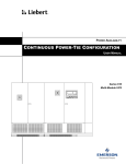
1
US00827451 1B2
(12) United States Patent
(10) Patent No.:
Sato
(54)
75
(
(45) Date of Patent:
APPARATUS FOR DISPLAYING WIRING
I
)
US 8,274,511 B2
t _
nven or.
Y Q h_ s t T
JP
a us 1 a o, okyo (
Sep. 25, 2012
FOREIGN PATENT DOCUMENTS
JP
2005-004726
* Cited by examiner
1/2005
(73) Assignee: Honda Motor Co., Ltd., Tokyo (JP)
( * )
Notice:
(21)
patent is extended or adjusted under 35
U_S_C_ 154(1)) by 681 days_
APPI' NO‘: 12/285,933
(22)
(65)
Subject to any disclaimer, the term of this
Filed:
Oct. 16, 2008
Prior Publication Data
Us 2009/0146997 A1
_
(57)
Jun 11, 2009
_
_
Prlmary Exammer *Damel Washbum
Assistant Examiner * Donna Ricks
(74) Attorney, Agent, or Firm * Squire Sanders (US) LLP
ABSTRACT
The present invention provides an apparatus Which displays a
plan Wiring diagram and three-dimensional layout diagram
(30)
Foreign Application Priority Data
Oct. 23, 2007
Oct. 23, 2007
(51)
(52)
(58)
IIlt- ClG06T 17/00
G06T 15/00
G06F 19/00
(JP) ............................... .. 2007-274754
(JP) ............................... .. 2007-274798
?rst storage for storing an image of a plan Wiring diagram
Which shoWs parts and Wirings and a second storage for
storing a three-dimensional layout of an apparatus Which
incorporates the parts and the Wirings, and a third storage for
storing intermediate images transitional betWeen a starting
image in the plan Wiring diagram and an ending image of a
shape of the corresponding Wiring in the three-dimensional
(2006.01)
(2006.01)
(2006.01)
US. Cl. ......................... .. 345/420; 345/619; 700/97
Field of Classi?cation Search ...................... .. None
See application ?le for complete Search history,
(56)
by associating them With each other so that they can be
vieWed easily. A apparatus for displaying Wiring includes a
layout. A processor displays the plan Wiring diagram on the
display device by retrieving the plan Wiring diagram from the
?rst storage based on a user’s selection, and retrieves the
intermediate images of a Wiring from the third storage When
References Cited
the Wiring is selected from the plan Wiring diagram and dis
U.S. PATENT DOCUMENTS
plays transitions to the shape shoWn in the three-dimensional
layout.
5,506,950 A *
4/1996 Hughes et a1. .............. .. 345/420
6,970,755 B2* 11/2005 Sakakura et a1.
2006/0214947 Al*
9/2006 Boose et a1. ............... .7345/619
E]
13 Claims, 7 Drawing Sheets
US. Patent
Sep. 25, 2012
Sheet 2 of7
US 8,274,511 B2
US. Patent
L
.
_
_
-
-
-
-
-
_
Sep. 25, 2012
_
-
-
-
I
in .......
L
.
_
-
-
-
-
_
_
_
-
Sheet 3 of7
-
-
-
A
_________
"
L
_
_
_
-
-
-
-
_
_
-
_
-
J
L
.
-
_
-
_
_
_
_
-
_
....................
J" ii
<
_
US 8,274,511 B2
:|
N
-
-
-
-|
US. Patent
Sep. 25, 2012
Sheet 4 of7
US 8,274,511 B2
US. Patent
Sep. 25, 2012
w
Sheet 5 of7
US 8,274,511 B2
US. Patent
Sep. 25, 2012
Sheet 6 of7
US 8,274,511 B2
HEADLIGT
PGM-FI
I
R0 1:
E
Q
<
US 8,274,5ll B2
1
2
APPARATUS FOR DISPLAYING WIRING
the plan Wiring diagram on the display device by retrieving
BACKGROUND OF THE INVENTION
the plan Wiring diagram from the ?rst storage based on user’ s
selection, and retrieves intermediate images of a Wiring from
the third storage When the Wiring is selected from the plan
1. Field of the Invention
The present invention relates to an apparatus for displaying
Wiring diagram and displays continuous transition until the
Wiring is illustrated by a shape in the three-dimensional lay
out diagram.
Wiring Which can graphically display correspondence
betWeen a plan Wiring diagram of an electric circuit and a
Since continuous transition of the Wiring the user selected
geographical layout diagram Which represents layout of Wir
from the plan Wiring diagram is displayed until the Wiring
ings in an actual machine or apparatus.
takes the three-dimensional shape in the three-dimensional
layout diagram, the present invention can make it easy for the
user to recogniZe correspondence betWeen the plan Wiring
2. Description of the Related Art
Instruction manuals such as automotive service manuals
contain a plan Wiring diagram shoWing an electrical system
and a three-dimensional layout diagram shoWing a geo
graphical layout of Wirings in illustrations of an automobile.
diagram and three-dimensional layout diagram.
According to one aspect of the present invention, the appa
ratus for displaying Wiring further comprises a forth storage
adapted to store positions and shapes of the parts in the plan
Both manuals are referred to during servicing of the automo
bile.
Wiring diagram in association With three-dimensional posi
Recently, plan Wiring diagrams and geographical layout
tions and three-dimensional shapes of the parts in the three
diagrams have become very complicated leading to a practice
of referring to a service manual on a display screen. The
service manual is converted into an electronic form. In a
20
Wiring diagram from the ?rst storage based on a user’ s selec
service manual in electronic form, a Wiring diagram and a
circuit board With electronic components mounted are dis
played together in a split display screen or a position in the
layout diagram corresponding to a position selected by a user
tion, and retrieves the three-dimensional position and three
dimensional shape of a part from the fourth storage When the
25
part is selected from the plan Wiring diagram for displaying
the part superimposed over the three-dimensional layout dia
in the plan Wiring diagram is displayed in a different color, for
example, as shoWn in Japanese Patent Application Publica
gram.
According to the present invention, since the three-dimen
tion No. 2005-4726.
sional shape of the part selected from the plan Wiring diagram
HoWever, plan Wiring diagrams represent electrical rela
tionships among components of an electrical system While
dimensional layout diagram. The processor displays the plan
Wiring diagram on the display device by retrieving the plan
30
by the user is retrieved and superimposed over the three
three-dimensional layout diagrams represent relationships
dimensional layout diagram. Thus, the user may recogniZe
betWeen positions and Wirings of parts. The tWo types of
diagram differ completely in the form of expression. It is
dif?cult to Watch the tWo diagrams alternately by shifting
one’s line of sight and understand the correspondence
correspondence between the plan Wiring diagram and three
dimensional layout diagram.
betWeen the tWo diagrams.
In automobiles, Wirings are often bundled into a Wiring
harness. Dif?culty is also encountered in ?nding out Where
the plurality of Wirings contained in the harness is located in
a plan Wiring diagram. Further, a single Wiring connector or a
According to an embodiment of the present invention, the
35
underlying draWing of the Wirings layers of the respective
40
single electrical component With multiple functions may be
split into multiple portions and is displayed at multiple loca
tions in a plan Wiring diagram. This makes it dif?cult to
recogniZe the Wiring connector or electrical component.
When similar parts are placed in a concentrated manner such
as When a plurality of electronic control units (ECU) are
plan Wiring diagram is formed superimposing on a general
45
Wirings. Intermediate images are provided for each layer.
According to another embodiment of the present invention,
the intermediate images are generated by morphing.
According to another embodiment of the present invention,
While displaying the intermediate images of the selected Wir
ing, the processor erases the general underlying draWing of
the Wirings and retrieves and gradually displays a general
underlying draWing of a corresponding three-dimensional
layout on the display.
According to another form of the present invention, an
apparatus for displaying Wiring comprises a ?rst storage
placed in layers, it is not easy to distinguish the parts.
adapted to store an image of a plan Wiring diagram Which
SUMMARY OF THE INVENTION
shoWs parts and Wirings, a second storage adapted to store a
50
An object of the present invention is to provide an appara
tus Which can display a plan Wiring diagram and three-dimen
sional layout diagram by associating them With each other so
that they can be vieWed easily.
To achieve the above object, the present invention provides
adapted to store intermediate images transitional betWeen a
starting image and an ending image. The three-dimensional
55
an apparatus for displaying Wiring. The apparatus comprises
dimensional layout diagram on the display device by retriev
ing the three-dimensional layout diagram from the second
diagram Which shoWs parts and Wirings, a second storage
adapted to store a three-dimensional layout diagram of an
Each of the Wirings shoWn in the plan Wiring diagram is a
starting image and the shape of a corresponding Wiring in the
three-dimensional layout diagram is an ending image.
The apparatus further comprises a processor adapted to
display images on a display device. The processor displays
layout diagram is the starting image and the plan Wiring
diagram is the ending image.
The apparatus includes a processor adapted to display
images on a display device. The processor displays the three
a ?rst storage adapted to store an image of a plan Wiring
apparatus Which incorporates the parts and the Wirings, and a
third storage adapted to store intermediate images Which are
transitional betWeen a starting image and an ending image.
three-dimensional layout diagram of an apparatus Which
incorporates the parts and the Wirings, and a third storage
60
storage based on a user’s selection, and retrieves the interme
diate images of a Wiring from the third storage When the
Wiring is selected from the three-dimensional layout diagram.
Continuous transition is displayed until the Wire Appears in
the plan Wiring diagram.
65
Since transition of the Wiring selected from the three-di
mensional layout diagram by the user is displayed until the
Wire Assumes the shape and position in the plan Wiring dia
US 8,274,511 B2
4
3
gram, the user may recognize correspondence between the
FIG. 5 is a diagram shoWing a relationship betWeen a plan
three-dimensional layout diagram and plan Wiring diagram.
Wiring diagram and three-dimensional layout diagram Where
According to an embodiment of the present invention, the
a single part is split into tWo portions in the plan Wiring
diagram.
apparatus for displaying Wiring further comprises a forth
storage adapted to store positions and shapes of the parts in
the plan Wiring diagram in association With three-dimen
sional positions and shapes of the parts in the three-dimen
sional layout diagram. The processor displays the three-di
mensional layout diagram on the display device by retrieving
the three-dimensional layout diagram from the second stor
FIG. 6 is a diagram shoWing an example of correspondence
betWeen a three-dimensional layout diagram and plan Wiring
diagram of a harness containing multiple Wires.
FIG. 7 is a diagram shoWing an example of transitions from
a three-dimensional layout diagram to a plan Wiring diagram
When the transitions involve rotation of the three-dimensional
diagram.
age based on a user’s selection. The processor retrieves the
position and shape of a part in the plan Wiring diagram from
DETAILED DESCRIPTION OF THE PREFERRED
EMBODIMENTS
the fourth storage When the part is selected from the three
dimensional layout diagram and displays the part at a corre
sponding position in the plan Wiring diagram.
According to this embodiment, since the part selected from
the three-dimensional layout diagram by the user is displayed
at the position and in the shape of the part in the plan Wiring
diagram, the user may recogniZe correspondence betWeen the
Embodiments of the present invention Will be described
With reference to the draWings. An apparatus for displaying
Wire According to the present invention is implemented When
a computer program created for the present invention is
20
three-dimensional layout diagram and plan Wiring diagram.
According to another embodiment of the present invention,
the three-dimensional layout diagram is formed of superim
position of a general underlying draWing of a three-dimen
sional layout and layers of individual Wirings. The interme
diate images are provided for each layer.
According to another embodiment of the present invention,
the plan Wiring diagram is formed of superimposition of a
general underlying draWing of the Wirings and layers of the
respective Wirings.
installed on a general purpose computer such as a personal
computer. In its basic con?guration, the computer includes a
processor (CPU), a random access memory (RAM) Which
provides a Working area for the processor and temporarily
stores programs and data, a non-volatile storage device such
25
as a disk drive Which stores computer programs and data, a
display device such as a CRT display and a liquid crystal
display for displaying computer output, and input devices
such as a keyboard and mouse.
FIG. 1 is a block diagram shoWing an overall con?guration
30
of the apparatus for displaying Wire According to the present
invention. A disk storage device 10 stores an electronic
According to another embodiment of the present invention,
the intermediate images represent transitions Which take
manual 11 for automobile servicing. The electronic manual
place before a plurality of Wires bundled into a harness shoWn
in the three-dimensional layout diagram are displayed as
the electronic manual, underlying-drawing data storage 11B
Wirings in the plan Wiring diagram.
According to another embodiment of the present invention,
When the plurality of Wires bundled into a harness correspond
to a plurality of draWings in the plan Wiring diagram, the
processor displays identi?cation information about the plu
rality of draWings. When one of the draWings is selected, the
processor displays intermediate images for the selected draW
ing on the display.
According to another embodiment of the present invention,
the intermediate images are generated by morphing.
11 includes data stored in a menu screen data storage 11A for
35
40
45
The processor 20 realiZes a function of displaying Wire
According to the present invention With the disk storage
device 10, display device 30, and input devices 40. When a
the three-dimensional layout diagram and gradually displays
50
BRIEF DESCRIPTION OF THE DRAWINGS
FIG. 1 is a block diagram shoWing an overall con?guration
of a apparatus for displaying Wire According to the present
invention.
FIG. 2 is a diagram shoWing hoW transitions Which take
place from a plan Wiring diagram to a three-dimensional
layout diagram.
55
device 30 (23). Since the electronic manual itself is publicly
knoWn, detailed description is omitted. When the user selects
a fuel injection system (PGM-FI), brake system (ABS), head
diagram (25) in accordance With the menus and using input
60
devices 40 such as the keyboard and mouse, a plan Wiring
diagram is retrieved and displayed on the display device 30
(27).
FIG. 2 is a diagram illustrating hoW display on the display
device 30 changes from a plan vieW to a three-dimensional
vieW. Block 41 shoWs an example of a plan vieW displayed on
layout diagram.
Wiring diagram.
user starts the computer of the apparatus and selects the
program for the electronic manual, the processor 20 activates
the program for the electronic manual (21). Consequently, a
menu of the electronic manual is displayed on the display
light system, or the like and selects a page of a plan Wiring
FIG. 3 is a stop-motion diagram shoWing a mechanism of
transitions from a plan Wiring diagram to a three-dimensional
FIG. 4 is a stop-motion diagram shoWing a mechanism of
transitions from a three-dimensional layout diagram to a plan
storage 11A. The manual further includes planar layer data
storage 11C for storing planar layers for each Wiring, inter
mediate image data storage 11D for storing intermediate
images Which represent transitions in Wiring shape from the
shape in the plan Wiring diagram to the shape in a three
dimensional layout diagram and conversely from the three
dimensional shape in the three-dimensional layout diagram to
the shape in the plan Wiring diagram. The manual also
includes data storage 11E for storing three-dimensional layer
for each Wire and data storage 11F for storing underlying
draWing of the three-dimensional layout diagram.
According to another embodiment of the present invention,
While displaying the intermediate images of the selected Wir
ing, the processor erases the general underlying draWing of
a general draWing of a plan Wiring diagram containing the
corresponding Wiring on the display.
for a plan Wiring diagram linked to the menu screen data
65
the display device 30. The plan vieW is formed by superim
posing layers of individual Wirings and parts retrieved from
the data storage 11C over a underlying layer containing all the
US 8,274,511 B2
6
5
Wirings, Which is retrieved from the data storage 11B in FIG.
1. For example, if the number of Wirings and parts is thirty,
present invention. In a plan Wiring diagram, a single connec
thirty-one layers consisting of thirty Wiring layers plus one
tor, unit, or pin is sometimes split into multiple portions for
underlying layer are superimposed and displayed as a plan
convenience. In FIG. 5, a single connector C is split into
connector C1 and connector C2 in the plan Wiring diagram
(A). Connectors C1 and C2, Which actually are connector C as
FIG. 5 shoWs an embodiment of one application of the
vieW on the display device 30.
If the user selects Wire A by placing a cursor on Wire A in
the plan vieW and clicking the mouse or entering a part num
ber of Wire A via an input device 40 (29), the layer of Wire A
illustrated in the three-dimensional layout diagram. In this
case, When the user selects connector C1 from the plan Wiring
diagram (A), both connectors C1 and C2 are highlighted and
is superimposed over the underlying draWing of all the Wir
ings. The WireA is highlighted by bold lines or by color. Next,
transitions from the plan Wiring diagram (A) to the three
dimensional layout diagram (B) are displayed on the display
device 30 using an animated display created by morphing
When the user pushes a con?rmation button (not shoWn) dis
played on a screen of the display device 30, for example, by
clicking the button With a mouse, Wire A changes its shape
gradually to a three-dimensional shape as shoWn in block 46
technique described With reference to FIG. 3. Connectors C1
and C2 are displayed in the three-dimensional layout diagram
through intermediate images 7 (FIG. 2). The three dimen
(B) as connector C Which is a single part.
sional shape is superimposed over an underlying draWing of
a three-dimensional layout retrieved from data storage 11F
According to a second aspect of the present invention,
transitions from a three-dimensional layout diagram to a plan
storing the three-dimensional underlying draWings.
Wiring diagram are displayed continuously. Returning to FIG.
The speed of transition may be adjusted using a scroll bar
49.
1, When the user starts the program of the electronic manual
20
FIG. 3 illustrates stop-motion transitions. First, a plan vieW
41 selected by the user is displayed on the display device 30,
Which comprises an underlying draWing retrieved from the
manual (23), an appropriate underlying draWing is retrieved
from the three-dimensional underlying-draWing data storage
11F. Three-dimensional layers of a plurality of appropriate
data storage 11B and superimposed layers of multiple Wirings
retrieved from data storage 11C. When the user selects WireA
from the Wiring diagram in the manner described above, a
layer 47 of Wire A is superimposed over an image 41 of the
25
storage 11E, and the three-dimensional layout diagram 46 is
underlying draWing and multiple three-dimensional layers
(27). When the user selects Wire A by placing the cursor on
30
dimensional layout diagram (33).
underlying draWing of the three-dimensional layout of the
automobile retrieved from the storage 11F (35). Then, mul
tiple layers of three-dimensional diagrams of the Wirings
Wire A in the three-dimensional layout diagram 46 and click
ing the mouse or by entering the part number of Wire A With
an input device 40, the layer of Wire A is superimposed over
the underlying draWing of the general three-dimensional lay
In the meantime, the underlying draWing of the three
dimensional layout diagram disappears gradually from a dis
play screen, resulting in a blank image 42 (31). At the same
time, an image 46 appears gradually on the display screen
With the layer 48 of Wire A being superimposed over the
Wirings are retrieved from the three-dimensional layer data
displayed on the display device 30 as a superimposition of the
plan Wiring diagram, Wire A being highlighted by bold lines
or by color. Next, the intermediate images of the layer 47 are
retrieved from the intermediate image data storage 11D to
represent transitions to a corresponding layer 48 in the three
(21) and selects, for example, the three-dimensional layout
diagram 46 shoWn in FIG. 2 from the menu of the electronic
35
40
contained in the underlying draWing are retrieved from the
data storage 11E and superimposed over the underlying draW
out diagram. Wire A is highlighted by bold lines or by color.
Next, When the user pushs the Con?rmation button dis
played on the screen of the display device 30, for example, by
clicking the button With a mouse, the underlying draWing of
the plan Wiring diagram including WireA is retrieved from the
planar underlying-draWing data storage 11B, the layers of
multiple Wirings contained in the underlying draWing are
ing draWing in such a Way as to take an appropriate position
retrieved from the planar layer data storage 11C, and a stack
of the underlying draWing and the layers appears gradually on
the display device 30 as the image 41 of the plan Wiring
diagram. Then, the intermediate images 7 of Wire A in the
three-dimensional layout diagram 46 are retrieved from the
intermediate image data storage 11D to display transitions
continuously until Wire A takes the shape shoWn in the plan
on the underlying draWing.
The intermediate images used here are generated using a
Wiring diagram. Eventually, the layer of Wire A is superim
posed over the underlying draWing of the plan Wiring diagram
ing to complete the image 46 of the three-dimensional layout
diagram in Which Wire A is highlighted (35).
The layer of each Wiring is linked to the underlying draW
ing using a part number and superimposed over the underly
morphing technique. The morphing technique generates
45
50
to complete the image 41.
moving-image data Which represents smooth transitions from
Consequently, the image 41 of the plan Wiring diagram is
a still image to another still image and is used in the ?eld of
55
displayed on the display device 30 With Wire A highlighted. In
parallel With this operation, the image 46 of the three-dimen
sional layout diagram fades out as it is thinned gradually.
The speed of transition from image 46 to image 41 can be
adjusted using the scroll bar 49 displayed on the screen of the
display device 30.
FIG. 4 illustrates stop-motion vieW of such transition. The
animation. Morphing softWare products are commercially
available. The morphing technique handles images in GIF,
J PEG, TIFF, PNG, and other ?le formats.
In one example, Wire A and part B connected to Wire A are
selected. When Wire A and part B are selected, a layer 43 of
part B (e.g., an electronic control unit ECU) and layer 47 of
transition How is opposite in direction to the one shoWn in
Wire A are highlighted. Transition of part B into a three
dimensional layer 44 is represented by intermediate images,
Which are produced by the morphing technique. The three
60
selected from the menu by the user is displayed on the display
device 30. The three-dimensional layout diagram 46 includes
the underlying draWing retrieved from the three-dimensional
dimensional layer 44 of part B is superimposed over the
underlying draWing of the three-dimensional layout diagram
of the automobile to resulting in the three-dimensional layout
diagram 46. In this Way, WireA and part B connected to Wire
A are superimposed over the underlying draWing of the three
dimensional layout diagram.
FIG. 3. First, the three-dimensional layout diagram 46
underlying-draWing data storage 11F. Multiple layers illus
65
trating the Wirings and parts included in the structure of the
underlying draWing are retrieved from the planar layer data
storage 11C and superimposed.
US 8,274,511 B2
8
7
shape via intermediate images 7. The three dimensional vieW
is shoWn in block 46. The layer of part B is superimposed over
an underlying layer of three-dimensional vieW retrieved from
the three-dimensional underlying-draWing data storage 11F.
The speed of transition can be adjusted by sliding the
When the user selects Wire A from the three-dimensional
layout diagram in the manner described above, the layer 48 of
Wire A is highlighted by bold lines or by color. Next, the
intermediate images of the layer 48 are retrieved from the
intermediate image data storage 11D to continuously display
transition to a corresponding layer 47 in the three-dimen
button of the scroll bar 49.
FIG. 3 shoWs stop-motion transition. First, a plan Wiring
diagram 41 selected by the user is displayed on the display
sional layout diagram (33). Consequently, the shape of WireA
in the layer 48 changes gradually to the shape of WireA in the
device 30. Layers of multiple Wirings retrieved from the pla
layer 47 of the plan Wiring diagram. Meanwhile, the layers in
the underlying draWing of the three-dimensional layout dia
gram disappear gradually from the display screen, resulting in
a blank image 45 (31). An underlying draWing of the plan
Wiring diagram including Wire A is retrieved from the planar
nar layer data storage 11C are superimposed over an under
lying draWing retrieved from the planar underlying-draWing
data storage 11B. When the user selects part B from the
Wiring diagram in the manner described above, the layer 43 of
part B is displayed over an image 41 of the plan Wiring
diagram. Part B is highlighted by bold lines or by color. Next,
the intermediate images of the layer 43 are retrieved from the
underlying-draWing data storage 11B and appears gradually
on the display screen (35). At the same time, the layers of the
other Wirings and parts contained in the underlying draWing
intermediate image data storage 11D and transition to a cor
are retrieved from the planar layer data storage 11C and
responding layer 44 in the three-dimensional diagram is dis
eventually superimposed over the underlying draWing. FIG. 4
illustrates a case in Which Wire A and part B that is connected
to Wire A are selected, as in the case of FIG. 3.
Referring noW to FIG. 6, the user selects a three-dimen
played (33).
20
42 (31). At the same time, an image 46 appears gradually on
sional layout vieW such as shoWn in FIG. 6(A), out of the
electronic manual (25) for display on the display device 30.
When the user places the cursor on a harness E, a bundle of 25
multiple Wires contained in the harness has its transition to a
30
Wiring diagrams of Wires 1, 2, and 3 are displayed on the
display device.
In one example, When harness E is selected in FIG. 6(A),
types of Wires contained in the harness are presented in text
form on the display to specify to Which system the sires
belong, for example, a fuel injection system, a headlight
system, etc. Regarding the type of Wiring selected by the user,
transition to the plan Wiring diagram are displayed. The other
types of Wiring, unless selected, do not have their transition to
mensional vieW of the Wirings contained in the underlying
draWing are retrieved from the three-dimensional layer data
storage 11E and are superimposed over the underlying layer
resulting in the image 46 of the three-dimensional vieW in
Which part B is highlighted (35).
The layer of each part or Wiring is linked to the underlying
layer using a part number and is superimposed over the under
lying layer to align With the underlying layer.
35
The intermediate images used here are generated using a
morphing technique. The morphing technique generates
moving-image data Which represents smooth transition from
a still image to another still image and is used in the ?eld of
40
the plan Wiring diagram displayed. Thus, a functional part
Which needs to be checked may be displayed on a single
screen in an easy-to-vieW fashion, reducing the amount of
data for intermediate images greatly. In this case, a combina
tion of part numbers at each Wiring connection in the plan
Wiring diagram is associated With the harness.
the display screen With the layer 44 of part B superimposed
over the underlying layer of the three-dimensional vieW of the
automobile retrieved from the three-dimensional underlying
draWing data storage 11F (35). Multiple layers of three-di
Wires, in the draWing and clicks the mouse (29), the processor
20 displays transition from the harness to the plan Wiring
diagram using intermediate images. In this case, each of
plan Wiring diagram. In the example of FIG. 6(B), the plan
In parallel, the underlying layer of the plan vieW disappears
gradually from the display screen, resulting in a blank image
animation. Morphing softWare products are commercially
available. The morphing technique handles images in GIF,
J PEG, TIFF, PNG, and other ?le formats.
In one example, part B and Wire A connected to part B are
selected. When part B and Wire A are selected, the layer 47 of
WireA connected to part B as Well as the layer 43 of part B are
45
highlighted. Intermediate images are produced by the mor
phing technique to shoW the manner Wire A changes to a
shape in a three-dimensional layer 48. The three-dimensional
FIG. 7 shoWs a variation of the second aspect of the present
invention. When the user places the cursor on Wire F in the
layer 48 of Wire A is superimposed over the underlying layer
three-dimensional vieW as shoWn in FIG. 7(A) and clicks the
mouse, the processor 20 rotates the three-dimensional vieW
of the three-dimensional vieW of the automobile to form the
three-dimensional vieW 46. In this Way, part B and WireA that
is connected to part B are displayed together in the three
dimensional vieW.
50
from (A) to (B), and then from (B) to (C). In FIG. 7(C) Wire
F appears in the front of the vieW. The processor 20 displays
transition to a plan Wiring diagram (D) Which contains Wire F
beginning With the image in FIG. 7(C) and using intermediate
images. As a plan Wiring diagram is associated With the
According to one aspect of the present invention, transition
from a part selected from a three-dimensional layout to a
55
shape in a plan Wiring diagram is sequentially displayed.
three-dimensional vieW, the amount of data needed to create
Returning to FIG. 1, When the user starts the program of the
the intermediate images may be greatly reduced.
Next, another embodiment of the present invention Will be
electronic manual (21) and selects, for example, the three
described. Referring to FIG. 2, When the user selects part B in
electronic manual (23), an appropriate underlying draWing is
retrieved from the three-dimensional underlying-draWing
the plan Wiring diagram by placing the cursor on part B and
dimensional layout 46 shoWn in FIG. 2 from the menu of the
60
data storage 11F. Three-dimensional layers of a plurality of
appropriate parts and Wirings are retrieved from the three
dimensional layer data storage 11E, and superimposed over
clicking the mouse or by entering a part number of part B via
the input device 40 (29), only the layer of part B is superim
posed over the underlying layers of all the Wirings and is
the underlying layer to form the three-dimensional layout 46,
highlighted by bold lines or by color. When the user pushed
the con?rmation button displayed on the screen of the display
device 30, for example, by clicking the button With a mouse,
part B changes its shape gradually to a three-dimensional
65
Which is displayed on the display device 30 (27). When the
user selects part B by placing the cursor on part B in the
three-dimensional layout diagram 46 and clicking the mouse
US 8,274,511 B2
10
or by entering the part number of part B via an input device 40,
the layer of part B is superimposed over the underlying draW
What is claimed is:
1. An apparatus for displaying a plan Wiring diagram of
ing of the entire plan Wiring diagram. Part B is highlighted by
parts and Wirings in association With a three-dimensional
layout of a device incorporating the parts and Wirings, the
bold lines or by color.
Next, When the user pushes the Con?rmation button (not
shoWn) displayed on the screen of the display device 30, for
example, by clicking the button With a mouse, the underlying
5
apparatus comprising:
a ?rst storage for storing an underlying draWing of the plan
Wiring diagram Which illustrates parts and Wirings;
draWing of the plan Wiring diagram including part B is
retrieved from the planar underlying-drawing data storage
a second storage for storing an underlying draWing of the
three-dimensional layout of a device Which incorporates
11B. The layers of multiple parts and Wirings contained in the
underlying draWing are retrieved from the planar layer data
storage 11C and superimposed over the underlying draWing
the parts and the Wirings;
a third storage for storing intermediate images of the
layer. The layers appear gradually on the display device 30 as
diagram With a starting image of each piece of Wiring
being a shape corresponding to the Wiring in the plan
Wiring diagram and With an ending image of each piece
of Wiring being a shape corresponding to the Wiring in
the three-dimensional layout, said intermediate images
shoWing transition of the shape of a corresponding piece
of the Wiring; and
shapes of respective pieces of Wirings in the plan Wiring
the image 41 of the plan Wiring diagram. The intermediate
images 7 of part B layer in the three-dimensional layout
diagram 46 are retrieved from the intermediate image data
storage 11D to display transition of part B. Eventually, the
layer of part B is superimposed over the underlying draWing
of the plan Wiring diagram to complete the image 41.
Consequently, the image 41 of the plan Wiring diagram is
displayed on the display device 30 With part B highlighted.
The image 46 of the three-dimensional layout fades out by
20
a processor adapted to display images on a display screen,
thinning.
The speed of transition from the image 46 to the image 41
can be adjusted by sliding the button of the scroll bar 49
25
a user’s selection,
responsive to selection of a piece of Wiring by a user from
displayed on the screen of the display device 30.
the displayed plan Wiring diagram, sequentially retrieve
FIG. 4 shoWs display stop-motion transition. The transition
How is opposite in direction to the one shoWn in FIG. 3. First,
the three-dimensional layout 46 selected from the menu by
the user is displayed on the display device 30. The three
30
dimensional layout 46 includes the underlying draWing
retrieved from the three-dimensional underlying-draWing
2. The apparatus for displaying Wire according to claim 1,
contained in the underlying draWing are retrieved from the
further comprising
layer storage 11C and superimposed over the underlying
draWing.
When the user selects part B from the three-dimensional
40
a fourth storage for storing positions and shapes of the parts
in the plan Wiring diagram in association With three
dimensional positions and shapes of the parts in the
three-dimensional layout, Wherein the processor dis
plays the plan Wiring diagram on the display device by
retrieving the plan Wiring diagram from the ?rst storage
image data storage 11D to display transition to the corre
sponding layer 43 in the plan Wiring layout (33). The shape of
part B in the layer 44 changes gradually to the shape of part B
in the layer 43 of the plan Wiring vieW. MeanWhile, the layer
in the underlying draWing of the three-dimensional layout
disappears gradually from the display screen, resulting in a
blank image 45 (31). The underlying draWing of the plan vieW
including part B is retrieved from the planar underlying
intermediate images of the shape corresponding to the
selected piece of Wiring from the third storage to display
transition of the shape of the piece of Wiring until the
shape transforms into the shape that may be superim
posed to a layer of the underlying draWing of the three
dimensional layout.
data storage 11F. Multiple layers of the parts and Wirings
layout in the manner described above, the layer 44 of part B is
highlighted by bold lines or by color. The intermediate
images of the layer 44 are retrieved from the intermediate
the processor being con?gured to:
display the plan Wiring diagram in the form of said under
lying draWing on the display screen by retrieving the
plan Wiring diagram from the ?rst storage responsive to
based on a user’s selection, and retrieves the three-di
45
mensional position and shape of the part from the fourth
storage When the part is selected from the plan Wiring
diagram and superimposes the part over the three-di
mensional layout.
3. The apparatus for displaying Wire according to claim 1,
Incidentally, FIG. 4 shoWs a case in Which part B and Wire
A that is connected to part B are selected, as in the case of FIG.
Wherein the plan Wiring diagram is formed of superimposi
tion of a general underlying layer of the Wirings and layers of
respective Wirings, and the intermediate images are provided
for each layer.
4. The apparatus for displaying Wire according to claim 3,
Wherein the intermediate images are generated by morphing.
5. The apparatus for displaying Wiring according to claim
4, Wherein While the intermediate images of the selected
3. In the example of FIG. 5, connector C is split into connector
Wiring are displayed, the processor erases the general under
50
draWing data storage 11B and appears gradually on the dis
play screen (35). At the same time, the layers of the other
Wirings and parts contained in the underlying draWing are
retrieved from the planar layer data storage 11C and super
imposed over the underlying draWing.
55
C1 and connector C2 in the plan Wiring diagram (A). Con
nector C is displayed as a single part in the three-dimensional
60
layout diagram (B). Conversely, connector C may be selected
in the three-dimensional layout diagram (B) and displayed in
the plan Wiring diagram (A) as split into connectors C1 and
on the display device.
6.A apparatus for displaying a plan Wiring diagram of parts
and Wirings in association With three-dimensional layout of a
device incorporating the parts and the Wirings, the apparatus
C2.
The present invention has been described above by citing
concrete examples, but it should be noted that the present
invention is not limited to these concrete examples.
lying layer of the Wirings and retrieves a general underlying
layer of a corresponding three-dimensional layout for display
65
comprising:
a ?rst storage for storing an underlying draWing of the plan
Wiring diagram Which illustrates parts and Wirings;
US 8,274,511 B2
11
12
diagram from the fourth storage responsive to selection
of the part from the three-dimensional layout, and dis
plays the part at a corresponding position in the plan
a second storage for storing an underlying drawing of the
three-dimensional layout of a device Which incorporates
the parts and the Wirings;
a third storage for storing intermediate images of the
shapes of respective pieces of Wirings in the three-di
mensional layout With a starting image of each piece of
Wiring being a shape corresponding to the Wiring in the
Wiring diagram.
5
Wherein the three-dimensional layout is formed of a super
imposition of a general underlying layer of a three-dimen
sional layout and layers of individual Wirings.
9. The apparatus for displaying Wire according to claim 6,
Wherein the plan Wiring diagram is formed of a superimpo
sition of a general underlying layer of the Wirings and layers
of the respective Wirings.
10. The apparatus for displaying Wire according to claim 6,
three-dimensional layout and With an ending image of
each piece of Wiring being a shape corresponding to the
Wiring in the plan Wiring diagram, said intermediate
images shoWing transition of the shape of a correspond
ing piece of the Wiring; and
a processor adapted to display images on a display screen,
Wherein While the intermediate images of the selected Wiring
are displayed, the processor erases the general underlying
draWing of the three-dimensional layout and gradually dis
plays a underlying draWing of a plan Wiring diagram contain
Wherein the processor being con?gured to:
display the three-dimensional layout on the display screen
in the form of said underlying draWing by retrieving the
three-dimensional layout from the second storage
ing the corresponding Wiring.
responsive to a user’s selection,
responsive to selection of a piece of Wiring by a user from
the displayed three-dimensional layout, sequentially
20
retrieve the intermediate images of the piece of Wiring
from the third storage, and display transition of the shape
of the piece of Wiring until the shape transforms into the
25
7. The apparatus for displaying Wiring according to claim
6, further comprising
a fourth storage for storing positions and shapes of the parts
in the plan Wiring diagram in association With three
dimensional positions and shapes of the parts in the
three-dimensional layout diagram, Wherein the proces
sor displays the three-dimensional layout on the display
device by retrieving the three-dimensional layout from
the second storage based on a user’s selection, retrieves
the position and shape of the part in the plan Wiring
11. The apparatus for displaying Wire according to claim
10, Wherein the intermediate images represent transition of a
plurality of Wirings bundled in a harness in the three-dimen
sional layout to Wirings in the plan Wiring diagram.
12. The apparatus for displaying Wiring according to claim
shape that may be superimposed to a layer of the under
lying draWing of the plan Wiring diagram.
8. The apparatus for displaying Wire according to claim 6,
11, Wherein When the plurality of Wirings bundled into a
harness corresponds to a plurality of draWings in the plan
Wiring diagram, the processor displays identi?cation infor
mation about the plurality of draWings on the display device,
and When one of the draWings is selected, the processor dis
plays intermediate images to the selected draWing on the
30
display device.
13. The apparatus for displaying Wire According to claim
12, Wherein the intermediate images are produced by mor
phing.