1
US008327283B2
(12) Ulllted States Patent
(10) Patent N0.:
Shinohara et al.
(54)
US 8,327,283 B2
(45) Date of Patent:
ELECTRONIC APPARATUS WITH DISPLAY
5,706,457 A *
5,923,737 A *
UNIT TO DISPLAY ICON FOR MODE AND
ASSOCIATED INFORMATION-PROCESSING
5,977,976 A
METHOD
6,091,450 A
Dec. 4, 2012
1/1998 DWyer et a1. ............... .. 715/835
7/1999 Welshut 6t 31
11/1999 Maeda ~~~~~~~~~~~~~~~~~~~~~~~~ ~~ 715/841
7/2000 Hlrasawa
(Continued)
(75) Inventors: Michinari Shinohara, KanagaWa (JP);
Hiroshi MorikaWa, KanagaWa (JP)
_
FOREIGN PATENT DOCUMENTS
EP
1 246 434 A1
(73) Ass1gnee: Ricoh Company, Limited, Tokyo (JP)
(*)
Notice:
Subject to any disclaimer, the term of this
patent is extended or adjusted under 35
U.S.C. 154(b) by 1140 days.
OTHER PUBLICATIONS
_
_
_
_
N°~ 2005-0355267
Oct. 31, 2007
(65)
_
Japanese Of?ce Act10n lssued Jul. 31, 2007, 1n Patent Appllcatlon
(21) Appl. N0.: 11/933,059
(22) Filed:
10/2002
(Continued)
(Commued)
Pnor Pubhcatlon Data
Us Zoos/0072172 A1
Primary Examiner * Doug Hutton, Jr.
Mar‘ 20’ 2008
Assistant Examiner * Soumya Dasgupta
Related US. Application Data
(74) A110""6)’,
(63)
Continuation of application No. 11/082,781, ?led on
Mar. 18, 2005, noW Pat. No. 7,493,571.
(30)
Foreign Application Priority Data
Agent)
0"
Firm * Oblon:
Spivak:
McClelland, Maier & Neustadt, L.L.P.
57
ABSTRACT
( )
An image data taking unit takes image data of an object and
Mar. 19, 2004
Feb. 15, 2005
(JP) ............................... .. 2004-080795
(JP) ............................... .. 2005-038267
Stores the image data therein as an image data ?1e_A display
unit displays the image data Stored in the image data taking
unit. A mode-switching unit sWitches betWeen a close-up
(2006 01)
715/772 715j838_ 715/815 715/810
mode and a distant-View mode of the image data taking unit.
The close-up mode is for the object With a close distance and
(51)
Int Cl
(52)
G081? /048
U 5 Cl
(58)
Field of Classi?cation Search
' '
(56)
' """ "
’
’
’ 71 5/812’
the distant-View mode is for the object With a long distance. A
71 5/772
810 812’
See application ?le for Complete gearcil hist’ory ’
'
References Cited
display control unit, When the close-up mode is on, displays a
close-up mode icon on the display unit, and When the distant
VieW mode is on, displays a distant-mode icon on the display
unit. The display control unit, When the mode-switching unit
sWitches the distant-View mode on, re P laces the close-u P icon
displayed on a predetermined position on the display unit by
the distant-mode icon on the predetermined position.
US. PATENT DOCUMENTS
5,182,641 A *
1/1993
Diner et al. ................... .. 348/86
5,564,004 A
10/1996 Grossman et 31.
5,565,888 A
10/1996 Selker
9 Claims, 14 Drawing Sheets
a4
US 8,327,283 B2
Page 2
U.S. PATENT DOCUMENTS
2003-101824
4/2003
8,888,888 8
88888 88888888.
5;
533333333
3333;
6,169,854 B1 *
1/2001
JP
2003633380
11/2003
JP
2004_21554
1/2004
JP
200461762
20004
6,215,482 B1
6,327,001 B1 *
Hasegawa et al. ............ .. 396/56
4/2001 Hwang
12/2001
Yamagishi .................. .. 348/552
6,417,869 B1*
7/2002
. 715/718
JP
2006-47602
2/2006
6,453,078 B2 *
9/2002 Bub1e et al. ................. .. 382/305
JP
2006_86758
300%
6,600,499 B1
7,036,080 B1
7/2003 MacPhail
4/2006 James et al.
7,149,781 B2
Do ......... ..
.
OTHER PUBLICATIONS
12/2006 Aoyama
7,155,336 B2 *
12/2006 Dorfman et a1~ ~~~~~~~~~~~~ ~~ 701/200
Japanese Of?ceActionissued Dec. 4, 2007, in PatentApplication No.
7,155,676 B2
12/2006 Land et al.
2005038267
7,280,238
10/2007
B2
7,403,705 B2
7,600,192 B1 *
Akiyoshi
10/2009
2003/0164855 A1*
9/2003
2004/0119851 A1
6/2004 Kaku
2004/0264952 A1
A1
2007/0285702 A1
OnoZaWa
.
.
.
.
.
110-2007454435‘
Japanese Decision ofRejection issuedApr. 15, 2008, in PatentAppli
cation No. 2007-254435.
Japanese Of?ce Action issued Aug. 3, 2010, in Patent Application
.
12/2007 Ak1yosh1
FOREIGN PATENT DOCUMENTS
1 315 369 Al
. 345/767
Grant et al. ................. .. 345/763
12/2004 Oeda et al.
2/2006
.
Japanese Of?ce Act1on 1ssued Nov. 20, 2007, 1n Patent Appl1cat1on
Hashimoto et 31. ......... .. 715/802
1/2003 Baar et a1. .... ..
2006/0029381
'
7/2008 OnOZaWa
2003/0007006 A1 *
EP
JP
5/2003
No‘ 2008456842
- Japanese Dec1s1on
of Rejectlon
1ssued
Nov. 24, 2010, 1n
PatentAppl1-
cation No‘ 2008456842
FiXya Technical Suppor-t;-“Online User Manual and Guide for Sony
Cyber-Shot DSCP92 D1g1tal Camera”; Copyrlght Date 2003; http://
WWW.?Xya.com/support/p325603-sonyicyberishotidscip92i
JP
11-119316
4/1999
JP
11-146234
5/1999
JP
1l_275394
“V1999
dlgltalicamera/manual- 1 5724.
D1g1tal Camera F1neP1X S5000, Internet C1tat1on, Jul. 2003,
.
“
.
.
.
.
.
,,
.
.
JP
2000347974
120000
XP002383324, Retrleved from the Internet: URL:hhtp://WWW.
JP
JP
JP
2001_67163
2001-211354
2002-209138
3/2001
8/2001
7/2002
fu]1?lmusa.com/shared/b1n/S5000Manual.pdf (Retrleved on May
31, 2006), pp. 1-56.
Of?ce Action, issued Sep. 13, 2012, in European Application No. 05
JP
2002-223403
8/2002
005 866.8, pp. 1-6.
JP
2002-290784
10/2002
JP
2003-44207
2/2003
_
_
* clted by examlner
US. Patent
Dec. 4, 2012
Sheet 2 0f 14
US 8,327,283 B2
FIG. 2
3' 52 20a 33
@ d5
3F
E32
1600x1200
NORMAL DISPLAY IN WHICH
ICONS ARE OUT OF THE WAY
@
31L'
i}
'
5”’
E12
1600x1200
ICONS ARE DISPLAYED IN
LARGE SIZE IMMEDIATELY
BEFORE PHOTOGRAPHING
US. Patent
Dec. 4, 2012
Sheet 3 0f 14
US 8,327,283 B2
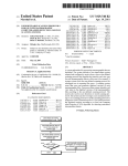
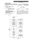
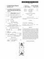
$101
ARE PHOTOGRAPHING
CONDITIONS READY ?
YES
,
NO
$102
NO
Is THERE CHANGE OF
SETTING BY USER OPERATION ?
YESl
$103
,1
sTART ENLARGED DISPLAY OF
TARGET ICONS (TIMER Is ON )
>
'
$104
Is THERE CONFIRMATION
OPERATION BY USER '2
NO
YES
CD 105
‘
NO
HAS PREDETERMINED
TIME PASSED '2
YEslY4
END ENLARGED DISPLAY OF
TARGET ICONS ( TIMER IS OFF )
Isms
US. Patent
Dec. 4, 2012
Sheet 4 0f 14
US 8,327,283 B2
FIG. 4
35a
35b
H
@
@
@1
1600x1200
IMMEDIATELY AFTER
PH OTOGRAPHABLE
MODE IS OBTAINED
rJ
@
Q
Q1
1600X1200
LARGE SETTING
INFORMATION DISAPPEARS
US. Patent
Dec. 4, 2012
Sheet 5 0f 14
US 8,327,283 B2
FIG. 5
@AUTO -:{=1- MF [E [63
10
41M
9999
@12s0f43
18
vH
US. Patent
Dec. 4, 2012
Sheet 6 0f 14
US 8,327,283 B2
61
62
32L
/J
1
SETTING SCREEN
@
ENLAR'GED DISPLAY 0F‘%/ ////
,ICONSTOBE
CHANGED%//9N
MACRO
PHOTOGRAPHING MODE
AF/MF/SNAP/DISTANT VIEW
WHITE BALANCE
ON
ON
ON
OFF
EXPOSURE CORRECTION
OFF
@
3.3‘- r’
[Q
Q]
.
'
34
31 L-
1600 x 1200
FIG. 7
70
71
72
73
US. Patent
Dec. 4, 2012
Sheet 7 0f 14
FIG. 8A
E
a
iBE'BXIE'BB
US 8,327,283 B2
US. Patent
Dec. 4, 2012
Sheet 8 0f 14
FIG. 8B
US 8,327,283 B2
US. Patent
Dec. 4,2012
US 8,327,283 B2
Sheet9 0f 14
FIG. 9A
35
IBEIDXIEBB
a
iBDEIXIE‘DEI
US. Patent
Dec. 4, 2012
Sheet 10 0f 14
FIG. 9B
US 8,327,283 B2
US. Patent
Dec. 4, 2012
Sheet 11 0114
US 8,327,283 B2
FIG. 9C
3nd E f w
99a
A
US. Patent
Dec. 4, 2012
Sheet 12 0f 14
FIG. 10A
@
{53BX13
US 8,327,283 B2
US. Patent
Dec. 4, 2012
Sheet 13 0f 14
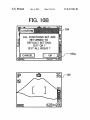
FIG. 108
ALL FUNCTIONS SET ARE
RETURNED TO
DEFAULT SETTING.
IS IT OK ?
IS IT ALL RIGHT ?
KCANCELJ?
US 8,327,283 B2
US. Patent
Dec. 4, 2012
Sheet 14 0f 14
FIG. 11
f- DEFAULT CURRENT SETTING‘
111a"
FLASH
écompuLsoRY
PROHIBITION FLASH
ISO AUTO
ISO 400
AF AUTOMATIC MF MANUAL
FOCUSING
FOCUSING
NORMAL
@ MACRO
PHOTOGRAPHING
112b
US 8,327,283 B2
US 8,327,283 B2
1
2
ELECTRONIC APPARATUS WITH DISPLAY
UNIT TO DISPLAY ICON FOR MODE AND
ASSOCIATED INFORMATION-PROCESSING
METHOD
may hinder the display of base image data. Further, all the
icons cannot be displayed because of the large siZe.
SUMMARY OF THE INVENTION
It is an object of the present invention to solve at least the
CROSS-REFERENCE TO RELATED
APPLICATIONS
above problems in the conventional technology.
An electronic apparatus, according to one aspect of the
This application is a continuation of and claims the bene?t
present invention, includes an image data taking unit that is
ofpriority under 35 U.S.C. §120 from US. Ser. No. 11/082,
781, ?led Mar. 18, 2005, now US. Pat. No. 7,493,571, and
claims the bene?t of priority under 35 U.S.C. §119 from
con?gured to take an image data of an object and store the
image data therein as an image data ?le; a display unit that is
con?gured to display the image data stored in the image data
taking unit; a mode- sWitching unit that is con?gured to sWitch
Japanese Patent Application Number 2004-080795, ?led
Mar. 19, 2004 and 2005-038267, ?led Feb. 15, 2005, the
betWeen a close-up mode and a distant-vieW mode of the
image data taking unit, Wherein the close-up mode is for the
entire contents of each Which are incorporated herein by
reference.
BACKGROUND OF THE INVENTION
20
1) Field of the Invention
vieW mode is on, display a distant-mode icon on the display
unit, Wherein the display control unit, When the mode-sWitch
ing unit sWitches the distant-vieW mode on, replaces the
The present invention relates to an electronic apparatus
With a display unit, an information-processing method, and a
computer product.
2) Description of the Related Art
25
In another aspect, the display control unit, When the mode
sWitching unit sWitches the distant-vieW mode on from the
use as a media of image information. These apparatuses can
close-up mode, displays the distant-vieW mode icon ?rst in an
provide various functions by handling the image information
30
tion on a main image on a display screen. Based on these icons
another predetermined position on the display unit.
In another aspect, the display control unit gradually
35
and the like that indicate a set operation mode of the device
and give guidance to a device user, the user can interact With
the device.
For example, Japanese Patent Application Laid-Open No.
40
H11-146234 discloses a conventional example of a device
having the OSD function. The invention described in this
publication relates to a digital camera. The digital camera has
a mode of reproducing and displaying image data stored in a
memory card, and a mode of displaying a photographed
image through the digital camera. Image data and character
data shoWing a counter, a date, a photographing condition,
and the like are combined, and the combined data are dis
played on a screen of a liquid crystal display device (LCD) as
a display unit. The invention disclosed in this publication has
50
unit displays the distant-vieW mode icon With the enlarged
siZe in a center portion of the display unit, and the distant
vieW mode icon With the reduced siZe in a peripheral portion
of the display unit.
In another aspect, the image data taking unit, even While
the display control unit displays the distant-vieW icon With the
enlarged siZe on the display unit, can take the image data.
A method, according to another aspect of the present inven
tion, of controlling an electronic apparatus provided With an
image data taking unit that is con?gured to take an image data
?le, and a display unit that is con?gured to display the image
data stored in the image data taking unit, includes sWitching
betWeen a close-up mode and a distant-vieW mode of the
an object of securing a normal display by avoiding a differ
image data taking unit, Wherein the close-up mode is for the
object With a closed distance and the distant-vieW mode is for
attributable to different scan speeds betWeen the display
modes.
55
the object With a long distance; and displaying, a close-up
mode icon on the display unit, When the close-up mode is on,
and a distant-mode icon on the display unit, When the distant
relatively small displays have the OSD function Which is used
vieW mode is on, Wherein the displaying includes, When the
close-up mode is sWitched to the distant-vieW mode at the
sWitching, replacing the close-up icon displayed on a prede
termined position on the display unit by the distant-mode icon
on the predetermined position.
In another aspect, the displaying includes, When the close
as the user interface. Further, in recent years, these devices
have various functions based on the progress of advanced
multiple functions. In this situation, many icons are displayed
on the screen of a limited siZe; therefore individual icons need
to be small.
When the icons are small, characters that are set on the
up mode is sWitched to the distant-vieW mode at the sWitch
screen have poor visibility because of garbled display. The
user cannot con?rm the oWn setting, and may make an erro
decreases the siZe of the distant-vieW mode icon from the
enlarged siZe to the reduced siZe.
In another aspect, the electronic apparatus includes one of
a digital camera and a portable phone, and the display control
of an object and store the image data therein as an image data
ence of siZes betWeen character data displayed on the screen
Digital cameras, portable telephones, and the like having
enlarged siZe on the predetermined position and subsequently
displays the distant-vieW mode icon in a reduced siZe on
An on-screen display (OSD) function is one of those func
tions, so far used as a user interface. According to the OSD
function, icons that indicate device states and operating con
ditions, characters, or the like are displayed in superimposi
close-up icon displayed on a predetermined position on the
display unit by the distant-mode icon on the predetermined
position.
Recently, digital still cameras, portable telephones
equipped With a digital camera, and the like are in Widespread
as electronic data.
object With a closed distance and the distant-vieW mode is for
the object With a long distance; and a display control unit that
is con?gured to, When the close-up mode is on, display a
close-up mode icon on the display unit, and When the distant
ing, displaying the distant-vieW mode icon ?rst in an enlarged
65
siZe on the predetermined position, and subsequently display
neous setting of functions. When display siZes of the charac
ing the distant-vieW mode icon in a reduced siZe on another
ters are increased to avoid the poor visibility, these characters
predetermined position on the display unit.
US 8,327,283 B2
3
4
In another aspect, the displaying includes, When subse
quently making the distant-vieW mode icon siZe reduced,
gradually making the distant-vieW mode icon siZe reduced.
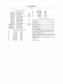
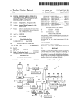
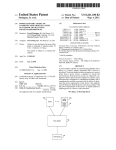
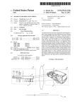
2 including an automatic focusing mechanism, a charge
coupled device (CCD) 3, a correlation double sampling
(CDS) circuit 4, an analog/digital A/D) converter 5, a digital
signal processing circuit 6, a compressing/expanding circuit
In another aspect, the electronic apparatus includes one of
a digital camera and a portable phone, and the displaying
includes displaying the distant-vieW mode icon With the
enlarged siZe in a center portion of the display unit, and the
distant-vieW mode icon With the reduced siZe in a peripheral
7, a dynamic random access memory (DRAM) 8, a memory
card 9, an LCD 10, a driver 11, a synchronous generator (SG)
invention are speci?cally set forth in or Will become apparent
12, a central processing unit (CPU) 13, an operating unit 14,
a strobe light 15, a microphone 16, an ampli?er/?lter (AMP/
FILTER) 17, a digital/analog (D/A) converter 18, an audio
data compressing/expanding circuit 19, an analog/ digital
(A/ D) converter 20, an (AMP/FILTER) 21, and an on-screen
display controller 22.
A lens unit includes the lens 1, the mechanism 2 having an
automatic focusing (AF) unit, a diaphragm, and a ?ltering
from the folloWing detailed description of the invention When
unit. The CCD 3 converts an image input via the lens unit into
portion of the display unit.
In another aspect, the image data taking unit, even While
the distant-vieW icon With the enlarged siZe is displayed on
the display unit at the displaying, can take the image data.
The other objects, features, and advantages of the present
an electric signal (analog image data). The CDS circuit 4
read in conjunction With the accompanying draWings.
decreases noise of a CCD imaging device. The A/ D converter
BRIEF DESCRIPTION OF THE DRAWINGS
FIG. 1 is a block diagram of a basic con?guration of a
digital camera according to an embodiment of the present
20
an optimum sampling frequency.
The digital signal processor 6 divides the image data input
invention;
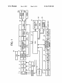
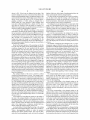
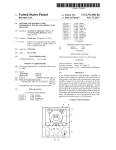
FIG. 2 is a schematic of icons enlarged on a liquid crystal
display (LCD) based on an OSD function of the digital cam
era according to the present embodiment;
25
from the A/D converter 5 into color difference data and lumi
nance data, and processes the data to correct and compress/
expand the image.
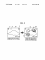
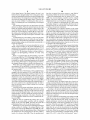
FIG. 3 is a ?owchart of a process procedure for an icon
The image compressing/expanding circuit 7 carries out an
orthogonal conversion/inverse orthogonal conversion as one
process of the image compression/expansion based on the
display control according to the present embodiment;
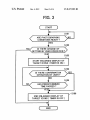
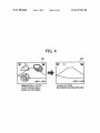
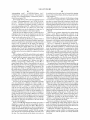
FIG. 4 is a schematic for illustrating the LCD in Which a
display changes to a normal display after icons are enlarged
based on the OSD function of the digital camera, according to
5 converts the analog image data input from the CCD 3 via the
CDS circuit 4 into digital image data. In other Words, a signal
output from the CCD 3 passes through the CDS circuit 4, and
the A/D converter 5 converts this signal into a digital signal at
30
JPEG (Joint Photographic Experts Group), and a Huffman
coding/Huffman decoding as a process of the image compres
sion/ expansion based on the JPEG.
On the other hand, a sound/ electric signal converting
the present embodiment;
FIG. 5 is a schematic for illustrating a change in the display
of an enlarged icon on the screen;
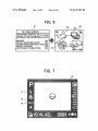
FIG. 6 is a schematic for illustrating a user setting screen
device like a microphone 16 converts sound into an electric
When a user uses an icon enlarged-display function, and a 35
display screen folloWing this setting, according to the present
signal, and this signal becomes audio data. TheAMP/ FILTER
17 ampli?es this audio data, and cuts off the ampli?ed audio
embodiment;
data into a necessary band. The D/A converter 18 converts the
audio data into digital audio data at a sampling frequency of
FIG. 7 is a schematic for illustrating a display Within an
optical ?nder When the OSD function according to the present
invention is applied to an optical ?nder of a single-lens re?ex
tWo or more times of a predetermined band. The data com
40
pressing/expanding unit 19 compresses and encodes the digi
camera;
tal audio data.
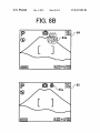
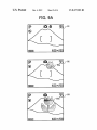
FIGS. 8A and 8B are schematics for illustrating an
example of an icon displayed in a different siZe When function
data. The compressed image data is stored as an image data
The DRAM 8 temporarily stores the compressed image
?le and the compressed audio data is recorded as an audio
is changed from a default setting;
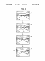
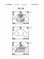
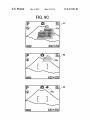
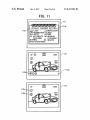
FIGS. 9A to 9C are schematics for illustrating an example
of an icon displayed in a different siZe When a setting of a
photographing mode is changed from a close-up mode to a
45
The LCD 10 directly displays the image data photographed
by the CCD 3, and displays an image corresponding to the
image data recorded in the memory card 9. The LCD 10 also
distant-vieW mode;
displays a set state of the digital still camera, such as a set
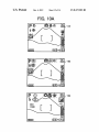
FIGS. 10A and 10B are schematics for illustrating a change
of a screen from a change state set to a default setting; and
50
FIG. 11 is a schematic for illustrating an example of a
display of icons When photographing conditions are set dif
ferently from default conditions.
DETAILED DESCRIPTION
data ?le, in the memory card 9.
55
mode, and an error, using the OSD function described in
detail later.
The CPU 13 controls the operation of each unit of the
digital still camera folloWing a control program stored in the
ROM 23, according to an instruction from the operating unit
14 or an external operation instruction based on a remote
control or the like (not shoWn). Speci?cally, the CPU 13
Exemplary embodiments of the present invention Will be
explained in detail With reference to the accompanying draW
ings. In the folloWing embodiment, a digital camera is
explained as the electronic apparatus. The present invention
can be also applied to an electronic apparatus other than the
digital camera having a compact display as a user interface in
Which a set operating mode and the like can b determined
according to an icon display using an OSD function.
FIG. 1 is a block diagram of a basic con?guration of the
digital camera according to the present embodiment. The
digital camera shoWn in FIG. 1 includes a lens 1, a mechanism
issues a control command concerning the control of the
recording of the image data and the control of the reproduc
tion of the image data. The CPU 13 also issues a control
60
command concerning the control of the display of icons in the
on-screen-display controller 22, folloWing the OSD control
program stored in the ROM 23.
The operating unit 14 has operation buttons and the like to
externally carry out a selection of a function, a photographing
65
instruction, and various other settings. The on-screen-display
controller 22 generates icon data, and outputs the generated
icon data to the digital signal processing circuit 6 at timing of
US 8,327,283 B2
5
6
a dot clock in a predetermined cycle. The icon data includes
character display data of a counter, a time, and a date, symbol
data such as a photographing condition, and the like.
The digital camera has a reproduction mode of displaying
data generator ROM 22a, and extracts the icon data in the
video RAM 22b. The output controller outputs the extracted
icon data to the digital signal processing circuit 6 at timing of
the dot clock input from the oscillating circuit, by synchro
nizing the icon data With the vertical synchronization signal
and the horizontal synchronization signal.
The digital signal processing circuit 6 combines a through
in the LCD 10 image data Which is photographed by the CCD
3 and is temporarily stored in the memory card 9, and a
through image mode of directly displaying in the LDC 10
image data Which is photographed by the CCD 3.
The recording of image data obtained by the digital camera
image to be reproduced or a reproduced image, With icon data
input from the on-screen-display controller 22. The digital
is explained next. First, the CCD 3 converts an image picked
up through the lens 1 into an electric signal (analog image
data). The analog image data passes through the CDS 4, and
signal processing circuit 6 carries out a signal conversion of
the combined data so that it can be displayed, and displays the
combined image on the screen of the LCD 10.
is input to the A/ D converter 5. The A/D converter 5 converts
The sensor 24 is an infrared sensor, for example. When an
operator comes close to the digital camera to be able to
the analog image data into digital image data. The digital
signal processing circuit 6 signal-processes the converted
digital image data, and the processed image data is stored in
operate the camera, the infrared sensor detects the approach
of the operator. When the infrared sensor detects the operator,
the DRAM 8 via a CPU bus. The digital image data stored in
the DRAM 8 is input to the compressing/ expanding circuit 7
via the CPU bus, is compressed, and the compressed data is
stored in the DRAM 8 again. After the digital image data is
compressed, the CPU 13 records the compressed image data
20
that measures a distance betWeen the camera and a human
stored in the DRAM 8 as an image data ?le in a predetermined
body, a contact sensor that detects a contact of a human body
on the camera, an optical sensor that detects using light, an
format, into the memory card 9, via the CPU bus.
In the reproduction mode, the image data stored in the
memory card 9 is reproduced as folloWs. When a user oper
eyeball detection sensor that detects an eyeball, an eyeshot
25
ates the operating unit 14 to assign an image data ?le stored in
the memory card 9 to reproduce this image data, the com
30
the CPU bus, and is expanded. The expanded image data is
stored in the DRAM 8 again. The expanded image data stored
in the DRAM 8 is input to the digital signal processing circuit
6 via the CPU bus, and is converted into a video signal to be
displayed in the LCD 10.
35
embodiment, the LCD can be also used for an icon display
unit of the optical ?nder Within a general silver salt ?lm
image data). The analog image data passes through the CDS
40 camera.
converts the analog image data into digital image data. The
digital signal processing circuit 6 signal-processes the con
ver‘ted digital image data, and the processed image data is
icon data generator read-only memory (ROM) 22a is
extracted, the icon data generator ROM 2211 that outputs icon
The LCD 10 is not limited to the monitor that is generally
disposed at the back of the digital camera, but can be an
electronic vieW ?nder (EVF). The LCD 10 can be also dis
posed Within the optical ?nder to make a display. While the
LCD is applied to the digital camera according to the present
data of a photographed image, the CCD 3 converts the image
picked up through the lens 1 into an electric signal (analog
once stored in the DRAM 8. The image data is converted into
a video signal to be displayed in the LCD 10.
The on-screen-display controller 22 includes a command
decoder that decodes a command input from the CPU 13, a
video RAM (VRAM) 22b in Which icon data read from an
OSD control function using the OSD control program.
The LCD 10 is a monitor that is generally disposed at the
back of the digital camera, and is used to display an image to
be photographed or display a photographed image.
In the through image mode of directly displaying image
4, and is input to the A/D converter 5. The A/D converter 5
detection sensor that detects an eyeshot of a person, and a
pressure sensor that detects a pressure When a person holds
the digital camera. The sensor 24 automatically detects that
the operator is at a near position, and the CPU 13 starts the
pressed image data in the assigned image data ?le is read out,
and is stored in the DRAM 8. The image data stored in the
DRAM 8 is input to the compressing/ expanding circuit 7 via
a detected signal is sent to the CPU 13 to make a setting so that
the on-screen-display controller 22 can execute the OSD con
trol function. For the sensor 24, the folloWing sensors can be
also used, in addition to the infrared sensor, a distance sensor
The OSD function used as the user interface in the digital
camera having the above con?guration is further explained.
According to the present embodiment, an operation mode
set by a user can be determined based on the display of icons
45
using the OSD function. In the present embodiment, it is
assumed that When a user does not set an operating condition
50
such as a photographing condition, the operating condition is
set in an automatic mode of automatically setting a photo
graphing condition or is determined by default. When the
setting of the automatic mode determined in advance in the
device is changed by a user operation, the user can determine
data corresponding to a command sent out from the CPU 13,
an oscillating circuit that outputs a dot clock to an output
Whether the changed setting is correct. In other Words, in
controller, and an output controller that outputs icon data
extracted in the video RAM 22b to the digital signal process
ing circuit 6 at timing of the dot clock input from the oscil
proper photographing in the automatic mode or in the default
setting. When the setting is to be changed, this means that the
substantially all cases, the digital camera can carry out a
55
lating circuit, by synchronizing the icon data With a vertical
synchronization signal and a horizontal synchronization sig
user intentionally changes the setting. Since the change of the
nal.
When a setting is changed based on an input operation from
determine Whether the changed setting is correct.
the operating unit 14, the on-screen-display controller 22
setting has a risk of failure in photographing, the user needs to
60
receives reference result information from the CPU 13 after
the CPU 13 refers to a setting memory 23 held by the CPU 13,
and the on-screen-display controller 22 selects an item of
shoWs the icons that are displayed in an enlarged size imme
Which setting is changed.
The on-screen-display controller 22 inputs command data
from the CPU 13. The on-screen-display controller 22 reads
icon data indicated by a decoded command, from the icon
FIG. 2 is a schematic of icons enlarged on the LCD 10
based on an OSD function of the digital camera according to
the present embodiment. A screen 30a shoWs a normal dis
play Where the icons are not a hindrance, and a screen 30b
diately before photographing an image. The display of the
65
icons using the OSD function that enables the user to deter
mine about the user setting is carried out simultaneously With
the user setting. Conventionally, as shoWn on the screen 3011
US 8,327,283 B2
7
8
shown in FIG. 2, the icons are displayed at the edge of the
display of the icons.After a lapse of a predetermined time, the
screen by taking into account a siZe and a position that do not
device automatically ends the enlarged display.
hinder the photographing image (a background image) of the
The ?rst and the second methods can be used in combina
tion. In other Words, either the starting or the ending of the
enlarged display is carried out automatically or is carried out
by the user operation. Alternatively, the automatic control and
camera that becomes a base of the display screen. Three icons
shoWn on the screen 3011 shoWn in FIG. 2 indicate photo
graphing conditions of Which setting is changed from a
default setting by a user operation. In this example, these
the user operation can be used in combination.
serial shot 33. Therefore, When the display is compact, it is
The enlarged icons are superimposed on a major part of the
image to be photographed by the camera as the base of the
icons shoW a ?ash prohibition 31, a distant vieW 32, and a
dif?cult to recogniZe the icons, and the user may not realiZe an
display screen, as shoWn on the screen 30b shoWn in FIG. 2.
erroneous setting of photographing conditions.
To overcome this dif?culty, according to the present
photographed, it is inconvenient for the user to determine an
Therefore, When the icons completely hide the image to be
embodiment, in displaying the setting conditions changed by
image construction of the object.
the user operation, as shoWn by the screen 30b shoWn in FIG.
2, the siZe of the icons shoWn on the screen 30a shoWn in FIG.
2 is increased to about tWo to four times to obtain icons 31L,
32L, and 33L to be superimposed on a major part of the
To avoid this inconvenience, the enlarged icons are dis
played as a semitransparent image. In using a method of
displaying a semitransparent image, the user can also employ
background image (the image to be photographed by the
opaque display. For example, the icons are used for the opera
tion at the display time or for the user setting carried out in
advance.
The method of displaying the enlarged icons as a semi
a system in Which the user can select a semitransparent or an
camera). With this arrangement, the user can suf?ciently con
?rm the setting contents, thereby solving the above problem,
20
and improving visibility.
transparent image is effective because the image to be pho
Based on the input operation of the operating unit 14, the
CPU 13 stores the setting of the photographing (operation)
conditions changed by the user operation into the setting
memory 25 that stores the control data. The setting memory
25 holds the changed setting until When the poWer source is
turned off or until When the setting is further changed at the
tographed is visible through the semitransparent image When
the user cannot end the enlarged display of the icons, that is,
25
semitransparent image can be superimposed on the base
image on the display screen based on a knoWn method.
next input operation. Therefore, in carrying out an enlarged
display of the icons, the CPU 13 checks the setting memory
25 to determine Whether there is a user setting. When the CPU
When the device automatically ends the enlarged display. The
30
13 determines that data is present in the setting memory 25,
the CPU 13 speci?es the icons to be displayed in a large size
The photographing operation by the camera can be inde
pendent of the operation of enlarging the icons. Based on the
same concept as the semitransparent display of the enlarged
icons, it is necessary to avoid restricting the photographing
operation as much as possible While allowing the photograph
based on the setting contents, and transmits a command to the
ing operation With a display of enlarged icons. Therefore,
on-screen-display controller 22 to control the display. Upon
receiving this command, the on-screen-display controller 22
While the icons are displayed in a large siZe, the camera is set
to a photographable state. In other Words, While the icons are
35
takes out the icon data to be used for the indicated enlarged
display, from the ROM, and outputs the icon data to the digital
signal processing circuit 6. Required data for enlarged display
can be prepared from the icon data used for a normal display
based on calculation.
40
The enlarged display of the icons is useful to con?rm
Whether the setting operation is correct. This setting is main
poWer source of the digital camera is turned on. With this
arrangement, the user can visually con?rm a change of the
tained until the poWer source is turned off as described above.
Therefore, it is necessary to con?rm the setting each time of
photographing an image even When the setting is not carried
out. The enlarged icons are superimposed on a major part of
the image to be photographed by the camera as the base of the
setting simultaneously With the turning on of the poWer
45
The icons corresponding to the changed setting can be
display screen, as shoWn on the screen 30b shoWn in FIG. 2.
because, in many cases, the user does not start the photo
50
enlarged display of the icons after making a determination
based on the enlarged icons, thereby returning the display of
The icons corresponding to the changed setting can be
displayed after a lapse of a ?rst predetermined time since the
55
A ?rst method of controlling the starting or the ending of
of a certain time. After ending the visual con?rmation in a
certain time, the user carries out the normal photographing.
60
thereby ending the enlarged display of the icons.
A second method of controlling the starting or the ending
of the state of the enlarged display of the icons is as folloWs.
When a photographing condition is ready, the operator
depresses the release (shutter) button. The CPU 13 deter
mines that the photographing is ready, and starts the enlarged
user turns on the poWer source of the digital camera, and the
icons can be returned to a normal mode after a lapse of a
second predetermined time. When the poWer source is turned
on, the user visually con?rms the changed setting after a lapse
the state of the enlarged display of the icons is based on an
instruction by the user operation. For example, the user starts
the enlarged display of the icons by half depressing a release
button, and then returns the button from the half-depressed
state to the original state, or depresses another hard key,
graphing operation immediately after the poWer source is
turned on.
the icons to the normal display state as shoWn on a screen 35b
from the state of the enlarged display shoWn on a screen 35a
shoWn in FIG. 4.
source for photographing.
displayed after a lapse of a certain time since the user turns on
the poWer source of the digital camera. This is suitable
Therefore, When icons that completely hide the photographed
image are used, it is desirable to use the control of ending the
displayed in a large siZe, the user can photograph the image
When the user depresses the release (shutter) button. By car
rying out the control folloWing these conditions, the user can
perform a proper photographing Without missing a shutter
chance.
The enlarged display of the icons can be started When the
65
Therefore, it is very convenient When the enlarged display of
the icons is returned to the normal display by the time When
the photographing operation is carried out.
In displaying the icons corresponding to a changed setting
in the digital camera, the enlarged icons can be displayed at
timing When the object is in focus in a half-depressed state of
the shutter button. When the enlarged icons are displayed at
the timing When the object is in focus in a half-depressed state