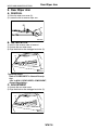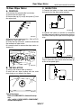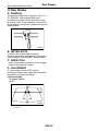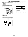
1
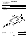
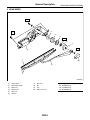
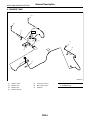
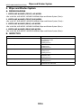
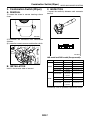
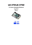
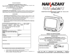
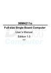
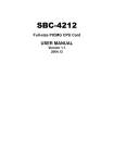
2004 IMPREZA SERVICE MANUAL
QUICK REFERENCE INDEX
BODY SECTION
This service manual has been prepared
to provide SUBARU service personnel
with the necessary information and data
for the correct maintenance and repair
of SUBARU vehicles.
This manual includes the procedures
for maintenance, disassembling, reassembling, inspection and adjustment of
components and diagnostics for guidance of experienced mechanics.
Please peruse and utilize this manual
fully to ensure complete repair work for
satisfying our customers by keeping
their vehicle in optimum condition.
When replacement of parts during
repair work is needed, be sure to use
SUBARU genuine parts.
All information, illustration and specifications contained in this manual are
based on the latest product information
available at the time of publication
approval.
FUJI HEAVY INDUSTRIES LTD.
HVAC SYSTEM
(HEATER, VENTILATOR AND A/C)
AC
HVAC SYSTEM (AUTO A/C)
(DIAGNOSTICS)
AC(diag)
AIRBAG SYSTEM
AB
AIRBAG SYSTEM (DIAGNOSTICS)
AB(diag)
SEAT BELT SYSTEM
SB
LIGHTING SYSTEM
LI
WIPER AND WASHER SYSTEMS
WW
ENTERTAINMENT
ET
COMMUNICATION SYSTEM
COM
GLASS/WINDOWS/MIRRORS
GW
BODY STRUCTURE
BS
INSTRUMENTATION/DRIVER INFO
IDI
SEATS
SE
SECURITY AND LOCKS
SL
SUNROOF/T-TOP/CONVERTIBLE TOP
(SUNROOF)
SR
EXTERIOR/INTERIOR TRIM
EI
EXTERIOR BODY PANELS
EB
G1870GE6
2004 IMPREZA SERVICE MANUAL
QUICK REFERENCE INDEX
BODY SECTION
CRUISE CONTROL SYSTEM
CC
CRUISE CONTROL SYSTEM
(DIAGNOSTICS)
CC(diag)
IMMOBILIZER (DIAGNOSTICS)
IM(diag)
G1870GE6
WIPER AND WASHER SYSTEMS
WW
1.
2.
3.
4.
5.
6.
7.
8.
9.
10.
11.
12.
Page
General Description ....................................................................................2
Wiper and Washer System .........................................................................6
Combination Switch (Wiper)........................................................................7
Wiper Blade.................................................................................................9
Washer Tank and Motor............................................................................11
Front Wiper Arm........................................................................................12
Front Wiper Motor and Link.......................................................................13
Front Washer Nozzle ................................................................................15
Rear Wiper Arm ........................................................................................16
Rear Wiper Motor......................................................................................17
Rear Washer .............................................................................................18
Wiper Control Relay (Wagon Model) ........................................................19
General Description
WIPER AND WASHER SYSTEMS
1. General Description
A: SPECIFICATIONS
Front wiper motor
Rear wiper motor
Input
Input
Pump type
Input
Pump type
Input
Front washer motor
Rear washer motor
12 V — 72 W or less
12 V — 42 W or less
Centrifugal
12 V — 36 W or less
Centrifugal
12 V — 36 W or less
B: COMPONENT
1. FRONT WIPER
(4)
T1
T1
T1
T2
(5)
T2
T1
(3)
(1)
(1)
(3)
(2)
(2)
WW-00140
(1)
(2)
(3)
Wiper rubber
Wiper blade ASSY
Wiper arm
(4)
(5)
Wiper link
Wiper motor
WW-2
Tightening torque: N·m (kgf-m, ft-lb)
T1: 6.0 (0.61, 4.4)
T2: 20 (2.0, 14.5)
General Description
WIPER AND WASHER SYSTEMS
2. REAR WIPER
T1
(5)
T1
(6)
(7)
T2
(8)
(9)
T3
(4)
(1)
(10)
(3)
(2)
WW-00058
(1)
(2)
(3)
(4)
(5)
(6)
Wiper rubber
Wiper blade ASSY
Wiper arm
Wiper motor
Spacer A
Cushion
(7)
(8)
(9)
(10)
Spacer B
Nut
Cap
Wiper arm cover
WW-3
Tightening torque: N·m (kgf-m, ft-lb)
T1: 6.0 (0.61, 4.4)
T2: 7.5 (0.76, 5.5)
T3: 8.0 (0.82, 5.9)
General Description
WIPER AND WASHER SYSTEMS
3. WASHER TANK
(1)
(1)
(2)
T
(4)
(3)
(5)
(7)
(1)
(2)
(7)
(6)
(2)
WW-00142
(1)
(2)
(3)
(4)
Washer nozzle
Washer hose
Washer tank
Washer tank cap
(5)
(6)
(7)
Front washer motor
Rear washer motor
Grommet
WW-4
Tightening torque: N·m (kgf-m, ft-lb)
T: 6.0 (0.61, 4.4)
General Description
WIPER AND WASHER SYSTEMS
C: CAUTION
• Reconnect the connectors and hoses securely.
After reconnecting, confirm that each function operates normally.
• Be careful that wiring harnesses of airbag system pass near electrical parts and switches.
• Wiring harnesses and connectors of all airbag
system are yellow color. Do not use a tester on
these circuits.
• Care must be taken when installing the piping
hose so that no bending, jamming, etc. are caused.
• If even a little oil or grease such as silicon oil gets
in the tank and washer passages, an oil film easily
forms on the glass, causing the wiper to chatter and
judder. Therefore, be careful not to let this happen.
WW-5
Wiper and Washer System
WIPER AND WASHER SYSTEMS
2. Wiper and Washer System
A: WIRING DIAGRAM
1. WIPER AND WASHER (FRONT) LHD MODEL
<Ref. to WI-256, LHD MODEL, WIRING DIAGRAM, Wiper and Washer System (Front).>
2. WIPER AND WASHER (FRONT) RHD MODEL
<Ref. to WI-257, RHD MODEL, WIRING DIAGRAM, Wiper and Washer System (Front).>
3. WIPER AND WASHER (REAR) LHD MODEL
<Ref. to WI-258, LHD MODEL, WIRING DIAGRAM, Wiper and Washer System (Rear).>
4. WIPER AND WASHER (REAR) RHD MODEL
<Ref. to WI-259, RHD MODEL, WIRING DIAGRAM, Wiper and Washer System (Rear).>
B: INSPECTION
Symptom
Wiper and washers do not operate.
Wipers do not operate in LO or HI.
Wipers do not operate in INT.
Washer motor does not operate.
Wipers do not operate when washer switch is ON.
Washer fluid spray does not operate.
Repair order
(1) Wiper fuse (F/B No. 14, 15)
(2) Combination switch
(3) Wiper motor
(4) Wiring harness
(1) Combination switch
(2) Wiper motor
(3) Wiring harness
(1) Combination switch
(2) Wiper motor
(3) Wiring harness
(1) Washer switch
(2) Washer motor
(3) Wiring harness
(1) Washer motor
(2) Wiring harness
(1) Washer motor
(2) Washer hose and nozzle
WW-6
Combination Switch (Wiper)
WIPER AND WASHER SYSTEMS
3. Combination Switch (Wiper)
C: INSPECTION
A: REMOVAL
• Inspect the continuity between each connector
terminal.
1) Loosen the screw to remove steering column
cover.
WW-00004
2) Disconnect the connectors from combination
switches.
3) Loosen the screw to remove combination switch.
9 8
18 17
7 6 5 4 3
16 15 14 13 12
2 1
11 10
WW-00046
LHD model and RHD model (Europe model):
WW-00045
B: INSTALLATION
Install in the reverse order of removal.
Switch position
OFF
INT
FRONT
LO
HI
Washer ON
Washer ON
REAR
OFF
ON
Washer ON
Terminal No.
7 and 16
7 and 16
7 and 17
8 and 17
2 and 11
2 and 10
10 and 12
2 and 12
—
2 and 10
2 and 10
10 and 12
2 and 12
Standard
Less than 1 Ω
Less than 1 Ω
Less than 1 Ω
Less than 1 Ω
Less than 1 Ω
Less than 1 Ω
More than 1 MΩ
Less than 1 Ω
Less than 1 Ω
If continuity is not as specified, replace the switch.
WW-7
Combination Switch (Wiper)
WIPER AND WASHER SYSTEMS
RHD model (Except Europe model):
Switch position
OFF
INT
LO
FRONT
HI
Washer ON
Washer ON
REAR
OFF
ON
Washer ON
Terminal No.
3 and 12
3 and 12
3 and 11
2 and 11
8 and 17
8 and 16
16 and 18
8 and 18
—
8 and 18
8 and 16
16 and 18
8 and 18
If continuity is not as specified, replace the switch.
• Intermittent operation inspection
1) Turn the wiper switch to INT.
2) Adjust the intermittent control switch to MAX.
3) Apply battery voltage to switch terminals 16 and
2.
4) Inspect the voltage of combination switch terminals.
Standard
Less than 1 Ω
Less than 1 Ω
Less than 1 Ω
Less than 1 Ω
Less than 1 Ω
Terminals
LHD model and RHD model (Europe model)
No. 7 — No. 2:
RHD model (Except for Europe model)
No. 3 — No. 8:
Less than 1 Ω
More than 1MΩ
Less than 1 Ω
Less than 1 Ω
(A)
(B)
(F)
(C)
(G)
(H)
(F)
(D)
(G)
(I)
(F)
(E)
(G)
(J)
WW-00053
(A)
(B)
(C)
(D)
Switch position
Voltage
MIN.
MAX.
(E)
(F)
(G)
(H)
Non variable type
12 V
0V
Approx. 2 sec.
If operation is not as specified, replace the switch.
WW-8
(I)
(J)
16±6 sec.
3±1 sec.
Wiper Blade
WIPER AND WASHER SYSTEMS
4. Wiper Blade
D: ASSEMBLY
A: REMOVAL
1. METAL TYPE
While pushing the locking clip (A) up, pull out the
blade from arm to arrow direction.
1) Insert the wiper rubber onto blade so that the
stopper is in the position shown.
3
2
(A)
2
3
1
WW-00064
WW-00049
B: INSTALLATION
2) Make sure the wiper rubber is securely fastened
to the pull stopper (A).
1) Install in the reverse order of removal.
2) Confirm that the clip is locked securely.
C: DISASSEMBLY
1. METAL TYPE
Pull on the side (A) of wiper rubber stopper, and
then remove the rubber from blade assembly.
WW-00037
WW-00009
2. RESIN TYPE
Pull the wiper rubber top slightly from the stopper
(A) and pull it out fully.
(A)
WW-00143
WW-9
Wiper Blade
WIPER AND WASHER SYSTEMS
2. RESIN TYPE
A
D
B
C
WW-00144
1) Insert the wiper rubber through the claw (B).
3) Insert the wiper rubber into the claw (A).
A
A
B
WW-00147
WW-00145
2) Insert the wiper rubber top until it protrudes
about 20 mm (0.79 in) from the stopper (D).
20mm ( 0.79 in. )
D
E: INSPECTION
1) When the wiper does not perform well, inspect
the following:
• Make sure the movable part of the blade assembly moves smoothly.
• Make sure the wiper rubber is not deformed or
damaged.
2) Replace them with new parts if damaged.
WW-00146
WW-10
Washer Tank and Motor
WIPER AND WASHER SYSTEMS
5. Washer Tank and Motor
E: INSPECTION
A: REMOVAL
Apply battery voltage to the connector terminal of
the washer motor and make sure the motor operates.
1) Open the hood.
2) Disconnect the ground cable from battery.
3) Remove the two bolts, hose and connector, and
then remove the tank.
WW-00013
WW-00011
B: INSTALLATION
Install in the reverse order of removal.
Tightening torque:
6.0 N·m (0.61 kgf-m, 4.4 ft-lb)
C: DISASSEMBLY
Pull out the washer motor from tank.
WW-00012
D: ASSEMBLY
1) Assemble in the reverse order of disassembly.
2) Confirm that water does not leak from installation area of motor.
WW-11
Front Wiper Arm
WIPER AND WASHER SYSTEMS
6. Front Wiper Arm
C: ADJUSTMENT
A: REMOVAL
NOTE:
The positions for RHD model are symmetrically opposite.
Operate the wiper once. Align the wiper blade to
the ceramic print point mark (A) of front window
pane.
NOTE:
The positions for RHD model are symmetrically opposite.
1) Open the hood.
2) Remove the cap.
3) Loosen the nut to remove arm.
(A)
WW-00048
WW-00071
B: INSTALLATION
NOTE:
The positions for RHD model are symmetrically opposite.
1) Install in the reverse order of removal.
2) Operate the wiper once.
3) Align the wiper blade to the ceramic print point
mark (A) of front window pane.
(A)
WW-00048
Tightening torque:
Refer to COMPONENT in General Description.
<Ref. to WW-2, FRONT WIPER,
COMPONENT, General Description.>
WW-12
Front Wiper Motor and Link
WIPER AND WASHER SYSTEMS
7. Front Wiper Motor and Link
A: REMOVAL
NOTE:
The positions for RHD model are symmetrically opposite.
1) Disconnect the ground cable from battery.
2) Remove the cowl panel. <Ref. to EI-32, REMOVAL, Cowl Panel.>
3) Disconnect the connector of motor.
4) Loosen the bolts to remove wiper link.
Tightening torque:
Refer to COMPONENT in General Description.
<Ref. to WW-2, FRONT WIPER,
COMPONENT, General Description.>
C: INSPECTION
1) When the battery is connected to the terminal of
connectors, confirm that the motor operates at low
speed.
3 2 1
5 4
WW-00019
2) When the battery is connected to the terminal of
connectors, confirm that the motor operates at high
speed.
WW-00150
5) Loosen the bolts and nuts to remove motor.
3 2 1
5 4
WW-00020
WW-00157
B: INSTALLATION
1) Connect the battery ground cable to battery.
2) To confirm that the motor is at auto stop position,
connect the harness to motor and turn the wiper
switch ON/OFF once.
3) Disconnect the ground cable from battery.
4) Tighten the nut where rod (A) and link plate (B) is
aligned in a straight line.
(A)
3) Connect the battery to terminals of connector,
and then remove the terminal connection with motor rotated at low speed, and stop the wiper motor
through operation.
3 2 1
5 4
(B)
WW-00021
WW-00153
5) Install in the reverse order of removal.
WW-13
Front Wiper Motor and Link
WIPER AND WASHER SYSTEMS
4) Connect the battery and confirm that the motor
stops at automatic stop position after the motor operates at low speed again.
3 2 1
5 4
WW-00022
WW-14
Front Washer Nozzle
WIPER AND WASHER SYSTEMS
8. Front Washer Nozzle
A: REMOVAL
1) Remove the washer hose from washer nozzle.
2) Open the clips on the underside of hood with a
thin screwdriver or other tool, and then remove the
washer nozzle.
WW-00023
B: INSTALLATION
1) Install in the reverse order of removal.
2) Adjust the position of the washer liquid sprayer.
<Ref. to WW-15, ADJUSTMENT, Front Washer
Nozzle.>
C: INSPECTION
• Make sure the nozzle and hose are not clogged.
• Make sure the hose is not bent.
D: ADJUSTMENT
NOTE:
This adjustment position is for left-handed vehicle.
Carry out left-right symmetry for adjustment positions for right-handed vehicle.
1) Turn the wiper switch to OFF position.
2) When the vehicle stops, adjust the washer injection position as shown in the figure.
Injection position:
A: 350 mm (13.78 in)
B: 162 mm (6.38 in)
C: 300 mm (11.81 in)
D: 500 mm (19.69 in)
A
A
B
B
C
D
(1)
WW-00111
(1) Nozzle
WW-15
Rear Wiper Arm
WIPER AND WASHER SYSTEMS
9. Rear Wiper Arm
A: REMOVAL
1) Raise the wiper arm cover (A).
2) Loosen the nut to remove wiper arm.
WW-00025
B: INSTALLATION
1) Install in the reverse order of removal.
2) Operate the rear wiper once.
3) Align the blade to rear defogger heat wire (A).
(A)
WW-00154
Tightening torque:
Refer to COMPONENT in General Description.
<Ref. to WW-3, REAR WIPER, COMPONENT,
General Description.>
C: ADJUSTMENT
1) Operate the rear wiper once.
2) Align the blade to rear defogger heat wire (A).
(A)
WW-00154
WW-16
Rear Wiper Motor
WIPER AND WASHER SYSTEMS
10.Rear Wiper Motor
C: INSPECTION
A: REMOVAL
1) Connect the battery to wiper motor connector
and confirm that the wiper motor operates.
1) Disconnect the ground cable from battery.
2) Remove the rear wiper arm.
3) Remove the cap (A), nut (B) and spacer (C) from
rear wiper shaft.
2 1
4 3
WW-00030
WW-00027
4) Remove the rear gate lower trim. <Ref. to EI-52,
REMOVAL, Rear Gate Trim.>
5) Unclip the clip of harness, and then disconnect
the connector of wiper motor.
6) Loosen the bolts to remove the wiper motor assembly (A).
2) Connect the battery to terminal of connector,
and then remove the terminal connections with motor rotated, and stop the wiper motor through operation.
2 1
4 3
(A)
WW-00031
3) Connect the battery and confirm that the motor
stops at automatic stop position after the motor operates at low speed again.
WW-00155
B: INSTALLATION
1) Install in the reverse order of removal.
2) Install the rear wiper cushion with the arrow
mark facing up, as shown in the figure.
2 1
4 3
WW-00032
WW-00029
Tightening torque:
Refer to COMPONENT in General Description.
<Ref. to WW-3, REAR WIPER, COMPONENT,
General Description.>
WW-17
Rear Washer
WIPER AND WASHER SYSTEMS
11.Rear Washer
A: REMOVAL
1) Remove the high-mount stop light. <Ref. to LI27, REMOVAL, High-mounted Stop Light.>
2) Remove the washer hose from washer nozzle.
3) Open the clips on the underside of hood with a
thin screwdriver or other tool, and then remove the
washer nozzle.
WW-00023
B: INSTALLATION
1) Install in the reverse order of removal.
2) Adjust the position of the washer liquid sprayer.
<Ref. to WW-18, ADJUSTMENT, Rear Washer.>
C: INSPECTION
• Make sure the nozzle and hose are not clogged.
• Make sure the hose is not bent.
D: ADJUSTMENT
1) Turn the wiper switch to OFF position.
2) When the vehicle stops, adjust the washer injection position as shown in the figure.
Injection position:
A: 39 mm (1.54 in)
B: 72°
(1)
A
B
WW-00054
(1) Nozzle
WW-18
Wiper Control Relay (Wagon Model)
WIPER AND WASHER SYSTEMS
12.Wiper Control Relay (Wagon
Model)
3) Measure the voltage when the wiper relay is operated.
A: REMOVAL
1) Disconnect the ground cable from battery.
2) Remove the right quarter lower trim. <Ref. to EI48, REMOVAL, Rear Quarter Trim.>
3) Loosen the nut to remove control unit.
(1)
(2)
12 V
ON
0V
(3)
WW-00036
(1) Switch position
(2) Voltage
(3) 9±2 sec.
If operation is not as specified, replace the switch.
WW-00156
B: INSTALLATION
Install in the reverse order of removal.
C: INSPECTION
1) Disconnect the connector from wiper control relay.
2) Connect the positive (+) lead from the battery to
terminal 8 and the negative (−) lead to terminal 6.
Connect the positive (+) lead from the voltmeter to
terminal 3 and the negative (−) lead to ground.
4
3
2
1
8
7
6
5
WW-00035
WW-19
Wiper Control Relay (Wagon Model)
WIPER AND WASHER SYSTEMS
WW-20