1
PAGE
SECTION1
TEST
ELECTRICAL
EQUIPMENT
1 . 1 T H R U1 . 3
sEciloN 2
ECHANICAL
ELECTRICAL.M
2.1 THRU2.7
TROUBLESHOOTING
SECTION3
SERVICEPROCEDURES 3'1 THRU3-26
4
sEcTroN
PRE.INSTALLATION
&
INSTALLATION
4.1 THRU4-10
SECTION5
WARRANTY&
PARTS
REPLACEMENT
5.1 THRU5.2
SECTION6
SPECIFICATIONS
6.1 THRU6.9
7
sEcTroN
ELECTRICAL
SCHEMATICS
7.1 THRU7.119
38767
38766
3-12302
2-13323
3-4652
3-11353
59128
. : \
-+
- t
I
I
59).2
59133
59134
\
2-rr2e4
3- 4630
3- 3736
2-1r294
3-13272
Blodef or sow
Replocementdrill
H o l es o ww i t h d r i l l
Extensionfor sow
Vent kit - stondord 4'r ( I 0. | 5cm) kit contoirs three 59| 30 4" x 24"
( l 0 . l 6 c m x 6 0 . 9 5 c r no) l u m i n u mp i p e s ,t w o 5 9 1 3 14 " ( l 0 . l 5 c m ) o l u m i n u me l b o w so n d
one 591294" ( 10.l5cm) vent hood
Vent hood- 4" ( l0.l 6cm) wide-mouth
59t29
5 9 t 3 0 Aluminumpipe - 4" x 24" ( 10.l5cm x 50.95cm)
5 9 r 3 1 A l u m i n u me l b o w- 4 ' ' ( l 0 . l 5 c m )
5 9 t 3 3 Aluminumwindowplote - 12"x 18"(30.48cmx 45.72cm)
59134 A l u m i n u mw i n d o wp l o t e - 1 5 "x 2 0 " ( 3 8 . l O c mx 5 0 . 8 0 c m )
5 9 1 3 5 Vent duct ossembly- 18"(45.72cm)to 30" (75.20cm)long
5 9 r 4 3 F l e x i b l eo l u m i n u mv e n t k i t - i n c l u d e so n e 4 " ( l 0 . l 6 c m ) v e n t h o o d ,t w o 4 " ( l 0 . l 5 c m )
clompsond one 4" ( 10.| 6cm)dio. x 8' (2.44m)f lexiblevent duct
59144 Rectongulorvent kit with roundodopter
38t19
38180
38766
3876l
59t28
2-11294 Screw - for exhoustduct kit
- for exhoustdeflector kit
2-13323 Fostenerfor exhoustduct kit
3-3136 Exhoustdeflector kit for nonventeddryer
3-4353 F l e x i b l e o l u m i n u mv e n t d u c t - 4 " x 3 2 " ( l 0 . l 5 c m x 8 l . 2 8 c m ) l e n g t hs t r e t c h e st o 8 '
3-4530
3-4652
3 - rI 3 s 3
3-t2302
3-13272
(2.44m)
C l o m pf o r f l e x i b l ed u c t
Exhoustduct kit for side ond bottornvenfing
Docronlint bog
lnsulotionf or exhoustduct kit
Brocketfor exhousideflector
-
\-
M/\YTAG
@
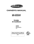
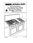
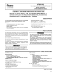
1 ControlPanelAssemblyComponents
2 Front Paneland Door
3 Tumblsrand RelatedComponents
4 Blower,Regulatingand Cool DownThermostats
5 DriveMotorand ldler
6 HeatingElement
7 GasValve
8 Gabinetand Top Cover
I
s _ra
\-
d\
'lq,
T
\-l- x
I
.*\F\
(r Tf
.a\
I*a ^-,
l
I
\!rr'ir
-
ffifl1 s^-
I
.-4
\< {'+
e
\
* \ '
A
0
I
fr
<---.
s$a
"s
s0
|e
IR
o
t$
J
s,o
3g
#6?{-a
Secfnon1
Tcsf
Elccfnnaol
Equf,pnncnf
\-
MAYTAG
oHMS(RESISTANCE
MEASUREMENTS)
resistance
be certainthe unitis disWhenchecking
power
supply.Failureto do so
fromits
connected
w i l l r e s u l ti n m e t e rd a m a g ew h e n p e r f o r m i n g
readings,
wiresshouldbe dischecks.Foraccurate
fromboth sidesof the component.
connected
SET METER FOR USE AS FOLLOWS:
C ,..,,*{r
\-
ll
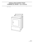
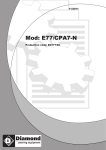
The Maytag appliancetest meter is most effective
when used to detect open or closedcircuitsin an
electricalcomponent.This method of testing is
"continuity
often referredto as
testing" and is the
easiestmeansof checkinga part.
A continuitycheckcan be safelymadeonly afterthe
unit beingcheckedhas been disconnectedfrom its
electricalsupplyand after you have removedwires
from the terminalsof the part beingtested.Following manualactivationof the part (if required)and
after the meterhas beenset on an ohms scale,the
probes of the test meter are placed on the respec"O"
tive terminals.Needlemovementto the
end of
the scalewouldindicatecontinuitythroughthe part.
No needlemovementwould indicateno continuity
and a probableinoperativepart.
In general,when checking for continuity,needle
deflectionindicatesa closedcircuitand no needle
deflectionwould indicatean open circuit.
testprobestogether
meterby touching
1. Calibrate
"0"
dialuntilmeterreads
and turningadjusting
whenever
on greenscale.Recheckcalibaration
(Replace
batteryif dialwillnot
scaleis changed.
to "0".)
bringmeterreading
2. Selectthe scalemosteasilyreadandplacetest
Whenchecking
probeson respective
terminals.
a switchthe readingwouldnormallybe either
openor closed.A readingof 70 on the R x 10
scalewouldfor examplebe 700 ohms resistance.
values
Thefollowing
chartshowstypicalresistance
Maytag
found
on
dryfor someof the components
ers.
HeatingElement
1 0 . 2 3o h m s
Gas Valve
radiantsensorand igniterwires.MeaDisconnect
sureacrossigniterwiresor igniterplugfromvalve
to get a resistancevalueof 425-450ohms.
of
Measure
acrosssensorwiresto geta resistance
450-475ohms.
DriveMotor
Redterminalto Grayterminal
1 . 5o h m s
'
1-1
In order to measurethe individualwindingsthe red
and gray wireswill haveto be pulledoff of the start
switch.
2.25ohms
3 ohms
Run windingonly
Start windingonly
Glow Bar lgniter
Becauseof the make-upof the igniter,the resistancewill vary over a ratherwide range.Values
from180ohmsto 400ohmswouldbe typicalwith
an igniterat roomtemperature.
Shut-OffSolenoid50 ohms-
ElectronicControlModels
55 ohms
arenot meantto be usedas the
Theseresistances
is
whethera component
values
to
determine
exact
goodor bad.Theyare providedso that you may
that you can seein
havean ideaof the resistance
Maytag
dryers.
on
testingcomponents
probe(Part No. 38562)
accessorytemperature
directlyin the lint filteropening.Cyclingof the
can actuallybe observedas can the
thermostats
air.
of the exhausted
temperature
SET UP METER FOR USE AS
FOLLOWS:
knobto TEMP.
1. Turnselector
probe
leadof temperature
negative
Insert
black
2.
(black).
marked
intosocket
probeinto
leadof temperature
3. Insertredpositive
(red).
+
socketmarked
4. To calibratemeter,touchblackplug from red
leadandturncalipositive
leadto blacknegative
withCAL.
aligns
needle
until
brationdial
read
blue scaleon
to
use
is
ready
5. Probe
TEMP.
marked
meterface
CHECKS
VOLTAGE
For the most part thesecheckswillconsistof taking
readingsat the wall receptaclein orderto determine
the availabilityof voltage to the product.Voltage
checks on individualcomponentsof a productare
due to the possibilityof electrical
not recommended
shock. Componentpart testing is best accomplishedthrough continuitychecks with a 38559
Maytag appliancetest meter.
NOTE: Use of the meter on voltage higher than
indicatedrange may cause permanentdamageto
the meter.To preventdamagefirst select highest
rangeand then lower for readingswhich fall within
the lower scale.
SETUP METERFORUSEAS
FOLLOWS:
1. Turn selectorknobto desiredmeterfunctionand
appropriaterange.
2. Plug black lead into socket marked- (black).
3. Plug red lead into socket marked+ (red).
4. Placetest leadsinto receptaclein orderto determine voltageavailable.
READINGS
TEMPERATURE
RANGE(50'F. TO 300'F.)
readings
can be takenat
Dryer- Air temperature
the filterand placingthe
the lintfilterby removing
1-2
"normal"current
Eachcircuitin an appliancehas a
draw which is an indicationof the performanceof
that circuit.Currentdraw levelsless than or more
The clampthan normalgive cluesto malfunctions.
o n a m m e t e r m e a s u r e st h e s e c u r r e n t sw i t h o u t
breakingthe circuitby measuringthe strengthof the
magneticfield developedaround each conductor.
Currentis read by separatingthe conductorsand
clampingthe jaws of the ammeteraroundeachconductor on which currentis to be read. Low amperage readingsindicateproblemssuch as damaged
heatingelements,excess belt slippage,etc. High
amperagereadingsindicatethe unit beingtestedis
operatingunderan increasedmechanicalor electri-
cal load.Worn parts or low voltagewill show up as
low amperagereadings.
mannerdetermineswhetheror not it will run independentlyof other electricalcomponents.
NOTE: Overloadson a circuitbreakeror fuse can
be tracedto the productbeingtested or the circuit
breaker(or fuse)by checkingthe product'scurrent
draw. lf the amperagereadingis less than the
breakerreading,the breakeror fuse box is at fault.
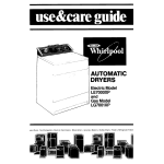
Two test leads are requiredto check operationof
the drive motor. To check the motor for runnino.
hook uo test cord as shown.
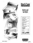
U SE O F A MME T E RON D R Y E R
Therearetwocurrents
of concern
to usin anelectric dryer;the heatingelementcurrentand the drive
motor current.Thesecurrentscan be measuredby
"splitline
useof a
cord"extensionfor the dryercord
or by attachingthe ammeter to the respective
powerlinewiresat the dryerterminalblock.Current
measuredshould be 21 amps on the heatingelement side of the line,24 amps on the drive motor
side of the lineand 4 amps on the centeror neutral
line.
-
d/d:__.\\
\
it \ '-\
.)
The motor test cord may be used to electrically
c h e c ko p e r a t i o no f t h e d r i v e m o t o r w h i l e s t i l l
installed
in the unit.Testing of the motor in this
Locationof terminalson motor may vary from drawing.
HEATCONTACTS
CHECKING
MOTORCENTRIFUGAL
SWITCH
1. Disconnectdryer power source.
2. Gainaccessto motor and removeblueand black
leads from motor switch.
3. Use either of the followingtest methods using
appropriatecaution.
A. Live test - use caution
1. Usinga2-1110wiringcoupler,connectblue
and blackwires removedfrom motor switch.
switch.
2. Reconnectdryer to power and set for heat
cycre.
3. Startdryer,if heatis produced,replacemotor
switch on motor. lf no heat, continueadditionalcircuitchecks.
B. ContinuityCheck
(lnsulatewires removedfrom motor switch.)
1. Usingclipadapterssuppliedwith the Maytag
ApplianceTest Meter,attachmeterprobesto
the blue and blackmotor switchterminals.
2. Arrangeprobe leads away from any moving
parts and set meter on RX1 range.
3 . Reconnectdryer to power source and start
dryer, continuityon meter indicatesgood
switch. No continuity,replacemotor switch
or motor.
4 . Opendoor to stop dryer.When motor stops,
m o t o r s w i t c h c o n t a c t sm u s t o p e n , i f n o t
replaceswitch or motor.
WH OR GY
PROTECTOR':
.,.,d]!LE
1-3
Secfflon2
cchonnc@
Eilecfnnaoil=A
Tfnoub[cshoofing
MAYTAG
Il|'lttNOT
RUN
Dryerwon't start or run.
All wires are hooked
up to their corresponding
terminals.
Doorswitch
Dryer is pluggedin.
Blown fuse or circuitbreaker.
Push-to-start
switch.-Timer.
Time and auto dry
models.
Drivemotor.
Drivemotor runs -
drum won't turn.
Be|tofforbroken.-Motorpu||ey|ooseor9ff.-|d|ertensionspring.-|d|erpu||ey.
Dryerruns a few minutesand then stops Motor overloadprotectoropens.
Lint build-uparounddrive-Low
motor.
voltage
Check cool down thermostat-
Blower impeler btocked.-Drive
motor.
D712.
2-1
Dryerblows fuses or trips circuit breaker.
E L EC T R I CM O D EL S
GAS MODELS
The amperagereadingsare
at 240 volts. One line will be 24
amos and the other linewill be
21 amos.The neutrallinewill be
at 4.5 amps. lf you have the
above amperagereadings,the
problemis not the dryer. Check
the fuse box, circuitbreakeror
housewiring.
Duringignitionthe dryerwill draw
7 amps.With the burneron, the
dryerwill draw 4.5 amPs.lf the
dryer is drawingthe above
amperageand the fuse blows,
the problemis not the dryer.
Checkthe fuse box, circuit
@
Snortebheatinoelement.
Incorrectwiring or a wire shorting
to ground.
Drive motor.
NOT
DRY
U1IIIL
Dryerwon't heat (motorruns).
GAS MODELS
E L EC T R I CM O D E L S
'
Gas available.
Blown fuse or trippedcircuit
breaker.
II
II
lgniter.
I
Open heatingelement.
Radiantsensor.
II
Gas valve.
Hi-limitthermostat.
Timer
auto dry
I
thermostat.-Temperature selectorswitch.
Regulating
and time
models.
Cycleselectorswitch
D608,D808,D710.
Drive motor start switch
lmproperDrying-
ClothesWrinkled-
Harsh-
Takingtoo long
Lint filteris clean.-Restriction in exhaust.-Exhaust hood door stuck.-Exhaust too long.--1
\y
2-2
Poormake-up
drumspeed.-Blower
air.-lnsorrect
Adjustmotorpulley
pulley.
or wrono
wrongmotoroullev.
Shortedheating
element- electric
dryersonly.
impeller
bound.-Be
dryer.
Customeroverloading
sureelement
or gas valvecycles
on and off.
Check clothinglabels
for fabriccontent.
WIttNOT
OFF
SI|UT
Time Dry Models
Timermotor- Timer
Auto Dry Models
Set timer for time dry. Check
voltageacross timer motor. lf -off,
timer will not advance,replace
timer.
When valve or elementcycles
should have power to
Dryer cyclingon hi limit thermostat. Check following.
timermotor.lf not, proceed
with nextcheck.
Lint filterclean.-Restriction in exhaust.-Exhaust hood door 5lv6t1.-fxhaust too long
Regulating
thermostat.-Customer is overloading
dryer.
W O N ' TS H U TO F F O N A I R F L U F F " - D 5 1 O
Dryer will shut off on air fluff
only when the timer is set to
Time Dry.
E L E C T R O N T C O N T R O LM O D E L S D 6 0 8 , D 7 1 0 , D 7 1 2 , D 8 0 8 , D 8 1 0
DRYERWON'TSHUTOFF."SOLENOID
NEVERENERGIZES.''
D608,D808
Be sure dryer heats,dries
Check for loose wires and be
that all wires are con- -tllus
clothesand conditionrelatesto-sure
nectedto correctterminals.
malfunctionof contro..
Sensorcircuit.DisconnectWH/
at sensorcoupler.Set
dial to damp dry. lf dryer
shuts off within 60 seconds,
difficultyis causedfrom
leakagein sensorcircuit.
2-3
Edgeboardconnectorwith
Cycle selectorswitch. See
Shut-offsolenoid.Unplugdryer
-Electrical
Set dryer to regular
Sectionfor switch-cdpacitor.
and check for continuity
start
unit.While
cycle
and
tests.
betweenthe two solenoidteris
observe
dryer
operating
minals.
neon bulb.lf neon bulb flickers,
I
replaceedgeboardconnector
Electroniccontrol board.
with caoacitor.
D710,D712,and D810 Dryers,PermanentPress and Regular.
Be sure dryer heats,dries
clothesand conditionrelatesto malfunctionof control.
Edgeboardconnectorwith
Electroniccontrol board. Insert
Start dryer. While
38204electroniccontrol test -capacitor.
dryer is operatingobserve
board. Start dryer. lf dryer
neon lamp.lf neon bulb flick10
shuts off in approximately
ers, replaceedgeboardconnecseconds.reolaceelectronic
tor with capacitor.
control board.
SensorCircuit.Disconnect
Shut-offsolenoid.Unplugdryer
checkfor continuity
betweenthe two solenoidterminals.
White/Bluewire at couplerand-and
startdryeron regularsetting.
lf dryershutsoff in 12 to 15
minutes
on dry or 18 to 22
minutes
on 'moredry',difficultyis causedfromleakageto
groundin sensorcircuit.
Drynesscontrol switch. Check for
continuitybetweendrynesscontrol switchterminals.With normal
dry button depressed,you should
havecontinuity.
Start control switch.With drver
unpluggedand dial set on regular, depresspush-to-startbutton. Checkfor continuityon
the start control switch
betweenterminalsWhite/Red
to Orangeon D7'10dryers.On
D8'10dryers,checkfor continuity betweenterminals
White/Redto Orange/Black
on
start control switch and on
D712,betweenWhite/Red31
and Yellow35. No continuity,
reolacestart control switch.
ENERGIZES'-' . D608,D710,D712,D808,
DRYERWON'TSHUTOFF..S OL E N OID
D810.
(Exceptwhen permanentpress
with adjustablepress care is
selectedon modelsD712-D810)
D608,D808
D710, D7'12,D810
Check to be sure selectorswitch
tab is not brokenoff. lf tab is
broken,replaceselectorswitch.
After replacingselectorswitch,
check for bent solenoidbracket.
lf bracketis bent, bend bracket
slightlyupward.
Check to be sure start control
switch tab is not broken.lf start
control switch tab is broken,
replacestart control switch. After
replacingstart control switch,
check for bent solenoidbracket.
Bend bracketup if bent.
solenotdbracket.11heat-cool_down
Shut-offlinkage.Check for off -Bent
solenoid
stays
on, check for bent soreshut-off
or broken
noid
bracket.
linkage.
Selectoror start control
switch.Check switch per schematic of dryer being serviced.
2-4
thermostat.
1I,|ISCETTANEOUS
Dryernoisy.
Thumping
sound.Checkfor
loose drum baffle.
Thumpingsound.Rear drum
oller(s)worn or misaligned.-for
Tickingsound.LoosewirehitTickingsound.Checkfor an
tingcabinetor othercompo--object
caughtin the blower.
nenl.
Scrapingsound.Teflon
bearingsmountedto the front bulkheadare worn.
Thumpingsound.Checkdrum
rough
scrapingsound.Frontor rear
felt sealout of oosibulkhead
tion.
Poppingor squealingsound.
Check for a sticky belt or
frayed belt
Buzzerwill not buzz at end of cycle. (Auto dry Models)
Be sureall wiresare connectedand wiredcorrectlyon
the timer,buzzerand drive
motor.
Buzzer
Motor centrifugalswitch sticking in run position.
Buzzerstays on too long or goes off too quickly.(Auto dry Models)
Lengthof time the buzzer
stays on is dependentupon
the time it takes the motor to
slow down, allowingthe motor
switch to reset.The normal
time incrementis between2
and 3 seconds.
Buzzerwill not buzz duringPressCare Setting(D610-D612
Dryers).
With dial set on auto dry permanent
press and the press care "on" button
the buzzerwill soundat the
depressed,
of
the
normal
10 minutecool-down.
end
Afterthis,the dryerwill continueto tumble clothesin coolair for 24 minutes.
Duringthis24 minutes,
the buzzerwill
soundapproximately
every5 minutesfor
threeto eightseconds.lf buzzerdoes
not sound,proceedon.
Buzzersignalon
Miswiredpress -Buzzer.
careswitchor
timer.
2-5
Buzzerwill not periodicallybuzz duringpermanentpress cool down
(D512)-
rime'
Pertainingto ElectronicControlDryers
MISCELLANEOUS
Dryershuts off beforeclothesare dry.
Sensorcircuitooen.-Broken
Dryershouldbe externally
grounded.
Loosewireconnections
or-Capacitor
incorrectwiring.
& edgeboard
con-
strap.
Electronic
controlboard.
nector assemblv.
Timer will not advanceduringpermanentpress with AdjustablePress
Care(D712and D810).
for incorrectwiringor-Timer
Shut off solenoidmust ener--Check
gize beforetimer will advance.
wire off.
motor.
Timer. Check for continuity
Start control switch. Check for
betweentimer terminalsblack-6enlinuity
betweenStart control switch terminalspink/black
and pink/blackon D810 and
and red/blackon D810 and
on D712 betweenblackand
yellow.
D712.
Time wilf not advanceduringTime Dry (D7121
Timer-checkfor continuit
betweenblack and pink.
Timer motor.
Repeatingchime does not ring Dryermustproceedto "cooldown" beforerepeatingchime
will ring.Repeatchimeswitch
mustbe "on".
Timer D810.Checkfor continuitybetweenorangeand
brown timerterminals.On
D712 checkfor continuity
betweenbrown and white/
brown.
2-6
PermanentPressCycle.
Start control switch.Check for
Cycle selectorswitch with dial
betweenterminals
set on PermanentPress. -continuity
pink/blackand red/blackon
Check for continuitybetween
pink to redlblackon D710 dryD 7 1 0d r y e r s .O n D 7 1 2a n d
D810 dryers,check between
ers cycle selectorswitch. On
blue and white/brownon the
D608 and D808 check for constart control switch with the
tinuityon switch betweengray
switch in the off position.
and blue.When makingthis
check on D608 and D808 dryers, the selectorswitch should
be in the off oosition.
lf problemis not found in
above checks,replaceelectronic control board.
Repeatingchime does not soundduring PermanentPresswith
AdjustablePressCare Setting(D712and D810dryers).
The chimewill sound during
this settingevery 8 minutes
untilthe last2-3 minutes.Duringthe last2-3 minutes,
the
chimewill soundevery30
secondsuntilcompletion
of the
cycle.
Chime switch (D810)only. Be
Start controlswitch. After solesure switch is on. With switch -noid
energizesunplugdryer
on, no continuitybetweenterand check for continuity
minals.
betweenpink to white/blueand
pink/blackto red/blackon start
control.
Timer.WithPresscareselec-
lf problemis not locatedin
tion made,check for continuity-above
checks,replaceelecbetweentimer terminalswhite/
tronic control board.
blue to brown on both the
D712 and D810.On D712,
also check from black to yellow and on the D810 check
from black to oink-black.
Chimenot loud enough.
Checkto be surechimeactuator assemblyis not broken or loose.
Assumingeverythingis all
right, the sound levelof the
chime cannot be chanoed.
Clothesnot dry enough.
Be sure dryer is operatingefficientlyand controlsare work- -the
ing properly.
Without a load of clothesin
Temperatureand dryness
dryer and the normaldry- -switch.
On D608 and D808
ness selected,the dryer will
dryers check for continuity
shutoff in approximately
14
betweenGray 3 and Yellow 6
minutes.Withextradryness
on temperatureand dryness
selected,
the dryerwill shutoff
switch. On normaldryness
in approximately
22 minutes.lf
there will be continuityand on
the dryerdoesnot shutoff
extra drynessthere will not be
according
to the timeslisted,
proceedon.
Drynesssrlvitch
on the D710,
lf dryer is operatingas
D712 and D810 dryers.Check
intendedand customer prefers
for continuitybetweenthe two-619t[es
drier, advisecustomer
On normal
switchterminals.
dry you will receivecontinuity
and an extradry you will not.
on aspectsof electronic
control dryersand how they dry
the clothesto a certaindrynesslevel.
2-7
MAYTAG
Secfnon
3
Fnocedures
Senvfiae
n
iln@Jex
PAGE
PAGE
08Models
1 0 a n d1 2 M o d e l s
...,3-1
.........3-1
T y p e so f C o n t r o l s
.........3-2
TimeC
r ontrol
.....3-2
M
o
d
e
l
s
Auto-Dry
........3-2
E l e c t ro nC
i co n troMo
l d e l s.
.....3- 4
T r o u b l e s h o o .t i n g
........3-5
Adjustable
PressCare(D810-712)
.. . 3-5
(
D
7
1
2
)
T i m eD r y
.........3-5
C o n t r oP
l a n eC
l omponents
T i m e r( A l lE xce pD
t 6088
, 0 8 ,7 10)...3- 6
T i m eM
r otor
......3-6
T e m p e ra tuS
rew i tch
.....3- 6
C o n t r oPl a n e l
.....3-6
Buzzer
.....3-7
B u z z eAr d j u s t m e n t . . . . . . . . . . . . . 3 - 7
Ad j u s ta b S
l el i d eL e ve r.... .
. ...3- 7
P u s h - to -S taSrtw i tch
....3- 7
A u t o - d rSyw i t c h
.........3-7
P r e sC
s a r eS w i t c .h. . . .
........3-7
T i m e(rD 7 1 2 , 8 1.0 )
......3-8
Se l e c toSr w i tch
...3- 8
....3- 8
St a r t / Co n tro
Sw
l ti ch
E l e c t ro nC
i co n troBl o a rd
.......3- 9
Edgeboard
Connector
& Capacitor...
3-9
.........3-9
S h u t o fSf o l e n o i d
C h i m eA ctu a to r
...3- 9
......3-9
Chime
D r y n e ss
S w i tch
...3- 9
Reminde
.......3-9
Crh i m eS w i t c h
F l u o r e s c eLnat m p
.......3-9
.....3-9
C h i m eS w i t c h
F r o n tP a n eR
l e mo va l
DoorSeal
n
.... 3- 10
.. 3-11
DoorKnob
DoorRemoval
...
To Dissassemble
Door.
D o o rS t r i k e
DooH
r i n g e. s. . . .
D o o rS w i t c .h. . . .
DoorCatchAssembly
F r o n tP a n eSl e a l
. 3-11
. 3- 11
. 3-11
..... 3-11
. . . . . .3 - 1 1
. . . . . .3 - 1 1
. 3-11
. . . . . . 3 - 11
D r u mL i g h.t
.......3-12
Sensor
..... 3-12
OuterHalfof OutputDuct .
.... 3-12
....3-12
G u i d efso r L i n tF i l t e r .
InneH
r a l fo f O u t p uD
..... 3-13
t u c t.
T u m b l eFr r o n t .
.... 3-13
Tum bler
Fr ontBear ing
And Pacl s .....3- 13
T u m b l eFr r o n S
t eal
...... 3-13
Tumblerand Belt
. 3-13
I n s t a l l i nBge l t .
.... 3-14
C l o t h e Ls i f t e r .
.... 3-15
R o l l ear n dB e a r i nA
g s s e m b l.y. . . . . . . . 3 - 1 5
T u m b l eRr e a rF e l tS e a l . .
.......3-15
T u m b l eRr e a r .
.... 3-15
T h e r m o s t a.t.s. .
Blower.
S e a fl o r B l o w e r .
C o v e fr o r B l o w e r
Blowerlmpeller
B l o w eH
r ousing
ExhaustDuctPipe
.. 3-16
.....3-16
.......3-16
...... 3-16
. 3-17
....... 3-17
.... 3- 17
MotorSwitch
.....3-18
M o t o rP u l l e y
......3-18
y d j u s t m e n t . . . . . . . . 3. .-.1. 8
M o t o rP u l l eA
DriveMotorand Base
ldlerAssembly...
ldlerPulley
HeatCone
HeatingElement
H i - L i mTi th e r m o s t a t . ... . .
InletDuct
lgniter
RadiantSensor
GasValve
Function
Operation
PAGE
PAGE
. . . 3-19
.3-19
. 3-19
.,.... 3-24
C o i lR e p l a c e m e n t
...... 3-25
lgniter
... 3-25
Roundlgniter
...... 3-25
F l a tl g n i t e r
. 3-25
RadiantSensor
.....
.. 3- 25
HighLimitTher m ostat
... 3-25
GasValveRemoval
.... 3-26
Orifice
......3-26
H e a tC o n e
.......3-26
I n l eD
t uct
..... 3- 26
Check
Manometer
3-20
3-20
3-21
3-21
3-22
3-22
3-22
3-23
3-23
Console
Top Cover
CabinetRemoval
.... 3-26
.. 3-26
. 3-26
MAYTAG
Secffion
3
Froccdures
Senvfice
((08''MODELS
3'10"and "12" MODELS
1. Remove screws holding control cover to
bracket.
1. Removeinnerscrews.
' RemoveScrews-
REMOVE
ScREWS
2. Lttt controlcoverfrom dryer.
2. Tip controlpanelassembly
forward.
N O T E :W h e n r e i n s t a l l i n ge,n g a g et a b s o n
backupplatein slotsof console.
3-1
TYPES OF CONTROLS
Thereare three basictypes of controlsused to
timeof Maytagdryers;they
theoperating
determine
Conare Timer,AutomaticControland Electronic
trol.
TIMERCONTROL
to rotateandtheair
motor,thetumblerwillcontinue
to be pulledthroughthe tumblercoolwillcontinue
ing the loadbeforethe dryershutsoff.
perioddependsupon
The lengthof the cool-down
t h e c y c l es e l e c t i o nP. e r m a n e nPt r e s sh a s a n
to lowerthetemperature
of the
cool-down
extended
garmetsso as to minimize
wrinklingwhichwould
comingto restat the
resultfromthewarmgarments
bottomof the tumbler.
M O D E L SD E 9 1 ,D l 0 6 , D 1 0 7 ,D 3 0 8 ,D 1 1 0 ,D 2 1 0 ,
& D212
These models utilizean electricaltimer which the
in
usersets to the numberof minutesrecommended
the operating instructionsor as experienceindicales necessary.
The timer knob and dial are attachedto the timer
shaft.At the other end of the shaft is a cam which
controlsboth the drying time and the cool-down.
(oot
\
With the timer set at 20 minutesas shown in the
drawingthe circuitis completedthroughthe timerto
the drive motor and heatercircuit.
When an air fluff selectionis made,only the circuit
to the drive motor and timer motor is made.
HEATER
HEATER
an
' I Ftu*tl
6A
\v
to theoff position,
As thetimeradvances
theswitch
armdropsintostepone.Thisbreaksthe circuitto
theheater.Sincethecircuitis stillmadeto thedrive
AUTODRYMODELS
D309,D408,D409,D410,D510,D610,
MODELS
D312,O4'12,D512,& D612
thatas
Theautodrymodelsoperateon theprinciple
long as the load beingdriedis damp,and rapid
of the
is takingplace,thetemperature
evaporation
low. lt
dryerand exhaustair will remainrelatively
and
alsofollowsthat as the loadgivesup moisture
slowsdown,lessBTU'sor
the rateof evaporation
of
andthetemperature
heatis usedin evaporation
With this in
the load and exhaustair increases.
mind,let's lookat the circuitry.
3-2
When the timer is set to a degreeof dryness,the
circuitis completedto the heatsourceand the drive
motor. The differencebetweenthis control and a
standardtimer operateddryer is the fact that the
timer motor is not initiallyin the circuit.
temperature
of approximately
140'F the circuitis
brokento the heatsourceandat the sametimeis
completed
to the timermotor.
POWER
To see how the controlworks,let's assumethat the
load to be driedis a normalload with the garments
of somewhatuniformweight,the auto regularsetting is selectedand the dial set on the middlemark
between"moredry" and "lessdry".
As indicatedin the timerschematicbelow,the maximum timer controlleddrying time on an auto-dry
regularsettingis approximately31 minutesplus a
five minutecool-down.Sincewe set the dial to the
middlemark we haveset the timerat aboutthe mid
point or for approximately15 minutesof timeddry.
AUTO DRY
REGULAR
CYCLING
THERMOSTAT
TO TIMER
MOTOR
TO HEAT
CYCLINGTHERMOSTAT
HAS REACHET
DE M P E R A T U R E
(oPEN)
At this pointthe unheatedair is coolingthe load and
the timer motor is advancinqthe timer towardsthe
off position.
As the temperatureof the tumbler,the items being
dried and the exhaust air decrease,so does the
temperatureof the thermostat.When the thermostat cools to a temperatureof approximately125'
the thermostatreturnsto its normalpositionbreaking the circuitto the timermotor and againcompleting the circuitto the heatingelementor gas valve.
With the timer set in this position,the circuitsare
completedto the heat sourceand drive motor.
NOTE: The switch controllinothe timer motor is
open.
TO TIMER
W I T H C Y C L IN GT H E R MOS TAT
CA L L IN GF OR H E A T
(N OR MA L )
At the beginningof the cyclethe load is damp, the
heat inputis usedup in evaporationof the moisture
and thereis littleincreasein the air temperature.As
the loadbecomesdrier,lessheatis usedup in evapo r a t i o n a n d t h e t e m p e r a t u r eo f t h e l o a d a n d
exhaustair starts to rise. The exhaustair is being
pushedover the regulatingthermostatand as the
temperatureof the exhaustair risesso does that of
the thermostat. Once the thermostat reaches a
NOTE: The temperaturesquotedare the operating
temperaturesof the thermostatand not the temperature of the clothingor exhaustair. Becauseof its
mass, the thermostatwill heat up and cool down
slower than the air temperature.
Becauseof the moisturecontentand the evaporation rate, the first temperaturerise and cyclingof
the thermostatwill take a relativelylong periodof
time. By the same token,the moisturecontentand
the evaporationrate taking place during the first
heat off period makes it shorter than subsequent
heat off periods.
Eachtime the thermostatcyclesthe heat periodis
shorter and the heat off (timer motor on) time is
longer.
In this example,after a total of approximately
13
m i n u t e so f h e a t o f f t i m e t h e t i m e r w i l l h a v e
advancedto the pointwhereCam2 closesthe timer
motor switchwhich in turn advancesthe timer out
of the heat portion of the cycle and into the cooldown period.
A selectionof the middlemark is a good starting
point. Experiencegainedfrom drying a few loads
3-3
will enablethe operatorto pick a point,eithermore
or less dry, which is most pleasing.Oncethis point
is determined,it can be usedfor most loadsas the
automaticcontrol,based upon time and temperature, will automaticallyadjust itself to the size of
load.
lf the operatoris dryinga poorlymixed load; bulky
items such as cotton socks along with lightweight
flat items it would be desirableto move the dial to
"more
the
dry" so that more time is availableto
conditionthe load or to allow the moistureto surface on the bulkyitems.This is not necessaryon a
more uniform load of either bulky or lightweight
items.
ELECTRONIC
CONTROLMODELS
(D608,D808,D710,D810,D7121
As in the othercontrolsystems,the sole purposeof
the electroniccontrolis to shut the dryer off at the
end of the dryingcycle.The electroniccontrolsystem reacts to moisturein the clothesto keep the
dryer runninguntil the clothesare dry.
CIRCUIT
SENSOR
A sensorcircuitis connectedacrossthe capacitor
and will, as damp clothesfall againstthe contact
bars,providea dischargepath for the accumulating
charge. As long as the clothes are not dry, the
chargein the capacitorcannotbuildto any significant level.
CIRCUIT
TRIGGER
Also connectedacrossthe capacitoris a neonlamp
with two limitingresistors.lt is a characteristicof
this lampto be an open circuitwhen it is not lighted
(off)and a fair conductorwhen on. This switch-over
"on" occurswhen a thresholdvoltage
from "off" to
is reachedsomewherebetween 68 and 82 volts.
When the neon lamp conducts (lights),capacitor
dischargecurrentflows and createsa voltagedrop
across the two limiterresistors.The voltagedrop
across one of these is used to triggerthe SCR.
PUTTING
IT ALL TOGETHER
STARTSWITCHAND SHUT.OFF
SO L EN O I D
The shut-offsolenoidis linkedto the start control
"12")
switch("10"or
or selectorswitch("08")packlt
age. endsthe dryingcycleby pullinga slidetab on
the backof the startcontrolswitch("10"and "12")
or selectorswitch('08") The user sets this switch
"12") dial
by pushingthe start button("10" and
or
("08') The solenoidresets the switch to the off
positionby pullingthe tab.
R E C T IF IE R
SI LIC O NC O N T R OL L E D
A solidstate switchingdevicecalleda SiliconControlled Rectifier,or SCR, completesthe electrical
circuit to the solenoidto end the cycle. lt is the
triggeringof this SCR that is the main functionof
the electroniccontrol.
CAPACITOR
CHARGING
The basic concept involvesbuildingan electrical
chargein a capacitor.Dependingon the resistance
in the chargingcircuit,a certainamount of time is
neededto buildthe charge.The greaterthe resistance in the circuit,the longerit takes to buildthe
charge.
3-4
The customerstartsthe cycleby pushingthe button
"10 12's"or dialon
or
on the startcontrolswitchon
"08's".
This providescircuit
selectorswitch for
paths to the drive motor, the heat source(electric
element,gas valveassembly),and to the electronic
control assembly.
As the clothestumbleand dry, contactsare made
with the sensor locatedin the front bulkhead.As
longas the clothesstillcontainmoisture,thesecontacts providedischargepaths for, and preventthe
buildupof, a chargein the capacitor.
When the clotheshave dried to the point that the
dischargepath across the sensor is no longer a
factor, the charge in the capacitorbuilds to the
thresholdlevelof the neon lamp.The lamp flashes,
triggeringthe SCR into conduction,the shut-off
solenoidis energized,and the tab on the start con"12")
or selectorswitch
trol switchingon ("10"and
("08") is pulled(the bell rings),and ....thedrying
cycle is ended.
lf the exhausttemperatureis above120 "F., a cooldown thermostatwill continueto providepower to
the drivemotor,and in the caseof PermanentPress
and WrinkleReleasecycles,also to the electronic
controlfor a repeatchime function.
TROUBLESHOOTING
Troubleshooting
the electroniccontrolis madeeasier if we break the circuitdown into blocks.
W e h a v e t h e s h u t - o f f s o l e n o i dc i r c u i t , w h i c h
includesthe start controlswitch("10" and "12" and
"08")
selectorswitch on
and/orcool-downthermostat,the SCR on the electroniccontrolcircuitboard,
the motor centrifugalswitch and the door switch.
We havethe electroniccontrolassembly.This consistsof the plug-inelectroniccontrolboardthe edgeboardconnectorand capacitorassembly.
We have the sensor in the front bulkhead.
The system is easilydividedinto the parts in the
controlconsoleand the sensorin the tumblerfront
b u l k h e a d .A w i r i n g c o n n e c t o r i s c o n v e n i e n t l y
locatedin the controlconsolearea to allowseparation of controlcomponentsfrom the sensor.This is
a key to servicediagnosisof the electroniccontrol
system.
Whenthe dryerwon't shut off with dry clothes,you
need to know whetheryou have a controlproblem
or a sensor problem.(lf the sensor has a leakage
path to cabinetground,the capacitorcannotbuilda
charge.lt will continuallybleedoff.)
The dial, which has not moved up to this point,
b e g i n s t o a d v a n c et o w a r d s t h e P E R M A N E N T
PRESSmarkingwhilethe loadcontinues
to be tumbledwithoutheatfor the 40 minutes.Again,the time
from 0 to 40 minutes.The "reminder
is adjustable
chime"willringonceevery8 minutesuntilthelast23 minutesof the cycle.Duringthe last 2-3 minutes
the "chime"will soundevery30 secondsuntilcompletionof the cycle.
Time Dry -
D712
On the timedry setting,afterthe first few minutesof
operation,the electroniccontrolcircuitis bypassed
by timercontacts4 and 3. Poweris suppliedto the
timer motor and the timer will advance.
When the selectedtime has expired,the electronic
controlis broughtback into the circuitwhencontact
4 opens and contact 5 closes.A rapid charaging
process begins. Shortly thereafterthe electronic
control will energizethe shut off solenoid.lf the
exhaust temperatureis above 120 "F., the cool
down thermostatwill continueto providepower to
the drivemotor.Whenthe temperaturedrops below
120 'F., the dryerwill stop.
Separatingthe two areasby pullingthe wires apart
at the coupler will show where the problem is
located. lf the dryer will shut off in less than 20
minuteswithoutthe sensorcircuithookedup, then
the sensormust be keepingthe dryerfrom shutting
off. lf not, then the problemwill be in the electronic
control,the start controlswitch ("10" and "12"),
selectorswitch ("08") or shut-offsolenoid.
More detailed testing is outlined in the
Troubleshooting
Section.
AdjustablePressCare D810,
D712
The PERMANENT
PRESScyclewith the ADJUSTABLE PRESS CARE setting selectedwill extend
the cool-downperiod at the end of the PERMANENT PRESSCYCLEfor the amountof time preselected,up to 40 minutes.The ADJUSTABLE
PRESS CARE settingoperatesas follows:
With PRESSCARE set at 40 minutes,the dryerwill
run until the load is dry and the electroniccontrol
fires.The end of cycle "chime"will then ring once.
3-5
BACKUPPLATE
x\
TIMER
SCREWS
RING- NOT USED
ON 12 MODELS
IAL
I
END
CAP
A
b\\\
CAP
\/
r,a
_- CoNTROL
:fr
TIMER_ ALL
MODELSEXCEPT
D710-608-808
N
e'-ll ".
TEMPERATURE
SWITCHALL MODELS
E X C E P TD 9 1 , 1 0 6 ,1 0 7
212.312
Timer- All modelsexceptD608,
D808,D710
A timer is a motor drivenpackageof switchesthat
establishesa sequenceof operation.
END
CAP
TemperatureSwitch
A switch that allows selectionof temperatures.
1. See Access to control panel components.
2. Removeswitch from backup plate.
On the D712 andD810the timerwill not advancein
the adjustablepress care settinguntil the shut-off
solenoidenergizes.
ControlPanel
1 . Pry out cap.
2 . Removenut anddial.
3 . Seeaccessto controlpanelcomponents.
4 . Removetimerscrews.
1 . See Access to control panelcomponents.
2 . Removetimer dial.
3 . Removehexheadnuts holdingcontrol panel to
..08''MODELS
back-upplate.
"10" or "12" MODELS
TimerMotor
1. SeeAccessto controlpanel.
2. Removetwo screwssecuringmotorto timer
to removetimer.
NOTE:lt may be necessary
3-6
Removetimer dial.
See Accessto control panelcomponents.
Removeend caps.
Inserta flat bladedscrewdriverbetweenthe top
portion of the control panel and back-up plate
and gently pry the two aPart.
5. Disengagenotchesof controlpanelfrom slots in
bottom of back-upplate.
1.
2.
3.
4.
ADJUSTABLE
SLIDELEVER
FOR BUZZER
D610-6
1 2 \
'',d\ :
't
ijV
o-;t-*l-\
P.\
BUZZER
BRACKET
FORBUZZER
PRESSCARE
AUTO DRY
D510,610,612
Buzzer- D309,D408,D409,D312,
D410,D412,D510,D512,D610,D612
The auto-drydryersincorporate
abuzzerwhichsignals the end of the cycleon all dry selections.The
buzzeris wiredin parallelwith the timercontactsfor
the drivemotor.
'1.
See Accessto control panel components.
2. Removebuzzer.
3. On D610and D612notethe shaftof buzzerand
correspondingslot in pivot arm of slide lever.
BuzzerAdjustment- D309,D408,D409
1. SeeAccessto controlpanelcomponents.
2. Turn screwclockwiseto increasevolumeand
to decrease.
counterclockwise
Adjustable Slide Lever
D 6 1 0a n d D 6 1 2
The levelof the end of cycle signalon the Model
D610 and D612can be adjustedby the customer.
The signalcontrol lever is raised to increaseand
loweredto reduceor eliminatethe buzzertone.
1. Removebuzzer.
PUSH
TO
START
2. Removeslideleverwith pivot arm. Note oosition
of pivot arm, slide lever and retainingplate for
future mountingprocedures.
Push-to-Start
Switch
D E g 1D
, 1 1 0D
, 2 1 0D
, 2 1 2D
, 3 1 2D
, 410,
D 4 1 2D
, 5 1 0D
, 6 1 0D
, 612
1. See Access to control panelcomponents.
2. Removescrews holdingswitch and bracket.
3. Squeezeexpandedend of switch togetherand
removeswitch.
Auto-drySwitch-
D510
1. See Access to control panel components.
2. Removeswitch.
PressCareSwitch-
D610& D612
"on"
With the PRESSCARE
buttondepressedand
the timer dial set on AUTO DRY PERMANENT
PRESS,the dryer will have the normal10 minute
cool-downat the end of the cycle,then continueto
tumbleclothesin cool air for an additional24 minutes.The buzzerwill soundevery5 minutesduring
this oeriodfor 3 to 8 seconds.
1. See Accessto control panelcomponents.
2. Removeswitch.
3-7
CONTROL
BOARD
TIMER
D 8 1 0D
, 712
SELECTOR
D710
LINKAGE
EDGEBOARD
CONNECTOR
C H I M ES W I T C HD 8 1 O
DRYNESSSWITCH
SOLENOID
PLUNGER
CHlME
SOLENOID
START CONTROLSWITCH
D710, 0712, D810
SELECTORSWITCH
D608. D808
CHIME
T i m e r-
D 7 1 2D
, 810
See timer replacementon page
S e lec t o rS w i t c h -
D 6 0 8 ,D 8 0 8 ,D 7 1 0
A mechanical
switchpackagein whichseveral
functionsare operatedby one actuator.
switching
D710
1.
2.
3.
4.
R e m o v ed i a l .
See Accessto controlpanelpage 3-1.
Removescrewsholdingswitchto back-upplate.
Removeswitch.
D608-
D808
1. Remove
dial.
2. Gainaccessto controlpanel.
3. Remove
screwsholdingcontroltotop coverand
lay controlpanelforward.
4. Removeswitchfrombracket.
linkage.
5. Disconnect
3-8
SwitchStart/Control
D810
D710,D712,
A mechanicalswitch package in which several
switchingfunctionsare operatedby one actuator.
'1.Gainaccessto control
oanel.
2. Removescrewsholdingswitchto back-upplate.
linkage.
3. Disconnect
4. Removestartcontrolswitch.
ElectronicControlBoardD710,D712,D808,D810
D608.
A circuitboardhavingthe functionof controllingthe
degreeof dryness.
1. Gainaccessto controlpanel.
2. Graspthe controlboard as shown and carefully
move the board from side to side while gently
pullingout.
Chim e -
D608,D710,D712,D808,D 810
1. Gain accessto control oanel.
2. Move solenoidto one side and removechime.
DrynessSwitchD908,D810
D608,D710,D712,
NOTE: On D608 and D808 the drynessswitch is
also the temperatureswitch.
1. Gain accessto control panel.
2. Removeswitch.
Rem inderChim e Switch -
D8 10
1. Gain accessto controlpanel.
2. Removeswitch.
FluorescentLamp,Socketand Ballast
D808
1. Gainaccessto controlpanel.
tube and startermust be turned
2. Fluorescent
from receptacles.
slightlyto disengage
EdgeboardConnector& Capacitor
Holdselectronic
controlboard D608,D808,D710,
D810,D712
'1.
Removedrynesscontrol board.
2. Disconnectedgeboardconnectorwires from
other electricalcomponents.
3. Removeedgeboardconnectorassembly.
Shutoff Solenoid D 8 0 8 ,D 8 1 0
D608, D710, D712,
1*'--
1. Gainaccess
to controlpanel.
2. Removesolenoid.When replacingthe solenoid,
the chime actuatorshouldbe oositronedon the
solenoidplunger and the linkage reconnected
beforesecuringthe solenoidto bracket.
ChimeActuatorD808,D810
D608,D710,D712,
1. Removesolenoid.
2. Removechime actuator.
Chime Switch -
D810
Can be used to turn off the repeatingchimeduring
the adjustablepress care setting.With the off button depressedthe chimewillsoundonly once at the
end of the drying cycle.
1. See Accessto control panelcomponents.
2. Removeswitch.
3-9
DOOR
DOOR
STRIKE
GASKET
DOOR
swrTcH
CLIPS
FRONT
PANEL
OUTER
DOOR
GAS VALVE
ACCESSDOOR
GAS MODELS
ONLY
FRONTPANEL
SCREWS
Front Panel Removal.
1. Removescrews.
2. Ltttup on frontpanelandswingbottomof panel
top of panelfrom
awayfromdryerto disengage
dryertop.
Lift and Swing
PanelAway From
Dryer
3-10
3. Frontpanelmaybe setoff to onesideor if necessary,the door switchwiresmay be disconnectedandthe frontpanelremovedcompletely
fromthe unit.
2. Removetwo screws on edge of door opposite
hinges.
3. Removescrew holdingdoor knob and separate
door halves.
DOORSEAL
DOORSTRIKE
1 . Ooen door.
2 . Grasp one end and pull gasket from door.
3 . When installingthe door gasket,the thickerend
1. Separatedoor halves(seeabove).
2. Usinga pairof pliers,squeezethe expandedend
of latch togetherand removeit from the door.
fits behindthe tabs on the door.
DOORHINGES
1. Removedoor from dryer.
2. Removefront panelbecauseeach door hingeis
backedup by a retainingclip which will fall from
place when the hingeis removed.
3. Removetwo screws holdingeach hinge.
4. Installone end of the gasketat the bottomof the
door and work the gasket behindeach tab.
NOTE: ft may be necessaryto cut 112" trom one
end of the 3-14077replacementgasket.
DOORSWITCH
1. Removefront panel.
2. Squeezeexpandedend of switch togetherand
removeswitch.
DOORKNOB
DOORCATCHASSEMBLY
1. Open door.
2. Removescrewfrom insidethe door which holds
the knob and pull knob out.
DOOR REMOVAL
1. Remove
frontoanel.
2. Squeezethe expandedend of the latchtogether
and removelatch.
FRONTPANELSEAL
1. Opendoor.
2. Supportdoorandremovefourscrews(twofrom
upperhingeand two from lowerhinge)which
holdthe door.
REMOVE
SCREWS
To'maintainthe proper air flow pattern and therefore the desireddrying results,the seal which fits
around the door opening in the inner front panel
must be in placeand in good shape.On later 10
models,all 12 modelsandfor allrepairpurposesthe
seal is now PVC.
1. Removefront oanel.
2. Removeold seal - may be felt or PVC.
3. Installreplacementseal by rollingseal over the
front panel lip.
PVC
Seal
3. Removedoor.
TO DISASSEMBLE
DOOR
1. Removedoor hingescrews from door.
Fron
Panel Lip
3-11
REAR
ROLLER
I
DRUM
LIGHT
\.
DRUM
U 1
t{
.'J8ll,---e
n$ .t\
,9"
LINT
FILTER
(
ouren A
HALF OF
OUTLET
-fl
\J
DRUMLIGHT- MODELSD409,D808,
, 6 1 2 ,& D 7 ' 1 2
, 8 1 00
, 7 1 0D
D 5 1 0D
, 6 1 0D
The drumlightis at the upperleft-handcornerof the
tumbleropening.lt is wired in serieswith the door
switch so tfrat the light comes on, illuminatingthe
drum, only when the door is oPened.
1. Remove front panel and unscrew bulb from
socket.
SENSOR- D608,D808,D710,D810,
D712
Two contactplateswhichdetectmoisturecontent.
1. Opendryerdoor.
2. Removetwo screwsholdingsensor,pullsensor
out and removewires.
3. Removesensor.
3-12
4. lf a wire has come off of a sensorterminalit will
probablybe necessaryto removethe front panel
to reinstallit.
OUTERHALF OF OUTLETDUCT
The outer half of the outletduct is held to the front
of the tumblerfront.
1. Removefront Panel.
2. Removenine screwsholdingouter half of outlet
duct to tumblerfront.
3. Removeoutlet duct (outer half).
GUIDESFOR LINT FILTER
outerhalfof outletduct.
1. Remove
2. Removescrewholdingguideto innerhalfof outlet duct.
INNERHALFOF OUTLETDUCT
TUMBLERFRONTSEAL
1. Removeouter half of outletduct.
2. Remove4 screws securinginner half of outlet
duct to tumblerfront.
The seal fits aroundthe back circumference
of the
tumbler front. lt is a natural felt seal which is
doubledover for self-adjusting
tension.The surface
which comes in contactwith the revolvingtumbler,
is coated with a layer of Teflon to providea slick
durablewear surface.
TUMBLERFRONT
Thetumblerfrontholdsthe frontof the tumblerin
the correctpositionand providesthe bearingsurfacesfor the tumblerto rideon.
1. Remove
frontpanel.
2. Removefour screwsholdingtumblerfront to
cabinet.
3. Removescrewholdinggroundwireto cabinet.
4. Pulltumblerfrontout and awayfromtumbler.
NOTE:Two tabson eachsideof the tumblerfront
fit into notchesin the frontof the cabinet.These
mustbe disengaged
to removetumblerfront.
\_
TUMBLERFRONTBEARINGAND
PADS
1. Removetumblerfront.
2. Removethe old seal and as much adhesiveas
possible.
A heatgun or hairdryerwillhelp.Thoroughly clean surfacewhere new seal will be
installed.
The Tefloncoated side (whichis the lighterof the
two colors)goes againstthe tumbler.The seal is
"U"
then loopedin a
shapeso the slot edge of the
lightercoloredsideis cementedto the tumblerfront.
Part No. 55978rubberadhesiveis usedto hold the
seal.
TUTBTIRALSORIDES
AGAII{ST
L I G HCTO L O RSEI D T
T H I SS I D EA G A I I { S T
TUIilBLER
BACK
At the bottom insideof the tumblerfront are two
bearingswhich rest on cork pads. They may be
eithercarbonTeflonor polyteflon.Repairbearings
will be polyteflon.These bearingsare to providea
surfacefor the front of the tumblerto rideon. lf it is
necessaryto replacea front bearing,remove the
tumblerfront, drill out out old rivets and rivet new
bearingson. ln positioning
the bearingand pad,the
projectionson both shouldface the tumbler.This
allowsthe bearingto stick out beyondthe metalof
the tumblerfront.
TUM BLERAND BELT
The tumbleris a roundcylinderwith no permanently
attachedfront or back.
Two differenttumblershave been used on Maytag
"08"
dryers.The tumblerused on early Model
dryers did not have reinforcingribs aroundthe circumferenceof the tumbler.
The ribbedtumblerusesdifferentclothesliftersand
a differentmotor pulley.The motor pulleyis revised
to reducethe drum speed from 52 rpm to 47. As
such,the tumbler,liftersand motor pulleysare not
individually
interchangeable.
Consultyour parts catalog.
proceduresare the same
Removalandreplacement
for both style tumblers.
See Next Page
3-13
To RemoveTumblerAnd DriveBelt:
1. Removefrontpanel.
2. Removetumblerfront.
3. Reachundertumblerandremovedrivebeltfrom
motorand idlerpulleys.
4. Slio belt off tumbler.
5. Pulltumblerout of cabinet.
4 . With the righthand,loop the belt over the top of
the motor pulleymakingcertainthe groovesof
the belt are againstthe pulleyand that the belt is
properlyseated into the pulley.
5 . With the left hand,loop the belt underthe motor
pulley.
6. With the righthand,positionthe beltoverthe top
of the idlerpulleyand beginto work it aroundthe
of the idler pulleywhile pushing
circumference
the pulleyup and to the left.
INSTALLING DRIVE BELT
1. Installtumbler.
2. Placebelt over the top of the dryer tumblerwith
the smoothsideagainstthe tumblerand position
it about 1-1l2" in front of the back screwswhich
hold the clotheslifters.In order to get the belt
between the bottom of the tumbler and the
blower,it will be necessaryto lift up on the tumbler.
3. The best positionto take whileinstallingthe belt
is to sit on the floor facing and as close to the
dryer as possible.Placeyour left arm alongthe
left side of the tumblerand your right arm along
the bottomof the tumbler(as closeto the blower
as possible).
1{,
3-14
to
NOTE: lt is neithernecessarynor advantageous
pushextremelyhardon the pulley.This tendsto put
the idlerpulleyand motor pulleyin a bindand also
puts a strain on the installerso he cannot work
efficientlywith his handsto completethe belt installation.
7. Oncethe belt is almostaroundthe entirecircumferenceof the idler pulley,use the left hand to
push the belt over the bottom of the idlerpulley
while at the same time makingcertainthat the
beltis betweenthe idlerpulleyand the beltguide.
8. With the belt completelyinstalled,feel with both
handsto see that it is properlypositionedin the
motor pulleyand in the approximatemiddleof
the idler pulley.When you have determinedby
feelingthat it is installedcorrectly,lift up and
push back whileslowlyturningthe tumblerone
or two revolutionsin a clockwisedirectionto
allowthe belt to properlyalignitself.
CLOTHESLIFTER
There are three tumblerclothesliftersused to aid
in tumblingthe clothes.
On laterModel0Band on 10 & 12 dryers,the height
of two of the threeclothesliftershas beenincreased
by one inch.Theseare not interchangeable
with the
previouslyused clotheslifters.
'1.
Removefront panel.
2. Removetwo screws holdinqeach lifter to the
tumbler.
For easein replacinga clotheslifteryou will find a
locatingtab on the underside
of the lifter.Pilotslots
arealsofoundin the tumbler.Whenthe clotheslifter
is installed,the tab is insertedinto the slot in the
tumbler.Thiscorrectlyalignsthe screwholesin the
lifterwith those in the tumbler.
lf the bearingis bronzein color,lubricatewith 55977
turbineoil. Should the bearingbe grayish silver
color,lubricatewith 55975S.B.L.
TUMBLER
REARFELTSEAL
The seal fits aroundthe front circumference
of the
tumblerrear.lt is a naturalfeltsealwhichis doubled
over for self-adjustingtension.The surfacewhich
comes in contact with revolvingtumbleris coated
with a layerof Teflonto providea slickdurablewear
surface.
1. The felt sealfor the reartumblercan be reolaced
from the front of the dryer.However,for ease in
we recommend
removalof the tumbler
servicing,
rear from the dryer.
2. Removethe old seal and as much adhesiveas
possible.
A heatgun or hairdryerwillhelp.Thoroughly clean surfacewhere new seal will be
installed.
3. The Tefloncoatedside(whichis the lighterof the
two colors)goesagainstthe tumbler.The sealis
then loopedin a "U" shape so the slot edge of
the lightercoloredside is cementedto the tumbler back. Part No. 55978 rubberadhesiveis
used to hold the seal.
R O L L E RA N D B E A R IN GA S S E MBLY
AGAII{SI
ALSORIDES
TUilBLER
L I G HCTO L O RSTI D T
The tumblerrollerconsistsof a rubbertire bonded
to a steelor olastichub.
There are two roller and bearingassemblies
attachedto the tumbler rear. Normallythe rollers
willrun slightlybehindthe drumradius.lf the rollers
are ridingup on the tumblerradius,checkfor bent
rear roller brackets.lf a bracket is bent, replace
tumblerrear.
1. Removefront panel.
2. Removetumblerfront.
3. Removetumbler.
4. Removeretainingring from groove in shaft.
5. Removefiberwasher.
6. Removeroller.
7. To removerollershaft removenut on back.
NOTE: Thereis a spacerwasherbehindthe roller.
When replacingparts be certain the order of the
replacementis correct.
@ffiry
O o
T H I SS I D TA G A I I { S T
TUMBLTR
BACX
T U M B L E RR E A R
The tumblerrear is securedto the back panel by
four screws. lt is finishedwith an epoxy powder
coat which is a very smooth surface,resistantto
scratchesand abrasion.
The tumbler rear acts as a support for two roller
assemblies
whichsupportthe tumblerandweightof
the load.
Removal:
1.
2.
3.
4.
5.
Removefront panel.
Removetumblerfront.
Removetumblerand belt.
Removeheat cone.
From back of dryer,removefour screwsholding
tumblerback assemblyand removeassembly.
3-15
THERMOSTATS
A bimetalactuatedswitchwhichreactsto temperature changes.
m
cool DowN
The cooldown thermostatis only usedon electronic
controldryers.ltis possiblethat you may encounter
one or two regulatingthermostats.Any dryer with
one regulatingthermostat,the thermostatwill be a
delicatetemperaturethermostat.
1.
2.
3.
4.
\E%
D 8 0 8 ,7 1 0 ,7 1 2 ,
810 ONLY
Removefront Panel.
Removewires from thermostat.
Removescrews holdingthermostatto housing.
Removethermostat.
@
BLOWER
RETAINING
RING
CLAMP
RETAINING
RING
BLOWER
HOUSING
EXHAUSTDUCT
PlPE
COVERFOR
BLOWER
BLOWER
IMPELLER
SE A L F O R B L OWE R
COVERFOR BLOWER
The felt seal for the bloweris securedto the lip of
the coverfor the blower.lf a seal is replaced,clean
surface and use Maytag Part No. 55978 rubber
adhesiveto hold seal.
1. Removefront panel.
2. Removetumblerfront.
3. Remove six screws holdingcover to blower
housing.
3-16
\_
4. Removescrew holdingcoverto base.
5. lt is not necessaryto removewiresfrom thermostats to gain accessto blower.Simplylay blower
cover forward.
BLOWER IMPELLER
The blowerimpelleris attacheddirecilyto the motor
shaft and behindthe btowercover.
1. Removeblowercover.
2. Removeclip retainingring.
3. Compressand remove clamp around hub of
impelter.
4. Work impellerback and forth while pullingoff
shaft.
BLOWER HOUSING
1. Removeblower impeller.
2. Removeclip retainingring locatedbehindblower
imoeller.
3. Removefour screws holdingblower housingto
motor mountingbracket.
4. Removeblower housing.
5. when replacingblower housingbe certain the
clip retainingring is properlyreplacedinto the
groove in the motor shaft.
EXHAUST DUCT PIPE
One end of the exhaustduct pipeis heldto the back
of the cabinetby one screw. lt fits over the blower
housingon the oppositeend.
.
3-17
0
1
2
3
MOTOR
CLIPS
M
-/fl \
l "
-ffitr
MOTOR
SWITCH
tu
l
grooves-60H2,52 rpm pulley-original
tumbler
groove-50H2,52 rpm pulley-original
tumbler
grooves-60H2,47 rpm pulley-ribbed
tumbler
grooves-S0H2,
47 rpm pulley-ribbed
tumbler
Shownis the 2-groove,
60 Hz, 47 rpm pulley.
MOTOR
PULLEY&
SET
SCREW
DRIVE
MOTOR
SPACER
GROUND
WIRE
?
,NF\
W^a)F'
MOTOR
BASE
IDLERARM
& SHAFT
\
IDLER
PULLEX
MOTORSWITCH
N O T EG R O O V E S
1.
2.
3.
4.
5.
Removefront oanel.
Removetumblerfront.
Removetumbler.
Placehexheadwrench in set screw.
Usinga hammeror rubbermallet,strikethe end
of the hexheadwrench,as shown.
A switchingdevicein a motor used to changethe
path of electricityfrom both start and run windings
to run windingonly. lt also completesthe circuitto
the heat sourcewhen motor reachessoeed.
The externalmotor switch is securedto the motor
with two screws.
1.
2.
3.
4.
Removefront oanel.
Removetumblerfront.
Removetumbler.
Remove two screws holding switch to drive
motor.
MOTORPULLEY
Becauseof the variousmotorpulleysavailable,
they
are identifiedusinggroovesin the hub of the pulley.
Whenobtaininga replacement
motorpulley,be sure
the correctpulleyis used.The followingmotor pulleys are not interchangeable
with each other. Failure to use the correct motor pulley will result in
improperdrying since the clothes will not tumble
correctly.
3-18
MOTORPULLEYADJUSTMENT
Positioning
of the pulleyon the motorshaftis important for proper alignmentwith the idler assembly.
The distancefrom the back of the motor pulleyto
the face of the motorsupportmust be 3/8". A metal
gage (Maytag Part No. 38623) is availablewhich
can be used to properlypositionthe pulley.
To use the gage, simply place the thicker part
against the motor support and the thinner end
betweenthepulleyandthe mounting
ring.Withthe
proper3/8" dimension
established,
tightenthe pulley set screw.
NOTE:Wheninstallingmotor,be sure to slide
motorbasetab into slot in baseframe.
rolltheclipsoff of
9. Usinga pliersor screwdriver,
the motormounts.
10. Removemotorfrom motorbase.
IDLERASSEMBLY
frontpanel.
1. Remove
2. Removetumblerfront.
3. Removetumbler.
4. Removespringand screwholdingassembly.
the idlerassembly
NOTE:Whenreplacing
applya
lightcoatingof 56016Maytagcentersealgreaseto
the motor supportwhereit is contactedby the
spacerfor the idler.
Whenreplacing
themotorpulleymakesurethe set
screwalignswith the flat sideof the motorshaft.
Tightenset screwsecurely.
DRIVEMOTORAND BASE
1. Removefrontpanel.
2. Removetumblerfront.
3. Removetumbler.
4. Removetwo screwssecuringmotor base to
baseframe.
5. Removewires from motor and unhookidler
spring.
6. Slidemotorbasetab from baseframe.
7. Removemotorandblowerassembly
fromcabinet.
8. Removeblowercomponent
from motor.
IDLERPULLEY
1. Pryclipfromgroovein shaftwitha smallscrewdriver.
2. A fiberwasheris locatedon both sidesof the
pulley.Be certaintheseare replaced
whenyou
reassemble
theseparts.
3-19
UNPLUGDRYER
JUMPER
WIRE
HIGHLIMIT
THERMOSTAT
NUT
BOLT
INSULATOR
TERM
INSULATOR
NUTS
LOWER
CONE
HEAT CONE
1. Removefront oanel.
2. Remove screws holdingheater cone shield to
base. Removeshieldfrom dryer.
3. Removescrew in front of cone holdingcone to
base and removescrew in back of cone holding
cone tab to inlet air duct.
4. Removewires to terminalposts.
5. Pull cone out of drver.
ELEMENT
HEATING
The heatingelementutilizesNichrome5 wire which
is coiledand strung throughinsulatorsin the heat
cone.The standarddryeris equippedwith a heating
element designedto draw approximately5300
watts when operatedon 240 volts.
1. Removeheat cone.
2. Removefour screws holding cone halves
togetherand lay halvesside-by-side.
3-20
holding
endsof elenutsfrominsulators
3 . Remove
ment.
insulator
4 . Usingpliers,squeezeand straighten
halves.
heat
cone
clipsand push clipsout of
element'
off of original
Threadinsulators
for crackedinsulators.
Any that are damaged
shouldbe replaced.
10. Be sureelementdoes not touchinsulators.
Also,makesurethe electrical
connections
are
tight.
HI-LIMITTHERMOSTAT
Straighten
T a b a n d Pu l l
Through
5. Inspect insulators,replace any that are damaged.
6. Drop insulatorsover new element(thereare 17).
7. Placeloopedends of new elementover terminal
studs and replacenuts. (Don't overtighten,you
may crack insulator)
8. Reinsertinsulatorclips and secure by twisting
tabs with pliers.Maintainslight tensionon the
elementas clips are reinstalled.(See photo)
9. Be very carefulwhen installingnew elementso
the element is not stretched.lf you come up
short or longon elementat the end,go back and
readjustthe elementfrom the beginning.Do not
stretchthe last part of the elementto fit. Check
The hi-limitthermostatin an electricdryeris located
on the heatcone.lt is manytimesreferredto as the
safetythermostat.This thermostatis locatedclose
to the heatingelementand in the eventof an overheatingcondition,will cyclethe heat off quickly.lf a
dryer is foundto be cyclingon the hi-limit,checkfor
an air flow restriction.
To Reolace:
1.
2.
3.
4.
Removefront panel.
Loosen back screw.
Removefront screw.
Removewires and slide thermostatout.
INLETDUCT
To replacethe inletduct, it will be necessary
to
removetumblerrear.Theinletductis secured
to the
tumblerrearby threescrews,oneat top andtwo at
the bottomunderthe felt seal.
3-21
HIGHLIMIT
MAGNETICSTIRRUP
w
RADIANT
SENSOR
SECONDARY
colL
EXTENSION
CONE
MAGNETICSTIRRUP
IGNITER
HOLDINGCOIL
BOOSTER
colL
SEAL
PLATE
COMBUSTlON
CONE
GAS
VALVE
BURNER
AND FLAME SPREADER
AIR
SHUTTER
M
VALVE
BRACKET
9.
5
SHUTOFF
The gas controlsutilizea directignitionsystem
(thereis no pilotlight).Thethreemajorcomponents
of the gas are: lgniter,RadiantSensorand Gas
Valve.
1. lgniter- Whenthe controlscallfor heat,line
voltageis appliedto the igniter.Thiscausesthe
igniterto heat up becomingcherryred. lt can
reach a temperatureof approximately2200
Gascontacting
degreesF. in about30 seconds.
willigniteimmediately.
igniterat thistemperature
safety feature providingadded protection
againstgas releasein the event of a failureof
one of the valvesto seat Properly.
The first valveis openedby a solenoidwhichhas
two separatecoils built into one solenoid.This
solenoiduses what is termed a split coil. The
coils are referredto as the holdingcoil and the
boostercoil.
2. RadiantSensor- Theradiantsensoroperates
lt is mountedto
muchlikea regularthermostat.
coneoveran opening
thesideof thecombustion
whichexposesthe sensorto the igniterand
burnerflame.
the contactsin the radiIn its normalcondition,
ant sensorare closedand the circuitis completedto theigniter.As the igniterheatsup,the
heatradiatedby the ignitercausesthe radiant
sensorcontactsto openbreakingthe circuitto
the igniter.
two gas
3. GasValve- Thegasvalveis actually
valves,one in serieswith the other.This is a
3-22
BOOSTER
colL
Both coils are neededto lift the armatureand
openthe valve.The holdingcoil is strongenough
to keep the valve open once the armaturehas
been lifted.
Thesecondof thetwo valvesis operated
by the
traditional
onecoilsolenoid.
Thisis calleda secondarycoil.
Thesensor,igniterandgasvalveareall interrelatedandfunction
as an ignition
andheatsource.
The completesystemfunctionsas follows:
At the startof the cycle,the sensorcontactsare
closed,the igniteris at roomtemperature
and the
gas valveis closedblockingthe flow of gas.
WHT/BRN 25
HOLDINO
SECONDARY
colt
corL
\
.rRADIANf
/ SENSOR
Operation:
Dryercontrolscallingfor heat.
PHASEI
Powerreachesthe valveassemblyby meansof the
Molex wiring connector.The black valve harness
wire is normallythe "hot" sideof the lineand the red
is normallythe neutralside of the line and is completedthroughthe motor centrifugalswitch.
Radiant sensor contacts closed.
The holdingcoil,boostercoil,and igniterall receive
l i n e v o l t a g e .T h e h o l d i n gc o i l a n d b o o s t e r c o i l
developthe necessarymagneticpull to open Valve
1. The igniter,operatingat line voltage,beginsto
get very hot. The heat radiatedby the igniteraffects
the elementof the radiantsensor.
wHr/BRN2s
NOTE:
CONTACT
CLOSED
I
k.__-J
IGNITER
vAtvE I
!t(0ioatY
(or(
vAtvE 2
.rRADIANI
/ SENSOR
J
llr
f .:ffi:roo:
vAtvE I
1 , ,
First,noteon the wiringdiagramthat the radiant
sensorcontactsare wiredacrossthe secondary
coil.This effectively
bypassescurrentaroundthe
secondary
coil when the radiantsensorcontacts
are closed.Valve2 cannotopenwith the radiant
sensorcontactsclosed.
The boostercoil and the igniterare alsowiredin
parallel.
Notethatwhilethesetwo components
are
in parallelwitheachother,theyarewiredin series
with the radiantsensorand secondary
coilcombination.When the radiantsensorcontactsare
c l o s e d ,f u l l l i n e v o l t a g ei s a v a i l a b l et o t h e
b o o s t ecr o i la n dt o t h e i g n i t e qW. h e nt h e r a d i a n t
sensor contacts open current has to flow
t h r o u g ht h e s e c o n d a rcyo i l o n V a l v e2 i n o r d e r
t o g e t t o t h e b o o s t e rc o i l a n d t o t h e i g n i t e rA
.
s i g n i f i c a n vt o l t a g ed r o p d e v e l o p sa c r o s st h e
s e c o n d a r cy o i l .W h i l et h e p a r a l l ebl o o s t e rc o i l
a n d i g n i t e ra r e s t i l l i n t h e c i r c u i t ,t h e yb e c o m e
ineffectivedue to the greatlyreducedvoltage
available
to them.
R 1
-Rv
vAtvE 2
IGNITER
Becausethe secondarycoilon Valve2 is bypassed
by the radiant sensor contacts, Valve 2 remains
closedand preventsthe releaseof gas.
PHASEII
The igniteris now hot and ValveNo. 1 is open.With
the igniterhot, two things occur:
1. As the igniteris heated,its resistancedecreases.
2. The heatfrom the ignitercausesthe radiantsensor switch to open.
PHASEIII
Valve 1 is beingheld open by the holdingcoil and
with the radiantsensorcontactsooen becauseof
the intenseheat from the igniter,the currentpaths
in the circuitchange.
1. With the sensor contactsopen, the secondary
coilis no longerbypassed.lt is now in serieswith
3-23
GAS CHART
the parallelcombinationof the boostercoil and
the ioniter.
GAS
TYPE
t
1,,
i.i
MAIN
GAS
8TU PER , R E S S U R ES P E C t F t C] R I L L
] U R N E R DATA
C U . F T . I N C H E S GRAVITY stzE
)RIFICE D E C A L
{ATURAL
1075
3.5
0.6s
42
3 - 1 3 3 7 53 - 111 6 2
LPG
2500
11
r.53
54
3 - 1 3 3 1 73 - 111 6 7
1.,
*,.
r
t l , tl E
,| li" S-.BoosrER
COll *
. :.
vAtvE I
Rr
-RV
IGNIIER
vAtvE 2
Becauseof the very low resistanceof the hot
i g n i t e r ,m o s t o f t h e l i n e v o l t a g e i s d r o p p e d
acrossthe secondarycotl.Only a smallpercentage is dropped across the booster coil and
igniter.
COIL REPLACEMENT
gas valvecoilsare available.
Individual
Shouldyou encountera conditionwhere the flame
will comeon the first time but in subsequenttries,
the flamewill not come on, replacethe holdingand
boostercoils.
C A U T I O N :S H U T O F F E L E C T R I C I T Y
AND GAS UNTIL INSTALLATIONH AS
BEENCOMPLETED.
120
VOLTS BOOSTER
corL
MAGNETICSTRAP
MOUNTINGSCREWS
MAGNETICSTRAP
7OOOHMS
corL
SEAL PLATE
2. The secondarycoil now opensValve2 releasing
gas across the still extremelyhot igniter.The
burnerflameis ignited.
in
Whilethe igniterwillcool,the tip is positioned
the burnerflamewhichkeeosit hot and the resistancelow.
..O'' RINGSEAL
ASSEMBLEALL PARTS
"O'' RINGSEAL
INCLUDING
OVER END OF GUIDETUBE
The ignitioncycleis now completedand the drying cycle begins.
The gas valveas shippedwith the dryeror for repair
is set for use with naturalgas. Becauseof differences in operatingpressureand heat content of
other gases, the valve must be convertedto use
fuels other than naturalgas.
Conversionkits are availableto convertfrom natural to L.P.G.and backfrom L.P.Gto natural.Check
parts catalogfor correct part number.
3-24
1. Removefront panel.
2. Removethe two screwswhichholdthe magnetic
strap to the gas valve.
3. Cut the two leads of the coil being removed
and strip one-halfinch insulationfrom each
end.
NOTE: The leadsshouldbe cut as close to the
coil body as possible.
4. Use wire nuts to splicethe new coil leads into
existingharnessleads.
5 . Assemble
coil,sealplate,and "O" ringsealover
endof guidetube.
FLATIGNITER
frontoanel.
1. Remove
2. Unplugigniterfromgasvalve(plugtypeconnector).
3. Removescrew and washerholdingigniterto
DUrner,
INSTALLWIRE NUTS
6. Carefullypositioncoil assemblyand guidetube
over plunger.
7. Replacethe two screws which hold magnetic
strao to valve.
8. Check for gas leaks,using liquidleak detector.
IGNITER
The igniteris usedto ignitethe gas as it comesfrom
the gas valve. lt is locatedon the left side of the
burner(as viewedfrom the front of the dryer).The
igniteris very fragileand must be handledcarefully.
Should you find an igniterwhich has shattered,
replaceigniter.Operatedryer and see if igniter
stayson. lf igniterstayson longerthan 40 seconds,
replaceradiantsensor.
R O U N DI G NIT E R
1. Removefront panel.
2. Push the top clip retainer up with the right
thumb. Do not overexpandclips as a looseconnectionbetweenthe igniterand clips may cause
erraticoperation.
3. Carefullyremoveigniterwith left hand.
NOTE: lf necessary,a pair of snap ring pliers
can be used to soreadthe clio.
PUtr
RADIANTSENSOR
The radiantsensoracts much like a thermostat.
1.
2.
3.
4.
Removefront panel.
Removewires from sensor.
Removescrew holdingsensorto heat cone.
Pulltab on sensorbracketfrom slot in heatcone.
HIGHLIMIT THERMOSTAT
The hi-limitthermostatis many times referredto as
the safety thermostat.This thermostatis located
close to the heat source.
lf a dryeris cyclingon the hi-limitthermostat,check
for restrictionsin the air flow oattern.
1.
2.
3.
4.
Removefront oanel.
Loosenback screw.
Removefront screw.
Removewires and slide thermostatout.
GAS VALVE REMOVAL.
1. Removefront panel.
2. Shut off gas supplyand disconnectsupplylineto
valve.
3. Remove two screws holdingvalve and burner
assemblyto base.
4. Disconnectwire harness.
3-25
5. Disconnect
wiresfromradiantsensorlocatedon
heatcone.
6. Removewiresfromhi-limitthermostat.
7. Slidevalvebracketout of slot in base and
removevalveand burnerassembly.
8. Removethreescrewsholdingvalvebracketand
burnerto underside
of gas valve.
HEAT CONE
ORIFICE
1. Removefrontpanel.
2. Removegas valve.
3. Removescrewin frontof coneholdingconeto
base.
4. Removeonescrewat backof coneholdingcone
tab to inletair duct.
5. Pullconeout of dryer.
The orificecan be removedwith a 3/8" wrench.
INLETDUCT
Seepage
MANOMETERCHECK
The gas valvepressurecan be checkedwith a
manometer.
For furtherinformation.
refer to the
Mechanical
and Electrical
TroubleShootingGuide.
PartNo.56186.
CONSOLE
1 . Removecontrolpanelassembly.
2 . Remove
eightscrews,two on eachsideandfour
acrossthe front,holdingconsoleto top cover.
TOP COVER
1. Removefront panel.
2. Remove two screws (one in each front corner)
which hold top cover to cabinet.
3. Removemain wire harnesswiringfrom components on controlpanel.
4 . Removecontrolpanelassembly.
5 . Pullmainwire harnessthroughopeningin top
cover.
6 . Removeconsole.
7 . Pushtop coverbackto disengage
from cabinet
and removetop cover.
CABINETREMOVAL
1. Removefrontpanel.
2. Removetop coverassembly.
3. Removetumbler.
4. Removetumblerrear.
5. Removesix screws(threeon eachside)holding
cabinetto baseframe.Removescrewsat front
cornersand acrossback.Removecabinet.
3-26
MI\YTAG
1. Removetape holdingthe door closedand pullon
strip of tape between door and cabinet to open
door.
2. Remove door knob and screw from accessory
package.
3 . Installdoorknob.Do not overtighten
screw.
4 . Removeall tapeon door and cabinet.
5 . Tilt dryerbackward.Loosenfront levelingleg
lock nutsand installrubberfeet.
. /ff@ffi,|t;,t:':t'"
LoosenLevelino
Leg Lock Nuts
Secffion4
Fne"Insf
f,on
@[il@f
@lnsfoililofnon
As a convenience,
it is desirable
to installthedryer
to theleftof thewashersincethedryerdooropens
to theleftandloadingthedryeris easier.However,
the dryermay be installed
to eitherrightor left of
washer.Exhaustmaybe out the rear,the left side
or throughthe baseand down throughthe floor.
Dryercannotbe exhausted
throughthe rightside.
For properoperation,
it is importantto makesure
the room where dryer is locatedhas adequate
make-upair. This is especially
importantin any
areassuchas bedroom,bathroomor closet.
mustbe mainclearance
On gas dryers,adequate
tainedto insureadequateair for combustion
and
properoperationof the dryer.The areawherethe
dryeris locatedmustnot obstructthe flow of comair.Whenlocatinga Maytag
bustionor ventilating
following
shouldbetakeninto
the
dimensions
dryer,
consideration.
Wheninstallingthe dryer the followingminimum
clearances
to combustibles
shallapply:clearance
to
wall:sides- 0 inches,
top - 0 incheswithoutside
exhaust,rear- 0 incheswith outsideexhaust,6
incheswith insideexhaust.
6. Tilt dryer slightlyforward.Loosenrear leveling
leg locknutsand installrubberfeet.
Dryershouldbe locatedas closeto the washeras
possible,
considering
availability
of gas,electricity
and locationthat makesexhausting
practical.
-
3t;a
9 5 c m
4-1
l-
72-3 <m
28t/z
9 5 cm l-
13"."
34 cm
ELECTRIC
Plusspacebetweencabinetand floor.
NOTE: Where the exhausthood is to be installed
throughmasonry,a specialmasonrysaw is necessary to cut the hole.
DO NOT EXHAUST DRYER INTO ANY WALL,
CEILING,CRAWL SPACE OR A CONCEALED
SPACE OF A BUILDING,VENT CONNECTION,
GAS VENT OR CHIMNEY.THIS COULDCREATE
A FIREHAZARDFROMLINT EXPELLEDBY THE
DRYER.FOR THE SAME REASON,WE RECOM.
MEND ONLY METAL EXHAUSTDUCT TO MINI.
MIZE RESTRICTEDAIR FLOW AND REALIABLY
INSURETHE CONTAINMENTOF EXHAUSTAIR,
HEAT AND LINT. NEVER INSTALL A SCREEN
OVER EXHAUSTOUTLET.NEVERUSE PLASTIC
O R O T H E R C O M B U S T I B L ED U C T W O R K .A T
LEAST ONCE A YEAR, INSPECTAND CLEAN
INTERIOR OF DUCTWORK. FREQUENTLY
CHECK AND CLEAN VENT HOOD TO ASSURE
PROPEROPEATION.
lnstallthe exhausthood and securewith screwsto
the outsidewall and seal with caulkingcompound.
The exhausthood may also be installedthrougha
wndow by installinga windowplate.Windowplates
are availablefrom The MaytagCompany.Installas
shown.
A clothesdryer producescombustiblelint and the
area aroundthe clothesdryer shouldbe kept free of
that the dryer be exhausted
lint. lt is recommended
4"
to the outsideusing rigid or flexiblemetalducting.
Whenlocatedin a bedroom,bathroomor closet,the
dryermust be exhaustedto the outsideof the dwelling.
Oncelocationof the exhaustoutletis determined,a
4-114"hole shouldbe cut in the wall to acceptthe
exhaust hood. To permit sufficientair circulation
under the exhaust hood, there should be no less
than a 12" clearancebetween the bottom of the
exhausthood and the ground.When possible,the
exhaust hood should not exhaust directly into a
window well. DO NOT terminateexhaust under a
house or porch.
4-2
fromthedryerto exhausthood.All
Installductwork
jointsmustbe madeso exhaustendof onepipeis
insidetheintakeendof nextpipe.On flexiblemetal
witha 3-4630
alljointsshouldbesecured
ductwork,
clamp.DO NOT use sheetmetalscrewswhen
rigidducting.Theseshouldbe taped.
assembling
FLEXIBLEDUCTWORK
LIMITATIONS
Flexiblemetalductworkshouldnot exceed34' of
Theexhausthoodis equivalent
straight4" ducting.
to 8'of ductandeach90 degreebendis equivalent
if anexhausthoodis usedand
to 8'.As anexample,
two 90 degreebends,the maximumstraightrun
wouldbe 10'.
NOTE:lf theradiusof a bendwith4" ductis 12" or
greater,the bendcanbe considered
a straightrun.
No morethan three90 degreebendsshouldbe
usedin any run with an exhausthood.
RIGIDDUCTWORK
LIMITATIONS
Rigid metal ductwork should not exceed 50' of
straight 4' duct. Each 90 degree elbow and the
exhausthood shouldbe consideredequivalentto 8'
of straight ductwork. For example,if an exhaust
hood and two 90 degreeelbowsare used,the maximum straightduct allowedwould be 26'. Not more
than three90 degreeelbowsshouldbe used in any
rigidductworkrun with an exhausthood. Four feet
of straight duct should be allowed between 90
degreeelbows.
GUIDEFOR PROPER
EXHAUSTING
1 . Keep the duct as short as possible.The longer
the duct the more frictionand resistanceto air
flow.
2 . Keep the numberof elbows and the degreeof
bend to a minimumto minimizeair resistance
due to dynamics.We recommendthat not over 3
elbows be installedin the duct.
3 . The smootherthe insidesurfaceof the duct, the
lessthe frictionand the greaterthe air flow. lt is
b e c a u s eo f t h i s t h a t w e r e c o m m e n du s i n g
s m o o t h r i g i d a l u m i n u md u c t w o r k . F l e x i b l e
ductworkhas a spiralwashboardsurfacewhich
increasesfriction and sets up dynamic turbulencewhich decreasesair flow.
4 . Never reducethe area of the duct. A 4" round
duct has an area of approximately12.57square
inches.The area of the duct should never be
reducedbelow this figure.
5 . Dryersshouldbe exhaustedto the outsideof the
building.
6 . Do not exhaustdryerinto any wall,ceiling,crawl
space,a concealedspaceof a buliding,vent connection,gas vent or chimney.A lintaccumulation
in such an area createsa fire hazard.
7. When locatedin a bedroom,bathroomor closet,
the dryer must be exhaustedto the outsideof
the dwelling.
8. Do not installvent hood at ground level.There
shoufdbe a 12" (30.5cm)clearancebetweenthe
bottom of the exhausthood and the ground.
9. All exhaustduct joints should be taped to prevent lint and moisture laden air from being
expelledinto the building.
10. The exhaust duct and vent hood should be
and cleanedas necessary
checkedperiodically
to preventa lint build-up.
CHART I
Length of
Straight Duct
CFM Air Flow Performance
Rigid
Flexible
*Note
2
160+
Best
23'
13'
1s0
Good
34'
18'
140
Acceptable
45'
26"
130
Marginal
*Note 1
50'
34'
*Note No. 1
"marginal"
operChartliststhis as the maximumfor
ation. Under this condition,the exhaust duct and
vent hood must be free of lint,the lint filtermust be
cleanand the dryer must not be overloaded.lf any
of these conditionsare not met, the dryer could
cycle on the hi-limitthermostatextendingthe dry
"margitime. lt is for this reasonthat we list this as
nal" operationand the maximumducting.
.Note No. 2
The figuresfor flexibleduct applyonlyto the 3-4353
flexiblemetal duct availableas an accessory.For
other types of flexiblemetal ducts, refer to manufacturer'sdesign data concerningair friction loss.
Frictionloss in inchesof water, as measuredby a
manometer,shouldneverexceed.58" of water column.
4-3
LEFTSIDEOR BASEEXHAUST
lf dryer is to be exhaustedout the left side or
throughbase,use the accessory3-4652exhaust
fromThe MaytagCompany,instruckit, available
with the kit.
tionsare included
ADDITIONAL FACTS ABOUT EXHAUST.
ING
TheselargecapacityMaytagdryersaredesigned
to
move180cubicfeetof air per minute.As exhaust
to the flow
ductingis added,it imposesresistance
by thedryerexhaust
of airwhichmustbeovercome
is due to static,velocityand
fan. This resistance
in inchesof
dynamicpressurewhichis expressed
watercolumnas measured
by a manometer.
Thereare two typesof pressureloses:
(1) Staticor frictionlossesand (2) velocityor
dynamiclosses.
A. Staticor frictionlosses.(Wewillreferto thisas
friction.)
NONEXHAUSTED
INSTALLATIONS
Alwaysexhaustgas dryersto the outside.
lossesarecausedby the actualrubbing
Friction
alongthe sidesof the duct.
of the air molecules
losses
in
Pressure
straightruns of duct are
friction
losses.The pressure
referredto as
to
friction
lossesbetweenpoints
woulddropdue
2
the
in
the
followingdrawing.
1 and of
duct
1
I
IF THE DRYER IS NOT EXTERNALLY
E X H A U S T E D ,S O M E F I N E L I N T W I L L B E
E X P E L L E DI N T O T H E L A U N D R Y A R E A . A N
A C C U M U L A T I O NO F D U S T O R L I N T I N A N Y
AREAOF THEHOMECREATESA FIREHAZARD.
THE HOMEOWNERSHOULDBE AWAREOF THIS
H A Z A R D A N D I N S T R U C T E DO N F R E Q U E N T
CLEANINGOR VACUUMINGOF THE LINT ACCU.
MULATIONS.
lf the installerhas determinedthat a nonexhausted
installation
will be made,a 3-3736exhaustdeflector
s h o u l d b e i n s t a l l e d .M a i n t a i n a 6 " c l e a r a n c e
betweenthe back of the control panel and the wall.
NOTE: A dacronmeshlint bag, Part No. 3-11353,
is availablefrom The Maytag Companyfor use on
installations.
nonexhausted
Althoughthe lintscreen
lint
will
retain
most
and the
bag
of the lintexpelled,a
of
lint
will
certainamount
be expelledinto the launAN
ACCUMLULATION
OF LINT CREdry area.
A
FIRE
HAZARD.
THEREFORE,
FREQUENT
ATES
C L E A N I N G O R V A C U U M I N GO F T H E L I N T
ACCUMULATION
IS NECESSARY.
4-4
2
I3
lossesresultfromairturbulence
which
B . Dynamic
occurwhen the air flow changesdirectionor
whenthereis a changein thecross-section
area
of the duct.
1 . A changeof cross-sectional
areais illustrated
in
the abovedrawing.The reducerdecreases
the
areawhichincreases
cross-sectional
thevelocity
a n d r e s u l t si n d y n a m i cp r e s s u r el o s s . T h e
amountof frictionthrougha reducervaries
withthesquareof thevelocity
directly
of air.This
simplymeansthat the resistance
througha
reduceris very highas comparedto a straight
run of duct.
Properoperationand efficientdryingis dependentuponproperairflow.Thedryeris designed
for useof a 4" ductand reductions
in the duct
are not recommended.
2 . Dynamics
Between2 and 3 in the drawing,a reducer
h a sb e e na d d e dt o t h e d u c t .T h er e d u c eor p p o s e st h ea i r f l o wa n ds e t su p a i rt u r b u l e n c e
which results in a pressureloss.
These Maytag dryers are designedto move 180
CFM of air per minute as they are received.As
exhaustingis added, this air flow is decreased.
Chart 1 on page is providedas a quick reference
guideas to allowablelengthsof duct and theireffect
upon air flow and dryer efficiency.There are many
factors influencingair flow such as the considerations listedunderGuidefor ProperExhausting.
In
addition to these items, the operator's practices
also affectair flow, efficiencyand the resultingdrying times.
a. Failureto cleanthe lintfilterregularlywill resultin
a reductionin air flow and will causethe dryerto
take longerto dry the clothes.
b. Overloading
restrictsproperair flow throughthe
drum which will also decreaseefficiencyand
extend the dry time.
gas supplyconnection
to the dryer.Referto your
localgas utilityor plumbing
contractorshouldyou
havequestionson the installation
of the plugged
tapping.
The dryerand its individual
shutoffvalvemustbe
disconnected
from the gas supplypipingsystem
duringany pressuretestingof the systemat test
pressures
in exesssof 112P.S.l.G.
Thedryermustbe isolated
fromthegassupplypiping systemby closingits individual
manualshutoff
valveduringanypressure
testingof thegassupply
pipingsystemat test pressuresequalto or less
than112P.S.l.G.
In otherwords,if the test pressureis above1/2
pipe for dryerbeforetesting
P.S.l.G.,disconnect
pipe.lf it is lessthan112P.S.|.G.
it's ok to leave
connectedbut shut off internalshut-offvalvein
dryer.
The gas supplyshouldbe connected
to the dryer
usingpipejoint compoundor a Teflonotape on
malethreadconnections.
Gas operateddryers are equippedwith a burner
orificefor operationon NATURALgas. lf the dryeris
to be operatedon LP gas, it must be converted
correctlyfor safety and proper performance.Conversionkits from NATURALto LPG,or LPG to NATU R A L a r e a v a i l a b l e .l f o t h e r c o n v e r s i o n sa r e
required,check with local gas utility for specific
informationconcerningconversionrequirements.
NOTE: The conversion should always be performed by a qualified service technician.
A 112"gas supplylineis recommended
and must be
reducedto connectto the 3/8" gas lineon the dryer.
Additionally,
a 118"N.P.T.(NationalPipe Thread)
pluggedtapping,accessiblefor test gage connection, must be installedimmediatelyupstreamof the
NOTE:Any pipe joint compoundused must be
resistantto the actionof any liquifiedpetroleum
gas.
Turnon gassupplyandopentheshutoffat thegas
valve.Checkall gas connections
for leaksusinga
lf bubbles
soapsolution.
occur,tightenconnections
DONOTusean openflameto check
andrecheck.
for gas leaks.
NOTE:As a courtesy,manylocalgas utilitieswill
inspecta gas appliance
installation.
Checkwith
yourutilityto seeif thisserviceis providedin your
area.
GAS IGNITION
Thisdryerusesanautomatic
ignition
systemto light
the mainburnerwhenthe dryeris turnedon.
G A SL I N E
AGA Recommends:
4-5
OBSERVEALL NATIONAL
ELECTRICALCODESAND LOCAL
CODESAND ORDINANCES
ELECTRICALSERVICEGAS MODELS
120 VOLTS,60 HZ ONLY
A 120volt,60 Hz, 15 amperefusedelectricalsupply
is required.An individualbranch(or separate)circuit
serving only this applianceis recommended.DO
NOT USE AN EXTENSIONCORDunlessit meets
all requirementsas outlinedfor grounding,polarizing (3-wire)and capacity.Wire size should be at
least No. 14.
BEFOREPLUGGING
IN POWERCORD,OPERATlNG,OR TESTING,follow groundinginstructions
in GroundingSection.
lf a matingwall receptacleis not available.Contact
a qualifiedelectrrcianto have the wall receptacle
replaced.lf thereis any question,localbuildingofficials or electricalutilityshould also be consulted.
DO NOT UNDER ANY CIRCUMSTANCES,
REMOVE THE ROUND GROUNDING PRONG
FROM POWER SUPPLY CORD.
ADDITIONAL
GROUND
- WHERE
PROCEDURE
LOCALCODEPERMITS.
An externalgroundwire,clampand screwsare providedfor assistancein meetinglocalcodes.Where
this additionalground
approved,it is recommended
be installed.A proper externalground MUST be
determinedprior to wire hookup. Consult local
buildingofficialsand qualifiedelectricianin the event
any questionsexist.
- 120 VOLTS,60 HZ
GROUNDING
IMPORTANTSAFETY
PRECAUTIONS
3
- To preventunnecessary
WARNING
riskof fire,
electrical
shockor personalinjury,all wiringand
groundingmust be done in accordance
with the
NationalElectrical
Codeand localcodesand ordinances.lt is the personal
responsibility
andobligation of the appliance
ownerto provideadequate
electrical
servicefor this appliance.
GROUND
SCREW
CLAMP
WIRE
E L E C T R I C A LG R O U N DI S R E Q U I R E DO N
THIS APPLIANCE
Thisappliance
isequipped
witha powersupplycord
grounding
plug.For yoursafety,
havinga 3-prong
plugged
into a mating3 prong
this cord must be
type wall receptaclewhich is properly wired,
groundedand polarized.
4-6
a:
t
f f i 8 ,
W
A L L G R O U ND IN A
GN DWIR IN GMU STBE
ACCORDANCE WITH
DONE IN
NATIONALAND LOCAL CODES.
U . S. M O D E L S
ELECTRICMODELS
STATES
ONLY
UNITED
with a groundstrap
Electricmodelsare equipped
for grounding
the dryer,whichis connected
at the
factoryto the P2 terminalpost.To avoidthe possishock,thedryermustnot be conbilityof electrical
nectedto a 120 volt 2-wirecircuit.
T H E N A T I O N A L E L E C T R I C A LC O D E
AN S |/ N F PANO. 7 0 -1 9 8 1 .
- 50 HZ
ELECTRICAL
SERVICE
\_
A productmanufactured
for 120volt,50 Hz or 230
volt,50 Hz, mustbe usedon the voltageand frequencyit was designed
for. lt shouldbe operated
individual
on an
branchcircuitandfusedby no less
fuse
than15ampere or circuitbreaker.
Exportmodplug
els mayrequiretheaddition
of a
on the power
of ownerto insurewiring
cord.lt is theresponsibility
has beendonepropof powercordand receptacle
qualified
electrician.
erly.Consultlocalutilityor
The use of the groundstrap is permittedby the
code;however,if use of the
nationalelectrical
prohibited
groundstrapis
by localcodes,thedryer
in accordance
with localcodes.
mustbe grounded
- 50 HZ
GROUNDING
IMPORTANT SAFETY PRECAUTIONS
- To preventunnecessary
riskof frre,
WARNING
personal
injury,all wiringand
electricalshockor
groundingmust be donein accordance
with local
electricalcodes.
E L E C T R I C A LG R O U N D I S R E Q U I R E D
ON THIS APPLIANCE
services
overseas,
speDueto variation
of electrical
mustbe determined
by
instructions
cificgrounding
the ownerand at the pointof installation.
GAS MODELS
for operMaytaggasoperated
dryersaredesigned
120
volt,
Hz
AC
approved
electrical
60
serationon
vice,protectedby a 15 amp fuse or comparable
circuitbreaker.
powercord comes
On gas models,the electrical
alreadyattachedto the dryer.Plugthe powercord
into a nearby120 volt, 3-prongproperlywired
groundedreceptacle.
wire,clampandscrewsareproAn externalground
in meetinglocalcodes.Where
videdfor assistance
permittedby localcode,use theseas additional
provisions.
grounding
,'\--
beforeall
electrician
Consultlocalutilityor qualified
groundconnections
are made.DO NOT plug in,
is
untilproperinstruction
operateor test appliance
obtainedand the appliancehas been properly
grounded.
4-7
ELECTRIC
MODELS
RemoveScrew
r Plate
2 . The neutrallineof the servicecord must always
u.s. MoDELS'1201208
voLT
120t240VOLTOR
be connectedto the P2 servicepost. The two
120 volt linesof the servicecord then go to the
P1 and P3 terminalblock posts as shown.
Maytagelectric
dryersaremanufactured
to operate
volt,60 Hz AC approved
on 1201240
electrical
service.Shouldthe dryerbe operatedon a 208 volt
system,thedryermustbe converted.
The
electrical
makesa heatingelementkit
MaytagComparry
PartNo.3-4837,
whichis usedto convert
available,
the dryerfrom a 240 volt to a 208 volt system.
Thecircuitshouldbe fusedthrougha 30 ampfuse
circuitbreaker,
or comparable
on bothsidesof the
line.The servicecord receptacle
shouldbe wired
with no smallerthana No. 10 wireand be surea
strainreliefis used.
STRAIN
O RETIEF
blocknutsaretightandreplace
3 . Besureterminal
terminalblockcover.
Plugpowercord into receptacle.
1. Movedryerinto location.
to matchheight
Adjustas necessary
2. Leveldryer.
washer.
of automatic
3. Tightenlevelingleg lock nuts againstbaseon
legs.
bothfrontand rearleveling
4. Operatedryerto test installation.
POWERCORD
NOTE:The servicecordis not providedwith electric modeldryers.Connectthe powercord as follows:
1. Removethe terminalblockcoverplateon the
back panelto the dryer to gain accessto the
terminalblock.
4-8
TightenLeveling
Leg Lock Nuts
.----l
--l\fr
l
I I \ ' "
To adjustmain burnerflame,loosenscrew holding
air shutter and rotate shutter until a yellow flame
appears.Then reversethe rotationof the shutter
until the yellow disappearsand the burner has a
steadyblueflame.To achievethis, it may be necessary to adjustthe flame untilonly a very smallyellow flame is at the tip of the blue flame. After a
periodof aboutfiveminutes,allof the yellowshould
disappear.lf not, readjustthe shutterslightly.When
the desiredresultsare achieved,tightenthe screw
to lock the shutter in place.
I
FRO}IT VIEW
Makeup air openings
rnust not be obstructed.(Louvereddoor with
equivalent
air openingis acceptable.)
MOBILEHOME
INSTALLATION
Maytag dryers are certifiedby the AmericanGas
Associationand bear a labelstatingthey are suitable for installationin mobilehomes.
When installedin mobile homes, the installation
must conform to the FederalStandardfor Mobile
Home Constructionand Safety.Title 24 HUD (Part
280),1976or when suchstandardis not applicable,
with the Standardfor Mobile Homes ANSI/NFPA
NO. 5018-1977.
Wheninstallinga dryerin a mobilehome,provisions
for anchoringthe dryer to the floor must be made.
An anchorbracketkit is available,Part No. 3-3740.
Electricdryersshouldalso be secured.Instructions
for installingthe anchor bracketsare containedin
each kit.
ALCOVE OR CLOSET
INSTALLATION
Whenthedryeris to beinstalled
inan alcoveareaor
a closet,clearance
shouldbe providedaroundthe
dryerfor an adequateair supplyand for easeof
installation
and servicing.
Clearances
for the companionautomaticwashershouldalso be considered.An appliance
installed
in a closetshallhaveno
otherfuelburningappliance
installedin the same
closet.Thedryermustbe exhausted
to theoutside
to minimizeexcessivelint accumulation
and to
gooddrying.Werecommend
maintain
allowance
for
moreclearance
thantheminimum
installation
clearancesas shown.
Makeup air openings
Eachopeningarea must have a minimumof 36
squareinches(moreis better).Theseopenings
All mobilehome installations
must be exhaustedto
the outside with the exhaust duct termination
securelyfastened to the mobile home structure,
using materialsthat will not support combustion.
Exhaust the dryer using rigid/flexibtealuminum
exhaustingmaterials,and locatein an areathat providesadequatemake-upair.The exhaustduct must
not terminatebeneaththe mobilehome.
ODDCYCLEOPERATION
ThisMaytagdryeris manufactured
for operationon
60 Hz AC approvedelectricalservice.The dryeris
not designed
for useon 50 HZ AC electrical
service
and conversionof the productfrom 60 to 50 Hz
operationis not recommended.
Foradditional
inform a t i o no n 5 0 H z p r o d u c t sw
, riteAMERICAN
STEELEXPORT
COMPANY,
310MADISON
AVEN U E ,N E WY O R K N
, E WY O R K1 0 0 1 7 .
4-9
Flexiblevent kit - containswide
openingvent hood, wall plate,two
clampsand flexiblealuminumvent
duct.
3-3736 Exhaustdeflectorkit.
3-4353 Flexiblealuminumvent duct - 4"
( 1 0 . 1 6 c md)i a m e t e-r 3 8 " ( 8 1 . 2 8 c m )
length stretchesto 8' (2.44m).
3-4630 Clampfor flexiblealuminumduct.
3-4652 Exhaustduct kit for base or left side
exhausting.
3-11353 Dacronlint bag.
3-13272 Bracketfor exhaustdeflector.
2-11294 Screw - exhaustdeflectorbracketto
cabinetback.
59143
59128
59129
59130
59131
59133
59134
- 4" (10.16cm)
Ventkit - standard
- kit includes
two elbows,three
pipesand one venthood.
opening.
Venthood- 4" (10.16cm)
pipe- 4" x 24" (10.16cm
Aluminum
x 60.96cm).
Aluminum
elbow- 4" (10.16cm).
windowplate- 12" x 18"
Afuminum
- 4" (10.16cm)
(30.48cm
x 45.72cm)
hole.
windowplate- 15" x 20"
Aluminum
- 4" (10.16cm)
(38.1Ocm
x 50.80cm)
hole.
of hazard
Witha gasdryer,to preventthepossibility
plug
electric
never
dryer
to
shock,
electrical
due
is
not
which
adequately
into
a
receptacle
cord
with localandnational
groundedandin accordance
instructions
with dryer.
codes.Seeinstallation
Electric
dryerswith a UL symbolon the dataplate
Laboratories,
havebeenlistedwith Underwriters'
Inc.;thosewith a CSA symbolon the data plate
AssociaStandards
havebeenlistedwithCanadian
tion.Gasdryerswithan A.G.A.symbolon thedata
platehavebeenlistedwithTheAmericanGasAssociation;thosewitha CGAsymbolonthedataplate
Gas Associahavebeenlistedwith the Canadian
using
with
equipment
Nevertheless,
as
any
tion.
potential
parts,
hazis
there
a
moving
and
electrical
the
operator
safely,
To
use
this
appliance
ard.
for
shouldbecomefamiliarwith the instructions
care
always
exercise
the
dryer
and
of
operation
whileusingthe appliance.
of fireor explosion:
1. To avoidpossibility
4-10
foam rubber(mayalso be
a. ltemscontaining
labeledLatex foam) or foam rubber-like
mustnotbedriedon a heatsetting.
materials
Foam rubbermaterials,when heated,can
producefire by
undercertaincircumstances
combustion.
spontaneous
whichyouhaveuseda cleanb. Anymaterialon
ing solvent,or whichis saturatedwith flammableliquidsor solids,shouldnot be placed
in thedryeruntilalltracesof theseflammable
liquidsor solidsand theirfumeshavebeen
removed.Thereare manyhighlyflammable
denaitemsusedin homes,suchas:acetone,
gasoline,
kerosene,
someliquid
turedalcohol,
householdcleaners,some spot removers,
waxesand wax removers.
turpentine,
SHOULDNEVERBE PERMITTED
2. CHILDREN
TO OPERATEO
, R PLAY IN, WITH OR
T H I SD R Y E R .
AROUND
MAYTAG
Sccfnon5
Worr@nny@
Repiloaenncnf
Fonfs
PRODUCT WARRANTY AND REPLACEMENT PARTS POLICY
PRODUCT
WARRANTY
Full One Year Warranty
For one ( 1) year from the date of originalretailpurchase,any part whichf ails in normalhome use will be repairedor replacedf ree of charge.
This warrantyapplieswhen the applianceis locatedin the UnitedStatesor Canada.Applianceslocatedelsewhereare coveredbv the limited
warranty, includingparts which fail during the first year.
Limited Parts Warranty
D u r i n gt h e S e c o n dY e a r f r o m t h e d a t e o f o r i g i n a l r e t a i l p u r c h a s e ,a n y p a r t w h i c h f a i l s i n n o r m a l h o m e u s e w i l l b e r e p a i r e do r
r e p l a c e df r e e o f c h a r g e f o r t h e p a r t i t s e l f ,w i t h t h e o w n e r p a y i n g a l l o t h e r c o s l s , i n c l u d i n gl a b o r .
Additional Limited Warranty Against Rust
Shouldany of the parts listedbelow rust duringthe five year periodstartingfrom the date of retailpurchase,repairor replacementwilt oe
made free of chargeduringthe first year. After the first and throughthe fifth year, repairor replacementwill be made free of chargefor the
part itself, with the owner payingall other costs,includinglabor.Parts coveredby this warrantyare the exteriorcabinet,includingfront door,
the clothestumblerand tumblerfront and back.
How and Where to Receive Warranty Service
r Call or write the authorizedMaytag dealer from whom the appliancewas purchasedor the authorizedservicefirm designatedby it.
. ll the owner movesfrom the sellingdealer'sservicingareaafter purchase,call or write any authorizedMaytagdealeror authorizedservice
firm in or near the new location.
o Should the owner not receivesatisfactorywarranty service from one of the above, call or write Service Department,The Mayrag
Company,Netwon, lowa 50208; and arrangementsfor warranty servicewill be made.
This Warrantygives you specificlegal rights, and you may also have other rights which vary from state to state
REPLACEMENTPOLICYON REPAIRPARTS
It is Maytag'spolicyto replace
at no chargeanydefective,
genuine
part foroneyearfromthedate
replacement
the partis replaced
or for thebalance
of theoriginalproductwarranty,
whichever
is greater.
Thispolicyapplies
onlyto the cost of the part itself,not to laboror transportation
costs.
partsto yourregularMaytagpartssourcefor replacement
Returnanydefective
within30 daysfromthedateof
failure.Tag eachpart returnedwith a completed
MaytagReturnMaterialTag.
Transportation
partsis F.O.B.Maytagpartssource.
on replacement
5-1
RETURNMATERIALTAG
Tags,
lf youarein needof MaytagReturnMaterial
pleasecontactyournormalpartssource.Theywill
the tags.
be ableto assistyou in obtaining
and
The tag shownmust be filledin completely
attachedto eachpart beingreturnedfor warranty
Correctlyfillingout the tag will insure
adjustment.
properhandling
of the adjustment.
andprocessing
''l
ixE,s*$fnut.$st{s
s* *a x
, x
.ff
# f*i
ffiSti
t llt ltl
!'*{i
#
n:'s-*-3e#
;ffiJffi*'ffi
s
?6nr
N A
!.f,:
*{
*,gsT.cfit$rR:ilA&6:
.
$$r
&frJCS
gERtES
sa*
s *./s - fs
E4Tg
PUFCHA$EO
s*tg
F..&JLE!,
CiH$IJE
j J,I ,$
Fot FHrirRH*gE sFEg'irrc*
of*i.tt' F;?d"rt- ***ffi-rJ*
Nll*tlrAfi
Y€AR
O-F liAlLUFEr
ffi;,*u*o"r.ln*,'
:ffi
tfr^noil
NU{*A€A
, **3* gY
{d
!E
rs7l
t!{o stA?s
tq$Dft.
S irprlr e f-rchrIrgi O*t .of {l*rnty
* tn tilrnrqty
fi nryhc*
fi Crcdit.lqhrfirenr Psrr
Furctttd cn lnvoltr No.
rAG
'AATER'AL
RET*RN
I. TfiIS TA8 'I{U$TBEFII,TFDIN COT{N$ILY AND ATIAC}IEDTCIEACHPAiT
nFfUnNED f0n TYAFRANTYA,DJU$TIIIENT.
l{tAYlE CONB[GlvfN.cilSTO]*En
cusfor*raADDnEssldusT
t. cordptgrE
AND
wrrfl THEADJU$TtvtsNT
fir$ $.{Tf$rAcilsN
Iffi.*fnnNrno
*
r!
'n'r!
ro
s
d
*
t
fi
g
E
5-2
IAU$T'tNflUNEAK ffiTTHI$.
3, $S*W NIJ'*BEN
ls *EfusNs} fon cnmr, iNvo|cFNttA,t!*Roht wtlfcH itft^cEI. 'tf .?aRT
trdu$TB€slvEN. fdAxli4urlin$couNT wltL BE
{awf v{A$ FU*c}lAs,EB
rpgffi
Hs,tt c*&lf tf fNvolcE l$ NOTFsOVtOEn
l'lt tt{SNTttSlST YF', t$'2{
$. EtfL*fltl[lroN OF yEASSs FAIL{,|RR
SrH YtAR,,,lmh{Tl*$eNp yn* 9f-s6 l*ot{rff$ 3Rs Yn.. Hfc" THnOUGH
g, xwtAcs*sfis A*E f,. s- 8; FAsfo*Y. sRAht€:ll
sn Dl$Tf;l8ttro[.
SOU*CT
PART$
t DfftrTflfE F*nT$StttT nEngfgftNtDTo You* nEgul"stR
wnmx t0 nAY$Ar'ftn nEFIACEAiSNT.
Secffion6
MAYTAG
D I M E N S I ON S
Heightto top of controlcover
Heightto top of cabinet
width
Depth (including1-112"overhang)
CAPACITY
A full washer load is a full dryer load.
MOTOR
114HP;115 volt, 60Hz;thermoprotected,
automaticresetmotorused.
AIR FLOW
180cu. ft. per minuteexhausted
fromdryer.
D R U MS P E E D
5 2 R P M o n " 0 8 " & "09" modelswith originaltumbler.
4 7 R P M o n " 0 8 " & "09" modelswith revisedribbedtumbler.
4 7 R P M o n " 1 0 "& " 1 2 " m o d e l s .
ROTATION
Clockwisewhen viewedfrom the front.
EXHAUST
RIGIDALUMINUMDUCTWORK
43-5t8"
36"
28-1t2"
27"
11 0 . 8 c m
91.4cm
72.4cm
68.6cm
1 . Maximumlength- 50 ft.
2 . Subtract8 ft. for each elbow used and the exhaust hood.
3 . The dryer may be exhaustedout the back, to the left side, or through the base.
lf exhaustedout the left side or base, subtractan additional5 ft. from the maximum length.
FLEXIBLEALUMINUMDUCTWORK
1 . Maximumlength- 34 ft.
2 . SubtractB ft. for each elbow used and the exhaust hood. For example,if an
exhausthood is used and two 90' elbows,the maximumstraightrun of flexible
aluminumductworkwould be 10 ft.
3 . A gradualbend (a radiusof 12" or more) is consideredas a straightrun.
4 . The dryer may be exhaustedout the back, to the left side or throughthe base. lf
exhaustedout the left side or base, subtractan additional5 ft. from the maximum length.
6-1
HEAT SOURCE 1. GAs
22,000BTU.
a. Singleport valve- capableof providing
b. Directignitionby igniterbar.
circuitbreaker.
c. The circuitshouldbe fusedwith a 15 ampfuseor comparable
Maximum
drawis 6 amps.
2. ELECTRIC
240 VOLTS
helixcoilratedat 5300watts at 240 volts,A.C.
a. Nichrome
drivemotor- 5600.
b. Totalwattage- including
circuitbreakeron
c. The circuitshouldbe fusedwith a 30 ampfuseor comparable
bothsidesof the line.Maximumdraw is 25 amps.
6-2
3308"Models
$!rrlt,rt;
DEg1
$! lr,nr,rt;
DE . DG 106
DE . DG 107
'W|wwqr;egt
:r.: ..
t:?/q4..:'.
DE - DG 308
6-3
DE - DG 309
DE . DG 408
DE . DG 409
DE . DG 608
DE - DG 808
6-4
"10" Models
N
o4rll't*G
l
s
&
gi:.1
l
D E. D G1 1 0
D E . D G2 1 0
D E - D G4 1 0
D E . D G5 1 0
6-5
D E- D G6 1 0
DE . DG 710
D E. D G8 1 0
6-6
3312"Models
i \
t
DE . DG 212
D E . D G3 1 2
DE . DG 412
D E - D G5 1 2
6-7
DE - DG 612
DE . DG 712
6-8
o
x
x x
x
x
x x
x
x
x
x
x
x
x
x
x
x
x
x
x
x
1\
x
x x
x
x
x
x
6a
(o
x
x
x
x
x
x
x
x
x
@
x
x
x
x
x
x
x
x
x
ao
o
(0
x
x
x
x
x
rJ)
x
x
x
x
x
x
x
o
lo
x
x
x
x
x
x
x
t
x
x x
x
x
x
x
o
t?
x
x x
x
x
x
x
(t)
c,
c
x
x
x
x
x
x
x
x
x
x
x
x
x
x
cl,
x
x
x
x
o)
ct
(r)
x
x x
x
CO
ct
ct
x
x
x
x
x
x
x
x
x
x
x
x
x
x
x
x
x
x
x x
x
x
x
x
x
x
@
o
o
o
@
o
x
t\
F
o
o
o
o
o
o
o
ol
o
o
(\|
o
o
o
co
o
!t
o
x
x
x
x
x
N
o
o
o
x
x
x
x
x
x
(\|
(\l
o
o
6l
o
o
o
F
C'
o
aO
ct
o
F
t
(t)
ul
o
x
x
x
x
x
x
o
I
o
UJ
E
D
ku
lr
>c
o
tt r -
tn
at
o
-9
() oo tr
o
-g p o
t
cD = (.t
o
c, >r
t
o.o
-9
()
C)
3
lt
o
c
ct)
o
o
o
o
o
, E u; 5g
E
E E:
buJo
.: ()
cl
E o
o c
F.9
o o
o o
trc o
6.9
F 6
o
)- .t,
3€
9-s
E O
F @
t,g
t!
o
g
lrl
.E
o
o
(g
9 c
ct,
J
f
o
a !
?€
g
o
E
g
J
'i
CI
E C
6,9
F 6
E E= 5 3
o.(J
-e
Il
so
o -ll
6-9