1
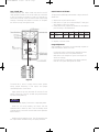
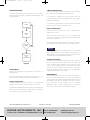
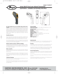
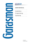
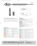
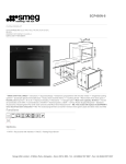
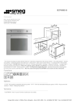
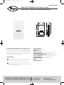
H-22-OSW:TEMPLATE
10/9/08
1:02 PM
Page 1
Bulletin H-22-OSW
Model OSW-100 Wall Mount Occupancy Sensor
Specifications - Installation and Operating Instructions
2-39/64
[66.28]
1-25/32
[45.24]
4-27/64
[112.32]
The Model OSW-100 Wall Mount Occupancy Sensor is
an infrared sensor designed to automatically control a
HVAC ventilation system. A unique dual delay processor
eliminates false triggers due to short-term occupancies. The
Model OSW-100 has a wide 110° viewing angle to capture
movement up to 49.2 ft (15 m) away.
INSTALLATION
Do not install where the detector is exposed to direct
sunlight or directly above strong sources of heat.
SPECIFICATIONS
Infrared Sensor: Dual Element.
Range: 49.2 ft (15 m).
Detectable Speed: 0.33 to 9.8 ft/sec (0.1 to 3.0 m/sec).
Control Output Rating: SPDT, 0.2A @ 30 VDC.
Ambient Operating Temperature: -4 to 140°F (-20 to 60°C).
Power Consumption: Standby: 5 mA, Operating: 18 mA.
Mounting Height: 5.9 to 11.8 ft (1.8 to 3.6 m).
Power Requirements: 22 to 26 VAC/DC.
Weight: 3.2 oz (90.7 g).
Agency Approvals: CE.
Do not install in areas that have any obstruction
(plants, large pieces of furniture, curtains, etc.) which
may block the detection.
DWYER INSTRUMENTS, INC.
P.O. BOX 373 • MICHIGAN CITY, INDIANA 46361, U.S.A.
Phone: 219/879-8000
Fax: 219/872-9057
www.dwyer-inst.com
e-mail: [email protected]
H-22-OSW:TEMPLATE
10/9/08
1:02 PM
Page 2
MOUNTING
CEILING MOUNT
The OSW-100 is designed to be mounted to a wall or
corner.
Step 1: Install Base Unit
• Determine the location of the sensor according to the
detection pattern shown in Figure 1.
• Screw the base of the mounting bracket to the desired
position on the wall as shown in Figure 2.
• Feed the cable through the hole on the back of the
bracket.
• Loosen the screw on the bottom of the sensor and
remove the cover.
• Feed the cable through the center hole on the back of
the sensor housing.
• Attach the sensor to the mounting bracket.
WALL MOUNT
1
3
2
Figure 2
Mounting the Sensor
Step 2: Wiring
• Turn the screw for each terminal counterclockwise.
• Connect the cable to the corresponding terminals as
shown in Figure 3.
FAN COIL CONTROLLER
ON/OFF INPUT
Figure 1
Determining the Location of the Sensor
24 VAC/DC
• NC-COM-NO:
Output for ON-OFF
control of fan coil
operation. Dry contact
signal.
• 24V: Power Supply
(non-polarity)
NC
COM
NO
24V
Figure 3
Wiring the Sensor
H-22-OSW:TEMPLATE
10/9/08
1:02 PM
Page 3
Step 3: Walk Test
Before beginning test, make certain that the On and Off
delay jumpers (located on the circuit board) are connected
in the “A” positions as shown in Figure 4. If they are not,
follow the procedure under the section titled On/Off Delay
Settings to rearrange the jumpers to location “A.” Replace
the sensor housing and tighten screw.
ON/OFF DELAY SETTINGS
To adjust the On/Off Delay time intervals or adjust sensor for
“Walk Test.”
1. Remove the cover from the sensor.
2. Refer back to Figure 4 to locate the ON/OFF Delay pins
and jumpers on the circuit board.
3. Gently remove the jumpers and reinsert into the desired
pins according to the table below.
D
E
F
A (Walk Test) B
C
ON 0 Sec.
10 Sec. 30 Sec. 1 Min. 5 Min. 10 Min.
OFF 10 Sec.
1 Min. 5 Min. 10 Min. 20 Min. 30 Min.
4. Replace cover and screw.
Range Adjustment
After installation, the sensor can be manually adjusted to
meet the detection needs of a room.
• Loosen the screw on the mounting bracket and then
carefully move the unit to the desired direction.
• Refer back to the diagram in Figure 1 and adjust the
sensor accordingly.
• Once the sensor is orientated in the desired direction,
hold the unit in place and tighten the screw.
Figure 4
The walk test is used to quickly ensure correct system
wiring, proper functioning of the output, and proper
orientation/location of the sensor.
• Apply power to the unit and allow 45 seconds for the
sensor to warm up. The LED will blink (long blink followed
by short) during warm up.
NOTICE
The LED will blink rapidly if the sensor is improperly wired.
• When the LED stops blinking, the sensor has had
adequate time to warm up and is now in standby mode
(Standby mode is discussed in more detail in the Operation
Mode Section.)
• Walk across the detection zone. The LED will stay lit and
the output will be activated during occupancy detection.
H-22-OSW:TEMPLATE
10/9/08
1:02 PM
Page 4
OPERATION MODES
The OSW-100 Wall Mount Occupancy Sensor utilizes
several operation modes to eliminate false readings and
conserve energy.
A.
If occupancy is detected at any point within that one
minute, the output device is activated and the sensor enters
Relay Off Delay Mode.
If occupancy is not detected in that one-minute time frame,
the sensor enters back into standby mode.
STANDBY
DETECTION
Relay Off Delay Mode
During this mode, the sensor’s output is activated for a
preset period of time.
B.
RELAY ON
DELAY
C. 1-MINUITE
WAITING
1-Minute Warning Mode
During this mode, the sensor searches for any movement
for one minute past the Relay On Delay Mode.
Once this preset time interval is up, the output device
powers off. However, the relay off delay timer will reset with
each motion detection.
This Relay Off Delay Mode allows for energy conservation
by eliminating unnecessary running of the HVAC system.
NO
DETECTION
NOTICE
Occupancy detection may be affected if the unit is operated
within radio frequency electromagnetic field strength of
approximately 3 volts per meter, but the performance of the
instrument will not be permanently affected.
DETECTION
D.
RELAY OFF
DELAY
(RELAY OUTPUT)
Figure 5
Standby Mode
Before any movement is being sensed, the sensor is in
standby mode.
When the sensor detects occupancy, the LED light turns on
and the sensor switches to Relay On Delay Mode.
Relay On Delay Mode
This adjustable mode allows the user to choose the time
delay before the unit reports that a space is occupied.
Storage and Cleaning
The sensor lens is the most delicate part of the Occupancy
Sensor. The lens should be kept clean at all times, care
should be taken when cleaning the lens using only a soft
cloth or cotton swab with water or medical alcohol. Allow
the lens to fully dry before using the sensor. The sensor
should be installed or stored in an area of room temperature
between -4 and 140ºF (-20 to 60ºC).
MAINTENANCE
After final installation of the unit, no routine maintenance is
required. The Model OSW-100 is not field serviceable and
should be returned if repair is needed (field repair should not
be attempted and may void warranty). Be sure to include a
brief description of the problem plus any relevant
application notes. Contact customer service to receive a
return goods authorization number before shipping.
The Relay On Delay Mode allows for energy conservation by
bypassing short-term or faulty occupancies. It is followed by
a secondary one minute warning delay.
©Copyright 2008 Dwyer Instruments, Inc.
Printed in U.S.A. 9/08
DWYER INSTRUMENTS, INC.
P.O. BOX 373 • MICHIGAN CITY, INDIANA 46361, U.S.A.
Phone: 219/879-8000
Fax: 219/872-9057
FR# R6-443398-00
www.dwyer-inst.com
e-mail: [email protected]