1
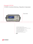
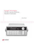
Agilent 33210A 10 MHz Function/Arbitrary
Waveform Generator
Data Sheet
• 10 MHz Sine and Square
waveforms
• Pulse, Ramp, Triangle, Noise,
and DC waveforms
• Optional 14-bit, 50 MSa/s,
8K point Arbitrary Waveform
Generator
• AM, FM, and PWM
modulation types
• Linear & logarithmic sweeps
and burst operation
• 10 mVpp to 10 Vpp amplitude
range
• Graph mode for visual
verification of signal settings
• Connect via USB, GPIB and
LAN
• Fully compliant to LXI
Class C specification
Uncompromising performance
at an affordable price
The Agilent Technologies
33210A Function/Arbitrary
Waveform Generator is the
latest addition to the 332XX
family. Waveforms are generated
using direct digital synthesis
(DDS) technology which creates
stable, accurate low distortion
sine waves as well as square
waves with fast rise and fall
times up to 10 MHz and linear
ramp waves up to 100 kHz.
For user defined waveforms,
Option 002 provides 14-bit,
50 MSa/s 8K point Arbitrary
Waveform Generation.
Pulse generation
The 33210A can generate
variable-edge-time pulses up
to 5 MHz. With variable period,
pulse width, and amplitude
the 33210A is ideally suited to
a wide variety of applications
requiring a flexible pulse signal.
Custom waveform generation
(Option 002)
The optional 8K point arbitrary
waveform generator (Option 002)
can be used in the 33210A to
generate complex custom waveforms. With 14-bit resolution,
and a sampling rate of 50 MSa/s,
the 33210A gives you the flexibility to create the waveforms
you need. It also lets you store
up to four waveforms in nonvolatile memory.
The Agilent IntuiLink Arbitrary
Waveform software allows you
to easily create, edit, and download complex waveforms using
the waveform editor. Or you
can capture a waveform using
IntuiLink for Oscilloscopes
and send it to the 33210A for
output. To find out more about
IntuiLink, visit
www.agilent.com/find/intuilink
Measurement Characteristics
Easy-to-use functionality
Front-panel operation of the
33210A is straight-forward and
user friendly. You can access all
major functions with a single
key or two. The knob or numeric
keypad can be used to adjust
frequency, amplitude, offset, and
other parameters. You can even
enter voltage values directly in
Vpp, Vrms, dBm, or as high and
low levels. Timing parameters
can be entered in Hertz (Hz)
or seconds.
Internal AM, FM, and PWM
modulation make it easy to
modulate waveforms without the
need for a separate modulation
source. Linear and logarithmic
sweeps are also built in, with
sweep rates selectable from 1 ms
to 500 s. Burst mode operation
allows for a user-selected number
of cycles per trigger. GPIB, LAN,
and USB interfaces are all standard, plus you get full programmability using SCPI commands.
External frequency reference
(Option 001)
The 33210A external frequency
reference lets you synchronize
to an external 10 MHz clock, to
another 33210A, or to an Agilent
33220A or Agilent 33250A. Phase
adjustments can be made from
the front panel or via a computer
interface, allowing precise phase
calibration and adjustment.
Waveforms
Standard
Sine, Square, Ramp,
Triangle, Pulse, Noise, DC
Built-in arbitrary wave- Exponential rise,
forms (available only Exponential fall, Negative
with Option 002 ARB) ramp, Sin(x)/x, Cardiac
Waveform Characteristics
Sine
Frequency range
1 mHz to 10 MHz
(relative to 1 kHz)
Amplitude
< 100 kHz
0.1 dB
Flatness [1], [2]
100 kHz to 5 MHz 0.2 dB
5 MHz to 10 MHz 0.3 dB
Harmonic distortion [2], [3]
< 1 Vpp
≥ 1 Vpp
DC to 20 kHz
-70 dBc
-70 dBc
20 kHz to 100 kHz -65 dBc
-60 dBc
100 kHz to 1 MHz -50 dBc
-45 dBc
1 MHz to 10 MHz
-40 dBc
-30 dBc
Total harmonic distortion [2],[3]
DC to 20 kHz
0.04%
Spurious (non-harmonic) [2],[4]
DC to 1 MHz
-70 dBc
1 MHz to 10 MHz
-70 dBc + 6 dB/octave
Phase noise
(10 kHz offset)
-115 dBc / Hz, typical
Square
Frequency range
1 mHz to 10 MHz
Rise/fall time
20 ns
Overshoot
< 2%
Variable duty cycle
20% to 80% (to 5 MHz)
40% to 60% (to 10 MHz)
Asymmetry
1% of period + 5 ns
(@ 50% duty)
Jitter (RMS)
1 ns + 100 ppm of period
Ramp, Triangle
Frequency range
1 mHz to 100 kHz
Linearity
< 0.1% of peak output
Variable symmetry
0.0% to 100.0%
Pulse
Frequency range
1 mHz to 5 MHz
Pulse width
40 ns minimum
(period ≤ 10 s)
10 ns resolution
Variable edge time
20 ns to 100 ns
Overshoot
< 2%
Jitter (RMS)
300 ps +
0.1 ppm of period
Noise
Bandwidth
7 MHz typical
8K-point Arbitrary Waveform Generator
(Option 002)
Frequency range
Waveform length
Amplitude resolution
Sample rate
Min. rise/fall time
Linearity
Settling time
1 mHz to 3 MHz
2 to 8 k points
14 bits (including sign)
50 MSa/s
70 ns typical
< 0.1% of peak output
< 500 ns to 0.5% of final
value
Jitter (RMS)
6 ns + 30 ppm
Non-volatile memory 4 waveforms
Common Characteristics
Frequency
Accuracy [5]
Resolution
Amplitude
Range
Accuracy [1],[2]
(at 1 kHz)
Units
Resolution
DC Offset
Range
(peak AC + DC)
Accuracy [1],[2]
Resolution
Main Output
Impedance
Isolation
Protection
10 mVpp to 10 Vpp into
50 Ω
20 mVpp to 20 Vpp into
open circuit
± 2% of setting
± 1 mVpp
Vpp, Vrms, dBm
3 digits
± 5 V into 50 Ω
± 10 V into open circuit
± 2% of offset setting
± 0.5% of amplitude
± 2 mV
3 digits
50 Ω typical
42 Vpk maximum to earth
Short-circuit protected,
overload automatically
disables main output
External Frequency Reference (Option 001)
Rear Panel Input
Lock range
Level
Impedance
Lock time
Rear Panel Output
Frequency
Level
Impedance
Phase Offset
Range
Resolution
Accuracy
2
± (10 ppm + 3 pHz)
in 90 days
± (20 ppm + 3 pHz)
in 1 year
1 µHz (internal)
1 mHz (user)
10 MHz ± 500 Hz
100 mVpp to 5 Vpp
1 kΩ, typical
< 2 seconds
10 MHz
632 mVpp
(0 dBm), typical
50 Ω, typical
AC coupled
+360° to -360°
0.001°
20 ns
Measurement Characteristics (Continued)
Modulation
Programming Times (typical)
AM
Carrier waveforms
Source
Internal modulation
Configuration times
Function change
Frequency change
Amplitude change
Select user arb
Arb download times
(Option 002)
Depth
FM
Carrier waveforms
Source
Internal modulation
Deviation
PWM
Carrier waveforms
Source
Internal modulation
Deviation
Sine, Square
Internal/External
Sine, Square, Ramp,
Triangle, Noise, Arb [7]
(2 mHz to 20 kHz)
0.0% to 120.0%
Sine, Square
Internal/External
Sine, Square, Ramp,
Triangle, Noise, Arb [7]
(2 mHz to 20 kHz)
DC to 5 MHz
Sweep
Sine, Square, Ramp
Linear or Logarithmic
Up or Down
1 ms to 500 s
Single, External or Internal
Falling edge of sync
signal (programmable
frequency)
Burst [6]
Waveforms
Type
Start/stop phase
Internal period
Gate source
Trigger source
Sine, Square, Ramp
Counted (1 to 50,000
cycles), Infinite, Gated
+360° to -360°
1 µs to 500 s
External trigger
Single, External or Internal
Trigger Characteristics
Trigger Input
Input level
Slope
Pulse width
Input impedance
Latency
Jitter (rms)
Trigger Output
Level
Pulse width
Output impedance
Maximum rate
Fanout
TTL compatible
Rising or Falling,
selectable
> 100 ns
> 10 kΩ, DC coupled
< 500 ns
6 ns (3.5 ns for pulse)
GPIB
120 ms
2 ms
30 ms
130 ms
USB
5 ms
8 ms
14 ms
GPIB
10 ms
20 ms
40 ms
LAN
9 ms
15 ms
27 ms
General
Power supply
Pulse
Internal/External
Sine, Square, Ramp,
Triangle, Noise, Arb [7]
(2 mHz to 20 kHz)
0% to 100% of pulse width
External Modulation Input
(for AM, FM, PWM)
Voltage range
± 5 V full scale
Input impedance
5 kΩ typical
Bandwidth
DC to 20 kHz
Waveforms
Type
Direction
Sweep time
Trigger source
Marker
2 k points
4 k points
8 k points
USB
LAN
120 ms 120 ms
2 ms
3 ms
30 ms 30 ms
130 ms 130 ms
Binary transfer
Power consumption
Operating
environment
Operating
temperature
Operating humidity
Cat II
100 – 240 V @
50/60 Hz (-5%, +10%)
100 – 120 V @ 400 Hz
(± 10%)
50 VA max
IEC 61010
Pollution Degree 2
Indoor Location
0°C to 55°C
5% to 80% RH,
non-condensing
Operating altitude
Up to 3000 meters
Storage temperature -30°C to 70°C
State storage
Power off state
memory
automatically saved,
Four user-configurable
stored states
Interface
LAN LXI-C Ethernet 10/100
USB 2.0, GPIB
Language
SCPI – 1993, IEEE-488.2
Dimensions (W x H x D)
Bench top
261.1 mm x 103.8 mm
x 303.2 mm
Rack mount
212.88 mm x 88.3 mm
x 272.3 mm
Weight
3.4 kg (7.5 lbs)
Safety designed to
UL-1244, CSA 1010
EN61010
EMC tested to
MIL-461C, EN55011,
EN50082-1
Vibration and shock MIL-T-28800, Type III,
Class 5
Acoustic noise
30 dBa
Warm-up time
1 hour
TTL compatible into
≥ 1 kΩ
> 400 ns
50 Ω typical
1 MHz
≤ 4 Agilent 33210As
(or equivalent)
3
Footnotes
[1] Add 1/10th of output amplitude and offset
spec per °C for operation outside the range
of 18°C to 28°C
[2] Autorange enabled
[3] DC offset set to 0 V
[4] Spurious output at low amplitude is -75 dBm
typical
[5] Add 1 ppm/°C average for operation outside
the range of 18°C to 28°C
[6] Sine and square waveforms above 3 MHz are
allowed only with an “infinite” burst count
[7] Only available if Option 002 is installed
Ordering Information
Agilent 33210A
10 MHz Function/Arbitrary
Waveform Generator
Accessories included
Operating manual, service manual, quick
reference guide, IntuiLink waveform editor
software, test data, USB cable, and power
cord (see language option).
Options
Opt. 001 External timebase reference
Opt. 002 8K-point Arbitrary Waveform
Generator
Opt. 0B0 Delete printed manual
Opt. 1CM Rackmount kit
(also sold as Agilent 34190A)
Opt. A6J ANSI Z540 calibration
Opt. AB0 Taiwan: Chinese manual
Opt. AB1 Korea: Korean manual
Opt. AB2 China: Chinese manual
Opt. ABA English: English manual
Opt. ABD Germany: German manual
Opt. ABF France: French manual
Opt. ABJ Japan: Japanese manual
Opt. PLG Continental European
power cord
Remove all doubt
Our repair and calibration services
will get your equipment back to you,
performing like new, when promised.
You will get full value out of your
Agilent equipment throughout its
lifetime. Your equipment will be serviced by Agilent-trained technicians
using the latest factory calibration
procedures, automated repair diagnostics and genuine parts. You will
always have the utmost confidence
in your measurements.
Agilent offers a wide range of additional expert test and measurement
services for your equipment, including initial start-up assistance onsite
education and training, as well as
design, system integration, and
project management.
For more information on repair and
calibration services, go to:
www.agilent.com/find/removealldoubt
Other Accessories
34131A
34161A
34190A
Carrying case
Accessory pouch
Rackmount kit
www.agilent.com
For more information on Agilent
Technologies’ products, applications or
services, please contact your local Agilent
office. The complete list is available at:
www.agilent.com/find/contactus
Americas
Canada
Latin America
United States
877 894 4414
305 269 7500
800 829 4444
Asia Pacific
Australia
China
Hong Kong
India
Japan
Korea
Malaysia
Singapore
Taiwan
Thailand
1 800 629 485
800 810 0189
800 938 693
1 800 112 929
81 426 56 7832
080 769 0800
1 800 888 848
1 800 375 8100
0800 047 866
1 800 226 008
Europe & Middle East
Austria
Belgium
Denmark
Finland
France
0820 87 44 11
32 (0) 2 404 93 40
45 70 13 15 15
358 (0) 10 855 2100
0825 010 700*
*0.125 €/minute
Agilent Email Updates
Germany
01805 24 6333*
*0.14 €/minute
www.agilent.com/find/emailupdates
Get the latest information on the products
and applications you select.
Agilent Direct
www.agilent.com/find/agilentdirect
Quickly choose and use your test
equipment solutions with confidence.
Ireland
1890 924 204
Israel
972 3 9288 504/544
Italy
39 02 92 60 8484
Netherlands
31 (0) 20 547 2111
Spain
34 (91) 631 3300
Sweden
0200-88 22 55
Switzerland
0800 80 53 53
United Kingdom
44 (0) 118 9276201
Other European Countries:
www.agilent.com/find/contactus
Revised: March 27, 2008
www.agilent.com/find/open
Agilent Open simplifies the process of
connecting and programming test systems
to help engineers design, validate and
manufacture electronic products. Agilent
offers open connectivity for a broad range
of system-ready instruments, open industry
software, PC-standard I/O and global
support, which are combined to more
easily integrate test system development.
Product specifications and descriptions
in this document subject to change
without notice.
© Agilent Technologies, Inc. 2006, 2008
Printed in USA, August 1, 2008
5989-8926EN