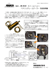
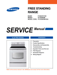
1
2008 Appliance Products 1 Chapter 1 Samsung Support Information 2 Support Contact Numbers • • • • • • • • Customer Service – 1-800-SAMSUNG (726-7864) Authorized Service Centers Tech Assist – 866-797-8736 (account number required) – Hours 9AM – 9PM Eastern Time – 11AM - 4PM Eastern Time Saturdays – Email [email protected] Non Authorized Service Centers – 201-584-0412- Fax service Only Warranty Assistance: 800-849-2198 option 8 Web Site Assistance: 1-201-229-4177 Web Site Assistance [email protected] Training Requests [email protected] Tech Talk Newsletter Subscriptions [email protected] • Global Service Partner Network http://service.samsungportal.com • Login and Password Issues: Elisa Pagliaro [email protected] • GSPN Content Issues: Jim Foster [email protected] Parts can be ordered through: Samsung GPCA Global Parts Center America Parts ordering or backorders 800-634-8276 or you may use: Marcone Appliance Parts 800-482-6022 3 Regional Service Managers Home Appliance Field Service 4 Be Prepared When Calling for Technical Assistance on Appliances Slow Times: 6-9 PM EST M-F; 11-4 EST Sat. For prescreening calls The technical assistance team needs four things when you call in, in this order: • Your account number • Product model number • Product serial number • Your name Please remember, Laundry and Refrigeration products have a letter at the end of the serial number. 5 Ref & Laundry Serial Number Information Model Name Production Line Check Digit 635543CP100160A Pro. Year Y : 2005 A : 2006 Jan L : From 2006 Feb P : 2007 Pro. Month 1~9 : Jan~Sep A : October B : November C : December Model Name 6 Refrigerator Model Number Nomenclature • RS = Side by Side • RF = French Door • RM = Four Door • RB = Bottom Mount Freezer 7 Technical assistance will not be able to help unless you are properly prepared with tools when you are with the product. • Multimeter requirements for appliance calls: – Accurately measure DC voltage to the hundredths of a volt (3.56vdc) from 1vdc to 24vdc with special meter leads or safety pins to read voltages at the small connectors on the main circuit board. – Accurately read resistance from 1 ohm to 200K ohms – Accurately read AC voltage from 16vac to 240vac – Replacement meter batteries!!!!!! • Please have an instrument available to accurately measure freezer and refrigerator temperatures. • An Amp Probe or Watt Meter would be an advantage. 8 Know your meter scales Use for Sensor Voltage Tests Or 20 VDC scale on some meters Use for Defrost Heater tests 9 REDO Prevention Tips Samsung Electronics is currently focusing on reducing our repeat repairs (Redo). We have prepared the following tips for all of our Service Centers to follow so that we can improve our overall service to our mutual customers. 1. The technician should always talk directly to the customer before each call. Many techs get their idea of what’s wrong via 2nd hand conversation, bring the wrong parts and put it in figuring doing something is better than nothing. This is a bad practice. 2. Ask the customer if there were any other symptoms before the current problem appeared. 3. If you do not see the defect during your visit and you are not sure what the problem is, do not guess on the repair. Confirm the symptom by picture, Technical support, or research on PVI website. 4. Do not submit a claim using EADJ if no adjustments were actually performed because this will contribute to a REDO if a 2nd call is needed. Be sure to properly code the repair. See list of repair codes on the next page which do not affect the REDO rate. 5. If you are 99% sure that one of two possible parts will repair the unit, change both parts. However, only do this when you are sure that this will repair the unit because one of our KPI is amount of parts used. 6. Spend time after the repair burning the part in (at least 20 min) and talk to the customer to make sure they are satisfied with the repair (not going to call back after you leave). 7. Please review your claim submission process to make sure that you are not submitting two claims for the same unit repair at the same time. These are some of the habits of the best technicians in the country. The best technicians also concentrate on having the correct parts in stock by reviewing their weekly usage. If you have any other tips which you have found to be successful in reducing repeat repairs, please send them to your RSM. 10 Repair Codes Excluded from REDO calculation: • • • • • • • • • • • • • CEST: Customer Refuse Estimate CLEA: Cleaning CLEN: Cleaning CUST: Customer Education DTYX: Dirty EXCP: EXCH-Company Policies EXES: EXCH-Excessive Service EXLW: EXCH-By law FACT: Factory Modification HOLD: Waiting for parts INST: Installation ISTL: Installation MACC: Missing Accessory Samsung will pay the minor warranty rate for a customer education call ONE time for each consumer product while under warranty • • • • • • • • • • • • • MISS: Missing MMCH: Mis-Match NPFD: No problem found NPRB: No problem found PANT: Paint RCON: Reconnect RECH: Recharge RECO: Reconnect RSTU: Reseat SCHX: Scratch SPEC: Specification measurement WSUP: Wrong Setup RCLL: Recall If a initial warranty claim is submitted with one of the above repair codes and another repair is submitted within 90 days the service center is NOT charged with a REDO 11 Quick Document Search 1. From the Main Menu Select “Warranty/Parts” 2. Type in the Model Number in the Left Hand Search Field HLP5063 3. Click on the Magnifier Button 4. Manuals and Bulletins are displayed with appropriate hyperlinks 12 Parts List Search To search for the Bill of Materials (BOM) 1. Click Warranty/Parts Tab 2. Order management -> Parts Information -> Parts list by Model 3. Type in the Model Code and click Search 13 Bill of Materials Search Tip 1. Click on the correct model code (Check country list on right to make sure it is the right model) 2. Check mark the parts you need and Click CREAT P/O or ADD TO CART 3. Service bulletins and tips can be found for the specific part 14 Chapter 2 Refrigerator Technology 15 Dual Evaporator with TDM valve The Time Divided Multi‐cycle (TDM) System (Stepper Valve) is used to switch refrigerant flow in the 4 Door (RM25*) and French Door (RFG29*) This improves temperature control and energy efficiency. Quad Cooling RM Model Twin Cooling RS/RF/RB Models 16 Inverter Compressor Inverter compressors offer energy savings not available in a standard compressor 17 Refrigerant Path Compressor Sub-condenser Hot Pipe Dryer Step valve R Capillary Tube R/CR Evaporator F Capillary Tube C/CF Evaporator Suction Pipe C Capillary Tube Compressor 18 Chapter 3 Refrigerator Troubleshooting 19 Refrigeration Troubleshooting • The Forced Operation Mode is a very valuable troubleshooting tool for testing compressor operation, fan operation and defrost operation. • Forced Freeze Mode • The compressor is started without the 5 minute delay • You can check the compressor voltage at the main PCB in this mode. • You can accurately check defrost sensor voltages in this mode • All fans will be turned on in this mode, to allow voltage testing. The door switches still control the fan operation. 20 Refrigeration Troubleshooting • Forced Freeze Mode Inverter Compressors • The compressor is started without the 5 minute delay • You can force the three speed options of this compressor • You can accurately check the temp and sensor operation • All fans will be turned on in this mode, to allow voltage testing. The door switches still control the fan operation. 21 Refrigeration Troubleshooting • Forced Defrost Operation • Standard compressor models can activate the Fridge defrost only, or both the Fridge and Freezer defrost. • Inverter compressor models activate all heaters at once. • In the Forced Defrost Mode the defrost sensor still controls the heater operation. When defrost is activated the main PCB will turn over defrost control to the sensor in about 90 seconds If the defrost sensor reads a temperature above the shut off point it will tell the main PCB to turn off the defrost voltage. • Even when the defrost is turned off the unit will stay in the forced mode for up to 24 hours. 22 Refrigeration Troubleshooting • Selecting the Forced Modes • When the two buttons are pressed together to enter the Forced Modes you must wait for the beep and the display to go blank. You then have 8 seconds to press the Freeze button to activate the Forced Freeze Mode. Once you are in this mode, press the Freeze button to advance to the next function. • Depending on the model, there are from two to four Forced Modes. You must always wait for the beeping to start before advancing to the next mode, if you wait over 8 seconds to press the Freeze button, you will have to start over again. If you lose track of where you are in the Forced Modes, unplug the unit and start over. 23 Forced Operation and Test Mode Test Mode Press both buttons simultaneously for 8 seconds! Display Code FF RD FD -- Function Forced Compressor Run Forced Refrigerator Defrost Forced Freezer Defrost Test Mode active Press any button one more time to cancellation Forced Mode Cancellation Forced Forced Operation Operation Press any button One time at the Test Mode Forced ForcedDefrost Defrost for forFridge Fridge Press any button One time at the Forced Operation Forced ForcedDefrost Defrost for forboth both compartment compartment Press any button one more time at the Forced Defrost for Fridge 24 Forced Operation For various refrigerator panels Press both buttons simultaneously for 8 seconds! Cancellation, unplug unit Press Freezer button One time at the Test Mode to Force Compressor Forced Forced Compressor Compressor Wait 5 seconds between button pushes Press Freezer button Second time for Forced Defrost of Fridge Forced ForcedDefrost Defrost for forFridge Fridge Press Freezer button a third time to Force Defrost for Fridge & Freezer Forced ForcedDefrost Defrost for forboth both compartment compartment 25 RFG29* Series Inverter Compressor Forced Mode For Test Mode Press both buttons simultaneously for 8 seconds! Press Freezer button One time at the Test Mode to Force each Compressor test Forced Forced Compressor Compressor High High Forced Forced Compressor Compressor Mid Mid 3600 RPM 2450 RPM Forced Forced Compressor Compressor Low Low Wait 5 seconds between button presses 2050 RPM Simultaneous manual defrost (fresh food and freezer compartments) function Press Freezer button a 4th time to Force Defrost for ALL Compartments Forced ForcedDefrost Defrost for for ALL ALL compartments compartments 26 RM257*** Series Inverter Compressor Forced Mode For Test Mode Press both buttons simultaneously for 8 seconds! Press Freezer button One time at the Test Mode to Force each Compressor test Forced Forced Compressor Compressor High High Forced Forced Compressor Compressor Low Low ~ 3600 RPM ~ 2450 RPM Forced Forced Compressor Compressor Mid Mid Wait 5 seconds between button presses ~ 2050 RPM Simultaneous manual defrost (all four compartments) function Press Freezer button a 4th time to Force Defrost for ALL Compartments Forced ForcedDefrost Defrost for for ALL ALL compartments compartments 27 Forced Mode for Single Evaporator units Use Freezer Key as a Test Key Wait 5 seconds between button pushes RS26/2530** 28 Refrigeration Troubleshooting • The Diagnostic Mode is the most valuable troubleshooting tool you have for troubleshooting a refrigerator. When you are at the product this is the first test you should do. • When a Samsung refrigerator is powered up if performs a Self Diagnosis, if an open or shorted sensor is detected it will lock the display and flash the code in the display. The refrigerator may have no operation, or operate in the emergency mode. Other faults detected will not lock the display or stop operation. • To restart operation put into Manual Diagnostic Mode. • Sensors that are off value, but not shorted or open, will not bring up a fault code. • Note: accessing this function resets ALL programming and error codes. 29 Refrigeration Troubleshooting • To enter the manual Diagnostic Mode you must press and hold two buttons, and hold them until the display stops blinking and beeps. • Fault code display for all models that have temperature numbers in the display: – Each 8 is made up of 7 segments, each of those segments is a possible fault code. • If there are no faults, the display will be blank or have all four (8888) showing. • On single evaporator units, no number display, lines or symbols will light up for faults. • On all models the display will come back to normal in about 12 seconds 30 Refrigeration Troubleshooting • A Sample fault code would be this is an example of an Ice Maker Sensor failure. • Things that can happen with this fault. • After a power failure the unit would be “dead”, lights work and blinking this code. • The Ice Maker is not making any ice • The Ice Maker is dumping partially frozen cubes • If you see the fault below, ignore it. This is a modem communication error not applicable in the US. 31 Self Diagnostics Press both buttons simultaneously for 8 seconds If a corresponding LED flickers, it means an abnormality of a sensor or component. 32 Self Diagnosis Hold Buttons until display stops blinking and beeps, then release and read fault codes. Various refrigerator panels shown 33 Error Code Display Pt 1 Error items for self-diagnostics Codes are shown for example, a full list of codes for the specific product is available in the service manual NO Error items 1 I/M-SENSOR 2 R-SENSOR LED TROUBLE Ice maker sensor measures open or shorted Refrigerator sensor measures open or shorted DEFROSTING 3 SENSOR OF R COMPARTMENT Refrigerator Defrost Sensor measures open or shorted 4 Refrigerator fan motor stuck or spinning to fast R-FAN ERROR Temperature Sensors are Negative Temp. coefficient measuring between 2.2 K and 100K ohms 34 Error Code Display Pt 2 Error items for self-diagnostics Codes are shown for example, a full list of codes for the specific product is available in the service manual NO 5 7 8 Error items LED TROUBLE I/M FUNCTION ERROR Ice maker did not return to level after an ice harvest, this is displayed after three attempts R-DEFROSTING ERROR Refrigerator Compartment defrosting heater- electric wire cut, short-circuit, contact failure, missing of sensor housing, or defective temperature fuse/bi-metal. The defect is also displayed if defrosting is not finished until after continuous heating over 80 minutes. CR-SENSOR CR Compartment Sensor Error- This can be an Electric wire cut, short-circuit, contact failure, or missing sensor. This can also be caused by a temperature reading > 122° or < -58 ° F. 35 Error Code Display Pt 3 Error items for self-diagnostics Codes are shown for example, a full list of codes for the specific product is available in the service manual NO Error items 9 DEFROSTING SENSOR OF CR COMPARTMENT CR compartment Defrost Sensor Error- This can be an Electric wire cut, short-circuit, contact failure, or missing sensor. This can also be caused by a temperature reading > 122° or < -58 ° F. 10 DEFROSTING SENSOR OF CF COMPARTMENT CF compartment Defrost Sensor Error- This can be an Electric wire cut, short-circuit, contact failure, or missing sensor. This can also be caused by a temperature reading > 122° or < -58 ° F. CR-DEFROSTING ERROR CR Compartment defrosting heater- electric wire cut, short-circuit, contact failure, missing of sensor housing, or defective temperature fuse/bi-metal. The defect is also displayed if defrosting is not finished until after continuous heating over 80 minutes. CF-DEFROSTING ERROR CR Compartment defrosting heater- electric wire cut, short-circuit, contact failure, missing of sensor housing, or defective temperature fuse/bi-metal. The defect is also displayed if defrosting is not finished until after continuous heating over 80 minutes. 11 12 LED TROUBLE 36 Error Code Display Pt 4 Error items for self-diagnostics Codes are shown for example, a full list of codes for the specific product is available in the service manual NO Error items 13 WATER HEATER ERROR 14 EXT-SENSOR 15 F-SENSOR 16 F-DEF-SENSOR LED TROUBLE Water Reservoir Heater measures open Ambient Temperature Sensor reads open or shorted Freezer Temperature Sensor reads open or shorted Freezer compartment Defrost Sensor Error- This can be an Electric wire cut, short-circuit, contact failure, or missing sensor. This can also be caused by a temperature reading > 122° or < -58 ° F. 37 Error Code Display Pt 5 Error items for self-diagnostics NO Codes are shown for example, a full list of codes for the specific product is available in the service manual Error items LED TROUBLE Freezer fan motor stuck or spinning to fast 17 F-FAN ERROR 18 C-FAN ERROR 19 CF-SENSOR CF Compartment Temperature Sensor reads open or shorted F-DEFROSTING ERROR Freezer Compartment defrosting heater- electric wire cut, shortcircuit, contact failure, missing of sensor housing, or defective temperature fuse/bi-metal. The defect is also displayed if defrosting is not finished until after continuous heating over 80 minutes. 20 Compressor fan motor stuck or spinning to fast 38 Error Code Display Pt 6 Error items for self-diagnostics Codes are shown for example, a full list of codes for the specific product is available in the service manual NO Error items 21 CF-FAN ERROR 22 CR-FAN ERROR 24 ICE PIPE HEATER ERROR LED TROUBLE CF Compartment fan motor stuck or spinning to fast CR Compartment fan motor stuck or spinning to fast Ice Maker Fill line heater measures open 39 Error Code Display Pt 7 Error items for self-diagnostics Codes are shown for example, a full list of codes for the specific product is available in the service manual NO Error items 25 Uart COMMUNICATION ERROR 26 27 L↔M COMMUNICATION ERROR P↔M COMMUNICATION ERROR LED TROUBLE This error is not applicable if you encounter this error during diagnostics ignore it Bad communication between LOAD↔MAIN MICOM Bad communication between LCD Panel ↔MAIN MICOM 40 2008 French Door Refrigerator Error Codes Codes are shown for example, a full list of codes for the specific product is available in the service manual 41 2008 French Door Refrigerator Error Codes Codes are shown for example, a full list of codes for the specific product is available in the service manual 42 Defrosting Troubleshooting Check for any fault codes in the manual Diagnostic Mode Frozen Evaporator YES Ask the Consumer if there has been water or ice build up on the bottom of the Fridge compartment or the floor. Check for frozen drain and/or open drain heater NO Frozen Evaporator YES Is the Defrost Heater Open? Replace heating element or evaporator NO Frozen Evaporator Is the Door gasket or door flap leaking? YES Replace door gaskets NO Frozen Evaporator Check for cracks in liner or air leaks 43 Testing Defrost Circuits Access the main PCB for voltage/resistance testing – – – – With the compressor running test the sensors Enter Forced Mode Defrost Measure the heater voltage Remove the power and heater connector and check the heater circuit resistance • Defrost Sensor – The sensor shuts off heater At 50℉ in Freezer, 63℉ in Fridge – If the sensor is bad it may shut off the defrost circuit in a few minutes or not start, causing ice build-up, or it could lock up in defrost mode and become a total no cool. Note: A defective sensor may check OK at room temperature, test at operating temperature only. 44 Defrosting Troubleshooting Part 1 • Defrost Sensors – Testing: Check the DC voltage across both evaporator defrost sensors, with the compressor running. They should read less than a tenth of a volt difference, as they are both on the same refrigerant line. They usually read ~ 3.7VDC, after the compressor has been running for about 10 minutes. You may find one reading about 30 to 50 degrees off (lower VDC - higher temp), if so replace it. • Alternate Sensor Testing Make ice slurry. To do this, fill a cup with ice (preferably crushed), then add water and a teaspoon of salt to make a slush. Mix thoroughly and allow to sit for 2 to 3 minutes. This will give you a 32℉ reference. Lower the sensor into the mixture and leave for about 1 minute, check the resistance. It should be very close to 13,300 Ω. Before reinstalling the sensor, be sure to rinse it with fresh water and dry it. 45 Defrosting Troubleshooting Part 2 Enter the Forced Mode per instructions • Check heater circuit amperage at the Main PCB or A/C line; look for ~1.2 amps for the Fridge and ~2.2 amps for the freezer or 3.4 amps total. NOTE: If compartment is warm, you only have about 90 seconds to test. • Freezer - Check service manual for connector and wire color code for the model being serviced. • Fridge - Check service manual for connector and wire color code for the model being serviced. • Low Current draw? Check individual defrost circuits, if one is low check for open defrost heater • No Current draw? Check voltages and resistances next. 46 Defrosting Troubleshooting Part 3 Enter the Forced Mode per instructions • Check the heater circuit voltage at the Main PCB; should be 120VAC for Freezer and Fridge. NOTE: If compartment is warm, you only have about 90 seconds to test. Listen for the relay closing then check the heaters. • Freezer Defrost Heater - Check service manual for connector and wire color code for the model being serviced. • Fridge Defrost Heater - Check service manual for connector and wire color code for the model being serviced. • No AC Voltage? Change Main PCB 47 Defrosting Troubleshooting Part 4 Heater circuit resistance - Unplug the refrigerator. Remove the defrost heater connector from PCB. • Freezer - Check heater circuit resistance at the Main PCB, look for 35–50 Ω average. • Fridge – Check heater circuit resistance at the Main PCB, look for 60-95 Ω average. • Freezer & Fridge - If resistance is around 2600 Ω, ThermoFuse (Bi-metal) is good, Defrost heater is open. • Open Circuit - Check the Thermal Fuse (Bi-metal), Heater and Connectors 48 Defrosting Troubleshooting Example of a 2600 Ω heater 49 Defrost Error Symptoms NOTE: Evaporator covers may break if removed while frozen as they are plastic, replace if damaged. • Ice build up in either the freezer or refrigerator compartment can be caused by a blocked drain. It is possible that the drain is not being defrosted by the heaters enough to properly clear the drain and pass the melted water into the catch pan. • Noise from the refrigerator/freezer fan or weak cooling. Noise disappears when the customer opens door. The defrost sensor, heater, thermal fuse/bimetal device are OK but ice is built up in the drain area of evaporator cover. 50 50 Defrosting Error Causes • The heat from the defrost heater does not transfer to the evaporator drain • The Styrofoam around the evaporator cover absorbs moisture and frost begins to form on the evaporator, defective evaporator cover. • During the defrost cycle, the frost melts and drips down to the drain where it becomes frozen again. • Ice blockage in the drain grows larger with every defrost cycle. • Because of the growing ice block, cooling efficiency diminishes at a growing rate and eventually blocks the fan blades. • Self diagnostics will eventually show a fan error. 51 Defrost Circuit Modification • Metal clips “A” and “C” can be placed on both the evaporator cover and the evaporator. The metal clips will touch and transfer heat more efficiently from the defrost heaters to the drain preventing ice build up. Part numbers for these parts are as follows: A: DA61-03502A PLATE-DRAIN INS EVAP, REF C: DA61-03585A FIXER-EVAP REF 52 Compressor Controller board connector arrangement and detail explanation (RM257AB*) Forced Modes: ① 12VDC ② 5VDC ③ Ground ④ Compressor RPM FF1 - Compressor high speed - 2.7 amps FF2 - Compressor low speed - 1.6 amps FF3 - Compressor medium speed - 2.0 amps FD - All defrost elements on - ~ 4.0 amps NOTE: FF2 & FF3 could be reversed. Compressor not running Check for 5 minute delay -- Not in delay Force Operation -- If no operation, disconnect CN03 (SMPS PCB) and check resistance to the windings. ~10 Ω Comp windings OK -- Disconnect CN02 (SMPS PCB), check resistance to overload Overload OK -- Replace Main PCB and Inverter PCB Compressor OLP 53 Model: RFG294 **, RFG295**, RFG299** Compressor Troubleshooting CN04 ① VDD ② VSS ③ RPM ④ FB CN01 POWER(115VAC) CN03 ① U ② V ③ W CN02 OLP Compressor not running Forced Modes: Check for 5 minute delay -- Not in delay FF1 - Compressor high speed - 2.7 amps Force Operation FF2 - Compressor medium speed - 2.0 amps If no operation, disconnect CN03 (SMPS PCB) and check FF3 - Compressor low speed - 1.6 amps resistance to the windings. ~ 10 Ω FD - All defrost elements on - ~ 3.4 amps Comp windings OK Disconnect CN02 (SMPS PCB), check resistance to overload Overload OK Replace Main PCB and SMPS PCB 54 Chapter 4 Common Refrigerator Service Issues 55 No Ice - Flex Tray I/M • • • • • For the ice maker to operate properly, water pressure between 20 and 125 PSI is required. A quick test of water pressure would be filling a 6 oz paper cup in less than 10 seconds. If the internal water filter is clogged, the water pressure to the icemaker will be reduced. The foreign matter at the water supply valve near the icemaker can also reduce the water pressure. Additionally, low water pressure at the fill tube can be c a u s e d b y a d e f e c t i v e f i l l t u b e h e a t e r . If the tray seems to be filling completely but the unit never harvests, verify the operation of the Icemaker sensor in the tray. Normally the unit harvests when the sensor reads approximately 1.5 degrees Fahrenheit for 5 minutes. The sensor should read about 3.7 volts at the main board connector when the cube temperature is 1.5 degrees. After the fill, the sensor will read water temp, 1.5 to 2.2 volts. Remember, using frame ground might produce inaccurate values; instead use the DC ground on the PC board. If this value is incorrect the sensor is suspected to be defective. You can also verify the operation of the harvest motor by pressing the black test unit on the motor housing near the back of the assembly. Is the freezer not dropping below 10 degrees? Make sure the Freezer defrost circuit is working properly and the evaporator and condenser fans are working correctly. Inspect condenser coil for air blockage. 56 Slow Ice - Flex Tray I/M • • • • This problem is usually caused by a defective sensor or low water pressure. The I/M sensor will delay the time by adding extra fills if the water pressure is low. Also check the operation of the freezer, if the freezer temperature is above 1.5 degrees, ice production will be delayed. This can also be caused by a problem with the freezer air vent, make sure the air duct near the ice maker is not restricted. If the unit is on an R/O water system, water pressure may be to low for consistent ice production. Is there any frost in the freezer compartment? Excessive frost could mean warm air leaking into the compartment warming the top of the freezer preventing the ice maker sensor from maintaining the necessary 1.5 degrees to harvest. • Check for ice chute failure, a leak at ice maker fill tube, an air leak around defrost water drain by evaporator coil, cracks in liner or a bad door seal. Finally make sure the most updated version of Ice maker kit has been installed. The ice maker designs in many models have been updated for better performance. Check GSPN for any related service bulletins regarding Ice-maker changes. 57 Shattered Ice Cubes - Flex Tray I/M • • • • • • When all ice shatters it's because of a bad tray or harvesting at a temp that is too cold (lower than 1.5 degrees), in some areas hard water issues that can also cause shattered cubes. The temp in the freezer should not have any effect on this issue, as long as it’s below 1.5 degrees, as a properly installed sensor will not read the freezer temp, only the water/ice temp. Check the Ice tray for defects in the plastic. Impurities or hard water can cause the plastic to become rough and inhibit the ice falling from the tray during the twisting. If this is the case, replace the tray assembly. It is possible to get ice too cold. Ice that is too cold will shatter during harvest. This can be from the (1) sensor not reading the correct temp (2) the sensor not mounted correctly (3) by programming the icemaker offset value to a lower number (4) the board not understanding the reading. To check the sensor you must check the tray temp (not air temp) and compare it to the sensor reading. The sensor should read about 3.7 volts at the main board connector when the cube temperature is 5 degrees. After the fill the sensor will read water temp 1.5 to 2.2 volts. To clear offsets, put unit into Diagnostics mode. Please note, some shattering is normal for a flex tray icemaker, especially if the Ice Off feature was used recently. 58 Service ConcernsHeat Release I/M • • • • Troubleshooting Observations Is there any frost in the freezer compartment? Excessive frost on the evaporator coil will either coat the coil enough to warm the air to 32 degrees to supply the ice room or block the air duct completely to the ice room. Make sure the Freezer defrost circuit is working properly and the freezer and ice room compartments are sealed properly The consumer complaint could be “it only makes ice once or twice a day” The Ice maker will harvest within a few hours of the freezer defrost cycle, when the evaporator is frost free. As the frost builds up on the evaporator again the ice maker will stop as the temperature is too warm. Ice making will stop until the next defrost cycle completes which will be 12 to 23 hours later. This is a defrost error not an icemaker error. Check the freezer door seal, ice room door seal and the freezer defrost heater. 59 Service Concerns – Heat Release I/M • Is the Ice Bucket locked firmly in position? • Try to move the bucket, when locked in place, any movement would mean that one of the locks is not latched. This will cause warm fridge air to enter the ice room and stop ice production. • Temperature checks (Actual) • The Back of Ice Room should measure 0 to 6 ℉ when making ice • The Back of Freezer compartment should measure -4 to +3 ℉ 60 Heat Release Ice maker - Troubleshooting • Voltage tests • The Ice Room Sensor voltage should match the actual ice room temperature; refer to the sensor voltage/ temperature chart in the service manual. • The Freezer Sensor voltage should match freezer temp and also be close to the actual ice room temperature, refer to the sensor voltage/ temperature chart in the service manual. If the bucket is full the Ice Room temperature should be around 24 ℉. 61 Heat Release Ice Maker - Troubleshooting • The Freezer Defrost Sensor Voltage should be 0 to -17 ℉, with the compressor running, to show no frost/ice buildup and good operating system, refer to the sensor voltage/temperature chart in the service manual. • The Ejecting Thermistor should not measure below 17 ℉, unless the bucket is full, as it should harvest at 18 ℉. If Ejecting Thermistor measures actual ice room temperature, and the bucket is not full, it would mean that the I/M is not harvesting. If there has been a recent harvest, the thermistor might measure up to 50 ℉ as the mold heater and fresh water has warmed the sensor. 62 Heat Release Ice Maker - Troubleshooting • If any of the sensors measure incorrectly replace the defective sensor • The Ice Room Fan should read around 7 to 9 VDC when it is running. Be sure to defeat the door open switch when testing the fans. You can force the fan to turn on by putting unit in Forced Freeze mode. • If the I/M Thermistor reads below 18 ℉ after 38 minutes and there is no harvest replace the main PCB 63 RF267**, RF26VAB** Not all Connectors and pins used on all models CN73 A/C Load 1-(CN70-1) Cube Solenoid (Yel-Red) RF267 3-(CN70-1) Auger Motor (Pnk-Red) RF267 5-(CN70-1) Dispenser Valve (W/Blk-Red) RF267,266 7-(CN70-1) Ice Maker Valve (Prp-Red) 9-(CN70-1) Ice Cover Route (Brn-Red) RF267 CN71 1-(CN70-1) R Lamps (Blu-Red) 3-(CN70-1) F Lamp (Prp-Red) 5 Common N (Gry) 7-(CN70-1) Comp (S/Blu-Red) 9 Heater Common (Org) CN72 (RF267 only) 1-(CN70-1)Ice Maker Motor (Brn) 3-(CN70-1)Ice Maker Heater (Wht) CN70 1 Common Line L (Red) 3-(CN71-5) Disp Heater (Blk-Gry) (RF267) 5-(CN71-5) French Heater (Yel-Gry) 7-(CN71-9) R Defrost (Wht-Org) 9-(CN71-9) F Defrost (Brn-Org) CN91 Pantry Room Damper 1-2 Damper Heater 12VDC (Blk-Brn) 3-4 Damper Motor (Wht-Blu) 5-6 Damper Motor (Yel-Red) CN10 Low Volt Pwr 1-3 5VDC (Red-Blk) 5-3 12 VDC (Yel-Blk) CN90 Ice Maker (RF267 only) 4-8 Eject Sensor (Wht-S/Blu) 5-8 Test Sw 5VDC (Gry-S/Blu) 6 Full Sw (Blu) 7 Horiz Sw (Prp) 8 Ground (S/Blu) CN78 4-5 Water Tank Htr (Brn-Blk) RF267 6,7,8 Pantry Disp 9-11 +12vdc (Blu-Wht) 10-11 +5vdc Sw input (Prp-Wht) CN50 Display 4-6 +12 VDC (Org-Pnk) 5-6 +5 VDC (Yel-Pnk) 8-(CN75-1) Water Sw (Blu-Red) RF266 CN30 Sensors & Switches 1-5 Freezer Dr Sw (Blk-Gry) 2-(CN50-7) R Door Sw (Prp-Gry) 3- (CN75-1) F Sensor (Red-Gry) 4-(CN75-1) F Def Sensor (Org-Gry) 6-(CN75-1) R Sensor (Wht-Gry) 7-(CN75-1) R Def Sensor (S/Blu-Gry) 8-9 Pantry Sensor (W/Blk- Gry) CN75 F, R, C Fans 2-1 F Fan (Yel-Gry) 3-1 R Fan (Org-Gry) 4-1 C Fan (S/Blu-Gry) 5 F Fan FG (Blk) 6 R Fan FG(Brn) 7 C Fan FG(Red) CN32 Sensor 1-4 Ambient Sensor (Wht-Wht) 2-(CN75-1) 5VDC to I/M (Red-Gry) RF267 3-(CN75-1) Ice Room Sensor (Org-Gry) RF267 CN76 Ice Room (RF267 only) 1-(CN75-1) Ice Room Fan (Blk-Gry) 2 Ice Fan FG (Brn) 3-(CN75-1) Ice Bucket Sw (Red-Gry) 64 Model : RFG 294 **, RFG295**, RFG299** Not all Connectors and pins used on all models CN74 A/C Load 1-(CN70-9) Cube Solenoid (Yel-Red) 3-(CN70-9) Auger Motor (Pnk-Red) 5-(CN70-9) Dispenser Valve (W/Blk-Red) 7-(CN70-9) Ice Maker Valve (Prp-Red) 9-(CN70-9) Ice Cover Route (Blu-Red) CN71 1-(CN70-9) R Lamps (Blu-Red) 3-(CN70-9) F Lamp (Prp-Red) 9 Heater Common (Org) CN73 1-(CN70-9) I/M Heater (Brn-Red) 3-(CN70-9) I/M Motor (Wht-Red) CN76 F, R, C Fans 2‐1 Ice Room Fan (Blk‐Gry) 3‐1 F Fan (Yel‐Gry) 4‐1 R Fan (Org‐Gry) 5 C Fan (S/Blu‐Gry) 6 Ice Room Fan FG(Pnk) 7 F Fan FG(Brn) 8 R Fan FG(Red) 9 C Fan FG(Blu) CN31 Sensor 1‐4 Ambient Sensor (Wht‐Wht) 2‐(CN90‐8) 5VDC to I/M (Red‐S/Blu) 3‐(CN76‐1) Ice Room Sensor (Org‐Gry) CN78 Lamp/Veg LED 4-7 +13vdc (Red-Gry) CN77 Stepper Motor 1 +13 vdc (Red) CN30 Sensors & Switches 1‐5 Freezer Dr Sw (Blk‐Gry) 2‐(CN50‐7) R Door Sw (Prp‐Gry) 3‐ (CN76‐1) F Sensor (Red‐Gry) 4‐(CN76‐1) F Def Sensor (Org‐Gry) 6‐(CN76‐1) R Sensor (Wht‐Gry) 8‐(CN76‐1) R Def Sensor (S/Blu‐Gry) 9‐ (CN76‐1) Pantry Sensor (W/Blk‐Gry) CN91 Pantry Room Damper 1‐2 Damper Heater 12VDC (Blk‐Brn) 3‐4 Damper Motor (Wht‐Blu) 5‐6 Damper Motor (Yel‐Red) CN90 Ice Maker 4-8 Eject Sensor (Wht-S/Blu) 5-8 Test Sw 5VDC (Gry-S/Blu) 6 Full Sw (Blu) 7 Horiz Sw (Prp) 8 Ground (S/Blu) CN70 1-11 Disp Heater (Blk-Gry) 3-11 French Heater (Yel-Gry) 5- (CN71-9) R Defrost (Wht-Org) 7- (CN71-9) F Defrost (Brn-Org) 9- L1 (Red) 10- N (Gry) CN50 Display 4‐6 +13 VDC (Org‐Pnk) 5‐6 +5 VDC (Yel‐Pnk) 8‐6 Ice/Water Sw (Blu‐Pnk) 9‐6 Ice Rte Sw 1(Prp‐Gry) 10‐6 Ice Rte Sw 2 (Wht‐Gry) CN51 Pantry Room 7‐5 +13vdc (Blu‐Wht) CN75 To Comp Inverter Board CN79 1‐2 Photosynthesis Module (Blk‐Brn) 10‐6 Water Tank Htr (Wht‐Pnk) 65 Common Defrost Problems Evaporator frozen, solid ice • Fridge – Bad evaporator cover, open drain heater, add Fixer and Plate, or blocked drain. • Freezer – Open drain heater, bad evaporator cover, add fixer and plate, or blocked drain Evaporator frozen, all frost • Fridge or Freezer – Bad defrost sensor, open thermal fuse, bad main PCB, open defrost heater • Ice Chute Flapper not Sealing properly 66 Defrost Service Single Evaporator Models • Frost/Ice forming on the evaporator cover and blocking fan and air tunnel to fridge. – Install Repair Kit for Serial Number range: up to **42BL3***** Units manufactured before April of 2006 For model RS2630 – Check for ice chute failure, leak at ice maker fill tube, air leak around defrost water drain by evaporator coil, cracks in liner, or door seal on fridge or freezer. – Excessive door openings, doors left open for long periods, hot foods put in fridge Evaporator frozen, solid ice • Blocked drain Evaporator frozen, all frost • Bad defrost sensor, open thermal fuse, bad main PCB, open defrost heater 67 No Cool Service Issues Both Compartments • • • • Unit locked in defrost mode Compressor relay failure on main PCB Failure of both defrost circuits No sealed system charge Fridge • • • Failure of defrost circuit Evaporator fan failure Door switch failure Freezer • • • • Failure of defrost circuit Evaporator fan failure Door switch failure Low sealed system charge 68 Service Access • Disassembly of Quattro Cool Evaporator Covers, both access the same way 69 Chapter 5 Refrigerator Installation For additional installation details see the accompanying 2008 Installation DVD 70 Water Connection 1 2 - Insert the plastic water pipe hose to the existing water source and fix it with compression hardware. If there is no existing icemaker water line consult a licensed plumber. Connect Water Pipe Hose - Check if there is any water leakage at the connection areas and if the hose is being kinked. When there is water leaking, try connecting again. Secure the Water Pipe Tube Dress the Water Pipe Tube - With a C/F clip, fix the water pipe hose to the refrigerator wall. Make sure that the water pipe hose is not kinked or damaged when dressing the excess water pipe. Example of Bad Installation Coiled hose, no backup tube, water hose touching the floor. Example of Good Installation No coiled hose, backup tube added, water hose does not touch on the floor. 71 Refrigerator Filter Housing Damage Always use the original Samsung filter when replacement is required at the six month interval. When aftermarket filters are used, there is the possibility that the filter will leak causing the water to freeze if the refrigerator temperature is set too low. When the water freezes there is the possibility that the filter housing will crack and start flowing water into the refrigerator compartment. When this happens the housing must be replaced. Coat the “O” rings here here Housing may crack and leak In order to put the filter in smoothly and to be able to remove it without forcing it, try coating the “O” rings with medical grade silicone. Note: Replacement refrigerator water filters will no longer be considered a service item and will exclusively be handled by Samsung sales and marketing groups. 72 Door Removal – French Door Model 1. With the door opened, remove the Top Table cap ① with a Flat head screwdriver, and close the door. Remove the 3 screws holding down the Top Table and remove the Top Table ②. Refrigerator Door 㣞 㣝 㣠 2. Disconnect the electrical connector ③ above the upper right door hinge and the 3 electrical connectors ④ above the upper left door hinge. Disconnect the water tube ⑤ by pulling the tube fitting ⑥ apart as shown in the picture. 㣟 㣢 㣡 73 Door Removal – French Door Model 3. Remove the 3 hex head bolts ⑦ found attached to the upper left and right door hinges with a Wrench (10mm). With a Philips head screwdriver, remove the ground screw ⑧ found attached to the upper left and right door hinges. Remove the upper left and right door hinges ⑨. Refrigerator Door 㣣 㣥 㣤 4. Lift the door straight up to remove. 5. With a Philips head screwdriver, remove the 2 screws ⑩ attached to the lower left and right door hinges. With a Wrench (10mm), remove the 2 hex head bolts ⑪ attached to the lower left and right door hinges. Remove the lower left and right door hinge ⑫. 㣦 㣧 㣨 74 Door Removal – French Door Model 1. Pull the drawer open to full extension 2. Remove the tilting pocket ① by pulling the both brackets ② upward at the same time. Freezer Door 㣝 㣞 3. Take out the lower basket ③ by lifting the basket up from rail system 4. Remove a fixing pin ④ and remove a shaft ⑤ by pushing it to the right side with your hand. 5. Separate the rail from the rail cover by pushing the hooks ⑥ in on both sides of the rail. After pushing the hooks in, remove the drawer by pulling towards you with both hands. 㣟 㣡 㣠 㣢 75 Door Removal – Side by Side Model 䱰 䱯 䱖 䱯 䱯 䱕 䱯 Take off the Leg-Cover by Removing the 3 screws. 䱰 Separate the Water Line by pressing the coupler 䱕 and pulling the water tube 䱖 away. 䱯 With the Door closed, remove the screw on the Upper Hinge Cover. 䱰 Disconnect the wires by gently pulling the connectors apart. 䱰 䱯 If necessary, remove the Reed S/W using a flat blade screwdriver. 䱰 Remove the Earth screw and the 3 bolts as shown. 䱯 䱰 䱯 Remove the Upper Hinge and remove the wiring harness from the hinge slot. 䱰 Remove the door from the lower hinge by lifting up the door straight. 76 Door Removal – Bottom Mount Model Hinge Cover 1. After removing the screw, disassemble the Upper Right Hinge Cover with opening door. Refrigerator Door 2. Disconnect electric wire on the top of the refrigerator. 3. With the 7/16 inch wrench, remove the three bolts that hold the top of the refrigerator. 77 Door Removal – Bottom Mount Model 4. Remove the screw that hold the ground wire. Refrigerator Door 5. Separate Hinge from electric wire and ground wire as shown below. 6. Disassemble the fridge door by lifting it upward. Be careful not to drop and scratch the fridge door. 78 Door Removal – Bottom Mount Model Refrigerator Door 7. Separate the Cap assembled on the Middle Hinge. Middle Hinge Freezer Door 1. After removing the screw and two bolts, disassemble Middle Hinge. 79 Door Removal – Bottom Mount Model 2. Remove/Disassemble the Middle Hinge connected to the Freezer. Freezer Door 3. Disassemble the Freezer door by lifting it upward. Be careful not to drop and scratch the Freezer door 4. Disassemble the Cap on the Low Hinge. 80 Chapter 6 Best Refrigerator Repair Practices 81 Refrigerator Truck Stock Recommendations Part 1 • The recommended truck stock items list updated bi- monthly please check the TechTalk Newsletter for the most updated listing ( ) = Stock Quantity (4) DA47-10160H Bi-Metal to replace all Thermal Fuses (1) DA67-00466B Water Filter Bypass Cap (used to verify filter operation) (1) DA62-00914B Water Valve (2) DA73-30102E Drier (2) DA73-30102F Drier (1) DA31-00010C (DA31-00015A, DA31-00015B, DA31-00015C, DA31-00010D, DA31-00010F) Condenser Fan Blade (1) MK183CL2U/E01 (MK183CL2U/E07) Compressor Defrost Sensor Common Part Number (4) DA32-00006W -- Defrost Sensor with longest wires Note: Replacement refrigerator water filters will no longer be considered a service item and will exclusively be handled by Samsung sales and marketing groups. 82 Refrigerator Truck Stock Recommendations Part 2 • The recommended truck stock items list updated bi- monthly please check the TechTalk Newsletter for the most updated listing ( ) = Stock Quantity Motors (1) DA31-00020E DC Evaporator Fan Motor (1) DA31-00002V A/C Evaporator Fan Motor (1) DA31-00020H DC Condenser Fan Motor (1) DA31-00103A Condenser Fan Motor Ice Makers with sensor (1) DA97-00258E Description: ASSY ICE MAKER (1) DA97-00258C Description: ASSY ICE MAKER (1) DA59-00294A Description: ASSY ICE MAKER (1) DA97-00258J Description: ASSY ICE MAKER (1) DA97-05422A Description: ASSY ICE MAKER All Heat Release 83 Chapter 7 Window Air Conditioner 84 Window Air Conditioner Error Code ERROR Room Temperature Sensor (open or short) 7 Segment LED Display E1 is displayed 85 Air Conditioner Troubleshooting Pt 1 Check the basic checkpoints first to determine whether it is machine trouble or a problem in the operation method. When it is not related to the basic checkpoints, perform checking in accordance with the procedures of troubleshooting by symptom. 7-1 Basic Checkpoints for Troubleshooting 1) Is the voltage of the power source appropriate ? ¾It should be within the rating voltage ±10% range. ¾The air conditioner may not operate properly when the voltage is out of this range. 2) Is the connection with the fan motor, compressor wire, and starting condenser appropriately made ? 3) The symptoms listed in the table below are not indicative of machine trouble. 86 Troubleshooting 87 Troubleshooting No Power (1) Is the voltage of the power source normal? (the rating voltage ±10% range.) (2) Are the electric wires making good contact? (CN 71, RY 71) (3) Is the output voltage of regulator IC01 (KA 7812) normal? (DC 11.5V ~ DC 12.5V) (4) Is the output voltage of the regulator IC02 (KA 7805) normal? (DC 4.5V ~ DC 5.5V) 88 Troubleshooting The Membrane Key Pad And Led Display are not working (1) Is the voltage of the power source normal? (the rated voltage ±10% range.) (2) Are the electric wires making good contact? (CN71, RY71) (3) Is the connection between the main PCB assembly, and MEMBRANE KEY PAD making good contact? (CN91) 89 Troubleshooting The Remote Control Is Not Working (1) Is the voltage of the power source normal? (the rated voltage ±10% range. ) (2) Are the electric wire making good contact? (CN71, RY71) (3) Is the main PCB assembly making good contact with the MEMBRANE KEY PAD (CN91) (4) Is the battery voltage of the remote control above 2.7VDC? 90 Troubleshooting The Compressor is Not Operating (1) Is the voltage of the power source normal? (the rated voltage ±10% range) (2) Is the desired temperature lower than the indoor temperature in the “COOL” mode? (Compressor stopped) (3) Are the starting condenser connectors making good contact? (4) Are the electric wires in good condition and making contact? (CN71, RY71) (5) Is the output voltage of the regulator IC01 (KA7812) 12VDC and IC02 (KA7805) 5VDC normal ? 91 Troubleshooting The Fan Motor does not Operate (1) Is the voltage of the power source normal? (the rated voltage ±10% range. ) (2) Are the electric wire making good contact? (CN71, RY71) (3) Are the starting condenser (FAN MOTOR) wires making good contact? (4) Is the fan motor connector making good contact? (CN73) (5) Is the output voltage of the regulators IC01 (KA7812) and IC02 (KA7805) normal? 92 Checking Compressor Oil To check the condition of the oil, fill a transparent container with a 10cc sample of oil, and then compare color and odor to the chart. Oil Quality Replacing and refilling the refrigerant oil 93 Chapter 8 Dishwasher 94 2008 Dishwasher DMR57 DMR77 Product Overview This DMR57 and DMR77 offers unique features and user flexibility. The sleek design creates a custom built kitchen look. The safety features and quiet design will provide reliable operation. 96 Product Specifications Model name DMR 77LFS DMR 57LFS Power Supply Single phase AC 110V / 60Hz Water Pressure 20 ~ 120 PSI. Wash spray method Rotating nozzle spray type Drying method Fan driven condensing system Power consumption Standard cycle: 1.03 KWh ± 10% Power Circulation Motor: 170W±15% or below Heater: 1100W±10% or below Drain Pump: 45W±15% or below Fan Motor: 5.5W±15% or below Water consumption 5.2 Gallons ± 15% or below Main Features Capacity: 14 place settings Control panel design - Touch Sensor panel & LED Display - DMR77 : Hidden type - DMR57 : Front type Dimension (W x D x H) : 23.8 x 24.7 x 33.9 inch 97 Product Comparison Specification DMR77LHS DMR57LFS Capacity 14 place settings 14 place settings Display Graphic LED Graphic LED Control Type Touch Sensor Touch Sensor Control height 5.1 inches 5.1 Inches Front Display PC 3.5t - Washing Program Normal, Heavy, Delicate, Rinse, Quick, Smart Auto Normal, Heavy, Delicate, Rinse Delay Start, Sanitize, Half Load Delay Start, Sanitize Water Supply Hot water only Hot Water Only Basket Color Gray Color (Nylon Coating) Gray Color (Nylon Coating) Basket Stair Style Basket Stair Style Basket Sensor Inlet/Temp/Water Level/Rinse/Leakage Inlet/Temp/Water Level/Rinse/Leakage Rinse Supplement Direction Yes Yes Half Load capable Yes (Upper) No Filter 3-stage (Disposer Type) 3-stage (Disposer Type) Heater Internal Type (1100W) Internal Type (1100W) Dryer Type Fan driven condensing system Fan driven condensing system Program Lock Child Lock Button Child Lock Button Delay Start 1~ 24hr 1~24hr SIZE 23.8×24.7×33.9 inch (W×H×D) 23.8×24.7×33.9 inch (W×H×D) 98 Model Number Nomenclature 99 Water Flow Path 100 Water Flow Samsung uses 3 wash arms, top (1), middle (2), and bottom (3). 1 The main water spraying arm in the middle is tilted. Its tilted shape sprays the water effectively in all parts of the machine. This is important for washing 14” Plates 2 Conventional washers use a spray wash pattern that sometimes may not reach all of the dish racks equally. The unique spray arm style distributes water to the entire drum promoting even cleaning. 3 101 Operating Principles Inner Space cycle Pre wash Dishes Main wash Front Dishes Rinse Dry Water Heater D i s p o s e r Grinds the leftover food to make the particles smaller in size High temperature water 102 Fan Driven Condensation Drying Samsung’s drying system is the fan-driven condensation type, which protects your kitchen and children, creating no steam from the machine when drying compared with vent drying system. This also speeds dish drying time. Samsung’s drying system is the fan-driven condensation type, it uses residual heat from the warm water inside the tub and the fan at the same time for efficient drying. 103 Delay Start / Sanitize Operation Delay Start Operation 䧒 Maximum Delay Time 24 Hours 䧒 Each button press postpones the start by 1 hour 䧒 Press Power to cancel Sanitize Operation 䧒 Enables High temperature cycle 䧒 At 3th Rinse step, the water temperature is increased to a maximum temperature of 162䨉. When [Sanitize] is not selected, the maximum temperature reaches 140 䨉 䧒 When [Rinse] Cycle is selected, you cannot select the [Sanitize] button. 䧒 When the [Sanitize] button is selected, the Cycle time can be extended. 104 Unique Functions Half Load 䧒 Selecting this option runs the upper spray arm only, Select this option to wash a small load of dishes. Child Lock ● [Child Lock] is selected by pressing the [Rinse] Button and [Quick] Button simultaneously for 3 seconds. You must press for 3 seconds again to cancel the selection. 105 Cycle Explanation 1 Normal Use this cycle for regular dinner dishes. 2 Heavy Use this cycle for hard-to-clean, heavily soiled dishes, pots, pans, and dishes with heavy oil. 3 Delicate 4 Rinse 5 Quick (only DMR77) Use this cycle for lightly soiled dishes. Detergent is dispensed but no dry cycle is initiated. 6 Smart Auto (only DMR77) This cycle detects the level of soil and automatically initiates the optimal cycle after a few minutes of operation. Use this cycle for normally soiled dishes or fragile items such as glasses. Use this cycle for pre-cleaned dishes or glasses. No detergent is dispensed and no dry cycle is initiated. 106 Cycle Selection Time Chart Program Drain Prewash 1 Prewash 2 Prewash 3 Main wash Rinse 1 Rinse 2 Last Rinse Dry Total Time Normal 0:45 16:30 (16:30) - 32:30 7:30 (7:30) 32:30 20 110~134 Heavy 0:45 17:30 17:30 17:30 46:30 7:30 7:30 46:30 20 181 Delicate 0:45 16:30 - - 37:30 7:30 - 32:30 20 115 Rinse 0:45 - - - - 9:30 - - - 11 Quick 0:45 5:30 - - 11:30 7:30 - 12:30 - 38 Smart Auto 0:45 5:30 ~17:30 (17:30) (17:30) 11:30 ~46:30 7:30 (7:30) 12:30 ~46:30 20 58~181 Program Pre-wash 1,2,3 Main wash Rinse 1,2 Normal - 120˚F Heavy - Delicate Rinse 3 No Sanitize Sanitize - 140˚F 162˚F 149˚F - 158˚F 162˚F - 113˚F - 140˚F 162˚F Rinse - - - - - Quick - 113 ˚F - 140˚F 162˚F Smart Auto - 113~149˚F - 140~158˚F 162˚F •The wash time may vary depending on the water pressure, drain conditions, and temperature of the supplied water. The Auto Wash cycle is not timed. 107 Cycle Time Chart MICOM cycle Program chart [ time (min), temperature ] Program Drain Prewash 1 Prewash 2 Prewash 3 Main wash Rinse 1 Rinse 2 Rinse 3 Dry Total Time Normal 0:45 16:30 (16:30) - 32:30 7:30 (7:30) 32:30 20 110~134 Heavy 0:45 17:30 17:30 17:30 46:30 7:30 7:30 46:30 20 181 Delicate 0:45 16:30 - - 37:30 7:30 - 32:30 20 115 Rinse 0:45 - - - - 9:30 - - - 11 Quick 0:45 5:30 - - 11:30 7:30 - 12:30 - 38 Smart Auto 0:45 5:30 ~17:30 (17:30) (17:30) 11:30 ~46:30 7:30 (7:30) 12:30 ~46:30 20 58~181 Program Pre-wash 1,2,3 Main wash Rinse 1,2 Normal - 120˚F (49˚C) Heavy - Delicate Rinse 3 No Sanitize Sanitize - 140˚F (60˚C) 162˚F (72˚C) 149˚F (65˚C) - 158˚F (70˚C) 162˚F (72˚C) - 113˚F (45˚C) - 140˚F (60˚C) 162˚F (72˚C) Rinse - - - - - Quick - 113 ˚F (45˚C) - 140˚F (60˚C) 162˚F (72˚C) Smart Auto - 113~149˚F (45~65˚C) - 140~158˚F (60~70˚C) 162˚F (72˚C) 108 Cycle Operation Description Cycle name Explanation Comments Pre- wash Tub Fills with water Water Heating After the water supply is completed, the heater may turn on to heat the water depending on the selected cycle. Detergent Dispensing 3 minutes after the fill operation is complete, the detergent dispenser opens Main wash Circulation Motor Runs Only - Rinse The number of Rinse Cycles (1-3) is determined by cycle selection. For the [Normal], [Heavy], [Delicate], [Quick] and [Smart Auto] cycles, the last Rinse cycle is a heated rinse. (140℉ for Normal, 158℉ for Heavy and 162℉ for sanitize) ▶ The amount of Rinse Agent added can be set by the user. (4 levels) Dry 20 Minutes – the fan operates for the last two minutes only Dry cycle is included for all cycles except the [Rinse] & [Quick] cycle. Rinse Cycle Time Normal Heavy Delicate Rinse Quick Smart Auto Rinse1 7:30 7:30 7:30 9:30 7:30 7:30 Rinse2 (7:30) 7:30 - - - (7:30) Rinse3 32:30 46:30 32:30 - 12:30 12:30~46:30 109 Chapter 9 Dishwasher Troubleshooting 110 Main PCB Connector Layout 111 Error Code List Part 1 Error type Error Mode Occurring condition Expected condition Water supply Error 4E 1. When the pulse of 100 or less is detected even 1 minute after the water supply 2. When flow meter pulse is 5 or less 5 seconds after the water supply starts 3. When the water supply does not occur 5 minutes after the water supply starts Water supply valve defect - a normally operating water valve should measure ~ 1200 Ω out of the circuit. Also verify the 120VAC supply from the main PCB is present Flow Meter defect Foreign particles within water supply valve Water supply valve terminal not connected Main PBA defect 4E1 When 176 ℉ or above is detected during water supply Thermistor Defect Water supply temperature of 176 ℉ or above Main PBA defect Drain Error 5E When OFF status of Low Level switch is not detected within 3 minutes during the drain Drain pump defect – a normally operating drain pump should measure ~ 25 Ω out of the circuit, also verify the 120VAC supply from the main PCB is present Low Level Sensor defect Foreign particles clogging mater drain hose Drain valve terminal not connected Main PBA defect Overflow Error oE When overflow detection AD data is 4.0V or below for 3 seconds (When leakage sensor detects 4.0V or below for 1 seconds during water supply) Foreign particles within water supply valve Case Sensor part leakage Flow Meter defect Main PBA defect Leakage Error LE When leakage sensor detects 4.5V or below for 1 seconds Base part hose connection defect Sump and Tub assembly defect Drain Pump assembly defect Main PBA defect 112 Error Code List Part 2 Error type Error Mode Occurring condition Expected cause Heater Error HE When the temperature change is 39 ℉ or less within the first 10 minutes after the heating starts Heater defect Heater Relay defect Heater terminal not connected Main Wire-Harness defect Main PBA defect HE1 When the temperature of the Thermistor is 176 ℉ or above for more than 3 seconds Heater Relay defect Normal: ~ 13Ω Thermistor defect Main PBA defect Temperature sensor Error tE1 When 0.2V or below, or 4.5V or above is maintained for over 3 seconds Thermistor terminal not connected Thermistor Defect Main PBA defect Low water level Error 9E When Low Level is detected to cause Error even after the water supply resumes after Low Level is detected for the 1st time Low Level Sensor defect – 0.5V when the switch is closed Low Level Sensor terminal not connected Main PBA defect Button Error bE2 When the button is pressed continuously for over 30 seconds Sub PBA defect Main PBA defect Half load function error PE When micro switch is not detected for over 30 seconds after the Distributor motor starts Distributor motor defect Micro switch terminal not connected Main PBA defect 113 Water Supply Operation Water supply cycle A. Water supply function in the cycle starts 3 seconds after the drain function is completed. B. When the there is no pulse input from the water supply valve after the water supply starts, the ERROR "4E" will be displayed. C. The amount of water supplied is about 1.1 ~ 1.8 gallons. The amount of water supplied depends on the variances of flow meter, water pressure and inlet valve etc. D. When Over-flow level is detected, the ERROR "oE” is displayed. E. When the water supply is not completed within 5 minutes, the ERROR "4E" is displayed. 114 Water Valve Error Codes • Error Code "oE” is displayed when the case sensor is triggered. “oE” is usually caused by a defective fill valve. • Error Code “4E” is displayed if there is no pulse input from the water supply valve after the water supply starts. “4E” may also be displayed if the fill time exceeds 5 minutes. “4E” can be a problem with the external water supply, a restricted hose or a defective water valve. 115 Drain Cycle Operation A. Drain cycle operates when the operation button is initially entered or 1 second after the wash and rinse cycle are completed. B. Drain function is executed as follows. Remove remaining water (Initially press operation button) Check float S/W after 45 seconds from the power is turned on Drain cycle Check float S/W after 70 seconds from the power is turned on End function A. When all of the cycles within the selected cycle is executed, this function is executed. B. During this function, the End sign is displayed with the MELODY generated. C. After the selected cycle is completed, the power automatically turned OFF. 116 Drain Pump Operation • The Drain pump operates when an operation button is initially entered or one second after the wash and rinse cycles are completed. Normally the drain pump operates for 30 to 45 seconds. 70 seconds after the cycle ends the float switch is monitored. The float switch feeds back to the main CPU that the tub is empty. Error “5E” indicates the tub is not empty. Error “5E” can be a restricted drain hose or a defective drain pump. The drain pump should measure ~ 25 ohms. 117 Circulation Pump Operation • The circulation pump and three spray arms jet water onto the dishes. • Besides spraying water onto the dishes the circulation pump includes a disposer. The disposer grinds up food particles using a hardened steel blade and a filter screen. Once the particles are ground small enough they flow through the screen out with the discharge water. 118 Circulation Pump Error Code • “t2” is displayed if there is a circulation pump error. This can be a low water condition or a problem with the pump. Verify the drive signal is reaching the p u m p p r i or to r e p l a c i n g t h e circulation pump. DMR-77 model only 119 Dishwasher Drain Pump Service Procedure Model: DMR77LHS / DMR57LHS Defect Symptoms: 1) Dishwasher leaks water 2) Dishes will not dry 3) Dishwasher will not drain 4) Dishwasher will make noise If the drain pump isn’t seated properly you will notice a separation as exhibited in Figure 1. This separation could happen anywhere on the pump, the sides, or the back. If the pump doesn’t seat right in the housing it will leak and LE error code will be displayed. Also depending where the separation occurs the impeller could hit the pump housing c a u s i n g s o m e n o i s e . 120 Test Program Modes PCB TEST MODE 1) Press [Delicate] + [Rinse] + [Power] simultaneously to access this mode 2) All LED’s will illuminate then the EEPROM is tested - If there is no issue with EEPROM, “EPA” will be displayed. If there is any issue, “Epn” will be displayed. 3) Press the “Normal" Key, to access the test modes Note: be sure the door is closed 4) Every time you press the “Normal” Key, it changes from P1 -> P2 -> P3 -> P4. P1 Mode : Operating part test mode. Every time you press the Delay Start Key, it toggles between run and stop. (Cold water->Circulation Motor->Fan Motor->Drain->Dispenser-> Half Load) P2 Mode – Not Used P3 Mode – Not Used P4 Mode - Touch Key, LED, Display-LED test mode. Press each button the corresponding LED illuminates after all buttons are pressed all LED’s illuminate momentarily. AGING TEST MODE – Continuous Wash Mode 1) Entry method: Press the “Sanitize+Normal" Key simultaneously when the power is turned on 2) After entering the mode, the display toggles between the total cycle time and total progress time repeatedly every 1 second. - To cancel: Turn the power off or press the Sanitize+Normal keys simultaneously 121 Test Modes Part 1 Mode Related parts Possible Error Codes Activate Mode Test Notes t1 Inlet valve, Flow Meter, Low Level Sensor 4E error 9E error If you press the Delay Start key, water is drained for 45 seconds and then the water supply starts. If the pulse count is more than 660, change the mode. Make sure to change the mode when the pulse count is more than 660 in t1 mode. Water fill in approximately 70 seconds average water pressure, fills to about 1 inch past heater shield (very little water showing in unit) t2 Circulation Motor Nozzle does not spray 1. Press the Delay Start key to start or stop the pump. 2. If a low water level is detected, water is supplied again and the operation continues. Place some cups on racks and run circulation pump to verify water distribution in tub. t3 Circulation Motor, Heater, Thermistor HE error 1. Press the Delay Start key to start or stop the heater and the circulation pump. 2. If a low water level is sensed, water is supplied again and the operation continues. 3. The current temperature is shown on the display. 4. It operates up to 158ºF. After temp increases 2 degrees F, time is about 50 seconds for each degree F increase t4 Fan Motor Fan Motor not working Press the Delay Start key to start or stop the fan motor. Listen for fan running 122 Test Modes Part 2 Mode Related parts Possible Error Codes Activate Mode Test Notes t5 Drain Pump, Low Level Sensor 5E error 1. Press the Delay Start key to start the 2 parts. 2. “t5” starts blinking on the display while water is being drained. 3. When draining is finished, “t5” is displayed without blinking. pump out is approximately 30 seconds t6 Low Level Sensor Display error when turning Micro S/W on/off 1. MICRO SWITCH On → The sensing state is displayed as ‘On’ on the 88 segment display. 2. MICRO SWITCH Off → The sensing state is displayed as ‘OFF’ on the 88 segment display. t6 to OFF with no water – t6 to ON with water t7 Thermistor No change in water temperature The current temperature is displayed. Actual temp C of water in sump t8 Synchronous Motor, Micro S/W PE Error 1. If you press the Delay Start key, the parts operate just once. 2. There is no stop function. 3. While the synchronous motor is operating, its sensing state is displayed as On/OFF on the 88 segment display. 4. When the synchronous motor stops, the sensing state (On/OFF) of the micro switch is displayed. ON 8 seconds, OFF 4 seconds 123 Line Test Mode ¾ TEST mode entry selection button : Heavy + Delicate + Power Button 䧜 After all-LED indication about 2 second, “Micom-Ver.” and “Software-Ver.” will be indicated. Press the “Normal“ button to test the cycle in order Mode Display Note 1 time Water supply is executed after low level S/W is detected. If water is not supplied it will display the water supply error. When low level is detected after water is supplied, the “9E” error will be displayed 2 times Operate Circulation Motor. 3 times H Operate Circulation Motor. When the temperature is 60℃ or above, the heater is turned “off”. Continuous dispenser operation. 4 times Sn Skip to dr in the Better Model. Operate the Circulation Motor after initializing the Synchronous motor to Half Load location. 5 times dr Operate Vent Motor and check whether Rinse is refilled. 6 times L Supply water. 7 times S Supply water. Drain until low level is detected. 8 times FL Generate buzzer sound when the Synchronous Motor is initialized to full load location, and the “FL” display flashes. 9 times Temperature Display the temperature. Operate each operating part when the key is pressed. (See the below) When the ‘Rinse’ Key is pressed, it toggles between cold water On-Off. When ‘Delicate’ Key is pressed, it toggles between heat On-Off. When the ‘Half Load’ Key is pressed, it toggles between Synchronous Motor On-Off. When a different key is pressed during individual operation of the operating part, operating part is stopped and the applicable operation for the pressed key will start. 124 Service Test Modes 1) Entry method: Press the “Delay Start+Normal+Power" Key simultaneously for 3 seconds. 2) Display: “t1” is displayed 3 seconds after everything is displayed. 3) It switches to t1->t2->t3->t4->t5->t6->t7->t8 mode depending on the Normal Key entry - When operating each mode, the door must be kept closed. - If an “oE”, “LE” or “tE1” error occur, make sure to enter Service Inspection Mode after resolving it. Mode Related part t1 Inlet valve, Flow Meter, Low Level Sensor 4E error 9E error If you press the Delay Start key, water is drained for 45 seconds and then the water supply starts. If the pulse count is more than 660, change the mode. Make sure to change the mode when the pulse count is more than 660 in t1 mode. t2 Circulation Motor Nozzle does not spray 1. Press the Delay Start key to start or stop the pump. 2. If a low water level is detected, water is supplied again and the operation continues. HE error t3 Circulation Motor, Heater, Thermistor 1. Press the Delay Start key to start or stop the heater and the circulation pump. 2. If a low water level is sensed, water is supplied again and the operation continues. 3. The current temperature is shown on the display. 4. It operates up to 70ºC. t4 Fan Motor Fan Motor not working Press the Delay Start key to start or stop the fan motor. Drain Pump, Low Level Sensor 5E error t5 1. Press the Delay Start key to start the 2 parts. 2. “t5” starts blinking on the display while water is being drained. 3. When draining is finished, “t5” is displayed without blinking. Low Level Sensor Display error when turning Micro S/W on/off 1. MICRO SWITCH On → The sensing state is displayed as ‘On’ on the 88 segment display. 2. MICRO SWITCH Off → The sensing state is displayed as ‘OFF’ on the 88 segment display. Thermistor No change in water temperature The current temperature is displayed. Distributor Motor, Micro S/W (only DMR77) PE error 1. If you press the Delay Start key, the parts operate just once. 2. There is no stop function. 3. While the Distributor motor is operating, its sensing state is displayed as On/OFF on the 88 segment display. 4. When the Distributor motor stops, the sensing state (On/OFF) of the micro switch is displayed. 125 t6 t7 t8 Symptoms (Error) Note Thermistor Sensor Check Temp. (ºF) Temp. (ºC) Resistance (k Ω) 41 5 125.780 50 10 98.323 59 15 77.454 68 20 61.465 77 25 49.120 86 30 39.517 95 35 31.996 104 40 26.065 113 45 21.385 122 50 17.599 131 55 14.579 140 60 12.140 149 65 10.159 158 70 8.542 Thermistor Sensor Chart 126 No Power Troubleshooting 1. When the power does not come on The power does not come on. Is the voltage between orange (No. 6) and pink (No. 7) of CN7 connector of main PBA 4.5V or above and the voltage between orange (No. 6) and white (No. 9) 10.5V or above? N The main PBA is defective. Please replace it. Y Sub PBA ASSY is defective. Please replace it. 127 Incorrect LED Display Front Display incorrect or out N Connect the connector firmly. Is the connector of graphic LED seated properly? Y N Graphic LED is defective. Please replace it. Is the condition of graphic LED normal? Main PBA is defective. Please replace it. Y Is the voltage on CN7 between orange (No. 6) and pink (No. 7) 4.5~5.25V and the voltage between orange (No. 6) and white (No. 9) pin 10.5-13V? N Y Graphic LED is defective. Please replace it. 128 No Buzzer Troubleshooting Can’t hear the buzzer sound and the display part is not turned on. N Is the power switch ON? Y Turn on the power switch. (All selection switches are valid only when the power switch is turned ON.) N Is the SUB PBA connector properly seated? Connect the connector firmly. Y Is the voltage on CN7 between orange (No. 6) and pink (No. 7) connector of main PBA 4.5V or above and the voltage between orange (No. 6) and white (No. 9) 10.5V or above? N Main PBA is defective. Please replace it. Y SUB PBA ASSY is defective. Please replace the Control Pane ASSY. 129 No Drain Troubleshooting The drain is not working. (5E) Y N Is the drain hose clear? Clean the inside of the drain hose. Y Is the Low Level Sensor working normally? (Check service test mode t8 and check the float operation.) Y N N Is the drain pump terminal normal? Y Low Level Sensor is defective. Please replace it. Connect the drain pump terminal firmly. N Drain pump is defective. Please replace it. Does the drain motor read about 25Ω? Y N Is the main relay working normally? Refer to “Main relay is not working”. Main relay is defective. Please replace it. Y Main PBA ASSY is defective. Please replace it. 130 No Water Fill Troubleshooting Water supply is not working.(4E) Water supply is correct and on N Is the water valve connector seated properly? Re-insert the water valve connector Y Does the water supply valve coil N measure about 1.2K Ω? Y N Is the water supply relay working normally? PCB assembly is defective. Please replace it. Y N Is the main relay working normally? Refer to “Main relay does not work”. Main relay is defective. Please replace it. N Does the valve open continuously? Flow meter is defective. Please replace it. Y Does the water valve stay open for 5 minutes straight? N Water supply valve is defective. Please replace it. Y The water supply pressure is too low. Check household water supply and shutoff valve to D/W. 131 No Dry Operation Troubleshooting Dry is not working Is the dry fan operating? (Utilize service test mode t6) Detergent/Rinse Agent dispenser is 2.3k ohms @ 120vac. Test Rinse Agent dispenser by using fused “cheater cord” to power the wax motor. Verify detergent door is closed. Power wax motor until detergent cup opens, remove power, rinse agent lever then moves to the right. When wax motor retracts power again until rinse agent plunger activates. Y Y N N Firmly connect the connector. Is the fan connection seated? Is the wire connection firmly connected? N Connect wire firmly. N Y Does the Fan Motor coil read about 150Ω? Refill the rinse aid dispenser. Is the Rinse Aid dispenser operation normal? Y N ASSY Fan Vent is defective. Please replace it. Y Is the Dispenser operating relay operating? Y Dispenser is defective. Please replace it N Main PBA assembly is defective. Please replace it. 132 Main PCB Connector Layout 133 Wiring Diagram (DMR77) 134 Wiring Diagram (DMR57) 135 Chapter 10 Dishwasher Disassembly 136 Disassembly -Preparation Preparation for parts replacement 1. Take out the residual water inside the product. (Drain the water by operating the drain pump if possible) 2. Close the water supply valve. 3. Turn off the power. You must turn off the circuit breaker connected to the product. 4. Pull out the unit from under the counter and lay it on the floor. Be careful of the drain hose when pulling out the unit. There may be water still in the hose, drain pump and sump. 137 Thermistor Replacement 1. 2. 1) Lay the product down so that you can see the BASE, and unscrew the 2 screws securing the BASE and the SHUTTER. 2) Separate the terminal of Leakage Sensor terminal of the Shutter. 3) After checking the THERMISTOR location, unscrew 2 screws securing the CASE SUMP. 4) Disassemble the wire connected to the THERMISTOR. 4. 3. 䧎 CHECK LIST 䨎 Be careful of the residual water inside the unit 䨎 The resistance of THERMISTOR at 77 ℉ should be 49䭆 (Refer to table by temperature) 䨎 The voltage between THERMISTOR connecting wires should be 0.2V~4.5V 138 Heater Replacement part 1 2. 1. 1) Open the door and separate the upper and lower rack from the dish washer. 2) Separate the nozzle bottom. 3) Separate the nozzle duct. 4) Disassemble the Sump assembly and separate the Cover Sump and Heater Cover to prevent damage. 3. 4. 139 Heater Replacement Part 2 5. 6. 5) Lay the product down, and unscrew the 2 screws securing the BASE and the Shutter. Separate the terminal of Leakage Sensor terminal of the Shutter. 6) After disassembling the terminal inserted to the Heater, turn the Holder Heater in CCW direction to disassemble it. 7) Set the product upright and open the door to pull out the heater. Be careful of the interference with the Heater Bracket. 䧎 CHECK LIST 䨎 Measure the resistance of the heater ends: 12䭆 (Measure after removing the connecting terminal) 䨎 Check the relay connecting terminal and check the operating signal 7. 140 Drain Pump Disassembly 1. 2. 1) Lay the product down, and unscrew the 2 screws securing the BASE and the Shutter. Separate the terminal of Leakage Sensor terminal of the Shutter. 2) Separate the terminals (2 units) of the PUMP DRAIN. 3. 3) Turn the PUMP DRAIN in CCW direction to pull it out. 䧎 CHECK LIST 䨎 Be careful of the residual water inside the unit from prior wash 䨎 Check the drain motor coil resistance (25䰃): Measure product condition 䨎 Check the voltage between the drain motor terminals of 120V 䨎 PCB: Check CN1 – CN14 (120V) 141 Water Valve Disassembly 1) Disassemble the front lower Cover. Check before disassembly that the water supply valve connected to the water supply line is turned off. 1. 2. 2) Disassemble the front lower Frame . 3) After separating the water supply hose connected to the water supply valve, disassemble the water supply valve. (2 screws) 4) Hold the water supply valve and pull it up to separate the clamp. 3. 4. 䧎 Check List 䨎The Solenoid coil should read 1.2K 䭆 䨎 Check the voltage at the water supply valve terminals of 120V. 䨎 Check PCB RELAY: Check CN1 – CN14 120VAC 142 Circulation Pump Disassembly Part 1 2. 1. 3. 4. 1) Open the door and pull out the Upper and Lower Basket. 2) Separate the Top, Bottom and Duct Nozzle. 3) Disassemble the Sump assembly and separate the Sump & Heater covers. 4) Disassemble the Circulation Impeller and separate the Case Scroll. 5) Separate the Disposer Cutter. 5. 143 Circulation Pump Disassembly Part 2 6. 7. 8. 6) After laying the product down and disassembling the Shutter, separate the Leakage Sensor terminal assembled on the Shutter. 7) Separate the terminal of Circulation Motor. 8) Disassemble the Circulation Motor and separate it from the Sump assembly. 䧎 Check List 䨎 Be careful of the residual water inside the unit from prior wash 䨎 Check the voltage at the connectors: 120VAC 䨎 Check coil resistance: 16.5䭆 (Measure after removing connectors) 䨎 PCB : Check CN1 -CN14 (120VAC) 144 Control Panel Disassembly Part 1 1. 1) Open the door and unscrew the Front Frame, Front Tub and Panel Control. (12 screws) [Caution] - Always set a mat on the floor so that the front of the Frame does not get damaged during the work. - When you remove all the screws, the Front Tub may spring closed, be careful. 2) After separating the Fan Motor terminal, put the Front Frame assembly down on the floor. 2. 3. 3) Pull out the terminal of the Door Switch and then you can replace the Door Switch if needed. [ Proceed to 4) when disassembling Display LED, Display LED Front or PCB assembly.] 䧎 Check List 䨎 Check the voltage between Door S/W ends When open: ~5VDC When closed: 1VDC or below 145 Control Panel Disassembly Part 2 4. * Display LED removal 4) Disassemble the Display LED by removing the 2 screws that hold it and disconnect the wiring harness. [Caution] Be careful not to reuse the O-ring seal when reassembling the unit. 5. * PCB removal 5) Remove the 4 screws that hold the PCB assembly in place and disconnect the wiring harness of PCB. [Caution] - When separating the connectors, always turn the power off before working. * Front Display LED removal 6) Remove the 2 screws that hold the LED Display in place and disconnect the wiring harness of the LED Display. 6. 146 Dispenser Replacement 1. 1) Open the door and unscrew the screws of Front Frame and Front Tub (12 screws) [Caution] - When you unscrew all the screws, the Front Tub may spring closed, be careful. 2) After separating the Fan Motor terminal, put the Front Frame assembly down on the floor. 3) Disassemble the terminal connected to the DISPENSER. You must disassemble both the left and right terminals. 4) Unscrew 6 screws securing the DISPENSER. It is fixed to the tub front with a hook. Use a flat screwdriver to remove it from the tub front. 2. 3. 4. 䧎 Check List 䨎 Because there is a risk of leakage after replacement, check whether it is sealed properly. 䨎 The voltage on the terminals should measure 120VAC or a resistance of ~2.3䭆 147 Fan Vent Disassembly Part 1 1. Open the door and unscrew the screws of Front Frame and Front Tub (12 screws) [Caution] - When you unscrew all the screws, the Front Tub can close up injuring the worker. 2. After separating the Fan Motor terminal, put the Front Frame assembly down on the floor. 3. Disassemble the Bracket Cover Fan. (1 Screw) 4. Disassemble the Cover Fan by rotating it counterclockwise with a jig or long nose pliers. 1. 2. 3. 4. 148 Fan Vent Disassembly Part 2 5. 6. 5) Remove the 2 screws holding the cover fan in place. 6) Hold and remove both the case vent assy and the duct condenser assy. [Caution] - Be careful while removing them as the duct condenser is touching the bracket door link. 7. 7) Remove the 2 screws holding the fan motor from the case vent assy. And carefully pull out the fan motor. 8) Remove the duct condenser from the case vent assy (3 screws). 8. 䧎 Check List 䨎 Because there is a risk of leakage after replacement, check whether it is sealed properly. 䨎 Check the voltage of Fan Vent ends: 120V 䨎 PCB RELAY : Check CN1 ~ CN14 (120V) 䨎 Measure coil resistance of both ends: 150䭆 149 Case Sensor Disassembly Part 1 1. 2. 1) Remove the 2 screws connecting the Left Frame. - When you separate the Left Frame, you can check the Case Sensor, and replace the Micro S/W on the Cover Sensor part. 2) Separate the Drain Hose from the Bracket Hose Drain. 3) Separate the Case Brake and Cover Brake. [Caution] - When disassembling, you must use the jig for the Cover Brake. If you have no jig, you can use a pair of long nose pliers. 3. 䧎 Check List 䨎 The voltage at the Micro Switch terminals should measure 4.5~5.25V after drain completion 䨎 Measuring the continuity of the Micro Switch should measure: - When pulling the lever up: Short - When pulling the lever down: Open 150 Case Sensor Disassembly Part 2 4. 4) Separate the Case Sensor from the Case Brake. [Caution] - Be careful not to break the Hook. 5) Separate the Case Sensor and Cover Sensor. [Caution] - Be careful not to break the Hook. 6) Separate the Pole Sensor (2 units) from the Cover Sensor. Separate the terminal of the Pole Sensor. 5. 6. 䧎 Check List 䨎 Measure the voltage of Micro S/W ends: It is normal when the voltage is 0.5V or below after water supply is completed and 4.5~5.25V after water drain is completed. 䨎 Measure the Micro S/W product: Short when the lever is pulled up and open when pulled down 151 Distributor Disassembly 1. 2. 1) Place the dishwasher on its back so that you can see the base. Remove the two (2) screws that hold the base and the shutter in place. 2) Remove the leakage sensor connector (white) inside the shutter. 3) Remove the two (2) distributor motor connectors. 3. 4. 4) Remove the two (2) screws that hold the distributor motor in place. (You can remove one of the two screws through the hole in the base.) Pull the distributor motor out. 䧎 Check List 䨎 Check PCB: Check CN1-CN14 voltage: (120VAC) 䨎 Check the voltage of Synchronous Motor: (120VAC) 䨎 Check the resistance of Synchronous Motor: (2.6k䭆) 152 Relay and Fuse Replacement 1. 2. 3. 1) Remove the 2 screws connecting the Right Frame. 2) When you separate the Right Frame, you can check the Fuse & Relay. 3) Pull out Fuse case that be fixed on hook of Base. 4) Open the Fuse case. Check the fuse. & It can replacement. 5) Separate the terminal of Relay. Unscrew the screws of relay using short-body screwdriver. 4. 䧎 Check List ▶ When reconnecting the relay terminals after check or replacement, you must be careful not to switch the connectors to the wrong relay. 153 Chapter 11 Dishwasher Installation For additional installation details see the accompanying 2008 Installation DVD 154 Dishwasher Installation INSTALLATION REQUIREMENTS POWER REQUIREMENTS • A 120 Volt 60 Hz 15 AMP fuse or circuit breaker • An individual branch circuit serving only your dishwasher GROUNDING For a permanently connected appliance: This appliance must be connected to a grounded metal, permanent wiring system, or an equipment-grounding conductor must be run with the circuit conductors and then connected to the equipment-grounding terminal or lead on the appliance. WATER SUPPLY The dishwasher will fill properly when your water pressure is 20~120 PSI (140~830 kPa). Water pressure less than 20 PSI (140 kPa) may cause water supply valve failure, not allowing the water supply valve to shut off completely. Or, it may take the dishwasher longer to fill than what the controls allow, resulting in your dishwasher turning off. You can reduce the risk of leaks and water damage by: • Making water faucets easily accessible. • Turning off faucets when the dishwasher is not in use. • Periodically checking for leaks at water supply line fittings. Before using the dishwasher for the first time, check all connections at the water supply valve and faucets for leaks. FLOORING For best performance, your dishwasher must be installed on a solidly constructed floor. Never install your dishwasher on a platform or poorly supported structure. 155 Required Parts Not Provided 3/8” 156 Water and Power Line Routing When sliding the dishwasher into position under the counter, make sure the water and power lines are in the channels provided for them and are not binding or pinched anywhere. 157 Chapter 12 Front Load Washer/Dryer Laundry Feature Information 158 WF448 Front Load Washer ▶ Large Capacity (4.5 Cu. Ft.) ▶ Vibration Reduction Technology ▶ Steam Wash/Steam Dry (VRT team™) ▶ SilverCare™ Technology ▶ Energy-Efficient : MEF 2.7 Model Number Nomenclature 160 New Product Features 161 2008 - 2007 Model Comparison 162 Vibration Reduction Technology VRT or Vibration Reduction Technology is a simple but effective way of counter balancing the load inside the wash drum. The steel balls located in the track front and rear of the drum will find their balanced position based on the weight of the wash load. 163 WF448 Steam Function Soaking stains before washing by pre-programming the washing cycle with steam, heavily stained clothes are easily cleaned. You don’t waste extra time on washing clothes or damaging clothes from frequent washing, but get the same clean result. 164 Steam Washing Performance Deep steam - For heavily soiled, colorfast garments. This cycle improves stain removal using hot washing temperature and steam. 165 SilverCare™ Harnesses pure silver’s sanitizing power, Nano science, and the stateof-the-art technological competency of SAMSUNG. Two plates of 99.9% pure silver are converted into 4 million nano-sized particles through electrolysis and penetrate into the laundry blended with water. Even in cold water, silver nano-sized particles sanitize and kill 99.99% of odor-causing bacteria. Furthermore, this process sanitizes not only clothes but also the tub, thereby achieving a perfect ‘Superior Clean’ system. Washing garments with SilverCareTM can save about 92% of energy compared to hot water sanitization. Also, SilverCareTM Technology prevents damage to delicate clothes compared to sanitizing in hot water. 166 Silver Care Theory of Operation 167 DV448 Dryer New Features ▶ 7.4 cu .ft. ▶ Energy Saving (3200 watts/cycle) ▶ Time Saving (Normal Course: 44 min) ▶ Steam Cycle Model Number Nomenclature This dryer is available in gas or electric. Gas is set for natural gas and can be converted to LP if necessary 169 2008 - 2007 Model Specifications and Comparison Larger capacity, the steam feature and extra drying cycles are the major differences between the 2008 and 2007 model dryers 170 DV448 Water and Steam With steam in the dry cycle, wrinkled clothes are a thing of the past 171 Chapter 13 Washer Installation For additional installation details see the accompanying 2008 Installation DVD 172 Included Washer Accessories Unit Description Spec Qty COMBINATION WRENCH DC60-40146A Used to remove the shipping bolts and adjust the legs for level. - 1 CAPS DC97-08740D Used to cover the holes from the shipping bolts - 6 ASSEMBLY-HOSE WATER DC62-00075A (hot) DC62-00075B (cold) Used for hot and cold water supply HOT & COLD 2 HOSE HANGER DC97-12534B Secures the drain hose and prevents hose kink. - 1 Image 173 Transport Using a Hand Truck No 1 Description Be sure to push the unit all the way onto the hand truck so the back meets the vertical support. Use a hand truck with a wider base supporting both sides of the cabinet bottom Image Be careful NOT to crush the drain hose Don’t Do this !!! 2 Do not push the front side toward the vertical support as it may cause scratches and dents in the cabinet. 3 Make sure the Drain Pump assembly is not supporting the weight of the unit, spread the weight across the entire cabinet bottom. 174 Choose the Right Location Whenever possible install the unit for easy access to service. The installation surface must be firm, dry and level. Do not install the appliance in locations where the temperature may fall below freezing. Keep the unit away from direct sunlight or high humidity. Install it in a place with good ventilation. Keep the unit away from heaters and heating ducts. 175 Install on a Stable Floor Make sure the floor is sturdy enough to carry the weight of the machines and the laundry with water as well. If installing on a wood floor, place the feet on the wood slats, not the seams. 176 Installation Location Install the washer in a drip pan to prevent damage to the floor in the event of a water leak Do not install the washer or dryer in a location that is hot or wet or does not have proper ventilation. 177 Pedestal Kit Installation 178 DO NOT DO NOT raise or lower the washer without the shipping bolts installed 179 DO NOT To prevent damage to the floor and the appliance, DO NOT lay the washer or dryer on a bare floor. ALWAYS use a pad or blanket. NEVER place the washer on the floor, or try to stand it up again, without the shipping bolts installed. 180 Pedestal Parts List 181 Pedestal Installation Part 1 Remove the side screw with a Phillips screwdriver and slide out the drawer. Clean the floor for the installation and put the pedestal in the final location. Put a soft pad (blanket) on the floor to prevent scratches during installation. Put the Washer/Dryer on the soft pad. For the pedestal installation, the shipping bolts at the back of the washer should not be removed. Remove them after putting the unit back to its upright position (at Step 10). (A) Level it with a wrench and (b) tighten up the lock nut with a flat screw driver. Remove the screws (8ea) on the back panel and snap in the brackets (4ea). Dryer Only Remove the leg assemblies (4ea) and snap the square covers into the holes (4ea). Dryer Only Put the pedestal on the bottom 182 Pedestal Installation Part 2 Dryer Only Secure the pedestal with four screws Washer Only Remove the leg assemblies (4ea) and snap the square covers into the holes (4ea). Washer Only Put the pedestal on the bottom Caution • Make sure to tighten up all the bolts between the washer and the pedestal using a socket wrench Put the assembled unit back in the upright position Screw in the 8 back panel screws. Make sure all the screws are completely fastened to prevent buzzing noise during unit o p e r a t i o n . Put the assembled unit in place. Check the leveling and adjust as required. Put the legs on the same floor panels and keep the legs away from the floor seams. 183 Pedestal Installation Part 3 Slide the drawer back in and secure the drawer screw. Notice! To prevent any possible rattling sounds from the pedestal, foam pads should be attached on back of drawer or face of pedestal. They are available at general utility shops or your dealer. 184 Step 1 Shipping Bolt Removal Locations Description A. Remove the 4 shipping bolts with the supplied wrench. 4 Shipping Bolts B. Keep the shipping bolts and wrench in case the unit needs to be moved in the future. C. Cover the four holes (circled in blue) with the provided caps. Remove the shipping bolts AFTER the machine is ready to be placed into position. • If attaching a pedestal, remove the bolts after the installation. 185 Step 2 Water Line Installation A. B. C. Use the red striped hose to connect the hot water supply to the hot water inlet on the back of the washer. Use the other hose to connect the cold water supply to the cold water inlet on the back of the washer. Open the water valves and check for water leaks. ※ Do not cross thread the hoses. Cold Water Hot Water <Washer Back Panel> To the Unit To Water Tap 186 Step 3 Drain Hose Installation Laundry Tub/Standpipe Installation Sink Tub Installation A. Loop the end of the drain hose in the elbow and insert the end of the hose into the standpipe or wall drain. The elbow prevents the hose from kinking. If the unit drains into a standpipe or wall drain, insert the drain hose as deep as possible without hitting standing water or duct-tape the open gap. This reduces the noise from the water drain operation. B. Secure the hose in place using a strap or cable tie. A. Use the loop assembly to support the hose over the edge of the sink. Loop the end of the drain hose in the elbow and hook it up over the edge of the sink . B. Hold the hose in place by using a strap. C. When draining the washer, check that the sink drainage is adequate. 187 Step 4 Leveling the Washer 1. 2. Loosen the leg assembly by turning the lock nut counter-clockwise Level the unit side to side and front to back by adjusting the four leg heights. 3. Secure the legs by tightening the lock nuts on each corner against the base frame. 188 Leveling the Washer 189 Step 5 Washer Vibration Testing No Description 3 Tighten the lock-nut up against the base frame. 4 Put a couple of pieces of clothes inside and place paper strips under each leg. And then, put the unit into Spin Mode as follows. 1. Press Spin + Soil Level, and then Power. 2. When F2 Flashes, press Start/Pause repeatedly until “S” flashes. As its speed increases, try to pull out the paper strips. Notice! If you find a foot-print on the paper, or the paper is has slipped out, lower the regarding leg slightly and tighten up its lock-nut against the bottom plate. And, repeat the test until there is no slip-out or foot-print. Image 190 Chapter 16 Washer Technology Overview 191 WF448 VRT Technology Click the camera to view the v i d e o VRT or Vibration Reduction Technology is a simple but effective way of counter balancing the load inside the wash drum. 192 VRT Theory of Operation The steel balls located in the track front and rear of the drum will find their balanced position based on the weight of the wash load. Samsung Balanced load with VRT However it takes some time before they are in a position of balance. Until the drum speed reaches approximately 300 RPM the drum will seem to be out of balance. Conventional Without VRT the wash load is difficult to balance 193 Water Fill WATER PRESSURE - 7.25 to 116 PSI On the large capacity washer models the water pressure requirements are 20 to 116 PSI Depending on the washer model there may be a 2, 3 or 4 valve assembly for the cold water. There is always only one hot water valve. 194 Drain Pump Changes New drain/circulation pump mounted in the front of the machine. Clean out plug and water release hose to empty the tub. Found in the 2008 models WF338/448 that have the steam feature. Drain Older drain pump – mounted in the rear of the machine. No clean out plug. Found in the 2006 and 2007 models. Circulation water water release release hose hose and and clean clean out out plug plug 195 Chapter 17 Laundry Test and Diagnostic Modes The test and diagnostic modes will vary from model year to model year. Always consult the service manual for the model under repair for the correct procedures. 196 Test and Service Modes 197 Quick Test Mode Enter the Quick Test Mode by pressing the soil level, signal and power buttons at the same time 198 Quick Test Mode 199 Water Valve Check 200 Heater Check When testing the heaters you will hear the relay clicking to indicate the heater is on and the 120VAC to the heater element can be measured as well. 201 Door Lock Check 202 Pump Check 203 Service Mode The service mode is entered with the power on and pressing the signal and extra rinse buttons together. 204 Fast Time Down To enter the fast time down mode, press the temp button in the service mode 205 Cycle Selector Test In the service mode press the extra wash button Cycle selector position Extra Rinse LED On Extra Spin LED On Delay Start LED On My Cycle LED On Press Start Test under item Measure internal water temperature Door status (open/close) Door lock status (lock/unlock) Silver care board 206 Diagnostic Code Check In the service mode press the silver care button until there is a flashing "d" on the LCD display. Turn the cycle selector dial either way and if there are any stored codes they will be displayed 207 Error Codes 208 Testing the VRT System Enter the "Quick Test Mode", turn the cycle selector to "Spin" and press the "Start/Pause" button 209 WF448 Wiring Diagram CN2 CN3 CN4 CN7 CN1 CN8 Steam Heater Relay Main Power Relay Washing Heater Relay CN5 CN6 Connection Identification CN3 1 6 10 1) 2) 3) 4) 5) 6) 7) 8) 9) 10) Bleach Valve #3 Steam Valve #5 Drain Pump – Door Unlock – Door Lock Circulation Pump – Pre Valve #2 Cold Valve #4 Hot Valve #1 Empty Pin PNK BRN VIO WHT BLK GRY YEL BLU RED CN2 1) 2) Steam Heater Relay – WHT Steam Heater Relay – BLK 1) 2) Main Power Relay – Main Power Relay – 1) 2) Washer Heater Relay – RED Washer Heater Relay – BLK RY1 1) 2) 3 RY4 1 3) AC Power Port – AC Power OFF Detection Door Detection Sensor – (LOCK – UNLOCK) BLK YEL WHT BLU GRY CN1 RY2 1) 2) Reactor Connection – RED Reactor Connection – RED 211 Connection Identification CN5 CN7 3 1 1) Motor Power (U Phase) – BLU 2) Motor Power (V Phase) – WHT 3) Motor Power (W Phase) – RED Resistance at Pin # 1 and # 2 of CN5 = ~12Ω Resistance at Pin # 1 and # 3 of CN5 = ~12Ω Resistance at Pin # 2 and # 3 of CN5 = ~12Ω 1 7 6) 7) CN6 Empty Pin Empty Pin Empty Pin Washer Water – YEL Temp Sensor – Ground – RED Washing Water Level Sensor – PNK Washer Water Level Sensor – VIO CN4 1) 12) ) 3) 4) 5V – PNK Hall Sensor Signal – RED Hall Sensor Signal – BLU Ground – ORG 1 4 1) 2) 3) 4) 5) 1 8 1) 2) 3) 4) 5) 6) 7) 8) Door Switch – PNK Empty Pin Door Switch – GRY Empty Pin Empty Pin Empty Pin Ag Sensor – BRN Ag Sensor - YEL CN8 1) 2) 3) 4) 5) 6) 6 Communications (Rx) – BLU Communications (Tx) – WHT Rest Signal Output – YEL Ground – ORG 5V – PNK 15V – RED 1 212 WF338 Wiring Diagram CN6 CN5 Washer Heater Power Relay Steam Heater Relay CN8 CN7 CN1 CN4 CN3 CN2 Connection Identification CN3 1 10 6 6 10 5 1 1) 2) 3) 4) 5) 6) 7) 8) 9) 10) Bleach Valve – Steam Valve – Drain Pump – Door Unlock – Door Lock Empty Pre Valve – Cold Valve – Hot Valve – Empty Pin PNK RED VIO WHT BLK 1) 2) Steam Heater Relay – BLK Steam Heater Relay – ORG 1) 2) Main Power Relay – WHT Main Power Relay – BLU 1) 2) Washer Heater Relay – RED Washer Heater Relay – BLK YEL BLU ORG CN2 3 3 RY4 RY1 1) 2) 1 1 3) AC Power Port – AC Power OFF Detection Door Detection Sensor – (LOCK – UNLOCK) BLK YEL BRN CN1 RY2 1) 2) Reactor Connection – GRY Reactor Connection – GRY 214 Connection Identification CN5 CN7 1) 2) 3) 3 1 1) 2) 3) 4) 5) Motor Power (U Phase) – BLU Motor Power (V Phase) – WHT Motor Power (W Phase) – RED 13 7 6) 7) CN6 Empty Pin Empty Pin Empty Pin Washer Water – WHT Temp Sensor Ground – RED Washing Water Level Sensor – PNK Washer Water Level Sensor – VOL CN4 1) 12) ) 3) 4) 1 4 4 1 5V – PNK Hole Sensor Signal – RED Hole Sensor Signal – BLU Ground – ORG 1 8 1) 2) 3) 4) 5) 6) 7) 8) Door Switch – PNK Empty Pin Door Switch – GRY Empty Pin Empty Pin Empty Pin Ag Sensor – BRN Ag Sensor - YEL CN8 1) 2) 3) 4) 5) 6) 6 Communications (Rx) – BLU Communications (Tx) – WHT Rest Signal Output – YEL Ground – ORG 5V – PNK 15V – RED 1 215 Connector Checks Thermistor Check Check Voltage at Pin #6 and #3 of CN3 Tester Check = DC2.5V If it reads 5V, check if its connector is engaged properly. Door Switch Check Check Voltage at Pin #6 and #4 of CN3 When Door Open = DC5V When Door Close = DC0V Water Sensor Check Check Voltage and Frequency at Pin #6 and #7 of CN3 Reset water level = DC2.5V, 25.8KHz Check Voltage and Frequency at Pin #6 and #8 of CN3 Reset water level = DC2.5V, 25.8KHz Hall Sensor Check Check Voltage at Pin #4 and #2 of CN8 Tester Check = DC0V or 3.75V Check Voltage at Pin #4 and #3 of CN8 Tester Check = DC0V or 3.75V Motor Check Resistance at Pin #1 and #2 of CN9 =11.6Ω Resistance at Pin #1 and #3 of CN9 =11.6Ω Resistance at Pin #2 and #3 of CN9 =11.6Ω *These are typical checks. Door Lock Check Check Voltage at Pin #1 of CN5 and Pin #7 of CN10 When Door Lock = AC120V Check Voltage at Pin #1 of CN5 and Pin #2 of CN7 When Door Lock = AC120V Door Unlock Check Check Voltage at Pin #1 of CN5 and Pin #8 of CN10 When Door Unlock = AC120V Drain Motor Check Check Voltage at Pin #1 of CN5 and Pin #6 of CN10 When Drain Pump operates = AC120V Water Valve Check Check Voltage at Pin #1 of CN5 and Pin #1,2,3,4 of CN10 When each Valve operates = AC120V AC Power Check Check Voltage at Pin #1 and #3 of CN5 Check Voltage at Pin #1 of CN5 and Pin #1 of CN6 Tester Check = AC120V Heater Relay Check Check Voltage at Pin #1 of CN5 and Pin #2 of RY9 When Heater Relay operates = AC120V Always consult the service manual for the model under repair 216 Connector Checks Non-VRT WF306/316 Water Temp Thermistor Check Power On, Check voltage at pins #6 (Org) & # 3 (Wht) of CN3 room temp approximately 2.5vdc. With CN3 disconnected resistance is approximately 13kΩ If there is a Thermistor fault code, Power Off, check pins 3 (Wht) & 4 (Brn) of CN3 for an open or resistance to chassis . (Possible cut or pinched wire) Door Switch Check Power On, check voltage at pins #6 (Org) & # 4 (Brn) of CN3 Door open 5VDC, Door closed 0vdc. Power off, resistance between pins open with door open, short with door closed. Water Level Sensor Check Power On, Check voltage at pins #6 (Org) & # 7 (Vio) of CN3 No water in washer 2.5VDC. Pins #6 (Org) & #8 (Pnk) of CN3 No water in washer 2.5VDC. Power Off, check resistance between two outside sensor connectors, 22Ω to 24Ω, open to center connector. Hall Sensor Check Manually turn basket (motor) to see voltage change. Power On, Check voltage at pins #4 (Org) & # 2 (Red) of CN8 = 0VDC or 3.75VDC. Check voltage at pins #4 (Org) & # 3 (Blu) of CN8 = 0VDC or 3.75VDC Motor Check Power off, disconnect CN9. Resistance Pins #1 (Blu) & #2 (Wht) of CN9 = 11.6Ω, Pins #1 (Blu) & #3 (Red) of CN9 = 11.6Ω, Pins #2 (Wht) & #3 (Red) of CN9 = 11.6Ω A/C Power Check Power off or on, Check voltage at Pins 1 (Wht) & 3 (Blu) of CN5 Door Lock Check Check voltage at pins #1 (Wht) of CN5 & # 2 (Blk) of CN7 When Door is Locked 120VAC, Unlocked 0VAC. Power On, Check voltage at pins #3 (Blu) of CN5 & # 7 (Sky) of CN10 When Door is Locked or Unlocked there is a pulse of 120VAC for a few milliseconds. With Power Off, resistance between these pins will be between 56 - 62Ω Door Unlock Check Check voltage at pins #1 (Wht) of CN5 & # 2 (Blk) of CN7 When Door is Locked 120VAC, Unlocked 0VAC. Power On, Check voltage at pins #3 (Blu) of CN5 & # 8 (Wht) of CN10 When Door is Locked or Unlocked there is a pulse of 120VAC for a few milliseconds. With Power Off, resistance between these pins will be between 56 - 62Ω Drain Motor Check Power on, Check voltage at Pins #3 (Blu) of CN5 & #6 (Blk) of CN10 120VAC when pump on, 0VAC when off. Power Off, Resistance between pins should be 13.8Ω Water Valve Check Power on, Check voltage at Pins 3 (Blu) of CN5 & #1 (Blu), 2 (Red), 3 (Yel), 4 (Pnk) of CN10. When each valve operates 120VAC. Power Off, valve resistance is from 1202Ω - 1245Ω Heater relay Check Power on, Check voltage at Pins 3 (Blu) of CN5 & #1 (Red) of RY9 Heater on 120VAC & off 0VAC. *These are typical checks. Always consult the service manual for the model under repair 217 Internal Wiring Non Steam Models ① CN1 ⑬ ① CN2 ⑬ ① CN4 ⑤ ③ CN9 ① ③ CN5 ① ① CN8 ④ ① CN3 ⑨ ⑧ ④ ⑤ ① RY9 ② ② CN7 ① ① CN10 218 Connector Checks Frontier I Water Temp Thermistor Check Power On, Check voltage at pins #6(Org) & # 3(Wht) of CN3 room temp approximately 2.5vdc. With CN3 disconnected resistance is approximately 13kΩ If there is a Thermistor fault code, Power Off, check pins 3(Wht) & 4 (Brn) of CN3 for an open or resistance to chassis . (Possible cut or pinched wire) Door Lock Check Check voltage at pins #1(Wht) of CN5 & # 2(Blk) of CN7 When Door is Locked 120vac, Unlocked 0vac. Power On, Check voltage at pins #3(Blu) of CN5 & # 7(Sky) of CN10 When Door is Locked or Unlocked there is a pulse of 120vac for a few milliseconds. With Power Off, resistance between these pins will be between 56 - 62Ω Door Switch Check Power On, Check voltage at pins #6(Org) & # 4(Brn) of CN3 Door open 5 vdc, Door closed 0vdc. Power Off, resistance between pins open with door open, short with door closed. Door Unlock Check Check voltage at pins #1(Wht) of CN5 & # 2(Blk) of CN7 When Door is Locked 120vac, Unlocked 0vac.Power On, Check voltage at pins #3(Blu) of CN5 & # 8(Wht) of CN10 When Door is Locked or Unlocked there is a pulse of 120vac for a few milliseconds. With Power Off, resistance between these pins will be between 56 - 62Ω Water Level Sensor Check Power On, Check voltage at pins #6(Org) & # 7(Vio) of CN3 No water in washer 2.5vdc. Pins #6(Org) & #8(Pnk) of CN3 No water in washer 2.5vdc. Hall Sensor Check Manually turn basket (motor) to see VDC change. Power On, Check voltage at pins #4(Org) & # 2(Red) of CN8 = 0vdc or 3.75vdc. Check voltage at pins #4(Org) & # 3(Blu) of CN8 = 0vdc or 3.75vdc Motor Check Power off, disconnect CN9. Resistance Pins #1(Blu) & #2(Wht) of CN9 = 11.6Ω, Pins #1(Blu) & #3(Red) of CN9 = 11.6Ω, Pins #2(Wht) & #3(Red) of CN9 = 11.6Ω A/C Power Check Power off or on, Check voltage at Pins 1(Wht) & 3(Blu) of CN5 Drain Motor Check Power on, Check voltage at Pins #3(Blu) of CN5 & #6(Blk) of CN10 120vac when pump on, 0vac when off. Power Off, Resistance between pins should be 13.8Ω Water Valve Check Power on, Check voltage at Pins 3(Blu) of CN5 & #1(Blu),2(Red),3(Yel),4(Pnk) of CN10. When each valve operates 120vac. Power Off ,valve resistance is from 1202Ω - 1245Ω Heater relay Check Power on, Check voltage at Pins 3(Blu) of CN5 & #1(Red) of RY9 Heater on 120vac & off 0vac. 219 Connector Checks Frontier II (VRT) Water Temp Thermistor Check Power On, Check voltage at pins #6(Org) & # 3(Wht) of CN3 room temp approximately 4.2vdc. With CN3 disconnected resistance is approximately 57kΩ Door Switch Check Power On, Check voltage at pins #6(Org) & # 4(Brn) of CN3 Door open 10.5 vdc, Door closed 0vdc. Water Level Sensor Check Power On, Check voltage at pins #6(Org) & # 7(Vio) of CN3 No water in washer 2.5vdc. Pins #6(Org) & #8(Pnk) of CN3 No water in washer 2.5vdc. Hall Sensor Check Manually turn basket (motor) to see VDC change. Power On, Check voltage at pins #4(Org) & # 2(Red) of CN8 = 0vdc or 3.75vdc. Check voltage at pins #4(Org) & # 3(Blu) of CN8 = 0vdc or 3.75vdc Motor Check Power off, disconnect CN9. Resistance Pins #1(Blu) & #2(Wht) of CN9 = 11.6Ω, Pins #1(Blu) & #3(Red) of CN9 = 11.6Ω, Pins #2(Wht) & #3(Red) of CN9 = 11.6Ω A/C Power Check Power off or on, Check voltage at Pins 1(Wht) & 3(Blu) of CN5 Door Lock Check Check voltage at pins #1(Wht) of CN5 & # 2(Blk) of CN7 When Door is Locked 120vac, Unlocked 0vac. Power On, Check voltage at pins #3(Blu) of CN5 & # 7(Sky) of CN10 When Door is Locked or Unlocked there is a pulse of 120vac for a few milliseconds. With Power Off, resistance between these pins will be between 56 - 62Ω Door Unlock Check Check voltage at pins #1(Wht) of CN5 & # 2(Blk) of CN7 When Door is Locked 120vac, Unlocked 0vac.Power On, Check voltage at pins #3(Blu) of CN5 & # 8(Wht) of CN10 When Door is Locked or Unlocked there is a pulse of 120vac for a few milliseconds. With Power Off, resistance between these pins will be between 56 - 62Ω Drain Motor Check Power on, Check voltage at Pins #3(Blu) of CN5 & #6(Blk) of CN10 120vac when pump on, 0vac when off. Power Off, Resistance between pins should be 13.8Ω Water Valve Check Power on, Check voltage at Pins 3(Blu) of CN5 & #1(Blu),2(Red),3(Yel),4(Pnk) of CN10. When each valve operates 120vac. Power Off, valve resistance is from 1202Ω - 1245Ω Heater relay Check Power on, Check voltage at Pins 3(Blu) of CN5 & #1(Red) of RY9 Heater on 120vac & off 0vac. 220 Non Steam Models 221 WF338 Main PCB located at right rear, remove rear access panel WF448 Main PCB located at top rear of cabinet CN3 1 Bleach Valve (Pnk) 2Steam Valve (Red) 2Steam Valve (Brn)WF448 3 Drain Pump (Vio) 4 Door Lock Open (Wht) 5 Door Lock Close (Blk) 6 Circulation Pump(Gry) 7 Pre Valve (Yel) 8 Main Valve (Blu) 9 Hot Valve (Org) 9 Hot Valve (Red)WF448 CN2 1 AC Pwr (L) (Blk) 2 Pwr Sw (Yel) 3 Valves Common, Lock Sw (Brn) 3 Valves Common, Lock Sw (Wht)WF448 CN1 1 Reactor Connector Port (Red) WF448 2 Reactor Connector Port (Red) WF448 1 Reactor Connector Port (Gry) WF338 2 Reactor Connector Port (Gry) Wf338 CN4 1 Door Sw (Pnk) 3 Door Sw (Gry) 7 AG Sensor (Brn) 8 AG Sensor (Yel) CN4 ⑧ ⑤ ⑥ CN3 ① ① ⑩ CN7 ① CN2 ③ ⑦ ① CN1 ① CN5 ③ CN6 CN8 ④ ① ⑥ RY4 Steam Heater Relay 1 (Blk) 1 (Wht)WF448 2 (Org) 2 (Blk) WF448 RY1 Power Relay 1 (Blu) 2 (Wht) CN8 (Display Connector) 1 T Communications Port (Blu) 2 R Communications Port (Wht) 3 Rest Signal (Yel) 4 Ground (Org) 5 +5 vdc (Pnk) 6 +15 vdc (Red) CN7 4 Water Temp Thermistor(Wht) 5 Water Temp Thermistor Gnd. (Org) 6 Water Level Sensor (Pnk) 7 Water Level Sensor (Vio) RY2 Washer Heater Relay 1 (Blk) 2 (Red) CN5 1 Motor Pwr U Phase (Blu) 2 Motor Pwr V Phase (Wht) 3 Motor Pwr W Phase (Red) ① CN6 (Hull Sensor) 1 +5 vdc (Pnk) 2 Sensor Signal (Red) 3 Sensor Signal (Blu) 4 Gound (Org) 222 Chapter 18 Laundry Disassembly and Testing Procedures 223 Drum Motor Operation, troubleshooting and replacement procedure 224 Drum Motor Circuit Voltage input to motor Feed back from Hall sensor 225 Troubleshooting the Drum Motor Main Board CN 5 1 The red, white and blue wires go directly from 2 3 Drum Motor CN5* to the stator of the drum motor. Motor Windings Check: Resistance at Pin # 1 and # 2 of CN5 =~ 12Ω Resistance at Pin # 1 and # 3 of CN5 =~ 12Ω Resistance at Pin # 2 and # 3 of CN5 =~ 12Ω *Refer to the service manual for the correct connections for the model being repaired. 226 Drum Motor Rotor Removal Click the camera to view the v i d e o Remove the rear access panel to uncover the drum motor 227 Drum Motor Rotor Removal Carefully slide insert a Philips screw driver into a hole in the rotor and through a stator winding, be careful not to damage the windings.. This will keep the rotor from spinning the drum when loosening the nut. Using a 19mm wrench or socket, remove the retaining nut and washer 228 Drum Motor Stator Removal Remove the 6 - 10mm bolts that secure the stator to the rear tub section 229 Drum Motor Errors These represent some typical drum motor errors. These errors should only be used as a guide to a problem and not an exact diagnosis. 230 Water Valves HOT COLD 231 Water Valve Relay Circuit CN 3 pin 1 - Pink wire - Bleach valve CN 3 pin 2 - Brown wire - Steam valve CN 3 pin 7 - Yellow wire - Pre wash valve CN 3 pin 8 - Blue wire - Main cold valve CN 3 pin 9 - Red wire - Main hot valve RY5 - Bleach water valve RY6 - Steam water valve RY11 - Pre wash water valve RY12 - Main cold water valve RY13 - Main hot water valve The output voltage to the water valves is 120VAC 232 Checking the Water Valves Enter into the "Quick Test" mode and press the “Temp” button 233 Testing the Water Valves Ω Water Valve Check Check the Voltage at Pin #1 of CN2 and Pin #1, 2, 7, 8 and 9 of CN3 When each valve operates the measured voltage is 120VAC When checking the resistance of the water valve solenoids they should all measure between 1205-1245 Ω 234 Replacing the Water Valves HOT COLD Click the camera to view the v i d e o The hot water valve is a single valve and the cold valve is a quad valve *NOTE: On other models this will be a 3 way cold water valve but the removal procedure is the same 235 Replacing the Water Valves COLD HOT 236 Drain and Circulation Pump Water inlet from tub Drain Hose DRAIN PUMP ti o n a l cu r i C w ro e t a ot t t u ub CIRCULATION PUMP Drain pump and circulation pump operation, troubleshooting and diagnosis and replacement 237 Drain and Circulation Pump Circuit RY 7 controls the drain pump and RY 10 controls the circulation pump 238 Troubleshooting the Drain and Circulation Pumps To check the Drain Pump operation, press the Soil Level Key while model information is being displayed during the Quick Test Mode. 239 Troubleshooting the Drain and Circulation Pumps Drain Motor Check Check the voltage at Pin # 1 (common blue wire) of CN2 and Pin # 3 (violet wire) of CN3 When Drain Motor operates = AC 120V Circulation Motor Check Check the voltage at Pin # 1 (common blue wire) of CN2 and Pin # 6 (gray wire) of CN3 When Circulation Motor operates = AC 120V Circulation Drain 240 Troubleshooting the Drain and Circulation Pumps Remove the connector and read the resistance at the terminals on the Drain Pump: Should be ~14 Ω Remove the connector read the resistance at the terminals on the Circulation Pump: Should be ~28 Ω 241 Removing the Drain and Circulation Pumps Access panel Pump drain and clean out plug Remove the front access panel to the pump clean out filter and drain the excess water. 242 Removing the Drain and Circulation Pumps With the front panel of the machine removed, remove the 2 screws that hold the pump assembly in place and remove the hoses in the direction of the arrows. 243 Removing the Drain and Circulation Pumps Disconnect the wiring harness connectors to the drain and circulation pump sections and remove both as an assembly. Install the new pump following the reverse order of this procedure. 244 Models with Drain Pump Only 1. Unplug the unit. 2. Remove Back Cover. 3. Remove the wire connector. 4. Remove Clamp and Drain Hose. Click the camera to view the v i d e o 5. Remove Clamp and Pump Hose. 6. Remove the bolts (3 - 13mm) securing Drain Pump to Cabinet Bottom. 7. Remove the screw securing Drain Pump to the support bracket. Twist Drain Pump clockwise to remove. ** Make sure to put an empty container under Drain Pump to catch the water still inside the pump. Remove the connector and read the resistance at the terminals on the Drain Pump: Should be ~14 Ω 245 Drain Pump Error This is a typical error indicating a drain error but not necessarily a drain pump error. Items that should be checked to correct drain errors are: • Connections • 120VAC from the main board to the pump motor • Pump motor resistance • Restriction in the pump or drain hose 246 Steam Troubleshooting Steam water valve control relay Steam heater control relay RY4 The steam feature consists of two major components. A cold water valve dedicated to the steam and a heater to create the steam 247 Checking the Steam Water Valve and HeaterWater Valve Test Heater Test Steam Heater On Steam Valve On Both the water valve and the heater for the steam feature can be turned on in the quick test mode to test. For the steam heater you will hear the relay click on and off. 248 Troubleshooting the Steam System Remove the connector and read the resistance at the terminals on the Steam heater: Should measure ~ 16 Ω 249 Removing the Steam Heat Element Remove the screws that secure the steam unit to the frame of the machine 250 Replacing the Steam Heat Element With the screws removed, disconnect the wiring harness and water lines to the steam unit and remove. Reverse the procedure to install the new steam unit. 251 Chapter 19 Laundry Service Bulletins, Service Tips and Suggested Truck Stock 252 Sample Service Bulletins These files can be down loaded from GSPN the service web site 253 Sample Service Tips These files are not down loadable from GSPN 254 Laundry Truck Stock Recommendations Part 1 • The recommended truck stock items list updated bi- monthly please check the TechTalk Newsletter for the most updated listing ( ) Stock Quantity Laundry (1) DC96-01414A Washer Pump Ass’y - Many Models (2) DC31-00054A PUMP-DRAIN - Many Models (1) DC64-00802A Washer Door-Boot - WF206, 218, 306, 316, 317, 328, 337 (1) DC97-03716C Washer Ass’y-Sensor Water Pressure - Many Models (1) DC64-00519B Washer Door Lock Switch – Many Models (4) DC97-12560A Washer Ass’y Leg - Many Models (1) DC97-10417A (Silver Care water tank) Ass’y-Guide Water Silver Care Models only (1) DC67-00051B Washer Hose - Valve to Detergent Box (1) DC97-07125M Washer ASSY-HOUSING DRAWER WF317, WF328, WF337 (1) DC62-30314K Washer Hot Water Valve (1) DC62-30312J Washer Cold Water Valve (2 valves) WF203ANW, WF206, WF218 (1) DC62-00142G Washer Cold Water Valve (3 valves - pre-wash) WF316, WF317, WF337 (1) DC62-00214L Washer Cold Water Valve (4 valve - pre wash, steam) WF338, WF448 (1) DC31-00049A Washer MOTOR Ass’y (1) MES-AG3MOD-S2 Washer SilverCare PCB WF306, 316, 317, 328, 337 255 Laundry Truck Stock Recommendations Part 2 • The recommended truck stock items list updated bi-monthly please check the TechTalk Newsletter for the most updated listing WASHER PART NUMBER INFORMATION, water temperature sensor (Thermistor) (1) DC90-10128H ASS’Y-THERMISTOR WF203, 218, 328, 337, 338, 438, 448 Heater in front Sensor in back, (1) DC32-00010A Description: THERMISTOR WF206, WF306LAW - Without water heater (2) DC47-00006G Description: ASS’Y – HEATER WF306BHW, WF316 With water heater (1) DC90-10128L ASS’Y-THERMISTOR WF317 Heater in front Sensor in back, Description: (1) 6602-001314 Dryer Belt (1) DC96-01188A Dryer Electric Terminal Block (1) DC31-00055A Dryer Motor (1) DC47-00022A Gas Dryer Igniter (1) DC62-00201A Gas Dryer Valve (1) DC32-00007A Dryer Thermistor (1) DC97-08889A Dryers Moisture Sensor Assembly (1) DC47-00016A Dryer Thermostat (1) DC47-00017A Dryer Gas Thermostat (1) DC47-00015A Dryer Electric Thermostat (1) DC47-00018A Dryer Electric Thermostat 256 Chapter 20 Dryer Installation For additional installation details see the accompanying 2008 Installation DVD 257 Obey State and Local Laws “According to certain state and/or local requirements, gas dryers may only be installed by a l i c e n s e d p l u m b e r ” “According to certain state and/or local requirements, electric dryers may only be installed by a licensed electrician” 258 Dryer Wiring 3 Wire Connection 1. External Ground connector 2. Neutral Grounding wire (green/yellow) 3. Center silver colored terminal block screw 4. Neutral wire (white or center wire) 5. ¾” (1.9cm UL Listed strain relief) 1. 2. Loosen the center terminal block screw Connect the neutral wire (White or center wire) of the power cord to the terminal screw of the terminal block and tighten it. 3. Connect the other wires to the outer terminal block screws and tighten them 4. Tighten the strain relief screws 5. Insert the tab of the terminal block cover into the rear panel slot and secure it with the hold down screw. Note: If you are converting from a 4-wire electrical system to a 3-wire, the ground strap must be reconnected to the terminal block to ground the dryer frame to the neutral conductor. 259 Dryer Wiring 4 Wire Connection 1. External ground connector 2. Green or bare copper wire of power supply cord 3. 3/4 in. (1.9 cm) UL-listed strain relief 4. Center silver-colored terminal block screw 5. Grounding wire (green/yellow) 6. Neutral wire (white or center wire) 1. Remove the center terminal block screw. 2. Connect the ground wire (green or bare) of power supply cord to external ground conductor screw. 3. Connect the neutral wire (white or center wire) of power supply cord and appliance ground wire (green with yellow stripes) under central screw of the terminal block. 4. Connect the other wires to outer terminal block screws and tighten the screws. 5. Tighten the strain relief screws. 6. Insert the tab of terminal block cover into the slot of dryer rear panel. Secure the cover with the hold-down screw. 260 Dryer Gas Connection Information • • • • • • • • • • • • This gas dryer should be installed by a licensed plumber or gas fitter. Use only Natural or LP (liquid propane) gases. THE INSTALLATION MUST CONFORM WITH LOCAL CODES, OR IN THE ABSENCE OF LOCAL CODES, WITH THE NATIONAL FUEL GAS CODE ANSI/Z223.1, LATEST REVISION (FOR THE UNITED STATES), OR WITH THE CAN/CGA-B149 INSTALLATION CODES (FOR CANADA). Gas dryers are equipped with a burner orifice for operation on NATURAL gas. If the dryer is to be operated on LP (liquid propane) gas, it must be converted for safe and proper performance and must be converted by a qualified service technician. A 1/2” (1.27 cm) gas supply line is recommended and must be reduced to connect to the 3/8” (1.0 cm) gas line on the dryer. The National Fuel Gas Code requires that an accessible, approved manual gas shut off valve be installed within 6 feet of the dryer. Gas Dryers installed in residential garages must be elevated 18 inches (46 cm) above the floor. Additionally, a 1/8” (.3 cm) N.P.T. (National Pipe Thread) plugged tapping, accessible for test gauge connection, must be installed immediately upstream of the gas supply connection to the dryer. The dryer must be disconnected from the gas supply piping system during any pressure testing of the system. DO NOT re-use old flexible metal gas line. Flexible gas line must be design certified by American Gas Association (CGA in Canada). NOTE: •Any pipe joint compound used must be resistant to the action of any liquefied petroleum gas. As a courtesy, most local gas utilities will inspect a gas appliance installation. GAS IGNITION – This dryer uses an automatic ignition system to ignite the burner. There is no constant burning pilot. 261 Gas Dryer Connections 262 Gas Connection The gas dryer comes set up for natural gas but can also be converted to LP. The gas connection must be reduced from ½” to 3/8” to attach to the dryer gas inlet. 263 Dryer Duct Installation Part 1 Warning! Restricting the exhaust duct will reduce efficiency and could create a fire hazard. Do not use lint-trapping screws or crease the flex duct. Use 4” diameter rigid metal duct. Tape all joints, including the dryer outlet. Keep ducts as straight as possible. DO NOT EXHAUST DRYER INTO ANY WALL, CEILING, CRAWL SPACE OR A CONCEALED SPACE OF A BUILDING, GAS VENT, ANY OTHER COMMON DUCT OR CHIMNEY. THIS COULD CREATE A FIRE HAZARD FROM LINT EXPELLED BY THE DRYER. Note: these parts are not supplied and must be purchased locally. 264 Dryer Duct Installation Part 2 4” (10.16cm) Number of 90 degree elbows Rigid Metallic Flexible Rigid Metallic Flexible 1 80 ft. (24.4m) 41 ft. (12.4m) 74 ft (22.6 m) 33 ft. (10.1m) 0 68 ft. (20.7m) 37 ft (11.2m) 62 ft. (18.9m) 29 ft. (8.8m) • Plastic flexible ducts can kink, sag, be punctured, reduce airflow, extend drying times and affect dryer operation. • Exhaust systems longer than recommended or with more than one 90 degree bend can extend drying times, affect machine operation and may collect lint. • The exhaust duct should end with an exhaust hood with a swing out damper to prevent back drafts and entry of wildlife. Never use an exhaust hood with a magnetic damper. • The hood should have at least 12 inches (30.5 cm) of clearance between the bottom of the hood and the ground or other obstruction. The hood opening should point down. • Never install a screen over the exhaust outlet. 265 Do NOT vent to the inside 266 ALWAYS vent to the outside 267 Leveling the Dryer 1. Loosen the leg assembly by turning the lock nut counter-clockwise 2. Level the unit side to side and front to back by adjusting the four leg heights. 2 . S e cure the legs by tightening the lock nuts on each corner against the base frame. 268 Converting to LP Gas L.P. Kit Model # SAMSUNG LPKIT-3/XAA The L.P. conversion kit is a model number, not a part that can be ordered from GPCA or Marcone. The kit consists of the blocking plug, a new orifice and various warning labels. *This kit must be installed in accordance with state and local codes by qualified personnel. 269 Chapter 21 Dryer Test Modes and Diagnostic Procedures 270 Test and Error Checking Procedures 271 DV448 Service Mode Continuous Run Mode 1. Press Dry Level + Signal for 3 sec during Power On State (normal user mode). 2. Once in Continuous Run Mode, “total cycle” and the remaining time will blink in the display. 3. The previous cycle will restart during Continuous Run Mode until the mode is deactivated. 4. During Continuous Run Mode, press Dry Level + Signal for 3 seconds to go back to normal user mode, “total cycle” will go off and the remaining time will stop blinking and the cycle will complete. 272 DV448 Service Mode System check mode Special test mode: While in Power Off, pressing the Dry Level + Power buttons simultaneously will put the dryer into the System Check mode “t2” will display. System Check Mode Progress in the t2 mode function turns on the Motor (CW) relay, turns the Heater relay on and off, Motor (CW) Relay Off 273 Special Test Mode To enter Service Mode, press Temp + Signal for 3 seconds, or until it sends out a beeping sound 3 times. (same for all Frontier models) 274 Sensor Bar Touch Data Mode Press Temp + Signal for 3 seconds during the drying cycle (same for all Frontier models). When there are wet items being dried, data will change from 0 to 1200 as the wet clothes touch the sensor bars. This procedure checks the moisture sensor bars ability to detect moisture. If the readings do not change with wet clothes inside, check the sensor bars. 275 Cycle Count Mode The purpose of this test is to display the total number of cycles the dryer has completed. While in the service mode press the signal button to display the count. 276 Washer Error Codes Part 1 No LED Display Cod e 1 nd 1 The water level fails to drop below the Reset Water Level within 15 minutes. Go to “ Will Not Drain” Troubleshooting Section. 2 LO 2 Door fails to unlock after 3 attempts. Go to “ Will Not Unlock” Troubleshooting 3 nF 3 When the water fill continues for more than 16 minutes or there is no change of water level for 3 minutes Go to “ No Water Fill” Troubleshooting Section. 4 FL 4 Door fails to lock after 3 attempts. Go to “ Will Not Lock” Troubleshooting. 5 nF1 5 The Hot/Cold water connection is not correct Correct Hot/Cold hose connections 6 LeE or LE 8 Water Level Sensor Trouble. (When the input signal from the water level sensor is out of range, the unit will send out beeping sounds and halt the cycle.) Go to “No Water Fill” Troubleshooting Section. 7 OE E A fault is detected in the water level sensor. Data (frequency) shows the water level is at or above the overflow water level. Drain process may also occur. First check to see that all of water valves are not stuck. If water valves are OK, check water level sensor 8 dc 10 Unbalance or cabinet bump is detected during final spin, which prevents the drum from spinning over 400 rpm. (Never exceeds 400 RPM due to unbalanced load) Go to “Wet Clothes” Troubleshooting Section 9 - 11 EEPROM Fault. (Program settings are being reset.) Go to “EEPROM Clear Mode” If display shows “FAiL”, Replace Machine Control Board 10 E2 15 Jammed/Stuck Key. (When key input signals are detected for more than 30 seconds, it is a stuck key.) Check all of keys. If A key is sensed to be pressed, all keys will do not respond 11 dL 18 Door is detected as open when the motor is operating. Check for loose connections. Use “Quick Test Mode” do Door lock/Unlock Test & Motor Test. 12 dS 22 Door is detected as open while trying to lock the door. Go to “Quick Test Mode” and then do Door Lock/Unlock Test 13 bE 25 Motor hall sensor signals sent without motor operation. Replace Machine Control Board Description Corrective Action 277 Washer Error Codes Part 2 14 29 Abnormal high/low temperature or resistance (Thermal sensor or PBA) resistance. Go to “ Board Input Test” and check Water Temperature. Check loose or pinched wires. Replace PCB or thermistor. Evaluate wire harness for loose or unhooked connections Go to “ Quick Test Mode” and test Motor 15 E3 2E MICOM is attempting to drive the motor but is not getting any response signals from the hall sensor. Visual check shows motor is not running. (Locked, Defective Hall Sensor or Overload) 16 Sr 34 System Relay (Main Relay) Failure. (PCB does not notice the relay operation when there should be.) Replace PCB. 17 Hr 36 Heater Relay Failure (No Heater Relay Check Signal) Replace PCB 18 3E 3E Over-current is detected. Motor won’t turn. (IPM detects over-current.) Check wire harness for loose or open connections. Use “ Quick Test Mode” to test Motor. 19 2E 91 Voltage for motor control bus is over specified limit Check AC line voltage - Replace PCB 20 2E 92 Voltage for motor control bus is under specified limit. Check AC line voltage - Replace PCB 21 8E 8E MEMS Sensor Failure. (No MEMS Sensor Check Signal) Check MEMS PCB ,Main PCB & Wire-harness 22 7E 7E Silver Care Kit (Silver Care PCB) Failure. Check Silver Care PCB ,Main PCB & Wire-harness 23 PF - It occurs when there is power failure during the washing. (“PF” is not an error. It is to inform of power failure.) 24 SUdS or Sd - Suds is detected during the washing session. (“SUdS” is not an error. If the washer is in suds period, “SUdS” will light up instead of remaining time.) - Guide a user to reduce amount of detergent usage. 278 DV448 Error Codes 279 DV448 Error Codes 280 Temperature Test Diagnostic procedure □ VOC : All of the dryers Samsung built for Maytag, MDE9700 & MDG9700, had a test mode that would show the temperature at the thermistor on the display. This is very important in ease of troubleshooting and accuracy of part ordering. Could you find out how to access this on Samsung dryers? □ How to access to show the temperature 1. Press Signal + Wrinkle Prevent Keys for 3 sec during Power On State (Normal User Mode) . 2. Press Time + Wrinkle Prevent Keys and 7-segment will display the temperature in Celsius Power On State (Normal User Mode) Pressing Signal and Wrinkle Prevent Keys for 3 seconds Display of Touch Sensor Data Pressing Time and Wrinkle Prevent Keys Display of temperature in Celsius Temperature Test Diagnostic procedure □ Frontier Series Press first for 3 sec during Power On State Press second and 7-segment will display the temper ature in Celsius □ Purple Series 282 Motor Troubleshooting and Replacement Like most dryers there is only one motor that drives the drum and the blower fan for venting and air circulation. 283 DRYER Test Mode and Error Check Procedure Continuous Run Mode Power On State (Normal User Mode) Signal + Dryness Level 3Sec Continuous Run Mode Continuous Run Mode: 1. Press Signal + Dryness Level for 3 sec during Power On State (Normal User Mode) . 2. Once in Continuous Run Mode, 7-Segment will toggle display “cc” and the remaining time. 3. The previous cycle will restart during Continuous Run Mode until continuous run mode is disabled. 4. During Continuous Run Mode, press Signal + Dryness Level for 3 seconds to return to normal user mode 7-segment will no long display “cc” and only display the remaining time. 284 Sensor Bar Test Mode Definition of Sensor Bar Touch Data Mode: - This test checks the Moisture sensor bar . How to Enter: Start Dryer tumbling, Press Temp + Signal for 3 seconds during the drying process (same for all Frontier models.) Open door, touch both sensor bars with wet cloth, sensor hit numbers show in display. 285 Cycle Count Mode Definition of Cycle Count Mode: - While in Service Mode pressing the Signal key will put the dryer into the cycle count mode -Cycle number executed will display. -To enter Special Test Mode press While in Service Mode pressing the Signal key for 3 seconds or until the control beep. 286 Software Version Check Definition of Software Version Mode: - While in Service Mode pressing the Temp key will put the dryer into the software version mode How to Enter: - To enter Special Test Mode press Temp Key until the control beep. (same for all Frontier models.) ex) In case of "U105", U0 means major version "v1“ 05 means minor version "05" 287 Dryer Forced Mode Operation Dryness Level + Power Key Power Off State (Normal User Mode) System Check Mode Special Test Mode: - While in Power Off, pressing the Dryness Level + Power keys simultaneously will put the dryer into the System Check mode " t2 " will display. - System Check Mode Progress t2 mode Function Performed Start/Pause Motor(CW) Relay On → Heater Relay On → Heater Relay Off → Motor(CW) Relay Off (Circulation) 288 Dryer Component Check Parts Image Description [Gas] Value [Electric] <Radiant Sensor> Thermistor Door Switch Lamp COM NO NC Unplug the connector and test from wire insertion side. Pin #2 and Pin #6 of CN6 10 KΩ @ 77° F/25°C Unplug the connectors and test switch terminals. Door open terminals COM to NC Door open terminals COM to NO Door closed terminals COM to NC Door closed terminals COM to NO Infinity Less than 1 Ω Infinity Less than 1 Ω Unplug the connectors and test the switch terminals. Check across the terminals 80 to 100 Ω Unplug the connectors and test the switch terminals. Check across the terminals with the switch closed Less than 1 Ω Belt Switch Check across the terminals with the switch open Infinity 289 Dryer Component Check Parts Spec Thermostat 1 Description Thermostat3 Thermostat2 Heater Value Thermostat2 Electric Dryer Gas Dryer Thermostat 1 Thermostat Cut Off 185°F/85°C, 25A Unplug the connector and measure its resistance Less than 1 Ω Thermostat 2 Hi Limit 260°F/117°C, 25A (Electric) 230°F/110°C, 25A (Gas) Unplug the connector and measure its resistance Less than 1 Ω Thermostat 3 Thermostat Cut Off 320°F/160°C, 25A Unplug the connector and measure its resistance Less than 1 Ω Heater 240V 5300W Unplug the connectors and test the Heater terminals 10 Ω 290 Dryer Component Check Parts Description Value Radiant Sensor (Gas) Unplug the connectors and test sensor terminals. Closed Sensor Bars Unplug the connector and measure its resistance. Pin #4 to Pin # 5 of CN6 Infinity dry load 190 Ω ± 10% wet load Motor Image Unplug the harness connector and test the motor circuits. Pin #4 and Pin #5 (Windings) Pin #1 and Pin #2 (Centrifugal switch) 2Ω Open Refer to 5-2 wiring for differences between Electric & Gas Unplug the connectors and test the valve terminals (its numbering is from the front terminal.) Gas Valve Check across terminals #1 and #3 (Booster Coil). Check across terminals #1 and #2 (Holding Coil). Check across terminals #2 and #3 (Both coils in series). Check across terminals #4 and #5 (Secondary Coil). 550 Ω 1350 Ω 1900 Ω 1300 Ω 291 Dryer Common Service Call Issue Consumer complaint – Dryer doesn’t shut off, runs too long Q. What does it mean when chasing light appear in the display? A. The chasing lights appear in the display when the Wrinkle Prevent option is selected. This lets you know that the dryer is tumbling intermittently for 95 minutes with room temperature air after the cycle is complete to reducing wrinkling. The load is dry and can be removed at any time during Wrinkle Prevent. Dryer Belt Path 292 Electric Dryer Wiring Diagram 17-19 vdc for Sub Display pin 1 to pin 2 Heater Relay Test Motor test – 120 vac between pin 2 and motor relay pin 1 Confirms relay and door switch 293 Gas Dryer Wiring Diagram 294 Steam Cycle DV448 The technical description on the Steam cycle process of the DV448 Dryer. Dual Water Valve Water Output Main PCB ASSY Nozzle CN5 CN5 1.STEAM VALVE1 1.STEAM VALVE1 2.Empty Pin 2.Empty Pin 3.LAMP 3.LAMP 4.Empty Pin 4.Empty Pin 5.STEAM VALVE2 5.STEAM VALVE2 6.Empty Pin 6.Empty Pin 295 Schematic Diagram DV448 296 Steam Cycle DV448 1. Refresh Course Time and Control Temp. Soft keep 1 Spray Resign 1st Heating Resign 2 Spray Resign Cooling resign 2st Heating Resign time 15 min Time Time Tim e 30Sec. 1min. 4mi n. Control Temp. Heater Off Heater On 64℃ 56℃ Control Temp. Time 30Sec. Control Temp. Heater Off Heater On 64℃ 56℃ Time 8min. Heater Off Heater On 64℃ 56℃ Time 1min. 2.Wrinkle Care Time and Control Temp. 1st Heating Resign 1 Spray Resign 2nd Heating Resign 2nd Spray Resign 3rd Heating Resign time Control Temp. 20 min Control Temp. Control Temp. Control Temp. Time Heat er Off Heat er On Time Heat er Off Heat er On Time Heat er Off Heat er On Time Heat er Off Heat er On 1min. 58℃ 50℃ 1min. 58℃ 50℃ 1min. 58℃ 50℃ 1min. 58℃ 50℃ Cooli ng resig n Control Temp. Time 13mi n. Heat er Off Heat er On Time 58℃ 50℃ 3min. 297 Motor Schematic Diagram TCO and belt switch Windings of the motor with the internal TCO 298 Checking the Motor Unplug the harness connector and the test motor circuits. Pin 3 and Pin 4 (Windings) should read ~ 2.88 Ω Pin 4 and Pin 5 (Windings) should read ~ 2.88 Ω Pin 1 and Pin 2 (Centrifugal switch) should read ∞ 299 Removing the Drum Motor Once the front panel and the blower is removed from the motor, the motor can be removed from the machine and by unhooking the spring clamps, the motor can be removed form the base holder. Also attached to the motor mount is the belt sensor switch 300 Belt Tension Sensor Switch While inspecting the motor, check and adjust the belt tension switch. Replace if necessary while the motor is out of the machine 301 DV448 Water and Steam Fine mist spray nozzle Dual solenoid water valve The steam feature in the dryer consists of two major components 302 Water Valve Schematic Diagram The purpose of the dual solenoids are to compensate for variations in water pressure. The pressure and flow rates are: 100±50cc/min at 1-5kg/cm2 175±75cc/min at 6-8kg/cm2 303 Steam System Function OUT Valve flow rates : 200cc/Min䦴100cc (100~300cc) TO NOZZLE Water pressure :1-8kg/cm2 FROM COLD WATER VALVE IN Orifice used to reduce the water pressure Water Valve Function Valve 1 (Safety) Valve 2 (Controls the flow rates) 304 Steam System Function NOZZLE DRUM HOSE The steam feature is active during the "Wrinkle Care" and "Refresh" stages of the dry cycle. The water valves come on twice during each cycle and stays open for 1 minute each time VALVE 305 Refresh Cycle Time and Control Temp. Soft keep Time 1st Spray Cycle 1st Heating Cycle 2nd Spray Cycle Control Temp. 15 min Time Time Time 30 sec 1 min 4 min Heater Off Heater On 147 ℉ 133 ℉ 2nd Heating Cycle Control Temp. Time 30 sec Heater Off Heater On 147 ℉ 133 ℉ Cooling Cycle Control Temp. Time 8 min. Heater Off Heater On 147 ℉ 133 ℉ Time 1 min The timing of the water valves and the temperature of the drum area are carefully controlled 306 Wrinkle Care Cycle Time and Control Temp. 1st Heating Cycle 1st Spray Cycle 2nd Heating Cycle nd 2 Time Control Temp. Time Heater Heater Off On 20 min 1 min 136 ℉ 122 ℉ Time Control Temp. Heater Heater Off On 1 min 136 ℉ 122 ℉ Time Control Temp. Heater Heater Off On Time 3rd Heating Cycle Spray Cycle Control Temp. Heater Heater Off On Time Cooling Cycle Control Temp. Time Heater Heater Off Off 1 min 136 ℉ 122 ℉ 1 min 136 ℉ 122 ℉ 13 min 136 ℉ 122 ℉ 3 min The timing of the water valves and the temperature of the drum area are carefully controlled 307 Water Valve Troubleshooting Main Board The Water valves can be tested by measuring the output voltage at the connector. This should measure 120VAC when the solenoids are active 308 Water Valve Troubleshooting What may seem like a water valve problem may be a clogged spray nozzle. Dirt or mineral build up can clog the nozzle as it has a very fine opening 309 Water Valve Troubleshooting After checking for 120VAC on the connectors and checking the wiring harness, remove the connectors from the valves and measure the resistance of the solenoid coils. A good valve solenoid will measure approximately 1.5 kΩ 310 Removing the Water Valve Assembly To remove the water valve assembly, the drum must be removed. Remove the 2 screws from the rear of the dryer that secure the valve assembly and remove the valve cover 311 Removing the Water Valve Assembly With the valve assembly removed from the dryer, remove the electrical connectors observing which connector goes to which valve. Reverse the order to install the new valve assembly 312 Chapter 22 Over the Range Microwave Oven Component Testing and Error Codes 313 Testing Components Precaution 1. High voltage is present at the high voltage terminals during any cook cycle. 2. It is neither necessary nor advisable to attempt measurement of the high voltage. 3. Before touching any oven components or wiring, always unplug the oven from its power source and discharge the high voltage capacitor. High Voltage Transformer 314 Testing Components * Magnetron Continuity checks on magnetron can indicate an open filament and shorted magnetron. 1. Isolate the magnetron (disconnect from circuit). 2. A continuity check between input terminals of the magnetron of 1Ω or less is normal, ∞ (infinity) is Open. 3. A continuity check between the case of magnetron and one of input terminals of magnetron indicates ∞ (infinity) is normal, 10Ω or less indicates a Short. *Never come in contact with the Magnetron Antenna as it will cause premature failure. 315 Testing Components High Voltage Capacitor 1. Check continuity of the capacitor with the meter set at the highest resistance scale. 2. Once the capacitor is charged, a normal capacitor shows continuity for a short time, and then indicates 9MΩ. 3. A shorted capacitor will show continuous continuity. 4. An open capacitor will show 9MΩ constantly. 5. Resistance between each terminal and chassis should read ∞ (infinite). High Voltage Diode 1. Isolate the diode from the circuit by disconnecting its leads. 2. With the ohm-meter set at the highest resistance scale, measure across the diode terminals. 3. Reverse the meter leads and read the resistance. A meter with 6V, 9V or higher voltage batteries should be used to check the front-to back resistance of the diode. (Otherwise, an infinite resistance may be read in both directions.) 4. The resistance of a normal diode will be infinite in one direction and several hundred KΩ in the other direction. 316 Testing Components ∞ = Open ○ = Closed 317 Testing Components Adjustment of Primary switch, Door sensing switch and monitor switch Precaution For continued protection against radiation hazard, replace parts in accordance with the wiring diagram and be sure to use the correct part number for the following switches : Primary and secondary interlock switches, and the interlock monitor switch (Replace all together). Then follow the adjustment procedures below. After repair and adjustment, be sure to check the continuity of all interlock switches and the interlock monitor switch. 318 Checking For M/W Leakage Procedure for measurement of microwave energy leakage 1. 2. 3. 4. Pour ≈10 Oz. of water at 68o F in a microwave safe container and place in the center of the oven. Start to operate the oven and measure the leakage by using a microwave energy survey meter. Set survey meter with dual ranges to 2,450MHz. When measuring the leakage, always use the 2 inch spacer cone with the probe. Hold the probe perpendicular to the cabinet door. Place the spacer cone of the probe on the door and/or cabinet door seam and move along the seam. The door viewing window and the exhaust openings moving the probe in a clockwise direction at a rate of 1 inch/sec. If the leakage test of the cabinet door seam is taken near a corner of the door, keep the probe perpendicular to the areas making sure that the probe end at the base of the cone does not get closer than 2” to any metal. If it is closer than 2”, erroneous readings may result. 5. Measured leakage must be less than 4mW/cm2 after repair and adjustment. Maximum allowable leakage is 5mW/cm2. 4mW/cm2 is used to allow for measurement and meter accuracy. 319 Testing Components Turbo: Approximately 21.0 Ω Turbo: Azure and white wire Hi: Violet and white wire Hi: Approximately 45.5 Ω Lo: Yellow and white wire Synchronous Motor (Stirrer and Turntable Motor) Ω 320 Testing Components Infinite Ω 321 MWO Error Codes part 1 Failure Code E-11 Open E-12 Short E-13 T1 Max Time Error E-14 Dry Up / No Load E-21 Open E-22 Short E-23 T1 Max Time Error (Preheating not completed) E-24 Over temperature error E-25 Abnormal temperature is sensed at Micro Cook E-26 Temperature is not over the fixed AD in first 3 minutes after cooking by heater starts. E-31 Open (When value of HEX is above “FF” for 5 seconds) E-32 Short E-33 The initial value of HEX is under “14” for 30 seconds while a weight sensor in operation. E-34 The initial value of K calculated by a weight sensor is above and under “±28” as value of HEX. E-35 The value of A is “-” as a weight sensor calculates. E-36 In case the door opens during sensor cooking. E-41 Open E-42 Short E-43 T1 Max Time Error E-44 Dry Up E-45 Cooling Error (3minutes) E-46 Primary Open Error(3minutes) E-47 The door opens during cooking Cause Error Code Gas Sensor Error Case 1X) (E- Error Code Temp. Sensor Error Case (E2X) Error Code Gas Sensor Error Case 1X) (E- Error Code Easy/PH Sensor Error Case (E4) 322 MWO Error Codes part 2 Failure Code Cause E-51 Open (Sense Failure) E-53 Read/Write Error E-54 Zero not to be set Error Code EEPROM Error Case 5X) E-61 Open E-62 Short E-63 T1 Max Time Error Error Code Humidity Sensor Error Case (E-6X) -SE- Key Short Error (10 seconds) E-01 Door opens when the door should not be opened. E-02 Cooking Time Setting Over Error (MWO) E-03 Cooking Time Setting Over Error (Grill) E-04 Cooking Time Setting Over Error (Convection) E-05 Cooking Time Setting Over Error (Combination) E-06 It fails to sense that the swing heater has stopped for 20 seconds during cooking. E-08 In case function of MWO starts with spit inserted into cavity inside. E-09 The damper is not set to be positioned for 2 minutes. Error Code Others (E-0X, Letter) (E- 323 Error Codes KEY General Functions -SE- Key short Error (10 seconds). Replace the touch pad SE is Displayed 324 Error Codes 325 Chapter 23 Electric Range Error Codes and Troubleshooting 326 Error Codes To check for error codes press “1” and “0” simultaneously for 5 seconds. To exit press “1” and “0” again for 5 seconds. E-27 E-28 Oven Sensor Open > 2950Ω Oven Sensor Shorted < 940Ω 1. Measure the sensor resistance at room temperature (77o F) from the main PCB. It should measure 1080Ω. 2. If no problem is found check wiring and connector for loose or frayed connections. Oven Heating Error E-08 If oven temperature does not reach 100oF in 30 minutes Oven Over Heating E-0A If oven temperature is more than 650oF During normal cooking (not cleaning function) 1. Check oven sensor 2. Check broil, bake and convection heaters. 3. Check heater relay operation 4. Check connections 327 Error Codes 1. Check if keypad cable is connected properly SE Shorted or Stuck Key 2. Check key pad cable for shorts 3. If cable checks OK replace main PCB 1. Check wiring harness and connectors from E-0E Door Locking Error * To manually control the lock out mechanism press the “Cooking Time” and “Delay Start” buttons for 3 seconds. E-0d Abnormal Cleaning Mode If cleaning mode continues for more than 2 hours, over heating will occur door lock switch and solenoid 2. Check the resistance of the solenoid windings 3. While trying to lock the door, measure the voltage on the connector. Should measure 120VAC Check oven temperature sensor 328 Fault Codes 1. Check connections F1 Key held down too long or is shorted 2. Replace keypad 3. Replace control PCB 1. Check connections F2 Door lock malfunction 2. Check latch micro switch and latch mechanism 3. Check latch motor F3 Oven temperature sensor open See E-27 Sensor should measure ≈ 1080 Ω at 77oF See E-28 – Disconnect the sensor connector and measure the resistance across the pins of the connector. F4 Oven temperature sensor shorted Measure the sensor to chassis ground to determine if the sensor is shorted to ground indicating a frayed wire touching the chassis. If no fault is found replace the main PCB. 329 Fault Codes F5 Warming Drawer temperature sensor shorted F6 Warming Drawer temperature sensor open Disconnect sensor from main PCB Measure the resistance of the sensor at the connector. The sensor should read 50kΩ @ 77o F Measure the sensor connections to chassis ground. The resistance should be ∞. Anything less would indicate frayed wiring touching chassis ground. F7 F9 Oven Heating Error If oven temperature does not See E-08 o reach 100 F in 30 minutes Oven Over Heating If oven temperature is more than See E-0A 650oF During normal cooking (not cleaning function) 330 Troubleshooting Electronic Timer will not accept programming Electronic Timer will not accept programming Clock and Timer not working Defective main power PCB Replace main power PCB Defective main power PCB Replace main power PCB Power failure Verify Circuit breaker is not tripped or fuse is not open Refer to owner’s manual Oven does not bake (set to BAKE or TIMED BAKE) Oven does not Broil Loose or defective wiring Verify that all connections are clean and tight, replace/repair broken wire if needed Defective heating element Replace defective heating element Defective Electronic timer Replace power control PCB Door switch sensing error Test the door switch for proper contact with the oven door Loose or defective wiring Verify all connections are clean and tight, repair/replace broken wiring Defective heating element Defective power control PCB Replace defective heating element Replace power control PCB Overheating or “runaway” oven Loose or defective wiring to the latch Defective oven sensor Defective power control PCB Oven door will not open or latch Repair or replace wiring Replace oven sensor Replace power control PCB Defective latch mechanism Replace door latch system Defective (bent) door latch lever Replace latch lever Oven is too hot to open Premature burnout of bake heating element Improper use of oven Oven door difficult to open Worn or broken broil stop roller Ex. Used to heat the room Normal condition. Wait until LOCK icon goes out Use oven for purpose intended only Replace oven door hinge 331 Troubleshooting Part 1 Oven door sagging on one side Oven door hinge loose or out of position Adjust or replace oven door hinge Oven door does not close completely at the top Broken or misadjusted door spring Adjust or replace door hinges Door is too tight on the bottom Remove foil from the racks Install tempered glass toward the heat (inside the oven) Oven door glass breaks Oven racks covered with foil Damaged oven door gasket Improper self clean Do not use abrasives or scouring pads (see owners manual) Racks were cleaned in self clean mode Apply a small amount of vegetable oil to a paper towel and wipe the edges of the racks. Do not spray with Pam or other spray on lubricants Glass installed backwards Oven racks too tight Dirt/grease build up on oven liner Oven smokes or has an odor the first few times of usage This is a normal condition Minor smoking or odors are normal the first few times the oven is used. Use the self clean cycle and ventilate while cleaning Excessive dirt/grease Cancel the self clean mode and remove excess grease The convection fan will turn on and off, some noise is normal Low level noise is normal Excessive smoke during self clean Convection fan makes noise Loose nut on fan blade Bent/deformed fan blade Tighten the nut on the fan blade Replace fan Failure codes Electronically controlled Refer to “failure codes” Oven temperature incorrect Oven sensor needs to be adjusted See owners manual for adjusting temperature sensor 332 Troubleshooting Part 2 No power or no display 208/240 VAC Check terminal block voltage 240/120 VAC or 208/120 VAC OK Thermostat check NO Reset circuit breaker OPEN Replace Thermostat OK Check the voltage on CN08 or CN09 120 VAC OK Check the voltage on CN10 PIN 1-2 (RED) 15V PIN 1-5 (Yellow) 8V Reseat connector Repair wiring harness Check varistor ZNR1 on the main PCB Check the low voltage transformer 333 Troubleshooting Part 3 Measure the voltage and resistance of the transformer using the chart in Figure 1 Section Color Voltage Primary White 120 VAC Secondary 1 Red Secondary 2 Yellow 8 VAC 16 VAC Resistance 75 to 80 Ω 1.5 to 2.5 Ω OK Measure the voltage regulators IC02 (7812) 12 VDC IC03 (7805) 5 VDC NO 0.8 to 1.5 Ω Figure 1 *NOTE – If the resistance reads ∞ the thermal fuse internal to the transformer is open Replace regulators or main PCB 334 Troubleshooting Part 4 LR Cook top heating element not working Check the LR regulator switch for loose connections and Damaged wiring harness Position Wire Color Remarks 3-L1 Black 240 V 1250 W 5-L2 Red 4-H2 Yellow NL811226 single switch Invensys Co. 2-P Blue 1-H1 Orange/Violet Continued next page 335 Troubleshooting Part 5 Continued from previous page WARNING It is dangerous when the radiant heating element is working and the wiring harness is loose or disconnected Check the LR Radiant heating element for loose connections Position 1b-2b 2a-A Position Wire Color A Orange/Violet 2a Yellow 1b Black/Brown 2b Yellow Remarks 240 V 1200W 165N8-L6871R single element Ceramaspeed Co. Resistance ∞ 15-50 Ω 336 Troubleshooting Part 6 RF Cook top heating element not working Position Check the RF regulator switch for loose connections and Damaged wiring harness Wire Color Remarks P1 Red 240 V 15A 2 Gray P2 Black 5D.67079.920tri ple switch E.G.O. Co. S1 Black/Brown 4A Sky S2 Blue 4 Blue/Sky 4 (upper) Yellow 4b (upper) Sky/Violet Continued next page 337 Troubleshooting Part 7 Continued from previous page WARNING It is dangerous when the radiant heating element is working and the wiring harness is loose or disconnected Check the RF Radiant heating element for loose connections Position 1b-2b Position Wire Color Remarks A Blue 240 V 15 A B Sky C Violet 1b Black 1200/2200/3000 W 300P8-L8282R Triple element Ceramaspeed Co. 2b Yellow 2a Gray Resistance ∞ 2a-A 48 - 55 Ω 2a-B 48 – 55 Ω 2a-C 70 – 75 Ω 338 Troubleshooting Part 8 RC Cook top heating element not working Check warming zone relay RY07 on the Sub PCB Check foil pattern on PCB for shorts or damage Check RY07 for damage Check wiring harness to Sub PCB Check harness and connectors CN04 & CN05 on the main PCB and Sub PCB Continued next page 339 Troubleshooting Part 9 Continued from previous page WARNING Check wiring harness and condition Of the RC radiant heating element Position Position Wire Color Remarks A Red/Yellow B Yellow/Red 240 V 100 w C Black/Gray D Gray Yellow 3180N9-8233D Warmer Heater Ceramaspeed Co. E Yellow/Violet F Violet/Yellow Resistance A-B 500 – 600 C-D ∞ E-F It is dangerous when the radiant heating element is working and the wiring harness is loose or disconnected Continuity (at room temperature) 340 341