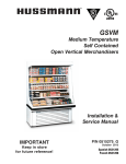
1
Multi-Deck Self Service
Multi-Deck
Self Service
Fresh
Meat Merchandiser
Fresh Meat Merchandiser
FPW-EXA085
FPW-EXA085
FPW-EXA025
FPW-EXA025
INSTALLATION AND SERVICE MANUAL
REMOTE TYPE DISPLAY CASE
TABLE OF CONTENTS
1
SPECIFICATIONS .................................................................................................................................. 4
2
DIMENSIONS........................................................................................................................................ 5
3
4
2.1
EXTERNAL DIMENSIONS...................................................................................................................... 5
2.2
FOOTPRINT........................................................................................................................................ 5
UNLOADING AND CARPENTRY PROCEDURES ................................................................................. 6
3.1
NSF CERTIFICATION ........................................................................................................................... 6
3.2
LOCATION ......................................................................................................................................... 6
3.3
SHIPPING DAMAGE ............................................................................................................................ 6
3.4
UNLOADING INSTRUCTIONS & PRECAUTIONS ........................................................................................ 6
3.5
ALIGNING CASES................................................................................................................................ 7
3.6
CASE LEVELING ................................................................................................................................. 7
3.7
JOINING INSTRUCTIONS ...................................................................................................................... 8
3.7.1
Applying gasket (for connecting cases or installing side panels). ........................................................... 8
3.7.2
Connecting cases. .......................................................................................................................... 9
3.8
INSTALLING PATCH ENDS................................................................................................................... 10
3.9
INSTALLING PRICE TAG MOLDING ....................................................................................................... 11
3.10
INSTALLING KICKPLATE ..................................................................................................................... 11
3.11
INSTALLING HANDRAIL AND BUMPER .................................................................................................. 12
REFRIGERATION, PLUMBING & ELECTRICAL PROCEDURES......................................................... 13
4.1 PIPING (PLUMBING, REFRIGERATION) ................................................................................................... 13
4.2 ELECTRICAL DATA .............................................................................................................................. 14
5
4.3
ELECTRICAL – GUIDELINES & PRECAUTIONS ....................................................................................... 14
4.4
WIRING........................................................................................................................................... 14
4.4.1
Wiring Color Code...................................................................................................................... 14
4.4.2
Wiring Diagram ...................................................................................................................... 15
OPERATION ........................................................................................................................................ 16
5.1
LOAD LIMITS ................................................................................................................................... 16
5.2
INSTALLING FDA/NSF THERMOMETER .............................................................................................. 17
2
6
7
CARE AND CLEANING GUIDELINES................................................................................................. 18
6.1
EXTERIOR PANELS (DAILY CLEANING)................................................................................................. 18
6.2
ACRYLIC SHELF GUARD & PRICE TAG MOLDING (DAILY CLEANING) ...................................................... 18
6.3
SHELF SURFACES (DAILY CLEANING).................................................................................................. 19
6.4
SHELF ASSEMBLIES (WEEKLY CLEANING) ........................................................................................... 19
6.5
MIRRORS, FLUORESCENT LAMPS, DRAIN TRAP (MONTHLY CLEANING) ................................................. 20
6.6
HONEYCOMB ASSEMBLIES (AT LEAST EVERY 3 MONTHS) ..................................................................... 20
SERVICE .............................................................................................................................................. 21
7.1
REPLACING FAN MOTORS AND BLADES.............................................................................................. 21
7.2
REPLACING ELECTRONIC BALLASTS ................................................................................................... 24
7.3
REPLACING FLUORESCENT LAMPS ..................................................................................................... 25
3
1 Specifications
Model Name
FPW-EXA085
FPW-EXA025
Application
Refrigerant
Cooling Capacity
Discharge Air
Evaporator Temperature
Medium Temperature (Meat)
R-404A
1182 BTU/h/ft. (2771W)
31°F (-0.8°C)
24°F (-4.2°C)
Medium Temperature (Meat)
R-404A
1182 BTU/h/ft. (4157W)
31°F (-0.8°C)
24°F (-4.2°C)
Defrost (electric)
Medium Temperature
Medium Temperature
4
50
30
4
50
30
General
Frequency (hr)
Temp Term (°F)
Failsafe (min)
Electrical
1-phase 120V
Anti-condensation Heater
Standard
Fan Motor
Illumination
Interior
Total
(A)
(W)
(A)
N/A
N/A
N/A
N/A
195
2.28
285
3.42
84
1.29
126
1.93
1 row of lamps
N/A
N/A
1 lamp
N/A
N/A
2 rows of lamps
N/A
N/A
2 lamps
N/A
N/A
Top panel
Top panel
High Efficiency
Exterior
1-phase 120V
(W)
Shelves
Total
55
0.47
3-shelf
165
1.41
4-shelf
220
1.88
3-shelf
220
1.88
4-shelf
275
2.35
Shelves
Total
83
0.71
3-shelf
248
2.12
4-shelf
330
2.82
3-shelf
331
2.83
4-shelf
413
3.53
Components
Anti-condensation heater
Fan Motor
Standard
High Efficiency
Fan Blade Pitch
Illumination
Pipe Diameter
Refrigerant Type
N/A
SPFBE141 x 3
SSC2B12CNHBV1 x 3
Inside#128×2 Outside#128 x 1
FO32/XP (T8) (Output 32W)
Liquid ⅜”
Suction ¾”
R-404A
N/A
SPFBE141 x 3 , SPFBE91T x 2
SSC2B12CNHBV1 x 3 , SSC2B12BVHBV1 x 2
Inside#128 x 3 Outside#117 x 2
FO32/XP (T8) (Output 32W)
Liquid ⅜”
Suction ¾”
R-404A
77” (H) × 42 ½” (W) × 96 ⅜” (L)
53 ⅝”
56.0 sq.ft.
58.9 cu.ft.
6 shelves (18” depth)
2 shelves (16” depth), 6 shelves (18” depth)
661 lbs
1 ½”
77” (H) × 42 ½” (W) × 144 ⅝” (L)
53 ⅝”
84.1 sq.ft.
88.4 cu.ft.
9 shelves (18” depth)
3 shelves (16” depth), 9 shelves (18” depth)
992 lbs
1 ½”
Measurements
Outer Dimensions
Open Space
Display Area
Effective Capacity
Shelf
3-shelf
4-shelf
Dimensions
Weight
Waste Outlet Dimensions
Standard Ambient Conditions : Indoor temperature 75°F (24°C), relative humidity 55%, wind speed under 39.4 fpm.
All specifications are based upon temperature, humidity, and wind speed values equal to or less than Standard Ambient Conditions.
Products described in this manual are designed for indoor use only.
Fan motors are available in standard-type (AC fan motors) or high-efficiency type (DC fan motors).
4
Products should not be exposed to direct sunlight.
* Dimensions given in inches and millimeters (mm in parentheses).
2 Dimensions
2.1
External Dimensions
2.2
Footprint
①
②
③
Waste Outlet
Electrical Field Connection
Refrigeration Outlet
3 Unloading and Carpentry Procedures
3.1
NSF Certification
The merchandisers described in this manual are built to meet the requirements of American National Standard/NSF International
Standard 7. Each merchandiser bears a nameplate identifying the type of application for which it was certified:
Type I display refrigerator / freezer: Intended for use in an area where the environmental conditions are controlled and maintained
so that the ambient temperature typically does not exceed 75°F.
3.2
Location
As noted above, the merchandisers described in this manual are design for the display of products in interior spaces with climate
control, with ambient conditions typically maintained below 75°F and 55% relative humidity. Proper merchandiser performance
cannot be guaranteed when ambient temperature and/or humidity exceeds this level.
Merchandisers should not be exposed to direct sunlight or other sources of heat.
Merchandisers should not be exposed to strong air currents, as these may disrupt the dual air curtains used to maintain proper
temperature inside the merchandiser display area.
3.3
Shipping Damage
All equipment should be examined for shipping damage prior to and during offloading. All equipment goes through outgoing
inspection upon leaving our warehouse, and the carrier assumes responsibility for the safe arrival of our merchandisers.
APPARENT DAMAGE: Any obvious loss or damage should be noted immediately at the time of receipt on the freight bill or
express receipt and signed by the carrier’s agent. Failure to do so may lead to rejection of the claim by the carrier.
CONCEALED DAMAGE: If damage that is not apparent during unloading is found after unpacking, retain all packing materials and
submit a written request to the carrier for inspection within 15 days.
LOST ITEMS: Any claims related to lost or missing items must be made to SANYO Commercial Solutions Company within 48
hours of receipt of equipment.
3.4
Unloading Instructions & Precautions
WARNING
Cases are heavy and bulky, and require at least two people for unloading, moving, and installation.
Do not remove the wooden beam from the bottom front edge of each case until the cases have been moved into place in the
store lineup.
Do not walk on the top of the merchandisers. Walking on the top of the merchandiser may lead to serious injury and/or damage
to the merchandiser. Do not place other heavy loads on the top of the merchandiser.
Recommended Practices for Unloading Merchandisers:
1.
Use a J-bar (Johnson bar) to lift one end of the merchandiser.
2.
Insert one or more dollies under the base leg.
3.
Lift the other side with the J-bar.
4.
(Optional) Insert one or more dollies.
5.
Move merchandiser out of container.
6.
Use dollies on both ends of the merchandiser to move to lineup location after unloading from container.
6
3.5
Aligning Cases
WARNING
Cases are heavy and bulky, and require at least two people for unloading, moving, and installation.
Do not walk on the top of the merchandisers. Walking on the top of the merchandiser may lead to serious injury and/or damage
to the merchandiser. Do not place other heavy loads on the top of the merchandiser.
1.
Review layout drawings for spaces where merchandisers are to be installed.
2.
Based on the layout drawings and the merchandiser footprint drawings, mark the floor to indicate the exact locations of the
base legs (back edge and front edge) on each merchandiser. Multiple merchandisers should be aligned based upon the
position of the base legs.
3.
Snap chalk lines for the front and rear positions of the legs on each row of merchandisers.
4.
Mark the location showing the outside edge of each base leg on each merchandiser.
3.6
Case Leveling
Merchandisers must be installed level in order to
ensure proper performance and drainage.
1.
For each lineup of cases to be joined, use a
level (preferably a laser level) to find the
highest point on the front and rear chalk lines
marked in step 3 above (during Case
Alignment).
2.
Determine which of the two points marked
on the line is higher. This is the highest
point in the case lineup.
3.
Estimate the number of shims needed for
the four corners of each case position, in
order to bring all positions to the same height
as the highest point found in step 2.
4.
For each row, place the first merchandiser
case where it will sit over the highest point in
the lineup. Ensure that the case is level,
using shims as needed.
NOTE: Each base leg should rest on solid
supports.
Insert shims as needed if there are any gaps
between the floor and each base leg.
5.
Continue placing cases in the lineup, working outward to both sides from the position of the first case placed.
ensure that all cases in the lineup are level.
7
Use shims to
3.7
3.7.1
Joining Instructions
Applying gasket (for connecting cases or installing side panels).
① Make sure that all merchandisers are resting level.
② Make sure that all required parts for joining are present (gasket, bolts, joint covers, nuts, etc.).
③ Remove shelves, rear interior panels, wire racks, deck pans, and front air grilles from the far right and left ends of each
case being joined.
④ Place gasket along the areas shown in bold in the drawing at right. When connecting two cases, apply gasket to one
case only.
Perimeter gasket is required by NSF.
Do not stretch or twist gasket when applying.
Do not leave gaps.
Gasket ends that are open must be sealed off by applying silicone at the installation site.
Always overlap gasket rather than leaving gaps.
Insufficient or improper sealing may lead to insufficient cooling and condensation.
Gasket
Important for
preventing
condensation.
8
3.7.2
Connecting cases.
① Apply gasket as described above.
② Connect cases by using the attached bolts,
joint covers, and nuts.
Gasket
Silicone seal
Note: Connection point must
be silicone sealed.
Note : To connect exterior top, insert exterior top joint
from rear, and fasten it with screws as shown.
Note: Gasket ends that are open must
be sealed off by applying silicone
at the installation site.
9
3.8
Installing patch ends
①
Gasket
②
M8 Bolts with washers
③
Washers & nuts inside patch end
④
Insulation
⑤
Patch End Cap
⑥
Caps for M8 bolts listed in item 3 above
⑦
Side Cover
2
Before installing left patch end, install cage nut in the
frame at the case side (at position A in the above
drawing).
Manually insert one tab of cage nut in open corner,
and insert the other tab with a screwdriver.
3
Flathead
screwdriver
マイナスドライバー
1.
2.
3.
4.
5.
6.
Apply gasket to case body (per previous instructions).
If present, remove protective film from inside wall of patch
end. Fix washers to outside of patch end with M8 bolts, and
install the patch end on the merchandiser.
Fix washers and nuts (item 3 in above drawing) to the ends of
the M8 bolts inside the merchandiser in the two locations
indicated.
Place insulation over M8 bolt heads outside the patch end.
Cover the M8 bolt heads and insulation outside the patch end
with patch end caps.
Cover ends of M8 bolts inside the merchandiser with caps
(item 6 in above drawing).
NOTE: NSF requires that any bolt or screw in the product area be
capped or cut off. No exposed threads are allowed in the
splash zone. After side panel is attached and bolts have
been tightened, use the provided caps to cover threads
completely for all exposed bolts.
7.
Attach side cover (item 7 in above drawing)
10
角穴
Corner hole
Apply silicone sealant
3.9
Installing price tag molding
1. Remove protective covering from acrylic guard.
2. Attach price tag molding to front of shelf by sliding along the shelf’s front edge.
preparing acrylic guard.
3. Insert acrylic guard into shelf from above.
Note : Price tag mold can fall off shelf unless acrylic guard is inserted fully.
3.10
Installing kickplate
11
Hold in place while
3.11
Installing handrail and bumper
Handrail
Handrail
Attaching the Bumper
1. Attach Maintenance Bumper (length 39-3/8 inches) to bumper brackets over the electrical connection
box (“raceway”) on each merchandiser.
The raceway is located on the right end of each
merchandiser.
2. Attach Full-Length Bumpers between Maintenance Bumpers on separate merchandisers, and also
between Maintenance Bumpers and patch ends.
* Cut Full-Length Bumpers to size on-site.
Cut to correct size so that no gaps remain between pieces.
Attaching the Handrail
1. Starting at one end of merchandiser line-up, attach pieces of Handrail to handrail retainer, butting the
pieces end-to-end without gaps.
2. When you reach the final piece of Handrail to be installed between the last merchandiser in the line-up
and the patch end, cut that piece to length so there are no gaps between handrails or between
handrails and patch ends.
12
4 Refrigeration, Plumbing & Electrical Procedures
4.1
●
Piping (Plumbing, Refrigeration)
U-trap installation
Install U-trap referring to the drawing below.
Part Name
● Sealing the refrigerant pipe opening
Seal pipe completely.
Insufficient sealing may cause the following problems:
•
Insufficient cooling
•
Excessive frost
•
Icing over
•
Condensation on the bottom of case.
13
Part Number
①
Drain Screen
8FL-2-1620-005-00
②
O-ring
8FL-2-6460-001-00
③
Drain Trap
8FL-2-6580-002-00
4.2
Electrical Data
Please refer to Specifications section and nameplate attached to merchandiser for electrical information.
4.3
Electrical – Guidelines & Precautions
All wiring and electrical field work must comply with the National Electrical Code (“NEC”) and other applicable local codes.
All electrical connections must be made inside the raceway area.
4.4
4.4.1
Wiring
Wiring Color Code
14
4.4.2
Wiring Diagram
15
5 Operation
5.1
Load Limits
In order to maintain proper temperature and unit performance, the dual air curtains in each merchandiser must remain
unobstructed:
•
Do not stock shelves beyond the marked load limits.
•
Do not block honeycombs or return air grilles.
•
Do not block airflow in any other way (with signs, tools, packages, etc.)
Failure to follow these precautions will lead to insufficient temperature control, spoilage of stored merchandise, and
excessive frost.
A minimum spacing of 2 inches must be maintained
between the top of merchandise and the bottom of
the shelf above it.
Loading merchandise beyond the maximum level will
result in merchandise touching or entering the cold
air curtain.
16
5.2
Installing FDA/NSF Thermometer
Magnet
Suggested locations for the thermometer required by NSF/ANSI 7 and the FDA Food Code are
indicated above. It is the responsibility of the purchaser/end user of this product to determine the
location within the food storage area that best meets these code requirements .
17
6 Care and Cleaning Guidelines
In order to keep merchandisers sanitary and in good working order, we recommend thorough periodic cleaning as follows:
6.1
Exterior Panels (Daily Cleaning)
a.
Exterior panels should be cleaned with water only.
b.
If required, you may use a mild detergent and warm water to remove stains.
water only in order to prevent discoloration.
c.
Take particular care to clean areas that may be exposed to salt or saline solutions.
d.
DO NOT use scrapers, blades or other sharp objects to remove adhesive, as you may damage panels.
rubbing alcohol to remove adhesive if water and mild detergents alone are insufficient.
6.2
Wet a soft cloth and wring it out to wipe down panels.
You should follow by wiping down with
You may use
Acrylic Shelf Guard & Price Tag Molding (Daily Cleaning)
a.
Grasp shelf guard firmly and pull up.
Keep your eye on the price tag molding, as it may come loose.
b.
Carefully wipe the shelf guard using a soft, damp cloth.
by wiping down each shelf guard with water only.
c.
You may remove the price tag molding easily when the shelf guards are removed.
d.
Wipe down the entire price tag molding, taking care to remove food particles, drips, garbage, dust and any other
foreign substances.
18
You may use a mild detergent, but should complete cleaning
6.3
Shelf Surfaces (Daily Cleaning)
a.
Clean the entire shelf surface, preferably with water only. If required, you may use a mild detergent and warm water
to remove stains. You should follow by wiping down with water only in order to prevent discoloration.
b.
Make sure to clean under mats or objects resting on the shelf surfaces.
6.4
Shelf Assemblies (Weekly Cleaning)
a.
Start shelf assembly cleaning by turning all fluorescent
lamps off.
b.
Remove all shelf guards and price tag molding (see
Section 6.2 above).
c.
Disconnect all fluorescent lamp plugs, pulling by the
terminals. DO NOT PULL ON CORDS.
d.
Remove shelves (see drawings below).
e.
Thoroughly check the underside of each shelf for drips or
other foreign substances and clean.
f.
Clean the entire shelf surface, preferably with water only.
If required, you may use a mild detergent and warm water
to remove stains. You should follow by wiping down with
water only in order to prevent discoloration.
g.
Reset shelves by following the steps above in reverse
order.
WARNING: MAKE SURE ALL FLUORESCENT LAMP PLUGS ARE PLACED FIRMLY IN THEIR SOCKETS.
19
6.5
Mirrors, Fluorescent Lamps, Drain Trap (Monthly Cleaning)
When cleaning mirrors and fluorescent lamps,
1.
Turn off the fluorescent lamps prior to cleaning.
2.
DO NOT place your weight on the shelves.
means to reach them.
If mirrors or lamps are difficult to reach, use a stepladder or other
Clean mirrors with a mild detergent and water, then dry
with a non-abrasive cloth.
Wipe fluorescent lamps with a soft, dry cloth. If
required you may use a water-dampened cloth that has
been squeezed well to remove most moisture. At this
time you may also wish to check for lamps needing
replacing.
Please make sure to check and clean the drain trap at
least once a month. Remove any material that has
gathered in the drain trap and dispose of it. Clean the
drain trap and put it back in its original position.
6.6
Honeycomb Assemblies (At least every 3 months)
Because honeycomb assemblies may deform under pressure, DO NOT use vacuum
cleaners to clean them.
a.
When merchandise is in place under the honeycomb assembles, first cover the
merchandise with a cloth or other material to keep dust from falling.
b.
Remove honeycomb assemblies by pulling down on the wire clips attached to the
assemblies.
c.
Rinse honeycombs in running water in order
to flush out dust, etc. Dust is best removed by
spraying/flushing from the cleaner side toward the
dirtier side.
d.
After thoroughly shaking and drying rinsed
honeycomb assemblies, replace them in their original
positions in the merchandisers.
20
7 Service
7.1
Replacing Fan Motors and Blades
To replace the fan motors:
① Remove the outer air curtain duct cover and socket covers.
② Unplug the fan motor harness and push through hole in plenum.
③ Detach fan motor mounting bracket from plenum and pull up to remove.
21
Fan Motor Assembly Part Codes (Standard-Type Fan Motors)
①Cap nut
②-a
Vibration-damping washer
③Fan blade
②-b
Vibration-damping
washer
②-c
Fan motor
④Motor mount
⑤Bracket
For models with standard-type (AC) fan motors:
No.
Part Name
Model
Part Code
FPW-EXA025
Quantity used
FPW-EXA085
Quantity used
①
Cap nut
-
9FL-2-6450-001-00
5
3
②-a
②-b
②-c
SPFBE141
8FC-4-M140-000-10
3
3
Fan motor
SPFBE91T
8FC-4-M140-000-20
2
-
③
Fan blade
#128
9FL-2-4230-001-00
3
3
#117
9FL-2-4230-002-00
2
-
④
Motor mount
-
9FL-2-8140-001-00
5
3
⑤
Bracket
-
9FL-2-1750-017-01
10
6
22
Fan Motor Assembly Part Codes (High-Efficiency-Type Fan Motors)
① Cap nut
②-a
Vibration-damping washer
③ Fan blade
②-b Fan motor
④ Bracket
For models with high-efficiency-type (DC) fan motors:
No.
Part Name
Model
Part Code
FPW-EXA025
Quantity used
FPW-EXA085
Quantity used
①
Cap nut
-
9FL-2-6450-001-00
5
3
②-a
②-b
Fan motor
SSC2B12CNHBV1
8FC-4-M110-000-10
3
3
SSC2B12BVHBV1
8FC-4-M110-000-20
2
-
③
Fan blade
#128
9FL-2-4230-001-00
3
3
#117
9FL-2-4230-002-00
2
-
-
9FL-2-1750-017-01
10
6
④
Bracket
23
7.2
Replacing Electronic Ballasts
To replace electronic ballasts:
① Remove the Exterior Top Panel.
② Unplug the electronic ballast harness(es).
③ Remove the electronic ballast(s).
Electronic Ballast Part Codes
Type
Model
Part Code
FPW-EXA025
Quantity used
FPW-EXA085
Quantity used
4-lamp
QHE4X32T8/UNV ISN-SC-1-CC-B
8FC-0-5400-000-40-1
3
2
3-lamp
QHE3X32T8/UNV ISN-SC-1-CC-B
8FC-0-5400-000-30-1
1
-
2-lamp
QHE2X32T8/UNV ISN-SC-1-CC-B
8FC-0-5400-000-20-1
-
1
24
7.3
Replacing Fluorescent Lamps
The unit comes with covers placed over each fluorescent lamp. Ensure that these covers are placed over the new lamps
before reinstallation.
LAMP COVER
END CAP
LAMP
NOTICE!
Always use Sanyo lamp covers and end caps when replacing lamp covers and end caps.
Using non-Sanyo brand replacement parts can result in decreased performance and/or part lifetime.
25
26
27
MDMN 001.04
July 2008