1
FILE NO. SVM-13024-3
SERVICE MANUAL
AIR-CONDITIONER (MULTI TYPE)
<SUPER MODULAR MULTI SYSTEM - i>
Outdoor Unit
Model name:
<Heat Pump Model>
MMY-MAP0804HT8(J)P
MMY-MAP1004HT8(J)P
MMY-MAP1204HT8(J)P
MMY-MAP1404HT8(J)P
MMY-MAP1604HT8(J)P
MMY-MAP0804HT8(J)P-E
MMY-MAP1004HT8(J)P-E
MMY-MAP1204HT8(J)P-E
MMY-MAP1404HT8(J)P-E
MMY-MAP1604HT8(J)P-E
MMY-MAP0804HT8(J)P-TR
MMY-MAP1004HT8(J)P-TR
MMY-MAP1204HT8(J)P-TR
MMY-MAP1404HT8(J)P-TR
MMY-MAP1604HT8(J)P-TR
<Cooling Only Model>
MMY-MAP0804T8(J)P
MMY-MAP1004T8(J)P
MMY-MAP1204T8(J)P
MMY-MAP1404T8(J)P
MMY-MAP1604T8(J)P
MMY-MAP0804T8(J)P-T
MMY-MAP1004T8(J)P-T
MMY-MAP1204T8(J)P-T
MMY-MAP1404T8(J)P-T
MMY-MAP1604T8(J)P-T
MMY-MAP0804T8(J)P-SG
MMY-MAP1004T8(J)P-SG
MMY-MAP1204T8(J)P-SG
MMY-MAP1404T8(J)P-SG
MMY-MAP1604T8(J)P-SG
MMY-MAP0804T8(J)P-ID
MMY-MAP1004T8(J)P-ID
MMY-MAP1204T8(J)P-ID
MMY-MAP1404T8(J)P-ID
MMY-MAP1604T8(J)P-ID
MMY-MAP0804T8(J)P-E
MMY-MAP1004T8(J)P-E
MMY-MAP1204T8(J)P-E
MMY-MAP1404T8(J)P-E
MMY-MAP1604T8(J)P-E
MMY-MAP0804HT7(J)P
MMY-MAP1004HT7(J)P
MMY-MAP1204HT7(J)P
MMY-MAP1404HT7(J)P
MMY-MAP1604HT7(J)P
This service manual provides relevant explanations about new outdoor unit (SMMS-i).
Please refer to the following service manuals for each indoor units.
<4-way Cassette Type>
(MMU-AP***4HP-E) (Made in Thailand model)
SVM-13-011
<2-way Cassette Type>
(MMU-AP***2WH)
A10-007
<Concealed Duct Standard Type>
(MMD-AP***6BH-E)
A12-005
<Slim Duct Type>
(MMD-AP0244SPH-E, AP0274SPH-E)
A12-005
Fresh Air Intake Indoor Unit Type
(MMD-AP****HFE)
A06-016
<Air to Air Heat Exchanger with DX Coil Unit Type>
(MMD-VN*****HEXE*)
A10-022-2
High-wall Type
(MMK-AP***3H)
(Made in Thailand model)
SVM-09-059
Console Type
(MML-AP****NH-E)
(Made in Thailand model)
SVM-11-036
Other indoor units
(MM*-AP*****H*)
A10-033
Contents
SAFETY CAUTION . . . . . . . . . . . . . . . . . . . . . . . . . . . . . . . . . . . . . . . . . . . . . . . . . . . . 5
New Refrigerant (R410A) . . . . . . . . . . . . . . . . . . . . . . . . . . . . . . . . . . . . . . . . . . . . . . 20
1
Wiring Diagrams . . . . . . . . . . . . . . . . . . . . . . . . . . . . . . . . . . . . . . . . . . . . . . . . . . . . . 22
1-1.
1-2.
2
Outdoor Unit . . . . . . . . . . . . . . . . . . . . . . . . . . . . . . . . . . . . . . . . . . . . . . . . . . . . . . . . . . . . . . . . .
Indoor Unit . . . . . . . . . . . . . . . . . . . . . . . . . . . . . . . . . . . . . . . . . . . . . . . . . . . . . . . . . . . . . . . . . .
1-2-1. 4-way Cassette Type . . . . . . . . . . . . . . . . . . . . . . . . . . . . . . . . . . . . . . . . . . . . . . . . . . . .
1-2-2. Compact 4-way Cassette Type . . . . . . . . . . . . . . . . . . . . . . . . . . . . . . . . . . . . . . . . . . . .
1-2-3. 1-way Cassette Type (Compact type) . . . . . . . . . . . . . . . . . . . . . . . . . . . . . . . . . . . . . . .
1-2-4. 1-way Cassette Type SH series . . . . . . . . . . . . . . . . . . . . . . . . . . . . . . . . . . . . . . . . . . .
1-2-5. 2-way Cassette Type 2 series . . . . . . . . . . . . . . . . . . . . . . . . . . . . . . . . . . . . . . . . . . . . .
1-2-6. Concealed Duct Standard Type . . . . . . . . . . . . . . . . . . . . . . . . . . . . . . . . . . . . . . . . . . . .
1-2-7. Concealed Duct Standard Type 6 series . . . . . . . . . . . . . . . . . . . . . . . . . . . . . . . . . . . . .
1-2-8. Concealed Duct High Static Pressure Type . . . . . . . . . . . . . . . . . . . . . . . . . . . . . . . . . .
1-2-9. Slim Duct Type . . . . . . . . . . . . . . . . . . . . . . . . . . . . . . . . . . . . . . . . . . . . . . . . . . . . . . . .
1-2-10. Slim Duct Type (AP024, AP027) . . . . . . . . . . . . . . . . . . . . . . . . . . . . . . . . . . . . . . . . . . .
1-2-11. Ceiling Type . . . . . . . . . . . . . . . . . . . . . . . . . . . . . . . . . . . . . . . . . . . . . . . . . . . . . . . . . . .
1-2-12. High Wall Type 4MH series . . . . . . . . . . . . . . . . . . . . . . . . . . . . . . . . . . . . . . . . . . . . . . .
1-2-13. High Wall Type 3 series . . . . . . . . . . . . . . . . . . . . . . . . . . . . . . . . . . . . . . . . . . . . . . . . . .
1-2-14. Floor Standing Cabinet Type . . . . . . . . . . . . . . . . . . . . . . . . . . . . . . . . . . . . . . . . . . . . . .
1-2-15. Floor Standing Concealed Type . . . . . . . . . . . . . . . . . . . . . . . . . . . . . . . . . . . . . . . . . . .
1-2-16. Floor Standing Type . . . . . . . . . . . . . . . . . . . . . . . . . . . . . . . . . . . . . . . . . . . . . . . . . . . .
1-2-17. Air to Air Heat Exchanger with DX Coil Unit . . . . . . . . . . . . . . . . . . . . . . . . . . . . . . . . . .
1-2-18. Fresh Air Intake Indoor Unit . . . . . . . . . . . . . . . . . . . . . . . . . . . . . . . . . . . . . . . . . . . . . . .
22
24
24
25
26
27
28
29
30
31
33
34
35
36
37
38
39
40
41
45
Parts Rating . . . . . . . . . . . . . . . . . . . . . . . . . . . . . . . . . . . . . . . . . . . . . . . . . . . . . . . . . 47
2-1.
2-2.
2-3.
2-4.
2-5.
2-6.
2-7.
Outdoor Unit (50Hz model: MMY-MAP***4*T8*P*) . . . . . . . . . . . . . . . . . . . . . . . . . . . . . . . . . .
Outdoor Unit (60Hz model: MMY-MAP***4HT7*P) . . . . . . . . . . . . . . . . . . . . . . . . . . . . . . . . . .
Outdoor Inverter (50Hz model: MMY-MAP***4*T8*P*) . . . . . . . . . . . . . . . . . . . . . . . . . . . . . . .
Outdoor Inverter (60Hz model: MMY-MAP***4HT7*P). . . . . . . . . . . . . . . . . . . . . . . . . . . . . . . .
Parts Layout in Outdoor Unit . . . . . . . . . . . . . . . . . . . . . . . . . . . . . . . . . . . . . . . . . . . . . . . . . . . .
Parts Layout in Inverter Assembly . . . . . . . . . . . . . . . . . . . . . . . . . . . . . . . . . . . . . . . . . . . . . . . .
Outdoor (Inverter) Print Circuit Board . . . . . . . . . . . . . . . . . . . . . . . . . . . . . . . . . . . . . . . . . . . . .
2-7-1. Interface P.C. board (MCC-1606) . . . . . . . . . . . . . . . . . . . . . . . . . . . . . . . . . . . . . . . . . .
2-7-2. Inverter P.C. board for compressor (MCC-1596) A3-IPDU . . . . . . . . . . . . . . . . . . . . . . .
2-7-3. Inverter P.C. board for fan (MCC-1610) . . . . . . . . . . . . . . . . . . . . . . . . . . . . . . . . . . . . .
47
48
49
50
51
53
55
55
56
57
3
Refrigerant Piping Systematic Drawing . . . . . . . . . . . . . . . . . . . . . . . . . . . . . . . . . . 58
4
Combined Refrigerant Piping System Schematic Diagrams . . . . . . . . . . . . . . . . . 62
4-1.
4-2.
4-3.
4-4.
4-5.
4-6.
Normal Operation (COOL Mode / DEFROST Mode) High Outside Air Temperature (Roughly 20°C or Above) . . . . . . . . . . . . . . . . . . . . . . . . . . . . . .
Normal Operation (COOL Mode) - Low Outside Air Temperature (Roughly Below 20°C). . . . . .
Normal Operation (HEAT Mode) . . . . . . . . . . . . . . . . . . . . . . . . . . . . . . . . . . . . . . . . . . . . . . . . .
Emergency Operation (Cooling Operation under Header Outdoor Unit Backup Scenario) . . . . .
Emergency Operation (Heating Operation under Header Outdoor Unit Backup Scenario) . . . . .
Refrigerant Recovery from Failed Outdoor Unit (Pump-Down Operation under
Follower Outdoor Unit Backup Scenario) . . . . . . . . . . . . . . . . . . . . . . . . . . . . . . . . . . . . . . . . . . .
–1–
62
63
64
65
66
67
5
Control Outline . . . . . . . . . . . . . . . . . . . . . . . . . . . . . . . . . . . . . . . . . . . . . . . . . . . . . . 68
6
Applied Control and Functions (including Circuit Configuration) . . . . . . . . . . . . . 83
6-1.
6-2.
6-3.
6-4.
6-5.
6-6.
6-7.
6-8.
7
Indoor Controller Block Diagram . . . . . . . . . . . . . . . . . . . . . . . . . . . . . . . . . . . . . . . . . . . . . . . . . 83
6-1-1. When Wired (Simple) Remote Controller Connected . . . . . . . . . . . . . . . . . . . . . . . . . . . 83
6-1-2. When Wireless Remote Controller Kit Connected . . . . . . . . . . . . . . . . . . . . . . . . . . . . . . 86
6-1-3. When Both Main (Sub) Remote Controller and Wireless Remote Controller
Kit Connected . . . . . . . . . . . . . . . . . . . . . . . . . . . . . . . . . . . . . . . . . . . . . . . . . . . . . . . . . 89
Indoor Printed Circuit Board . . . . . . . . . . . . . . . . . . . . . . . . . . . . . . . . . . . . . . . . . . . . . . . . . . . . . 92
Optional Connector Specifications of Indoor P.C. Board . . . . . . . . . . . . . . . . . . . . . . . . . . . . . . . 95
Test Operation of Indoor Unit . . . . . . . . . . . . . . . . . . . . . . . . . . . . . . . . . . . . . . . . . . . . . . . . . . . . 96
Method to Set Indoor Unit Function DN Code . . . . . . . . . . . . . . . . . . . . . . . . . . . . . . . . . . . . . . . 97
Applied Control of Indoor Unit . . . . . . . . . . . . . . . . . . . . . . . . . . . . . . . . . . . . . . . . . . . . . . . . . . 101
Applied control for Outdoor Unit . . . . . . . . . . . . . . . . . . . . . . . . . . . . . . . . . . . . . . . . . . . . . . . . . 104
6-7-1. Outdoor Fan High Static Pressure Shift . . . . . . . . . . . . . . . . . . . . . . . . . . . . . . . . . . . . . 104
6-7-2. Priority Operation Mode Setting . . . . . . . . . . . . . . . . . . . . . . . . . . . . . . . . . . . . . . . . . . . 105
Applied Control of Outdoor Unit . . . . . . . . . . . . . . . . . . . . . . . . . . . . . . . . . . . . . . . . . . . . . . . . . 107
6-8-1. Power peak-cut Control (Standard) . . . . . . . . . . . . . . . . . . . . . . . . . . . . . . . . . . . . . . . . 108
6-8-2. Power peak-cut Control (Extended) . . . . . . . . . . . . . . . . . . . . . . . . . . . . . . . . . . . . . . . . 109
6-8-3. Snowfall Fan Control . . . . . . . . . . . . . . . . . . . . . . . . . . . . . . . . . . . . . . . . . . . . . . . . . . . 110
6-8-4. External master ON/OFF Control . . . . . . . . . . . . . . . . . . . . . . . . . . . . . . . . . . . . . . . . . 110
6-8-5. Night operation (sound reduction) Control . . . . . . . . . . . . . . . . . . . . . . . . . . . . . . . . . . . 111
6-8-6. Operation Mode Selection Control . . . . . . . . . . . . . . . . . . . . . . . . . . . . . . . . . . . . . . . . . 112
6-8-7. Error/Operation Output . . . . . . . . . . . . . . . . . . . . . . . . . . . . . . . . . . . . . . . . . . . . . . . . . 113
6-8-8. Compressor Operation Output . . . . . . . . . . . . . . . . . . . . . . . . . . . . . . . . . . . . . . . . . . . . 114
6-8-9. Operating Rate Output . . . . . . . . . . . . . . . . . . . . . . . . . . . . . . . . . . . . . . . . . . . . . . . . . . 115
TEST OPERATION . . . . . . . . . . . . . . . . . . . . . . . . . . . . . . . . . . . . . . . . . . . . . . . . . . 116
7-1.
7-2.
7-3.
7-4.
7-5.
7-6.
Procedure and Summary of Test Operation . . . . . . . . . . . . . . . . . . . . . . . . . . . . . . . . . . . . . . .
Check Items before Test Operation (before powering-on) . . . . . . . . . . . . . . . . . . . . . . . . . . . . .
Check at Main Power-on . . . . . . . . . . . . . . . . . . . . . . . . . . . . . . . . . . . . . . . . . . . . . . . . . . . . . .
Address Setup . . . . . . . . . . . . . . . . . . . . . . . . . . . . . . . . . . . . . . . . . . . . . . . . . . . . . . . . . . . . . .
7-4-1. Precautions . . . . . . . . . . . . . . . . . . . . . . . . . . . . . . . . . . . . . . . . . . . . . . . . . . . . . . . . . .
7-4-2. Address Setup and Check Procedure . . . . . . . . . . . . . . . . . . . . . . . . . . . . . . . . . . . . . .
7-4-3. Address Setup Procedure . . . . . . . . . . . . . . . . . . . . . . . . . . . . . . . . . . . . . . . . . . . . . . .
7-4-4. Check after Address Setup when Central Control System Is Connected . . . . . . . . . . .
Troubleshooting in Test Operation . . . . . . . . . . . . . . . . . . . . . . . . . . . . . . . . . . . . . . . . . . . . . . .
7-5-1. A Check Code is Displayed on the Remote Controller . . . . . . . . . . . . . . . . . . . . . . . . .
7-5-2. Operation from the indoor remote controller is not accepted, and a check code is
displayed on the 7-segment display of the interface PC board of the header unit. . . . .
7-5-3. There is no display of a check code on the 7-segment display on the interface
PC board of the header unit, although there is indoor unit that is not accepting
operation from the indoor remote controller. . . . . . . . . . . . . . . . . . . . . . . . . . . . . . . . . .
7-5-4. In checking the number of connected outdoor units and connected indoor units
after address setup, a lower number of connected units is displayed. (There are
outdoor/indoor units that do not operate in a test operation.) . . . . . . . . . . . . . . . . . . . .
Test Operation Check . . . . . . . . . . . . . . . . . . . . . . . . . . . . . . . . . . . . . . . . . . . . . . . . . . . . . . . .
7-6-1. Fan Check . . . . . . . . . . . . . . . . . . . . . . . . . . . . . . . . . . . . . . . . . . . . . . . . . . . . . . . . . . .
7-6-2. Single cooling/Single heating Test Operation Check . . . . . . . . . . . . . . . . . . . . . . . . . . .
–2–
116
117
121
122
122
122
123
136
137
137
138
138
139
141
141
142
7-7.
8
Service Support Function . . . . . . . . . . . . . . . . . . . . . . . . . . . . . . . . . . . . . . . . . . . . . . . . . . . . . .
7-7-1. Check Function for Connecting of Refrigerant and Control Lines . . . . . . . . . . . . . . . . .
7-7-2. Function to Start/Stop (ON/OFF) Indoor Unit from Outdoor Unit . . . . . . . . . . . . . . . . . .
7-7-3. Error Clearing Function . . . . . . . . . . . . . . . . . . . . . . . . . . . . . . . . . . . . . . . . . . . . . . . . .
7-7-4. Remote Controller Distinction Function . . . . . . . . . . . . . . . . . . . . . . . . . . . . . . . . . . . . .
7-7-5. Pulse Motor Valve (PMV) Forced Open/Close Function in Indoor Unit . . . . . . . . . . . . .
7-7-6. Pulse Motor Valve (PMV) Forced Open Fully/Close fully Function in Outdoor Unit . . .
7-7-7. Solenoid Valve Forced Open/Close Function in Outdoor Unit . . . . . . . . . . . . . . . . . . . .
7-7-8. Fan Operation Check in Outdoor Unit . . . . . . . . . . . . . . . . . . . . . . . . . . . . . . . . . . . . . .
7-7-9. Abnormal Outdoor Unit Discrimination Method By Fan Operating Function . . . . . . . . .
7-7-10. Manual Adjustment Function of Outside Temperature (TO) Sensor . . . . . . . . . . . . . . .
7-7-11. Monitor Function of Remote Controller Switch . . . . . . . . . . . . . . . . . . . . . . . . . . . . . . .
TROUBLESHOOTING . . . . . . . . . . . . . . . . . . . . . . . . . . . . . . . . . . . . . . . . . . . . . . . . 164
8-1.
8-2.
8-3.
8-4.
Overview . . . . . . . . . . . . . . . . . . . . . . . . . . . . . . . . . . . . . . . . . . . . . . . . . . . . . . . . . . . . . . . . . .
Troubleshooting Method . . . . . . . . . . . . . . . . . . . . . . . . . . . . . . . . . . . . . . . . . . . . . . . . . . . . . .
Troubleshooting Based on Information Displayed on Remote Controller . . . . . . . . . . . . . . . . .
Check Codes Displayed on Remote Controller and SMMS-i Outdoor Unit
(7-Segment Display on I/F Board) and Locations to Be Checked . . . . . . . . . . . . . . . . . . . . . . .
8-5. Diagnosis procedure for each check code . . . . . . . . . . . . . . . . . . . . . . . . . . . . . . . . . . . . . . . . .
8-6. 7-Segment Display Function . . . . . . . . . . . . . . . . . . . . . . . . . . . . . . . . . . . . . . . . . . . . . . . . . . .
8-7. Oil Level Judgment Display . . . . . . . . . . . . . . . . . . . . . . . . . . . . . . . . . . . . . . . . . . . . . . . . . . . .
8-8. Leakage/Clogging of Refrigerating Cycle Circuit . . . . . . . . . . . . . . . . . . . . . . . . . . . . . . . . . . . .
8-9. Sensor Characteristics . . . . . . . . . . . . . . . . . . . . . . . . . . . . . . . . . . . . . . . . . . . . . . . . . . . . . . . .
8-10. Pressure Sensor Output Check . . . . . . . . . . . . . . . . . . . . . . . . . . . . . . . . . . . . . . . . . . . . . . . . .
9
146
146
148
153
155
156
156
157
158
159
160
162
164
165
171
176
192
223
229
230
234
237
BACKUP OPERATION
(EMERGENCY OPERATION) . . . . . . . . . . . . . . . . . . . . . . . . . . . . . . . . . . . . . . . . . . 239
9-1.
9-2.
9-3.
9-4.
Note for Backup Operation . . . . . . . . . . . . . . . . . . . . . . . . . . . . . . . . . . . . . . . . . . . . . . . . . . . .
Compressor Backup Operation Setting . . . . . . . . . . . . . . . . . . . . . . . . . . . . . . . . . . . . . . . . . . .
Outdoor Unit Backup Operation Setting . . . . . . . . . . . . . . . . . . . . . . . . . . . . . . . . . . . . . . . . . . .
9-3-1. Follower outdoor unit backup operation setting (failure of follower outdoor unit) . . . . .
9-3-2. Header outdoor unit backup operation setting (failure of header outdoor unit) . . . . . . .
Cooling-Season Outdoor Unit Backup Operation Setting . . . . . . . . . . . . . . . . . . . . . . . . . . . . .
239
240
241
241
243
245
10 OUTDOOR UNIT REFRIGERANT RECOVERY METHOD . . . . . . . . . . . . . . . . . . . . 246
10-1. Refrigerant Recovery from Failed Outdoor Unit (Pump-Down) . . . . . . . . . . . . . . . . . . . . . . . . .
10-1-1. Note for refrigerant recovery operation . . . . . . . . . . . . . . . . . . . . . . . . . . . . . . . . . . . . .
10-1-2. Refrigerant recovery procedure A (Case of no outdoor unit backup operation setting)
10-1-3. Refrigerant recovery procedure B (Case of outdoor unit backup operation setting) . . .
10-2. How to Operate System While Failed Outdoor Unit Being Repaired . . . . . . . . . . . . . . . . . . . . .
10-3. Work procedure after Repair . . . . . . . . . . . . . . . . . . . . . . . . . . . . . . . . . . . . . . . . . . . . . . . . . . .
246
246
246
249
251
252
11 REPLACING COMPRESSORS . . . . . . . . . . . . . . . . . . . . . . . . . . . . . . . . . . . . . . . . . 253
11-1. Compressor Replacement Procedure (Outline) . . . . . . . . . . . . . . . . . . . . . . . . . . . . . . . . . . . . . 253
11-2. Replacement of Compressors . . . . . . . . . . . . . . . . . . . . . . . . . . . . . . . . . . . . . . . . . . . . . . . . . . 254
11-3. Check Procedure to Search Cause of Compressor Oil Shortage . . . . . . . . . . . . . . . . . . . . . . . 259
–3–
12 OUTDOOR UNIT PARTS REPLACEMENT METHODS . . . . . . . . . . . . . . . . . . . . . . 262
13 P.C. BOARD EXCHANGE PROCEDURES . . . . . . . . . . . . . . . . . . . . . . . . . . . . . . . . 275
13-1. Replacement of Indoor P.C. Boards . . . . . . . . . . . . . . . . . . . . . . . . . . . . . . . . . . . . . . . . . . . . .
13-2. Replacement of Outdoor P.C. Boards . . . . . . . . . . . . . . . . . . . . . . . . . . . . . . . . . . . . . . . . . . . .
13-2-1. List of service P.C. boards . . . . . . . . . . . . . . . . . . . . . . . . . . . . . . . . . . . . . . . . . . . . . . .
13-2-2. Configuration of inverter assembly . . . . . . . . . . . . . . . . . . . . . . . . . . . . . . . . . . . . . . . .
13-2-3. Interface board (MCC-1606) replacement method . . . . . . . . . . . . . . . . . . . . . . . . . . . .
13-2-4. Comp-IPDU P.C. Board (MCC-1596) Replacement Procedure . . . . . . . . . . . . . . . . . .
13-2-5. Fan IPDU P.C. Board (MCC-1610) Replacement Procedure . . . . . . . . . . . . . . . . . . . .
13-2-6. Noise Filter P.C. Board (MCC-1608 A, B) Replacement Procedure . . . . . . . . . . . . . . .
275
282
282
282
283
284
286
287
14 EXPLODED DIAGRAM/PARTS LIST . . . . . . . . . . . . . . . . . . . . . . . . . . . . . . . . . . . . 290
–4–
SAFETY CAUTION
Please read carefully through these instructions that contain important information which complies with the
“Machinery” Directive (Directive 2006/42/EC), and ensure that you understand them.
Some of the details provided in these instructions differ from the service manual, and the instructions provided
here take precedence.
Generic Denomination: Air Conditioner
Definition of Qualified Installer or Qualified Service Person
The air conditioner must be installed, maintained, repaired and removed by a qualified installer or qualified
service person. When any of these jobs is to be done, ask a qualified installer or qualified service person to do
them for you.
A qualified installer or qualified service person is an agent who has the qualifications and knowledge
described in the table below.
Agent
Qualified installer
Qualified service
person
Qualifications and knowledge which the agent must have
• The qualified installer is a person who installs, maintains, relocates and removes the air
conditioners made by Toshiba Carrier Corporation. He or she has been trained to install,
maintain, relocate and remove the air conditioners made by Toshiba Carrier Corporation or,
alternatively, he or she has been instructed in such operations by an individual or individuals
who have been trained and is thus thoroughly acquainted with the knowledge related to these
operations.
• The qualified installer who is allowed to do the electrical work involved in installation, relocation
and removal has the qualifications pertaining to this electrical work as stipulated by the local
laws and regulations, and he or she is a person who has been trained in matters relating to
electrical work on the air conditioners made by Toshiba Carrier Corporation or, alternatively, he
or she has been instructed in such matters by an individual or individuals who have been
trained and is thus thoroughly acquainted with the knowledge related to this work.
• The qualified installer who is allowed to do the refrigerant handling and piping work involved in
installation, relocation and removal has the qualifications pertaining to this refrigerant handling
and piping work as stipulated by the local laws and regulations, and he or she is a person who
has been trained in matters relating to refrigerant handling and piping work on the air
conditioners made by Toshiba Carrier Corporation or, alternatively, he or she has been
instructed in such matters by an individual or individuals who have been trained and is thus
thoroughly acquainted with the knowledge related to this work.
• The qualified installer who is allowed to work at heights has been trained in matters relating to
working at heights with the air conditioners made by Toshiba Carrier Corporation or,
alternatively, he or she has been instructed in such matters by an individual or individuals who
have been trained and is thus thoroughly acquainted with the knowledge related to this work.
• The qualified service person is a person who installs, repairs, maintains, relocates and removes
the air conditioners made by Toshiba Carrier Corporation. He or she has been trained to install,
repair, maintain, relocate and remove the air conditioners made by Toshiba Carrier Corporation
or, alternatively, he or she has been instructed in such operations by an individual or individuals
who have been trained and is thus thoroughly acquainted with the knowledge related to these
operations.
• The qualified service person who is allowed to do the electrical work involved in installation,
repair, relocation and removal has the qualifications pertaining to this electrical work as
stipulated by the local laws and regulations, and he or she is a person who has been trained in
matters relating to electrical work on the air conditioners made by Toshiba Carrier Corporation
or, alternatively, he or she has been instructed in such matters by an individual or individuals
who have been trained and is thus thoroughly acquainted with the knowledge related to this
work.
• The qualified service person who is allowed to do the refrigerant handling and piping work
involved in installation, repair, relocation and removal has the qualifications pertaining to this
refrigerant handling and piping work as stipulated by the local laws and regulations, and he or
she is a person who has been trained in matters relating to refrigerant handling and piping work
on the air conditioners made by Toshiba Carrier Corporation or, alternatively, he or she has
been instructed in such matters by an individual or individuals who have been trained and is
thus thoroughly acquainted with the knowledge related to this work.
• The qualified service person who is allowed to work at heights has been trained in matters
relating to working at heights with the air conditioners made by Toshiba Carrier Corporation or,
alternatively, he or she has been instructed in such matters by an individual or individuals who
have been trained and is thus thoroughly acquainted with the knowledge related to this work.
–5–
Definition of Protective Gear
When the air conditioner is to be transported, installed, maintained, repaired or removed, wear protective
gloves and ‘safety’ work clothing.
In addition to such normal protective gear, wear the protective gear described below when undertaking the
special work detailed in the table below.
Failure to wear the proper protective gear is dangerous because you will be more susceptible to injury, burns,
electric shocks and other injuries.
Work undertaken
Protective gear worn
All types of work
Protective gloves
‘Safety’ working clothing
Electrical-related work
Gloves to provide protection for electricians and from heat
Insulating shoes
Clothing to provide protection from electric shock
Work done at heights
(50 cm or more)
Helmets for use in industry
Transportation of heavy objects
Shoes with additional protective toe cap
Repair of outdoor unit
Gloves to provide protection for electricians and from heat
The important contents concerned to the safety are described on the product itself and on this Service
Manual.
Please read this Service Manual after understanding the described items thoroughly in the following contents
(Indications / Illustrated marks), and keep them.
[Explanation of indications]
Indication
Explanation
DANGER
Indicates contents assumed that an imminent danger causing a death or serious injury of
the repair engineers and the third parties when an incorrect work has been executed.
WARNING
Indicates possibilities assumed that a danger causing a death or serious injury of the
repair engineers, the third parties, and the users due to troubles of the product after work
when an incorrect work has been executed.
CAUTION
Indicates contents assumed that an injury or property damage (*) may be caused on the
repair engineers, the third parties, and the users due to troubles of the product after work
when an incorrect work has been executed.
* Property damage: Enlarged damage concerned to property, furniture, and domestic animal / pet
[Explanation of illustrated marks]
Indication
Explanation
Indicates prohibited items (Forbidden items to do)
The sentences near an illustrated mark describe the concrete prohibited contents.
Indicates mandatory items (Compulsory items to do)
The sentences near an illustrated mark describe the concrete mandatory contents.
Indicates cautions (Including danger / warning)
The sentences or illustration near or in an illustrated mark describe the concrete cautious contents.
–6–
Warning Indications on the Air Conditioner Unit
[Confirmation of warning label on the main unit]
Confirm that labels are indicated on the specified positions
If removing the label during parts replace, stick it as the original.
Warning indication
Description
WARNING
WARNING
ELECTRICAL SHOCK HAZARD
Disconnect all remote electric
power supplies before servicing.
WARNING
ELECTRICAL SHOCK HAZARD
Disconnect all remote electric power supplies
before servicing.
WARNING
Moving parts.
Do not operate unit with grille removed.
Stop the unit before the servicing.
CAUTION
Moving parts.
Do not operate unit with grille removed.
Stop the unit before the servicing.
CAUTION
High temperature parts.
You might get burned when removing this panel.
High temperature parts.
You might get burned when removing
this panel.
CAUTION
CAUTION
Do not touch the aluminium fins of the unit.
Doing so may result in injury.
CAUTION
Do not touch the aluminium fins of the unit.
Doing so may result in injury.
CAUTION
BURST HAZARD
BURST HAZARD
Open the service valves before the
operation, otherwise there might be the
burst.
CAUTION
Open the service valves before the operation,
otherwise there might be the burst.
CAUTION
Do not climb onto the fan guard.
Do not climb onto the fan guard.
Doing so may result in injury.
Doing so may result in injury.
–7–
PRECAUTIONS FOR SAFETY
The manufacturer shall not assume any liability for the damage caused by not observing the description of this
manual.
DANGER
Before carrying out the installation, maintenance, repair or removal work, be sure to set the circuit
breaker for both the indoor and outdoor units to the OFF position. Otherwise, electric shocks may
result.
Before opening the intake grille of the indoor unit or service panel of the outdoor unit, set the circuit
breaker to the OFF position.
Failure to set the circuit breaker to the OFF position may result in electric shocks through contact with
the interior parts.
Only a qualified installer (*1) or qualified service person (*1) is allowed to remove the intake grille of the
indoor unit or service panel of the outdoor unit and do the work required.
Before starting to repair the outdoor unit fan or fan guard, be absolutely sure to set the circuit breaker
to the OFF position, and place a “Work in progress” sign on the circuit breaker.
Turn off
braeaker
When cleaning the filter or other parts of the indoor unit, set the circuit breaker to OFF without fail, and
place a “Work in progress” sign near the circuit breaker before proceeding with the work.
When you have noticed that some kind of trouble (such as when an error display has appeared, there
is a smell of burning, abnormal sounds are heard, the air conditioner fails to cool or heat or water is
leaking) has occurred in the air conditioner, do not touch the air conditioner yourself but set the circuit
breaker to the OFF position, and contact a qualified service person. Take steps to ensure that the
power will not be turned on (by marking “out of service” near the circuit breaker, for instance) until
qualified service person arrives. Continuing to use the air conditioner in the trouble status may cause
mechanical problems to escalate or result in electric shocks or other failure.
Electric
shock hazard
When you access inside of the service panel to repair electric parts, wait for about five minutes after turning
off the breaker. Do not start repairing immediately.Otherwise you may get electric shock by touching
terminals of high-voltage capacitors. Natural discharge of the capacitor takes about five minutes.
Place a “Work in progress” sign near the circuit breaker while the installation, maintenance, repair or
removal work is being carried out.
There is a danger of electric shocks if the circuit breaker is set to ON by mistake.
Prohibition
Stay on
protection
Before operating the air conditioner after having completed the work, check that the electrical parts box
cover of the indoor unit and service panel of the outdoor unit are closed, and set the circuit breaker to
the ON position.
You may receive an electric shock if the power is turned on without first conducting these checks.
If, in the course of carrying out repairs, it becomes absolutely necessary to check out the electrical
parts with the electrical parts box cover of one or more of the indoor units and the service panel of the
outdoor unit removed in order to find out exactly where the trouble lies, wear insulated heat-resistant
gloves, insulated boots and insulated work overalls, and take care to avoid touching any live parts.
You may receive an electric shock if you fail to heed this warning. Only qualified service person (*1) is
allowed to do this kind of work.
–8–
WARNING
Before starting to repair the air conditioner, read carefully through the Service Manual, and repair the
air conditioner by following its instructions.
Only qualified service person (*1) is allowed to repair the air conditioner.
Repair of the air conditioner by unqualified person may give rise to a fire, electric shocks, injury, water
leaks and / or other problems.
Do not use any refrigerant different from the one specified for complement or replacement.
Otherwise, abnormally high pressure may be generated in the refrigeration cycle, which may result in a
failure or explosion of the product or an injury to your body.
Only a qualified installer (*1) or qualified service person (*1) is allowed to carry out the electrical work
of the air conditioner.
Under no circumstances must this work be done by an unqualified individual since failure to carry out
the work properly may result in electric shocks and / or electrical leaks.
When transporting the air conditioner, wear shoes with protective toe caps, protective gloves and other
protective clothing.
Wear protective gloves and safety work clothing during installation, servicing and removal.
When connecting the electrical wires, repairing the electrical parts or undertaking other electrical jobs,
wear gloves to provide protection for electricians and from heat, insulating shoes and clothing to
provide protection from electric shocks.
Failure to wear this protective gear may result in electric shocks.
Electrical wiring work shall be conducted according to law and regulation in the community and
installation manual. Failure to do so may result in electrocution or short circuit.
Only a qualified installer (*1) or qualified service person (*1) is allowed to undertake work at heights
using a stand of 50 cm or more or to remove the intake grille of the indoor unit to undertake work.
When working at heights, use a ladder which complies with the ISO 14122 standard, and follow the
procedure in the ladder’s instructions.
Also wear a helmet for use in industry as protective gear to undertake the work.
General
When working at heights, put a sign in place so that no-one will approach the work location, before
proceeding with the work.
Parts and other objects may fall from above, possibly injuring a person below.
When executing address setting, test run, or troubleshooting through the checking window on the
electric parts box, put on insulated gloves to provide protection from electric shock. Otherwise you may
receive an electric shock.
Do not touch the aluminum fin of the outdoor unit.
You may injure yourself if you do so. If the fin must be touched for some reason, first put on protective
gloves and safety work clothing, and then proceed.
Do not climb onto or place objects on top of the outdoor unit.
You may fall or the objects may fall off of the outdoor unit and result in injury.
When transporting the air conditioner, wear shoes with additional protective toe caps.
When transporting the air conditioner, do not take hold of the bands around the packing carton.
You may injure yourself if the bands should break.
Be sure that a heavy unit (10 kg or heavier) such as a compressor is carried by two persons.
This air conditioner has passed the pressure test as specified in IEC 60335-2-40 Annex EE.
Before troubleshooting or repair work, check the earth wire is connected to the earth terminals of the main unit,
otherwise an electric shock is caused when a leak occurs. If the earth wire is not correctly connected,
contact an electric engineer for rework.
After completing the repair or relocation work, check that the ground wires are connected properly.
Check earth
wires.
Prohibition of
modification.
Use specified
parts.
Be sure to connect earth wire. (Grounding work) Incomplete grounding causes an electric shock.
Do not connect ground wires to gas pipes, water pipes, and lightning rods or ground wires for
telephone wires.
Do not modify the products. Do not also disassemble or modify the parts.
It may cause a fire, electric shock or injury.
When any of the electrical parts are to be replaced, ensure that the replacement parts satisfy the
specifications given in the Service Manual (or use the parts contained on the parts list in the
Service Manual).
Use of any parts which do not satisfy the required specifications may give rise to electric shocks,
smoking and / or a fire.
–9–
Do not bring
a child close
to the
equipment.
Insulating
measures
No fire
If, in the course of carrying out repairs, it becomes absolutely necessary to check out the electrical
parts with the electrical parts box cover of one or more of the indoor units and the service panel of the
outdoor unit removed in order to find out exactly where the trouble lies, put a sign in place so that noone will approach the work location before proceeding with the work. Third-party individuals may enter
the work site and receive electric shocks if this warning is not heeded.
Connect the cut-off lead wires with crimp contact, etc., put the closed end side upward and then apply
a watercut method, otherwise a leak or production of fire is caused at the users’ side.
When performing repairs using a gas burner, replace the refrigerant with nitrogen gas because the oil
that coats the pipes may otherwise burn.
When repairing the refrigerating cycle, take the following measures.
1) Be attentive to fire around the cycle. When using a gas stove, etc., be sure to put out fire before work;
otherwise the oil mixed with refrigerant gas may catch fire.
2) Do not use a welder in the closed room. When using it without ventilation, carbon monoxide
poisoning may be caused.
3) Do not bring inflammables close to the refrigerant cycle, otherwise fire of the welder may catch the
inflammables.
The refrigerant used by this air conditioner is the R410A.
Check the used refrigerant name and use tools and materials of the parts which match with it.
For the products which use R410A refrigerant, the refrigerant name is indicated at a position on the
outdoor unit where is easy to see. To prevent miss-charging, the route of the service port is changed
from one of the former R22.
For an air conditioner which uses R410A, never use other refrigerant than R410A. For an air
conditioner which uses other refrigerant (R22, etc.), never use R410A.
If different types of refrigerant are mixed, abnormal high pressure generates in the refrigerating cycle
and an injury due to breakage may be caused.
When the air conditioner has been installed or relocated, follow the instructions in the Installation
Manual and purge the air completely so that no gases other than the refrigerant will be mixed in the
refrigerating cycle.
Failure to purge the air completely may cause the air conditioner to malfunction.
Refrigerant
Do not charge refrigerant additionally. If charging refrigerant additionally when refrigerant gas leaks, the
refrigerant composition in the refrigerating cycle changes resulted in change of air conditioner
characteristics or refrigerant over the specified standard amount is charged and an abnormal high
pressure is applied to the inside of the refrigerating cycle resulted in cause of breakage or injury.
Therefore if the refrigerant gas leaks, recover the refrigerant in the air conditioner, execute vacuuming,
and then newly recharge the specified amount of liquid refrigerant.
In this time, never charge the refrigerant over the specified amount.
When recharging the refrigerant in the refrigerating cycle, do not mix the refrigerant or air other than
R410A into the specified refrigerant. If air or others is mixed with the refrigerant, abnormal high
pressure generates in the refrigerating cycle resulted in cause of injury due to breakage.
Install the refrigerant pipe securely during the installation work before operating the air conditioner.
If the compressor is operated with the valve open and without refrigerant pipe, the compressor sucks
air and the refrigeration cycles is over pressurized, which may cause a injury.
After the installation work, confirm that refrigerant gas does not leak.
If refrigerant gas leaks into the room and flows near a fire source, such as a cooking range, noxious
gas may be generated.
Never recover the refrigerant into the outdoor unit. When the equipment is moved or repaired, be sure
to recover the refrigerant with recovering device.
The refrigerant cannot be recovered in the outdoor unit; otherwise a serious accident such as breakage
or injury is caused.
Assembly /
Wiring
Insulator
check
After repair work, surely assemble the disassembled parts, and connect and lead the removed wires as before.
Perform the work so that the cabinet or panel does not catch the inner wires.
If incorrect assembly or incorrect wire connection was done, a disaster such as a leak or fire is caused
at user’s side.
After the work has finished, be sure to use an insulation tester set (500 V Megger) to check the resistance is
1 MΩ or more between the charge section and the non-charge metal section (Earth position).
If the resistance value is low, a disaster such as a leak or electric shock is caused at user’s side.
– 10 –
Ventilation
When the refrigerant gas leaks during work, execute ventilation.
If the refrigerant gas touches to a fire, poisonous gas generates. A case of leakage of the refrigerant
and the closed room full with gas is dangerous because a shortage of oxygen occurs. Be sure to
execute ventilation.
When the refrigerant gas leaks, find up the leaked position and repair it surely.
If the leaked position cannot be found up and the repair work is interrupted, pump-down and tighten the
service valve, otherwise the refrigerant gas may leak into the room.
The poisonous gas generates when gas touches to fire such as fan heater, stove or cocking stove though
the refrigerant gas itself is innocuous.
When installing equipment which includes a large amount of charged refrigerant such as a multi air
conditioner in a sub-room, it is necessary that the density does not the limit even if the refrigerant leaks.
If the refrigerant leaks and exceeds the limit density, an accident of shortage of oxygen is caused.
Compulsion
Tighten the flare nut with a torque wrench in the specified manner.
Excessive tighten of the flare nut may cause a crack in the flare nut after a long period, which may
result in refrigerant leakage.
Nitrogen gas must be used for the airtight test.
The charge hose must be connected in such a way that it is not slack.
For the installation / moving / reinstallation work, follow to the Installation Manual.
If an incorrect installation is done, a trouble of the refrigerating cycle, water leak, electric shock or fire is caused.
Once the repair work has been completed, check for refrigerant leaks, and check the insulation
resistance and water drainage.
Then perform a trial run to check that the air conditioner is running properly.
After repair work has finished, check there is no trouble. If check is not executed, a fire, electric shock
or injury may be caused. For a check, turn off the power breaker.
Check after
repair
After repair work (installation of front panel and cabinet) has finished, execute a test run to check there
is no generation of smoke or abnormal sound.
If check is not executed, a fire or an electric shock is caused. Before test run, install the front panel and cabinet.
Be sure to fix the screws back which have been removed for installation or other purposes.
Do not
operate the
unit with the
valve closed.
Check the following matters before a test run after repairing piping.
• Connect the pipes surely and there is no leak of refrigerant.
• The valve is opened.
Running the compressor under condition that the valve closes causes an abnormal high pressure
resulted in damage of the parts of the compressor and etc. and moreover if there is leak of refrigerant
at connecting section of pipes, the air is sucked and causes further abnormal high pressure resulted in
burst or injury.
Only a qualified installer (*1) or qualified service person (*1) is allowed to relocate the air conditioner. It
is dangerous for the air conditioner to be relocated by an unqualified individual since a fire, electric
shocks, injury, water leakage, noise and / or vibration may result.
Check after
reinstallation
Check the following items after reinstallation.
1) The earth wire is correctly connected.
2) The power cord is not caught in the product.
3) There is no inclination or unsteadiness and the installation is stable.
If check is not executed, a fire, an electric shock or an injury is caused.
When carrying out the pump-down work shut down the compressor before disconnecting the refrigerant pipe.
Disconnecting the refrigerant pipe with the service valve left open and the compressor still operating will cause air
or other gas to be sucked in, raising the pressure inside the refrigeration cycle to an abnormally high level, and
possibly resulting in rupture, injury or other trouble.
When the service panel of the outdoor unit is to be opened in order for the compressor or the area
around this part to be repaired immediately after the air conditioner has been shut down, set the circuit
breaker to the OFF position, and then wait at least 10 minutes before opening the service panel.
If you fail to heed this warning, you will run the risk of burning yourself because the compressor pipes
and other parts will be very hot to the touch. In addition, before proceeding with the repair work, wear
the kind of insulated heat-resistant gloves designed to protect electricians.
Cooling check
Take care not to get burned by compressor pipes or other parts when checking the cooling cycle while
running the unit as they get heated while running. Be sure to put on gloves providing protection for
electric shock and heat.
When the service panel of the outdoor unit is to be opened in order for the fan motor, reactor, inverter or the
areas around these parts to be repaired immediately after the air conditioner has been shut down, set the
circuit breaker to the OFF position, and then wait at least 10 minutes before opening the service panel.
If you fail to heed this warning, you will run the risk of burning yourself because the fan motor, reactor,
inverter heat sink and other parts will be very hot to the touch.
In addition, before proceeding with the repair work, wear the kind of insulated heat-resistant gloves
designed to protect electricians.
– 11 –
Only a qualified installer (*1) or qualified service person (*1) is allowed to install the air conditioner. If
the air conditioner is installed by an unqualified individual, a fire, electric shocks, injury, water leakage,
noise and/or vibration may result.
Before starting to install the air conditioner, read carefully through the Installation Manual, and follow its
instructions to install the air conditioner.
Be sure to use the company-specified products for the separately purchased parts. Use of nonspecified products may result in fire, electric shock, water leakage or other failure. Have the installation
performed by a qualified installer.
Use wiring that meets the specifications in the Installation Manual and the stipulations in the local
regulations and laws. Use of wiring which does not meet the specifications may give rise to electric
shocks, electrical leakage, smoking and/or a fire.
Do not supply power from the power terminal block equipped on the outdoor unit to another outdoor unit.
Capacity overflow may occur on the terminal block and may result in fire.
Installation
Do not install the air conditioner in a location that may be subject to a risk of expire to a combustible gas.
If a combustible gas leaks and becomes concentrated around the unit, a fire may occur.
If refrigerant gas has leaked during the installation work, ventilate the room immediately. If the leaked
refrigerant gas comes in contact with fire, noxious gas may be generated.
Install a circuit breaker that meets the specifications in the installation manual and the stipulations in
the local regulations and laws.
Install the circuit breaker where it can be easily accessed by the qualified service person (*1).
If you install the unit in a small room, take appropriate measures to prevent the refrigerant from
exceeding the limit concentration even if it leaks. Consult the dealer from whom you purchased the air
conditioner when you implement the measures. Accumulation of highly concentrated refrigerant may
cause an oxygen deficiency accident.
Do not place any combustion appliance in a place where it is directly exposed to the wind of air
conditioner, otherwise it may cause imperfect combustion.
Explanations given to user
If you have discovered that the fan grille is damaged, do not approach the outdoor unit but set the circuit
breaker to the OFF position, and contact a qualified service person to have the repairs done.
Do not set the circuit breaker to the ON position until the repairs are completed.
Relocation
• Only a qualified installer (*1) or qualified service person (*1) is allowed to relocate the air conditioner.
It is dangerous for the air conditioner to be relocated by an unqualified individual since a fire, electric shocks,
injury, water leakage, noise and / or vibration may result.
• When carrying out the pump-down work shut down the compressor before disconnecting the refrigerant pipe.
Disconnecting the refrigerant pipe with the service valve left open and the compressor still operating will
cause air, etc. to be sucked in, raising the pressure inside the refrigeration cycle to an abnormally high level,
and possibly resulting in reputing, injury, etc.
(*1) Refer to the “Definition of Qualified Installer or Qualified Service Person”
– 12 –
Declaration of Conformity
Manufacturer:
TOSHIBA CARRIER (THAILAND) CO., LTD.
144 / 9 Moo 5, Bangkadi Industrial Park, Tivanon Road,
Amphur Muang, Pathumthani 12000, Thailand
Authorized Representative / Nick Ball
TCF holder:
Toshiba EMEA Engineering Director
Toshiba Carrier UK Ltd.
Porsham Close, Belliver Industrial Estate,
PLYMOUTH, Devon, PL6 7DB.
United Kingdom
Hereby declares that the machinery described below:
Generic Denomination:
Air Conditioner
Model / type:
Outdoor unit
<Heat Pump Model>
MMY-MAP0804HT8P-E
MMY-MAP1004HT8P-E
MMY-MAP1204HT8P-E
MMY-MAP1404HT8P-E
MMY-MAP1604HT8P-E
<Cooling Only Model>
MMY-MAP0804T8P-E
MMY-MAP1004T8P-E
MMY-MAP1204T8P-E
MMY-MAP1404T8P-E
MMY-MAP1604T8P-E
MMY-MAP0804HT8JP-E
MMY-MAP1004HT8JP-E
MMY-MAP1204HT8JP-E
MMY-MAP1404HT8JP-E
MMY-MAP1604HT8JP-E
MMY-MAP0804T8JP-E
MMY-MAP1004T8JP-E
MMY-MAP1204T8JP-E
MMY-MAP1404T8JP-E
MMY-MAP1604T8JP-E
MMY-MAP0804HT8P-TR
MMY-MAP1004HT8P-TR
MMY-MAP1204HT8P-TR
MMY-MAP1404HT8P-TR
MMY-MAP1604HT8P-TR
MMY-MAP0804HT8JP-TR
MMY-MAP1004HT8JP-TR
MMY-MAP1204HT8JP-TR
MMY-MAP1404HT8JP-TR
MMY-MAP1604HT8JP-TR
Commercial name:
Super Modular Multi System Air Conditioner
Complies with the provisions of the “Machinery” Directive (Directive 2006/42/EC) and the regulations
transposing into national law
Complies with the provisions of the following harmonized standard:
EN 378-2: 2008+A2:2012
NOTE
This declaration becomes invalid if technical or operational modifications are introduced without the
manufacturer’s consent.
– 13 –
Specifications
Model
Sound power level (dBA)
Weight (kg)
Cooling
Heating
77
78
242
78
79
242
82
83
242
82
83
329
83
84
329
77
−
241
78
−
241
82
−
241
82
−
329
83
−
329
MMY-MAP0804HT8(J)P
MMY-MAP0804HT7(J)P
MMY-MAP0804HT8(J)P-E
MMY-MAP0804HT8(J)P-TR
MMY-MAP1004HT8(J)P
MMY-MAP1004HT7(J)P
MMY-MAP1004HT8(J)P-E
MMY-MAP1004HT8(J)P-TR
MMY-MAP1204HT8(J)P
MMY-MAP1204HT7(J)P
MMY-MAP1204HT8(J)P-E
MMY-MAP1204HT8(J)P-TR
MMY-MAP1404HT8(J)P
MMY-MAP1404HT7(J)P
MMY-MAP1404HT8(J)P-E
MMY-MAP1404HT8(J)P-TR
MMY-MAP1604HT8(J)P
MMY-MAP1604HT7(J)P
MMY-MAP1604HT8(J)P-E
MMY-MAP1604HT8(J)P-TR
MMY-MAP0804T8(J)P
MMY-MAP0804T8(J)P-E
MMY-MAP0804T8(J)P-T
MMY-MAP0804T8(J)P-ID
MMY-MAP0804T8(J)P-SG
MMY-MAP1004T8(J)P
MMY-MAP1004T8(J)P-E
MMY-MAP1004T8(J)P-T
MMY-MAP1004T8(J)P-ID
MMY-MAP1004T8(J)P-SG
MMY-MAP1204T8(J)P
MMY-MAP1204T8(J)P-E
MMY-MAP1204T8(J)P-T
MMY-MAP1204T8(J)P-ID
MMY-MAP1204T8(J)P-SG
MMY-MAP1404T8(J)P
MMY-MAP1404T8(J)P-E
MMY-MAP1404T8(J)P-T
MMY-MAP1404T8(J)P-ID
MMY-MAP1404T8(J)P-SG
MMY-MAP1604T8(J)P
MMY-MAP1604T8(J)P-E
MMY-MAP1604T8(J)P-T
MMY-MAP1604T8(J)P-ID
MMY-MAP1604T8(J)P-SG
– 14 –
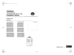
CARRYING IN THE OUTDOOR UNIT
CAUTION
Handle the outdoor unit carefully, observing the following items.
• When using a forklift or other machinery for loading/unloading in transportation, insert the prongs of the forklift
into the rectangular holes for handling as shown below.
• When lifting up the unit, insert a rope able to bear the unit’s weight into the rectangular holes for handling, and
tie the unit from 4 sides.
(Apply padding in positions where the rope comes into contact with the outdoor unit so that no damage is caused
to the outer surface of the outdoor unit.)
(There are reinforcing plates on the side surfaces, so the rope cannot be passed through.)
GOOD
NO GOOD
NO GOOD
Plaster
Rope
Rectangular
holes for
handling
Plaster
Side
Rectangular
holes for
lifting
NO GOOD
Front /Back
GOOD
Prongs of the
forklift
– 15 –
Reinforcing
plate
Weight centre and weight
Weight centre of an outdoor unit
(B)
(A)
Anchor bolt position
920
Y
Anchor bolt position
755
Y
Anchor bolt position
755
Anchor bolt position
700
X
Z
Z
X
No.
Model type
X (mm)
Y (mm)
Z (mm)
500
390
645
MAP080
(A)
MAP100
MAP120
(B)
MAP140
MAP160
605
– 16 –
350
700
Mass (kg)
H/P
242
C/O
241
329
SELECTION OF PIPE SIZE
Coupling size of brazed pipe
Connected section
External size
Internal size
G
ØF
ØC
K
(Unit: mm)
Connected section
Standard outer dia.
of connected
copper pipe
External size
Internal size
Standard outer dia.
(Allowable difference)
C
F
+0.04
-0.02
Min. depth of
insertion
K
G
Oval value
Min. thickness
of coupling
6.35
6.35 (±0.03)
6.45 (
)
7
6
0.06 or less
0.50
9.52
9.52 (±0.03)
9.62 ( +0.04
-0.02 )
8
7
0.08 or less
0.60
+0.04
-0.02
12.70
12.70 (±0.03)
12.81 (
)
9
8
0.10 or less
0.70
15.88
15.88 (±0.03)
16.00 ( +0.04
-0.02 )
9
8
0.13 or less
0.80
+0.03
-0.03
19.05
19.05 (±0.03)
19.19 (
)
11
10
0.15 or less
0.80
22.22
22.22 (±0.03)
22.36 ( +0.03
-0.03 )
11
10
0.16 or less
0.82
+0.06
-0.02
28.58
28.58 (±0.04)
28.75 (
)
13
12
0.20 or less
1.00
34.92
34.90 (±0.04)
35.11 ( +0.04
-0.04 )
14
13
0.25 or less
1.20
+0.08
-0.02
38.10
38.10 (±0.05)
38.31 (
)
15
14
0.27 or less
1.26
41.28
41.28 (±0.05)
41.50 ( +0.08
-0.02 )
15
14
0.28 or less
1.35
Screw size and tightening torque
Screw size
Tightening torque
(N•m)
Power supply terminal
M6
2.5 to 3.0
Earth screw
M8
5.5 to 6.6
M3.5
1.2 to 1.4
Communication wire terminal
– 17 –
Adding refrigerant
After finishing vacuuming, exchange the vacuum pump with a refrigerant canister and start additional charging of
refrigerant.
Calculation of additional refrigerant charge amount
Refrigerant charge amount at shipment from the factory does not include the refrigerant for pipes at the local site.
For refrigerant to be charged in pipes at the local site, calculate the amount and charge it additionally.
NOTE
If the additional refrigerant amount indicates minus as the result of calculation, use the air conditioner without
additional refrigerant.
Outdoor unit type
MAP080
MAP100
Heat pump
type
Charging amount (kg)
Cooling only
type
Outdoor unit type
MAP080
MAP100
Charging amount (kg)
10.5
10.5
Additional refrigerant charge
amount at local site
=
MAP120
MAP140
MAP160
MAP120
MAP140
MAP160
10.5
11.5
11.5
11.5
×
Real length of liquid pipe
Additional refrigerant charge
amount per 1m liquid pipe
(Table 1)
+
Corrective amount of refrigerant
depending on HP of cooperating outdoor units
(Table 2)
Table 1
Liquid pipe dia. (mm)
Additional refrigerant amount/1m liquid
pipe (kg/m)
6. 4
9 .5
1 2. 7
1 5 .9
1 9. 1
2 2. 2
0.025
0.055
0.105
0.160
0.250
0.350
– 18 –
Table 2
Combined HP (HP)
Standard type
High Efficiency type
C (Corrective amount
of refrigerant) (kg)
Combined outdoor units (HP)
8
8HP
–
–
–
1.5
10
10HP
–
–
–
2.5
12
12HP
–
–
–
3.5
14
14HP
–
–
–
8.5
16
16HP
–
–
–
10.5
18
10HP
8HP
–
–
0.0
20
10HP
10HP
–
–
3.0
22
12HP
10HP
–
–
5.0
24
12HP
12HP
–
–
7.5
26
16HP
10HP
–
–
8.5
28
16HP
12HP
–
–
9.5
30
16HP
14HP
–
–
11.5
32
16HP
16HP
–
–
12.5
34
12HP
12HP
10HP
–
3.0
36
12HP
12HP
12HP
–
4.0
38
16HP
12HP
10HP
–
6.0
40
16HP
12HP
12HP
–
7.0
42
16HP
14HP
12HP
–
8.0
44
16HP
16HP
12HP
–
10.0
46
16HP
16HP
14HP
–
12.0
48
16HP
16HP
16HP
–
14.0
16
8HP
8HP
–
–
0.0
24
8HP
8HP
8HP
–
-4.0
26
10HP
8HP
8HP
–
-4.0
28
10HP
10HP
8HP
–
-2.0
30
10HP
10HP
10HP
–
0.0
32
8HP
8HP
8HP
8HP
-6.0
34
10HP
8HP
8HP
8HP
-6.0
36
10HP
10HP
8HP
8HP
-6.0
38
10HP
10HP
10HP
8HP
-6.0
40
10HP
10HP
10HP
10HP
-5.0
42
12HP
10HP
10HP
10HP
-4.0
44
12HP
12HP
10HP
10HP
-2.0
46
12HP
12HP
12HP
10HP
0.0
48
12HP
12HP
12HP
12HP
2.0
Charging of refrigerant
• Keeping the valve of the outdoor unit closed, be sure to charge the liquid refrigerant into the service port at the
liquid side.
• If the specified amount of refrigerant cannot be charged, fully open the valves of the outdoor unit at liquid and
gas sides, operate the air conditioner in COOL mode, and then charge refrigerant into service port at the gas
side. In this time, choke the refrigerant slightly by operating the valve of the canister to charge liquid refrigerant.
• The liquid refrigerant may be charged suddenly, therefore be sure to charge refrigerant gradually.
– 19 –
New Refrigerant (R410A)
This air conditioner adopts a new HFC type refrigerant (R410A) which does not deplete the ozone layer.
1. Safety Caution Concerned to New Refrigerant
The pressure of R410A is high 1.6 times of that of the former refrigerant (R22). Accompanied with change of
refrigerant, the refrigerating oil has been also changed. Therefore, be sure that water, dust, the former refrigerant
or the former refrigerating oil is not mixed into the refrigerating cycle of the air conditioner with new refrigerant
during installation work or service work. If an incorrect work or incorrect service is performed, there is a possibility
to cause a serious accident. Use the tools and materials exclusive to R410A to purpose a safe work.
2. Cautions on Installation/Service
(1) Do not mix the other refrigerant or refrigerating oil.
For the tools exclusive to R410A, shapes of all the joints including the service port differ from those of the former
refrigerant in order to prevent mixture of them.
(2) As the use pressure of the new refrigerant is high, use material thickness of the pipe and tools which are
specified for R410A.
(3) In the installation time, use clean pipe materials and work with great attention so that water and others do not
mix in because pipes are affected by impurities such as water, oxide scales, oil, etc. Use the clean pipes.
Be sure to brazing with flowing nitrogen gas. (Never use gas other than nitrogen gas.)
(4) For the earth protection, use a vacuum pump for air purge.
(5) R410A refrigerant is azeotropic mixture type refrigerant. Therefore use liquid type to charge the refrigerant.
(If using gas for charging, composition of the refrigerant changes and then characteristics of the air conditioner
change.)
3. Pipe Materials
For the refrigerant pipes, copper pipe and joints are mainly used. It is necessary to select the most appropriate
pipes to conform to the standard. Use clean material in which impurities adhere inside of pipe or joint to a minimum.
(1) Copper pipe
<Piping>
The pipe thickness, flare finishing size, flare nut and others differ according to a refrigerant type.
When using a long copper pipe for R410A, it is recommended to select “Copper or copper-base pipe without
seam” and one with bonded oil amount 40mg/10m or less. Also do not use crushed, deformed, discolored
(especially inside) pipes. (Impurities cause clogging of expansion valves and capillary tubes.)
<Flare nut>
Use the flare nuts which are attached to the air conditioner unit.
(2) Joint
The flare joint and socket joint are used for joints of the copper pipe. The joints are rarely used for installation
of the air conditioner. However clear impurities when using them.
– 20 –
4. Tools
(1) Required Tools for R410A
Mixing of different types of oil may cause a trouble such as generation of sludge, clogging of capillary, etc.
Accordingly, the tools to be used are classified into the following three types.
1) Tools exclusive for R410A (Those which cannot be used for conventional refrigerant (R22))
2) Tools exclusive for R410A, but can be also used for conventional refrigerant (R22)
3) Tools commonly used for R410A and for conventional refrigerant (R22)
The table below shows the tools exclusive for R410A and their interchangeability.
Tools exclusive for R410A (The following tools for R410A are required.)
Explanation of symbols
: Newly prepared (It is necessary to use it exclusively with R410A, separately from those for R22 or R407C.)
: Former tool is available.
Used tools
Usage
Gauge manifold
Proper use of tools/parts
Charging hose
Vacuuming, charging refrigerant
and operation check
Charging cylinder
Charging refrigerant
Gas leak detector
Checking gas leak
Exclusive to R410A
Exclusive to R410A
Unusable (Use the Refrigerant charging balance.)
Exclusive to R410A
Vacuum pump
Vacuum drying
Vacuum pump with counterflow
Vacuum drying
Usable if a counter-flow preventive adapter is attached
R22 (Existing article)
Flare tool
Flare processing of pipes
Usable by adjusting size
Bender
Bending processing of pipes
R22 (Existing article)
Refrigerant recovery device
Recovering refrigerant
Exclusive to R410A
Torque wrench
Tightening flare nut
Exclusive to Ø12.7mm and Ø15.9mm
Pipe cutter
Cutting pipes
R22 (Existing article)
Refrigerant canister
Charging refrigerant
Exclusive to R410A
Enter the refrigerate name for identification
Welding machine/Nitrogen gas
cylinder
Welding of pipes
R22 (Existing article)
Refrigerant charging balance
Charging refrigerant
R22 (Existing article)
(Note 1) When flaring is carried out for R410A using the conventional flare tools, adjustment of projection
margin is necessary. For this adjustment, a copper pipe gauge, etc. are necessary.
(Note 2) Charging cylinder for R410A is being currently developed.
General tools (Conventional tools can be used.)
In addition to the above exclusive tools, the following equipments which serve also for R22 are necessary as
the general tools.
(7) Screwdriver (+, –)
(1) Vacuum pump
(8) Spanner or Monkey wrench
Use vacuum pump by attaching vacuum pump
adapter.
(9) Hole core drill
(2) Torque wrench
(10)Hexagon wrench (Opposite side 4mm)
(3) Pipe cutter
(11)Tape measure
(4) Reamer
(12)Metal saw
(5) Pipe bender
(6) Level vial
Also prepare the following equipments for other installation method and run check.
(1) Clamp meter
(3) Insulation resistance tester
(2) Thermometer
(4) Electroscope
– 21 –
1
Wiring Diagrams
1-1. Outdoor Unit
Models: MMY-MAP0804*, MAP1004*, and MAP1204*
– 22 –
Models: MMY-MAP1404* and MAP1604*
– 23 –
1-2. Indoor Unit
1-2-1. 4-way Cassette Type
Models: MMU-AP0094HP*, AP0124HP*, AP0154HP*, AP0184HP*, AP0244HP*, AP0274HP*, AP0304HP*,
AP0364HP*, AP0484HP*, and AP0564HP*
– 24 –
1-2-2. Compact 4-way Cassette Type
Models: MMU-AP0074MH∗, AP0094MH∗, AP0124MH∗, AP0154MH∗, and AP0184MH∗
PMV
6 4 3 1 2 5
6 4 3 1 2 5
TC1
1 2 3 4 5 6
1 2 3 4 5 6
1
3
1 2 3
1
3
1 2 3
CN82 (BLU)
CN100
(BRW)
CN34
(RED)
CN333
(WHI)
5 5
TA
FS
1 2
1 2
TCJ
1 2
1 2
TC2
1 2
1 2
CN309
(YEL)
3
1
CN41
(BLU)
BLK
3 3
2
BLK
1 1
CN104 CN102 CN101
(YEL) (RED) (BLK)
Motor
drive circuit
3 3
CN40
(BLU)
1 1
5 2
2
5 1
1
CN334
(WHI)
5 5
4 4
3
2
1 1
U1 U2
CN68
(BLU)
1 1
CN71
1
(CHK)
2
CN72
1
(DISP)
2
WHI
CN80
(GRN)
RY303
3
3 3
Fuse
T3.15A
250V ~
Fuse
T6.3A
250V ~
CN73
DC20V (RED)
DC15V
DC12V CN70
DC 7 V (WHI)
Power
supply
circuit
P301
BLK
Indoor unit
earth screw
Flow selector
unit earth screw
R(L) S(N)
Power supply
single phase
220-240V, 50Hz
220V, 60Hz
1
2
CN66
(WHI)
1
2
CN44
(BRW)
1
2
3
4
5
1 2
T10 1 2 3 4 5 6
(Fan drive)
Symbol
FM
TA
TC1
TCJ
TC2
LM1, LM2
DP
FS
RY302
PMV
CN33
(WHI)
1
2
3
4
5
Parts name
Fan motor
Indoor temp. sensor
Temp. sensor
Temp. sensor
Temp. sensor
Louver motor
Drain pump motor
Float switch
Drain control relay
Pulse motor valve
CN60
(WHI)
CN81
(BLK)
1 2 3 4 5 6
1 2 3 4 5
CN61
(YEL)
Option
2
Filter
1
CN20
(BLU)
Control P.C. board
for Indoor unit
MCC-1402
Adapter for
Wireed
wireless
remote controller
remote controller
2
EXCT
1
5
4
3 GRL
2
1
CN50
(WHI)
CN32
(WHI)
3
2 PNL
1
1
2
3
4
5
1
2
3
4
5
1
2
3
4
5
1
2
3
4
5
1
2
3
4
5
1
2
3
4
5
1
2
3
4
5
LM2
LM1
Color
indication
RED : RED
WHI : WHITE
YEL : YELLOW
BLU : BLUE
BLK : BLACK
GRY : GRAY
PNK : PINK
ORN : ORANGE
BRW: BROWN
GRN : GREEN
1.
indicates the terminal bolock letter.
Letter at inside indicates the terminal number.
2. A dotted line and broken line indicate the wiring at site
3.
indicates a control P.C. board.
– 25 –
BLK
1 2
1 2
CN001
(WHI)
Outdoor
unit
1
CN67
(BLK)
RED
1 1
B
U1 U2
3 3
CN304
(GRY)
A
WHI
RY302
DP
BLU
BLU
RED : RED
WHI : WHITE
YEL : YELLOW
BLU : BLUE
BLK : BLACK
GRY : GRAY
PNK : PINK
ORN : ORANGE
BRW : BROWN
GRN : GREEN
Color
indication
WHI
RED
Power supply
Single phase
220-240V 50Hz
220V 60Hz
Indoor unit
Earth screw R(L) S(N)
RED
WHI
1 1
3
CN304
(GRY) 2
1
Heater
CN301
(BLK)
BLU
RY004
Line Filter
TR
BLU
1 2
1 2
Outdoor
unit
U1 U2
1 2
1 2
CN1
(WHI)
AI-NET
central control
terminal
A B X Y
1 2 3
1
3
Remote controller
U1 U2
BLU
1 2
1 2
YEL
BLU
ORN
BLK
RED
L
CN03
(RED)
1 1
2 2
3 2 1 CN02
3 2 1 (BLU)
Network
adaptor
P.C. board
Network
CN01 1 2 adaptor
(WHI) 1 2 (Option)
1 2 3 4 5
RY005
RY006
M
CN050
(WHI)
H
MCC-1401
RY007
DP
2 1
2 1
LM
LM
2 1
2 1
FS
FS
TR
1 2 3 4 5 6 CN01
1 2 3 4 5 6 (WHI)
Sub P.C. board
MCC-1520
1 2 3 4 5 6 CN02
1 2 3 4 5 6 (YEL)
1 2 3 4 5 6
1 2 3 4 5 6
CN075
(WHI)
1 2 3 4 5 6
CN061
(YEL)
3.
indicates the control P.C. board.
2. A dotted line and broken line indicate the wiring at site.
indicates the terminal number.
PMV
PMV
CN060
(WHI)
Symbol
FM
RC
TR
LM
TA
TC1,TCJ
RY001
RY002
RY004
RY005~007
FS
DM
PMV
TA
1
2
3
4
5
1 1
Filter
2 2
TC1
TCJ
1 EXCT
2
Parts name
Fan motor
Running capacitor
Power transformer
Louver motor
Indoor temp sensor
Temp sensor
Flap motor control relay
Drain pump control relay
Heater control relay
Fan motor control relay
Float switch
Drain pump motor
Pulse Motor Valve
Option
1 2 3 4 5 6
Fan drive
1 2
CN032
(WHI)
CN081
(BLK)
CN070
(WHI)
CN073
(RED)
CN080
(GRN)
1
2 PNL
3
1 1
2 2
3 3
1
2
CN101
(BLK)
CN100
(BRW)
1 1
2 2
1 1
2 2
CN102
(RED)
CN104
(YEL)
1 2 3 4 5 6 (BLU)
1 2 3 4 5 6 CN082
6 4 3 1 2 5
6 4 3 1 2 5
Indoor control P.C. board
indicates the terminal block, letter at inside
1 2 3
1 2 3
Power supply
circuit
RY001
1 2 3 (BLU) 1 2 3 (GRN) 1 2 3 (RED)
1 2 3 CN068 1 2 3 CN033 1 2 3 CN030
CN074
(WHI)
1.
DM
1 2 3
1 2 3
RY002
UL
FAN
9 8 7 6 5 4 3 2 1
CN083(WHI) 9 8 7 6 5 4 3 2 1
CN044 CN040 CN041
(BRW) (BLU) (BLU)
1 1
2 2 CN067 Fuse
(BLK) T5.0A
3 3
CN066 1
(WHI) 2
AC IN
3 3
CN309
(YEL) 2 2
Closed end
connector
Flow selector
unit earth
screw
RC
BLU
FM
BLK
1
2
3
4
5
6
BLU
– 26 –
BLK
1
2
3
4
5
6
1-2-3. 1-way Cassette Type (Compact type)
Models: MMU-AP0074YH∗, AP0094YH∗, and AP0124YH∗
– 27 –
R(L) S(N)
Outdoor
unit
U1 U2
Wired
remote
controller
A B
BLK
WHI
BLK
Adapter for
wireless remote
controller
1 2
1 2
CN001(WHI)
WHI
Parts name
Fan motor
Indoor temp sensor
Temp sensor
Temp sensor
Temp sensor
Louver motor
Drain pump motor
Float switsh
Drain control relay
Pulse motor valve
Transformer
U1 U2 A B
WHI Closed-end
connector
RED
Power supply
single phase
220-240V 50Hz
220V 60Hz
Indoor unit
earth screw
Symbol
Flow selector unit
earth screw
FM
TA
TC1
TCJ
TC2
LM
DP
FS
RY302
PMV
TR
Color
indication
X Y
1 2
1 2
Network adapter
(Option)
AI-NET
1 2
1 2
WHI
RED
CN01
CN02 (WHI)
(BLU) CN03
(RED)
MCC-1401
1 1
2
3 3
TR
RED: RED
WHI : WHITE
YEL : YELLOW
BLU : BLUE
BLK : BLACK
GRY: GRAY
PNK : PINK
ORN: ORANGE
BRN: BRWN
GRN: GREEN
DP
BLK
BLK
BLU
BLU
CN67
(BLK)
3
1
1 1
2
3 3
1 2
1 2
1
2
BLK
3 3
1 1
CN304
(GRY)
3 3
CN68
(BLU)
1 1
CN41
(BLU)
CN40
(BLU)
CN66
(WHI)
P301
1
1
Fuse
T6.3A 250V~
RY303
RY302
3
3
CN309
(YEL)
CN334 5 4
1
(WHI) 5 4 3 2 1
3
3
T10
1 2 3 4 5 6
1 2
Fan
drive
CN32
(WHI)
Fuse
T3.15A
250V~
1 2 3 4 5 6 CN82
1 2 3 4 5 6 (BLU)
Option
1 2 3 4 5 6
CN60
(WHI)
1 2 3 4 5
CN20
(BLU)
GRL
1 2 3 4 5
(DISP)
(CHK)
1 2 3 4 5 CN33
1 2 3 4 5 (WHI)
CN72
CN81
(BLK)
LM
1 2 3 4 5
1 2 3 4 5
CN71
CN110
(WHI)
1 2
Control P.C. board
for indoor unit
MCC-1402
Power
supply
circuit
CN111
(WHI)
CN112
(WHI)
DC20V
DC15V
DC12V
DC7V
1 2
1 2
1 2
High ceiling setup
indicates the terminal bolock letter.
Letter at inside indicates the terminal number.
2. A dotted line and broken line indicate the wiring at side
3.
indicates a control P.C. board.
1.
1 2 3 4 5
CN50
(WHI)
PMV
6 4 3 1 2 5
6 4 3 1 2 5
CN061
(YEL)
5 CN333
5 (WHI)
Motor drive
circuit
1
1
FM
CN70
(WHI)
CN73
(RED)
CN80
(GRN)
CN100
(BRW)
CN101
(BLK)
CN102
(RED)
CN104
(YEL)
1
3
1 2 3
TC2
TCJ
TA
1
2
Filter
1
EXCT
2
1
2 PNL
3
3 3
1 1
1 1
2 2
1 1
2 2
1 1
2 2
CN34
(RED)
FS
TC1
1-2-4. 1-way Cassette Type SH series
Models: MMU-AP0154SH∗, AP0184SH∗, and AP0244SH∗
1-2-5. 2-way Cassette Type 2 series
Models: MMU-AP0072WH, AP0092WH, AP0122WH, AP0152WH, AP0182WH, AP0242WH,
AP0272WH, AP0302WH, AP0482WH
– 28 –
R(L) S(N)
Outdoor unit
U1 U2
1
1 1
2 2
3 3
1 1
CN44 1
(BRW) 2
BLK
Adaputor for wired
remote controller
Wired remote
controller
CN001
(WHI)
1 1
3
3
1 2 3
1 2 3
CN50
(WHI)
5
5
FM
X Y
1 2 CN03
1 2 (RED)
Network
adaptor
P.C. board
Network
CN01 1 2 adaptor
(WHI) 1 2 (Option)
3 3
2 2
1 1
CN61
(YEL)
Power
supply
circuit
indicates the terminal number.
indicates the terminal block, letter at inside
(Signal output)
3.
indicates the control P.C. board.
1 1
2 2
CN101
(BLK)
: BLACK
: GRAY
: PINK
: ORANGE
: GREEN
Parts name
Fan motor
Indoor temp sensor
Indoor temp sensor
Drain pump motor
Float switch
Drain pump control relay
Pulse Motor Valve
BLK
GRY
PNK
ORN
GRN
Color identification
1
2
1 EXCT
2
CN73
(RED)
TC1
TC2
CN80
(GRN)
CN20 CN70
(BLU) (WHI)
TA
TCJ
1
2 PNL
3
1 1
2 2
3 3
1 1
2 2
CN102
(RED)
CN100
(BRN)
1 1
2 2
CN104
(YEL)
1 2 3 4 5
Symbol
FM
TA
TC1,TC2,TCJ
DM
FS
RY302
PMV
FS
1 CN34
3
3 2 1 (RED)
RED : RED
WHI : WHITE
YEL : YELLOW
BLU : BLUE
BRW : BROWN
1 2 3 4 5
CN81
(BLK)
2. A dotted line and broken line indicate the wiring at site.
1.
1 2 3 4 5 6
CN60
(WHI)
1 2
CN32
(WHI)
(Fan drive)
DC20V
DC15V
DC12V
DC7V
CN33
1 2 3 4 5 (WHI)
Indoor control P.C. board
1 2 3 4 5 6 CN82
1 2 3 4 5 6 (BLU)
6 4 3 1 2 5
6 4 3 1 2 5
PMV
T10 1 2 3 4 5 6
250V~
Fuse
T3.15A
1 2 3 4 5
CN02
(BLU)
TR
1 2 3
1 2 3
–
+
Motor drive
circuit
CN333 1
(WHI) 1
CN309
(YEL)
~
~
1 2
1 2
WHI
WHI
BLK
1 2 3
1 2 3
CN41
(BLU)
CN334
(WHI)
1 2
1 2
CN40
(BLU)
P301
250V~
Fuse
T6.3A
RY302
5 4
2 1
5 4 3 2 1
1 2
1 2
CN1
(WHI)
BLK
A B
WHI
U1 U2
BLK
3 3
CN66 1
(WHI) 2
WHI
CN67
(BLK) 2 2
RED
3
CN304
(GRY) 2
Flow selector
unit earth
screw
Closed end
connector
WHI
Reactor
WHI
Indoor unit power supply
Single phase
220-240V 50Hz
220V 60Hz
Earth screw
Indoor unit
RED
1
3
1 2 2
DM
CN68
(BLU)
BLU
BLU
BLK
– 29 –
BLK
5 5
4 4
1-2-6. Concealed Duct Standard Type
Models: MMD-AP0074BH∗, AP0094BH∗, AP0124BH∗, AP0154BH∗, AP0184BH∗, AP0244BH∗,
AP0274BH∗, AP0304BH∗, AP0364BH∗, AP0484BH∗, and AP0564BH∗
1-2-7. Concealed Duct Standard Type 6 series
Models : MMD-AP0076BH∗, AP0096BH∗, AP0126BH∗, AP0156BH∗, AP0186BH∗, AP0246BH∗,
AP0276BH∗, AP0306BH∗, AP0366BH∗, AP0486BH∗, AP0566BH∗
– 30 –
Indoor unit
Earth screw
Closed
end
connector
WHI
RED
S(N)
F
CN067
(BLK)
RY007
1 2
1 2
4
43F1
3
5
43F1
1 2 3 4
1 2 3 4 GRY
FM
Remote controller
1 2
1 2
CN1
(WHI)
A B
1 2 3
1
3
RC
U1 U2
OC
U1 U2
EMG
1 2
CN044 CN040 CN041
(BRW) (BLU) (BLU)
Outdoor unit
YEL
Closed end
connector
Fuse
T5.0A
CN066
(WHI)
RED
RED 6
Flow selector
unit earth
screw
TR
1
2
1 1
2 2
3 3
RED
RC
L
3 3
2
1 1
F4
F3
F2
X Y
F1
WHI
MCC-1401
Network adaptor
(Option)
1 2 CN03
1 2 (RED)
CN01 1 2
(WHI) 1 2
DP
LM
1 2 3
1 2 3
1 2
1 2
CN075 CN061
(WHI) (YEL)
CN032
(WHI)
CN060
(WHI)
CN082
(BLU)
CN081
(BLK)
TR
1 2 3 4 5 6 CN01
1 2 3 4 5 6 (WHI)
Sub P.C. board
MCC-1520
1 2 3 4 5 6 CN02
1 2 3 4 5 6 (YEL)
Motor over heating protection switch
WHI
GRY
RED
BLK
Wired for MMD-AP0481 only
(BRN Wire)
49F
BLU
ORN
BRN
6
5
4
3
2
1
Symbol
FM
RC
TR
TA
TC1,TC2,TCJ
RY005~007
RY001
RY002
PMV
F
43F1
Sold
DM
separately
FS
6
5
4
3
2
1
1
2
3
4
5
5
2
1
3
4
6
5
2
1
3
4
6
PMV
Parts name
Fan motor
Running capacitor
Transformer
Indoor temp sensor
Temp sensor
Fan motor control relay
Flap motor control relay
Drain control relay
Pulse Motor Valve
Fuse
Fan motor control relay
Drain pump motor
Float switch
1
Filter
2
1 EXCT
2
CN073
(RED)
CN070
(WHI)
1
2 PNL
3
CN080
(GRN)
1 2 3 CN100
1 2 3 (BRN)
TC1
1 2 3 4 5 6 1 2 3 4 5 6 1 2 1 2 3 4 5 6
Option
1 2 3 4 5 6 T10
Fan drive
Power
supply
circuit
1 2
1 2
TC2
CN104 CN102 CN101
(YEL) (RED) (BLK)
1 2
1 2
TCJ
Indoor control P.C. board
FS
CN030
(RED)
1 2 3
1 2 3
TA
1.
indicates the terminal block, letter at inside indicates the terminal number.
2. A dotted line and broken line indicate the wiring at site.
3.
indicates the control P.C. board.
4. When attaching a drain pump, exchange CN030 connector with a connector
of the float switch.
5. A part is connected to the terminal block.
When exchanging to the outside static pressure necessary at the local site,
check the terminal No. and lead color of the fan motor in the below diagram,
and then exchange the lead wire indicated by the arrow mark (
),
6. Pay attention to change static pressure because the outside static pressure of
H tap in 50 or 60Hz.
CN074
(WHI)
RY001
1 2 3 (BLU) 1 2 3 (GRN)
1 2 3 CN068 1 2 3 CN033
RY002
UL
1 2 3 4 5
CN050
(WHI)
RY005
RY006
M
CN02
(BLU)
H
FAN
9 8 7 6
4
2
CN083(WHI) 9 8 7 6 5 4 3 2 1
7
RY004
P301
43F1
1 1
CN309
2 2 (YEL)
3 3
3
CN304
(GRY) 2
1
(BLK)
T10A,250V~
Power supply
Single phase
220-240V 50Hz
220V 60Hz
R(L)
RED
RED : RED
WHI : WHITE
YEL : YELLOW
BLU : BLUE
BLK : BLACK
GRY : GRAY
PNK : PINK
ORN : ORANGE
BRW : BROWN
GRN : GREEN
8
BLU
WHI
DP
(Option)
ORN
Color
indication
WHI
RED
GRY
WHI
RED
BLK
– 31 –
BRN
Spark
killer
1-2-8. Concealed Duct High Static Pressure Type
Models: MMD-AP0184H∗, AP0244H∗, AP0274H∗, AP0364H∗, and AP0484H∗
BLK
49F
FM
RC
TR
TA
TC1,TC2,TC3
RY005~007
RY001
RY002
PMV
F1~3
43F1,43F2
DM
FS
Symbol
RED : RED
WHI : WHITE
YEL : YELLOW
BLU : BLUE
BLK : BLACK
GRY : GRAY
PNK : PINK
ORN : ORANGE
BRW : BROWN
GRN : GREEN
RED
WHI
WHI
R(L) S(N)
RED
Parts name
Fan motor
Running capacitor
Transformer
Indoor temp sensor
Temp sensor
Fan motor control relay
Louver control relay
Drain control relay
Pulse motor valve
Fuse for fan motor
Fan motor control relay
Drain pump motor
Float switch
Power supply
single phase
220-240V 50Hz
220V 60Hz
Indoor unit
earth screw
Closed-end
connector
Motor over heating
protection switch
Color
indication
WHI
GRY
RED
YEL
BLU
ORN
43F2
WHI
RED
8
AC IN
S.K
RED
F3
F2
3
5
B
FAN3
1 2 3 4 4P
1 2 3 4 (RED)
5
RED
FM3
RC
F1
ORW
F2
F3
X Y
F4
CN03(RED)
1 2
1 2
CN074 1
(WHI) 1
4
6
43F2
MCC-1401
FAN2
1 2 3 4 4P
1 2 3 4 (BLU)
3
3
FM2
F1
ORW
RC
LM
CN033
3 (GRN)
Indicates the terminal bolock, letter.
Letter at inside indicates the terminal number.
2. A dotted line and bro ken line indicate
the wiring at side.
3.
indicate the control p.c. board.
4. When installing the drain pump connector
the froat switch connector to CN030 connector.
1.
Closed-end
connector
3
43F1
A
RY001
DP
3 CN068
3 (BLU) 1
Network Adapter
(Option)
CN01(WHI)
CN02
(BLU)
1 2
1 2
1 2 3 4 5
3 3
2
1 1
1
1
RY002
UL
1
1
CN050
(WHI)
RY005
L
3
3
RY006
M
H
1 2
1 2
CN1
Remote Controller
RED
43F2
Outdoor unit
U1 U2
T10.0A, 250V~
5
CN041
(BLU)
RY007
5
5
7
7
1 2
1 2 3
1 2 CO 1
3 RC
U1 U2
Line Filter
1 2
EMG
TR
CN044 CN040
(BRW) (BLU)
CN066
(WHI)
CN067
(BLK)
T5.0A 250V~
FUSE
(YEL)
CN309
(GRY)
CN304
RY004
T10.0A, 250V~
T10.0A, 250V~
RED
RED
1
2
3 3
F1
WHI
1 1
3 3
1 1
3
1
P301
(BLK)
RED
Sold separately
7
8
WHI
43F1
8
S.K
WHI
WHI
FAN
CN083 9
(WHI) 9
BLK
Fan motor inside
wiring diagram
BLU
WHI
RED
GRY
YEL
BLU
WHI
RED
GRY
BLK
Spark Killer
YEL
7
BLU
7
ORN
WHI
RED
GRY
WHI
RED
GRY
RED
F2
F3
F4
1 2 3 4 5 6 CN01
1 2 3 4 5 6 (YEL)
TR
CN061
(YEL)
4
6
43F1
1 2 3 4 5 6
1 2 3 4 5 6 CN02
1 2 3 4 5 6 (YEL)
Sub P.C. board
MCC-1520
1 2
1 2
1 2
1 2
TC2
CN104 CN102 CN101
(YEL) (RED) (BLK)
1 2
1 2
TCJ
FAN1
1 2 3 4 4P
1 2 3 4 (WHI)
6
5
4
3
2
1
CN082
(BLU)
OPTION
6
5
4
3
2
1
5
2
1
3
4
6
5
2
1
3
4
6
PMV
FM1
F1
ORW
RC
F2
F3
F4
Terminal Fan motor Static pressure
Note
No.
wiring
Pa (mmAg)
69(7)
F1
YEL
BLU
F2
137(14)
Setting from factory
ORN
F3
196(20)
1 2 3 4 5 6
1 2
CN060
(WHI)
1
2
3
4
5
1
FILTER
2
1
EXCT
2
1
2 PNL
3
CN081
(BLK)
CN070
(WHI)
CN073
(RED)
CN100
(BRW) CN080
(GRN)
1
3
1 2 3
TC1
FAN
DRIVE
CN032
(WHI)
Control P.C. board
for Indoor unit
MCC-1403
CN075
(WHI)
1 2 3 4 5 6
1 2 3 4 5 6
Power supply
circuit
3
3
CN030
(RED)
FS
1
1
TA
A Position is connected to terminal block when change to
static pressure. Exchange the lead wire of arrow
position after check the terminal number as figure
and lead wire's color of fan motor.
6. When midifiy the high tap, to care the static pressure are
differ by 50Hz or 60Hz.
5.
YEL
DM
BLU
(Option)
ORN
WHI
RED
GRY
WHI
RED
GRY
RED
YEL
6
BLU
– 32 –
ORN
RED
Models: MMD-AP0724H ∗ and AP0964H ∗
: RED
: WHITE
: YELLOW
: BLUE
: BLACK
: GRAY
: PINK
: ORANGE
: BRWN
: GREEN
Indoor unit
Earth screw
Flow
Selector unit
Earth screw
Closed-end
connector
RED
WHI
YEL
BLU
BLK
GRY
PNK
ORN
BRN
GRN
R(L) S(N)
Outdoor unit
1
2
BLK
3 3
1 1
3
1
3 3
B
1 2
1 2
CN40
(BLU)
CN66
(WHI)
P301
CN67
(BLK)
Fuse
T6.3A
250V~
CN304
(GRY)
B
FM
1 2 3
1
3
CN41
(BLU)
1
5 4
1 CN334
5 4 3 2 1 (WHI)
RY302
Wired remote
controller
A
A
CN44 1
(BRW) 2
WHI
RED
U1 U2
U1 U2
Power supply
220-240V~, 50Hz
220V~, 60Hz
RED
WHI
DM
CN68
(BLU)
1 1
Drain pump type
("SPH" Type)
3
1
CN68
(BLU)
BLU
Color
indication
BLU
BLK
– 33 –
BLK
Non Drain pump type
("SH" Type)
3
3
3
1 2 3 4 5
CN50
(WHI)
1 2 3 4 5 6
CN61
(YEL)
DC20V
DC15V
DC12V
DC7V
1 2
Fan drive
CN32
(WHI)
CN111
(WHI)
1 2
CN110
(WHI)
1 2
CN72
CN71
Symbol
FM
TA
TC1,TC2,TCJ
RY302
PMV
DM
FS
1 2 3 4 5 6
Option
CN60
(WHI)
CN20
(BLU)
1
EXCT
2
1
2
CN80
(GRN)
CN73
(RED)
CN70
(WHI)
TC2
TCJ
TA
1
2 PNL
3
3 3
1 1
1 1
2 2
CN101
(BLK)
CN100
(BRW)
1 1
2 2
1 1
2 2
CN34
(RED)
CN102
(RED)
CN104
(YEL)
1
3
1 2 3
FS
Drain pump type
("SPH" Type)
1 2 3 4 5
CN34
(RED)
Parts name
Fan motor
Indoor temp sensor
Temp sensor
Drain control relay
Pulse motor valve
Drain pump motor
Float switch
1 2 3 4 5
CN81
(BLK)
(DISP)
(CHK)
1 2 3 4 5 (WHI)
CN33
1
3
1 2 3
Non Drain pump type
("SH" Type)
Control P.C. board
for undoor unit
MCC-1402
indicates the terminal bolock.
Letter at inside indicates the terminal number.
2. A dotted line and broken line indicate the
wiring at side
3.
indicate a control P.C. board.
1.
CN309
(YEL)
Power
supply
circuit
CN112
(WHI)
1 2
1 2
(External static pressure setup)
1 2 3 4 5 6 CN82
1 2 3 4 5 6 (BLU)
Fuse
T3.15A
250V~
5 CN333
5 (WHI)
Motor drive
circuit
1
1
6 4 3 1 2 5
6 4 3 1 2 5
PMV
TC1
1-2-9. Slim Duct Type
Models: MMD-AP0074SPH∗, AP0094SPH∗, AP0124SPH∗, AP0154SPH∗, and AP0184SPH∗
1-2-10. Slim Duct Type (AP024, AP027)
Models: MMD-AP0244SPH∗, MMD-AP0274SPH∗
– 34 –
RED
– 35 –
Flow selector
unit earth
screw
DM
3
CN304 1
(GRY) 2
1 1
2 2
3 3
CN68
(BLU)
CN41
(BLU)
CN40
(BLU)
CN66
(WHI)
Fuse
T6.3A
250V~
P301
RY303
RY302
BLK
–
Adpter for wireless
remote controller
CN001
(WHI)
BLK
WHI
BLK
1 2 3 4 5
3 3
2 2
1 1
indicates the terminal block, letter at inside
indicates the terminal number.
3.
indicates the control P.C. board.
Sold
separately
1 2 3 4 5
1 2 3 4 5 6
Option
CN81
(BLK)
CN60
(WHI)
DC20V
DC15V
DC12V
DC7V
2. A dotted line and broken line indicate the wiring at site.
1.
X Y
1 2 CN03
1 2 (RED)
Network
adaptor
P.C. board
Network
CN01 1 2 adaptor
(WHI) 1 2 (Option)
CN02
(BLU)
TR
1 2
Fandrive
CN32
(WHI)
Power
supply
circuit
T10
CN61
(YEL)
Fuse
T3.15A
Indoor control P.C. board
CN70
(WHI)
CN73
(RED)
CN80
(GRN)
CN100
(BRW)
BLK
GRY
PNK
ORN
GRN
: BLACK
: GRAY
: PINK
: ORANGE
: GREEN
TC1
TC2
1 FILTER
2
Parts name
Fan motor
Indoor temp sensor
Temp sensor
Louver motor
Drain control relay
Drain pump motor
Float switch
RED : RED
WHI : WHITE
YEL : YELLOW
BLU : BLUE
BRW : BROWN
TA
TCJ
1 EXCT
2
1
2 PNL
3
1 1
2 2
3 3
1 1
2 2
1 1
2 2
CN102
(RED)
CN101
(BLK)
1 1
2 2
CN104
(YEL)
Color identification
GR L
FS
3 CN34
1
1 2 3 (RED)
1 2 3 4 5
CN20
(BLU)
Symbol
FM
TA
TC,TC2,TCJ
LM
RY302
DM
FS
1 2 3 4 5 CN33
1 2 3 4 5 (WHI)
1 2 3 4 5 6 CN82
1 2 3 4 5 6 (BLU)
LM
1 2 3 4 5
1 2 3 4 5
6 4 3 1 2 5
6 4 3 1 2 5
1 2 3 4 5 6
Motor drive
circuit
+
CN50
(WHI)
Wired remote
controller
WHI
1 2 3
1 2 3
CN309
(YEL)
~
~
1 2
1 2
CN1
(WHI)
FM
1 CN334 1 2 3 4 5 CN333
5 4
5 4 3 2 1 (WHI) 1 2 3 4 5 (WHI)
1 2
1 2
WHI
U1 U2 A B
1 1
2
BLK
3 3
BLK
2 2
BLU
1 1
BLU
1
2
BLK
1 1
CN67
(BLK) 2 2
3 3
Outdoor unit
U1 U2
Closed end
terminal
RED
WHI
Power supply
single phase
200-240V 50Hz
200V 60Hz
R(L) S(N)
Earth screw
Indoor unit
WHI
PMV
1-2-11. Ceiling Type
Models: MMC-AP0154H∗, AP0184H∗, AP0244H∗, AP0274H∗, AP0364H∗, and AP0484H∗
Power Supply
Single phase
220-240V 50Hz
220V 60Hz
1 1
3
3
1 2 3 4 5
1 2 3 4 5
1 2 3 4 5
CN81 (BLK)
F301 Fuse
T3. 15A 250V~
Flow selector Unit
(Sold sepalately)
CN309 1
(YEL) 1
GRN & YEL
5
CN67
(BLK)
WHI 3 3
RED
:
GRN
WHI
GRN & YEL
BROWN
RED
WHITE
YELLOW
BLUE
BLACK
GRAY
PINK
ORANGE
GREEN &
YELLOW
GREEN
WHI
BRW
YEL
GRY
PNK
Heat exchanger
GRN & YEL
:
:
:
:
:
:
:
:
:
:
RED
BRW
RED
WHI
YEL
BLU
BLK
GRY
PNK
ORN
GRN & YEL
HBS
CN50
(WHI)
1 2 3 4 5
CN213 (WHI)
F
Pulse motor
valve
1 2 3 4 5 6 7 8 9 10
1 2 3 4
7 8 9 10
CN22
S
BLK
Infrared rays receive
and indication parts
(MCC-861)
9
7 6 5 4 3 2
11 10 9 8 7 6 5 4 3 2 1
WHI
BRW
YEL
– 36 –
GRY
ORN
RED
BLU
RED
BRW
BLU
ORN
YEL
WHI
BLU
YEL
WHI
BLK
CN210
(WHI)
6 5 4 3
6 5 4 3
1
1
RED
5 4 3 2 1
Power
supply
circuit
CN33
(WHI)
6 5 4 3 2
6 5 4 3 2 1
DC 7V
1 2 3 4
HA
1 2 3 4 5 6
1 2 3 4 5 6
1 2
Fan Drive
CN61
(YEL)
CN32
(WHI)
Option
1 2 3 4 5 6
CN60
(WHI)
1 2 3
PNL/EMG
BLK
1 1
BLK
2 2
BLK
1 1
BLK
2 2
CN102
(YEL)
CN104
CN80 (WHI)
(GRN)
1
2
TF
BLK
1 1
2 2 BLK
BLK
1 1
2
BLK
3 3
BLK
3 3
2
WHI
1 1
BLU
1 1
2 2 BLU
CN103
(GRN)
CN101
(BLU)
(BRW)
DC 0V
CN100
DC 12V
DC 15V
CN41
(BLU)
CN44 CN40
(BRW) (BLU)
1 2
Thermo
sensor
(TA)
Heat
exchanger
sensor
(TCJ)
Heat
exchanger
sensor
(TC2)
Heat
exchanger
sensor
(TC1)
1 2
1 2
BLK
Wierd remote
controller
(Sold Separately)
CN1(WHI)
WHI
Outdoor unit
indicates the terminal block.
Letter at inside indicates the terminal number.
2. A dotted line and broken line indicate the
wiring at site.
3.
indicates the control P.C.board
1.
(MCC-1510)
Control P.C.board for indoor unit
CN82
(BLU)
6 5 4 3 2 1
6 5 4 3 2 1
Fan
motor
Louver
motor
YEL
YEL
YEL
YEL
WHI
Color identification
1-2-12. High Wall Type 4MH series
Models: MMK-AP0074MH∗, AP0094MH ∗, and AP0124MH ∗
1-2-13. High Wall Type 3 series
Models: MMK-AP0073H, AP0093H, AP0123H, AP0153H, AP0183H, AP0243H
– 37 –
TR
CN066
(WHI)
1 1
2 2
RED
Closed-end
connector
WHI
Power supply
single phase
220-240V 50Hz
220V 60Hz
R(L) S(N)
Indoor unit
earth screw
1 1
3 3
WHI
CN067
(BLK)
RED
3 3
1 1
3 3
1 1
P301
(BLK)
FUSE
(YEL)
CN309
(GRY)
CN304
1 2
1 2
CN040
(BLU)
Outdoor unit
U1 U2
U1 U2
B
1 2
1 2
CN1
A
3 3
2
1 1
H
L
X Y
1 2
1 2
CN03(RED)
CN02
(BLU)
MCC-1401
3
3
3
LM
1
1 2 3 4 5 6
1 2 3 4 5 6
Sub P.C. board
MCC-1520
1 2 3 4 5 6
1 2 3 4 5 6
CN01
(WHI)
CN02
(YEL)
TR
CN061
(YEL)
1 2 3 4 5 6
T10
CN075
(WHI)
1 2 3 4 5 6
1 2 3 4 5 6
PMV
1 2 3 4 5 6 CN082
1 2 3 4 5 6 (BLU)
1
2
3
4
5
CN081
(BLK)
OPTION
Symbol
FM
RC
TR
TA
TC1,TC2,TCJ
RY001
RY002
RY004
RY005~007
PMV
1 2 3 4 5 6
1 2
CN060
(WHI)
1
2
CN070
(WHI)
RED : RED
WHI : WHITE
YEL : YELLOW
BLU : BLUE
BLK : BLACK
GRY : GRAY
PNK : PINK
ORN : ORANGE
BRW : BROWN
GRN : GREEN
Color
indication
Parts name
Fan motor
Running capacitor
Transformer
Indoor temp sensor
Temp sensor
Louver control relay
Drain control relay
Heater control relay
Fan motor control relay
Pulse motor valve
FILTER
1
EXCT
2
TC1
TC2
TCJ
TA
CN073
(RED)
1
2 PNL
3
1 1
2 2
CN100
(BRN)
CN080
(GRN)
1 1
2 2
1 1
2 2
1 1
2 2
CN101
(BLK)
CN102
(RED)
CN104
(YEL)
FS
3 CN030
1
1 2 3 (RED)
FAN
DRIVE
CN032
(WHI)
Control P.C. board
for Indoor unit
MCC-1403
CN033
3 (GRN)
Power supply
circuit
RY001
DP
6 4 3 1 2 5
6 4 3 1 2 5
PMV
Indicates the terminal bolock.
Letter at inside indicates the terminal number.
2. A dotted line and bro ken line indicate
the wiring at side.
3.
indicate the control p.c. board.
1.
CN074 1
(WHI) 1
RY002
CN068
(BLU) 1
Network Adapter
(Option)
UL
CN01(WHI)
1 2
1 2
1 2 3 4 5
CN050
(WHI)
RY005
RY006
M
Remote Controller
1 2 3 RC
3
1
RY007
RED BLK ORN BLU YEL
FAN
7
5
3
1
CN083 9
(WHI) 9
7
3
1
5
CN041
(BLU)
RY004
T5.0A 250V~
Flow selector
unit earth
screw
Line Filter
AC IN
RC
BLU
2
3
4
5
6
BLU
2
3
4
5
6
BLK
– 38 –
BLK
FM
1-2-14. Floor Standing Cabinet Type
Models: MML-AP0074H∗, AP0094H∗, AP0124H∗, AP0154H∗, AP0184H∗, and AP0244H∗
– 39 –
WHI
RC
B
Outdoor unit
1 2
1 2
CN1
Remote Controller
A
X
3 3
2
1 1
MCC-1401
CN03(RED)
CN02
(BLU)
1 1
2 2
CN03
(RED)
CN041
(BLU)
1 2 3
1
3
1 2
1 2
RY007
Indicates the terminal bolock.
Letter at inside indicates the terminal number.
2. A dotted line and bro ken line indicate
the wiring at side.
3.
indicate the control p.c. board.
1.
Y
2
4
5
6
3
H
L
UL
CN074 1
(WHI) 1
RY002
RED : RED
WHI : WHITE
YEL : YELLOW
BLU : BLUE
BLK : BLACK
GRY : GRAY
PNK : PINK
ORN : ORANGE
BRW : BROWN
GRN : GREEN
Color
indication
1 2 3 4 5
CN050
(WHI)
RY005
RY006
M
RED BLK ORN BLU YEL
FAN
7
5
3
1 CN068 1
CN083 9
(WHI) 9
(BLU) 1
7
1
5
3
2
4
5
6
3
CN040
(BLU)
CN044
(BRW)
1
2
EMG
CN066
(WHI)
(BLK)
CN067
T5.0A 250V~
FUSE
(YEL)
CN309
(GRY)
CN304
RY004
RC
1
2
3 3
3 3
AC IN
1 1
1 1
3
1
RED
FM
R301
(BLK)
GRN
Network
adapter
(Option)
CN01(WHI)
1 2
1 2
RED BLK ORN BLU YEL
FAN
5
7
3
1
CN083 9
(WHI) 9
7
5
3
1
WHI
RED
WHI
FM
1
3
2
4
5
6
For AP0071BH,AP0091BH,AP0121BH
U1 U2
1 2
1 2
GRN
U1 U2
TR
Closed-end
connector
Flow selector
unit earth
screw
RED
R(L) S(N)
RED
Power supply
single phase
220-240V 50Hz
220V 60Hz
Indoor unit
earth screw
WHI
1
3
2
4
5
6
3
3
3
3
1 2 3 4 5 6 CN02
1 2 3 4 5 6 (YEL)
Symbol
FM
RC
TR
TA
TC1,TC2,TCJ
RY001
RY002
RY004
RY005~007
PMV
TR
1 2 3 4 5 6 CN01
1 2 3 4 5 6 (WHI)
Sub P.C. board
MCC-1520
CN061
(YEL)
1 2 3 4 5 6
CN075
(WHI)
1 2 3 4 5 6
1 2 3 4 5 6
CN082
(BLU) CN104
(YEL)
CN030
(RED)
OPTION
1
2
3
4
5
Parts name
Fan motor
Running capacitor
Transformer
Indoor temp sensor
Temp sensor
Louver control relay
Drain control relay
Heater control reley
Fan motor control relay
Pulse motor valve
1 2 3 4 5 6
1 2
CN060
(WHI)
FAN
DRIVE
CN032
(WHI)
CN081
(BLK)
1
2
CN070
(WHI)
FILTER
1
EXCT
2
TC2
TCJ
TA
CN073
(RED)
1
2 PNL
3
1 1
2
3 3
CN100
(BRW)
CN080
(GRN)
1 1
2 2
1 1
2 2
1 1
2 2
CN101
(BLK)
CN102
(RED)
1 2 3 4 5 6
1 2 3 4 5 6 PMV
1
3
1 2 3
Control P.C. board
for undoor unit
MCC-1403
3 CN033
3 (GRN)
Power supply
circuit
RY001
1
1
PMV
6 4 3 1 2 5
6 4 3 1 2 5
TC1
1-2-15. Floor Standing Concealed Type
Models: MML-AP0074BH∗, AP0094BH∗, AP0124BH∗, AP0154BH∗, AP0184BH∗, and AP0244BH∗
RED
FM
Closed-end
connector
1 1
3
1
P301
(BLK)
FUSE
(YEL)
CN309
1 2
1 2
CN040
(BLU)
(BLK)
CN067
Outdoor unit
U1 U2
U1 U2
1 2
1 2
B
1 2
1 2
CN1
A
3 3
2
1 1
H
L
MCC-1401
3
3
3
1
1
1 2 3 4 5 6 CN02
(YEL)
1 2 3 4 5 6
TR
1 2 3 4 5 6 CN01
1 2 3 4 5 6 (WHI)
Sub P.C. board
MCC-1520
CN061
(YEL)
1 2 3 4 5 6
CN075
(WHI)
1 2 3 4 5 6
1 2 3 4 5 6
1
3 CN030
1 2 3 (RED)
FS
OPTION
Symbol
FM
RC
TR
LM
TA
TC1,TC2,TCJ
RY001
RY002
RY005~007
PMV
1 2 3 4 5 6
1 2
CN060
(WHI)
CN081
(BLK)
CN070
(WHI)
CN073
(RED)
CN080
(GRN)
CN100
(BRW)
CN101
(BLK)
CN102
(RED)
CN104
(YEL)
TC2
TCJ
TA
1
2
3
4
5
1
2
TC1
RED : RED
WHI : WHITE
YEL : YELLOW
BLU : BLUE
BLK : BLACK
GRY : GRAY
PNK : PINK
ORN : ORANGE
BRW : BROWN
GRN : GREEN
Color
indication
Parts name
Fan motor
Running capacitor
Transformer
Lover motor
Indoor temp sensor
Temp sensor
Louver control relay
Drain control relay
Fan motor control relay
Pulse motor valve
FILTER
1
EXCT
2
1
2 PNL
3
3 3
1 1
1 1
2 2
1 1
2 2
1 1
2 2
PMV
1 2 3 4 5 6 CN082
1 2 3 4 5 6 (BLU)
6 4 3 1 2 5
6 4 3 1 2 5
PMV
FAN
DRIVE
CN032
(WHI)
Control P.C. board
for Indoor unit
MCC-1403
3 CN033
3 (GRN)
LM
Power supply
circuit
RY001
DP
2 1
2 1
LM
Indicates the terminal bolock, letter.
Letter at inside indicates the terminal number.
2. A dotted line and bro ken line indicate
the wiring at side.
3.
indicate the control p.c. board.
1.
X Y
1 2
1 2
CN03(RED)
CN02
(BLU)
CN074 1
(WHI) 1
RY002
CN068
(BLU) 1
Network Adapter
(Option)
UL
CN01(WHI)
1 2
1 2
1 2 3 4 5
CN050
(WHI)
RY005
RY006
M
Remote Controller
1 2 3 RC
1
3
RY007
RED BLK ORN BLU YEL
FAN
7
5
3
1
CN083 9
(WHI) 9
7
3
1
5
CN041
(BLU)
RY004
(GRY)
CN304
T5.0A 250V~
Line Filter
TR
EMG
CN066
(WHI)
1
2
CN044
(BRW)
1
2
3 3
3 3
AC IN
1 1
BRW
Flow selector
unit earth
screw
Power supply
single phase
220-240V 50Hz
220V 60Hz
R(L) S(N)
Indoor unit
earth screw
WHI
RC
BLU
3
4
5
6
7
BLU
3
4
5
6
7
8
BLK
– 40 –
BLK
1 1
1-2-16. Floor Standing Type
Models: MMF-AP0154H∗, AP0184H∗, AP0244H∗, AP0274H∗, AP0364H∗, AP0484H∗, and AP0564H∗
White
Blue
Red
White
43F11
Yellow
Connector
(Red *6)
Power supply for
indoor unit
220-240 V~, 50 Hz
220 V~, 60 Hz
TB1
Red
White
CN67
(Black)
F01
T 3.15 A
250 V~
CN701
(White)
P01
Black
Red
represents the connector to switch between
Extra High and High.
Earth
Red
C
Yellow
43F21
Yellow
Red
43F22
Blue
F02
T 15 A
250 V~
Air conditioner
indoor unit
43F12
Orange Orange
C
Connector
(White *6)
Black
Yellow
Orange Orange
Yellow
MV1
Blue
Orange
DMV1
Red
Black
Red
Gray
Black
Gray
RY702
Connector
(Black)
Red
RY701
Blue
Orange
RY705
RY704
Yellow
CN760
(White)
Yellow
Pink
TB5
Purple
Power
supply
Pink
TB4
CN602
(Red)
DC 20 V
DC 15 V
DC 12 V
DC 7 V
Pink
MCC1615
TB3
FS1
Black
CN601
(Blue)
CN34
(Red)
White
CN706
Black
CN705
TB2
CN040
(Blue)
CN81
(Black)
PMV
TFA
TSA
TRA
TOA
CN103
(Green)
CN104
(Yellow)
CN105
(Brown)
CN106
(White)
Wired remote controller
(Option)
Wiring for the
remote controller
CN041
(Blue)
TCJ
TC2
TC1
CN102
(Red)
CN101
(Black)
CN100
(Brown)
CN82 (Blue)
Wiring between
indoor and outdoor unit
CN634
(Red)
CN61
(Yellow)
Voltage DC (12 V, 24 V) input
Operation
No voltage a-contact input
Common
Remote controller operation
Fan speed
*5) External input (Option)
SW701
CN704
Indoor control circuit board
CN702
(Red)
DAM
White
Connector
(White)
Black
Red
Blue
RY708
Red
Purple
Red
RY709
FM2
RY710
FM1
Blue
Operation output
Common
External damper output
Abnormal / Bypass
mode output
Blue
– 41 –
Black
Black
External output
(220 V~, under 1 A each)
1-2-17. Air to Air Heat Exchanger with DX Coil Unit
MMD-VNK502HEXE∗, MMD-VNK802HEXE∗, MMD-VNK1002HEXE ∗, MMD-VNK1002HEXE2 ∗
Code
Parts name
Code
TFA
Parts name
CN**
Connector
TFA sensor
F01
Fuse (printed circuit board)
F02
Fuse (motor)
TB1
Terminal block (power source)
FM1
Air supplying motor
TB2
Terminal block (communication)
TCJ, TC1, TC2 Indoor coil sensor
Code
Parts name
DMV1
Decompression magnetic valve
PMV
Pulse modulating valve
SW701
Dip switch
43F11, 43F12
Relay for air supplying motor
Relay for air exhausting motor
FM2
Air exhausting motor
TB3
Terminal block (external output)
43F21, 43F22
DAM
Damper motor
TB4
Terminal block (humidistat)
RY701, RY702 Relay for air supplying motor
TRA
TRA sensor
TB5
Terminal block (magnetic valve)
RY704, RY705 Relay for air exhausting motor
TOA
TOA sensor
FS1
Float switch
TSA
TSA sensor
MV1
Magnetic valve
(1) The dotted line represents a wire procured locally, and the dashed line represents an option sold
separately.
(2)
represents a terminal block,
represents a connection terminal,
represents a connector on
the printed circuit board and
represents a short circuit connector.
(3) represents a protective earth.
(4)
represents a printed circuit board.
(5) Using a no voltage a-contact input of the external input (option), the following operations are available.
Between 1 and 2 : Selecting the remote controller operation (Invalid / Valid)
Between 1 and 3 : Adjusting the fan speed (Low / High)
Between 1 and 5 : Operation (ON / OFF)
Use a microcurrent contact (DC 12 V, 1 mA). In addition, ON / OFF operation is possible when using a
voltage of DC 12 V or 24 V.
(6) Orange wire (High) is connected as factory default. To switch to “Extra High”, connect black wire's
connector instead of orange.
– 42 –
White
Blue
Red
Connector
(Red *6)
Red
Power supply for
indoor unit
220-240 V~, 50 Hz
220 V~, 60 Hz
TB1
Red
White
CN67
(Black)
F01
T 3.15 A
250 V~
CN701
(White)
P01
Black
Red
represents the connector to switch between
Extra High and High.
Earth
Yellow
C
Yellow
43F21
Yellow
Red
43F22
Blue
F02
T 15 A
250 V~
White
43F11
Yellow
Air conditioner
indoor unit
43F12
Orange Orange
C
Connector
(White *6)
Black
Yellow
Orange Orange
Connector
(Black)
Blue
Orange
RY702
RY701
Yellow
Red
RY704
Red
Blue
Orange
RY705
Connector
(White)
Black
Red
CN760
(White)
White
Power
supply
MCC1615
CN602
(Red)
DC 20 V
DC 15 V
DC 12 V
DC 7 V
Indoor control circuit board
CN702
(Red)
DAM
Yellow
Blue
RY708
FM2
Purple
Red
FM1
FS1
Black
CN601
(Blue)
CN34
(Red)
White
CN706
TB2
CN040
(Blue)
CN81
(Black)
PMV
TFA
TSA
TRA
TOA
CN103
(Green)
CN104
(Yellow)
CN105
(Brown)
CN106
(White)
Wired remote controller
(Option)
Wiring for the
remote controller
CN041
(Blue)
TCJ
TC2
TC1
CN102
(Red)
CN101
(Black)
CN100
(Brown)
CN82 (Blue)
Wiring between
indoor and outdoor unit
CN634
(Red)
CN61
(Yellow)
Voltage DC (12 V, 24 V) input
Operation
No voltage a-contact input
Common
Remote controller operation
Fan speed
Black
CN705
SW701
CN704
TB3
RY710
*5) External input (Option)
Blue
RY709
Operation output
Common
External damper output
Abnormal / Bypass
mode output
Blue
– 43 –
Black
Black
External output
(220-240 V~, under 1 A each)
MMD-VN502HEXE∗, MMD-VN802HEXE∗, MMD-VN1002HEXE∗, MMD-VN1002HEXE2
Code
Parts name
CN**
Connector
F01
Fuse (printed circuit board)
F02
Fuse (motor)
FM1
Air supplying motor
Code
Parts name
Code
Parts name
TSA
TSA sensor
SW701
TFA
TFA sensor
43F11, 43F12
Relay for air supplying motor
43F21, 43F22
Relay for air exhausting motor
TCJ, TC1, TC2 Indoor coil sensor
TB1
Dip switch
Terminal block (power source)
RY701, RY702 Relay for air supplying motor
RY704, RY705 Relay for air exhausting motor
FM2
Air exhausting motor
TB2
Terminal block (communication)
DAM
Damper motor
TB3
Terminal block (external output)
TRA
TRA sensor
FS1
Float switch
TOA
TOA sensor
P MV
Pulse modulating valve
(1) The dotted line represents a wire procured locally, and the dashed line represents an option sold
separately.
(2)
represents a terminal block,
represents a connection terminal,
represents a connector on
the printed circuit board and
represents a short circuit connector.
(3) represents a protective earth.
represents a printed circuit board.
(4)
(5) Using a no voltage a-contact input of the external input (option), the following operations are available.
Between 1 and 2 : Selecting the remote controller operation (Invalid / Valid)
Between 1 and 3 : Adjusting the fan speed (Low / High)
Between 1 and 5 : Operation (ON / OFF)
Use a microcurrent contact (DC 12 V, 1 mA). In addition, ON / OFF operation is possible when using a
voltage of DC 12 V or 24 V.
(6) Orange wire (High) is connected as factory default. To switch to “Extra High”, connect black wire’s
connector instead of orange.
– 44 –
1-2-18. Fresh Air Intake Indoor Unit
Model: MMD-AP0481HFE
8
WHI
43F1
7
(Option)
RED
TA
TCJ
TC2
TC1
TF
1
3
1 2 3
1 2
1 2
1 2
1 2
1 2
1 2
1
3
1 2 3
1 2
1 2
CN030
(RED)
FS
CN104
(YEL)
CN102
(RED)
CN101
(BLK)
CN100
(BRW)
CN103
(GRN)
DP
Surge absorber
Fan
CN083
(WHI) 9
M
DP
CN068 1
(BLU) 1
1
3
5
RY007 H
BLK
L
LM
CN033
(GRN)
3
3
3
1
UL
P301
RY004
1
3
7
7
RY006
CN304 (GRY)
RY002
Control P.C. Board
for Indoor Unit
RY001
MCC-1403
1 1
Fuse
T5.0A, 250V ~
CN067 (BLK)
CN066 (WHI)
CN044
(BRW)
CN040
(BLU)
CN041
(BLU)
1 2
1 2
1 2
1 2 3
1
3
EMG
BLU BLU
CN050
(WHI)
CN074
(WHI)
1 2 3 4 5
CN075 CN061
(WHI) (YEL)
1 2 3
1 2 3
1 2 3 4 5 6
1 2 3 4 5 6
1 2 3 4 5 6
1 2 3 4 5 6
BLK BLK
Line filter
1
2
CN081
(BLK)
1
2
3
4
5
1 2 3 4 5 6
1 2
1 2 3 4 5 6
T10
Fan drive
Option
A B
1 2 3 4 5 6
1 2 3 4 5 6
Outdoor unit
WHI
Connector
6
5
4
3
2
1
5
2
1
3
4
6
5
2
1
3
4
6
PMV
Fan motor inside wiring diagram
BLU
BLK
ORN
WHI
GRY
A
RED
Filter
CN01
(WHI)
U1 U2
WHI
6
5
4
3
2
1
PNL
CN02
(YEL)
TR1
B
RED
Remote
controller
board
49F
Remote controller
Motor over heating protection switch
WHI
RED
F1
RED
R(L)
T10A, 250V ~
RED
5
S(N)
6
43F1
43F1
3
Indoor unit
earth screw
4
RC
YEL
Power supply
220 – 240V ~ 50Hz
220V ~ 60Hz
Closed-end
connector
WHI
RED
GRY
3
CN070
(WHI)
CN082
(BLU)
CN060
(WHI)
CN032
(WHI)
Sub P.C. board
MCC-1520
U1 U2
1
1
EXCT
2
3 3
1 1
2 2
RED
CN073
(RED)
Power
supply circuit
1 1
WHI
1
2
3
RY005
CN309 (YEL)
3 3
RED ACIN
CN080
(GRN)
FM
Fan Motor
RC
Running Capacitor
TR1
Transformer
TA
Intake air temp. sensor
TF
Blow temp. sensor
TC1, TC2, TCJ
Temp. sensor
A
4P (WHI)
Fan 1
F1
BLU
F2
F3
F4
BLK
ORN
WHI
RED
GRY
Parts name
1 2 3 4
1 2 3 4
2
1
4P (WHI)
BLU
WHI
RED
GRY
Symbol
WHI
RED
GRY
1 2 3 4
1 2 3 4
ORN
3
BLK
Color Identification
FM
G &Y
RY005 ~ 007
Fan motor control relay
RY002
Drain control relay
PMV
Pulse Motor Valve
F1
Fuse for fan motor
43F1
Fan motor control relay
DP
Drin Pump motor
FS
Float Swotch
RED :
WHI :
YEL :
BLU :
BLK :
GRY :
PNK :
ORN :
BRW :
G &Y :
Sold separately
1.
indicates the terminal block.
Latter at inside indicates the terminal number.
2. A dotted line and broken line indicate the wiring at site.
3.
indicates the control P.C. board.
4. When installing the drain pump connect the froat switch connector to CN030 connector.
5. A position is connected to terminal block when change to static pressure.
Exchange the lead wire of arrow (
) pisition after the terminal number as figure and
lead wire’s color of fan motor.
Terminal block No.
F1 (Low static pressure tap)
F2 (Intermediate static pressure tap)
F3 (High static pressure tap)
F4
– 45 –
Fan motor wiring
RED
WHITE
YELLOW
BLUE
BLACK
GRAY
PINK
ORANGE
BROWN
GREEN & YELLOW
Note
Blue (50/60Hz)
Orange (50/60Hz)
At shipment from factory
Bkack (50/60Hz)
—
—
Models: MMD-AP0721HFE and MMD-AP0961HFE
8
WHI
43F1
7
RED
Surge absorber
(Option)
8
WHI
43F2
7
Surge absorber
Fan
CN083
(WHI) 9
RED
7
7
M
DP
CN068 1
(BLU) 1
1
3
5
RY007 H
TC2
TC1
TF
L
LM
CN033
(GRN)
3
3
3
1
1
3
1 2 3
1 2
1 2
1 2
1 2
1 2
1 2
1
3
1 2 3
1 2
1 2
UL
CN030
(RED)
FS
CN104
(YEL)
CN102
(RED)
CN101
(BLK)
CN100
(BRW)
CN103
(GRN)
P301
RY004
1
3
TCJ
DP
6
7
BLK
TA
RED
RY006
CN304 (GRY)
1 1
RY002
Control P.C. Board
for Indoor Unit
MCC-1403
RY001
RY005
CN309 (YEL)
3 3
Fuse
T5.0A, 250V ~
RED ACIN
CN067 (BLK)
CN066 (WHI)
CN044
(BRW)
CN040
(BLU)
CN041
(BLU)
1 2
1 2
1 2
1 2 3
3
1
EMG
BLU BLU
CN050
(WHI)
CN074
(WHI)
1 2 3 4 5
CN075 CN061
(WHI) (YEL)
1
1
3
3
1 2 3 4 5 6
1 2 3 4 5 6
1 2 3 4 5 6
1 2 3 4 5 6
BLK BLK
Line filter
1
2
EXCT
CN070
(WHI)
1
2
Filter
CN081
(BLK)
1
2
3
4
5
1 2 3 4 5 6
1 2
1 2 3 4 5 6
T10
Fan drive
6
5
4
3
2
1
Option
A B
1 2 3 4 5 6
1 2 3 4 5 6
5
2
1
3
4
6
5
2
1
3
4
6
PMV
Fan motor inside wiring diagram
CN01
(WHI)
BLU
BLK
U1 U2
WHI
6
5
4
3
2
1
CN02
(YEL)
TR1
ORN
WHI
GRY
A
B
RED
Remote
controller
board
Outdoor unit
RED
49F
Remote controller
Motor over heating protection switch
WHI
Connector
RED
WHI
8
RED
F1
RED
F2
T10A, 250V ~
RED
T10A, 250V ~
RED
5
6
43F1
R(L)
S(N)
6
43F2
43F1
4
3
5
Indoor unit
earth screw
ORN
YEL
Power supply
220 – 240V ~ 50Hz
220V ~ 60Hz
4
ORN
RC1
RC2
WHI
RED
GRY
WHI
RED
GRY
Closed-end
connector
TR1
Transformer
TA
Intake air temp. sensor
TF
Blow temp. sensor
TC1, TC2, TCJ
Temp. sensor
RY005 ~ 007
Fan motor control relay
RY002
Drain control relay
PMV
Pulse Motor Valve
F1, F2
Fuse for fan motor
43F1, 43F2
Fan motor control relay
DP
Drin Pump motor
FS
Float Swotch
F1
BLU
F2
F3
F4
BLK
ORN
1 2 3 4
1 2 3 4
1 2 3 4
1 2 3 4
4P (WHI)
A
Fan 1
WHI
RED
GRY
Running Capacitor
WHI
RED
GRY
Fan Motor
RC1, RC2
Fan 2
WHI
RED
GRY
FM1, FM2
A
4P (WHI)
F1
BLU
F2
ORN
F3
F4
BLK
WHI
RED
GRY
1 2 3 4
1 2 3 4
Parts name
1
4P (WHI)
BLU
WHI
RED
GRY
Symbol
2
ORN
3
BLK
1 2 3 4
1 2 3 4
1
4P (WHI)
BLU
WHI
RED
GRY
3
CN073
(RED)
CN082
(BLU)
CN060
(WHI)
CN032
(WHI)
Sub P.C. board
MCC-1520
U1 U2
1
PNL
3 3
1 1
2 2
RED
1
2
3
Power
supply circuit
1 1
WHI
CN080
(GRN)
FM2
2
ORN
3
BLK
FM1
G &Y
G &Y
Color Identification
RED
WHI
YEL
BLU
BLK
Sold separately
1.
indicates the terminal block.
Latter at inside indicates the terminal number.
2. A dotted line and broken line indicate the wiring at site.
3.
indicates the control P.C. board.
4. When installing the drain pump connect the froat switch connector to CN030 connector.
5. A position is connected to terminal block when change to static pressure.
Exchange the lead wire of arrow (
) pisition after the terminal number as figure and
lead wire’s color of fan motor.
Terminal block No.
F1 (Low static pressure tap)
F2 (Intermediate static pressure tap)
F3 (High static pressure tap)
F4
– 46 –
:
:
:
:
:
RED
WHITE
YELLOW
BLUE
BLACK
GRY :
PNK :
ORN :
BRW :
G &Y :
Fan motor wiring
GRAY
PINK
ORANGE
BROWN
GREEN & YELLOW
Note
Blue (50/60Hz)
Orange (50/60Hz)
At shipment from factory
Bkack (50/60Hz)
—
—
2
Parts Rating
MMY-MAP1604
MMY-MAP1404
Specification
MMY-MAP1204
Model
MMY-MAP1004
Name
MMY-MAP0804
2-1. Outdoor Unit (50Hz model: MMY-MAP***4*T8*P*)
1
Compressor
DA421A3FB-29M
Output: 2.3kW×2
1
Compressor
DA421A3FB-29M
Output: 3.1kW×2
1
Compressor
DA421A3FB-29M
Output: 4.2kW×2
1
Compressor
DA421A3FB-29M
Output: 3.0kW×3
1
Compressor
DA421A3FB-29M
Output: 3.6kW×3
2
4-way valve coil
STF
AC220-240V 50Hz
O
O
O
O
O
3
Pulse motor valve coil
HAM-MD12TCTH-1
DC12V
O
O
O
O
O
2-way valve coil
VPV
AC220-240V 50Hz
SV3B
O
O
O
O
O
O
O
O
O
4
O
O
O
O
O
AC220-240V 50Hz
SV3B,SV3E,SV3F
2-way valve coil
FQ-G593
5
AC220-240V 50Hz
SV2,SV3A,SV3C,SV3D,SV3E,SV41,SV42,SV5
O
O
O
AC220-240V 50Hz
SV2,SV3A,SV3C,SV3D,SV6,SV41,SV42,SV43
ACB-4UB32W
OFF:3.73MPa ON:2.9MPa
O
O
O
6
High-pressure SW
7
Pressure sensor (For high pressure) AAG-M35FLTCTH-1 0.5~4.3V/0~3.73MPa
O
O
O
O
O
8
Pressure sensor (For low pressure) AAG-C25FLTCTH-1 0.5~3.5V/0~0.98MPa
O
O
O
O
O
9
Fan motor
DC280V/1kW
O
O
O
O
O
10 Case heater (For comp.)
STF-340A1000-1
AC240V/29W
O
O
O
O
O
11 Case heater (For accum.)
AC240V/55W
O
O
O
O
O
12 Fusible plug
73°C
O
O
O
O
O
– 47 –
1
Compressor
DA421A3FB-29M
Output: 2.3kW×2
1
Compressor
DA421A3FB-29M
Output: 3.1kW×2
1
Compressor
DA421A3FB-29M
Output: 4.2kW×2
1
Compressor
DA421A3FB-29M
Output: 3.0kW×3
1
Compressor
DA421A3FB-29M
Output: 3.6kW×3
MMY-MAP1604
MMY-MAP1404
Specification
MMY-MAP1204
Model
MMY-MAP1004
Name
MMY-MAP0804
2-2. Outdoor Unit (60Hz model: MMY-MAP***4HT7*P)
O
O
O
O
O
2
4-way valve coil
STF
AC208-230V 60Hz
O
O
O
O
O
3
Pulse motor valve coil
HAM-MD12TCTH-1
D C1 2 V
O
O
O
O
O
2-way valve coil
VPV
AC208-230V 60Hz
SV3B
O
O
O
O
O
O
O
4
AC208-230V 60Hz
SV3B,SV3E,SV3F
2-way valve coil
FQ-D640
5
AC208-230V 60Hz
SV2,SV3A,SV3C,SV3D,SV3E,SV41,SV42,SV5
O
O
O
AC208-230V 60Hz
SV2,SV3A,SV3C,SV3D,SV6,SV41,SV42,SV43
6
High-pressure SW
O
O
O
O
O
7
Pressure sensor (For high pressure) AAG-M35FLTCTH-1 0.5~4.3V/0~3.73MPa
O
O
O
O
O
8 Pressure sensor (For low pressure) AAG-C25FLTCTH-1 0.5~3.5V/0~0.98MPa
O
O
O
O
O
9
Fan motor
ACB-4UB32W
STF-340A1000-1
OFF:3.73MPa ON:2.9MPa
DC280V/1kW
O
O
O
O
O
10 Case heater (For comp.)
AC240V/29W
O
O
O
O
O
11 Case heater (For accum.)
AC240V/55W
O
O
O
O
O
12 Fusible plug
73°C
O
O
O
O
O
– 48 –
O
O
Power supply terminal block
JXO-6004
AC600V/75A,4P
2
Relay terminal block for reactor
JXO -6B
AC250V/20A,6P
3
Communication terminal block
JXO-B2H
AC30V (or no more than DC42V) / 1A, 6P
O
O
4
Reactor (For comp.)
CH-79
5.8mH/16A
O
5
Reactor (For fan)
CH-55
5.8mH/14A
O
6
P.C. board (Noise filter)
MCC-1608
7
Line filter
8
P.C. board (I/F board)
9
P.C. board (IPDU for Comp.)
10 Fuse (MCC-1596)
11
—
MCC-1606
—
—
MCC-1596
GAC1 31.5A
Comp. motor drive IPM (MCC-1596) MCC-1596
PS22A76
12 P.C. Board (IPDU for fan)
—
2.71mH/AC400V/35A
31.5A/AC500V (P.C. Board)
25A/DC1200V (P.C. Board)
MCC-1610
—
MMY-MAP1604
O
1
MMY-MAP1404
Specification
MMY-MAP1204
Model
MMY-MAP1004
Name
MMY-MAP0804
2-3. Outdoor Inverter (50Hz model: MMY-MAP***4*T8*P*)
O
O
O
O
O
O
O
O
O
O
O
O
O
O
O
O
O
O
O
O
O
O
O
O
O
O
O
O
O
O
O
O
O
O
O
O
O
O
O
O
O
O
O
O
O
O
O
O
O
O
13 Fuse (MCC-1610)
GDT250V15A
15A/AC250V
O
O
O
O
O
14 Fan motor drive IPM (MCC-1610)
FSBB20CH60C
20A/DC600V
O
O
O
O
O
FC-1S
AC220-240V
O
O
O
O
O
MZ32101RMARD01E
13A/AC500V
O
O
O
O
O
15 Magnet switch (50Hz)
16
PTC thermistor
17 Pipe temp. sensor (TD)
—
-30°C–135°C (Ambient temp. range)
O
O
O
O
O
18 Pipe temp. sensor (TS)
—
-20°C–80°C (Ambient temp. range)
O
O
O
O
O
19 Heat exchanger temp. sensor (TE)
—
-20°C–80°C (Ambient temp. range)
O
O
O
O
O
20 Outside temp. sensor (TO)
—
-20°C–80°C (Ambient temp. range)
O
O
O
O
O
21 Oil temp. sensor (TK)
—
-30°C–135°C (Ambient temp. range)
O
O
O
O
O
22 Liquid temp. sensor (TL)
—
-20°C–80°C (Ambient temp. range)
O
O
O
O
O
– 49 –
O
O
Power supply terminal block
JXO-6004
AC600V/75A,4P
2
Relay terminal block for reactor
JXO -6B
AC250V/20A,6P
3
Communication terminal block
JXO-B2H
AC30V (or no more than DC42V) / 1A, 6P
O
O
4
Reactor (For comp.)
CH-79
5.8mH/16A
O
5
Reactor (For fan)
CH-55
5.8mH/14A
O
6
P.C. board (Noise filter)
MCC-1608
7
Line filter
8
P.C. board (I/F board)
9
P.C. board (IPDU for Comp.)
10 Fuse (MCC-1596)
11
—
MCC-1606
—
MCC-1596
GAC1 31.5A
Comp. motor drive IPM (MCC-1596) MCC-1596
PS22A76
12 P.C. Board (IPDU for fan)
—
2.71mH/AC400V/35A
—
31.5A/AC500V (P.C. Board)
25A/DC1200V (P.C. Board)
MCC-1610
—
MMY-MAP1604
O
1
MMY-MAP1404
Specification
MMY-MAP1204
Model
MMY-MAP1004
Name
MMY-MAP0804
2-4. Outdoor Inverter (60Hz model: MMY-MAP***4HT7*P)
O
O
O
O
O
O
O
O
O
O
O
O
O
O
O
O
O
O
O
O
O
O
O
O
O
O
O
O
O
O
O
O
O
O
O
O
O
O
O
O
O
O
O
O
O
O
O
O
O
O
13 Fuse (MCC-1610)
GDT250V15A
15A/AC250V
O
O
O
O
O
14 Fan motor drive IPM (MCC-1610)
F SBB20CH60C
20A/DC600V
O
O
O
O
O
15 Magnet switch (60Hz)
FC-1S
AC200-220V
O
O
O
O
O
MZ32101RMARD01E
13A/AC500V
O
O
O
O
O
16
PTC thermistor
17 Pipe temp. sensor (TD)
—
-30°C–135°C (Ambient temp. range)
O
O
O
O
O
18 Pipe temp. sensor (TS)
—
-20°C–80°C (Ambient temp. range)
O
O
O
O
O
19 Heat exchanger temp. sensor (TE)
—
-20°C–80°C (Ambient temp. range)
O
O
O
O
O
20 Outside temp. sensor (TO)
—
-20°C–80°C (Ambient temp. range)
O
O
O
O
O
21 Oil temp. sensor (TK)
—
-30°C–135°C (Ambient temp. range)
O
O
O
O
O
22 Liquid temp. sensor (TL)
—
-20°C–80°C (Ambient temp. range)
O
O
O
O
O
– 50 –
2-5. Parts Layout in Outdoor Unit
8, 10, 12HP
Model: MMY-MAP0804∗, MAP1004∗, MAP1204∗
– 51 –
14, 16HP
Model: MMY-MAP1404∗, MAP1604∗
– 52 –
2-6. Parts Layout in Inverter Assembly
Outdoor Unit (8, 10, 12HP)
Model: MMY-MAP0804∗, MAP1004∗, MAP1204∗
Inverter P.C. board for fan
[Fan IPDU]
(MCC-1610)
Interface P.C. board
[Outdoor control P.C. board]
(MCC-1606)
Noise Filter
P.C. board
(MCC-1608)
Power supply
terminal block
Relay
connector for
central control
Communication
terminal block
Magnet switch
Inverter P.C. Board for
Compressor 1
[A3 IPDU]
(MCC-1596)
Inverter P.C. Board for Compressor 2
[A3 IPDU]
(MCC-1596)
– 53 –
Outdoor Unit (14, 16HP)
Model: MMY-MAP1404∗, MAP1604∗
Inverter P.C. board for fan
[Fan IPDU]
(MCC-1610)
Interface P.C. board [Outdoor control P.C. board]
(MCC-1606)
Noise Filter
P.C. board
(MCC-1608)
Power supply
terminal block
Relay
connector for
central control
Communication
terminal block
Magnet switch
Inverter P.C. board
for Compressor 1
(MCC-1596)
Inverter P.C. board
for Compressor 2
(MCC-1596)
– 54 –
Inverter P.C. board
for Compressor 3
(MCC-1596)
2-7. Outdoor (Inverter) Print Circuit Board
2-7-1. Interface P.C. board (MCC-1606)
Sensor input
PMV4 output
PMV2 output
PMV1 output
TD3
TD2
TD1
Option input/output
CN511
CN508
CN514
CN510
CN509
CN513
CN512
CN504
CN503
CN502
TK3
TK2
TK1
CN533
CN532
CN531
TL
CN523
TO
TK5
TK4
CN507
CN535 TE2
CN534 TE1
CN521
CN520
High pressure SW
CN305, 306, 307
UART communication
CN600
SW04,05,15
7-segment LED
SW06,07,09,10
SW11,12,13,14
SW01,02,03
PD sensor
SW16,17
CN601
Jumper select
PS sensor
CN500
SW30
For inter-unit cable between
indoor and outdoor units
CN01
For inter-unit cable
between outdoor units
CN03
Dina-doctor
connecting terminal
CN800
4-way valve output
CN317
Accumulator heater
CN334
SV61,62
CN315
Comp. case heater 3
CN333
Comp. case heater 2
CN332
Comp. case heater 1
SV43
CN331
CN313
SV42, SV41
CN312
SV51,52
CN314
SV2
CN311
SV3A
SV3B
SV3C
SV3E
SV3D
CN322
CN321
– 55 –
B. Heater
SV3F
CN323
SV12
CN320
CN335
TS1
CN505
2-7-2. Inverter P.C. board for compressor (MCC-1596) A3-IPDU
– 56 –
2-7-3. Inverter P.C. board for fan (MCC-1610)
CN702
CN505
CN705
Fan motor output U-phase
CN704
CN705
Fan motor output V-phase
CN703
CN704
Fan motor output W-phase
CN703
CN510
UART
communication
between
A3-IPDU
CN505
CN504
CN502
UART
communication
between
interfaces
CN504
CN602
CN511
CN500
Power supply input
CN500
Reactor connecting terminal
Reactor connecting terminal
CN511
– 57 –
CN510
3
Refrigerant Piping Systematic Drawing
Outdoor Unit (8, 10, 12HP)
Model: MMY-MAP0804 , MMY-MAP1004 , MMY-MAP1204
Fan
M
Fan motor
Right side
(TO)
Heat exchanger
Left side
Heat exchanger
(TE1)
SV
(SV5)
PMV1
Reducer
4-way valve
PMV2
(TS1)
Check valve
High-pressure sensor
Low-pressure sensor
SV
(TL)
(SV2)
Fusible
plug
(SV3D)
FP
Oil separator
SV
Check
valve
SV (SV41)
SV (SV42)
High-pressure
switch
High-pressure
switch
(TD1)
Liquid tank
Check
valve
(TD2)
Accumulator
SV
(SV3C)
Compressor
A3
1
(Inverter)
(TK4)
Check
valve
Compressor
2
(Inverter)
Check
valve
(TK2)
(TK1)
SV
Oil header
(TK5)
(SV3A)
SV
(SV3E)
Check valve
SV
(SV3B)
Liquid side
packed valve
Gas side
service valve
Balance pipe
packed valve
Symbol
Check valve
SV
Solenoid
valve
Capillary
tube
– 58 –
Check
valve
Check joint
Strainer
Temperature Distributor
sensor
Outdoor Unit (14, 16HP)
Model: MMY-MAP1404 , MMY-MAP1604
Fan
M
Fan motor
Right side
(TO)
Main heat exchanger
PMV1
Sub heat exchanger at right side
PMV2
Left side
(TE1)
PMV4
Main heat exchanger
Check valve
(TE2)
Sub heat exchanger at left side
Check valve
4-way valve
High-pressure sensor
(TS1)
(SV6)
SV
SV
(TL)
Fusible
plug
(SV2)
(SV3D)
Low-pressure sensor
Oil separator
SV
FP
(SV41)
SV
SV
Liquid tank
(SV3C)
High-pressure
switch
Accumulator
(SV43)
Highpressure
switch
SV
(TD1)
SV
(SV42)
(TD2)
High-pressure
switch
(TD3)
(TK4)
Compressor
1
(Inverter)
Compressor
2
(Inverter)
(TK2)
(TK1)
SV
(TK5)
(TK3)
Oil header
(SV3E)
(SV3F)
SV
SV
(SV3A)
Compressor
3
(Inverter)
Check valve
SV
(SV3B)
Check valve
Gas side
service valve
Balance pipe
packed valve
Symbol
Liquid side
packed valve
SV
Solenoid
valve
Capillary
tube
– 59 –
Check
valve
Check joint
Strainer
Temperature Distributor
sensor
Explanation of Functional Parts
Functional part name
Solenoid valve
SV3A
SV3B
(Connector CN321: White)
1) Returns oil supplied in the balance pipe to the compressor.
SV3C
(Connector CN321: White)
1) Pressurizes oil reserved in the oil header during ON time.
SV3D
(Connector CN322: White)
1) Reserves oil in the oil separator during OFF time.
2) Returns oil reserved in the oil separator to the compressor during ON time.
SV3E
(Connector CN322: White)
1) Turns on during operation and balances oil between compressors.
SV3F
(Connector CN323: White)
1) Controls oil level balances between compressors.
SV2
(Hot gas bypass) (Connector CN311: White)
1) Low pressure release function
2) High pressure release function
3) Gas balance function during stop time
SV41
SV42
SV43
(Start compensation valve of compressor)
(SV41 Connector CN312: Blue, SV42 Connector CN312: Blue, SV43 Connector CN313: Red)
1) For gas balance start
2) High pressure release function
3) Low pressure release function
SV5
(Connector CN314: White)
1) Preventive function for high-pressure rising in heating operation
SV6
(Connector CN315: White)
1) Liquid bypass function for discharge temperature release (cooling bypass function)
(Connector CN317:Blue)
1) Cooling/heating exchange
2) Reverse defrost
4-way valve
PMV1, 2
(Connector CN300, 301: White)
1) Super heat control function in heating operation
2) Liquid line shut-down function while follower unit stops
3) Under cool adjustment function in cooling operation
4) Exchange function between main and sub exchangers in cooling operation
PMV4
(Connector CN303: Red)
1) Exchange function between main and sub exchangers in cooling operation
2) Preventive function for high-pressure rising in heating operation
Pulse motor
valve
1) Prevention for rapid decreasing of oil (Decreases oil flowing to the cycle)
2) Reserve function of surplus oil
Oil separator
Temp. Sensor
Functional outline
(Connector CN321: White)
1) Supplies oil reserved in the oil header during ON time.
TD1
TD2
TD3
(TD1 Connector CN502: White, TD2 Connector CN503: Pink, TD3 Connector CN504: Blue)
1) Protection of compressor discharge temp.
2) Used for discharge temperature release
TS1
(Connector CN505: White)
1) Controls PMV super heat in heating operation
TE1
(Connector CN520: Green)
1) Controls defrost in heating operation
2) Controls outdoor fan in heating operation
TE2
(Connector CN521: Red)
1) Controls exchange function between main and sub exchangers
TK1, TK2
TK3, TK4
TK5
(TK1 Connector CN531: Black, TK2 Connector CN532: Green, TK3 Connector CN533: Red, TK4 Connector CN534: Yellow,
TK5 Connector CN535: Red)
1) Judges oil level of the compressor
TL
(Connector CN523: White)
1) Detects under cool in cooling operation
TO
(Connector CN507: Yellow)
1) Detects outside temperature
High pressure
sensor
(Connector CN501: Red)
1) Detects high pressure and controls compressor capacity
2) Detects high pressure in cooling operation, and controls the fan in low ambient cooling operation
3) Detects under cool in indoor unit in heating operation
Low pressure
sensor
(Connector CN500: White)
1) Detects low pressure in cooling operation and controls compressor capacity
2) Detects low pressure in heating operation, and controls the super heat
Compressor
case heater
(Compressor 1 Connector CN331: White, Compressor 2 Connector CN332: Blue, Compressor 3 Connector CN333: Black)
1) Prevents liquid accumulation to compressor
Accumulator
case heater
(Connector CN334: Red)
1) Prevents liquid accumulation to accumulator
Pressure sensor
Heater
Balance pipe
1) Oil balancing in each outdoor unit
– 60 –
Indoor Unit
Liquid
side
Gas side
Strainer
Capillary tube
Heat exchanger
at indoor side
Pulse Motor
Valve
(PMV)
Sensor
(TC2)
Sensor
(TCJ)
Fan
Sensor
(TC1)
Sensor
(TA)
M
Fan motor
CAUTION
MMU-AP007YH, AP012YH type air conditioners have no TC2 sensor.
Explanation of functional parts in indoor unit
Functional part name
Pulse Motor Valve
Temp. Sensor
Functional outline
PMV
(Connector CN082 (6P): Blue)
1) Controls super heat in cooling operation
2) Controls under cool in heating operation
3) Recovers refrigerant oil in cooling operation
4) Recovers refrigerant oil in heating operation
1.TA
(Connector CN104 (2P): Yellow)
1) Detects indoor suction temperature
2.TC1
(Connector CN100 (3P): Brown)
1) Controls PMV super heat in cooling operation
3.TC2
(Connector CN101 (2P): Black)
1) Controls PMV under cool in heating operation
4.TCJ
(Connector CN102 (2P): Red)
1) Controls PMV super heat in cooling operation
2) [MMU-AP007YH to AP012YH only] Controls PMV under cool in heating operation
– 61 –
4
Combined Refrigerant Piping System
Schematic Diagrams
4-1. Normal Operation (COOL Mode / DEFROST Mode) High Outside Air Temperature (Roughly 20°C or
Above)
Header unit (MMY-MAP1604*)
Follower unit (MMY-MAP1204*)
FM
FM
TO
TO
PMV1
PMV2
TE1
TE1
PMV4
SV
TE2
SV5
PMV1
4-Way valve
Pressure sensor
(high pressure)
PMV2
4-Way valve
TS1
TS1
SV6
SV
Pressure sensor
(low pressure)
Pressure sensor
(high pressure)
SV
SV
TL
TL
Pressure sensor
(low pressure)
SV2
SV3D
O.S.
SV2
O.S.
SV3D
SV
SV
SV
SV3C
HPS
SV
TD1
HPS
SV
SV42
TD2
Liquid tank
HPS
TD1
HPS
SV3C
SV43
TD3
Compressor
2
TK4
SV
TK3
SV3
TK2
TK5
SV3F
SV3A
SV
SV
Compressor
2
TK5
SV3E
SV
SV3B
SV
SV
SV3A
Accumulator
Compressor
3
TK1
TK2
TK1
SV42
TD2
HPS
A3
Compressor
1
TK4
Compressor
1
SV
Accumulator
SV
SV
Liquid tank
SV41
SV
SV41
SV
SV3B
Balance pipe
Liquid pipe
Gas pipe
Gas pipe
Liquid pipe
PMV
TC1
TC2
TCJ
PMV
PMV
TC2
TC1
TC2
TCJ
TCJ
Indoor unit
PMV
TC1
TC2
TC1
TCJ
Note: In DEFROST mode, PMV4 also opens.
High-pressure gas or condensate liquid refrigerant
Evaporative gas refrigerant (low-pressure gas)
Normal refrigerant line
Note: The "header unit" is the outdoor unit to which the indoor-outdoor communication
line is connected. All other outdoor units are called "follower units".
– 62 –
(The diagram shows a 28 HP system
(16 HP + 12 HP) as an example.)
4-2. Normal Operation (COOL Mode) - Low Outside Air
Temperature (Roughly Below 20°C)
Header unit (MMY-MAP1604*)
Follower unit (MMY-MAP1204*)
FM
FM
TO
TO
PMV1
PMV2
TE1
TE1
PMV4
SV
TE2
SV5
PMV1
4-Way valve
Pressure sensor
(high pressure)
PMV2
4-Way valve
TS1
TS1
SV6
SV
Pressure sensor
(low pressure)
Pressure sensor
(high pressure)
SV
SV
TL
TL
SV3D
Pressure sensor
(low pressure)
SV2
O.S.
SV3D
SV
SV2
O.S.
SV
SV
SV3C
HPS
SV
TD1
HPS
SV
SV42
TD2
Accumulator
Liquid tank
SV43
TD3
HPS
SV
HPS
SV3C
Compressor
2
TK4
Compressor
2
SV
SV3E
TK2
TK5
TK5
SV3E
SV3F
SV3A
SV
SV
TK3
SV
SV3B
SV
SV
SV3A
Accumulator
Compressor
3
TK1
TK2
TK1
SV42
TD2
HPS
A3
Compressor
1
TK4
Compressor
1
TD1
SV
SV
Liquid tank
SV41
SV
SV41
SV
SV3B
Balance pipe
Liquid pipe
Gas pipe
Gas pipe
Liquid pipe
TC2
TC1
TCJ
TC2
PMV
PMV
PMV
PMV
TC1
TC2
TCJ
TCJ
TC1
TC2
TC1
TCJ
Indoor unit
High-pressure gas or condensate liquid refrigerant
Evaporative gas refrigerant (low-pressure gas)
Note: With a 14 or 16 HP outdoor unit, the main heat exchanger and sub-heat
exchanger may be switched over depending on the outside temperature and
air conditioning loads.
Normal refrigerant line
Note: The "header unit" is the outdoor unit to which the indoor-outdoor communication
line is connected. All other outdoor units are called "follower units".
– 63 –
(The diagram shows a 28 HP system (16 HP + 12 HP) as an example.)
4-3. Normal Operation (HEAT Mode)
Header unit (MMY-MAP1604*)
Follower unit (MMY-MAP1204*)
FM
FM
TO
TO
PMV1
PMV
TE1
TE1
PMV4
SV
TE2
SV5
PMV1
4-Way valve
Pressure sensor
(high pressure)
PMV2
4-Way valve
TS1
TS1
SV6
SV
Pressure sensor
(low pressure)
Pressure sensor
(high pressure)
SV
SV
TL
TL
SV3D
Pressure sensor
(low pressure)
SV2
O.S.
SV3D
SV
SV2
O.S.
SV
SV
SV
SV3C
HPS
SV
SV42
Accumulator
Liquid tank
TD2
HPS
HPS
SV
HPS
SV3C
SV43
TD3
Compressor
2
TK4
TK2
SV
TK3
SV3E
TK5
SV3F
SV3A
SV
SV
Compressor
2
TK5
SV3E
SV
SV3B
SV
SV
SV3A
Accumulator
Compressor
3
TK1
TK2
TK1
S V4 2
TD2
HPS
A3
Compressor
1
TK4
Compressor
1
TD1
SV
TD1
SV
Liquid tank
SV41
SV
SV41
SV
SV3B
Balance pipe
Liquid pipe
Gas pipe
Gas pipe
Liquid pipe
PM
TC1
TC2
TC
J
PMV
PMV
TC1
TC2
TC1
TC2
TCJ
TCJ
PMV
TC1
TC
TCJ
Indoor unit
High-pressure gas or condensate liquid refrigerant
Evaporative gas refrigerant (low-pressure gas)
Normal refrigerant line
Note: The "header unit" is the outdoor unit to which the indoor-outdoor communication
line is connected. All other outdoor units are called "follower units".
– 64 –
(The diagram shows a 28 HP system
(16 HP + 12 HP) as an example.)
4-4. Emergency Operation (Cooling Operation under
Header Outdoor Unit Backup Scenario)
Leakage from PMV:
Liquid-side service valve
= Full closure
Set Up as Temporary
Header Unit during
Emergency Operation
Failure
Header unit (MMY-MAP1604*)
Follower unit (MMY-MAP1604*)
FM
FM
TO
PMV1
TO
PMV1
PMV2
PMV2
TE1
PMV4
TE1
PMV4
TE2
TE2
4-Way valve
4-Way valve
Pressure sensor
(high pressure)
Pressure sensor
(high pressure)
TS1
SV6
TS1
SV6
SV
SV
SV3D
SV
Pressure sensor
(low pressure)
SV2
O.S.
TL
SV3D
SV41
SV41
SV
SV
TD1
SV3C
HPS
SV
Liquid tank
HPS
SV
SV42
TD2
Accumulator
SV
Compressor
1
HPS
TD1
HPS
HPS
Accumulator
SV43
TD3
HPS
TK2
Compressor
1
Compressor
3
TK2
TK1
TK3
SV
TK5
SV3E
SV
Compressor
2
SV
SV
SV3A
TK3
TK5
SV3E
SV3F
SV
Compressor
3
SV3F
SV
SV
SV
SV42
TD2
TK4
Compressor
2
TK1
SV
SV3C
Liquid tank
SV43
TD3
TK4
SV3A
Pressure sensor
(low pressure)
SV2
O.S.
SV
SV
SV
TL
SV
SV3B
SV
SV3B
Balance pipe
Liquid pipe
Gas pipe
Gas-side service valve
= Full closure
Balance pipe packed valve
= Full opening
Gas pipe
Liquid pipe
PMV
PMV
TC2
TCJ
TC
TC2
PMV
TC1
TC2
TCJ
TCJ
PMV
TC1
TC2
TC1
TCJ
Indoor unit
High-pressure gas or condensate liquid refrigerant
Evaporative gas refrigerant (low-pressure gas)
Normal refrigerant line
Refrigerant recovery line
Note: The "header unit" is the outdoor unit to which the indoor-outdoor communication
line is connected. All other outdoor units are called "follower units".
– 65 –
(The diagram shows a 32 HP system
(16 HP + 16 HP) as an example.)
4-5. Emergency Operation (Heating Operation under
Header Outdoor Unit Backup Scenario)
Set Up as Temporary
Header Unit during
Emergency Operation
Leakage from PMV:
Liquid-side service valve
= Full closure
Failure
Header unit (MMY-MAP1604*)
Follower unit (MMY-MAP1604*)
FM
FM
TO
TO
PMV1
PMV1
PMV2
PMV
TE1
TE1
PMV4
PMV
TE2
TE2
4-Way valve
Pressure sensor
(high pressure)
4-Way valve
Pressure sensor
(high pressure)
TS1
SV6
TS1
SV6
SV
SV
SV
SV3D
Pressure sensor
(low pressure)
SV2
O.S.
TL
SV3D
O.S.
SV
SV
SV41
SV41
SV
SV
SV
SV42
SV3C
Liquid tank
HPS
SV
TD1
TD2
HPS
Accumulator
SV
HPS
SV
Liquid tank
SV43
TD3
TD1
SV3C
HPS
TK4
Compressor
2
TK2
HPS
Accumulator
SV43
TD3
Compressor
1
Compressor
3
Compressor
2
TK2
TK1
TK3
SV
TK5
SV3E
SV
SV
SV3A
SV
TK3
TK5
SV3E
SV3F
SV
Compressor
3
SV3F
SV
SV
TK1
TD2
HPS
SV
SV42
TK4
Compressor
1
SV3A
Pressure sensor
(low pressure)
SV2
SV
TL
SV
SV3B
SV
SV3B
Balance pipe
Liquid pipe
Gas-side service valve
= Full closure
Gas pipe
Balance pipe packed valve
= Full opening
Gas pipe
Liquid pipe
PMV
PMV
TC2
TCJ
TC1
TC2
PMV
TC1
TC2
TCJ
TCJ
PMV
TC1
TC2
TC1
TCJ
Indoor unit
High-pressure gas or condensate liquid refrigerant
Evaporative gas refrigerant (low-pressure gas)
Normal refrigerant line
Refrigerant recovery line
Note: The "header unit" is the outdoor unit to which the indoor-outdoor communication
line is connected. All other outdoor units are called "follower units".
– 66 –
(The diagram shows a 32 HP system
(16 HP + 16 HP) as an example.)
4-6. Refrigerant Recovery from Failed Outdoor Unit
(Pump-Down Operation under Follower Outdoor Unit
Backup Scenario)
Failure
Header unit (MMY-MAP1604*)
Follower unit (MMY-MAP1204*)
FM
FM
TO
TO
PMV1
PMV2
TE1
TE1
PMV4
SV
TE2
SV5
PMV1
4-Way valve
Pressure sensor
(high pressure)
PMV2
TS1
TS1
SV6
Liquid line bypass
SV
SV
TL
TL
4-Way valve
SV3D
SV
Pressure sensor
(low pressure)
SV2
O.S.
Pressure sensor
(high pressure)
SV2
O.S.
SV3D
SV
Pressure sensor
(low pressure)
SV
SV
SV
SV42
HPS
SV
SV3
Liquid tank
TD2
HPS
TD1
Liquid
tank
TK
Compressor
1
Compressor
2
HPS
SV3C
SV43
TD3
HPS
SV
Accumulator
HPS
A3
Compressor
1
TK4
Compressor
2
TK2
SV
SV3E
TK5
TK5
SV3E
SV3F
SV3A
SV
SV
TK3
SV
SV3B
SV
SV
SV3A
Accumulator
Compressor
3
TK1
TK2
TK1
SV42
TD2
SV
SV
TD1
SV41
SV
SV41
SV
SV3B
Balance pipe packed valve
= Full opening
Balance pipe
Liquid pipe
Gas-side service valve = Full opening
⇒ Full closure 10 minutes after system startup
Gas pipe
Liquid-side service valve
= Full closure
Gas pipe
Liquid pipe
PMV
TC2
TCJ
TC1
TC2
PMV
PMV
PMV
TC1
TC2
TCJ
TCJ
TC1
TC2
TC1
TCJ
Indoor unit
High-pressure gas or condensate liquid refrigerant
Evaporative gas refrigerant (low-pressure gas)
Normal refrigerant line
Refrigerant recovery line
Note: The "header unit" is the outdoor unit to which the indoor-outdoor communication
line is connected. All other outdoor units are called "follower units".
– 67 –
(The diagram shows a 28 HP system
(16 HP + 12 HP) as an example.)
5
Control Outline
Indoor Unit
Control Specifications
NO.
Item
Specification outline
Remarks
Upon power
supply reset
1. Identification of outdoor unit
When the power supply is reset, the outdoor unit is identified, and control is
redirected according to the identification result.
2. Indoor fan speed and air flow direction control availability settings
Settings such as indoor fan speed and air flow direction control availability are
replaced on the basis of EEPROM data.
3. If power supply reset is performed in the wake of a fault, the check code is cleared.
If the abnormality persists after the Start/Stop button on the remote controller is
pressed to resume operation, the check code is redisplayed on the remote
controller.
Operation
selection
1. The operation mode changes in response to an operation selection command
issued via the remote controller.
1
Remote controller command
Control outline
STOP
2
Air conditioner shutdown
FAN
Fan operation
COOL
Room temp.
control
Ts: Temperature
setting
Ta: Room temperature
Cooling operation
DRY
Drying operation
HEAT
Heating operation
1. Adjustment range - remote controller temperature setting (°C)
COOL/DRY
HEAT
Wired type
18~29
18~29
Wireless type
17~30
17~30
Shift in heating suction
temperature
(not applicable to
remote controller
thermo operation)
2. In heating operation, the temperature setting may be fine-tuned via the DN code
“06”.
3
SET DATA
Temperature setting adjustment
0
2
4
6
+0°C
+2°C
+4°C
+6°C
Factory default
SET DATA
2
Automatic
capacity control
1. The outdoor unit determines the operational capacities of indoor units according
to the difference between Ta and Ts.
Ta
(°C)
+2
Cooling
Ta
(°C)
+1
SD
4
+1
SB
Ts
S9
Ts
S3
S3 S0
S5
S7
S7
-1
S5
-1
Heating
S9
SB
S0
-2
– 68 –
SD
SF
Ts: Temperature
setting
Ta: Room temperature
NO.
Item
Fan speed
control
Specification outline
1. The fan operates in one of the four speed modes of “HIGH (HH)”, “MED (H)”,
“LOW (L)” and “AUTO” on the basis of a command issued via the remote
controller. (Concealed duct high static pressure type: HH only)
2. In AUTO fan speed mode, the air speed changes according to the difference
between Ta and Ts.
<Cooling>
Ta (°C)
+3.0
+2.0
+1.5
+1.0
+0.5
Tsc
-0.5
B
D
C
H+
<HH>
H
<HH>
L+
<HH>
L
<H>
L
<H>
F
L
<L+>
G
E
• Control is identical in remote controller thermo and body thermo operation.
Speed modes shown in < > apply to cooling operation under AUTO air
conditioner operation mode.
• In AUTO fan speed mode, the fan speed remains the same for 3 minutes each
time a speed change occurs.
However, a speed change command issued via the remote controller can
override this, and the fan speed changes accordingly.
• At the beginning of cooling operation, a higher speed (steeper downward
temperature gradient) is chosen.
• As long as the temperature difference remains on a boundary line, the fan speed
stays the same.
<Heating>
Ta (°C)
(-0.5) -1.0
(0)
Tsh
L
H
DN code “32”
“0000”: Body thermo
“0001”: Remote
controller thermo
<L+>
L+ <H>
E
<H+>
(+0.5) +1.0
H+ <HH>
(+1.0) +2.0
(+1.5) +3.0
HH > H+ > H >
L+ > L > UL
or LL
A
HH <HH>
+2.5
5
Remarks
HH <HH>
D
C
B
(+2.0) +4.0
A
Figures inside ( ) applies to remote controller thermo operation.
Figures outside ( ) applies to body thermo operation.
Speed modes shown in < > apply to heating operation under AUTO air
conditioner operation mode.
• In AUTO fan speed mode, the fan speed remains the same for 1 minute each TC2: Indoor heat
exchanger sensor
time a speed change occurs.
temperature
However, a speed change command issued via the remote controller can
override this, and the fan speed changes accordingly.
• At the beginning of heating operation, a higher speed (steeper upward
temperature gradient) is chosen.
• As long as the temperature difference remains on a boundary line, the fan speed
stays the same.
• When TC2 60 °C, the fan speed is raised by one step.
3. If the air conditioner goes thermo OFF during heating operation, the fan speed
drops down to LL (breeze).
– 69 –
“HEATING
STANDBY
displayed
”
NO.
Item
Cold air
discharge
prevention
control
Specification outline
Remarks
1. In heating operation, the upper limit of the fan tap is set according to the lower of
whichever is the higher between TC2 sensor and TCJ sensor temperatures, on
the one hand, and TC1 sensor temperature, on the other.
• If the fan continuously operates in zone B for 6 minutes, it automatically moves
into zone C.
• During defrosting, the control point is shifted by +6°C.
(°C)
32
Zone A:OFF
Zone B:26 °C or above and
below 28 °C
Breeze
Zone C:28 °C or above and
below 30 °C
Low
Zone D:30 °C or above and
below 32 °C
Medium
Zone E:High
D
30
6
C
E
28
26
20
B
TCJ: Indoor heat
exchanger sensor
temperature
• In zones D and E,
priority is given to the
remote controller fan
speed setting.
• In zone A, “HEATING
STANDBY
” is
displayed.
16
A
Freeze
prevention
control (low
temp. release)
TC1: Indoor heat
1. During cooling, the air conditioner is operated in the manner described below
exchanger sensor
according to the temperature readings of the TC1, TC2 and TCJ sensors.
temperature
• If zone J operation is detected for 5 minutes, the air conditioner is forced into
thermo OFF.
• In zone K, the timer is put on pause, with the current timer count retained.
• If zone I operation is detected, the timer count is cleared, and the air conditioner
returns to normal operation.
• If continuous zone J operation forces the air conditioner into thermo OFF, the
indoor fan is operated in breeze mode until it moves into zone I.
The control is terminated under the following conditions:
Termination conditions
1) TC1 12°C, TC2 12°C, and TCJ 12°C
2) Passage of 20 minutes after stoppage
I
P1
(°C)
K
Q1
TC2, TCJ
10°C(5°C)
-10°C
Q1
0°C
-14°C
Temperature in ( ): If the temperature is below
this value when the power is turned on, the air
conditioner is forced into thermo OFF.
J
7
a
TC1
P1
2. During cooling, the air conditioner is operated in the manner described below
according to the temperature readings of the TC2 and TCJ sensors.
• If zone M operation is detected for 45 minutes, the air conditioner is forced into
thermo OFF.
• In zone N, the timer is put on pause, with the current timer count retained.
• When the air conditioner goes back into zone M, timer count is resumed from
the retained value.
• If zone L operation is detected, the timer count is cleared, and the air conditioner
returns to normal operation.
(°C)
TC2, TCJ
L
P2
N
P2
5
Q2
-2.0
Q2
M
Reset conditions
1) TC1 12°C, TC2 12°C and TCJ 12°C
2) Passage of 20 minutes after stoppage
– 70 –
* With models without
TC2, TC2 is not part
of the control
parameters.
NO.
Item
Specification outline
Remarks
8
While the outdoor unit is recovering cooling oil (refrigerant), the indoor units perform • Recovery operation
Cooling oil
normally takes place
the following control tasks:
(refrigerant)
roughly every 2 hours.
recovery control [common for operational (cooling thermo ON / thermo OFF / FAN), as well as non• The opening position
operational indoor units]
of the indoor PMV
1) Open the indoor PMV to a certain degree.
depending on the type
2) Engage in recovery control for a specified period of time and return to normal
and capacity of the
indoor unit.
cooling operation at the end of this period upon terminating the control.
3) Operate the drain pump throughout the recovery control period and for about 1
minute after it.
9
While the outdoor unit is recovering heating refrigerant (oil), the indoor units perform • Recovery operation
Heating
normally takes place
the following control tasks:
refrigerant (oil)
roughly every hour.
1) Open the indoor PMV to a certain degree.
recovery control
• The opening position
2) Control the indoor fan according to the operation mode.
of the indoor PMV
[Indoor units operating in heating thermo ON/OFF state]
depending on the type
Let the indoor fan continue operating, but turn it off if the temperature of the indoor
and capacity of the
indoor unit.
heat exchanger drops.
[Indoor units operating in FAN mode]
Turn off the indoor fan and display “HEATING STANDBY ” on the remote
controller.
[Non-operational indoor units]
Keep the indoor fan turned off.
3) Terminate the recovery operation depending on the TC2 temperature reading.
The timing of termination is determined by each indoor unit.
4) Operate the indoor fan and drain pump for about 1 minute after the termination
of the recovery operation. (Applicable to 4-way air discharge cassette type, 2way air discharge cassette type and 1-way air discharge cassette type)
Defrosting
control
While the outdoor unit is engaged in defrosting control, the indoor units perform the • For defrosting
commencement
following control tasks:
conditions, see “ 7.
1) Open the indoor PMV to a certain degree.
Defrosting control
2) Control the indoor fan according to the operation mode.
(reverse defrosting
[Indoor units operating in heating thermo ON/OFF state]
method)” above.
Let the indoor fan continue operating for a while, but turn it off as the temperature • The opening position
of the indoor PMV
of the indoor heat exchanger drops.
depending on the type
[Indoor units operating in FAN mode]
and capacity of the
Let the indoor fan continue operating.
indoor unit.
[Non-operational indoor units]
Keep the indoor fan turned off.
3) As defrosting control comes to an end, it gives way to heating refrigerant (oil)
recovery control.
(For control details, see “9. Heating refrigerant (oil) recovery control” above.)
Short
intermittent
operation
compensation
control
1. For 5 minutes after startup, the system is forced to continue operating even if it
reaches the thermo OFF region.
2. However, priority is given to cooling/heating selection, operation standby, and
protective control, so that there is no overriding of thermo OFF in these cases.
Drain pump
control
1. During cooling (including DRY operation), the drain pump is operated at all times. Check code [P10]
2. If the float switch is activated while the drain pump is in operation, the drain pump
continues operating, with the relevant check code displayed.
3. If the float switch is activated while the drain pump is turned off, thermo OFF is
forced on the air conditioner, with the drain pump put into operation. If the float
switch continues to be activated for about 5 minutes, the drain pump is turned off,
with the relevant check code displayed.
Elimination of
residual heat
1. When the air conditioner is turned off after engaging in heating operation, the
indoor fan is operated for about 30 seconds in “breeze” mode.
10
11
12
13
– 71 –
NO.
Item
Specification outline
Remarks
“FILTER
1. The indoor fan’s cumulative hours of operation are counted, and when these
Filter sign
exceed the prescribed value (150H/2500H), a filter replacement signal is sent to
display
the remote controller to display a filter sign on it.
(not applicable
to wireless type) 2. When a filter reset signal is received from the remote controller, the timer
* Provided in
measuring cumulative hours is cleared. If the prescribed hours have been
the separately
exceeded, the hours count is reset, with the sign on the remote controller display
mounted type,
erased.
TCB-AX21E.
14
Filter service life
Type
15
2 5 00 H
4-way cassette type
1-way cassette type (SH, YH)
2-way cassette type
Ceiling type
Concealed duct standard type
Concealed duct high static
pressure type
Slim duct type
” displayed
15 0H
High wall type
Floor standing type
Floor standing concealed
type
Floor standing cabinet type
• “OPERATION
<Operation standby> .......... Displayed on remote controller
Operation
STANDBY
”
standby
1. When any of the DN codes listed below is displayed
displayed
Heating standby
• “P05” - Detection of an open phase in the power supply wiring
• “P10” - Detection of indoor flooding in at least one indoor unit
No display provided
• “L30” - Detection of an interlock alarm in at least one indoor unit
on wireless remote
controller
2. Forced thermo OFF
• “COOL/DRY” operation is unavailable because at least one indoor unit is
operating in “HEAT” mode.
• “HEAT” operation is unavailable because at least one indoor unit is operating in
“COOL/DRY” mode under priority cooling setting (bit 1 of SW11 on outdoor I/F
P.C. board ON).
3. All indoor units not able to engage in any of the above operations stand by in
thermo OFF state.
4. The indoor fan has been turned off because the system is engaged in a heat
refrigerant (oil) recovery operation.
• “HEATING
<Heating standby> .......... Displayed on remote controller
STANDBY
1. Normal thermo OFF
displayed
• During heating, the indoor unit goes thermo OFF as the heating temperature
setting is reached.
2. During heating, the fan rotates at a breeze speed (UL or lower) or remains
stationary to prevent cold air from being discharged (including defrosting
operation).
3. Forced thermo OFF
• “HEAT” operation is unavailable because at least one indoor unit is operating in
“COOL/DRY” mode under priority cooling setting (bit 1 of SW11 on outdoor I/F
P.C. board ON).
– 72 –
”
NO.
Item
Selection of
central control
mode
Specification outline
Remarks
1. The range of operations that can be performed via an indoor unit remote controller • In the case of a wired
remote controller,
can be determined through the setting of the central controller.
“CENTRAL
2. Setting details
CONTROL IN
TCC-Link central control
Operation via RBC-AMT32E
Operation
via TCCLink central
control
Start/stop
selection
Operation
mode
selection
Timer
setting
Temperature
setting
Fan speed
setting
Air flow
direction
setting
Individual
O
O
O
O
O
O
O
O
O
O
O
O
O
O
O
O
Central 1
16
Central 2
Central 3
O
Central 4
O
(O: Accessible
Louver control
O
O
O
RBCAMT32E
display
“CENTRAL
CONTROL
IN
PROGRESS”
: Inaccessible)
PROGRESS
” is
displayed (lit up) while
in central control
mode.
• The display blinks
when a control
function inaccessible
to a remote controller
is chosen.
• A wireless remote
controller has the
same set of control
functions, although
there is no display.
When a control
operation is
performed via a
wireless remote
controller while in
central control mode,
a peep sound alert (5
times) is provided.
1. Louver position setting
• When the louver position is changed, the louver turns all the way down before
settling in the set position.
• Louver position is adjustable in the range shown in the diagrams below.
During cooling/drying
During heating/fan-only operation
• During group operation, position setting can be performed individually or
collectively.
2. Swing setting
• The “SWING” sign is displayed, along with alternating images as shown below.
In all operation modes
17
(alternating)
• During group operation, swing setting can be performed individually or
collectively.
3. Set louver positions
DC motor
18
4-way
1-way (SH)
2-way
Ceiling
Normal stop
Downward
Closed
Upward
Horizontal
Abnormal stop
Downward
No change
Upward
Horizontal
Heating standby
Upward
Upward
Upward
Horizontal
Oil/refrigerant recovery
Upward
Upward
No change
Horizontal
1. When the fan is turned on, the positions of the stator and rotor are determined.
(The motor turns in incremental steps.)
2. The fan operates in accordance with commands issued by the indoor controller.
Note:
If the fan is rotating while the air conditioner is turned off due to an inflow of outside
air or some other reason, the indoor unit may operate without turning on the fan
motor.
Note:
If fan motor lock is detected, the indoor unit is turned off, with an error display
provided.
– 73 –
Check code “P12”
Outdoor Unit
Description of operation, numerical data, and other information
1. PMV1, 2 control (PMV1 and 2)
1) During air conditioner operation, the pulse count of a PMV (pulse motor valve) is
controlled between 90 and 1000.
2) During cooling, the PMV opening is controlled on the basis of measurements
provided by the TL temperature sensor and the Pd pressure sensor (under cool
control).
3) During heating, the PMV opening is controlled on the basis of measurements
provided by the TS and TD temperature sensors and the PS pressure sensor
(super heat control).
4) PMVs are fully closed when the air conditioner is in thermo OFF state or upon
being turned off normally or shut down due to an abnormality.
Opening of PMV1, 2
1000
PMV 2
550
500
90
PMV 1
45
Minimum
Maximum
2. PMV4 control (applicable only to 14 and 16-HP outdoor units)
(MMY-MAP1404 and MAP1604 )
1) When using a small-capacity split-type heat exchanger (mainly a sub-heat
exchanger to a combination of a sub-heat exchanger and main heat exchanger)
during cooling, the pulse count of the PMV (pulse motor valve) is controlled
between 45 and 500.
The PMV4 opening is controlled on the basis of measurements provided by the
TE1 and TE2 temperature sensors.
2) During heating, the PMV4 may be used as a pressure-relief bypass valve by
opening it to a certain degree.
500
Opening of PMV4
Item
1. Pulse
motor valve
(PMV)
control
PMV 4
45
Minimum
Maximum
– 74 –
Remarks
• During heating, PMV control
may be provided with PMV1
alone, operated at 45 pulses
(minimum), with PMV2
turned off.
Item
2. Outdoor
fan control
Description of operation, numerical data, and other information
Remarks
1. Cooling fan control
1) Outdoor fan speed (mode) is controlled on the basis of measurements provided by
the Pd pressure sensor.
2) For a specified period after the start of cooling operation, the header outdoor unit
controls outdoor fan speed (mode) on the basis of measurements provided by the
Pd pressure sensor. Follower units, on the other hand, control outdoor fan speed
(mode) on the basis of measurements provided by the TE1 temperature sensor.
Pd
pressure
3.0
[Current mode + 1]
(Mode raised as rapidly
as every second)
[Highest mode]
2.65
[Current mode + 1]/50 seconds
2.45
[Current mode + 1]/75 seconds
(Mode raised up to 13)
[Hold]
2.35
(Mode 1 to highest)
2.15
2.00
Mode being raised: mode 0 → 1
[Current mode - 1]/50 seconds
Mode being lowered:
Highest mode - 1 → 1
1.95
[Current mode - 1]
(Mode lowered as rapidly as
every two seconds)
(down to mode 0)
Interval control
[Mode [0]: 180 seconds
Mode [1]: 30 seconds]
• The fan speed
corresponding to the highest
mode varies with the HP
capacity of the outdoor unit.
* Available control modes are 0 (at rest) to 63.
2. Heating fan control
1) Outdoor fan speed (mode) is controlled on the basis of measurements provided by
the TE1 temperature sensor.
2) If TE1 > 25°C is continuously detected for 8 minutes, the fan may be turned off.
However, this condition is the same as normal thermo OFF, so that fan operation
will be restarted.
3) For a specified period after air conditioner startup and during defrosting, this
control is disabled.
4) When refrigerant is in extremely short supply, this control may cause the air
conditioner to be repeatedly turned on and off.
TE1 temperature
(°C)
Zone A: Lowest mode, timer count for forced compressor shutdown
25
Zone B: -2/15 seconds (down to lowest mode)
8
Zone C: -1/15 seconds (down to lowest mode)
6
Zone D: Hold (staying at current mode)
4
Zone E: +1/15 seconds (up to highest mode)
2
Zone F: Highest mode
3. Control while follower unit at rest
The fan is operated at mode 1 to prevent the accumulation of refrigerant inside the
outdoor heat exchanger.
3. Capacity
control
1) The compressors of the header and follower units are controlled on the basis of
capacity demand issued by indoor controllers.
2) The two or three compressors featured in an outdoor unit operate on a rotational
basis, so that, every time they come to a stop, their order of startup changes.
3) Where two or more follower units are connected, every time the system goes
thermo OFF or all the compressors featured in the follower units come to a stop,
the priority startup order of the follower units changes, as they are also subject to
rotational operation.
– 75 –
• The fan speed
corresponding to the highest
mode varies with the HP
capacity of the outdoor unit.
Remarks
• Oil level detection takes
1) Judgment as to whether an optimum amount of oil is present in the compressor
place regardless of the
cases is made on the basis of the temperature readings of sensors TK1 to TK5.
number of compressors,
This control function is performed by the header unit and each follower unit
whether it be one, two or
individually.
three.
2) In concrete terms, judgment is based on the relationship between the temperature • Rough guide for oil level
measurements provided by TK1, TK2 or TK3, on the one hand, and those provided
judgment
1) If TK1 - TK4 14 °C,
by TK4 or TK5, on the other. If there is depletion, oil equalization control takes over.
oil level of compressor 1
3) This control function is performed whenever at least one compressor is in
is optimum.
operation.
2) If TK2 - TK4 14 °C,
oil level of compressor 2
is optimum.
3) If TK3 - TK4 14 °C,
oil level of compressor 3
is optimum.
SV
(SV2)
Oil separator
(SV3D)
SV
OFF
OFF
(SV41)
SV
SV
OFF
High (SV3C)
pressure
SW
SV
(TD1)
High
pressure
SW
(TD2)
SV
(SV42)
OFF
High
pressure
SW
(SV43)
(TD3)
(TK4)
Compressor
1
(inverter)
Compressor
2
(inverter)
(TK5)
ON
(SV3A)
Compressor
3
(inverter)
(TK2)
(TK1)
SV
4. Oil level
detection
control
Description of operation, numerical data, and other information
(TK3)
Oil header
(SV3E)
SV
(SV3F)
ON
SV
Item
OFF
OFF
SV
Check valve
(SV3B)
Check valve
Balance pipe
Packed valve
– 76 –
OFF
Item
5. Oil
equation
control
Description of operation, numerical data, and other information
Remarks
This control function is aimed at preventing compressors from running out of oil by
evening out the oil supply to outdoor units, and is basically performed by opening/
closing solenoid valves SV3A, SV3B, SV3C, SV3D, and SV3F. There are three control
patterns as described below. (For a schematic diagram of oil equalization control, see
page 82.)
1. Preparatory control
If the oil level judgment result in the memory continues to be “low” for 30 seconds,
SV3B is turned on, with SV3D turned on and off intermittently.
• Oil accumulated in the oil
separator is returned to the
compressor.
• This is normal oil
2. Oil equation control
equalization control.
This control function is performed to transfer oil to the outdoor unit whose oil level is
low from other outdoor units. It takes place whenever the header unit registers a low
oil level result while at least one of its compressors is turned on or at least one of the
follower units issues an oil level equation request.
This control function does not apply to a header unit-only system (no follower units
connected).
• This protective control is
3. Oil depletion protection control
performed when a
This control function is performed if oil equation control fails to achieve an optimum
prolonged low oil level is
oil level. In concrete terms, if a low oil level situation continues for 30 minutes, the unit
detected.
is brought to a protective shutdown, followed by a restart 2 minutes and 30 seconds
later. If protective shutdown is repeated three times, the error is confirmed as final.
(There will be no more restarts.) The error code is “H07”.
6.
Refrigerant/
oil recovery
control
• Cooling oil recovery control
1. Cooling oil (refrigerant) recovery control
takes place approximately
Performed during cooling, this control function aims to: periodically collect any
every 2 hours.
refrigerating oil condensate that has built up in inter-unit gas pipes and indoor units
• Control duration is about 2 to
and return it to outdoor units when the compressor operation command is
5 minutes, though it varies
inadequate; and prevent the accumulation of refrigerant in outdoor heat exchangers
according to the operating
while cooling operation is in progress under low outside air temperature conditions.
conditions of the system.
It is managed by the header outdoor unit.
1) Control commencement conditions
• When cooling operation has continued for at least 2 hours
• When cooling operation has started (compressors have just been turned on, though
this does not always happen depending on outside air temperature conditions).
2) Control details
• All compressors currently in operation are operated at the minimum speed, with those
currently not in operation turned on.
• Indoor units are set to the cooling oil (refrigerant) recovery control mode, with their
indoor PMVs opened to a certain degree.
• Compressors are operated at the target speed.
• After recovery control is performed for a specified period of time, it is terminated, and
normal cooling operation resumes.
• Heating oil recovery control
2. Heating refrigerant (oil) recovery control
takes place approximately
Performed during heating, this control function aims to recover any liquid refrigerant
every hour.
trapped inside indoor units that have been turned off. It also serves the additional
• Control duration is about 2 to
purposes of recovering indoor/outdoor refrigerant after defrosting and recovering oil
10 minutes, though it varies
present in outdoor heat exchangers during heating overload operation.
according to loading
This control function is managed by the header outdoor unit.
conditions.
• Compressor rotational
1) Control commencement conditions
• When heating operation has started (compressors have just been turned on)
• When heating takes over upon completion of defrosting
• When heating operation has continued for 60 minutes
2) Control details
• All compressors currently in operation are operated at the minimum speed, with those
currently not in operation turned on.
• Indoor units are set to the heating refrigerant (oil) recovery control mode, with their
indoor PMVs opened to a certain degree.
• Compressors are operated at the target speed.
• Upon completion of refrigerant recovery for all the indoor units, normal cooling
operation resumes.
– 77 –
speed varies with control
conditions, indoor unit
capacity, and outdoor unit
specification.
Item
7. Defrosting
control
(reverse
defrosting
method)
Description of operation, numerical data, and other information
Remarks
• Frost formation temperature
1. Defrosting commencement conditions
is -1.5 °C.
• During heating operation, the cumulative duration of operation in which TE1 sensor
• If the outdoor units are a
temperature falls below frost formation temperature is measured, and when this
combination of different
reaches 55 minutes, defrosting control is introduced. (Just after startup or upon
models, defrosting
changeover from cooling to heating, the target cumulative duration is 25 minutes.)
operation, once started,
* If the outdoor units are a combination of different models, all the units begin engaging
in defrosting control as soon as one of them satisfies defrosting commencement
conditions.
cannot be manually
terminated for about 2
minutes.
• To protect the refrigerating
2. Details of defrosting control
cycle circuit, the fan mode
1) All compressors currently in operation are operated at the minimum speed.
may be controlled during
2) When a specified amount of time passes from the time the compressors reached
defrosting.
the minimum speed, the outdoor fans are turned off by closing the 4-way valves.
3) All compressors currently not in operation are turned on and operated at the target
rotational speed for defrosting control.
• During defrosting control,
3. Defrosting termination conditions
compressors are controlled
• Defrosting termination conditions are met when the TE1 temperature sensor
so that their speeds do not
measurement reaches a specified value (roughly 12 °C) a certain period of time
exceed 76.6 rps.
after the commencement of defrosting control. In that event, defrosting termination
control takes over.
* If the outdoor units are a combination of different models, defrosting termination
control commences when all the units satisfy the defrosting termination conditions.
As long as one or more outdoor units are yet to satisfy the defrosting termination
conditions, those that have engage in standby operation.
4. Details of defrosting termination control
1) Compressors are operated at the standby operation speed.
2) When a specified amount of time passes, the 4-way valves are opened.
3) Indoor heating refrigerant recovery control is performed.
For control details, see “ 6. Refrigerant/oil recovery control”.
– 78 –
• During standby operation,
compressor speed is in the
24-33.5 rps range.
(It varies from outdoor unit to
outdoor unit.)
Item
Description of operation, numerical data, and other information
8. Release
valve control
1. SV2 gas balance control
This control function is aimed at achieving gas balance by opening SV2 while
compressors are turned off so as to reduce their startup load the next time they are
turned on. It is individually performed by the header outdoor unit and each follower
outdoor unit.
1) Control conditions
• In cooling, compressors have been turned off.
• In heating, the header unit has been shut down.
2) Control details
• The control point is changed according to P (Pd pressure - Ps pressure) registered
just before the compressors were turned off.
• When P P1, SV2 is opened. When this results in P < P2, SV2 is closed.
• When P < P1, SV2 is closed.
(Unit: MPa)
Control points
for Pd
pressure
P1, P2
Heating
Cooling
Header unit compressors
Header unit compressors Header unit compressors
O FF
O FF
ON
P1
P2
P1
P2
P1
Header unit
1.3
1.1
1.3
1.1
—
P2
—
Follower unit
1.3
1.1
1.3
1.1
0.5
0.4
2. SV2 high pressure release control
This control function is aimed at mitigating pressure rise while a compressor is in
operation at low speeds.
1) Control conditions
• Heating operation is in progress (except periods of defrosting control).
• A lone compressor from the header unit is in operation at low speeds of up to 36 rps.
2) Control details
• When Pd pressure becomes
• When Pd pressure becomes
3.4 MPa, SV2 is opened.
2.8 MPa, SV2 is closed.
3) Termination conditions
•
•
•
•
Shutdown, thermo OFF, defrosting operation, or cooling operation.
The number of header unit compressors in operation increases to two or more.
At least one follower unit compressor is turned on.
The speed of the compressor rises to 40 rps or more.
3. SV2 low pressure release control
This control function is aimed at preventing a rapid fall in pressure during transient
operation. It is individually performed by the header outdoor unit and each follower
outdoor unit.
The control is always provided except during periods of stoppage or thermo OFF.
1) Control details
• When Ps pressure becomes 0.16 MPa, SV2 is opened.
• When Ps pressure becomes > 0.20 MPa, SV2 is closed.
– 79 –
Remarks
Item
Description of operation, numerical data, and other information
8. Release
valve control
(cont’d)
4. SV41, 42, 43 low pressure release control
This control function is aimed at providing low pressure protection, and is individually
performed by the header unit and each follower unit.
The control takes place during defrost operation, heating startup pattern control
operation, and cooling operation.
1) Control details (heating)
When Ps pressure becomes 0.1 MPa, SV41, 42 and 43 are opened; when Ps
pressure becomes 0.15 MPa, SV41, 42 and 43 are closed.
2) Control details (cooling)
When Ps pressure and Pd pressure become 0.14 MPa and 1.8 MPa,
respectively, SV41 and 42 are opened; when Ps pressure and Pd pressure
become 0.19 MPa and 2.2 MPa, respectively, SV41 and 42 are closed.
5. SV5 high pressure release control
This control function is aimed at mitigating pressure rise and is only performed by the
header unit.
1) Control details (heating)
When Pd pressure and compressor speed become 3.4 MPa and 38 rps,
respectively, during heating, with a single compressor in operation, SV5 is opened;
when Pd pressure becomes 2.7 MPa, or compressor speed 64 rps, SV5 is
closed.
9. High
pressure
release
compressor
shutdown
control
This control function is aimed at automatically shutting down a compressor in an
outdoor unit depending on Pd pressure. It is individually performed by the header unit
and each follower unit.
1) Control details
10. Case
heater
control
There are two types of case heaters: a compressor case heater and an accumulator
case heater. This control function is aimed at preventing the accumulation of refrigerant
in those cases, and is performed by all outdoor units.
If the power supply has not been turned on for a specified period before a postinstallation test run, compressor failure may occur. Similarly, when starting
compressors after a long period of no power supply, it is recommended that the power
supply be turned on for a while before operation is resumed, just like a post-installation
test run.
This control function is sometimes used alongside an electrical charging of the
compressor motor windings. In this case, a charging sound may be heard, but this is
normal.
1) Control details
Remarks
• When Pd P0 = 3.45 MPa,
compressor No. 2 or No. 3
(the last one of three
compressors in terms of
startup order in a three
• Compressors are shut down when Pd pressure reaches or exceeds P0.
compressor configuration) is
• The compressor restart prevention timer (2 minutes 30 seconds) is set, and the control
shut down.
terminated.
• When Pd P0 = 3.5 MPa,
compressor No. 1 (the first
compressor in terms of
startup order) is shut down.
• The heaters are turned on while the compressors are turned off.
• The heaters are turned off when T0 sensor temperature becomes 28 °C, and are
turned back on when T0 sensor temperature becomes 25 °C.
• When the compressors are turned on, the heaters are kept on for 10 minutes.
– 80 –
Item
11. A3-IPDU
control
Description of operation, numerical data, and other information
Remarks
IPDU controls inverter compressors by issuing commands relating to compressor
speeds, speed increases/decreases, and current release control values via the
interface P.C. board.
The main control functions of the IPDU P.C. board are described below.
1. Current release control
To prevent inverter input current from exceeding the specified value, output
frequency is controlled with AC input current as detected by T02 mounted on the
control P.C. board.
Current
Zone B
I1
Zone C
Zone D
I2
Zone A
Zone A:Compressors are operated normally.
Zone D:The current operating frequency is maintained.
Zone B:Operating frequency is lowered.
Zone C:The lowering of operating frequency is halted
to maintain the current frequency.
Current control values for various outdoor units are shown below.
Outdoor unit
HP capacity
I1
I2
16
9.8
9.3
14
8.7
8.2
12
10.5
10.0
10
9.5
9.0
8
9.0
8.5
• A3-IPDU1, 2 and 3 are each
2. Heat sink temperature detection control
provided with a TH sensor.
1) This control function is aimed at protecting IGBT from overheating via a thermistor
(TH sensor) mounted in the compressor drive module (Q201) of A3-IPDU.
2) When TH 85 °C is detected, the fan operation mode is raised by one step,
followed by a series of additional step-ups right up to the highest mode at a rate of
one step/5 seconds.
3) After step 2), the normal fan mode is restored when TH falls to < 85 °C.
4) When TH 105 °C, compressors are shut down.
5) Compressors are restarted 2 minutes and 30 seconds later, with an error count of
1 recorded. If this is repeated four times (error count reaches 4), the error is
confirmed as final. The error [P07] is displayed. (There will be no more restarts.)
* Possible causes of the confirmed error include a heat buildup in the outdoor unit, fan
abnormality, blockage of the cooling duct, and IPDU P.C. board fault.
* The TH temperature used in this control function is the highest registered by A3IPDU1, A3-IPDU2, and A3-IPDU3.
3. Overcurrent protection control
1) When the overcurrent protection circuit on an IPDU P.C. board detects an
abnormal current, the compressor is shut down.
2) The compressor is restarted 2 minutes and 30 seconds later, with an error count
of 1 recorded. If the compressor successfully operates for at least 10 minutes after
a restart, the error count is cleared.
3) If the error count reaches 8, the error is confirmed as final.
4. High pressure SW control
1) When the high pressure SW of an inverter compressor is activated, the
compressor is shut down with an error count of 1 recorded.
2) The compressor is restarted 2 minutes 30 seconds later, and, if it successfully
operates for at least 10 minutes, the error count is cleared.
3) If the error count reaches 4, the error is confirmed as final. The error “P04” is
displayed.
– 81 –
• Connected to A3-IPDU, the
high-pressure SW is
normally closed.
<Other points to note>
1
Cooling operation under low outside temperature conditions
1) If pressure falls to extremely low levels, indoor units may be shut down via freeze prevention control based
on the indoor TC sensor.
2) If pressure falls to extremely low levels, frequency may be reduced via cooling capacity control.
3) When the discharge temperature sensor reading falls below 60°C, the frequency may be increased above
the level called for by the command received from the indoor unit.
2
PMV (Pulse Motor Valve)
1) When the power is turned on, PMVs generate a tapping sound as they are initialized. If this sound is not
heard, there is a possibility of faulty PMV operation. However, in a noisy environment, it may simply be
drowned out by ambient noise.
2) Do not separate the actuator (head section) from any PMV during operation. It may result in an inaccurate
opening.
3) When transporting (relocating) the set, do not, under any circumstances, keep the actuator separated. It
may damage the valve by causing it to close and exposing it to pressure from sealed liquid.
4) When reattaching the actuator after its removal, push it in firmly until a click sound is heard. Then, turn the
power off and back on again.
<Schematic diagram for oil equation control>
Unit
transferring oil
Unit
receiving oil
Header unit (MMY-MAP1604*)
Follower unit (MMY-MAP1204*)
FM
FM
TO
TO
PMV2
TE1
TE1
PMV4
SV
TE2
SV5
PMV2
4-way valve
4-way valve
PMV1
High pressure sensor
TS1
TS1
SV6
SV
Low pressure sensor
High pressure sensor
SV
SV
TL
TL
SVD3
SV2
O.S.
Low pressure sensor
SV2
O.S.
SV3D
SV
SV
SV41
SV
SV41
TD1
SV
SV
SV42
Liquid tank
TD2
HPS
HPS
SV3C
HPS
A3
Compressor
1
TK
Compressor
2
Compressor
1
TD1
SV43
TD3
HPS
SV
TK4
Compressor
2
TK2
SV3
SV
TK3
TK5
TK5
SV3E
SV
SV3F
SV3A
SV
SV3A
ON
Accumulator
SV
SV
TK2
TD2
Compressor
3
TK1
TK1
SV42
Accumulator
SV
Liquid tank
ON
SV3C
HPS
SV
SV
SV
PMV1
SV
SV3B
Balance pipe
Liquid pipe
Gas pipe
– 82 –
SV3B
ON
Y
X
– 83 –
Transformer
Indoor
fan
motor
Drain
pump
×4
Louver
motor
PMV
Switch setting
MCU
Power supply circuit
DC5V
AI-NET
communication
circuit
Remote controller
communication
circuit
DC 280V
Power supply circuit
MCU
Fan motor
control circuit
DC5V
DC12V
DC20V
HA
Float input
TCJ sensor
TC2 sensor
TCI sensor
TA sensor
EEPROM
*3
CN2
CN1
U2
Indoor/outdoor communication
U2
Outdoor
unit
U1
N U1
BUS
communication
circuit
MCU
Power source
1Ø 220-240V, 50Hz
1Ø 220V, 60Hz
L
B
Remote
controller
communication
circuit
AC
In operation
synchronization
Alarm
signal input circuit
Getting ready
Thermostat ON
COOL
HEAT
FAN
External output
Indoor control P.C. board (MCC-1570)
A
Power
supply
circuit
DC5V
Key switch
Function setting
S
Power
source
R
B
Outdoor
unit
U1 U2
B
Outdoor
unit
U1 U2
S
Power
source
R
*3 A schedule timer cannot
be connected to a sub
remote controller.
*2 The “1:1 model” connection
interface can only be
installed in one unit.
*1 Only up to 7 units if a
“1:1 model” connection
interface is installed with
2 wired (Simple) remote
controllers connected.
Up to 8 units can be
connected. *1
Key switch
Function setting
Sameas left
*2
#3 A
Rechargeable
battery
DC5V
MCU
LCD
driver
Sameas left
*2
#2 A
Power
supply
circuit
Display
LCD
Schedule timer
(when in weekly timer mode)
<New 4-way Cassette Type> (MMU-AP
(In case of
AI-NETWORK)
Central
control
remote
controller
(optional)
“1:1 model”
connection
interface P.C.
board
(MCC-1401)
“1:1 model” connection interface (optional)
Indoor unit
#1
MCU
Remote controller
communication circuit
EEPROM
Display
LED
Display
LCD
Wired (Simple) header remote controller
(up to 2 units)
Driver
6
Applied Control and Functions
(including Circuit Configuration)
6-1. Indoor Controller Block Diagram
6-1-1. When Wired (Simple) Remote Controller Connected
4HP*)
(In case of
AI-NETWORK)
Central
control
remote
controller
(optional)
Y
X
– 84 –
Louver
motor
PMV
Indoor
fan
motor
Drain
pump
Power supply circuit
Driver
A
CPU
H8/3039
Remote
controller
communication
circuit
B
*3
CN2
CN1
U2
Indoor/outdoor communication
U2
Outdoor
unit
U1
N U1
Power source
1Ø 220-240V, 50Hz
1Ø 220V, 60Hz
L
HA
Float input
TCJ sensor
TC2 sensor
TCI sensor
TA sensor
EEPROM
Power
supply
circuit
DC5V
Key switch
Function setting
CPU
External output
TMP88CH
AC
BUS
47FG
In operation
synchronization communication
(TMP88PH
Alarm
signal input circuit
circuit
47FG)
Getting ready
Thermostat ON
COOL
Fan motor
HEAT
control circuit
FAN
DC5V
DC12V
DC20V
Indoor control P.C. board (MCC-1402)
DC 280V
* Not applicable to concealed duct
standard type Slim Duct Type
Transformer
Switch setting
CPU
H8/3687
Remote controller
communication
circuit
Power supply circuit
DC5V
AI-NET
communication
circuit
“1:1 model”
connection
interface P.C.
board
(MCC-1401)
“1:1 model” connection interface (optional)
Indoor unit
#1
CPU
Remote controller
communication circuit
EEPROM
Display
LED
Display
LCD
Wired (Simple) header remote controller
(up to 2 units)
S
Power
source
R
B
Outdoor
unit
U1 U2
B
Outdoor
unit
U1 U2
S
Power
source
R
*3 A schedule timer cannot
be connected to a sub
remote controller.
*2 The “1:1 model” connection
interface can only be
installed in one unit.
*1 Only up to 7 units if a
“1:1 model” connection
interface is installed with
2 wired (Simple) remote
controllers connected.
Up to 8 units can be
connected. *1
Key switch
Function setting
Sameas left
*2
#3 A
Rechargeable
battery
DC5V
CPU
LCD
driver
Sameas left
*2
#2 A
Power
supply
circuit
Display
LCD
Schedule timer
<Compact 4-way Cassette Type, 1-way Cassette (SH) Type, 2-way Cassette Type,
Ceiling Type, Concealed Duct Standard Type, Slim Duct Type, High Wall Type>
(In case of
AI-NETWORK)
Central
control
remote
controller
(optional)
Y
X
CPU
H8/3687
– 85 –
Louver
motor
PMV
Indoor
fan
motor
*Not applicable to
concealed duct high
static pressure type
Drain
pump
* 1-way Type only
Transformer
Power supply circuit Switch setting
DC5V
AI-NET
communication
circuit
“1:1 model”
Remote controller
connection
interface P.C. communication
circuit
board
(MCC-1401)
“1:1 model” connection interface (optional)
Indoor unit
#1
Fan motor
relay circuit
Transformer
Power supply circuit
DC5V
DC12V
Driver
A
CPU
H8/3039
Remote
controller
communication
circuit
B
U1
N U1
HA
*Not applicable to concealed
duct high static pressure type
Float input
TCJ sensor
CN1
U2
Indoor/outdoor communication
U2
Outdoor
unit
Power source
1Ø 220-240V, 50Hz
1Ø 220V, 60Hz
L
TC2 sensor
TCI sensor
TA sensor
EEPROM
Power
supply
circuit
*3
CN2
*Not applicable to 1-way
air discharge cassette
type (compact)
DC5V
Key switch
Function setting
AC
BUS
In operation
synchronization communication
Alarm
signal input circuit
circuit
Getting ready
Thermostat ON
COOL
HEAT
FAN
External
output
Indoor control P.C. board (MCC-1403)
DC20V
CPU
Remote controller
communication circuit
EEPROM
Display
LED
Display
LCD
Wired (Simple) header remote controller
(up to 2 units)
S
B
R
U1 U2
S
Sameas left
*2
#3 A
*3 A schedule timer cannot
be connected to a sub
remote controller.
*2 The “1:1 model” connection
interface can only be
installed in one unit.
*1 Only up to 7 units if a
“1:1 model” connection
interface is installed with
2 wired (Simple) remote
controllers connected.
Up to 8 units can be
connected. *1
Key switch
Function setting
Power
source
Outdoor
Outdoor
unit
unit
U1 U2
Power
source
R
B
Rechargeable
battery
DC5V
CPU
LCD
driver
Sameas left
*2
#2 A
Power
supply
circuit
Display
LCD
Schedule timer
<1-way Cassette (YH) Type, Floor Standing Type, Concealed Duct High Static Pressure Type,
Floor Standing Concealed Type, Floor Standing Cabinet Type, Fresh Air Intake Type>
(In case of
AI-NETWORK)
Central
control
remote
controller
(optional)
Y
X
MCU
Transformer
– 86 –
Indoor
fan
motor
Drain
pump
×4
DC 280V
Power supply circuit
MCU
Fan motor
control circuit
DC5V
DC12V
DC20V
L
B
U1
N U1
Float input
TCJ sensor
TC2 sensor
TCI sensor
TA sensor
EEPROM
MCU
Display LED
Function
setting SW
Emergency
operation SW
Sensor P.C. board
Wireless remote controller kit
Remote controller
communication
circuit
Sensor circuit
Buzzer
DC5V
Power
supply circuit
U2
Indoor/outdoor communication
U2
HA
* Not applicable to concealed
duct high static pressure type
BUS
communication
circuit
MCU
Remote
controller
communication
circuit
AC
synchronization
signal input circuit
Driver
Outdoor
unit
Power source
1Ø 220-240V, 50Hz
1Ø 220V, 60Hz
In operation
Alarm
Getting ready
Thermostat ON
COOL
HEAT
FAN
External
output
Indoor control P.C. board (MCC-1570)
A
S
Power
source
R
B
Outdoor
unit
U1 U2
Sameas left
*2
#2 A
B
Outdoor
unit
U1 U2
S
Power
source
R
Sameas left
*2
#3 A
*2 The “1:1 model”
connection interface
can only be installed
in one unit.
*1 Only up to 7 units
if a “1:1 model”
connection interface
is installed with
2 wireless remote
controller kits
connected.
Up to 8 units can be
connected. *1
<New 4-way Cassette Type> (MMU-AP
Louver
motor
PMV
Power supply circuit Switch setting
DC5V
AI-NET
communication
circuit
“1:1 model”
connection Remote controller
interface P.C. communication
circuit
board
(MCC-1401)
“1:1 model” connection interface (optional)
Indoor unit
#1
6-1-2. When Wireless Remote Controller Kit Connected
4HP*)
(In case of
AI-NETWORK)
Central
control
remote
controller
(optional)
X
Y
CPU
H8/3687
Louver
motor
PMV
– 87 –
Indoor
fan
motor
Drain
pump
* Not applicable to concealed duct
standard type Slim Duct Type
Transformer
Power supply circuit Switch setting
DC5V
AI-NET
communication
circuit
“1:1 model”
Remote controller
connection
interface P.C. communication
circuit
board
(MCC-1401)
Power supply circuit
Fan motor
control circuit
CPU
TMP88CH
47FG
(TMP88PH
47FG)
DC5V
DC12V
DC20V
Driver
A
CPU
H8/3039
Remote
controller
communication
circuit
B
U1
S U1
HA
duct high static pressure type
Sensor P.C. board
Wireless remote controller kit
CPU
Display LED
Function
setting SW
Remote controller Emergency
communication
operation SW
circuit
Sensor circuit
Buzzer
DC5V
Power
supply circuit
U2
Indoor/outdoor communication
U2
Outdoor
unit
Power source
1Ø 220-240V, 50Hz
1Ø 220V, 60Hz
R
Float input
TCJ sensor
TC2 sensor
TCI sensor
TA sensor
EEPROM
* Not applicable to concealed
External
output
AC
BUS
In operation
synchronization communication
Alarm
circuit
Getting ready signal input circuit
Thermostat ON
COOL
HEAT
FAN
Indoor control P.C. board (MCC-1402)
DC 280V
“1:1 model” connection interface (optional)
Indoor unit
#1
S
Power
source
R
B
Outdoor
unit
U1 U2
Sameas left
*2
#2 A
B
Outdoor
unit
U1 U2
S
Power
source
R
Sameas left
*2
#3 A
*2 The “1:1 model”
connection interface
can only be installed
in one unit.
*1 Only up to 7 units
if a “1:1 model”
connection interface
is installed with
2 wireless remote
controller kits
connected.
Up to 8 units can be
connected. *1
<Compact 4-way Cassette Type, 1-way Cassette (SH) Type, 2-way Cassette Type,
Ceiling Type, Concealed Duct Standard Type, Slim Duct Type, High Wall Type>
(In case of
AI-NETWORK)
Central
control
remote
controller
(optional)
Y
X
CPU
H8/3687
Louver
motor
PMV
– 88 –
Indoor
fan
motor
*Not applicable to
concealed duct high
static pressure type
Drain
pump
* 1-way Type only
Transformer
Power supply circuit Switch setting
DC5V
AI-NET
communication
circuit
“1:1 model”
connection
Remote controller
interface P.C. communication
board
circuit
(MCC-1401)
“1:1 model” connection interface (optional)
Indoor unit
#1
Fan motor
control circuit
Transformer
Power supply circuit
DC5V
DC12V
DC20V
Driver
CPU
H8/3039
Remote
controller
communication
circuit
B
U1
N U1
HA
duct high static pressure type
U2
Indoor/outdoor communication
U2
Outdoor
unit
Power source
1Ø 220-240V, 50Hz
1Ø 220V, 60Hz
L
Float input
TCJ sensor
TC2 sensor
TCI sensor
TA sensor
EEPROM
* Not applicable to concealed
External
output
AC
BUS
In operation
synchronization communication
Alarm
circuit
Getting ready signal input circuit
Thermostat ON
COOL
HEAT
FAN
Indoor control P.C. board (MCC-1403)
A
Sensor
section
Display
section
Remote controller
communication
circuit
Wireless remote controller kit
B
U1 U2
Outdoor
unit
S
Power
source
R
Sameas left
*2
#2 A
B
Outdoor
unit
U1 U2
S
Power
source
R
Sameas left
*2
#3 A
*2 The “1:1 model”
connection interface
can only be installed
in one unit.
*1 Only up to 7 units
if a “1:1 model”
connection interface
is installed with
2 wireless remote
controller kits
connected.
Up to 8 units can be
connected. *1
<1-way Cassette (YH) Type, Floor Standing Type, Concealed Duct High Static Pressure Type,
Floor Standing Concealed Type, Floor Standing Cabinet Type, Fresh Air Intake Type>
Y
X
MCU
– 89 –
Transformer
Indoor
fan
motor
Drain
pump
×4
Louver
motor
PMV
Power supply circuit Switch setting
DC5V
AI-NET
communication
circuit
Remote controller
communication
circuit
DC 280V
Power supply circuit
MCU
Fan motor
control circuit
DC5V
DC12V
DC20V
L
B
U1
N U1
Float input
TCJ sensor
TC2 sensor
TCI sensor
TA sensor
EEPROM
*3
CN2
Sensor circuit
Buzzer
DC5V
MCU
Display LED
Function
setting SW
Emergency
operation SW
Sensor P.C. board
S
Power
source
R
B
B
*3 A schedule timer
cannot be connected
to a simple remote
controller.
*2 The “1:1 model”
connection interface
can only be installed
in one unit.
*1 Only up to 7 units
if a “1:1 model”
connection interface
is installed.
Up to 8 units
can be
connected. *1
Outdoor
unit
U1 U2
S
Power
source
R
Sameas left
*2
#3 A
Outdoor
unit
U1 U2
Sameas left
*2
#2 A
Key switch
Function setting
Wireless remote controller kit
Rechargeable
battery
DC5V
MCU
LCD
driver
Remote controller
communication
circuit
Power
supply
circuit
Display
LCD
Power
supply circuit
CN1
U2
Indoor/outdoor communication
U2
HA
*Not applicable to concealed
duct high static pressure type
BUS
communication
circuit
MCU
Remote
controller
communication
circuit
AC
synchronization
signal input circuit
A
Power
supply
circuit
DC5V
Key switch
Function setting
Outdoor
unit
Power source
1Ø 220-240V, 50Hz
1Ø 220V, 60Hz
In operation
Alarm
Getting ready
Thermostat ON
COOL
HEAT
FAN
External
output
Indoor control P.C. board (MCC-1570)
Driver
Schedule timer
<New 4-way Cassette Type> (MMU-AP
(In case of
AI-NETWORK)
Central
control
remote
controller
(optional)
“1:1 model”
connection
interface P.C.
board
(MCC-1401)
“1:1 model” connection interface (optional)
Indoor unit
#1
MCU
Remote controller
communication circuit
EEPROM
Display
LED
Display
LCD
Wired (Simple) header remote controller
(up to 2 units)
6-1-3. When Both Main (Sub) Remote Controller and Wireless Remote
Controller Kit Connected
2H)
Y
X
(In case of
AI-NETWORK)
Central
control
remote
controller
(optional)
CPU
H8/3687
– 90 –
Louver
motor
PMV
Indoor
fan
motor
Drain
pump
* Not applicable to concealed duct
standard type Slim Duct Type
Transformer
Power supply circuit Switch setting
DC5V
AI-NET
communication
circuit
“1:1 model”
Remote controller
connection
interface P.C. communication
circuit
board
(MCC-1401)
Power supply circuit
A
L
B
U1
N U1
*3
CN2
DC5V
Sensor circuit
Buzzer
Key switch
Function setting
CPU
Display LED
Function
setting SW
Emergency
operation SW
Sensor P.C. board
Wireless remote controller kit
Rechargeable
battery
DC5V
CPU
LCD
driver
Remote controller
communication
circuit
Power
supply
circuit
Power
supply circuit
CN1
Display
LCD
Schedule timer
U2
Indoor/outdoor communication
U2
HA
*Not applicable to concealed
duct high static pressure type
Float input
TCJ sensor
TC2 sensor
TCI sensor
TA sensor
EEPROM
Power
supply
circuit
BUS
communication
circuit
CPU
H8/3039
Key switch
Function setting
DC5V
Remote
controller
communication
circuit
AC
synchronization
signal input circuit
Driver
Outdoor
unit
Power source
1Ø 220-240V, 50Hz
1Ø 220V, 60Hz
CPU
TMP88CH External output
47FG
(TMP88PH
In operation
47FG)
Alarm
Getting ready
Thermostat ON
COOL
HEAT
Fan motor
control circuit
FAN
DC5V
DC12V
DC20V
Indoor control P.C. board (MCC-1402)
DC 280V
“1:1 model” connection interface (optional)
Indoor unit
#1
CPU
Remote controller
communication circuit
EEPROM
Display
LED
Display
LCD
Wired (Simple) header remote controller
(up to 2 units)
S
U1 U2
Outdoor
unit
Power
source
R
B
Sameas left
*2
#2 A
B
U1 U2
S
Outdoor
unit
Power
source
R
Sameas left
*2
#3 A
*3 A schedule timer
cannot be connected
to a simple remote
controller.
*2 The “1:1 model”
connection interface
can only be installed
in one unit.
*1 Only up to 7 units
if a “1:1 model”
connection interface
is installed.
Up to 8 units can be
connected. *1
<Compact 4-way Cassette Type, 1-way Cassette (SH) Type, 2-way Cassette Type,
Ceiling Type, Concealed Duct Standard Type, Slim Duct Type, High Wall Type>
(In case of
AI-NETWORK)
Central
control X
remote
controller Y
(optional)
– 91 –
Louver
motor
PMV
Indoor
fan
motor
* Not applicable to concealed duct high static pressure type
Drain
pump
* 1-way Type only
Transformer
Switch setting
CPU
H8/3687
Remote controller
communication
circuit
Power supply circuit
DC5V
AI-NET
communication
circuit
“1:1 model”
connection
interface P.C.
board
(MCC-1401)
“1:1 model” connection interface (optional)
Indoor unit
#1
Fan motor
control circuit
Transformer
Power supply circuit
DC5V
DC12V
Driver
A
U1
N U1
*3
CN2
CN1
Sensor
section
Display
section
S
U1 U2
Outdoor
unit
Power
source
R
B
Sameas left
*2
#2 A
Key switch
Function setting
Wireless remote controller kit
Rechargeable
battery
DC5V
CPU
LCD
driver
Remote controller
communication
circuit
Power
supply
circuit
Display
LCD
Schedule timer
U2
Indoor/outdoor communication
U2
HA
*Not applicable to concealed
duct high static pressure type
Float input
TCJ sensor
TC2 sensor
TCI sensor
TA sensor
EEPROM
Power
supply
circuit
BUS
communication
circuit
CPU
H8/3039
Outdoor
Power source unit
1Ø 220-240V, 50Hz
1Ø 220V, 60Hz
L
B
Key switch
Function setting
DC5V
Remote
controller
communication
circuit
AC
In operation
synchronization
Alarm
signal input circuit
Getting ready
Thermostat ON
COOL
HEAT
FAN
External
output
Indoor control P.C. board (MCC-1403)
DC20V
CPU
Remote controller
communication circuit
EEPROM
Display
LED
Display
LCD
Wired (Simple) header remote controller
(up to 2 units)
B
*1 Only up to 7 units
if a “1:1 model”
connection interface
is installed.
Up to 8 units can
be connected. *1
U1 U2
S
Outdoor
unit
Power
source
R
*3 A schedule timer
cannot be connected
to a simple remote
controller.
*2 The “1:1 model”
connection interface
can only be installed
Sameas left
in one unit.
*2
#3 A
<1-way Cassette (YH) Type, Floor Standing Type, Concealed Duct High Static Pressure Type,
Floor Standing Concealed Type, Floor Standing Cabinet Type, Fresh Air Intake Type>
– 92 –
External error input
CN80(green), DC12V
Output for FS unit
CN81(black), DC12V
DISP
CN72(white), DC5V
CHK
CN71(white), DC5V
EXCT
CN73(red), DC5V
Drain pump
CN504(white), DC12V
Indoor/outdoor-cum-central control communication
D503(yellow)
PMV output
CN82(blue), DC12V
Float SW
CN34(red), DC12V
TCJ sensor
CN102(red), DC5V
TC1 sensor
CN100(brown), DC5V
TA sensor
CN104(yellow), DC5V
TC2 sensor
CN101(black), DC5V
FAN DRIVE
CN32(white), DC12V
High-ceiling adjustment SW
SW501
. Optional output
CN60(white), DC12V
Microcomputer power source LED
D501(red)
Louver
CN510(white), DC12V
HA(T10)
CN61(yellow), DC12V
FILTER
CN70(white), DC5V
DC fan output
CN333(white)
Indoor/outdoor communication
CN40(blue)
* Doubling as central
control communication
Remote controller
CN41(blue), DC20V
MCC-1570 <4-way Cassette Type> (MMU-AP
Remote controller power source LED
D403(red)
Power supply
CN67(black)
Optional power supply
CN309(yellow), AC200V
DC fan return
CN334(white)
Remote controller communication LED
D504(green)
6-2. Indoor Printed Circuit Board
4HP*)
– 93 –
Fan output
Flap
Float SW
DC fan return
PMV output
DC fan output
CHK
(Used for servicing)
TA sensor
HA(T10)
Optional output
Microcomputer operation LED
DISP
(Used for servicing)
EXCT
TCJ sensor
Filter/optional error input
TC2 sensor
TCI sensor
External error input
EEPROM
Drain pump output
Remote controller
power source LED
Optional power supply
Power supply
Indoor/outdoor communication (backup)
(doubling as central control communication)
Indoor/outdoor communication
Remote controller jumper
High-ceiling adjustment input
MCC-1402 <Compact 4-way Cassette Type, 1-way Cassette (SH) Type, 2-way Cassette Type,
Ceiling Type, Concealed Duct Standard Type, Slim Duct Type, High Wall Type>
– 94 –
Optional
power supply
Drain pump
output
Louver
Power supply
transformer
(primary side)
Power supply
AC fan output
TA sensor
Filter/optional error input
EXCT
Power supply transformer (secondary side)
(AC 11, 14, 20V)
* Short plug inserted in
concealed duct
TCJ sensor
TC2 sensor
EEPROM
PMV output
External error
input
Float SW
Microcomputer
operation LED
TCI sensor
CHK
DISP
Used for
servicing
Remote controller
jumper
Optional output
HA(T10)
Remote
controller power
source LED
(doubling as central
control communication)
Indoor/outdoor communication
Indoor/outdoor communication
(backup)
MCC-1403 <1-way Cassette (YH) Type, Floor Standing Type, Concealed Duct High Static
Pressure Type, Floor Standing Concealed Type, Floor Standing Cabinet Type, Fresh Air
Intake Type>
CN60
Optional output
– 95 –
Start/stop input for HA (J01: In place/Removed = Pulse input (factory default)/Step input)
Factory default setting: ON when indoor unit in operation and OFF when indoor unit at rest
* Fan can be operated on its own by pressing FAN button on remote controller (DN = 31)
Remarks
Display mode input
1
2
1
2
CN72
CN73
DISP
Display mode
EXCT
Demand
0V
Demand input
0V
0V
Check mode input
0V
2
1
2
"FILTER/optional/humidifier
setting" input
1
DC12V(COM)
DC12V(COM)
External error input
Cooling output
Heating output
Fan output
Imposes thermostat OFF on indoor unit
Product display mode - Communication just between indoor unit and remote controller enabled (upon turning on of power)
Timer short-circuited out (always)
Used for indoor operation check (prescribed operational status output, such as indoor fan "H" or
drain pump ON, to be generated without communication with outdoor unit or remote controller)
Factory default setting to be humidifier (evaporative + drain pump OFF)
Used for control of optional error input (display of action of protective device for equipment connected externally)
* "Optional error input" setting to be performed via the remote controller (DN = 24)
Generates test code L30 and automatically shuts down air conditioner (only if condition persists
for 1 minute)
ON while air conditioner in cooling or related operation (COOL, DRY or cooling under AUTO mode)
ON while air conditioner in heating operation (HEAT or heating under AUTO mode)
ON while indoor fan ON (air cleaner in use or via interlock wiring)
Remote controller disabling input Enables/disables start/stop control via remote controller
ON during operation (HA answerback signal)
In-operation output
DC12V(COM)
ON while alarm ON
Alarm output
DC12V(COM)
ON while outdoor unit defrosted
Defrosting output
ON while real thermostat ON (compressor ON)
Thermostat ON output
DC12V
Output
Start/stop input
0V(COM)
CN71
CN70
3
5
6
1
2
3
4
6
1
2
1
2
1
2
3
4
5
Specification
CHK
Operation check
FILTER
Optional error
CN80
CN61
HA
External
error input
CN32
Connector No. Pin No.
Fan output
Function
6-3. Optional Connector Specifications of Indoor P.C.
Board
6-4. Test Operation of Indoor Unit
Check function for operation of indoor unit (Functions at indoor unit side)
This function is provided to check the operation of the indoor unit singly without communication with the remote
controller or the outdoor unit. This function can be used regardless of operation or stop of the system.
However, if using this function for a long time, a trouble of the equipment may be caused. Limit using this function
within several minutes.
[How to operate]
1) Short-circuit CHK pin (CN71 on the indoor P.C. board).
The operation mode differs according to the indoor unit status in that time.
Normal time: Both float SW and fan motor are normal.
Abnormal time: Either one of float SW or fan motor is abnormal.
2) Restricted to the normal time, if short-circuiting DISP pin (CN72 on the indoor P.C. board) in addition to
short-circuit of CHK pin (CN71 on the indoor P.C. board), the minimum opening degree (30pls) can be set
to the indoor PMV only.
When open DISP pin, the maximum opening degree (1500pls) can be obtained again.
[How to clear]
Open CHK pin. While the system is operating, it stops once but automatically returns to operation after several
minutes.
Short-circuit of CHK pin
Normal time
DISP pin open
Fan motor
Indoor PMV (*)
Louver
Drain pump
DISP pin short circuit
Abnormal time
(H )
(H)
Stop
Max. opening degree (1500pls)
Min. opening degree (30pls)
Min. opening degree (30pls)
Horizontal
Horizontal
Immediate stop
ON
ON
ON
Communication
All ignored
All ignored
All ignored
P.C. board LED
Lights
Lights
Flashes
• To exchange the indoor PMV coil, set the indoor PMV to Max. opening degree.
• For the detailed positions of CHK pin (CN71 on indoor P.C. board) and DISP pin (CN72 on indoor P.C. board),
refer to the indoor P.C. board MCC-1570.
– 96 –
6-5. Method to Set Indoor Unit Function DN Code
(When performing this task, be sure to use a wired remote controller.)
<Procedure> To be performed only when system at rest
1
Push the
+
least 4 seconds.
+
buttons simultaneously and hold for at
The unit No. displayed first is the address of the header indoor unit in group
control.
Then the fan and louver of the selected indoor unit move.
ON / OFF
TEMP.
2
UNIT LOUVER
Each time the “Select unit” side of the
button is pressed,
one of the indoor unit Nos. under group control is displayed in
turn. Then the fan and louver of the selected indoor unit move.
3
Use the
button to select the CODE No. (DN code) of the
desired function.
4
Use the
button to select the desired SET DATA associated
with the selected function.
5
Push the
steady.)
FILTER
RESET TEST
• To change the selected indoor unit, go back to step 2.
• To change the selected function, go back to step 3.
6
When the
button is pushed, the system returns to normal off state.
– 97 –
FAN
MODE
TIME
SAVE
VENT
SWING/FIX
UNIT LOUVER
SET
CL
5
3
button. (The display changes from flashing to
TIMER SET
6
4
1
2
Function CODE No. (DN Code) Table (Includes All Functions Needed to Perform Applied Control on Site)
DN
01
02
03
04
Item
0F
10
11
0001: 150H
0003: 5000H
Filter display delay timer 0000: None
0002: 2500H
0004: 10000H
At shipment
According to type
Dirty state of filter
0000: Standard
0001: High degree of dirt (Half of standard time)
0000: Standard
Central control address
0001: No.1 unit
0099: Unfixed
0064: No.64 unit
0099: Unfixed
Specific indoor unit
priority
0000: No priority
0001: Priority
0000: No priority
Heating temp shift
0000: No shift
0002: +2°C
0001: +1°C
0010: +10°C
(Up to +6 recommended)
0002: +2°C
(Floor type 0000: 0°C)
06
0d
Description
to
to
Existence of [AUTO]
mode
0000: Provided
0001: Not provided (Automatic selection from connected outdoor unit)
0001: Not provided
Cooling only
0000: Heat pump
0001: Cooling only (No display of [AUTO] [HEAT])
0000: Heat pump
Type
0001: 4-way Cassette
Depending on model
type
Indoor unit capacity
0000: Unfixed
0001 to 0034
According to capacity
type
12 Line address
0001: No.1 unit
to
0030: No.30 unit
0099: Unfixed
13 Indoor unit address
0001: No.1 unit
to
0064: No.64 unit
0099: Unfixed
0000: Individual
0002: Follower unit of group
0001: Header unit of group
0099: Unfixed
Louver type
(Air direction
19 adjustment)
0000: No louver
0001: Swing only
According to type
Temp difference of
[AUTO] mode selection
1E
COOL
HEAT,
HEAT
COOL
0000: 0 deg
(For setup temperature, reversal of COOL/HEAT by ± (Data value)/2)
0003: 3 deg
(Ts±1.5)
28
Automatic restart of
power failure
0000: None
0001: Restart
0000: None
2A
Selection of option/error
input (CN70)
0000: Filter input
0002: None
0001: Alarm input (Air washer, etc.)
0002: None
2E
HA terminal (CN61)
select
0000: Usual
0002: Fire alarm input
0001: Leaving-ON prevention control 0000: Usual
(HA terminal)
31 Ventilating fan control
0000: Unavailable
0001: Available
0000: Unavailable
32 TA sensor selection
0000: Body TA sensor
0001: Remote controller sensor
0000: Body TA sensor
33 Temperature unit select
0000: °C (at factory shipment)
0001: °F
0000: °C
Swing mode
0001: Standard
0003: Cycle swing
0002: Dual swing
0001: Standard
F1
Louver fixed position
(Louver No.1)
0000: Release
0001: Horizontal discharge position
0005: Downward discharge position
0000: Not fixed
F2
Louver fixed position
(Louver No.2)
0000: Release
0001: Horizontal discharge position
0005: Downward discharge position
0000: Not fixed
F3
Louver fixed position
(Louver No.3)
0000: Release
0001: Horizontal discharge position
0005: Downward discharge position
0000: Not fixed
F4
Louver fixed position
(Louver No.4)
0000: Release
0001: Horizontal discharge position
0005: Downward discharge position
0000: Not fixed
14
F0
Group address
0002: (1-way Cassette type, Ceiling type)
0003: (2-way Cassette type)
0004: (4-way Cassette type)
to
0010: 10 deg
– 98 –
DN
Item
High-ceiling adjustment
(Air flow selection)
Description
At shipment
0000: Standard
1-way cassette (SH)
Value
Type
AP015, AP018
AP024
0000
Standard (factory default)
3.5 m or less
3.8 m or less
0001
High-ceiling (1)
4.0 m or less
4.0 m or less
0003
High-ceiling (3)
4.2 m or less
4.2 m or less
2-way cassette
Value
Type
AP007~AP030
AP036~AP056
0000
Standard (factory default)
2.7 m or less
2.7 m or less
0001
High-ceiling (1)
3.2 m or less (*)
3.0 m or less
0003
High-ceiling (3)
3.8 m or less (*)
3.5 m or less
* The high-ceiling installation of model AP007 to AP012 can only be
undertaken when the combined capacity of the indoor units connected is
100% or less than the capacity of the outdoor unit.
Do not proceed with high-ceiling installation if this limit is exceeded.
4-way cassette
Type
AP009~AP012
AP015~AP018
Value
Air flow at outlet 4 directions 3 directions 2 directions 4 directions 3 directions 2 directions
0000
Standard
(factory default)
2.7 m
2.8 m
3.0 m
2.8 m
3.2 m
3.5 m
0001
High-ceiling (1)
–
–
–
3.2 m
3.5 m
3.8 m
0003
High-ceiling (3)
–
–
–
3.5 m
3.8 m
–
Type
AP024~AP030
AP036~AP056
Value
5d
Air flow at outlet 4 directions 3 directions 2 directions 4 directions 3 directions 2 directions
0000
Standard
(factory default)
3.0 m
3.3 m
3.6 m
3.0 m
3.3 m
3.6 m
0001
High-ceiling (1)
3.3 m
3.5 m
3.8 m
3.3 m
3.5 m
3.8 m
0003
High-ceiling (3)
3.6 m
3.8 m
–
3.6 m
3.8 m
–
Ceiling
Built-in filter
60
Value
Type
AP015~AP056
0000
Standard (factory default)
3.5 m or less
0001
High-ceiling (1)
4.0 m or less
2-way cassette
0000: Standard filter (factory default)
0001: Super long-life filter
4-way cassette
0000: Standard filter (factory default)
Ceiling
0000: Standard filter (factory default)
Concealed duct standard
0000: Standard filter (factory default)
0001: High-performance filter (65%, 90%)
Static pressure selection Concealed duct standard
0000: Standard (factory default)
0001: High static pressure 1
0003: High static pressure 2
0006: Low static pressure
Slim Duct
0000: Standard (factory default)
0001: High static pressure 1
0003: High static pressure 2
0006: High static pressure 3
Timer setting
0000: Available (can be performed)
(wired remote controller)
0001: Unavailable (cannot be
performed)
– 99 –
0000: Available
Type
DN code “10”
Value
0000
0001*
1
Type
Model
1-way Cassette
MMU-AP
SH
4-way Cassette
MMU-AP
H
0002
2-way Cassette
MMU-AP
WH
0003
1-way Cassette (Compact)
MMU-AP
YH
0004
Concealed Duct Standard
MMD-AP
BH
0005
Slim Duct
MMD-AP
SPH
0006
Concealed Duct High Static Pressure
MMD-AP
H
0007
Ceiling
MMC-AP
H
0008
High Wall
MMK-AP
H
0010
Floor Standing Cabinet
MML-AP
H
0011
Floor Standing Concealed
MML-AP
BH
0013
Floor Standing
MMF-AP
H
Compact 4-way Cassette
MMU-AP
MH
Fresh Air Intake indoor unit (Duct type)
MMD-AP
HFE
0016
*1 Default value stored in EEPROM mounted on service P.C. board
Indoor Unit Capacity
DN code “11”
Value
Capacity
0000*
Invalid
0001
007 type
0003
009 type
0005
012 type
0007
015 type
0009
018 type
0011
024 type
0012
027 type
0013
030 type
0015
036 type
0017
048 type
0018
056 type
0021
072 type
0023
096 type
~
–
*1 Default value stored in EEPROM mounted on service P.C. board
– 100 –
6-6. Applied Control of Indoor Unit
Control system using remote control interface (TCB-IFCB-4E2)
Wiring and setting
• In the case of group control, the control system functions as long as it is connected to one of the indoor units
(control P.C. board) in the group. If it is desired to access the operation and error statuses of other units, relevant
signals must be brought to it from those units individually.
Control items
(1) Start/Stop input signal
(2) In-operation signal
(3) Error signal
Start/stop of unit
Output present while unit in normal operation
Output present while alarm (e.g. serial communication error or operation of protective
device for indoor/outdoor unit) being activated
Wiring diagram of control system using remote control interface (TCB-IFCB-4E2)
Input
Output
IFCB-4E2: No-voltage ON/OFF serial signal
No-voltage contact (in-operation and error indication)
Contact capacity: Max. AC 240V, 0.5A
Indoor control P.C. board
Start/stop input
COM (GND)
Remote controller disabling/enabling input
In-operation signal output
COM (+12V)
Error signal output
1
2
3
4
5
6
1
2
3
4
ON side
Start signal input
OFF side
CN06
Stop signal input
1
2
3
4
5
6
CN61
T10
(yellow)
COM
In-operation signal output
CN13
Error signal output
TCB-IFCB-4E2
Power source 220-240V
– 101 –
Ventilating fan control from remote controller
[Function]
• The start/stop operation can be operated from the wired remote controller when air to air heat exchanger or
ventilating fan is installed in the system.
• The fan can be operated even if the indoor unit is not operating.
• Use a fan which can receive the no-voltage A contact as an outside input signal.
• In a group control, the units are collectively operated and they can not be individually operated.
1. Operation
Handle a wired remote controller in the following procedure.
* Use the wired remote controller during stop of the system.
* Be sure to set up the wired remote controller to the header unit. (Same in group control)
* In a group control, if the wired remote controller is set up to the header unit, both header and follower units
are simultaneously operable.
1
Push concurrently
+
+
buttons for 4 seconds or more.
The unit No. displayed firstly indicates the header indoor unit address in the group control.
In this time, the fan of the selected indoor unit turns on.
2
UNIT LOUVER
Every pushing
(left side button) button, the indoor unit numbers in group control are
displayed successively.
In this time, the fan of the selected indoor unit only turns on.
3
4
Using the setup temp
Using the timer time
or
or
button, specify the CODE No. 31.
button, select the SET DATA. (At shipment:
)
The setup data are as follows:
SET DATA
Handling of operation of air to air heat exchanger or ventilating fan
Unavailable (At shipment)
Available
5
Push
button. (OK if display goes on.)
• To change the selected indoor unit, go to the procedure 2 ).
• To change the item to be set up, go to the procedure 3 ).
6
Pushing
returns the status to the usual stop status.
2. Wiring
Relay (DC12V, procured locally)
Corresponds to the relay up
to one that the rated current
of the operation coil is approx. 75mA
CN32 1 1
FAN DRIVE
(2P WHI) 2 2
Outside control
input of fan
To terminal
Indoor control
P.C. board
Compact 4-way Cassette type
4-way Cassette type
1-way Cassette type (2 series)
Concealed Duct Standard type
model :
Slim Duct type
Ceiling type
High Wall type
Corresponds up to a relay in which rated current of
the operation coil is approx. 75mA
Other type models:
Correspond up to a relay in which rated current of the
operation coil is approx. 16mA (Does not correspond to a
terminal block type relay on the market.)
Note) Determine the cable length between the indoor
control P.C. board and the relay within 2m.
– 102 –
Leaving-ON prevention control
[Function]
• This function controls the indoor units individually. It is connected with cable to the control P.C. board of the
indoor unit.
• In a group control, it is connected with cable to the indoor unit (Control P.C. board), and the CODE No. 2E
is set to the connected indoor unit.
• It is used when the start operation from outside if unnecessary but the stop operation is necessary.
• Using a card switch box, card lock, etc, the forgotten-OFF of the indoor unit can be protected.
• When inserting a card, start/stop operation from the remote controller is allowed.
• When taking out a card, the system stops if the indoor unit is operating and start/stop operation from the
remote controller is forbidden.
1. Control items
1) Outside contact ON:
The start/stop operation from the remote controller is allowed.
(Status that card is inserted in the card switch box)
2) Outside contact OFF: If the indoor unit is operating, it is stopped forcedly.
(Start/Stop prohibited to remote controller)
(Status that card is taken out from the card switch box)
* When the card switch box does not perform the above contact operation, convert it using a relay with b
contact.
2. Operation
Handle the wired remote controller switch in the following procedure.
* Use the wired remote controller switch during stop of the system.
1
2
3
4
5
Push concurrently
+
Using the setup temp
Using the timer time
+
buttons for 4 seconds or more.
or
button, specify the CODE No.
or
button, set
.
to the SET DATA.
Push
button.
Push
button. (The status returns to the usual stop status.)
3. Wiring
Relay (procured locally)
CN61
T10 1 1
(YEL) 2 2
3
4
5
6
3
4
5
6
* In the figure, the contact indicates
a status that the card is taken out.
Indoor control P.C. board
Power supply
Outside contact (Card switch box, etc: Procured locally)
Note) Determine the cable length between the indoor control P.C. board and the relay within 2m.
Power peak-cut from indoor unit
When the relay is turned on, a forced thermostat-OFF operation starts.
• Wiring example
CN73
EXCT
(2P plug: RED)
Relay (procured locally)
Note) Determine the cable length between the indoor or
outdoor control P.C. board and the relay within 2m.
1 1
2 2
Relay coil signal
Indoor control P.C. board
– 103 –
6-7. Applied control for Outdoor Unit
The outdoor fan high static pressure support and priority operation mode setting (cooling / heating / number of units
/ or priority indoor unit) functions are made available by setting relevant switches provided on the interface P.C.
board of the outdoor unit.
6-7-1. Outdoor Fan High Static Pressure Shift
Purpose/characteristics
This function is used when connecting a duct to the discharge port of an outdoor unit (as part of, for example, unit
installation on the floor by floor installation.)
Setup
Turn ON the DIP switch [SW10, Bit 2] provided on the interface P.C. board of the outdoor unit.
This function must be enabled with every discharge duct connected outdoor unit for both of the header and follower
units.
Specification
Increase the speed of the propeller fan units on the outdoor fan to allow the installation of a duct with a maximum
external static pressure not greater than specified in the table below. If a discharge duct with a resistance greater
than 15 Pa (1.5 mmAq) is to be used, enable this function. The maximum external static pressures of base units
are shown below (Table 1). In the case of combined use of multiple outdoor units, set all the units to the same
maximum external static pressure as the one with the lowest maximum external static pressure (see table2).
Table 1: Maximum External Static Pressures of Base Outdoor Units
Model
MMY-
Maximum external static pressure
(*) Outdoor unit air flow
MAP0804
MAP1004
MAP1204
MAP1404
MAP1604
(Pa)
60
60
50
40
40
(m3/h)
9900
10500
11600
12000
13000
(*) Calculate duct resistance from outdoor unit air flow.
Table 2: Maximum External Static Pressures for Combined Use of Base Units
(1) Standard models
Combination of outdoor units
Combined
horsepower output
Model
MMY-
Unit 1
Unit 2
Unit 3
Unit 4
Ma x i m u m e x t e r n a l
static pressure
(Pa)
8
MAP0804
MAP0804
60
10
MAP1004
MAP1004
60
12
MAP1204
MAP1204
50
14
MAP1404
MAP1404
16
AP1614
MAP0804
MAP0804
60
18
AP1814
MAP1004
MAP0804
60
20
AP2014
MAP1004
MAP1004
60
22
AP2214
MAP1204
MAP1004
24
AP2414
MAP0804
MAP0804
MAP0804
60
26
AP2614
MAP1004
MAP0804
MAP0804
60
28
AP2814
MAP1004
MAP1004
MAP0804
60
30
AP3014
MAP1004
MAP1004
MAP1004
60
32
AP3214
MAP0804
MAP0804
MAP0804
MAP0804
60
34
AP3414
MAP1004
MAP0804
MAP0804
MAP0804
60
36
AP3614
MAP1004
MAP1004
MAP0804
MAP0804
60
38
AP3814
MAP1004
MAP1004
MAP1004
MAP0804
60
40
AP4014
MAP1004
MAP1004
MAP1004
MAP1004
60
42
AP4214
MAP1204
MAP1004
MAP1004
MAP1004
50
44
AP4414
MAP1204
MAP1204
MAP1004
MAP1004
50
46
AP4614
MAP1204
MAP1204
MAP1204
MAP1004
50
48
AP4814
MAP1204
MAP1204
MAP1204
MAP1204
50
40
– 104 –
50
(2) High efficiency type
Combination of outdoor units
Maximum external
static pressure
(Pa)
Combined
horsepower output
Model
MMY-
Unit 1
16
MAP1604
MAP1604
24
AP2424
MAP1204
MAP1204
50
26
AP2624
MAP1604
MAP1004
40
28
AP2824
MAP1604
MAP1204
40
30
AP3024
MAP1604
MAP1404
40
32
AP3224
MAP1604
MAP1604
34
AP3424
MAP1204
MAP1204
MAP1004
50
36
AP3624
MAP1204
MAP1204
MAP1204
50
38
AP3824
MAP1604
MAP1204
MAP1004
40
40
AP4024
MAP1604
MAP1204
MAP1204
40
42
AP4224
MAP1604
MAP1404
MAP1204
40
44
AP4424
MAP1604
MAP1604
MAP1204
40
46
AP4624
MAP1604
MAP1604
MAP1404
40
48
AP4824
MAP1604
MAP1604
MAP1604
40
Unit 2
Unit 3
40
40
6-7-2. Priority Operation Mode Setting
Purpose/characteristics
This function allows switching between priority cooling and priority heating.
Four patterns of priority operation mode setting are available as shown in the table below. Select a suitable priority
mode according to the needs of the customer.
Setup
CAUTION
In the case of the priority indoor unit mode, it is necessary to set up the specific indoor unit chosen for priority operation
(a single unit only).
(1) Outdoor unit setup method (header unit)
SW11
Operation
Bit 1
Bit 2
OFF
OFF
ON
OFF
Priority cooling
OFF
ON
Priority operation based on No. of units in operation (priority given to the operation mode with the
largest share of units in operation)
ON
ON
Priority indoor unit (priority given to the operation mode of the specific indoor unit set up for priority
operation)
Priority heating (factory default)
– 105 –
(2) Indoor unit setup method for priority indoor unit mode
The setting can be changed only when the system is at rest. (Be sure to turn
off the system prior to this operation.)
1
Push the
+
+
buttons simultaneously and hold for at
least 4 seconds. The display window will start flashing in a little
while.
Verify that the displayed CODE No. is 10.
s If the displayed CODE No. is not 10, press the
button to erase the
display and repeat the procedure from the beginning.
(Note that the system does not respond to remote controller operation
for about 1 minute after the
button is pushed.)
(In the case of group control, the indoor unit No. displayed first indicates
the header unit.)
TEMP.
FAN
TIMER SET
SET
CL
5
3
MODE
SAVE
VENT
SWING/FIX
UNIT LOUVER
TIME
FILTER
RESET TEST
6
2
ON / OFF
4
1
2
UNIT LOUVER
Each time the
button is pushed, one of the indoor
unit Nos. under group control is displayed in turn. Select
the indoor unit whose setting is to be changed.
The fan and flap of the selected indoor unit then come on, so
that the position of this unit can be confirmed.
3
4
Use the
button to select the CODE No. 04.
Use the
button to select the SET DATA 0001.
Priority set 0001
5
Push the
No priority set 0000
button.
The setup is finished when the display changes from flashing to steady.
6
Upon finishing the setup, push the
finalizes the setting.)
button. (This
When the
button is pushed, the display goes blank, and the
system returns to normal off state.
(Note that the system does not respond to remote controller
operation for about 1 minute after the
button is pushed.)
NOTE
Priority can be given to only one indoor unit. If more than one indoor unit is accidentally set to priority, an error code
(L5 or L6: Duplicated indoor unit priority setting) will be displayed.
All units displaying L5 have been set to 0001 (priority). Keep the unit to which priority should be given as it is, and
change the value back to 0000 (no priority) for all the rest.
Error code
Description
Duplicated indoor unit priority setting (The unit is set to 0001.)
Duplicated indoor unit priority setting (The unit is set to 0000.)
– 106 –
6-8. Applied Control of Outdoor Unit
Optional control P.C. boards provide access to a range of functions as listed below.
No.
Function
Outdoor unit
for control
P.C. board
connection
Control P.C. board to be used
PCDM4E
Outdoor unit interface P.C. board setting*
PCMO4E
PCIN4E
Connector No.
DIP SW No.
Bit
Jumper to be
removed
Power peak-cut Control (Standard)
Header unit
–
–
CN513(blue)
SW07
1
–
Power peak-cut Control (For one
input function)
Header unit
–
–
CN513(blue)
SW07
1
J16
Power peak-cut Control (Enhanced
Functions)
Header unit
–
–
CN513(blue)
SW07
1.2
–
3
Snowfall Fan Control
Header unit
–
–
CN509(black)
–
–
–
4
External master ON/OFF Control
Header unit
–
–
CN512(blue)
–
–
–
5
Night operation (sound reduction)
Control
Header unit
–
–
CN508(red)
–
–
–
1
2
Operation Mode Selection Control
Header unit
–
–
CN510(white)
–
–
–
Operation Mode Selection Control
(forced choice)
Header unit
–
–
CN510(white)
–
–
J01
7
Error/Operation output
Header unit
–
–
CN511(green)
–
–
–
8
Compressor Operation Output
Individual
outdoor unit
–
–
CN514(green)
–
–
–
9
Operating Rate Output
Header unit
–
–
CN514(green)
SW16
1
–
6
Layout of Outdoor Unit Interface P.C. Board
* DIP switch settings and jumper wire statuses vary from function to function.
Connector layout
DIP switch layout
Jumper wire layout
Interface P.C. Board
– 107 –
6-8-1. Power peak-cut Control (Standard)
L1: Display lamp suring power peak cut control
Locally procured
Header outdoor unit
Optional PCB
Display
relay
Outdoor unit
interface PCB
L1
TB1
[OPERATION]
TB2
PJ17
COM
[ON]
ON
COM
[OFF]
OFF
CN513
SW07
ON
OFF
1 2 3 4
Bit 2 OFF
Power
supply
Shield
wire
SW1
SW1
SW2
SW2
Shield
wire
Connection cable
For SW1 and SW2, be sure to provide novoltage contacts for each terminal.
The input signals of SW1 and SW2 may be pulse
input (100 msec or more) or continuous make.
Operation
An external power peak-cut control signal limits the peak capacity of the outdoor unit.
L1: Power peak-cut control indication lamp
SW1: Power peak-cut control ON switch (ON as long as target power peak-cut control has been reached or
exceeded, normally OFF)*1
SW2: Power peak-cut control OFF switch (OFF as long as target power peak-cut control has not been reached or
exceeded, normally ON)*1
*1 The inputs of SW1 and SW2 can be either pulse (100 msec or wider) or step signals.
Do not turn on SW1 and SW2 simultaneously.
* Be sure to provide a contact for each terminal.
Power peak-cut control settings
Power peak-cut control P.C.
board
SW1
SW2
L1
Power peak-cut control ON
signal received
ON
OFF
Power peak-cut control OFF
signal received
OFF
ON
Interface P.C. board of header outdoor unit
SW07 B it 1 OFF
SW0 7 Bit 1 ON
ON
0% (forced stop)
60% capacity (upper limit regulated)
OFF
100% (normal operation)
100% (normal operation)
Two-core cable support <only available with SMMS-i (4 series)>
SMMS-i models allows ON/OFF power peak-cut control to be implemented using a power peak-cut control ON
input (SW1) alone, provided that the J16 jumper wire on the interface P.C. board of the header outdoor unit has
been removed.
L1: Display lamp suring power peak cut control
Header outdoor unit
Locally procured
Optional PCB
Display
relay
Outdoor unit
interface PCB
J16 Cut
CN513
SW07
ON
OFF
1 2 3 4
Bit 2 ON
TB1
[OPERATION]
PJ17
TB2
COM
[ON]
ON
COM
[OFF]
OFF
Connection cable
– 108 –
L1
Power
supply
Shield wire
SW1
Shield wire
<SW07 Bit 2 OFF (two-step control)>
Power peak-cut control is enabled as long as SW1, as shown on the wiring diagram, is ON (continuously).
Jumper wire
J16
SW07 Bit 1
Input
SW1
Cut
Indic ator relay
Bit 1 OFF
Bit 1 ON
(L1)
OFF
0% (forced stop)
60% capacity (upper limit regulated)
OFF
ON
100% (normal operation)
100% (normal operation)
ON
Note 1: Specifications of display relay contact
• The terminal for display output ([Operation] terminal) must satisfy the following electrical rating.
<Electrical Rating>
220 to 240 VAC, 10 mA or more, 1 A or less
24 VAC, 10 mA or more, 1 A or less (non-conductive load)
When connecting a conductive load (e.g. relay coil) to the display relay load, insert a surge killer CR (for an AC
power supply) or a diode for preventing back electromotive force (for a DC power supply) on the bypass circuit.
The optional P.C. board should be connected to the header outdoor unit (U1).
6-8-2. Power peak-cut Control (Extended)
L1: Display lamp suring power peak cut control
Locally procured
Header outdoor unit
Optional PCB
Display
relay
Outdoor unit
interface PCB
TB1
L1
[OPERATION]
Shield wire
PJ17
TB2
COM
[ON]
ON
COM
[OFF]
OFF
CN513
SW07
ON
OFF
1 2 3 4
Bit 2 ON
Power
supply
SW1
SW2
Shield wire
For SW1 and SW2, be sure to provide
no-voltage contacts for each terminal.
Connection cable
Operation
An external power peak-cut control signal limits the peak capacity of the outdoor unit.
L1: Power peak-cut control indication lamp
SW1: Power peak-cut control ON switch*1
SW2: Power peak-cut control OFF switch*1
*1 The inputs of SW1 and SW2 can be either pulse (100 msec or wider) or step signals.
* Be sure to provide a contact for each terminal.
Extended power peak-cut control settings
Specifications of display relay contact
Indication lamp
Peak capacity
External power peak-cut control
signals
I/F SW07 Bit 1
L1
SW1
SW2
OFF
ON
OFF
OFF
OFF
100% (normal operation)
100% (normal operation)
ON
ON
OFF
80% (upper limit regulated)
85% (upper limit regulated)
ON
OFF
ON
60% (upper limit regulated)
75% (upper limit regulated)
ON
ON
ON
0% (forced stop)
60% (upper limit regulated)
Note 1: Specifications of display relay contact
• The terminal for display output ([Operation] terminal) must satisfy the following electrical rating.
<Electrical Rating>
220 to 240 VAC, 10 mA or more, 1 A or less
24 VAC, 10 mA or more, 1 A or less (non-conductive load)
When connecting a conductive load (e.g. relay coil) to the display relay load, insert a surge killer CR (for an AC
power supply) or a diode for preventing back electromotive force (for a DC power supply) on the bypass circuit.
The optional P.C. board should be connected to the header outdoor unit (U1).
– 109 –
6-8-3. Snowfall Fan Control
Header outdoor unit
Locally procured
Outdoor unit
interface PCB
Connection
cable
Optional PCB
Snowfall sensor
TB1
COM
CN509
COOL
PJ17
HEAT
SW1
Shield
wire
SW1: Snowfall detection switch (snowfall sensor)
Operation
An external snowfall signal turns on the outdoor unit fan.
Terminal
Input signal
Operation
Snowfall fan control
(Turns on outdoor
unit fan)
ON
COOL
(SW1)
OFF
Normal operation
(Cancels control)
ON
OFF
The input signal is recognized during its rising/falling phase.
(After reaching the top/bottom of the rising/falling edge, the signal must remain there for at least 100 ms.)
The optional P.C. board should be connected to the header outdoor unit (U1).
6-8-4. External master ON/OFF Control
Header outdoor unit
Locally procured
Outdoor unit
interface PCB
Connection
cable
Optional PCB
TB1
COM
CN512
PJ17
COOL
SW1
HEAT
SW2
Shield
wire
SW1: Operation input switch
SW2: Stop input switch
Operation
The system is started/stopped from the outdoor unit.
Terminal
COOL
(SW1)
HEAT
(SW2)
Input signal
ON
Operation
Turns on all indoor
units
OFF
ON
Turns off all indoor
units
OFF
The input signal is recognized during its falling phase. (After reaching the bottom of the falling edge, the signal must
remain there for at least 100 ms.)
CAUTION
(1) Do not turn on the COOL (SW1) and HEAT (SW2) terminals simultaneously.
(2) Be sure to provide a contact for each terminal.
External signal: No-voltage pulse contact
The optional P.C. board should be connected to the header outdoor unit (U1).
– 110 –
6-8-5. Night operation (sound reduction) Control
Header outdoor unit
Locally procured
Outdoor unit
interface PCB
Connection
cable
Optional PCB
TB1
COM
CN508
PJ17
COOL
HEAT
SW1
Shield
wire
SW1: Night time signal switch
Operation
This function decreases noise at night or other times as necessary.
Terminal
Input signal
Night time control
ON
COOL
(SW1)
Operation
OFF
Normal operation
ON
OFF
The input signal is recognized during its rising/falling phase.
(After reaching the top/bottom of the rising/falling edge, the signal must remain there for at least 100 ms.)
The optional P.C. board should be connected to the header outdoor unit (U1).
The system's capacity is reduced during low-noise operation.
The table below provides a rough guide to this capacity reduction.
Capacity
Outdoor unit
(base unit)
During low-noise mode*
dB(A)
Cooling
Heating
Model 0804
50
approx. 85%
approx. 80%
Model 1004
50
approx. 70%
approx. 65%
Model 1204
50
approx. 60%
approx. 55%
Model 1404
53
approx. 80%
approx. 80%
Model 1604
53
approx. 70%
approx. 70%
Relative to maximum capacity
* Position of noise measuring device: 1 m from the front face of the set and 1.5 m above ground (anechoic sound)
– 111 –
6-8-6. Operation Mode Selection Control
Header outdoor unit
Locally procured
Outdoor unit
interface PCB
Connection
cable
Optional PCB
TB1
COM
CN510
COOL
PJ17
SW1
HEAT
SW2
Shield
wire
SW1: Cooling mode specified input switch
SW2: Heating mode specified input switch
NOTE
SW1: COOL mode selection switch
SW2: HEAT mode selection switch
Input signal
Operation
Remarks
OFF
Only cooling
operation allowed
*
OFF
ON
Only heating
operation allowed
*
OFF
OFF
Normal operation
COOL (SW1)
HEAT (SW2)
ON
* The display “
(Operation mode selection control in progress)” appears on the remote controller
Indoor unit operation intervention function [only supported by SMMS-i (4 series)]
The statuses of indoor units operating in a mode different from the selected operation mode can be changed by
changing the status of a jumper wire (J01) provided on the interface P.C. board of the header outdoor unit.
Jumper wire
Description of intervention
All indoor units operating in a mode different from the selected operation mode (prohibited-mode indoor units)
become non-priority units (thermostat OFF).
Prohibited-mode indoor units
J01 connected
(factory default)
Operation mode
Remote controller
display
Operation status
COOL
Fan operation at air flow rate set via remote controller
HEAT
Fan operation at extremely low air flow rate
“
” operation ready
Fan operation at air flow rate set via remote controller as
normal
FAN
The selected operation mode is imposed on all indoor units operating in a different mode.
Mode selected at P.C. board
Normal
J01 cut
COOL
HEAT
Remote controller operation / display
All modes (COOL, DRY, HEAT and
FAN) available
Only COOL, DRY and FAN available “
operation mode control”
(turned on during remote
Only HEAT and FAN available
controller operation)
The optional P.C. board should be connected to the header outdoor unit (U1).
– 112 –
6-8-7. Error/Operation Output
Locally procured
Header outdoor unit
(See “NOTE”)
Outdoor unit
interface PCB
SW16
ON
OFF
Optional PCB
C1
CN511
K1
PJ20
1 2 3 4
K2
TB1
1
OUTPUT1
2
3
OUTPUT2
4
5
OUTPUT3
6
L1
PS
L2
PS
Shield
wire
Operation
In-operation output: An in-operation indication signal is output as long as at least one indoor unit is in operation in
the line.
Error output: An error indication signal is output if an error occurs in at least one indoor/outdoor unit in the line.
Note 1: Output Relay (K1, K2, K3) Contact Specifications
• Output terminals (OUTPUT1, 2, 3) must satisfy the following electrical rating.
• When connecting a conductive load (e.g. relay coil) to loads K1, K2 and K3, insert a surge killer CR (for an AC
power supply) or a diode for preventing back electromotive force (for a DC power supply) on the bypass circuit.
<Electrical Rating>
220-240 VAC, 10 mA or more, 1A or less
24 VAC, 10 mA or more, 1 A or less (non-conductive load)
C1
Connector cable 1
CN511
Connector on Interface side (green)
K1,K2
Relays
L1
Error indication Lamp
L2
Operation indication Lamp
OUTPUT1
Error output
OUTPUT2
Operation output
PJ20
Connector on optional PCB side
TB1
Terminal block
The optional P.C. board should be connected to the header outdoor unit (U1).
– 113 –
6-8-8. Compressor Operation Output
Locally procured
Outdoor unit
Outdoor unit
interface PCB
TB1
C2
K1
SW16
PJ20
CN514
ON
OFF
(See “NOTE”)
Optional PCB
K2
1 2 3 4
K3
CTR1
1
OUTPUT1
2
3
OUTPUT2
4
5
OUTPUT3
6
CTR2
CTR3
L1
PS
L2
PS
L3
PS
Shield
wire
Operation
When a compressor is in operation, a relay connected to the output terminal assigned to it is turned on (closed).
When it is at rest, the relay is turned off (open).
The output terminals are named OUTPUT1, OUTPUT2 and OUTPUT3 from left to right when facing the front of
the outdoor unit, as shown in the diagram.
Note 1: Output Relay (K1, K2, K3) Contact Specifications
• Output terminals (OUTPUT1, 2, 3) must satisfy the following electrical rating.
• When connecting a conductive load (e.g. relay coil) to loads K1, K2 and K3, insert a surge killer CR (for an AC
power supply) or a diode for preventing back electromotive force (for a DC power supply) on the bypass circuit.
<Electrical Rating>
220-240 VAC, 10 mA or more, 1A or less
24 VAC, 10 mA or more, 1 A or less (non-conductive load)
Model featuring three
compressors
1
Model featuring
two compressors
2 3
1
OUTPUT1 OUTPUT2 OUTPUT3
C2
Connection cable 2
CN514
Interface-side connector (green)
CTR1
Elapsed operation counter 1
CTR2
Elapsed operation counter 2
CTR3
Elapsed operation counter 3
K1,K2,K3
Relay
L1,L2,L3
Operation indication lamp
OUTPUT1
Compressor 1 in-operation output terminal
OUTPUT2
Compressor 2 in-operation output terminal
OUTPUT3
Compressor 3 in-operation output terminal
PJ20
Optional P.C. board-side connector
PS
Power supply unit
TB1
Terminal block
– 114 –
OUTPUT1
2
OUTPUT2
6-8-9. Operating Rate Output
Locally procured
Header outdoor unit
TB1
C2
K1
SW16
K2
PJ20
CN514
ON
OFF
(See “NOTE”)
Optional PCB
Outdoor unit
interface PCB
1 2 3 4
K3
1
OUTPUT1
2
3
OUTPUT2
4
5
OUTPUT3
6
MONITOR
Shield
wire
Operation
At the output terminals, a signal is present (relay closed) or absent (relay open) in various combinations according
to the system operation factor, as shown in the diagram.
The operation rate (FA) is the percentage ratio of the current output of the system to the maximum output (100%).
Function
SW16
System operation
rate output
ON
OFF
1 2 3 4
Bit 1: ON
Bit 2: OFF
OUTPUT1
OUTPUT2
OUTPUT3
Operation factor (FA)
off
off
off
FA=0%
on
off
off
0%<FA<20%
off
on
off
20% FA<35%
on
on
off
35% FA<50%
off
off
on
50% FA<65%
on
off
on
65% FA<80%
off
on
on
80% FA<95%
on
on
on
95% FA
off = Relay open
on = Relay closed
C2
Connection cable 2
CN514
Interface-side connector (green)
MONITOR
Monitoring device
OUTPUT1
Output terminal for each function
OUTPUT2
Output terminal for each function
OUTPUT3
Output terminal for each function
PJ20
Connector on optional PCB side
TB1
Terminal block
* Connect the optional P.C. board to the header outdoor unit.
Note 1: Output Relay (K1, K2, K3) Contact Specifications
• Output terminals (OUTPUT1, 2, 3) must satisfy the following electrical rating.
• When connecting a conductive load (e.g. relay coil) to loads K1, K2 and K3, insert a surge killer CR (for an AC
power supply) or a diode for preventing back electromotive force (for a DC power supply) on the bypass circuit.
<Electrical Rating>
220-240 VAC, 10 mA or more, 1A or less
24 VAC, 10 mA or more, 1 A or less (non-conductive load)
– 115 –
7
TEST OPERATION
7-1. Procedure and Summary of Test Operation
A test operation is executed with the following procedure. When problems or an error occurs at any step, remove
the causes of the problem or error referring to “8 TROUBLESHOOTING.”
Checks before test operation
Check that the main
power supply is turned
on.
Set up the addresses.
Test operation
Check basic items, mainly the installation work.
Be sure to enter the check results in checklist 1 and 2.
This check is done after the power has been turned on.
Check that the refrigerant circuit system is turned on normally.
Start the address setup in the outdoor/indoor units.
Note: Operation does not start simply by powering-on.
Carry out a test operation. Check air blowing and
cooling/heating operation in the indoor unit.
END
– 116 –
7-2. Check Items before Test Operation (before powering-on)
Prior to the test operation, check the following items to verify there are no problems with the installation work.
Main check items for electric wiring
The communication system differs from that of R22 or R407 refrigerant “Modular Multi system” air conditioners.
Check wiring points again carefully.
(1) In the case that a central control system is not connected:
(1)
(2) (4)
Header unit (A)
(3)
Follower unit (B)
U3
U4
U3
Follower unit (C)
U4
U3
U4
Outdoor unit
U1
U2
U5
U6
U1
U2
U5
U6
U1
U2
U5
U6
(5)
(6)
U1
U2
U1
U2
U1
U2
U1
U2
Indoor unit
A B
Remote
controller
A B
A B
Remote
controller
A B
Remote
controller
Main check items
Check
(1) Are the indoor and outdoor communication lines of the header unit connected to the U1/U2 terminals?
(2) Is the relay connector between the U1/U2 terminal and the U3/U4 terminal removed? (Set up at
shipment from the factory)
(3) Is the communication line between outdoor units connected to the U5/U6 terminal?
(4) Is the terminal resistance (SW30-bit 2) on the interface PC board of the header unit turned on? (Set
up at shipment from the factory)
(5) Is the end terminal of the shield wire open?
(6) Is the end terminal of the shield wire earthed at the header unit side?
NOTE
The figure above does not show all the electric wires.
For details, refer to the installation manuals for the outdoor unit, indoor unit, remote controller, or optional devices.
– 117 –
(2) In the case that a central control system is connected (before address setup)
(1) (4)
Central remote controller
U1
U2
U3
U4
(2) (5)
(3)
To other refrigerant line
Other
refrigerant line
U3
Header unit (A)
U4
Follower unit (B)
U3
U4
U3
Follower unit (C)
U4
U3
U4
Outdoor unit
U1
U2
U5
U6
U1
U2
U5
U6
U1
U2
U5
U6
U1
U2
U5
U6
To indoor unit
(6)
(7)
U1
U2
U1
U2
U1
U2
U1
U2
Indoor unit
A B
A B
Remote
controller
Remote
controller
A B
A B
Remote
controller
Main check items
Check
(1) Are the indoor and outdoor communication lines of the header unit connected to the U1/U2 terminals?
(2) Is the relay connector between the U1/U2 terminal and the U3/U4 terminal removed? (Set up at
shipment from the factory)
(Keep the relay connector disconnected before address setup.)
(3) Is the communication line between outdoor units connected to the U5/U6 terminal?
(4) Is the communication line of the central control system connected to the header unit U3/U4 terminals
of each refrigerant line?
(The communication line of the central control system may be connected to the communication lines
of the indoor/outdoor communication lines.)
(5) Is the terminal resistance (SW30-bit 2) on the interface PC board of the header unit turned on? (Set
up at shipment from the factory)
* After address setup and test operation check, turn on the SW30-bit 2 of the header unit for the
smallest line address, and turn off SW30-bit 2 of the header unit for other refrigerant lines.
(See “7-4-3. Address Setup Procedure”)
(6) Is the end terminal of the shield wire open?
(7) Is the end terminal of the shield wire earthed at the header unit side?
(8) When the refrigerant line and the central control system of the DI-SDI series are connected:
Are Network adapter (TCB-PCNT30TLE2) correctly connected?
When the DI-SDI series operates with group, twin, or triple operation, are the adapters connected
to the header unit of the indoor unit?
NOTE
The figure above does not show all the electric wires.
For details, refer to the installation manuals for the outdoor unit, indoor unit, remote controller, or optional devices.
– 118 –
Checklist 1
• Using Checklist 1, check that there are no problems with the installation work.
Is the capacity of the
circuit breaker (Earth
leakage breaker)
appropriate?
Outdoor total capacity
A
Is the gauge of the
power cable correct?
Header unit (A)
A
Follower unit (B)
A
Follower unit (C)
A
Follower unit (D)
A
Header unit (A)
mm2
Follower unit (B)
mm2
Follower unit (C)
mm2
Follower unit (D)
mm2
Indoor unit
A
Indoor unit
mm2
Indoor-outdoor connection terminals (U1, U2)
Is the control
communication line
correct?
Outdoor-outdoor connection terminals (U5, U6)
Central control system connection terminals (U3, U4)
Is the power of indoor units supplied collectively?
Is it grounded to earth?
Is the resistance sufficient? (10 M
or higher)
M
Is the main power voltage sufficient? (within 380-415 V ±10%)
or higher
V
Is the diameter of connecting pipe correct?
Is the branch kit correct?
Is the water drain of the indoor unit arranged so that it flows without accumulation?
Is the heat insulation of pipes sufficient? (connecting pipes, branch kit)
Is there no short circuit of discharge air in the indoor/outdoor units?
After an airtightness test of the pipes, are vacuuming and adding of refrigerant executed?
Are the valves of all the outdoor units fully opened?
Gas side
Header unit (A)
Follower unit (B)
Follower unit (C)
Follower unit (D)
– 119 –
Liquid side
Balance side
• Check the additional amount of refrigerant.
Checklist 2
Calculate the additional amount of refrigerant from the additional amount of refrigerant (A) by the pipe diameter on
the liquid side, the pipe length to be connected, and the corrective amount of refrigerant (C) according to system
horsepower.
Additional amount
Corrective amount of refrigerant
Actual liquid pipe length × Additional amount
= of refrigerant per 1 m of liquid pipe
+ according to system horsepower
of refrigerant
(A)
(C)
First, enter the total length for each liquid pipe diameter in the following table, and then calculate the additional
amount of refrigerant by pipe length.
<Additional amount of refrigerant by pipe length>
Pipe diameter on the liquid
side
Standard amount of
refrigerant
kg/m
Additional amount of refrigerant pipe diameter on
each liquid side
kg
Total pipe length on each liquid side
m
Ø6.4
0.025 ×
=
kg
Ø9.5
0.055 ×
=
kg
Ø12.7
0.105 ×
=
kg
Ø15.9
0.160 ×
=
kg
Ø19.0
0.250 ×
=
kg
Ø22.2
0.350 ×
=
kg
Additional amount of refrigerant by pipe length (A)
kg
Next, refer to the following table for the corrective amount of refrigerant (C) according to system horsepower.
<Corrective amount of refrigerant according to system horsepower>
Combined HP (HP)
Standard type
High Efficiency type
8
10
12
14
16
18
20
22
24
26
28
30
32
34
36
38
40
42
44
46
48
16
24
26
28
30
32
34
36
38
40
42
44
46
48
Combined outdoor units (HP)
8HP
10HP
12HP
14HP
16HP
10HP
10HP
12HP
12HP
16HP
16HP
16HP
16HP
12HP
12HP
16HP
16HP
16HP
16HP
16HP
16HP
8HP
8HP
10HP
10HP
10HP
8HP
10HP
10HP
10HP
10HP
12HP
12HP
12HP
12HP
–
–
–
–
–
8HP
10HP
10HP
12HP
10HP
12HP
14HP
16HP
12HP
12HP
12HP
12HP
14HP
16HP
16HP
16HP
8HP
8HP
8HP
10HP
10HP
8HP
8HP
10HP
10HP
10HP
10HP
12HP
12HP
12HP
–
–
–
–
–
–
–
–
–
–
–
–
–
10HP
12HP
10HP
12HP
12HP
12HP
14HP
16HP
–
8HP
8HP
8HP
10HP
8HP
8HP
8HP
10HP
10HP
10HP
10HP
12HP
12HP
C (Corrective amount of refrigerant) (kg)
–
–
–
–
–
–
–
–
–
–
–
–
–
–
–
–
–
–
–
–
–
–
–
–
–
–
8HP
8HP
8HP
8HP
10HP
10HP
10HP
10HP
12HP
1.5
2.5
3.5
8.5
10.5
0.0
3.0
5.0
7.5
8.5
9.5
11.5
12.5
3.0
4.0
6.0
7.0
8.0
10.0
12.0
14.0
0.0
-4.0
-4.0
-2.0
0.0
-6.0
-6.0
-6.0
-6.0
-5.0
-4.0
-2.0
0.0
2.0
Lastly, add the additional amount of refrigerant by pipe length (A) to the corrective amount of refrigerant by
combined horsepower (C). This is the final additional amount of refrigerant.
If a minus sign is indicated as the result, do not add the refrigerant (= 0 kg).
<Additional amount of refrigerant>
Additional amount of refrigerant by pipe length (A)
kg
Corrective amount of refrigerant according to combined horsepower (C)
kg
Additional amount of refrigerant
kg
– 120 –
7-3. Check at Main Power-on
After turning on the main power of the indoor units and outdoor unit in the refrigerant line to conduct a test
operation, check the following items in each outdoor and indoor unit.
(After turning on the main power, be sure to check in order: indoor unit
outdoor unit.)
<Check on the outdoor unit>
(1) Check that all the rotary switches, SW01, SW02, and SW03, on the interface PC board of the header unit are
set to “1.”
(2) If another check code is displayed on the 7-segment display [B], remove the cause of the problem referring to
Section, “8 TROUBLESHOOTING”.
(3) Check that “L08” is displayed on the 7-segment display [B] on the interface PC board of the header unit. (L08:
Indoor address not set up)
(If the address setup operation has already been completed during servicing, etc., the above check code is not
displayed, and only “U1” is displayed on the 7-segment display [A].)
Interface PC board
SW04 SW05
SW15
Push switches
D600 D601 D602 D603 D604
7-segment display
[A]
7-segment display
[B]
SW01
SW02 SW03
Rotary switches
<Check on the indoor unit>
(1) Display check on the remote controller (in the case of a wired remote controller)
Check that a frame, as shown in the following figure at left, is displayed on the LC display section of the remote
controller.
Good
No good
TEMP.
ON / OFF
TIMER SET
TIME
FILTER
RESET TEST
SET
CL
FAN
TEMP.
MODE
SAVE
VENT
SWING/FIX
UNIT LOUVER
ON / OFF
TIMER SET
TIME
FILTER
RESET TEST
Normal status
(power supplied and operation stopped)
SET
CL
FAN
MODE
SAVE
VENT
SWING/FIX
UNIT LOUVER
When power is not supplied normally
If no frame is displayed, as shown in the above figure at right, the remote controller does not have a normal
supply of power; check the following items.
s Check the power supply of the indoor unit.
s Check the cabling between the indoor unit and the remote controller.
s Check whether there is a cutoff of wire around the indoor control PC board or not, and check for connection
failures of the connectors.
s Check for failure of the transformer for the indoor electrical control box.
s Check for failure of the indoor control PC board.
– 121 –
7-4. Address Setup
This product requires address setup before operation.
Follow this procedure for address setup.
7-4-1. Precautions
(1) Address setup is not performed simply by turning on the power supply.
(2) For indoor units, address setup can be done either by manual address setup or by automatic address setup:
Automatic address setup: Setup from SW15 on the interface PC board of the header unit
Manual address setup: Setup from the wired remote controller. (For details, refer to “7-4-3. Address Setup
Procedure.”)
(3) Automatic setup usually takes about 5 minutes per line. In some cases, however, it may take up to 10 minutes.
(4) It is unnecessary to operate the air conditioner to achieve address setup.
7-4-2. Address Setup and Check Procedure
Procedure
1
2
3
Item
Operation and check contents
Indoor unit power-on
Turn on the power of the indoor unit for the refrigerant line for which the address is to be set up.
Outdoor unit power-on
Turn on the power of all the outdoor units for the refrigerant line for which the address is to be
set up.
7-segment display
check
Check that “L08” is displayed on the 7-segment display [B] on the interface PC board of the
header unit in the system where the address is to be set up.
Address setup start
Confirm the items in “7-4-3. Address Setup Procedure,” and then set up the address according
to the operation procedure.
(Be careful to note that the setup operation may differ in group control and central control
systems.)
4
Note:
The address cannot be set up if switches are not operated.
5
Display check after
setup
• After address setup, “U1” “ ” is displayed on the 7-segment display.
• For follower outdoor units, “U2” to “U4” are displayed on the 7-segment display [A].
• If an error code is displayed on the 7-segment display [B], remove the cause of the problem
referring to “8 TROUBLESHOOTING.”
System information
check after setup
Using the 7-segment display function, check the system information of the scheduled system.
(This check is executed on the interface PC board of the header unit.)
Rotary switch setup
SW01
6
SW02
7-segment display
SW03
[A]
[B]
[H P]
[ P]
System capacity
1
2
3
[Number of
horsepower]
Number of connected
outdoor units
1
3
3
[Number of units]
Number of connected
indoor units
1
4
3
[Number of
connected units]
After the above checks, return rotary switches SW01, SW02, and SW03 to 1/1/1.
Interface PC board
SW04 SW05
SW15
Push switches
D600 D601 D602 D603 D604
7-segment display
[A]
7-segment display
[B]
SW01
SW02 SW03
Rotary switches
– 122 –
7-4-3. Address Setup Procedure
No central control:
Central control of 2 or more refrigerant lines:
(Example)
When controlling a single refrigerant line
centrally
When controlling 2 or more refrigerant lines
centrally
To procedure 1
To procedure 2
Address setting
procedure
System wiring
diagram
go to Address setting procedure 1
go to Address setting procedure 2
Outdoor
Central
remote
controller
Outdoor
Indoor
Indoor
Indoor
Remote
controller
Remote
controller
Remote
controller
Central
remote
controller
Indoor
Outdoor
Outdoor
Indoor
Indoor
Indoor
Remote
controller
Remote
controller
Remote
controller
Central
remote
controller
Indoor
Address setting procedure 1
1
2
3
Turn on indoor units first, and then turn on outdoor units.
About one minute after turning the power on, confirm that the 7-segment display on the interface
U. 1. L08 (U. 1. flash)
P.C. board of the header outdoor unit indicates
.
Press SW 15 to start the automatic address setting.
(It may take up to 10 minutes (normally about 5 minutes) to complete one line’s setting.)
4
The 7-segment display indicates Auto 1 Auto 2 Auto 3 .
U. 1. - - - (U. 1. flash)
After the indication,
starts flashing on the display.
U. 1. - - - (U. 1. light)
When the flashing stops and
remain lit on the display, the setting is
complete.
Interface P.C. board on the header outdoor unit
SW04
SW05
SW15
3
D600 D601 D602 D603 D604
2,4
SW01
SW02
SW03
REQUIREMENT
• When 2 or more refrigerant lines are controlled as a group, be sure to turn on all the indoor units in the group
before setting addresses.
• If you set the unit addresses of each line separately, each line’s header indoor unit is set separately. In that
case, the CODE No. “L03” (Indoor header unit overlap) is indicated as running starts. Change the group address
to make one unit the header unit using wired remote controller.
– 123 –
(Example)
Controlling 2 or more refrigerant lines as a group
Outdoor
System wiring
diagram
Indoor
Outdoor
Indoor
Indoor
Indoor
(Group control)
Remote
controller
Address setting procedure 2
1
Set a system address for each system using SW 13 and 14 on the interface P.C. board on the
header outdoor unit of each system.
(Factory default: Address 1)
NOTE
Be sure to set a unique address on each system. Do not use a same address as another system (refrigerant line)
or a custom side.
Interface P.C. board on the header outdoor unit
SW06
SW07
SW09
SW10
1 2 3 4
1 2 3 4
1 2 3 4
1 2 3 4
SW11
SW12
SW13
SW14
1 2 3 4
1 2 3 4
1 2 3 4
1 2 3 4
Line address switches on the outdoor interface PC board ( : switch on, : switch off)
Line
address
1
2
3
4
5
6
7
8
9
10
11
12
13
14
1
SW13
2
3
4
×
×
×
×
×
×
×
×
×
×
×
×
×
×
1
×
O
×
O
×
O
×
O
×
O
×
O
×
O
SW14
2
3
×
×
×
×
O
×
O
×
×
O
×
O
O
O
O
O
×
×
×
×
×
×
O
O
×
×
O
O
4
×
×
×
×
×
×
×
×
O
O
O
O
O
O
Line
address
15
16
17
18
19
20
21
22
23
24
25
26
27
28
1
SW13
2
3
Not used for setup of line address (do not change setup.)
– 124 –
4
×
×
O
O
O
1
×
O
×
O
SW14
2
3
4
O
O
O
O
O
O
×
×
×
×
×
×
×
×
×
×
×
×
×
×
×
O
O
O
O
O
O
O
O
O
O
O
×
×
×
×
O
O
O
O
O
×
O
×
O
O
O
×
×
O
O
O
O
×
×
×
×
O
O
O
O
2
Be sure to disconnect the relay connectors between the [U1U2] and [U3U4] terminals on all the
header outdoor units that will be connected to the central control. (Factory default: disconnected)
2
U1
U2
U3
TO
INDOOR
UNIT
3
4
5
U4
TO
CENTRAL
CONTROL
LER
U5
U6
TO
OUTDOOR
UNIT
Turn on indoor units first, and then turn on outdoor units.
About 1 minute after turning the power on, confirm that the 7-segment display on the interface
U. 1. L08 (U. 1. flash)
P.C. board of the header outdoor unit indicates
.
Press SW 15 to start the automatic address setting.
(It may take up to 10 minutes (normally about 5 minutes) to complete one line’s setting.)
6
The 7-segment display indicates Auto 1 Auto 2 Auto 3 .
U. 1. - - - (U. 1. flash)
After the indication,
starts flashing on the display.
U. 1. - - - (U. 1. light)
When the flashing stops and
, remains lit on the display, the setting is
complete.
7
8
Repeat steps 4 to 6 for other refrigerant lines.
After completing address setting of all systems, turn off dip switch 2 of SW30 on the interface P.C.
boards of all the header outdoor units connected to the same central control, except the unit that
has the lowest address.
(For unifying the termination of the wiring for the central control of indoor and outdoor units)
9
Connect the relay connectors between the [U1, U2] and [U3, U4] terminals of the header outdoor
unit of each refrigerant line.
9
U1
U2
TO
INDOOR
UNIT
U3
U4
U5
U6
TO
TO
CENTRAL
CONTROL OUTDOOR
UNIT
LER
– 125 –
10
Set the central control address.
(For the setting of the central control address, refer to the installation manuals of the central control devices.)
Header unit interface P.C. board
SW15
SW04 SW05
7-segment
display
SW13
1 2
D600 D601 D602 D603 D604
SW14
SW01 SW02 SW03
SW30
* Header units are connected to the same
central control, except the header unit
with the smallest line address number.
– 126 –
Switch setting (setting example when controlling 2 or more refrigerant lines centrally)
Outdoor units (setting manually)
*The items in bold font must be set manually.
Outdoor unit’s interface
P.C. board
Header unit
Follower unit
Header unit
Follower unit
Header unit
Factory default
SW13, 14
(Line (system) address)
1
(No setting
required)
2
(No setting
required)
3
1
Dip switch 2 of SW30
(Terminator of indoor/
outdoor communication
line and central control
line)
ON
(No setting
required)
Set to OFF
after setting
addresses.
(No setting
required)
Set to OFF
after setting
addresses.
ON
Connect after
setting
addresses.
Open
Connect after
setting
addresses.
Open
Connect after
setting
addresses.
Open
Relay connector
Follower unit
Header unit
Follower unit
Header unit
Central
remote
controller
Header unit
U3 U4
U3 U4
U3 U4
U3 U4
U3 U4
U1 U2 U5 U6
U1 U2 U5 U6
U1 U2 U5 U6
U1 U2 U5 U6
U1 U2 U5 U6
Relay
connector
Relay
connector
Relay
connector
U1 U2
U1 U2
U1 U2
A B
A B
A B
Remote
controller
Remote
controller
Remote
controller
Individual
U1 U2
U1 U2
A B
A B
Remote
controller
Group
Indoor units
(automatic setting)
Line (system) address
1
1
2
2
3
Indoor unit address
1
2
1
2
1
Group address
0
0
1
2
0
CAUTION
Relay connector connection
Never connect relay connectors between the [U1, U2] and [U3, U4] terminals before completing address setting of all
the refrigerant lines. Otherwise, the addresses cannot be set correctly.
– 127 –
Manual address setup from the remote controller
With indoor wiring work completed and outdoor wiring work not done—in cases where indoor unit addresses are
decided in advance from the wired remote controller, or in cases where addresses are change after address setup.
(Wiring example for 2 refrigerant lines)
Line 1
Line 2
Outdoor
Outdoor
Indoor 1 Indoor 2 Indoor 3
1
Arrange one indoor unit and one remote controller
set to 1 by 1.
2
3
Turn on the power.
Push the
+
+
seconds or more.
buttons simultaneously for 4
LCD begins blinking.
Indoor 1 Indoor 2
(Refrigerant line address)
Remote
controller
(Remote controller group control)
2
1
2
1
1
1
Line address
3
2
Indoor address 1
2
2
1
Group
address
Header Follower Follower
2
2
2
Follower Follower
4
5
Using the
6
Push the
Using the
buttons, set up the line address
(match it with the line address on the interface PC
board of the header unit on the same refrigerant
line).
In the above example, where remote controllers are not
yet wired, set the address manually after individually
connecting the wired remote controller.
(Wiring during manual address setup)
Line 1
buttons, set the DN code to 12.
button (OK when the display goes on).
Line 2
(Indoor address)
Outdoor
Outdoor
Indoor 1 Indoor 2 Indoor 3
Indoor 1 Indoor 2
Remote
Remote
Remote
controller controller controller
Remote
Remote
controller controller
Using the
buttons, set the DN code to 13.
Using the
(0001~0048)
buttons, set up the indoor address.
9
Push the
button (OK when the display goes on).
(Group address)
After address setup, return to the original
wiring over remote controllers.
Group address
Individual: 0000
Header unit: 0001
Follower unit: 0002
7
8
In cases of
remote controller
group control
10
11
Using the
12
Push the
buttons, set the DN code to 14.
Using the
buttons, set Individual = 0000,
Header unit = 0001, Follower unit = 0002.
button (OK when the display goes on).
(Central control address)
Set
data
4
7
10
13
ON / OFF
TEMP.
DN code
(CODE No.)
FILTER
RESET TEST
TIMER SET
FAN
MODE
TIME
SAVE
VENT
SWING/FIX
UNIT LOUVER
SET
CL
13
14
Using the
15
16
Push
Using the
buttons, set up the central control
address. (0001~0064)
Push the
button. (OK when display goes on).
button.
Setup is finished (“Setting up” blinks; when “Setting up”
goes off, operation is possible).
17
5, 8, 11, 14
6, 9, 12, 15
16 3
buttons, set DN code to 03.
Return to the original wiring over remote
controllers.
– 128 –
NOTE
(1) When setting the line address from the remote controller, do not use addresses 29 and 30.
Addresses 29 and 30 cannot be set up on the outdoor unit. If they are incorrectly used, the code “E04” (indoor/outdoor
communication circuit error) is output.
(2) When manual address setup has been done from a remote controller, and central control over refrigerant lines is to be done,
setup the header unit of each line as follows:
• Using SW13 and SW14 on the interface PC board of the header unit of each line, setup the line address for each
line.
• Except for the line with the smallest line address number, set SW03-bit 2 to “off” for the interface PC board of the
header unit of lines connected to the same central control (put the resistance of the end terminals of the central
control line, indoors and outdoors, into one).
• Connect the relay connector between U1/U2 and U3/U4 of the header unit for each refrigerant line.
• After that, set up the central control address. (For central control address setup, refer to the installation manual of
the central control devices.)
Confirming the indoor unit addresses and the position of an
indoor unit using the remote controller
Confirming the numbers and positions of indoor units
To see the indoor unit address of an indoor unit which you know the position of
When the unit is individual (the indoor unit is paired with a wired remote controller one-to-one), or
it is a group-controlled one.
CODE No.
UNIT No.
TEMP.
ON / OFF
1
Starts
running
TIMER SET
TIME
FILTER
RESET TEST
SET
CL
2
(Execute it while the units are running.)
1
2
Push the
Push the
button if the units stop.
UNIT LOUVER
button (left side of the button).
A unit numbers
is indicated on the LCD (it will disappear after a few seconds). The indicated number
shows the system address and indoor unit address of the unit.
When 2 or more indoor units are connected to the remote controller (group-controlled units), a number of other
connected units appears each time you push the UNIT LOUVER button (left side of the button).
– 129 –
To find an indoor unit’s position from its address
When checking unit numbers controlled as a group
CODE No.
SET DATA SETTING
UNIT No.
R.C.
No.
TEMP.
3
Stop
ON / OFF
TIMER SET
1
TIME
FILTER
RESET TEST
SET
CL
2
1
(Execute it while the units are stopped.)
The indoor unit numbers in a group are indicated one after another. The fan and louvers of the indicated units are
activated.
1
Push and hold the
and
buttons at the same time for more than 4 seconds.
•
appears on UNIT No. on the LCD display.
• The fans and louvers of all the indoor units in the group are activated.
2
UNIT LOUVER
Push the
button (left side of the button). Each time you push the button, the indoor unit
numbers are indicated one after another.
• The first-indicated unit number is the address of the header unit.
• Only the fan and louvers of the indicated indoor unit are activated.
3
Push the
button to finish the procedure.
All the indoor units in the group stop.
To check all the indoor unit addresses using an arbitrary wired remote controller.
(When communication wirings of 2 or more refrigerant lines are interconnected for central control)
CODE No.
SET DATA SETTING
UNIT No.
R.C.
No.
TEMP.
1
ON / OFF
TIMER SET
TIME
FILTER
RESET TEST
SET
CL
6
3
2
4
5
(Execute it while the units are stopped.)
You can check indoor unit addresses and positions of the indoor units in a single refrigerant line.
When an outdoor unit is selected, the indoor unit numbers of the refrigerant line of the selected unit are indicated
one after another and the fan and louvers of the indicated indoor units are activated.
– 130 –
1
Push and hold the TIME
and
At first, the line 1 and CODE No.
an outdoor unit.)
2
3
Push the
Push the
UNIT LOUVER
buttons at the same time for more than 4 seconds.
(Address Change) are indicated on the LCD display. (Select
(left side of the button) and
SWING/FIX
buttons repeatedly to select a system address.
button to confirm the system address selection.
• The address of an indoor unit connected to the selected refrigerant line is indicated on the LCD display and
its fan and louvers are activated.
4
UNIT LOUVER
Push the
button (left side of the button). Each time you push the button, the indoor unit
numbers of the selected refrigerant line are indicated one after another.
• Only the fan and louvers of the indicated indoor unit are activated.
To select another system address
5
Push the
button to return to step 2.
• After returning to step 2, select another system address and check the indoor unit addresses of the line.
6
Push the
button to finish the procedure.
Changing the indoor unit address using a remote controller
To change an indoor unit address using a wired remote controller.
The method to change the address of an individual indoor unit (the indoor unit is paired with a wired
remote controller one-to-one), or an indoor unit in a group.
(The method is available when the addresses have already been set automatically.)
CODE No.
SET DATA SETTING
UNIT No.
R.C.
No.
TEMP.
3
5
8
ON / OFF
TIMER SET
4
TIME
FILTER
RESET TEST
SET
CL
Finish
2, 6, 7
1
(Execute it while the units are stopped.)
1
Push and hold the
,
, and
buttons at the same time for more than 4 seconds.
(If 2 or more indoor units are controlled in a group, the first indicated UNIT No. is that of the head unit.)
2
UNIT LOUVER
Push the
button (left side of the button) repeatedly to select an indoor unit number to
change if 2 or more units are controlled in a group. (The fan and louvers of the selected indoor
unit are activated.)
(The fan of the selected indoor unit is turned on.)
3
Push the TEMP.
/
buttons repeatedly to select
– 131 –
for CODE No..
4
Push the TIME
/
to that you want.
5
6
Push the
Push the
change.
buttons repeatedly to change the value indicated in the SET DATA section
button.
UNIT LOUVER
button (left side of the button) repeatedly to select another indoor UNIT No. to
Repeat steps 4 to 6 to change the indoor unit addresses so as to make each of them unique.
7
8
Push the
UNIT LOUVER
button (left side of the button) to check the changed addresses.
If the addresses have been changed correctly, push the
button to finish the procedure.
To change all the indoor unit addresses using an arbitrary wired remote controller.
(The method is available when the addresses have already been set automatically.)
(When communication wirings of 2 or more refrigerant lines are interconnected for central control)
NOTE
You can change the addresses of indoor units in each refrigerant line using an arbitrary wired remote controller.
* Enter the address check/change mode and change the addresses.
CODE No.
SET DATA SETTING
UNIT No.
R.C.
No.
TEMP.
ON / OFF
TIMER SET
1
TIME
FILTER
RESET TEST
3
SET
CL
Cancels the line selection
If no number appears on UNIT No., no outdoor unit exists on the line. Push
following step 2.
2
button and select another line
(Execute it while the units are stopped.)
1
Push and hold the TIME
and
At first, the line 1 and CODE No.
2
Push
UNIT LOUVER
buttons at the same time for more than 4 seconds.
(Address Change) are indicated on the LCD display.
(left side of the button) and
SWING/FIX
buttons repeatedly to select a system address.
– 132 –
3
Push the
button.
• The address of one of the indoor units connected to the selected refrigerant line is indicated on the LCD
display and the fan and louvers of the unit are activated.
At first, the current indoor unit address is displayed in SET DATA.
(No system address is indicated.)
CODE No.
SET DATA SETTING
UNIT No.
R.C.
No.
TEMP.
4
8
ON / OFF
TIMER SET
TIME
FILTER
RESET TEST
SET
CL
Finish
5, 7
Press to finish
setting.
6
4
Push the TIME
/
buttons repeatedly to change the value of the indoor unit address in SET
DATA.
Change the value in SET DATA to that of a new address.
5
6
Push the
button to confirm the new address on SET DATA.
UNIT LOUVER
Push the
button (left side of the button) repeatedly to select another address to change.
Each time you push the button, the indoor unit numbers in a refrigerant line are indicated one
after another. Only the fan and louvers of the selected indoor unit are activated.
Repeat steps 4 to 6 to change the indoor unit addresses so as to make each of them unique.
7
Push the
button.
(All the segments on the LCD display light up.)
8
Push the
button to finish the procedure.
Resetting the address
(Resetting to the factory default (address undecided))
Method 1
Clearing each address separately using a wired remote controller.
Set the system address, indoor unit address and group address to “0099” using a wired remote controller.
(For the setting procedure, refer to the address setting procedures using the wired remote controller on the
previous pages.)
Method 2
Clearing all the indoor unit addresses on a refrigerate line at once from the outdoor unit.
1
Turn off the refrigerant line to reset to the factory default and set the header outdoor unit of the
line as below.
1) Disconnect the relay connectors between the [U1, U2] and [U3, U4] terminals.
(Leave them as they are if they have already been disconnected.)
– 133 –
2) Turn on dip switch 2 of SW30 on the interface P.C. board of the header outdoor unit if the switch is OFF.
(Leave it as it is if it has already been set to ON.)
Central remote
controller
Header
unit
Header
unit
Follower unit
U3 U4
U1 U2
U3 U4
U5 U6
U1 U2
U1 U2
U1 U2
U5 U6
Header
unit
Follower unit
U3 U4
U1 U2
U3 U4
U5 U6
U1 U2
A B
A B
A B
Remote
controller
Remote
controller
Remote
controller
U1 U2
U3 U4
U5 U6
U1 U2
A B
U1 U2
U3 U4
U1 U2
U5 U6
U1 U2
A B
Remote
controller
Indoor units to have their addresses initialized
2
Turn on the indoor and outdoor units of the refrigerant line for which you want to initialize the
addresses. About one minute after turning on the power, confirm that the 7-segment display on
the header outdoor unit indicates “U.1. - - -” and operate the interface P.C. board on the header
outdoor unit of the refrigerant line as follows.
SW01
SW02
SW03
SW04
Clearable addresses
2
1
2
Confirm that the 7-segment display indicates
“A.d.buS” and turn SW04 ON for more than five
seconds.
System/indoor unit/group address
2
2
2
Confirm that the 7-segment display indicates
“A.d.nEt” and turn SW04 ON for more than five
seconds.
Central control address
3
Confirm that the 7-segment display indicates “A.d. c.L.” and set SW01, SW02 and SW03 to 1, 1, 1
respectively.
4
After a time “U.1.L08” appears on the 7-segment display if the address clearing has been
completed successfully.
If the 7-segment display indicates “A.d. n.G.”, the outdoor unit may still connected with other
refrigerant lines. Check the connection of the relay connectors between [U1, U2] and [U3, U4].
NOTE
Take care to carry out the procedure above correctly; otherwise, addresses in other refrigerate lines may also be
cleared.
5
Set the addresses again after finishing the clearance.
– 134 –
In the case of an increase in address-undefined indoor units
(extension, etc.)
To set up the indoor address of a unit with an address that is undefined due to the extension of indoor units or
replacement of PC board, etc., follow the methods below.
Method 1
Set up an address individually from a wired remote controller.
(Line address, Indoor address, Group address, Central address)
For the setup method, refer to “Manual address setup from the remote controller.” above.
Method 2
Set up an address from the outdoor unit.
* Leave the addresses of the units for which addresses have already been set up as they are. Set up an address
only for the unit where the address is undefined.
Addresses are allocated from lower numbers.
Setup procedure
Set up the outdoor header units in the refrigerant line to which indoor units have been added, as follows.
1
2
Remove the relay connector between U1/U2 and U3/U4.
If it is off, turn on SW30-bit 2 on the interface PC board at outdoor header unit side.
*Turn off the power, and then execute the operation.
Central
control device
Header unit
Follower unit
Header unit
Remote
controller
Remote
controller
Remote
controller
Follower unit
Header unit
Remote
controller
Added indoor unit
3
Turn on the indoor/outdoor power for the refrigerant line for which an address is to be set up.
After approximately 1 minute, check that “U.1. - - -” is displayed on the 7-segment display.
4
Execute the following operation on the interface PC board of the header unit.
SW01
SW02
SW03
2
14
2
“AUTO1”
5
SW04
After checking that “In.At” is displayed on the 7-segment display, push SW04 for 5 seconds or more.
“AUTO2”
“AUTO3”
...
“AUTO9” ... is counted and displayed on the 7-segment display.
When “U.1. - - -” is displayed on the 7-segment display, the setup operation finished.
Turn off the indoor/outdoor power.
6
Return to the following setup as before.
• Relay connector
• SW30-bit 2
• SW01, SW02, SW03
– 135 –
7-4-4. Check after Address Setup when Central Control System Is
Connected
When the central control system is connected, check that the following setup has finished after address setup.
(5) (3)
(4) (1)
U1
U2
U3
U4
(2)
Central remote
controller
To other refrigerant line
Line address = 2
Other refrigerant line
U3
Line address = 1
Header unit (A)
Follower unit (B)
Header unit (A)
U4
U3
U4
U3
Follower unit (C)
U4
U3
U4
Outdoor unit
U1
U2
U5
U6
U1
U2
U1
U2
U5
U6
U1
U2
U5
U6
U1
U2
U5
U6
(5)
U1
U2
U1
U2
U1
U2
Indoor unit
A B
Remote
controller
A B
Remote
controller
A B
A B
Remote
controller
Main check items
Relay
connector
(1) Is the relay connector of the header unit connected after address setup?
Terminal
resistance
(3) Is the end resistance (SW30-bit 2) of the header unit with the smallest line address number
in the central control turned on? (Setup is unnecessary for follower units.)
Check
(2) Is the relay connector of the follower unit removed?
(4) Is the terminal resistance (SW30-bit 2) of the header units, except for the line with the
smallest central control line address, turned off? (Setup is unnecessary for follower units.)
Line address (5) Are addresses in the line address (SW13, SW14) not duplicated in each refrigerant line?
NOTE
The figure above does not show all the electric wires.
For details, refer to the installation manuals for the outdoor unit, indoor unit, remote controller, or optional devices.
– 136 –
7-5. Troubleshooting in Test Operation
If there are phenomena such as the output of a check code or the remote controller is not accepted when poweredon after wiring work or during address setup operation, the following causes are considered.
7-5-1. A Check Code is Displayed on the Remote Controller
Check the code
displayed on the
indoor remote
controller
Header
unit 7segment
display
–
L08
-XX
E08
Alternate
blinking
E04
E07
E06
Cause
Countermeasures
W h e n o u t d o or p ow er i s o f f
Check that the header outdoor unit power is on
Set up the address again.
Address setup error
• Only line addresses of the connected indoor units
are undefined.
• The outdoor line address and the line addresses
of all the indoor units do not match.
• The indoor addresses are duplicated. (Units
except those displaying E04 are duplicated.)
• A header unit is not set up in group control (except
groups displaying E04).
Duplication of indoor addresses (address number in
the subcode of the check code are duplicated).
Set up the address again.
There is no outdoor terminal resistance, or
there are two or more resistances.
(After address setup, when terminal
resistance setup is changed after poweringon)
Check SW30 bit 2 of the header unit.
No connection between multiple refrigerant lines:
SW30 bit 2 is on.
Connection between multiple refrigerant lines:
SW30 bit 2 of the connected header unit is turned on
only for one line.
ON
1
2
SW30
Transmission circuit error at the interface side (PC
board failure)
Replace the interface PC board.
After address setup, communication from all the
indoor units is interrupted under the condition that a
normal operation can be performed.
Check and correct disconnection of the indoor/
outdoor communication line (the communication line
between the header unit and the leading indoor
unit).
Check for the influence of communication noise.
Exceeded the number or capacity of connected
indoor units
Adjust the number or capacity of connected indoor
units.
E16
-XX
E16
Alternate
blinking
E23
E23
Communication between outdoor units has stopped. Check the number of connected outdoor units.
Check that outdoor unit power is on.
E25
E25
Duplication of outdoor addresses (only when an
outdoor address was manually set up)
E26
-XX
E26
Alternate
blinking
Do not use manual setup for outdoor addresses.
Number of connected outdoor units has decreased. Correction of the cause of error occurrence
• When installing an outdoor backup
• If it occurs when installing a backup, clear the error
• The power of a follower unit is not turned on.
after setup finishes.
• If the power of a follower unit is not turned on, turn
on the power.
Modify the line address setup of the header unit
between lines. (Set up SW13 and SW14 on the
interface PC board.)
L04
L04
Duplication of outdoor line addresses
• Line address setup error (occurred after
connection between U1/U2 and U3/U4
connectors)
L05(*)
L06
Duplication of indoor units with priority
Set up priority only for one indoor unit.
There are two or more indoor units set up with
priority.
Among indoor units indicating “L05,” set one unit
with priority.
L06(*)
L08
L08
Address setup error
Set up the addresses again.
• Only indoor addresses of all the connected indoor Modify the setup.
units are undefined.
* “L05”: Displayed on the indoor unit set up with priority
“L06”: Displayed on the indoor units except the one set up with priority
– 137 –
7-5-2. Operation from the indoor remote controller is not accepted,
and a check code is displayed on the 7-segment display of the
interface PC board of the header unit.
Indoor remote Header unit
controller
7-segment
status
display
L08
-00
E19
Alternate
blinking
Cause
Countermeasures
Line addresses and indoor addresses of all the connected
indoor units are not set.
Set up addresses.
There is no header unit of group control.
Set up a group address.
Indoor unit power is not turned on.
Turn on the power again. (In the order:
indoor outdoor)
Indoor/outdoor communication line is not correctly connected Correct wiring
to the U1/U2 terminal of the header unit ( Fig. 1). (Indoor/
outdoor cannot communicate before address setup.)
There is no of outdoor terminal resistance, or there
are two or more resistances (before address setup).
ON
1
2
No response
SW30
-02
E19
Alternate
blinking
-01
E20
Alternate
blinking
Check SW30 bit 2 of the header unit.
No connection between multiple refrigerant
lines: SW30 bit 2 is on.
Connection between multiple refrigerant
lines: SW30 bit 2 of the connected header
unit is turned on only for one line.
When connecting an indoor/outdoor communication line
between outdoor units under the condition of a connected
communication line between outdoor units ( Fig. 2).
Correct wiring
SW08 setup error
T u r n a l l SW 0 8 s w i tch es t o “ of f. ”
Address setup is performed with connecting an indoor/
Correct wiring
outdoor communication line between outdoor units ( Fig. 3).
Address setup is performed under the condition of
connecting multiple refrigerant lines ( Fig. 3).
Correct wiring
7-5-3. There is no display of a check code on the 7-segment display
on the interface PC board of the header unit, although there
is indoor unit that is not accepting operation from the indoor
remote controller.
Indoor remote Header unit
controller
7-segment
status
display
No response
None
Cause
Countermeasures
The communication line is not connected between indoor
and outdoor (the unit that does not respond to the indoor
remote controller).
Modify the wiring.
Line address and indoor address are not set (the unit that
does not respond to the indoor remote controller).
Set up the address.
The power of the header unit of the group is not turned on in
indoor group control (the unit that does not respond to the
indoor remote controller).
Turn on the power.
Group address is set to the follower unit for individual control
(the unit that does not respond to the indoor remote
controller).
Set the group address to “0” in the case of
individual control.
The power is not turned on (the unit that is not displayed on
the indoor remote controller).
Turn on the power.
The indoor remote controller is not connected with a wire (the Modify the wiring.
unit that is not displayed on the indoor remote controller).
No display on the
indoor remote
controller (no line
is output.)
None
Miswiring of the indoor remote controller (the unit that is not
displayed on the indoor remote controller)
Modify the wiring.
Indoor remote controller communication circuit error (the unit
that is not displayed on the indoor remote controller)
If 220-240 V is incorrectly applied to the indoor remote
controller terminal, the remote controller communication
circuit fails.
Remove the fast-on terminal connected to
indoor remote controller terminals A/B, and
check the voltage. If voltage is not applied
(normally 15 to 18 V), replace the PC board.
– 138 –
7-5-4. In checking the number of connected outdoor units and
connected indoor units after address setup, a lower number of
connected units is displayed. (There are outdoor/indoor units
that do not operate in a test operation.)
Status
The number of
connected
outdoor units is
too few.
The number of
connected indoor
units is too few.
The number of
outdoor units
connected to a
group is too few in
group operation
from an indoor
remote controller.
Cause
Countermeasures
Miswiring of communication lines between outdoor units After modification of wiring, set up the addresses again and
check the number of connected outdoor units.
or an unconnected wire ( Fig. 4). (Address setup
operation finished without recognizing a miswired
follower unit.)
Miswiring of communication lines between indoor units
or an unconnected wire ( Fig. 5). (Address setup
operation finished without recognizing a miswired indoor
unit.)
After modification of wiring, set up the addresses again and
check the number of connected indoor units.
The indoor remote controller is not connected with wire. Using the main indoor remote controller connected to a group,
Miswiring of the indoor remote controller
start a test operation, specify the unit that is not operating (the
unit not connected to the group), and then check the wiring.
Indoor remote controller communication circuit error
If 220-240 V is incorrectly applied to the remote controller
terminal, the remote controller communication circuit
fails.
– 139 –
Using the main indoor remote controller connected to a group,
start a test operation and then specify the unit that is not
operating (the unit not connected to the group). Remove the
fast-on terminal connected to remote controller terminals A/B,
and check the voltage. If voltage is not applied (normally 15
to18 V), replace the PC board.
Miswiring example
Remote Header unit
Figure controller 7-segment
status
display
Fig. 1
No
response
Miswiring example
Header unit
Header unit
U3 U4
U5 U6
E19-00
U1 U2
Fig. 2
No
response
No
response
Follower unit
U1 U2 U5 U6
U1 U2 U5 U6
U1 U2
E19-02
U1 U2
Header unit
Follower unit
Header unit
Follower unit
Header unit
[Line 1]
Follower unit
[Line 2]
U1 U2
U1 U2
U1 U2
U5 U6
U1 U2
U1 U2
E20-01
U1 U2
Figure
U1 U2
Header unit
U1 U2
Fig. 3
U1 U2
U1 U2
U1 U2
Status
U1U2
U1 U2
U1 U2
Miswiring example
The number of connected
outdoor units is too few.
Header unit
Follower unit
Header unit
U1 U2
U3 U4
U1 U2 U3 U4
Follower unit
Header unit
Follower unit
U1 U2 U5 U6
Fig. 4
U1 U2
or
U1 U2
or
U3 U4
or
U1 U2
U1 U2
U1 U2
U1 U2
U5 U6
The number of connected
indoor units is too few.
Header unit
Follower unit
U1 U2
U1 U2
Fig. 5
Wiring forgotten
U1 U2
A B
U1 U2
– 140 –
U1 U2
U3 U4
U1 U2
U1 U2
7-6. Test Operation Check
7-6-1. Fan Check
START
Check code
appears
Push the Start/Stop button on the remote controller.
Check code
appears
Select the "
Fan" operating mode.
Is air discharged from the discharge port of
the indoor unit?
When a check code has been
displayed on the remote
controller, remove the cause
of the error, referring to
"Check code and check
position displayed on remote
controller and outdoor unit."
NO
Check the indoor fan, fan
motor, and fan circuit.
NO
Check positions around the
fan.
YES
Is the sound normal?
YES
Normal
Check every indoor unit in turn.
– 141 –
7-6-2. Single cooling/Single heating Test Operation Check
The Single cooling/Single heating test operation check can be performed on both the indoor remote controller
and the outdoor header unit interface PC board.
(1) Test operation start/stop operation
Test operation from the indoor remote controller
• Wired remote controller: Refer to the items below in “Test operation” of the wired remote controller.
• Wireless remote controller: Refer to the items below in “Test operation” of the wireless remote controller.
• Lite-Vision plus remote controller : Refer to the installation manual of RBC-AMS51E
Wireless remote controller (Except the 4way Cassette type and the Ceiling type)
Wired remote controller
Procedure
Operation content
When the Test button is pushed for 4 seconds or
more, “TEST” is displayed in the display section,
and the unit enters test operating mode.
Test run (Forced cooling operation)
Requirement:
• Finish the forced cooling operation in a short
time because it applies excessive strength to the
air conditioner.
1
How to perform forced cooling operation
2
Push the
3
Using the Select Mode button, select the
“
COOL” or “
HEAT” operating mode.
• Do not use an operating mode other than
“
COOL” or “
HEAT”.
• Temperature adjustment is unavailable during
test operation.
• Error is detected as usual.
4
1. When TEMPORARY button is pushed for 10
seconds or more, “Pi!” sound is heard and the
operation changes to a forced cooling operation.
After approx. 3 minutes, a cooling operation starts
forcedly.
Check cool air starts blowing. If the operation does
not start, check wiring again.
2. To stop a test operation, push TEMPORARY
button once again (Approx. 1 second).
• Check wiring / piping of the indoor and outdoor
units in forced cooling operation.
button.
When the test operation has finished, push the
button to stop the operation.
(The same display as in procedure 1 appears in
the display section.)
Push the Test button to clear the test operating mode.
(“TEST” disappears from the display section, and
the status returns to the normal stopped status.)
5
2, 4
3
1, 5
– 142 –
TEMPORARY-Taste
Wireless remote controller
(4-way Cassette type)
Wireless remote controller
(Ceiling type)
Test run (Forced cooling operation)
Test run (Forced cooling operation)
Requirement:
Requirement:
• Finish the forced cooling operation in a short
time because it applies excessive strength to the
air conditioner.
• Finish the forced cooling operation in a short
time because it applies excessive strength to the
air conditioner.
How to perform forced cooling operation
How to perform forced cooling operation
1. When TEMPORARY button is pushed for 10
seconds or more, “Pi!” sound is heard and the
operation changes to a forced cooling operation.
After approx. 3 minutes, a cooling operation starts
forcedly.
Check cool air starts blowing. If the operation does
not start, check wiring again.
2. To stop a test operation, push TEMPORARY
button once again (Approx. 1 second).
• Check wiring / piping of the indoor and outdoor
units in forced cooling operation.
TEMPORARY button
TEMPORARY
button
Test operation from the outdoor unit
• Refer to “7-7-2. Function to Start/Stop (ON/OFF) Indoor Unit from Outdoor Unit” in “7-7. Service Support
Function.”
Note: The test operation returns to normal operating mode after 60 minutes.
– 143 –
(2) Test operation
Test operation for every indoor unit in turn
START
Test operation for one indoor unit
Refer to "Test operation procedure"
of the indoor remote controller.
Operation starts
The operation does not start for
approximately 3 minutes after
powering-on or stopping operation.
Note: After powering-on, it may
require up to 10 minutes to start
the operation due to the initial
communications of the system.
NO
Is cold air or hot air discharged?
Check the operating status of the
compressor.
YES
NO
Is air circulation sufficient?
Check the direction of the louver.
YES
Execute a test operation using
"Start/Stop Function of the Indoor
Unit from Outdoor Unit" in the
"Service Support Function" section.
Operate all the indoor units at once.
Note 1
Is there adequate temperature difference
between suction and discharge?
NO
YES
NO
Is the operating voltage correct?
(220-240 V ±10%)
YES
• Check power voltage of
the main power supply.
• Check the cable size of
the power supply.
Note 2
NO
Is the operating current normal?
Note 3
YES
NO
Is the operating pressure normal?
YES
Normal
• Check the temperature load of the
indoor/outdoor units.
• Check the pipe length and refrigerant
amount.
• Check the operating Hz of the
compressor.
• Check the operation of the outdoor
fans.
• Check for abnormal sound in the
outdoor unit.
(Abnormal sound, etc. of the
compressor and other components)
Notes 1-3 are on the next page.
– 144 –
Note 1: Criteria for the difference between suction and discharge temperatures
(1) Cooling operation
After operating for a minimum of 30 minutes in “COOL” mode, if the T dry bulb temperature difference between
suction and discharge air of the indoor unit is 8°C or more, it is normal.
(2) Heating operation
After operating for a minimum of 30 minutes in “HEAT” mode, if the T dry bulb temperature difference between
suction and discharge air of the indoor unit is 15°C or more, it is normal.
* If demand from the indoor unit on the outdoor unit is low because the difference between the temperature set
by the remote controller and the temperature of the room is small, then the T temperature difference is small.
* Consider that T temperature difference may diminish in cases of a system in which the connected indoor unit
capacity exceeds the outdoor unit capacity, the pipe length is long, or a large difference exists among outdoor
units.
Note 2: Criteria for operating power current
The table below shows the maximum current for each outdoor unit. Under standard conditions, operating current
is about 80% of the value shown in the table below.
Outdoor unit
MMY-MAP
0804
1004
1204
1404
1604
(A)
23.5
25.5
28.5
33.2
36.5
Current value
Note 3: Criteria for cycle status
(1) These data are based on operating a 4-way Air Discharge Cassette type air conditioner of 100% connection
with standard piping length.
Data may vary depending on temperature conditions, installed pipe length, and room shape combinations, or
indoor unit connection capacity.
For pressure criteria in different temperature conditions, refer to (2).
Outdoor
unit
MMYMAP
Pressure
(MPa)
Pipe surface temperature
(°C)
Operating
mode
Pd
Ps
Discharge
(TD)
Suction (TS)
Number of compressor rotations
(rps)*
Indoor heat
exchanger
(TC)
Outdoor heat
exchanger
(TE)
Liquid
temperature
(TL)
Compressor
Compressor
Compressor
1
2
3
Indoor
fan
Air temperature
condition
(DB/WB) (°C)
Indoor
Outdoor
35/-
Cooling
2.9
0.9
85
15
10
40
40
50
50
–
High
27/19
Heating
3.0
0.7
85
5
35
3
30
50
50
–
High
20/-
7/6
Cooling
3.0
0.8
85
15
8
40
40
65
65
–
High
27/19
35/-
Heating
3.1
0.7
85
4
35
2
30
65
65
–
High
20/-
7/6
Cooling
3.1
0.8
85
17
8
40
40
70
70
–
High
27/19
35/-
Heating
3.1
0.7
90
2
35
2
30
75
75
–
High
20/-
7/6
Cooling
3.0
0.8
85
15
10
40
40
60
60
60
High
27/19
35/-
Heating
3.1
0.7
85
4
35
3
30
60
60
60
High
20/-
7/6
Cooling
3.1
0.8
90
15
10
40
40
65
65
65
High
27/19
35/-
Heating
3.1
0.7
90
2
35
2
30
65
65
65
High
20/-
7/6
0804
1004
1204
1404
1604
* This compressor is driven with a 4-pole motor. The value of the compressor frequency (rps) measured with a clamp meter at the compressor
lead line is two times the rotation count (rps) of the compressor.
* Each compressor may have a different frequency as a measure against resonance.
* The temperature of the indoor heat exchanger (TC) indicates TCJ sensor temperature when cooling, and TC2 sensor temperature when
heating, respectively.
(2) Criteria for operating pressure
Operating mode
Cooling
Heating
Indoor temperature (°C)
18~32
15~32
Outdoor temperature (°C)
25~35
5~35
High pressure (MPa)
2.0~3.3
2.5~3.3
Low pressure (MPa)
0.5~0.9
0.5~0.7
Pressure
* Criteria after 15 minutes or more has passed since operating started
(3) On rotations of outdoor fans
Outdoor fans may rotate slowly to control pressure when cooling with low outer air temperature or heating with
excessive load. For control content, also refer to items in Section 5, “Control Outline: Outdoor Unit, Outdoor Fan
Control.”
– 145 –
7-7. Service Support Function
7-7-1. Check Function for Connecting of Refrigerant and Control Lines
This function is provided to check misconnection of the refrigerant pipes and the control transmission line (Wiring
over lines) between indoor unit and outdoor unit by using the switch on the interface P.C. board of the header unit.
However, be sure to check the following items prior to executing this check function.
1
This check function does not work when a group operation by remote controller is performed and
it is used over outdoor units.
2
When using this check system, be sure to check for each 1 line in the unit of outdoor unit. If
checking the multiple lines at the same time, misjudgment may be caused.
(Check procedure)
Be sure to turn on the power at indoor
side before power-ON of outdoor unit.
System capacity check
Set the rotary switches SW01/SW02/SW03 on the interface
P.C. board of the header unit to [1/2/3]. Then the system
capacity is displayed on 7-segment display [A]. Check that
this display surely matches with the expected system
capacity.
Check No. of outdoor units
Set the rotary switches SW01/SW02/SW03 on the interface
P.C. board of the header unit to [1/3/3]. Then No. of outdoor
units connected to the system is displayed on 7-segment
display [A]. Check that this display surely matches with the
expected No. of outdoor units.
Check No. of indoor units/No. of units with cooling thermo
ON
Set the rotary switches SW01/SW02/SW03 on the interface
P.C. board of the header unit to [1/4/3]. Then No. of indoor
units connected to the system is displayed on 7-segment
display [A]. Check that this display surely matches with the
expected No. of indoor units.
Check No. of indoor units/No. of units with heating thermo
ON
Set the rotary switches SW01/SW02/SW03 on the interface
P.C. board of the header unit to [1/5/3]. Then No. of indoor
units connected to the system is displayed on 7-segment
display [A]. Check that this display surely matches with the
expected No. of indoor units.
Check incorrect wiring
According to the indoor temperature, select one of the
following items for setup of the rotary switches on the
interface P.C. board of the header unit.
Cooling: SW01/SW02/SW03 to [2/1/1]
Heating: SW01/SW02/SW03 to [2/2/1]
(7-segment display)
[A]
[B]
[
.]
[
HP]
System horsepower
(7-segment display)
[A]
[B]
[
.]
[
P]
No. of
connected
outdoor units
(7-segment display)
[A]
[B]
[
.]
No. of
connected
outdoor
units
[C
]
No. of units
with cooling
thermo ON
(7-segment display)
[A]
[B]
[
.]
No. of
connected
outdoor
units
[H
]
No. of units
with heating
thermo ON
(7-segment display)
[A]
[B]
Cooling [ J .C ]
[
]
Heating [ J .H ]
[
]
Indoor temperature [°C]
Power ON
32
SW02 to SW02 to
[2]
[1]
(Heating) (Cooling)
18
-10
10
Outdoor temperature [°C]
A
– 146 –
43
A
Operation start
Press the push-switch SW04 on the interface P.C.
board of the header unit for 2 seconds or more. The
operation starts.
Check that 7-segment display [B] shows [ CC] for
cooling and [ HH] for heating.
(7-segment display)
[A]
[B]
Cooling [ C
]
[ CC ]
Heating [ H
]
[ HH ]
Confirmation of check results (1)
Check that No. of misconnected indoor units is
displayed on 7-segment display [B] after 15 minutes.
(If there is no misconnection, [00P] is displayed.)
(7-segment display)
[A]
[
[B]
]
[ # # P]
C or H
Confirmation of check results (2)
Press the push-switch SW05 on the interface P.C. board
of the header unit for 2 seconds or more. The indoor
address in which error is being detected is displayed on
7-segment display [B]. If there are multiple indoor
address in which error is being detected, they are
successively exchanged and displayed.
(When SW05 is turned on again, the display returns to
display of No. of units.)
After check, return the rotary switches
SW01/SW02/SW03 on the interface P.C. board of the
header unit to [1/1/1].
Operation
No. of misconnected
indoor units
This check operation
requires 15 minutes
even if there is no
misconnection or there
is any misconnection.
(7-segment display)
[A]
[
[B]
]
C or H
[
##]
Address display
of misconnected
indoor unit
(7-segment display)
[A]
[B]
[U1]
[
7-segment display [A]
SW04
]
7-segment display [B]
SW05
SW01
SW02
SW03
<Rotary switches>
– 147 –
7-7-2. Function to Start/Stop (ON/OFF) Indoor Unit from Outdoor Unit
The following functions of the indoor unit can start or stop by the switches on the interface P.C. board of the header unit.
No
Function
Outline
Setup/Release
Cooling test
operation
Changes the mode of all the
connected indoor units collectively
to cooling test operation.
Note)
Control operation same as usual
test operation from remote
control is performed.
[Setup]
Set SW01/SW02/SW03 to [2/5/1], and
press SW04 for 2 seconds or more.
[Release]
Return SW01/SW02/SW03 to [1/1/1].
Section A
[C. ]
Section B
[ – C]
Heating test
operation
Changes the mode of all the
connected indoor units collectively
to heating test operation.
Note)
Control operation same as usual
test operation from remote
control is performed.
[Setup]
Set SW01/SW02/SW03 to [2/6/1], and
press SW04 for 2 seconds or more.
[Release]
Return SW01/SW02/SW03 to [1/1/1].
Section A
[H. ]
Section B
[ – H]
Batch start
Starts all the connected indoor
units collectively.
Note)
The contents follow to the setup
of remote controller.
[Setup]
Set SW01/SW02/SW03 to [2/7/1], and
press SW04 for 2 seconds or more.
[Release]
Return SW01/SW02/SW03 to [1].
Section A
[C.H]
Section B
[ 11]
Stops all the connected indoor
units collectively.
[Setup]
Set SW01/SW02/SW03 to [2/7/1], and
press SW05 for 2 seconds or more.
[Release]
Return SW01/SW02/SW03 to [1].
1
2
3
Batch stop
7-segment display
[ 00] is displayed on Section B for 5
seconds.
Section A
[C.H]
Section B
[ 00]
[ 00] is displayed on Section B for 5
seconds.
Individual
start
Starts the specified indoor unit.
Notes)
• The contents follow to the
setup of remote controller.
• The other indoor units keep
the status as they are.
[Setup]
Section A
Section B
Set SW01 to [16], set SW02 and SW03
[ ]
[ ]
to address No. (1 to 64) to be started,
Section A: Displays the
and press SW04 for 2 seconds or more.
corresponding indoor address.
[Release]
Section B: Displays [ 11] for 5
Return SW01/SW02/SW03 to [1/1/1].
seconds from operation-ON.
Individual
stop
Stops the specified indoor unit.
Note)
The other indoor units keep the
status as they are.
Section A
Section B
[Setup]
[ ]
[ ]
Set SW01 to [16], set SW02 and SW03
to address No. (1 to 64) to be stopped,
Section A: Displays the
and press SW05 for 2 seconds or more.
corresponding indoor address.
[Release]
Section B: Displays [ 00] for 5
Return SW01/SW02/SW03 to [1/1/1].
seconds from operation-OFF.
Individual
test
operation
Operates the specified indoor unit.
Note)
The other indoor units keep the
status as they are.
[Setup]
Section A
Section B
Set SW01 to [16], set SW02 and SW03
[ ]
[ ]
to address No. to be operated, and
Section A: Displays the
press SW04 for 10 seconds or more.
corresponding indoor address.
[Release]
Section B: Displays [ FF] for 5
Return SW01/SW02/SW03 to [1/1/1].
seconds from test operation-ON.
4
NOTE 1) This start/stop function only sends the signals from the outdoor unit to the indoor unit, such as start, stop,
operation mode, etc. It does not resend the signals even if the indoor unit does not follow the sent signals.
NOTE 2) The above controls are not used during abnormal stop.
7-segment display [A]
SW04
7-segment display [B]
SW05
SW01 SW02 SW03
<Rotary switches>
– 148 –
(1) Cooling test operation function
This function is provided to change collectively the mode of all the indoor units connected to the same system for
the cooling test operation mode, by using switches on the interface board of the header unit.
<Operation procedure>
Power ON
Be sure to turn on power at the indoor side
before power-ON of outdoor unit.
Set SW01/SW02/SW03 on the interface P.C. board of the header unit
to [2/5/1]. ([C. ] is displayed on 7-segment display [A].)
Press SW04 on the same board for 2 seconds or more.
[Test run] is displayed on the remote controller of
the indoor unit to be operated.
Check that [ – C] is displayed on 7-segment
display [B] on the interface P.C. board of the
header unit.
Start
[A]
[C.
[B]
]
[
– C]
Operation check
Return SW01/SW02/SW03 on the interface P.C. board of the header
unit to [1/1/1],
or press the push-switch SW05 for 2 seconds or more.
7-segment display [A]
Stop/End
7-segment display [B]
SW04
SW05
SW01
SW02
SW03
<Rotary switches>
NOTE)
The test operation returns to the normal operation after 60 minutes.
– 149 –
(2) Heating test operation function
This function is provided to change collectively the mode of all the indoor units connected to the same system for
the heating test operation mode, by using switches on the interface board of the header unit.
<Operation procedure>
0
Power ON
Be sure to turn on power at the indoor side
before power-ON of outdoor unit.
Set SW01/SW02/SW03 on the interface P.C. board of the header unit
to [2/6/1].
([H ] is displayed on 7-segment display [A].)
Press SW04 on the same board for 2 seconds or more.
[Test run] is displayed on the remote controller of
the indoor unit to be operated. Check that [ – H]
is displayed on 7-segment display [B] on the
interface P.C. board of the header unit.
Start
[A]
[H.
[B]
]
[
Operation check
– H]
Return SW01/SW02/SW03 on the interface P.C. board of the header
unit to [1/1/1],
or press the push-switch SW05 for 2 seconds or more.
7-segment display [A]
Stop/End
7-segment display [B]
SW04
SW05
SW01
SW02
SW03
<Rotary switches>
NOTE)
The test operation returns to the normal operation after 60 minutes.
– 150 –
(3) Batch start/stop (ON/OFF) function
This function is provided to start/stop collectively all the indoor units connected to the same system by using
switches on the interface board of the header unit.
<Operation procedure>
0
Power ON
Be sure to turn on power at the indoor side
before power-ON of outdoor unit.
If an error is already displayed with SW01/SW02/SW03
being [1/1/1], return the status to normal one according
to troubleshooting and then execute a test operation.
Set up the operation mode of the remote controller.
(If it is not set up, the operation continues with the current mode.)
(FAN/COOL/HEAT)
The unit which is not given with priority by heating
priority control, cooling priority control, and selection
of cooling or heating mode is not operated.
In this case, " operation ready" or "
operation
mode controlled" is displayed on the remote controller.
Set SW01/SW02/SW03 on the interface P.C. board of the header unit
to [2/7/1].
([C.H ] is displayed on 7-segment display [A].)
Press SW04 on the same board for 2 seconds or more.
Start
The indoor unit to be started operates.
Operation check
If the discharge temperature does not change
though COOL or HEAT has been set up from the
remote controller, misconnection is considered.
Press the push-switch SW05 on the interface P.C. board of the
header unit for 2 seconds or more.
Stop
After test operation, return the rotary switches SW01/SW02/SW03 on
the interface P.C. board of the header unit to [1/1/1].
End
7-segment display [A]
SW04
7-segment display [B]
SW05
SW01
SW02
SW03
<Rotary switches>
– 151 –
(4) Individual start/stop (ON/OFF) individual test operation function
This function is provided to start/stop (ON/OFF) individually each indoor unit connected to the same system by
using switches on the interface board of the header unit.
Set SW01 [16] and set SW02, SW03 to indoor address No. (1 to 64) to be started (Refer to the following table*) only the setup indoor unit starts operation.
(In the rotary switches of the indoor unit which operates in a group by the remote controller, the follower unit cannot
be individually started or stopped. In this case, [ - - ] is displayed on 7-segment display [B] on the interface P.C.
board of the header unit.)
<Operation procedure>
0
Be sure to turn on power at the indoor side
before power-ON of outdoor unit.
Power ON
If an error is already displayed with SW01/SW02/SW03
being [1/1/1], return the status to normal one according
to troubleshooting and then execute a test operation.
The unit which is not given with priority by heating
priority control, cooling priority control, and selection
of cooling or heating mode is not operated.
In this case, " operation ready" or "
operation
mode controlled" is displayed on the remote controller.
Set up the operation mode of the remote controller.
(If it is not set up, the operation continues with the
current mode.)
7-segment display [A]
7-segment display [B]
SW04
Match the rotary
switches on the
interface P.C.
board of the
header unit to the
following table*.
SW05
(7-segment display)
[A]
[B]
[
]
[
]
[ 00] is displayed
for 5 seconds after
operation-ON.
Address display
of corresponding
indoor unit
SW01
SW02
SW03
<Rotary switches>
Press the push-switch SW04 on the same board for 2
seconds or more.
(If pressed continuously for 10 seconds or more, the
operation changes to the individual test operation.)
(7-segment display)
[B]
[
]
[A]
[
]
Start
Address display [ 11] is displayed for 5 seconds after operation-ON.
of corresponding
(For individual test operation, [ FF] is displayed.)
indoor unit
The indoor unit to be started operates.
Operation check
If the discharge temperature does not change
though COOL or HEAT has been set up from the
remote controller, misconnection is considered.
Press the push-switch SW05
on the interface P.C. board of
the header unit for 2 seconds
or more.
Address display
of corresponding
indoor unit
[ 00] is displayed
for 5 seconds after
operation-ON.
After test operation, return the display select switches
SW01/SW02/SW03 on the interface P.C. board of the
header unit to [1/1/1].
NOTE)
*
(7-segment display)
[A]
[B]
[
]
[
]
SW01
SW02
SW03
16
1~16
1
Address 1 to
Address 16 }
individually
16
1~16
2
Address 17 to
Address 32 }
individually
16
1~16
3
Address 33 to
Address 48 }
individually
16
1~16
4
Address 49 to
Address 64 }
individually
End
Units to be operated
The individual test operation returns to the normal operation after 60 minutes.
– 152 –
In individual
start/stop
7-7-3. Error Clearing Function
(1)Clearing from the main remote controller
Error clearing in outdoor unit
Error of the outdoor unit currently detected is cleared by the unit of one refrigerant circuit system to which the indoor
units operated by the remote controller is connected. (Error of the indoor unit is not cleared.)
For clearing errors, the service monitor function of the remote controller is used.
<Method>
1
Change the mode to service monitor mode by pushing
seconds or more.
2
3
Using
+
buttons simultaneously for 4
buttons, set CODE No. to “FF”.
The display in Section A in the following figure is counted with interval of 5 seconds as
“0005” --> “0004” --> “0003” --> “0002” --> “0001” --> “0000”.
When the count arrives “0000”, the error is cleared.
*However, counting from “0005” is repeated on the display.
4
When
button is pushed, the status returns to the normal status.
3 Section A
TEMP.
2
FILTER
RESET TEST
4
ON / OFF
TIMER SET
FAN
MODE
TIME
SAVE
VENT
SWING/FIX
UNIT LOUVER
SET
CL
1
Error clearing in indoor unit
Error in the indoor unit is cleared by
button on the remote controller.
(Only error of the indoor unit connected with operating remote controller is cleared.)
– 153 –
(2)Clearing error by using switches on the interface board of the header unit
Using the switches on the interface P.C. board of the header unit, this function is to clear the currently detected
error for each refrigerant circuit system without resetting the power supply.
Errors in both outdoor and indoor units are once cleared, and error detection is performed again.
Set the rotary switches on the interface P.C. board of
the header unit as follows.
Set SW01/SW02/SW03 to [2/16/1]
7-segment display
[A]
[B]
[ E r ][
]
Press the push-switch SW04 on the same board for
5 seconds or more.
7-segment display
[A]
[B]
[ C L] is displayed in 7-segment display [B] on the
board (for 5 seconds), and the error is completely
cleared.
Interface P.C. board
[ E r ][
7-segment display [A]
SW04
C L]
7-segment display [B]
SW05
SW01
SW02
SW03
<Rotary switches>
(3)Clearing error by resetting power
This function is provided to clear error in a system by resetting the power of all the outdoor and the indoor units.
As same as the clearing method by the interface P.C. board, errors of both the outdoor and the indoor units are
once cleared, and error detection is performed again.
<Method>
(1) Be sure to reset power of both the outdoor and the indoor units.
(2) Turn on the power of the indoor unit prior to the power of the outdoor unit.
(If the power is turned on in reverse order, a check code [E19] (No. of header unit error) is output.)
NOTE)
After power reset, it requires usually 3 minutes to power-on due to the initial communication of the
system. In some cases, it requires max. 10 minutes.
– 154 –
7-7-4. Remote Controller Distinction Function
This function is provided to distinguish the remote controller connected to the indoor unit from the outdoor unit for
a refrigerant circuit system by using switches on the interface P.C. board of the header unit.
<Distinction procedure>
Power ON
Be sure to turn on the power of the indoor unit
prior to the power of the outdoor unit.
Set the display select switches on the
interface P.C. board of the header unit
as follows:
Set SW01/SW02/SW03 to [2/4/1]
7-segment display
[A]
[B]
[A1] [
]
Press the push-switch SW04 on the
same board for 2 seconds or more.
7-segment display
[A]
[B]
Operation
[ A 1 ] [ FF]
"Checking" display of the connected
remote controller flashes.
Check the connected remote controller
Press the push-switch SW05 on the
interface P.C. board of the header
unit for 2 seconds or more.
End
Other end conditions:
1. 10 minutes has passed
2. SW01, SW02, or SW03 changed to other position.
Interface P.C. board
7-segment display [A]
SW04
7-segment display [B]
SW05
SW01
SW02
SW03
<Rotary switches>
– 155 –
7-7-5. Pulse Motor Valve (PMV) Forced Open/Close Function in Indoor
Unit
This function is provided to open or close forcedly PMV for 2 minutes in all the indoor units by the switch operation
on the interface P.C. board of the header unit.
This function is also used to open PMV fully when turning off the power and executing an operation.
<Operation>
[Open fully]
Set the switches SW01/SW02/SW03 on the interface P.C. board of the header unit to [2/3/1], and press SW04 for
2 seconds or more.
(Display appears on 7-segment display for 2 minutes as follows.) [P ] [ FF]
[Close fully]
Set the switches SW01/SW02/SW03 on the interface P.C. board of the header unit to [2/3/1], and press SW05 for
2 seconds or more.
(Display appears on 7-segment display for one minute as follows.) [P ] [ 00]
[Clear]
After 2 minutes (1 minutes for “Close fully”) after setting up, the opening automatically returns to the normal
opening.
7-7-6. Pulse Motor Valve (PMV) Forced Open Fully/Close fully
Function in Outdoor Unit
This function is provided to forcedly open or close fully P.M.V. (PMV1/PMV2, PMV4) used in the outdoor unit for 2
minutes.
[PMV1/PMV2 Open fully]
On the interface board of the outdoor unit, set the dip switch [SW12·bit1] to [OFF], [SW12·bit2] to [OFF], and shortcircuit CN30.
[PMV1/PMV2 Close fully]
On the interface board of the outdoor unit, set the dip switch [SW12·bit1] to [OFF], [SW12·bit2] to [OFF], and shortcircuit CN31.
[PMV4 Open fully]
On the interface board of the outdoor unit, set the dip switch [SW12·bit1] to [OFF], [SW12·bit2] to [ON], and shortcircuit CN30.
[PMV4 Close fully]
On the interface board of the outdoor unit, set the dip switch [SW12·bit1] to [OFF], [SW12·bit2] to [ON], and shortcircuit CN31.
[Clear]
For both open fully and close fully, after 2 minutes, the opening returns to the normal opening.
Be sure to remove the cord used for short-circuit after confirmation, and set the dip switch [SW12·bit1] to [OFF]
and [SW12·bit2] to [OFF].
– 156 –
7-7-7. Solenoid Valve Forced Open/Close Function in Outdoor Unit
This function is provided to forcedly open each solenoid valve mounted in the outdoor unit by the switch operation
on the interface P.C. board in the outdoor unit. Use this function to check there is no refrigerant clogging with ON/
OFF operation of the solenoid valve.
[Operation]
(1) Set the switches SW01/SW02/SW03 on the interface P.C. board of the outdoor unit to [2/1/3].
(2) When [H. r] is displayed in 7-segment display [A], keep pressing the switch SW04 for 2 seconds or more.
(3) From when [ 2 ] is displayed in 7-segment display [B], SV2 is turned on.
(4) After then, ON and OFF of each solenoid valve are exchanged by changing the setup number of the switch
SW02.
(ON/OFF output pattern of each solenoid valve is as shown below.)
NOTE 1) Display in 7-segment display [B] is exchanged just when the number of SW02 has been changed; on the
other hand, the solenoid valve output is exchanged when SW02 has been kept with the same number for
5 seconds or more.
NOTE 2) The mark [O] in the table indicates that the corresponding solenoid valve is forcedly turned on.
NOTE 3) The mark [-] in the table indicates that ON/OFF of the solenoid valve is controlled based upon the
specifications of the air conditioner.
NOTE 4) The mark [×] in the table indicates that the corresponding solenoid valve is forcedly turned off with this
operation.
NOTE 5) The case heater output is for both the compressor and accumulator heaters.
Operation pattern of solenoid valve
SW02
7-segment
display [B]
SV2
SV5
1
[ 2 ]
O
-
2
[ 5 ]
-
O
3
[ 41 ]
-
-
4
[ 42 ]
-
-
-
SV41 SV42 SV43 SV3A SV3B SV3C SV3D SV3E SV3F SV61
-
Case heater
output relay
-
-
-
-
-
-
O
-
-
O
-
-
-
-
-
-
-
O
-
-
O
O
-
-
-
-
-
-
O
-
-
O
O
-
-
-
-
-
O
-
-
O
5
[ 43 ]
-
-
-
-
O
-
-
-
-
O
-
-
O
6
[ 3A ]
-
-
-
-
-
O
-
-
-
O
-
-
O
7
[ 3b ]
-
-
-
-
-
-
O
-
-
O
-
-
O
8
[ 3C ]
-
-
-
-
-
-
-
O
O
O
-
O
9
[ 3d ]
-
-
-
-
-
-
-
-
O
-
O
10
[ 3– ]
-
-
-
-
-
O
O
O
-
O
11
[ 61 ]
-
-
-
-
-
-
-
-
O
O
-
-
-
-
-
-
-
ALL
O
O
O
O
O
O
O
12~15
16
O
O
-
O
-
-
-
O
-
-
O
O
O
O
O
O
O
* If the outdoor unit has no valve, then 7-segment display [B] shows [ – – ].
[Clear]
Return switches SW01/SW02/SW03 on the interface P.C. board to [1/1/1].
NOTE)
As this function is not based on the specified general control, be sure to release this mode after checking.
– 157 –
7-7-8. Fan Operation Check in Outdoor Unit
This function is provided to check the fan operation of the outdoor unit by using switches on the interface P.C. board
in the outdoor unit. The frequency of the fan speed can be controlled by setting of the switches. Use this function
to check the operation or abnormal sound in the fan system. And, use this function while the system is stopped.
NOTE) Do not use this function during operation of the compressor. It may damage the compressor.
[Operation]
(1) Set the switches SW01/SW02/SW03 on the interface P.C. board of the outdoor unit to [2/1/4].
(2) When [F. d] is displayed in 7-segment display [A], keep pressing the switch SW04 for 2 seconds or more.
(3) When [ 63 ] is displayed in 7-segment display [B], the fan starts operation. (Max. mode operation)
(4) After that, by changing the setup number of the switches SW02 and SW03, 7-segment display [B] and the fan
mode are changed.
(Mode output pattern of the fan is as follows.)
SW02 SW03 7-segment display [B]
Fan mode
SW02 SW03 7-segment display [B]
Fan mode
1
[ 63 ]
63
1
[ 31 ]
31
2
[ 62 ]
62
2
[ 30 ]
30
3
[ 61 ]
61
3
[ 29 ]
29
4
[ 60 ]
60
4
[ 28 ]
28
5
[ 59 ]
59
5
[ 27 ]
27
6
[ 58 ]
58
6
[ 26 ]
26
7
[ 57 ]
57
7
[ 25 ]
25
8
[ 56 ]
56
8
[ 24 ]
24
4
6
[ 55 ]
55
9
[ 23 ]
23
10
[ 54 ]
54
10
[ 22 ]
22
11
[ 53 ]
53
11
[ 21 ]
21
12
[ 52 ]
52
12
[ 20 ]
20
13
[ 51 ]
51
13
[ 19 ]
19
14
[ 50 ]
50
14
[ 18 ]
18
15
[ 49 ]
49
15
[ 17 ]
17
16
[ 48 ]
48
16
[ 16 ]
16
9
1
[ 47 ]
47
1
[ 15 ]
15
2
[ 46 ]
46
2
[ 14 ]
14
3
[ 45 ]
45
3
[ 13 ]
13
4
[ 44 ]
44
4
[ 12 ]
12
5
[ 43 ]
43
5
[ 11 ]
11
6
[ 42 ]
42
6
[ 10 ]
10
7
[ 41 ]
41
7
[
9]
9
8
[ 40 ]
40
8
[
8]
8
5
7
[ 39 ]
39
9
[
7]
7
10
[ 38 ]
38
10
[
6]
6
11
[ 37 ]
37
11
[
5]
5
12
[ 36 ]
36
12
[
4]
4
13
[ 35 ]
35
13
[
3]
3
14
[ 34 ]
34
14
[
2]
2
15
[ 33 ]
33
15
[
1]
1
16
[ 32 ]
32
16
[
0]
0
9
[Clear]
This function is cleared by one of the following operations.
(1) When SW01 setting number was changed to other number.
(2) Press-switch SW05 was pressed for 2 seconds or more.
– 158 –
7-7-9. Abnormal Outdoor Unit Discrimination Method By Fan
Operating Function
This function is provided to forcedly operate the fan of the outdoor unit in which an error occurred or the fan of the
normal outdoor unit by the switch operation on the interface P.C. board in the header unit.
To specify which one of the follower units connected to the system was faulty, use this function for the system stop
due to a follower unit fault (Check code [E28]).
[Operation]
<In case to operate the fan in the erroneous outdoor unit only>
(1) Check that the switches SW01/SW02/SW03 on the interface P.C. board in the header unit are set to [1/1/1].
7-segment display
[A]
[B]
Outdoor unit No.
Error code display
(2) Press the push-switch SW04 for 2 seconds or more.
(3) [E 1] is displayed on 7-segment display [A].
(4) The fan of the outdoor unit in which error occurred starts operation within approx. 10 seconds after [E 1] was
displayed.
<In case to operate the fans in all the normal outdoor units>
(1) Check that the switches SW01/SW02/SW03 on the interface P.C. board in the header unit are set to [1/1/1].
(2) Press the push-switches SW04 and SW05 at the same time for 2 seconds or more.
(3) [E 0] is displayed on 7-segment display [A].
(4) The fans of all the normal outdoor units start operation with the Max. fan speed within approx. 10 seconds after
[E 0] was displayed.
[Release]
Press the push-switch SW05 on the interface P.C. board in the header unit for 2 seconds or more.
The outdoor fan which was operated stops.
* Check that [U. 1] is displayed on 7-segment display [A], and then finish the work.
– 159 –
7-7-10. Manual Adjustment Function of Outside Temperature (TO)
Sensor
This function is provided to fix TO sensor value manually by the switch operation on the interface P.C. board in the
outdoor unit. When the unit stops abnormally due to TO sensor failure, etc, an emergent operation is available by
setting up the value manually to position near the current outside temperature.
[Operation]
(1) Set the rotary switches on the interface P.C. board to numbers as follows:
• SW01/SW02/SW03 to [2/1/15]
• 7-segment display: [ t o ]
(2) Keep pressing the push-switch SW04 on the interface P.C. board for 1 second or more. The mode changes to
the TO sensor value fix manual mode.
(3) As shown in the following table, TO sensor value can be fixed by setting the rotary switch SW02 on the interface
P.C. board.
[Clear]
Return SW01/SW02/SW03 on the interface P.C. board in the outdoor unit to [1/1/1].
SW02 7-segment display [B]
TO sensor value
1
[ 10 ]
10°C
2
[ 15 ]
15°C
3
[ 20 ]
20°C
4
[ 25 ]
25°C
5
[ 30 ]
30°C
6
[ 35 ]
35°C
7
[ 40 ]
40°C
8
[ 43 ]
43°C
9
[ 45 ]
45°C
10
[ –15 ]
-15°C
11
[ –10 ]
-10°C
12
[– 5]
-5°C
13
[
0]
0°C
14
[
2]
2°C
15
[
5]
5°C
16
[
7]
7°C
NOTE)
If operated with TO sensor fixed by this function, the system control operation of the air conditioner may
not be based on the specification of the product. Therefore an emergent operation should be restricted
to a day or so.
– 160 –
<Service support function list>
SW01
2
SW02
7-segment display [A]
Function contents
1
[J . C]
Refrigerant circuit and control communication line check function (Cooling
operation)
2
[J . H]
Refrigerant circuit and control communication line check function (Heating
operation)
3
[P . ]
Indoor PMV forced full open function
[A . 1]
Indoor remote controller discriminating function
4
5
[C . ]
Cooling test operation function
[H . ]
Heating test operation function
7
[C . H]
Indoor collective start/stop (ON/OFF) function
11
[r . d]
Outdoor refrigerant recovery operation function (Pump down function)
16
[E . r ]
E rror clear fu nction
3
[H . r]
Solenoid valve forced open/close function
4~7
[F . d]
Fan forced operation function
15
[t . o]
Outside temperature sensor manual adjustment function
1
[0 1]~[1 6]
Indoor No. 1 to 16 unit
2
[1 7]~[3 2]
Indoor No. 17 to 32 unit
3
[3 3]~[4 8]
Indoor No. 33 to 48 unit
4
[4 9]~[6 4]
Indoor No. 49 to 64 unit
1~16
2
16
1
6
2
2
SW03
1~16
SW01
SW02
SW03
7-segment display [A/B]
1
1
1
[U 1] [ E28 ]
Indoor individual start/stop (ON/OFF) function
Function contents
Follower unit error / Corresponding unit fan operation function
– 161 –
7-7-11. Monitor Function of Remote Controller Switch
When using a remote controller with the model name RBC-AMT32E, the following
monitor functions can be used.
Calling of display screen
<Content>
The sensor temperature or operation status of the remote controller, indoor unit, or the outdoor unit can be known
by calling up the service monitor mode from the remote controller.
[Procedure]
1
Push
+
buttons simultaneously for 4 seconds or more
to call up the service monitor mode.
The service monitor goes on, and temperature of the CODE No. 00
is firstly displayed.
2
Push the temperature setup
CODE No. to be monitored.
buttons to select the
TEMP.
For displayed codes, refer to the table next page.
3
Push
button to determine the item to be monitored.
Then monitor the sensor temperature or operation status of indoor
unit and the outdoor unit in the corresponding refrigerant line.
4
Pushing
2
FILTER
RESET TEST
ON / OFF
TIMER SET
FAN
MODE
TIME
SAVE
VENT
SWING/FIX
UNIT LOUVER
SET
CL
button returns the display to the normal display.
4 3 1
– 162 –
System data
Indoor unit data *2
C O D E N o.
Display format
Unit
00
Room temperature (During control)
Da t a n a m e
×1
°C
°C
01
Room temperature (Remote controller)
×1
02
Indoor suction temperature (TA)
×1
°C
03
Indoor coil temperature (TCJ)
×1
°C
04
Indoor coil temperature (TC2)
×1
°C
05
Indoor coil temperature (TC1)
×1
°C
06
Indoor discharge temperature (TF) *1
×1
°C
08
Indoor PMV opening
×1/10
pls
No. of connected indoor units
×1
unit
[0048]=48 units
0B
Total horsepower of connected indoor units
×10
HP
[0415]=41.5HP
[0150]=1500pls
0C
No. of connected outdoor units
×1
unit
[0004]=4 units
0D
Total horsepower of outdoor units
×1 0
HP
[0420]=42HP
Display format
Unit
Data name
U1 U2 U3 U4
Outdoor unit individual data 1 *3
[0024]=24°C
0A
CODE No.
10
20
30
40 High-pressure sensor detention pressure (Pd)
×100
MPa
11
21
31
41 Low-pressure sensor detention pressure (Ps)
×100
MPa
°C
12
22
32
42 Compressor 1 discharge temperature (Td1)
×1
13
23
33
43 Compressor 2 discharge temperature (Td2)
×1
°C
14
24
34
×1
°C
-
Compressor 3 discharge temperature (Td3)
15
25
35
45 Suction temperature (TS)
×1
°C
16
26
36
46 Outdoor coil temperature 1 (TE1)
×1
°C
17
27
37
Outdoor coil temperature 2 (TE2)
×1
°C
-
18
28
38
48 Temperature at liquid side (TL)
×1
°C
19
29
39
49 Outside ambient temperature (TO)
×1
°C
1A
2A
3A
4A PMV1 + 2 opening
×1
pls
1B
2B
3B
×1
pls
-
PMV4 opening
1C 2C 3C 4C Compressor 1 current (I1)
×10
A
1D 2D 3D 4D Compressor 2 current (I2)
×10
A
1E
2E
3E
Compressor 3 current (I3)
×10
A
1F
2F
3F
4F Outdoor fan current (IFan)
×10
A
Display format
Unit
-
CODE No.
Data name
U1 U2 U3 U4
Outdoor unit individual data 2 *4
Remote controller display example
50
60
70
80 Compressor 1 revolutions
×10
rps
51
61
71
81 Compressor 2 revolutions
×10
rps
52
62
72
×10
rps
53
63
73
83 Outdoor fan mode
×1
mode
54
64
74
84 Compressor IPDU 1 heat sink temperature
×1
°C
55
65
75
85 Compressor IPDU 2 heat sink temperature
×1
°C
56
66
76
×1
°C
57
67
77
×1
°C
-
-
Compressor 3 revolutions
Compressor IPDU 3 heat sink temperature
87 Outdoor fan IPDU heat sink temperature
58
-
-
-
Heating/cooling recovery controlled
59
-
-
-
Pressure release *5
5A
-
-
-
Discharge temperature release *5
5B
-
-
-
Follower unit release
(U2/U2/U4 outdoor units) *5
5F
6F
7F
8F Outdoor unit horsepower
*5
0: Normal
1: Recovery controlled
Remote controller display example
[0123]=1.23MPa
[0024]=24°C
[0500]=500pls
[0135]=13.5A
Remote controller display example
[0642]=64.2rps
[0058]= 58 mode
[0024]=24°C
[0010]=Heating recovery controlled
[0001]=Cooling recovery controlled
[0010]=Pressure release controlled
0: Normal
1: Release controlled
×1
HP
[0001]=Discharge temperature release controlled
[0100]=U2 outdoor unit release controlled
[0010]=U3 outdoor unit release controlled
[0001]=U4 outdoor unit release controlled
[0016]=16HP
*1 Only a part of indoor unit types is installed with the discharge temperature sensor. This temperature is not displayed for other types.
*2 When the units are connected to a group, data of the header indoor unit only can be displayed.
*3 The first digit of an CODE No. indicates the outdoor unit number.
*4 The upper digit of an CODE No. -4 indicates the outdoor unit number.
1 , 5 ... U1 outdoor unit (Header unit)
2 , 6 ... U2 outdoor unit (Follower unit 1)
3 , 7 ... U3 outdoor unit (Follower unit 2)
4 , 8 ... U4 outdoor unit (Follower unit 3)
*5 Only the CODE No. 5* of U1 outdoor unit (Header unit) is displayed.
– 163 –
8
TROUBLESHOOTING
8-1. Overview
(1) Before engaging in troubleshooting
(a) Applicable models
All Super Module Multi (SMMS-i) models.
(Indoor units: MMO-APOOO, Outdoor units: MMY-MAPOOO4 )
(b) Tools and measuring devices required
• Screwdrivers (Philips, flat head), spanners, long-nose pliers, nipper, pin to push reset switch, etc.
• Multimeter, thermometer, pressure gauge, etc.
(c) Things to check prior to troubleshooting (behaviors listed below are normal)
NO.
Behavior
Possible cause
A compressor would not start
• Could it just be the 3-minute delay period (3 minutes after compressor
shutdown)?
• Could it just be the air conditioner having gone thermo OFF?
• Could it just be the air conditioner operating in fan mode or put on the timer?
• Could it just be the system going through initial communication?
An indoor fan would not start
• Could it just be cold air discharge prevention control, which is part of
heating?
An outdoor fan would not start or would
change speed for no reason
• Could it just be cooling operation under low outside temperature
conditions?
• Could it just be defrosting operation?
An indoor fan would not stop
• Could it just be the elimination of residual heat being performed as part of
the air conditioner shutdown process after heating operation?
1
2
3
4
5
The air conditioner would not respond to a
• Could it just be the air conditioner operation under external or remote
start/stop command from a remote controller
control?
(2) Troubleshooting procedure
When a fault occurs, proceed with troubleshooting in accordance with the procedure shown below.
"E28" error
Fault
Investigate check code
displayed on interface P.C. board
of header unit
Investigate check code
displayed on interface P.C.
board of relevant follower unit
Check fault site or
faulty part
Any other fault
NOTE
Rather than a genuine fault (see the List of Check Codes below), the problem could have been caused by a
microprocessor malfunction attributable to a poor quality of the power source or an external noise. Check for
possible noise sources, and shield the remote controller wiring and signal wires as necessary.
– 164 –
8-2. Troubleshooting Method
The remote controllers (main remote controller and central control remote controller) and the interface P.C. board
of an outdoor unit are provided with an LCD display (remote controller) or a 7-segment display (outdoor interface
P.C. board) to display operational status. Using this self-diagnosis feature, the fault site/faulty part may be identified
in the event of a fault by following the method described below.
The list below summarizes check codes detected by various devices. Analyze the check code according to where it is displayed and work out
the nature of the fault in consultation with the list.
• When investigating a fault on the basis of a display provided on the indoor remote controller or TCC-LINK central control remote controller See the “TCC-LINK remote control or main remote controller display” section of the list.
• When investigating a fault on the basis of a display provided on an outdoor unit - See the “Outdoor 7-segment display” section of the list.
• When investigating a fault on the basis of a wireless remote controller-controlled indoor unit - See the “Light sensor indicator light block”
section of the list.
List of Check Codes (Indoor Unit)
IPDU: Intelligent Power Drive Unit (Inverter P.C. board)
: Lighting,
: Flashing,
: Goes off
ALT.: Flashing is alternately when there are two flashing LED
SIM: Simultaneous flashing when there are two flashing LED
(Error detected by indoor unit)
Check code
TCC-LINK central
control or main
remote controller
display
Display of receiving unit
Outdoor 7-segment display
Sub-code
Indicator light block
Operation Timer Ready
Typical fault site
Description of error
Flash
E03
–
–
Indoor-remote controller periodic
communication error
Communication from remote controller or network
adaptor has been lost (so has central control
communication).
E04
–
–
Indoor-outdoor periodic
communication error
Signals are not being received from outdoor unit.
Duplicated indoor address
Indoor unit detects address identical to its own.
MCU communication between main controller and
motor microcontroller is faulty.
E08
E08 Duplicated indoor address
E10
–
–
Indoor inter-MCU communication
error
E18
–
–
Error in periodic communication
between indoor header and
follower unit
Periodic communication between indoor header
and follower units cannot be maintained.
F01
–
–
ALT
Indoor heat exchanger
temperature sensor (TCJ) error
Heat exchanger temperature sensor (TCJ) has
been open/short-circuited.
F02
–
–
ALT
Indoor heat exchanger
temperature sensor (TC2) error
Heat exchanger temperature sensor (TC2) has
been open/short-circuited.
F03
–
–
ALT
Indoor heat exchanger
temperature sensor (TC1) error
Heat exchanger temperature sensor (TC1) has
been open/short-circuited.
F10
–
–
ALT
Ambient temperature sensor (TA) Ambient temperature sensor (TA) has been open/
error
short-circuited.
F11
–
–
ALT
Discharge temperature sensor
(TF) error
F29
–
–
SIM P.C. board or other indoor error
L03
–
–
SIM
Duplicated indoor group header
unit
L07
–
–
SIM
Connection of group control cable There is at least one stand-alone indoor unit to
to stand-alone indoor unit
which group control cable is connected.
L08
L08
–
SIM Indoor group address not set
Address setting has not been performed for one or
more indoor units (also detected at outdoor unit
end).
L09
–
–
SIM Indoor capacity not set
Capacity setting has not been performed for indoor
unit.
L20
–
–
SIM Duplicated central control address
There is duplication in central control address
setting.
L30
P01
P10
L30 Detected indoor unit No.
–
–
P10 Detected indoor unit No.
SIM
Indoor external error input
(interlock)
Discharge temperature sensor (TF) has been open/
short-circuited.
Indoor EEPROM is abnormal (some other error may
be detected).
There is more than one header unit in group.
Unit shutdown has been caused by external error
input (CN80).
ALT Indoor AC fan error
Indoor AC fan error is detected (activation of fan
motor thermal relay).
ALT Indoor overflow error
Float switch has been activated.
P12
–
–
ALT Indoor DC fan error
Indoor DC fan error (e.g. overcurrent or lock-up) is
detected.
P31
–
–
ALT Other indoor unit error
Follower unit cannot be operated due to header unit
alarm (E03/L03/L07/L08).
– 165 –
(Error detected by main remote controller)
Check code
Display of receiving unit
Outdoor 7-segment display
Main remote
controller
Sub-code
Indicator light block
Operation Timer Ready
Typical fault site
Description of error
Flash
E01
–
–
No master remote controller,
faulty remote controller
communication (reception)
E02
–
–
Faulty remote controller
Signals cannot be transmitted to indoor unit.
communication (transmission)
–
Duplicated master remote
controller
E09
–
Signals cannot be received from indoor unit;
master remote controller has not been set
(including two remote controller control).
Both remote controllers have been set as
master remote controller in two remote
controller control (alarm and shutdown for
header unit and continued operation for
follower unit)
(Error detected by central control device)
Display of receiving unit
Check code
Outdoor 7-segment display
TCC-LINK central
control
Sub-code
C05
–
–
C06
–
–
–
–
–
C12
–
–
P30
–
–
Indicator light block
Operation Timer Ready
Typical fault site
Description of error
Flash
Central control device is unable to transmit
Faulty central control
signal due to duplication of central control
communication (transmission)
device (AI-NET).
No indication (when
main remote controller
also in use)
–
As per alarm unit (see
above)
Faulty central control
communication (reception)
Central control device is unable to receive
signal.
Multiple network adapters
Multiple network adapters are connected to
remote controller communication line (AINET).
Blanket alarm for generalpurpose device control
interface
Device connected to general-purpose device
control interface for TCC-LINK/AI-NET is
faulty.
Group control follower unit
error
Group follower unit is faulty (unit No. and
] displayed on main remote
above detail [
controller)
Note: The same error, e.g. a communication error, may result in the display of different check codes depending on the device that detects it.
Moreover, check codes detected by the main remote controller/central control device do not necessarily have a direct impact on air
conditioner operation.
– 166 –
List of Check Codes (Outdoor Unit)
IPDU: Intelligent Power Drive Unit (Inverter P.C. board)
: Lighting,
: Flashing,
: Goes off
ALT.: Flashing is alternately when there are two flashing LED
SIM: Simultaneous flashing when there are two flashing LED
(Errors detected by SMMS-i outdoor interface - typical examples)
Check code
Display of receiving unit
Outdoor 7-segment display
TCC-LINK
central control
or main remote
controller
display
Sub-code
Indicator light block
Operation Timer Ready
Typical fault site
Description of error
Flash
Indoor unit initially communicating normally fails to
Dropping out of indoor unit return signal (reduction in number of indoor units
connected).
E06
Number of indoor units from which
signal is received normally
E06
E07
–
(E04)
Indoor-outdoor
communication circuit
error
Signal cannot be transmitted to indoor units
( indoor units left without communication from
outdoor unit).
(E08)
Duplicated indoor address
More than one indoor unit is assigned same
address (also detected at indoor unit end).
01: Indoor-outdoor communication
E12 02: Outdoor-outdoor
communication
E12
• Indoor automatic address setting is started while
automatic address setting for equipment in other
refrigerant line is in progress.
Automatic address starting
• Outdoor automatic address setting is started
error
while automatic address setting for indoor units
is in progress.
E15
E15
Indoor unit not found
during automatic address
setting
Indoor unit fails to communicate while automatic
address setting for indoor units is in progress.
Combined capacity of indoor units is too large
(more than 135% of combined capacity of outdoor
units).
E08 Duplicated indoor address
–
E16
00: Overloading
01: Number of units connected
E16
Too many indoor units
connected/overloading
E19
00: No header unit
02: Two or more header units
E19
Error in number of outdoor There is no or more than one outdoor header unit
header units
in one refrigerant line.
E20
01: Connection of outdoor unit from
other refrigerant line
02: Connection of indoor unit from
other refrigerant line
E20
Connection to other
refrigerant line found
during automatic address
setting
Indoor unit from other refrigerant line is detected
while indoor automatic address setting is in
progress.
E23
–
E23
Outdoor-outdoor
communication
transmission error
Signal cannot be transmitted to other outdoor
units.
E25
–
E25
Duplicated follower
outdoor address
There is duplication in outdoor addresses set
manually.
E26
Address of outdoor unit from which
signal is not received normally
E26
Dropping out of outdoor
unit
Follower outdoor unit initially communicating
normally fails to do so (reduction in number of
follower outdoor units connected).
E28
Outdoor header unit detects fault relating to
Outdoor follower unit error follower outdoor unit (detail displayed on follower
outdoor unit).
E31
IPDU communication error
E28 Detected outdoor unit No.
A3-IPDU Fan
1 2 3 IPDU
A3-IPDU Fan
1 2 3 IPDU
E31
01
02
03
04
05
06
07
08
09
O
0A
O
0B O O
0C
O
0D O
O
0E
O O
0F O O O
O
O O
O
O
O O
O O O
O
O
O
O
O
O
O
O
O
O
There is no communication between IPDUs (P.C.
boards) in inverter box.
Circle (O):
Faulty IPDU
F04
–
F04
Outdoor discharge
Outdoor discharge temperature sensor (TD1) has
ALT temperature sensor (TD1)
been open/short-circuited.
error
F05
–
F05
Outdoor discharge
Outdoor discharge temperature sensor (TD2) has
ALT temperature sensor (TD2)
been open/short-circuited.
error
F06
Outdoor heat exchanger
Outdoor heat exchanger temperature sensors
ALT temperature sensor (TE1,
(TE1, TE2) have been open/short-circuited.
TE2) error
F06
01: TE1
02: TE2
Outdoor liquid temperature Outdoor liquid temperature sensor (TL) has been
sensor (TL) error
open/short-circuited.
F07
–
F07
ALT
F08
–
F08
Outdoor outside air
ALT temperature sensor (TO)
error
F11
–
F11
– 167 –
Outdoor outside air temperature sensor (TO) has
been open/short-circuited.
Check code
Outdoor 7-segment display
Sub-code
Display of receiving unit
TCC-LINK
central control
or main remote
controller
display
Indicator light block
Operation Timer Ready
Typical fault site
Description of error
Flash
F12
–
F12
Outdoor suction
Outdoor suction temperature sensor (TS1) has
ALT temperature sensor (TS1)
been open/short-circuited.
error
F15
–
F15
Outdoor temperature
ALT sensor (TE1, TL) wiring
error
F16
–
F16
ALT
F22
–
F22
Outdoor discharge
Outdoor discharge temperature sensor (TD3) has
ALT temperature sensor (TD3)
been open/short-circuited.
error
F23
–
F23
ALT
Low pressure sensor (Ps)
Output voltage of low pressure sensor (Ps) is zero.
error
F24
–
F24
ALT
Output voltage of high pressure sensor (Pd) is zero
High pressure sensor (Pd)
or provides abnormal readings when compressors
error
have been turned off.
F31
–
F31
SIM Outdoor EEPROM error
H05
–
H05
Wiring/installation error or detachment of outdoor
Outdoor discharge
temperature sensor (TD1) discharge temperature sensor (TD1) has been
detected.
wiring error
H06
–
H06
Activation of low-pressure Low pressure (Ps) sensor detects abnormally low
protection
operating pressure.
H07
–
H07
Low oil level protection
Temperature sensor for oil level detection (TK1-5)
detects abnormally low oil level.
01: TK1 sensor error
02: TK2 sensor error
H08 03: TK3 sensor error
04: TK4 sensor error
05: TK5 sensor error
H08
Error in temperature
sensor for oil level
detection (TK1-5)
Temperature sensor for oil level detection (TK1-5)
has been open/short-circuited.
H15
H15
Outdoor discharge
Wiring/installation error or detachment of outdoor
temperature sensor (TD2) discharge temperature sensor (TD2) has been
wiring error
detected.
01: TK1 oil circuit error
02: TK2 oil circuit error
H16 03: TK3 oil circuit error
04: TK4 oil circuit error
05: TK5 oil circuit error
H16
Oil level detection circuit
error
H25
–
H25
Outdoor discharge
Wiring/installation error or detachment of outdoor
temperature sensor (TD3) discharge temperature sensor (TD3) has been
wiring error
detected.
L04
–
L04
SIM
L05
Duplicated priority indoor
SIM unit (as displayed on
priority indoor unit)
More than one indoor unit has been set up as
priority indoor unit.
L06
SIM
Duplicated priority indoor
unit (as displayed on
indoor unit other than
priority indoor unit)
More than one indoor unit has been set up as
priority indoor unit.
SIM
Indoor group address not
set
Address setting has not been performed for one or
more indoor units (also detected at indoor end).
–
Number of priority indoor units
L06 (check code L05 or L06 depending
on individual unit)
Outdoor pressure sensor
(Pd, Ps) wiring error
Duplicated outdoor
refrigerant line address
Wiring error in outdoor temperature sensors (TE1,
TL) has been detected.
Wiring error in outdoor pressure sensors (Pd, Ps)
has been detected.
Outdoor EEPROM is faulty (alarm and shutdown
for header unit and continued operation for follower
unit)
No temperature change is detected by
temperature sensor for oil level detection (TK1-5)
despite compressor having been started.
Identical refrigerant line address has been
assigned to outdoor units belonging to different
refrigerant piping systems.
L08
–
(L08)
L10
–
L10
SIM Outdoor capacity not set
Outdoor unit capacity has not been set (after P.C.
board replacement).
L17
–
L17
SIM
Outdoor model
incompatibility error
Old model outdoor unit (prior to 3 series) has been
connected.
L18
–
L18
SIM
Cooling/heating selection
unit error
Cooling/heating cycle error resulting from piping
error is detected.
L28
–
L28
SIM
Too many outdoor units
connected
More than four outdoor units have been
connected.
– 168 –
Display of receiving unit
Check code
Outdoor 7-segment display
TCC-LINK
central control
or main remote
controller
display
Sub-code
L29
O
0A
O
0B O O
0C
O
O
0D O
O O
0E
0F O O O
O
O O
O
O
O O
O O O
O
O
Operation Timer Ready
Typical fault site
Description of error
Flash
A3-IPDU Fan
1 2 3 IPDU
A3-IPDU Fan
1 2 3 IPDU
01
02
03
04
05
06
07
08
09
Indicator light block
O
O
O
O
O
O
L29
SIM Error in number of IPDUs
There are insufficient number of IPDUs (P.C.
boards) in inverter box.
Circle (O):
Faulty IPDU
O
O
L30 Detected indoor unit No.
(L30)
SIM
Indoor unit has been shut down for external error
Indoor external error input
input in one refrigerant line (detected by indoor
(interlock)
unit).
P03
P03
ALT
Outdoor discharge (TD1)
temperature error
P05
ALT Inverter DC voltage (Vdc)
error
MG-CTT error
P07
ALT
–
00: Open phase detected
P05 01: Compressor 1
02: Compressor 2
03: Compressor 3
01: Compressor 1
P07 02: Compressor 2
03: Compressor 3
P10 Indoor unit No. detected
P13
P15
–
01: TS condition
02: TD condition
Open phase/power failure
(P10)
Heat sink overheating
error
ALT Indoor unit overflow
Outdoor liquid backflow
detection error
P13
ALT
P15
ALT Gas leak detection
Outdoor discharge temperature sensor (TD1) has
detected abnormally high temperature.
Open phase is detected when power is turned on.
Inverter DC voltage is too high (overvoltage) or too
low (undervoltage).
Temperature sensor built into IGBT (TH) detects
overheating.
Indoor unit has been shutdown in one refrigerant
line due to detection of overflow (detected by
indoor unit).
State of refrigerant cycle circuit indicates liquid
backflow operation.
Outdoor suction temperature sensor (TS1) detects
sustained and repeated high temperatures that
exceed standard value.
P17
–
P17
ALT
Outdoor discharge (TD2)
temperature error
Outdoor discharge temperature sensor (TD2)
detects abnormally high temperature.
P18
–
P18
ALT
Outdoor discharge (TD3)
temperature error
Outdoor discharge temperature sensor (TD3)
detects abnormally high temperature.
P19 Outdoor unit No. detected
P19
ALT
4-way valve reversing
error
Abnormality in refrigerating cycle is detected
during heating operation.
P20
P20
ALT
Activation of high-pressure High pressure (Pd) sensor detects high pressure
protection
that exceeds standard value.
–
MG-CTT: Magnet contactor
– 169 –
(Errors detected by IPDU featuring in SMMS-i standard outdoor unit - typical examples)
Check code
Outdoor 7-segment display
Sub-code
Display of receiving unit
TCC-LINK
central control
or main remote
controller
display
Indicator light block
Operation Timer Ready
Typical fault site
Description of error
Flash
01: Compressor 1
F13 02: Compressor 2
03: Compressor 3
F13
Error in temperature
ALT sensor built into indoor
IGBT (TH)
01: Compressor 1
H01 02: Compressor 2
03: Compressor 3
H01
Compressor breakdown
01: Compressor 1
H02 02: Compressor 2
03: Compressor 3
H02
Compressor error (lockup) Compressor lockup is detected
01: Compressor 1
H03 02: Compressor 2
03: Compressor 3
H03
Current detection circuit
error
01: Compressor 1
P04 02: Compressor 2
03: Compressor 3
P04
ALT
Activation of high-pressure
High-pressure SW is activated.
SW
01: Compressor 1
P07 02: Compressor 2
03: Compressor 3
P07
ALT
Heat sink overheating
error
0 : IGBT circuit
1 : Position detection circuit error
3 : Motor lockup error
4 : Motor current detection
C : TH sensor error
P22 D : TH sensor error
E : Inverter DC voltage error
(outdoor fan)
Note: Although letters 0 to F appear
at locations indicated by “ ”,
please ignore them.
P22
ALT Outdoor fan IPDU error
01: Compressor 1
P26 02: Compressor 2
03: Compressor 3
P26
ALT
Activation of G-Tr (IGBT)
short-circuit protection
Short-circuit protection for compressor motor
driver circuit components is activated (momentary
overcurrent).
01: Compressor 1
P29 02: Compressor 2
03: Compressor 3
P29
ALT
Compressor position
detection circuit error
Compressor motor position detection error is
detected.
Temperature sensor built into indoor IGBT (TH)
has been open/short-circuited.
Inverter current (Idc) detection circuit detects
overcurrent.
Abnormal current is detected while inverter
compressor is turned off.
Temperature sensor built into IGBT (TH) detects
overheating.
Outdoor fan IPDU detects error.
Note: The above check codes are examples only, and different check codes may be displayed depending on the outdoor unit configuration
(e.g. a Super heat recovery multi system). For details, see the service manual for the outdoor unit.
– 170 –
8-3. Troubleshooting Based on Information Displayed on
Remote Controller
Using main remote controller (RBC-AMT32E)
(1) Checking and testing
When a fault occurs to an air conditioner, a check
code and indoor unit No. are displayed on the
display window of the remote controller.
Check codes are only displayed while the air
conditioner is in operation.
If the display has already disappeared, access
error history by following the procedure described
below.
Check code
Indoor unit No. in which
fault has occurred
(2) Error history
The error history access procedure is described below (up to four errors stored in memory).
Error history can be accessed regardless of whether the air conditioner is in operation or shut down.
<Procedure> To be performed when system at rest
1
Invoke the SERVICE CHECK mode by pressing the
+
buttons simultaneously and holding for at least 4
seconds.
The letters “
SERVICE CHECK” light up, and the check code
“01” is displayed, indicating the error history. This is
accompanied by the indoor unit No. to which the error history is
related and a check code.
2
TEMP.
2
To check other error history items, press the
button to select another check code.
TIMER SET
When the
restored.
button is pushed, normal display is
SET
MODE
FAN
TIME
FILTER
RESET TEST
Check code “01” (latest)
Check code “04” (oldest)
Note: Error history contains four items.
3
ON / OFF
CL
SAVE
VENT
SWING/FIX
UNIT LOUVER
Normal display is restored.
3 1
Steps to follow
1
2
3
REQUIREMENT
Do not push the
button as it would erase the whole error history of the indoor unit.
How to read displayed information
<7-segment display symbols>
<Corresponding alphanumerical letters>
0
1
2
3
4
5
6
7
8
9
A
– 171 –
b
C
d
E
F
H
J
L
P
Using TCC-LINK central control remote controller (TCB-SC642TLE2)
(1) Checking and testing
When a fault occurs to an air conditioner, a
Display of Unit No.
check code and indoor unit No. are displayed
UNIT No.
on the display window of the remote controller.
Check codes are only displayed while the air
conditioner is in operation.
No.
If the display has already disappeared, access R.C.
error history by following the procedure
described below.
Display of check code
TEST
Alternate blinking
(2) Error history
The error history access procedure is described below (up to four errors stored in memory).
Error history can be accessed regardless of whether the air conditioner is in operation or shut down.
1
2
3
Push the
The letters “
+
buttons simultaneously and hold for at least 4 seconds.
SERVICE CHECK” light up, and the check code “01” is displayed.
When a group No. is selected (blinking), if there is an error history, the UNIT No. and the latest
error history information are displayed alternately.
*During this procedure, the temperature setting feature is unavailable.
Display of Unit No.
Display of check code
UNIT No.
TEST
Alternate blinking
R.C.
No.
4
5
To check other error history items, push the
6
To finish off the service check, push the
button to select another check code (01-04.).
To check check code relating to another group, push (ZONE) and (GROUP)
buttons to select
a group No.
Do not push the
button as it would erase the whole error history of the selected group.
button.
– 172 –
Using indoor unit indicators (receiving unit light block) (wireless type)
To identify the check code, check the 7-segment display on the header unit. To check for check codes not
displayed on the 7-segment display, consult the “List of Check Codes (Indoor Unit)” in “8-2. Troubleshooting
Method”.
: Goes off
: Lighting
: Blinking (0.5 seconds)
Light block
Operation Timer
Check code
Cause of fault
Ready
–
Power turned off or error in wiring between receiving and indoor units
All lights out
Operation Timer
Ready
Blinking
Operation Timer
Ready
Blinking
Operation Timer
Ready
Alternate blinking
Operation Timer
Ready
E01
Faulty reception
E02
Faulty transmission
E03
Loss of communication
E08
Duplicated indoor unit No. (address)
E09
Duplicated master remote controller
E10
Indoor unit inter-MCU communication error
E12
Automatic address starting error
E18
Error or poor contact in wiring between indoor units, indoor power turned off
E04
Error or poor contact in wiring between indoor and outdoor units
(loss of indoor-outdoor communication)
E06
Faulty reception in indoor-outdoor communication (dropping out of indoor unit)
E07
Faulty transmission in indoor-outdoor communication
E15
Indoor unit not found during automatic address setting
E16
Too many indoor units connected/overloading
Receiving unit
Error or poor contact in wiring
between receiving and indoor
units
Setting error
E19
Error in number of outdoor header units
E20
Detection of refrigerant piping communication error during automatic address setting
E23
Faulty transmission in outdoor-outdoor communication
E25
Duplicated follower outdoor address
E26
Faulty reception in outdoor-outdoor communication, dropping out of outdoor unit
E28
Outdoor follower unit error
E31
IPDU communication error
P01
Indoor AC fan error
P10
Indoor overflow error
P12
Indoor DC fan error
P13
Outdoor liquid backflow detection error
P03
Outdoor discharge (TD1) temperature error
P04
Activation of outdoor high-pressure SW
P05
Open phase/power failure
Inverter DC voltage (Vdc) error
MG-CTT error
P07
Outdoor heat sink overheating error - Poor cooling of electrical component (IGBT) of outdoor unit
P15
Gas leak detection - insufficient refrigerant charging
P17
Outdoor discharge (TD2) temperature error
P18
Outdoor discharge (TD3) temperature error
P19
Outdoor 4-way valve reversing error
P20
Activation of high-pressure protection
P22
Outdoor fan IPDU error
Alternate blinking
P26
Outdoor G-Tr short-circuit error
P29
Compressor position detection circuit error
P31
Shutdown of other indoor unit in group due to fault (group follower unit error)
MG-CTT: Magnet contactor
– 173 –
Light block
Operation Timer
Ready
Alternate blinking
Operation Timer
Ready
Alternate blinking
Operation Timer
Check code
Cause of fault
F01
Heat exchanger temperature sensor (TCJ) error
F02
Heat exchanger temperature sensor (TC2) error
F03
Heat exchanger temperature sensor (TC1) error
F10
Ambient temperature sensor (TA) error
F11
Discharge temperature sensor (TF) error
F04
Discharge temperature sensor (TD1) error
F05
Discharge temperature sensor (TD2) error
F06
Heat exchanger temperature sensor (TE1, TE2) error
F07
Liquid temperature sensor (TL) error
F08
Outside air temperature sensor (TO) error
F12
Suction temperature sensor (TS1) error
F13
Heat sink sensor (TH) error
F15
Wiring error in heat exchanger sensor (TE1) and liquid temperature sensor (TL)
Outdoor unit temperature sensor wiring/installation error
F16
Wiring error in outdoor high pressure sensor (Pd) and low pressure sensor (Ps)
Outdoor pressure sensor wiring error
F22
Outdoor discharge temperature sensor (TD3) error
F23
Low pressure sensor (Ps) error
F24
High pressure sensor (Pd) error
F29
Fault in indoor EEPROM
H01
Compressor breakdown
H02
Compressor lockup
H03
Current detection circuit error
H05
Wiring/installation error or detachment of outdoor discharge temperature sensor (TD1)
Indoor unit temperature sensor
errors
Outdoor unit temperature
sensor errors
Outdoor unit pressure sensor
errors
Ready
Synchronized blinking
Operation Timer
Ready
Blinking
Operation Timer
Ready
Synchronized blinking
Operation Timer
Ready
Synchronized blinking
Outdoor unit compressorrelated errors
H06
Abnormal drop in low-pressure sensor (Ps) reading
H07
Abnormal drop in oil level
Protective shutdown of outdoor
unit
H08
Error in temperature sensor for oil level detection circuit (TK1, TK2, TK3, TK4 or TK5)
H15
Wiring/installation error or detachment of outdoor discharge temperature sensor (TD2)
H16
Oil level detection circuit error - Error in outdoor unit TK1, TK2, TK3, TK4 or TK5 circuit
H25
Wiring/installation error or detachment of outdoor discharge temperature sensor (TD3)
L03
Duplicated indoor group header unit
L05
Duplicated priority indoor unit (as displayed on priority indoor unit)
L06
Duplicated priority indoor unit (as displayed on indoor unit other than priority indoor unit)
L07
Connection of group control cable to stand-alone indoor unit
L08
Indoor group address not set
L09
Indoor capacity not set
L04
Duplicated outdoor refrigerant line address
L10
Outdoor capacity not set
L17
Outdoor model incompatibility error
L18
Flow selector units error
L20
Duplicated central control address
L28
Too many outdoor units connected
L29
Error in number of IPDUs
L30
Indoor external interlock error
– 174 –
Light block
Operation Timer
Check code
Cause of fault
Ready
F31
Outdoor EEPROM error
Synchronized blinking
Other (indications not involving check code)
Light block
Operation Timer
Check code
Cause of fault
Ready
–
Test run in progress
–
Setting incompatibility
(automatic cooling/heating setting for model incapable of it and heating setting for cooling-only
model)
Synchronized blinking
Operation Timer
Ready
Alternate blinking
– 175 –
8-4. Check Codes Displayed on Remote Controller and
SMMS-i Outdoor Unit (7-Segment Display on I/F
Board) and Locations to Be Checked
For other types of outdoor units, refer to their own service manuals.
Check code
Main
remote
controller
E01
E02
E03
E04
Outdoor 7-segment display
Check
code
–
–
–
–
Sub-code
–
Description
System status
Error detection
condition(s)
Indoor-remote
controller
communication
error
(detected at
remote
controller end)
Stop of
corresponding
unit
Communication between
indoor P.C. board and remote
controller is disrupted.
• Check remote controller
inter-unit tie cable (A/B).
• Check for broken wire or
connector bad contact.
• Check indoor power
supply.
• Check for defect in indoor
P.C. board.
• Check remote controller
address settings
(when two remote
controllers are in use).
• Check remote controller
P.C. board.
Remote
controller
Remote
controller
transmission
error
Stop of
corresponding
unit
Signal cannot be transmitted
from remote controller to
indoor unit.
• Check internal
transmission circuit of
remote controller.
--- Replace remote
controller as necessary.
Indoor
unit
Indoor-remote
controller
communication
error
(detected at
indoor end)
Stop of
corresponding
unit
There is no communication
from remote controller
(including wireless) or
network adaptor.
• Check remote controller
and network adaptor
wiring.
Indoor
unit
Indoor-outdoor
communication
circuit error
(detected at
indoor end)
Stop of
corresponding
unit
Indoor unit is not receiving
signal from outdoor unit.
• Check order in which
power was turned on for
indoor and outdoor units.
• Check indoor address
setting.
• Check indoor-outdoor tie
cable.
• Check outdoor termination
resistance setting (SW30,
Bit 2).
I/F
Dropping out of
indoor unit
All stop
Indoor unit initially
communicating normally fails
to return signal for specified
length of time.
• Check power supply to
indoor unit.
(Is power turned on?)
• Check connection of
indoor-outdoor
communication cable.
• Check connection of
communication connectors
on indoor P.C. board.
• Check connection of
communication connectors
on outdoor P.C. board.
• Check for defect in indoor
P.C. board.
• Check for defect in outdoor
P.C. board (I/F).
I/F
Indoor-outdoor
communication
circuit error
(detected at
outdoor end)
All stop
Signal cannot be transmitted
from outdoor to indoor units
for 30 seconds continuously.
• Check outdoor termination
resistance setting (SW30,
Bit 2).
• Check connection of
indoor-outdoor
communication circuit.
–
–
–
E06
E07
–
Check items (locations)
Remote
controller
–
No. of indoor units from
which signal is received
normally
E06
Location
of
detection
– 176 –
Check code
Main
remote
controller
Outdoor 7-segment display
Check
code
Sub-code
Duplicated indoor address
E08
E08
E09
–
–
E10
–
–
E12
E15
E12
E15
01:
Indoor-outdoor
communication
02:
Outdoor-outdoor
communication
Description
System status
Error detection
condition(s)
Check items (locations)
Indoor
unit
I/F
Duplicated
indoor address
All stop
More than one indoor unit is
assigned same address.
• Check indoor addresses.
• Check for any change
made to remote controller
connection (group/
individual) since indoor
address setting.
Remote
controller
Duplicated
master remote
controller
Stop of
corresponding
unit
In two remote controller
configuration (including
wireless), both controllers are
set up as master. (Header
indoor unit is shut down with
alarm, while follower indoor
units continue operating.)
• Check remote controller
settings.
• Check remote controller
P.C. boards.
Indoor
unit
Indoor interMCU
communication
error
Stop of
corresponding
unit
Communication cannot be
established/maintained upon
turning on of power or during
communication.
• Check for defect in indoor
P.C. board
I/F
Automatic
address starting
error
All stop
• Indoor automatic address
setting is started while
automatic address setting
for equipment in other
refrigerant line is in
progress.
• Outdoor automatic
address setting is started
while automatic address
setting for indoor units is in
progress.
• Perform automatic address
setting again after
disconnecting
communication cable to
that refrigerant line.
I/F
Indoor unit not
found during
automatic
address setting
All stop
Indoor unit cannot be
detected after indoor
automatic address setting is
started.
• Check connection of
indoor-outdoor
communication line.
• Check for error in indoor
power supply system.
• Check for noise from other
devices.
• Check for power failure.
• Check for defect in indoor
P.C. board.
I/F
Too many
indoor units
connected
All stop
• Combined capacity of
indoor units exceeds 135%
of combined capacity of
outdoor units.
Note:
If this code comes up
after backup setting for
outdoor unit failure is
performed, perform “No
overloading detected”
setting.
<“No overloading detected”
setting method>
Turn on SW09/Bit 2 on I/F
P.C. board of outdoor header
unit.
• More than 48 indoor units
are connected.
• Check capacities of indoor
units connected.
• Check combined HP
capacities of indoor units.
• Check HP capacity
settings of outdoor units.
• Check No. of indoor units
connected.
• Check for defect in outdoor
P.C. board (I/F).
–
00:
Overloading
01-:
No. of units connected
E16
Location
of
detection
E16
– 177 –
Check code
Main
remote
controller
E18
E19
E20
Outdoor 7-segment display
Check
code
–
Sub-code
System status
Check items (locations)
Stop of
corresponding
unit
Periodic communication
between indoor header and
follower units cannot be
maintained.
• Check remote controller
wiring.
• Check indoor power supply
wiring.
• Check P.C. boards of
indoor units.
00:
No header unit
02:
Two or more header units
I/F
Error in number
of outdoor
header units
All stop
• There is more than one
outdoor header unit in one
line.
• There is no outdoor header
unit in one line.
Outdoor header unit is
outdoor unit to which indooroutdoor tie cable (U1,U2) is
connected.
• Check connection of
indoor-outdoor
communication line.
• Check for defect in outdoor
P.C. board (I/F).
01:
Connection of outdoor unit
from other line
02:
Connection of indoor unit
from other line
I/F
Connection to
other line found
during
automatic
address setting
All stop
Equipment from other line is
found to have been
connected when indoor
automatic address setting is
in progress.
Disconnect inter-line tie cable
in accordance with automatic
address setting method
explained in “Address
setting” section.
I/F
Outdooroutdoor
communication
transmission
error
All stop
Signal cannot be transmitted
to other outdoor units for at
least 30 seconds
continuously.
• Check power supply to
outdoor units. (Is power
turned on?)
• Check connection of tie
cables between outdoor
units for bad contact or
broken wire.
• Check communication
connectors on outdoor
P.C. boards.
• Check for defect in outdoor
P.C. board (I/F).
• Check termination
resistance setting for
communication between
outdoor units.
I/F
Duplicated
follower outdoor
address
All stop
There is duplication in
outdoor addresses set
manually.
Note:
Do not set outdoor
addresses manually.
Address of outdoor unit from
which signal is not received
normally
I/F
Dropping out of
outdoor unit
All stop
Outdoor unit initially
communicating normally fails
to return signal for specified
length of time.
• Backup setting is being
used for outdoor units.
• Check power supply to
outdoor unit. (Is power
turned on?)
• Check connection of tie
cables between outdoor
units for bad contact or
broken wire.
• Check communication
connectors on outdoor
P.C. boards.
• Check for defect in outdoor
P.C. board (I/F).
Detected outdoor unit No.
I/F
Outdoor
follower unit
error
All stop
Outdoor header unit receives
error code from outdoor
follower unit.
• Check check code
displayed on outdoor
follower unit.
<Convenient functions>
If SW04 is pressed and held
for at least 1 second while
[E28] is displayed on the 7segment display of outdoor
header unit, the fan of the
outdoor unit that has been
shut down due to an error
comes on.
If SW04 and SW05 are
pressed simultaneously, the
fans of normal outdoor units
come on.
To stop the fan or fans, press
SW05 on its own.
–
E19
E20
Error detection
condition(s)
Error in
communication
between indoor
header and
follower units
E23
–
E25
E25
–
E28
Description
Indoor
unit
E23
E26
Location
of
detection
E26
E28
– 178 –
Check code
Main
remote
controller
E31
Outdoor 7-segment display
Check
code
E31
Sub-code
01
02
03
04
05
06
07
08
09
0A
0B
0C
0D
0E
0F
Location
of
detection
Description
System status
Error detection
condition(s)
Check items (locations)
I/F
IPDU
All stop
communication
error
Communication is disrupted
between IPDUs (P.C.
boards) in inverter box.
• Check wiring and
connectors involved in
communication between
IPDU-I/F P.C. board for
bad contact or broken wire.
• Check for defect in outdoor
P.C. board (I/F, A3-IPDU
or Fan IPDU).
• Check for external noise.
Indoor
unit
Indoor TCJ
sensor error
Stop of
corresponding
unit
Sensor resistance is infinity
or zero (open/short circuit).
• Check connection of TCJ
sensor connector and
wiring.
• Check resistance
characteristics of TCJ
sensor.
• Check for defect in indoor
P.C. board.
Indoor
unit
Indoor TC2
sensor error
Stop of
corresponding
unit
Sensor resistance is infinity
or zero (open/short circuit).
• Check connection of TC2
sensor connector and
wiring.
• Check resistance
characteristics of TC2
sensor.
• Check for defect in indoor
P.C. board.
Indoor
unit
Indoor TC1
sensor error
Stop of
corresponding
unit
Sensor resistance is infinity
or zero (open/short circuit).
• Check connection of TC1
sensor connector and
wiring.
• Check resistance
characteristics of TC1
sensor.
• Check for defect in indoor
P.C. board.
I/F
TD1 sensor
error
All stop
Sensor resistance is infinity
or zero (open/short circuit).
• Check connection of TD1
sensor connector.
• Check resistance
characteristics of TD1
sensor.
• Check for defect in outdoor
P.C. board (I/F).
I/F
TD2 sensor
error
All stop
Sensor resistance is infinity
or zero (open/short circuit).
• Check connection of TD2
sensor connector.
• Check resistance
characteristics of TD2
sensor.
• Check for defect in outdoor
P.C. board (I/F).
I/F
TE1/TE2
sensor error
All stop
Sensor resistance is infinity
or zero (open/short circuit).
• Check connection of TE1/
TE2 sensor connectors.
• Check resistance
characteristics of TE1/TE2
sensors.
• Check for defect in outdoor
P.C. board (I/F).
I/F
TL sensor error All stop
Sensor resistance is infinity
or zero (open/short circuit).
• Check connection of TL
sensor connector.
• Check resistance
characteristics of TL
sensor.
• Check for defect in outdoor
P.C. board (I/F).
A3-IPDU Fan
1 2 3 IPDU
O
O
O O
O
O
O
O O
O O O
O
O
O
O
O
O O
O
O O
O
O O
O O O
O O O O
Symbol O signifies
site of IPDU error.
F01
F02
F03
F04
F05
F06
F07
–
–
–
F04
F05
F06
F07
–
–
–
–
–
01:
TE1 sensor error
02:
TE2 sensor error
–
– 179 –
Check code
Main
remote
controller
F08
F10
F11
Outdoor 7-segment display
Check
code
F08
–
–
F12
F12
F13
F13
F15
F16
F22
F23
F24
F15
F16
F22
F23
F24
Sub-code
Location
of
detection
Description
System
status
Error detection
condition(s)
Sensor resistance is infinity
or zero (open/short circuit).
I/F
TO sensor
error
All stop
Indoor
unit
Indoor TA
sensor error
Sensor resistance is infinity
Stop of
corresponding or zero (open/short circuit).
unit
• Check connection of TA
sensor connector and wiring.
• Check resistance
characteristics of TA sensor.
• Check for defect in indoor P.C.
board.
Indoor
unit
Indoor TF
sensor error
Stop of
Sensor resistance is infinity
corresponding or zero (open/short circuit).
unit
• Check connection of TF
sensor connector and wiring.
• Check resistance
characteristics of TF sensor.
• Check for defect in indoor P.C.
board.
I/F
TS1 sensor
error
All stop
Sensor resistance is infinity
or zero (open/short circuit).
• Check connection of TS1
sensor connector.
• Check resistance
characteristics of TS1 sensor.
• Check for defect in outdoor
P.C. board (I/F).
IPDU
TH sensor
error
All stop
Sensor resistance is infinity
or zero (open/short circuit).
• Defect in IGBT built-in
temperature sensor
Replace A3-IPDU P.C.
board.
I/F
Outdoor
temperature
sensor wiring
error (TE1,
TL)
All stop
During compressor
operation in HEAT mode,
TE1 continuously provides
temperature reading
higher than indicated by TL
by at least specified margin
for 3 minutes or more.
• Check installation of TE1 and
TL sensors.
• Check resistance
characteristics of TE1 and TL
sensors.
• Check for outdoor P.C. board
(I/F) error.
I/F
Outdoor
pressure
sensor wiring
error (Pd, Ps)
All stop
Readings of high-pressure
Pd sensor and lowpressure Ps sensor are
switched.
Output voltages of both
sensors are zero.
• Check connection of highpressure Pd sensor connector.
• Check connection of lowpressure Ps sensor connector.
• Check for defect in pressure
sensors Pd and Ps.
• Check for error in outdoor P.C.
board (I/F).
• Check for deficiency in
compressive output of
compressor.
I/F
TD3 sensor
error
All stop
Sensor resistance is infinity • Check connection of TD3
or zero. (open/short circuit)
sensor connector.
• Check resistance
characteristics of TD3 sensor.
• Check for defect in outdoor
P.C. board (I/F).
I/F
Ps sensor
error
All stop
Output voltage of Ps
sensor is zero.
• Check for connection error
involving Ps sensor and Pd
sensor connectors.
• Check connection of Ps sensor
connector.
• Check for defect in Ps sensor.
• Check for deficiency in
compressive output of
compressor.
• Check for defect in 4-way
valve.
• Check for defect in outdoor
P.C. board (I/F).
• Check for defect in SV4 circuit.
I/F
Pd sensor
error
All stop
Output voltage of Pd
sensor is zero (sensor
open-circuited).
Pd > 4.15MPa despite
compressor having been
turned off.
• Check connection of Pd
sensor connector.
• Check for defect in Pd sensor.
• Check for defect in outdoor
P.C. board (I/F).
–
–
–
–
01: Compressor 1 side
02: Compressor 2 side
03: Compressor 3 side
Check items (locations)
–
–
–
–
–
– 180 –
• Check connection of TO
sensor connector.
• Check resistance
characteristics of TO sensor.
• Check for defect in outdoor
P.C. board (I/F).
Check code
Main
remote
controller
Outdoor 7-segment display
Check
code
Sub-code
F29
–
–
F31
F31
–
H01
H02
H03
H05
H06
Location
of
detection
Description
System
status
Error detection
condition(s)
Indoor
unit
Other indoor
error
Stop of
Indoor P.C. board does not
corresponding operate normally.
unit
I/F
Outdoor
EEPROM
error
All stop *1
Outdoor P.C. board (I/F)
• Check power supply voltage.
does not operate normally. • Check power supply noise.
• Check for defect in outdoor
P.C. board (I/F).
01: Compressor 1 side
02: Compressor 2 side
03: Compressor 3 side
IPDU
Compressor
breakdown
All stop
Inverter current detection
circuit detects overcurrent
and shuts system down.
• Check power supply voltage.
(AC380-415V ± 10%).
• Check for defect in
compressor.
• Check for possible cause of
abnormal overloading.
• Check for defect in outdoor
P.C. board (A3-IPDU).
01: Compressor 1 side
02: Compressor 2 side
03: Compressor 3 side
IPDU
Compressor
error (lockup)
MG-CTT error
All stop
Overcurrent is detected
several seconds after
startup of inverter
compressor.
• Check for defect in
compressor.
• Check power supply voltage.
(AC380-415V ± 10%).
• Check compressor system
wiring, particularly for open
phase.
• Check connection of
connectors/terminals on A3IPDU P.C. board.
• Check conductivity of case
heater.
(Check for refrigerant
entrapment inside
compressor.)
• Check for defect in outdoor
P.C. board (A3-IPDU).
• Check outdoor MG-CTT.
01: Compressor 1 side
02: Compressor 2 side
03: Compressor 3 side
IPDU
Current
detection
circuit error
All stop
Current flow of at least
specified magnitude is
detected despite inverter
compressor having been
shut turned off.
• Check current detection circuit
wiring.
• Check defect in outdoor P.C.
board (A3-IPDU).
I/F
TD1 sensor
miswiring
(incomplete
insertion)
All stop
Discharge temperature of
compressor 1 (TD1) does
not increase despite
compressor being in
operation.
• Check installation of TD1
sensor.
• Check connection of TD1
sensor connector and wiring.
• Check resistance
characteristics of TD1 sensor.
• Check for defect in outdoor
P.C. board (I/F).
I/F
Activation of
low-pressure
protection
All stop
Low-pressure Ps sensor
detects operating pressure
lower than 0.02MPa.
• Check service valves to
confirm full opening
(both gas and liquid sides).
• Check outdoor PMVs for
clogging (PMV1, 2).
• Check for defect in SV2 or SV4
circuits.
• Check for defect in lowpressure Ps sensor.
• Check indoor filter for clogging.
• Check valve opening status of
indoor PMV.
• Check refrigerant piping for
clogging.
• Check operation of outdoor fan
(during heating).
• Check for insufficiency in
refrigerant quantity.
H01
H02
H03
H05
H06
Check items (locations)
–
–
• Check for defect in indoor P.C.
board (faulty EEPROM)
MG-CTT: Magnet contactor
*1 Total shutdown in case of header unit
Continued operation in case of follower unit
– 181 –
Check code
Main
remote
controller
H07
Outdoor 7-segment display
Check
code
H07
Sub-code
System status
Error detection
condition(s)
Low oil level
protection
All stop
Operating compressor
<All outdoor units in
detects continuous state of
corresponding line to be
low oil level for about 2 hours. checked>
• Check balance pipe
service valve to confirm full
opening.
• Check connection and
installation of TK1, TK2,
TK3, TK4, and TK5
sensors.
• Check resistance
characteristics of TK1,
TK2, TK3, TK4, and TK5
sensors.
• Check for gas or oil leak in
same line.
• Check for refrigerant
entrapment inside
compressor casing.
• Check SV3A, SV3B,
SV3C, SV3D, SV3E, and
SV3F valves for defect.
• Check oil return circuit of
oil separator for clogging.
• Check oil equalizing circuit
for clogging.
I/F
Error in
temperature
sensor for oil
level detection
All stop
Sensor resistance is infinity
or zero (open/short circuit).
• Check connection of TK1
sensor connector.
• Check resistance
characteristics of TK1
sensor.
• Check for defect in outdoor
P.C. board (I/F).
All stop
Sensor resistance is infinity
or zero (open/short circuit).
• Check connection of TK2
sensor connector.
• Check resistance
characteristics of TK2
sensor.
• Check for defect in outdoor
P.C. board (I/F).
All stop
Sensor resistance is infinity
or zero (open/short circuit).
• Check connection of TK3
sensor connector.
• Check resistance
characteristics of TK3
sensor.
• Check for defect in outdoor
P.C. board (I/F).
All stop
Sensor resistance is infinity
or zero (open/short circuit).
• Check connection of TK4
sensor connector.
• Check resistance
characteristics of TK4
sensor.
• Check for defect in outdoor
P.C. board (I/F).
All stop
Sensor resistance is infinity
or zero (open/short circuit).
• Check connection of TK5
sensor connector.
• Check resistance
characteristics of TK5
sensor.
• Check for defect in outdoor
P.C. board (I/F).
All stop
Air discharge temperature of
(TD2) does not increase
despite compressor 2 being
in operation.
• Check installation of TD2
sensor.
• Check connection of TD2
sensor connector and
wiring.
• Check resistance
characteristics of TD2
sensor.
• Check for defect in outdoor
P.C. board (I/F).
H08
H15
Check items (locations)
I/F
I/F
H15
Description
–
01: TK1 sensor error
02: TK2 sensor error
03: TK3 sensor error
04: TK4 sensor error
05: TK5 sensor error
H08
Location
of
detection
TD2 sensor
miswiring
(incomplete
insertion)
–
– 182 –
Check code
Main
remote
controller
Outdoor 7-segment display
Check
code
Sub-code
01: TK1 oil circuit error
02: TK2 oil circuit error
03: TK3 oil circuit error
04: TK4 oil circuit error
05: TK5 oil circuit error
H16
Location
of
detection
I/F
Oil level
detection
circuit error
System
status
All stop
Error detection
condition(s)
H25
–
TD3 sensor
miswiring
(incomplete
insertion)
All stop
– 183 –
Check items (locations)
No temperature
change is detected
by TK1 despite
compressor 1 having
been started.
• Check for disconnection of TK1 sensor.
• Check resistance characteristics of
TK1 sensor.
• Check for connection error involving
TK1, TK2, TK3, TK4, and TK5 sensors
• Check for faulty operation in SV3E or
SV3F valve.
• Check for clogging in oil equalizing
circuit capillary and faulty operation in
check valve.
• Check for refrigerant entrapment inside
compressor.
No temperature
change is detected
by TK2 despite
compressor 2 having
been started.
• Check for disconnection of TK2 sensor.
• Check resistance characteristics of
TK2 sensor.
• Check for connection error involving
TK1, TK2, TK3, TK4, and TK5 sensors
• Check for faulty operation in SV3E or
SV3F valve.
• Check for clogging in oil equalizing
circuit capillary and faulty operation in
check valve.
• Check for refrigerant entrapment inside
compressor.
No temperature
change is detected
by TK3 despite
compressor 3 having
been started.
• Check for disconnection of TK3 sensor.
• Check resistance characteristics of
TK3 sensor.
• Check for connection error involving
TK1, TK2, TK3, TK4, and TK5 sensors
• Check for faulty operation in SV3E or
SV3F valve.
• Check for clogging in oil equalizing
circuit capillary and faulty operation in
check valve.
• Check for refrigerant entrapment inside
compressor.
No temperature
change is detected
by TK4 despite
compressor having
been started.
• Check for disconnection of TK4 sensor.
• Check resistance characteristics of
TK4 sensor.
• Check for connection error involving
TK1, TK2, TK3, TK4, and TK5 sensors
• Check for faulty operation in SV3E or
SV3F valve.
• Check for clogging in oil equalizing
circuit capillary and faulty operation in
check valve.
• Check for refrigerant entrapment inside
compressor.
No temperature
change is detected
by TK5 despite
compressor having
been started.
• Check for disconnection of TK5 sensor.
• Check resistance characteristics of
TK5 sensor.
• Check for connection error involving
TK1, TK2, TK3, TK4, and TK5 sensors
• Check for faulty operation in SV3E
valve.
• Check for clogging in oil equalizing
circuit capillary and faulty operation in
check valve.
• Check for refrigerant entrapment inside
compressor.
Air discharge
temperature (TD3)
does not increase
despite compressor
3 being in operation.
• Check installation of TD3 sensor.
• Check connection of TD3 sensor
connector and wiring.
• Check resistance characteristics of
TD3 sensor.
• Check for defect in outdoor P.C. board
(I/F).
H16
I/F
H25
Description
Check code
Main
remote
controller
Outdoor 7-segment display
Check
code
Sub-code
L03
–
–
L04
L04
–
L05
–
L07
L08
–
L09
–
–
L10
L10
–
L20
L28
–
L28
–
Error detection
condition(s)
Check items (locations)
Stop of
corresponding
unit
There is more than one
header unit in group.
• Check indoor addresses.
• Check for any change
made to remote controller
connection (group/
individual) since indoor
address setting.
I/F
Duplicated
outdoor line
address
All stop
There is duplication in line
address setting for outdoor
units belonging to different
refrigerant piping systems.
• Check line addresses.
I/F
Duplicated
priority indoor
unit (as
displayed on
priority indoor
unit)
All stop
More than one indoor unit
has been set up as priority
indoor unit.
• Check display on priority
indoor unit.
I/F
Duplicated
priority indoor
unit (as
displayed on
indoor unit other
than priority
indoor unit)
All stop
More than one indoor unit
have been set up as priority
indoor unit.
• Check displays on priority
indoor unit and outdoor
unit.
Indoor
unit
Connection of
group control
cable to standalone indoor
unit
Stop of
corresponding
unit
There is at least one standalone indoor unit to which
group control cable is
connected.
• Check indoor addresses.
Indoor
unit
Indoor group /
addresses not
set
Stop of
corresponding
unit
Address setting has not been
performed for indoor units.
• Check indoor addresses.
Note:
This code is displayed
when power is turned on
for the first time after
installation.
Indoor
unit
Indoor capacity
not set
Stop of
corresponding
unit
Capacity setting has not been
performed for indoor unit.
Set indoor capacity. (DN =
11)
I/F
Outdoor
capacity not set
All stop
Jumper wire provided on P.C.
board for servicing I/F P.C.
board has not been removed
as required for given model.
Check model setting of P.C.
board for servicing outdoor
I/F P.C. board.
AI-NET
Indoor
unit
Duplicated
central control
address
All stop
There is duplication in central
control address setting.
• Check central control
addresses.
• Check network adaptor
P.C. board (applicable to
AI-NET).
I/F
Too many
outdoor units
connected
All stop
There are more than four
outdoor units.
• Check No. of outdoor units
connected (Only up to 4
units per system allowed).
• Check communication
lines between outdoor
units.
• Check for defect in outdoor
P.C. board (I/F).
–
L08
System status
Duplicated
indoor header
unit
L06
–
Description
Indoor
unit
–
No. of priority indoor units
L06
Location
of
detection
–
– 184 –
Check code
Main
remote
controller
L29
Outdoor 7-segment display
Check
code
L29
Sub-code
01
02
03
04
05
06
07
08
09
0A
0B
0C
0D
0E
0F
Location
of
detection
Description
System status
Error detection
condition(s)
Check items (locations)
I/F
Error in No. of
IPDUs
All stop
Insufficient number of IPDUs
are detected when power is
turned on.
• Check model setting of
P.C. board for servicing
outdoor I/F P.C. board.
• Check connection of UART
communication connector.
• Check A3-IPDU, fan IPDU,
and I/F P.C. board for
defect.
Indoor
unit
External
interlock of
indoor unit
Stop of
corresponding
unit
• Signal is present at
external error input
terminal (CN80) for 1
minute.
When external device is
connected to CN80
connector:
1) Check for defect in
external device.
2) Check for defect in indoor
P.C. board.
When external device is not
connected to CN80
connector:
1) Check for defect in indoor
P.C. board.
I/F
Extended IC
error
Continued
operation
There is part failure in P.C.
board (I/F).
Check outdoor P.C. board
(I/F).
Indoor
unit
Indoor fan
motor error
Stop of
corresponding
unit
I/F
Discharge
temperature
TD1 error
All stop
A3-IPDU Fan
1 2 3 IPDU
O
O
O O
O
O
O
O O
O O O
O
O
O
O
O
O O
O
O O
O
O O
O O O
O O O O
Symbol O signifies
site of IPDU error.
Detected indoor address
L30
L30
–
L31
–
P01
–
–
P03
P03
–
– 185 –
• Check the lock of fan motor
(AC fan).
• Check wiring.
Discharge temperature (TD1)
exceeds 115°C.
• Check outdoor service
valves (gas side, liquid
side) to confirm full
opening.
• Check outdoor PMVs
(PMV1, 2, 4) for clogging.
• Check resistance
characteristics of TD1
sensor.
• Check for insufficiency in
refrigerant quantity.
• Check for defect in 4-way
valve.
• Check for leakage of SV4
circuit.
• Check SV4 circuit (wiring
or installation error in
SV41, SV42 or SV43).
Check code
Main
remote
controller
P04
P05
P07
P10
P12
Outdoor 7-segment display
Check
code
Sub-code
Location
of
detection
Description
System
status
Error detection
condition(s)
Check items (locations)
01: Compressor 1 side
02: Compressor 2 side
03: Compressor 3 side
IPDU
Activation of highpressure SW
All stop
High-pressure SW is
activated.
• Check connection of highpressure SW connector.
• Check for defect in Pd
pressure sensor.
• Check outdoor service valves
(gas side, liquid side) to
confirm full opening.
• Check for defect in outdoor
fan.
• Check for defect in outdoor
fan motor.
• Check outdoor PMVs (PMV1,
2) for clogging.
• Check indoor/outdoor heat
exchangers for clogging.
• Check for short-circuiting of
outdoor suction/discharge air
flows.
• Check SV2 circuit for
clogging.
• Check for defect in outdoor
P.C. board (I/F).
• Check for error in indoor fan
system (possible cause of air
flow reduction).
• Check opening status of
indoor PMV.
• Check indoor-outdoor
communication line for wiring
error.
• Check for faulty operation of
check valve in discharge pipe
convergent section.
• Check gas balancing SV4
valve circuit.
• Check SV5 valve circuit.
• Check for refrigerant
overcharging.
00:
I/F
Detection of open
phase/phase sequence
All stop
• Open phase is
detected when
power is turned
on.
• Inverter DC
voltage is too high
(overvoltage) or
too low
(undervoltage).
• Check for defect in outdoor
P.C. board (I/F).
P04
P05
01: Compressor 1 side
02: Compressor 2 side
03: Compressor 3 side
Inverter DC voltage
(Vdc) error
(compressor)
MG-CTT error
01: Compressor 1 side
02: Compressor 2 side
03: Compressor 3 side
IPDU
I/F
Heat sink overheating
error
All stop
Temperature sensor
built into IGBT (TH)
is overheated.
• Check power supply voltage.
• Check outdoor fan system
error.
• Check heat sink cooling duct
for clogging.
• Check IGBT and heat sink for
thermal performance for faulty
installation.
(e.g. mounting screws and
thermal conductivity)
• Check for defect in A3-IPDU.
(faulty IGBT built-in
temperature sensor (TH))
Detected indoor address
Indoor
unit
Indoor overflow error
All stop
• Float switch
operates.
• Float switch circuit
is open-circuited
or disconnected at
connector.
• Check float switch connector.
• Check operation of drain
pump.
• Check drain pump circuit.
• Check drain pipe for clogging.
• Check for defect in indoor
P.C. board.
Indoor
unit
Indoor fan motor error
Stop of
corresponding
unit
• Motor speed
measurements
continuously
deviate from target
value.
• Overcurrent
protection is
activated.
• Check connection of fan
connector and wiring.
• Check for defect in fan motor.
• Check for defect in indoor
P.C. board.
• Check impact of outside air
treatment (OA).
P07
P10
–
–
MG-CTT: Magnet contactor
– 186 –
Check code
Main
remote
controller
P13
P15
P17
P18
Outdoor 7-segment display
Check
code
P13
Sub-code
Location
of
detection
Description
System status
Error detection
condition(s)
I/F
Outdoor liquid
backflow
detection error
All stop
<During cooling operation>
When system is in cooling
operation, high pressure is
detected in follower unit that
has been turned off.
<During heating operation>
When system is in heating
operation, outdoor PMV 1 or
2 continuously registers
opening of 100p or less while
under SH control.
• Check full-close operation
of outdoor PMV (1, 2, 4).
• Check for defect in Pd or
Ps sensor.
• Check gas balancing
circuit (SV2) for clogging.
• Check balance pipe.
• Check SV3B circuit for
clogging.
• Check defect in outdoor
P.C. board (I/F).
• Check capillary of oil
separator oil return circuit
for clogging.
• Check for leakage of check
valve in discharge pipe
convergent section.
01: TS condition
I/F
Gas
leakdetection
(TS1 condition)
All stop
Protective shutdown due to
sustained suction
temperature at or above
judgment criterion
for at least 10 minutes is
repeated four times or more.
<TS error judgment criterion>
In cooling operation: 60°C
In heating operation: 40°C
• Check for insufficiency in
refrigerant quantity.
• Check outdoor service
valves (gas side, liquid
side) to confirm full
opening.
• Check PMVs (PMV1, 2) for
clogging.
• Check resistance
characteristics of TS1
sensor.
• Check for defect in 4-way
valve.
• Check SV4 circuit for
leakage
02: TD condition
I/F
Gas leak
detection
(TD condition)
All stop
Protective shutdown due to
sustained discharge
temperature (TD1, TD2 or
TD3) at or above 108 °C for at
least 10 minutes is repeated
four times or more.
• Check for insufficiency in
refrigerant quantity.
• Check PMVs (PMV 1, 2)
for clogging.
• Check resistance
characteristics of TD1, TD2
and TD3 sensors.
• Check indoor filter for
clogging.
• Check piping for clogging.
• Check SV4 circuit (for
leakage or coil installation
error).
I/F
Discharge
temperature
TD2 error
All stop
Discharge temperature (TD2)
exceeds 115°C.
• Check outdoor service
valves (gas side, liquid
side) to confirm full
opening.
• Check outdoor PMVs
(PMV1, 2, 4) for clogging.
• Check resistance
characteristics of TD2
sensor.
• Check for defect in 4-way
valve.
• Check SV4 circuit for
leakage.
• Check SV4 circuit (for
wiring or installation error
involving SV41, SV42 and
SV43).
I/F
Discharge
temperature
TD3 error
All stop
Discharge temperature (TD3)
exceeds 115°C.
• Check outdoor service
valves (gas side, liquid
side) to confirm full
opening.
• Check outdoor PMVs
(PMV1, 2, 4) for clogging.
• Check resistance
characteristics of TD3
sensor.
• Check for defect in 4-way
valve.
• Check SV43 circuit for
leakage.
• Check SV4 circuit (for
wiring or installation error
involving SV41, SV42 and
SV43).
–
P15
P17
P18
Check items (locations)
–
–
– 187 –
Check code
Main
remote
controller
Outdoor 7-segment display
Check
code
Sub-code
Detected outdoor unit No.
P19
P20
Location
of
detection
Description
System status
Error detection
condition(s)
I/F
4-way valve
reversing error
All stop
Abnormal refrigerating cycle
data is collected during
heating operation.
• Check for defect in main
body of 4-way valve.
• Check for coil defect in 4way valve and loose
connection of its
connector.
• Check resistance
characteristics of TS1 and
TE1 sensors.
• Check output voltage
characteristics of Pd and
Ps pressure sensors.
• Check for wiring error
involving TE1 and TL
sensors.
I/F
Activation of
high-pressure
protection
All stop
Pd sensor detects pressure
equal to or greater than
3.6MPa.
• Check for defect in Pd
pressure sensor.
• Check service valves (gas
side, liquid side) to confirm
full opening.
• Check for defect in outdoor
fan.
• Check for defect in outdoor
fan motor.
• Check outdoor PMVs
(PMV1, 2, 4) for clogging.
• Check indoor/outdoor heat
exchangers for clogging.
• Check for short-circuiting
of outdoor suction/
discharge air flows.
• Check SV2 circuit for
clogging.
• Check for defect in outdoor
P.C. board (I/F).
• Check for defect in indoor
fan system (possible cause
of air flow reduction).
• Check opening status of
indoor PMV.
• Check indoor-outdoor
communication line for
wiring error.
• Check for faulty operation
of check valve in discharge
pipe convergent section.
• Check gas balancing SV4
valve circuit.
• Check SV5 valve circuit.
• Check for refrigerant
overcharging.
P19
P20
Check items (locations)
–
– 188 –
Check code
Main
remote
controller
Outdoor 7-segment display
Check
code
Sub-code
0*: IGBT circuit
1*: Position detection circuit
error
3*: Motor lockup error
4*: Motor current detection
C*: TH sensor temperature
error
D*: TH sensor error
E*: Inverter DC voltage error
(outdoor fan)
Note:
Although letters 0 to F
appear at locations
indicated by “*”,
pleaseignore them.
P22
P26
Location
of
detection
IPDU
Description
Outdoor fan
IPDU error
System status
Error detection
condition(s)
All stop
(Sub code: 0 )
Fan IPDU over current
protection circuit
Flow of current equal to or
greater than the specified
value is detected during
startup of the fan.
• Check fan motor.
• Check for defect in fan
IPDU P.C. board.
All stop
(Sub code: 1 )
Fan IPDU position detection
circuit
Position detection is not
going on normally.
• Check fan motor.
• Check connection of fan
motor connector.
• Check for defect in fan
IPDU P.C. board.
All stop
(Sub code: 3 )
Gusty wind, an obstruction,
or another external factor
Speed estimation is not
going on normally.
• Check fan motor.
• Check for defect in fan
IPDU P.C. board.
All stop
(Sub code: 4 )
Fan IPDU over current
protection circuit
Flow of current equal to or
greater than the specified
value is detected during
operation of the fan.
• Check fan motor.
• Check connection of fan
motor connector.
• Check for defect in fan
IPDU P.C. board.
All stop
(Sub code: C )
Higher temperature than the
specified value is detected
during operation of the fan.
• Check fan motor.
• Check for defect in fan
IPDU P.C. board.
All stop
(Sub code: D )
The resistance value of the
sensor is infinite or zero
(open or short circuit).
• Check for defect in fan
IPDU P.C. board.
All stop
(Sub code: E )
Fan IPDU DC voltage
protection circuit
The DC voltage higher or
lower than the specified
value is detected.
• Check power voltage of
the main power supply.
• Check for defect in fan
IPDU P.C. board.
• Check connection of fan
IPDU P.C. board.
P22
01: Compressor 1 side
02: Compressor 2 side
03: Compressor 3 side
IPDU
G-TR shortAll stop
circuit protection
error
Overcurrent is momentarily
detected during startup of
compressor.
• Check connector
connection and wiring on
A3-IPDU P.C. board.
• Check for defect in
compressor (layer shortcircuit).
• Check for defect in
outdoor P.C. board (A3IPDU).
01: Compressor 1 side
02: Compressor 2 side
03: Compressor 3 side
IPDU
Compressor
position
detection circuit
error
All stop
Position detection is not
going on normally.
• Check wiring and
connector connection.
• Check for compressor
layer short-circuit.
• Check for defect in A3IPDU P.C. board.
Indoor
unit
Other indoor
error
(group follower
unit error)
Stop of
corresponding
unit
There is error in other indoor
unit in group, resulting in
detection of E07/L07/L03/
L08.
• Check indoor P.C. board.
P26
P29
P29
P31
–
Check items (locations)
–
– 189 –
Errors Detected by TCC-LINK Central Control Device
Check code
Outdoor 7-segment display
Main
remote
controller
C05
Sub-code
–
Location
of
detection
Description
TCC-LINK TCC-LINK
central control
device
transmission
error
System status
Continued
operation
–
C12
–
Differs according to
nature of alarm-causing
error
• Check for defect in central
control device.
• Check for defect in central
control communication
line.
• Check termination
resistance setting.
Central control device is
unable to receive signal.
• Check for defect in central
control device.
• Check for defect in central
control communication
line.
• Check termination
resistance setting.
• Check power supply for
devices at other end of
central control
communication line.
• Check defect in P.C.
boards of devices at other
end of central control
communication line.
Continued
operation
Error signal is input to control
interface for general-purpose
devices.
• Check error input.
TCC-LINK Group control
follower unit
error
Continued
operation
Error occurs in follower unit
under group control.
([P30] is displayed on central
control remote controller.)
• Check check code of unit
that has generated alarm.
Duplicated
central control
address
Continued
operation
There is duplication in central
control addresses.
• Check address settings.
Generalpurpose
device
I/F
Blanket alarm
for generalpurpose device
control interface
P30
(L20 displayed.)
Check items (locations)
Central control device is
unable to transmit signal.
TCC-LINK
Continued
central control
operation
device reception
error
C06
Error detection
condition(s)
– 190 –
Points to Note When Servicing Compressor
(1) When checking the outputs of inverters, remove the wiring from all the compressors.
How to Check Inverter Output
(1) Turn off the power supply.
(2) Remove compressor leads from the IPDU P.C. board (A3-IPDU). (Be sure to remove all the leads.)
(3) Turn on the power supply and start cooling or heating operation.
Be careful not to make simultaneous contact with two or more faston connectors for compressor leads or a
faston connector and some other object (e.g. the unit cabinet).
(4) Check the output voltage across each pair of inverter-side (CN703, 704, 705).
If the result is unsatisfactory according to the judgment criteria given in the table below, replace the IPDU P.C.
board.
No.
Measured leads
Criterion
1
Red-White
380~580V
2
White-Black
380~580V
3
Black-Red
380~580V
* When connecting the compressor leads back to the compressor terminals after checking the output, check the
faston connectors thoroughly to ensure that they are not crooked. If there is any loose connector, tighten it with
a pair of pliers, etc. before connecting the lead.
How to Check Resistance of Compressor Winding
(1) Turn off the power supply.
(2) Remove compressor leads from the compressors.
(3) With each compressor, check the phase-to-phase winding resistances and winding-to-outdoor cabinet
resistance using a multimeter.
• Earth fault?
It is normal if the winding-to-outdoor cabinet resistance is 10M or more.
• Inter-winding short circuit?
It is normal if the phase-to-phase resistances are in the 0.6-1.0 range. (Use a digital multimeter.)
How to Check Outdoor Fan Motor
(1) Turn off the power supply.
(2) Remove fan motor leads from the IPDU P.C. board for the outdoor fan (CN703-CN705).
(3) Rotate the fan by hand. If the fan does not turn, the fan motor is faulty (locked up). Replace the fan motor.
If the fan turns, measure the phase-to-phase winding resistances using a multimeter. It is normal if the
measurements are in the 1.14-1.70 range. (Use a digital multimeter.)
– 191 –
Check code name
Signal transmission error on the
remote controller
Cause
Unable to send signals to indoor units
Check code name
Communication error between the
indoor unit and remote controller
(detected on the indoor unit)
No
No communication from the remote
controller/communication adapter
Cause
Connect the wiring properly.
The error is detected when the indoor unit cannot receive the signal from the wired remote controller.
Check the communication wiring from the remote controller A and B.
The check code [E03] is not indicated on the remote controller as its communication is down.
However, the code is indicated on the compliant manager of TCC-LINK.
[E03]
Check code
The transmission circuit in the
remote controller malfunctions.
Replace the remote controller.
Yes
The
communication wiring
between the remote
controller and indoor units
is connected properly.
* The check code is not indicated on the central control device or the 7-segment indication on the outdoor unit.
[E02]
Check code
– 192 –
No
Is setup of two
remote controllers
without header remote
controller?
Yes
Is power applied
to remote controller?
AB terminals: Approx.
DC18V
Yes
Is power of each indoor
unit turned on?
Yes
Is a group control
operation?
No
Check code name
Yes
No
No
No
Yes
No
Communication error between the
indoor unit and remote controller
(detected on the remote
controller)
Is there no
disconnection or
connector contact error on
harness out of terminal
block of indoor
unit?
Yes
Is the
inter-unit wire of
remote controllers (A/B)
normal?
[E01]
Check code
Cause
Check remote controller P.C.
board.
Defect Replace
Change one to header/other to
follower. (Remote controller
address connector)
Check indoor P.C. board.
Defect Replace
Check power connection
status of indoor unit. (Turn on
power again.)
Correct connector connection
and check circuit wiring.
Correct inter-unit cable of
remote controller.
1. Remote controller inter-unit wire error
2. Indoor power error
3. Indoor P.C. board error
4. Remote controller address setup error
5. Remote controller P.C. board error
8-5. Diagnosis procedure for each check code
– 193 –
Check code name
Decreased number of indoor units
Check indoor P.C. board.
Defect Replace
No
Is there no noise, etc?
No
Did a power failure
occur?
Yes
Is power of indoor unit
turned on?
Yes
Is connection of CN01
connector on outdoor I/F
P.C. board normal?
Yes
Is connection
of CN40 connector on
indoor P.C. board
normal?
No
Is there no
miswiring/disconnection
on communication line
between indoor and
outdoor?
Yes
Yes
No
No
No
Yes
Cause
Check noise, etc, and eliminate
it if any.
Clear the check code.
Turn on power of indoor unit.
Correct wiring or connector.
Correct communication line.
1. Communication lines (U1, U2) connection error
between indoor and outdoor
2. Communication connector's connection error on
indoor unit, error on P.C. board
3. Communication connector's connection error on
outdoor unit, error on I/F board
4. Power supply of indoor unit (Is power turned on?)
(NOTE)
1. When signal is not sent for a certain period from the indoor unit which has
used to send signals normally, [E06] is displayed.
Sub-code: No. of indoor units which received signals normally
[E06]
Check code
Check indoor P.C. board.
Defect Replace
No
Is there no noise, etc?
Yes
Is power applied to fuse
(F03) on indoor P.C.
board?
Yes
Is address setup correct?
Yes
Is the end terminal
resistance setup of outdoor
unit normal?
Yes
Check code name
Yes
No
No
No
No
No
No
Cause
Check noise, etc, and
eliminate it if any.
Check connection of inter-unit
wire between indoor and outdoor
is correct, and then connect
communication line connector on
indoor P.C. board (CN40) to
CN44 (EMG).
Set up address again.
Correct the end terminal
resistance setup.
Correct connector connection.
Correct inter-unit wire.
Turn on power again in order
of indoor unit outdoor unit.
1. Power of outdoor unit was firstly turned on.
2. Connection error of communication line between
indoor and outdoor
3. End terminal resistance setup error on
communication between indoor and outdoor
4. Address setup error
For details, refer to “7-5. Troubleshooting in Test Operation”.
Indoor/Outdoor communication
circuit error
(Detected at indoor side)
Is connector
connection from U1/U2
terminals of indoor/outdoor
inter-unit wire
normal?
Yes
Is connection
(U1/U2 terminals) of
indoor/outdoor inter-unit
wire normal?
Yes
Was power turned on
in order of indoor unit
outdoor unit?
[E04]
Check code
– 194 –
Check code name
Duplicated indoor addresses
Cause
Indoor addresses are duplicated.
Set up indoor address again.
Yes
Is indoor unit quantity
connected to outdoor
unit correct?
No
Is not communication
line connected to the
different outdoor
unit?
Yes
Is wire connection to
communication line
normal?
No
Yes
No
Correct communication line.
Correct wire connection.
Using a wired remote controller (RBC-AMT32E), check the setup CODE No.
(DN code) 12, 13, and 14.
When there is no address duplication, check to the following flowchart.
Sub-code: Duplicated indoor address
[E08]
Check code
Outdoor I/F P.C. board failure
Replace
No
Is there noise source?
No
Is there no error on
power wire to outdoor
unit?
Yes
Is connection of
inter-unit wire between
indoor and outdoor
correct?
No
Check code name
Yes
Yes
No
Yes
No
Cause
Turn on power to start operation.
Eliminate noise.
* Check conduction with tester.
No
Correct power wire.
Correct communication line.
Correct setup of end terminal
resistance.
1. Indoor/outdoor communication end terminal
resistance setup error
2. Indoor/outdoor communication connection error
I/F P.C. board failure
However an emergent operation is
available by inserting connector to
be connected to CN01 to CN33.
Yes
Is F400 (fuse) on I/F P.C.
board opened?
Correct short-circuit.
Indoor/Outdoor communication
circuit error
(Detected at outdoor side)
Is inter-unit wire
(U1, U2) between indoor
and outdoor shortcircuited?
Yes
Is setup of end
terminal resistance of
outdoor unit normal?
[E07]
Check code
– 195 –
Set up address again after
resetting power supply.
No
Is there no noise source?
No
Did a power failure
occur?
No
Is there any connection
error of power wire?
Yes
Check code name
Yes
Yes
Yes
No
No
No
No corresponding indoor unit
during automatic address
Is
connection of CN01
connector on I/F P.C. board
of header outdoor unit
correct?
Yes
Is connection of
CN40 connector on
indoor P.C. board
correct?
Yes
Is communication
line between indoor
and outdoor
normal?
[E15]
Check code
Cause
Eliminate noise.
Set up address again after
resetting power supply.
Correct power wire.
Correct connection of
connector.
Correct connection of
connector.
Correct communication line.
1. Communication line connection error between
indoor and outdoor
2. Indoor power system error
3. Noise from surrounding devices
4. Power failure
5. Indoor P.C. board error
Yes
Check code name
Check code name
Automatic address start error
Cause
1. Starting automatic addressing of indoor units during
automatic addressing in another refrigerant line.
(Sub-code: 01)
2. Starting automatic addressing of outdoor units
during automatic addressing of indoor units
(Sub-code: 02)
Cause
Check power voltage. Improve the
line condition. Eliminate noise, etc.
Indoor P.C. board error.
Cause
Check remote controller P.C. board.
Failure Replace
Set up one controller as the header and
the other follower.
(Remote controller address connector)
Setup of header remote controller is duplicated.
Disconnect connector connection
of U1, U2, U3, and U4.
Yes
Are U1, U2, U3, and
U4 connectors
connected?
No
Turn on power of outdoor unit
again.
Set up address again.
(Refer to “7-4-3. Address Setup
Procedure”.)
Sub-code: 01: Communication between indoor and outdoor 02: Communication between outdoor units
[E12]
Check code
Check indoor control P.C. board.
Failure Replace
No
Yes
Communication error between
indoor MCUs.
Is there any trouble on
power line?
[E10]
Check code
No
Check code name
Duplicated header remote
controller
Are two remote
controllers set up as two
header remote
controllers?
[E09]
Check code
– 196 –
Yes
Are powers of all indoor
units turned on?
Yes
Is group
control operation
executed?
No
Is there any
disconnection of
connector or wiring from
terminal block of
indoor unit?
Yes
Check code name
No
No
Yes
No
Correct indoor address.
Check indoor P.C. board.
Failure Replace
Check power connection
status of indoor unit. (Turn
on the power again.)
Correct connection of
connector.
Check circuit wire.
Check code name
Number/capacity of connected
indoor units beyond the limit
Check outdoor interface
P.C. board.
NG
For a service
P.C. board, check
outdoor HP setup.
(Set up jumper 9, 10, 11,
and 12.)
Yes
Is total capacity
of connected indoor
units within 135%?
Yes
Is setup of indoor
units' HP correct?
Yes
Is No. of connected
indoor units correct?
No
Is backup
operation of outdoor unit
being set up?
OK
No
No
No
Yes
Cause
Set up outdoor HP.
(Refer “13 P.C. BOARD
EXCHANGE PROCEDURES”.)
Set capacity of connected indoor
units within 135% of outdoor units.
Correct HP setup.
Excessive indoor units are
connected.
Correct miswiring.
Indoor capacity over has been
detected during the backup
operation.
Perform setup of no detection for
capacity over. (*1)
1. There are 48 or more connected indoor units.
2. Capacity over of total connected indoor units.
3. Incorrect setup of indoor units' power
(*1) To deactivate the capacity-over detection
Turn SW09 Bit 2 on I/F P.C. board of header outdoor unit to ON.
(Usually OFF)
Sub-code: 00 : Capacity over, 01-: number of connected units
[E16]
Correct remote controller
inter-unit wire.
Check code
Cause
Regular communication between indoor header and
follower is unavailable.
Check indoor address.
Communication error between
indoor header and follower
Are remote
controller inter-unit wires
(A/B) normal?
[E18]
Check code
– 197 –
Yes
Yes
No
Yes
No
Yes
Check outdoor I/F P.C. board.
Defect Replace
No
Is there no noise
source, etc?
No
Did power failure
occur?
Yes
Is the end
terminal resistance between
outdoor units turned on?
(SW30 Bit 1)
No
Is not main power of
outdoor unit turned
off?
Yes
Is connection
of CN03 connector on
outdoor I/F P.C. board
normal?
No
Check code name
Communication signal sending
error between outdoor units
Is there no
miswiring or disconnection
on communication line
between outdoor
units?
[E23]
Check code
Check and eliminate noise,
etc
Clear check code.
Turn the end terminal
resistance to ON.
Turn on main power of
outdoor unit.
Correct wiring or connector.
Correct communication line.
[E19]
Check code name
Header outdoor unit quantity error
Cause
Connect communication line
between indoor and outdoor.
Connect communication line
between indoor and outdoor
to one unit per 1 system.
Unit connected to other line
during automatic address
Check code name
When starting automatic indoor address, a device in
another line is connected.
Cause
Reference)
The outdoor unit connected with communication wires (U1, U2) between
indoor and outdoor is automatically recognized as the header unit.
No
Yes
1. Misconnection of inter-unit wire between indoor and
outdoor
2. Outdoor I/F P.C. board error
Separate the connection between the lines following the address setup method.
Sub-code: 01: Connection of an outdoor unit in another line 02: Connection of an indoor unit in another line
[E20]
Check code
Check I/F board.
Yes
Is
communication
line between indoor and
outdoor connected to
one unit per 1
system?
No
Are not
communication lines
(U1, U2) between indoor
and outdoor connected
to multiple outdoor
units?
Sub-code: 00: No header unit 02: Two or more header units
Check code
Cause
1. Inter-unit wire connection error between outdoor units
2. Communication connector connection error
between outdoor units, I/F P.C. board error
3. End terminal resistance setup error between
outdoor units
– 198 –
O
O
O
O
O
O
O
O
A3-IPDU
2
3
O
O
Fan
IPDU
Yes
Is there
voltage deflection
between 3 and 5 pin of
CN600 on I/F P.C. board?
(Measurement with tester:
DC0 to 5V,
5 pins GND)
Yes
Is there
voltage deflection
between 4 and 5 pin of
CN600 on I/F P.C. board?
(Measurement with tester:
DC 0 to 5V,
5 pins GND)
No
Is there
no disconnection on
communication line
between IPDU and I/F
P.C. board?
Yes
Is
communication
connector between IPDU
and I/F P.C. board
connected?
O
O
O
O
1
O
Check code name
A3-IPDU
3
2
O
O
O
O
O
O
O
O
O
O
O
1
O
O
O
O
O
O
Fan
IPDU
No
No
Yes
No
Cause
I/F P.C. board error
I/F P.C. board error
Replace communication line.
Correct connection of connector.
1. Connection error of communication line between
IPDU and I/F P.C. board
2. I/F P.C. board error
3. IPDU P.C. board error
4. External noise
In the case that All IPDUs (A3- IPDUs and
fan IPDUs) do not return response.
* Two A3-IPDUs (NO. 1 and 2) exist in 8, 10
or 12 HP models. In 14 or 16 HP models,
three A3-IPDUs (No. 1, 2, 3) exist.
O: Part where IPDU error
has occurred.
0A
0B
0C
0D
0E
0F
IPDU communication error
Replace defective IPDU
P.C. board.
01
02
03
04
05
06
07
08
09
Sub-code
[E31]
Check code
Check code name
Duplicated follower outdoor
address setup
Check code name
Decrease of connected outdoor
units
Cause
Correct connector connection.
(Communication connector: CN03)
Correct connection of
communication line.
Turn on the main power supply.
Clear the error, and then start
operation. (*1)
1. Outdoor unit backup setup
2. Outdoor power error
3. Communication line connection error between
outdoor units
4. Communication connector connection error
5. Outdoor I/F P.C. board error
Cause
Addresses are duplicated by manual setup of outdoor
address
Check code name
An error occurred on a follower unit. See the check code on the 7-segment display on I/F P.C. board of the follower
unit, and then check it according to diagnose procedure for the check code.
(How to specify the follower outdoor unit in which error occurred)
Push SW04 for 1 second or more under condition that [E28] is displayed on the 7-segment display of the header
unit. The fan of the outdoor unit which stopped due to occurrence of error starts rotating. Push SW05 to stop the fan.
Error has occurred on a follower outdoor unit.
Cause
(*1) How to clear the error
Set SW01/SW02/SW03 on I/F P.C. board of header unit to 2/16/1, and
push SW04 for 5 seconds or more.
(7-segment display: [Er.] [CL])
Follower outdoor unit error
No
No
No
Yes
Sub-code: Detected outdoor unit No.
[E28]
Check code
Check I/F P.C. board.
Yes
Is communication
connector (CN03)
between follower outdoor
units connected?
Yes
Is
communication line
between outdoor
units connected
normally?
Yes
Is main power of
follower unit turned on?
No
During setup of outdoor
unit backup?
Sub-code: Address of the outdoor unit receiving signal abnormally
[E26]
Check code
Do not set up outdoor addresses manually.
[E25]
Check code
– 199 –
Replace TC1 sensor.
Correct connection of
connector.
Check code name
TD1 sensor error
Cause
TD1 sensor Open/Short
TD2 sensor error
Check code name
TD2 sensor Open/Short
Cause
Check code name
TE1 sensor error
Cause
TE1 sensor Open/Short
This error code means detection of Open/Short of TE1 sensor. Check disconnection of circuit for connection of
connector (TE1 sensor: CN505, Green) and characteristics of sensor resistance value. (See “Outdoor unit temperature
sensor characteristics” on “8-9. Sensor Characteristics”.)
If sensor is normal, replace outdoor I/F P.C. board.
[F06]
Check code
This error code means detection of Open/Short of TD2 sensor. Check disconnection of circuit for connection of
connector (TD2 sensor: CN503, Pink) and characteristics of sensor resistance value. (See “Outdoor unit temperature
sensor characteristics” on “8-9. Sensor Characteristics”.)
If sensor is normal, replace outdoor I/F P.C. board.
[F05]
Check code
This error code means detection of Open/Short of TD1 sensor. Check disconnection of circuit for connection of
connector (TD1 sensor: CN502, White) and characteristics of sensor resistance value. (See “Outdoor unit temperature
sensor characteristics” on “8-9. Sensor Characteristics”.)
If sensor is normal, replace outdoor I/F P.C. board.
[F04]
Check code
No
No
Cause
TC1 sensor Open/Short
* See “Indoor unit temperature sensor characteristics” on “8-9. Sensor Characteristics”.
Check indoor main P.C. board.
Defect Replace
Yes
Are characteristics
of TC1 sensor resistance
value normal?
Yes
Check code name
Indoor TC1 sensor error
Is TC1
sensor connector
(CN100: Brown) on indoor
P.C. board normally
connected?
[F03]
Check code
Check indoor P.C. board.
Defect Replace
Yes
Are characteristics of
TC2 sensor resistance
value normal?
Yes
Replace TCJ sensor.
Correct connection of
connector.
Cause
TCJ sensor Open/Short
Check code name
Replace TC2 sensor.
Correct connection of
connector.
* See “Indoor unit temperature sensor characteristics” on “8-9. Sensor Characteristics”.
No
No
TC2 sensor Open/Short
Cause
* See “Indoor unit temperature sensor characteristics” on “8-9. Sensor Characteristics”.
No
No
Indoor TC2 sensor error
Is TC2
sensor connector
(CN101: Black) on indoor
P.C. board normally
connected?
[F02]
Check code
Check indoor P.C. board.
Defect Replace
Yes
Are characteristics
of TCJ sensor resistance
value normal?
Yes
Check code name
Indoor TCJ sensor error
Is TCJ
sensor connector
(CN102: Red) on indoor
P.C. board normally
connected?
[F01]
Check code
– 200 –
TE1 sensor: Outdoor heat exchanger temp sensor
TL sensor: Temp sensor between liquid tanks of outdoor PMV1/2
Check outdoor I/F P.C. board.
Defect Replace
Yes
No
No
Outdoor I/F P.C. board
TE1 sensor : CN520, Green
TL sensor : CN523, White
No
Cause
Correct connection of
connectors.
Correct connection of
connectors.
Correct installed positions of
TE1 sensor and TL sensor.
1. Misinstallation and misconnection of TE1 sensor
and TL sensor
2. Resistance characteristics error of TE1 sensor and
TL sensor
3. Outdoor P.C. board (I/F) error
* See “Outdoor unit temperature sensor characteristics” on “8-9. Sensor Characteristics”.
Are resistance
characteristics of TL
sensor and TE1 sensor
normal?
Yes
Are connection
of TE1 sensor connector
and TL sensor connector
normal?
Yes
Check code name
Outdoor temp sensor miswiring
(TE1, TL)
Are installed positions
of TE1 sensor and TL
sensor correct?
[F15]
Check code
Check code name
TL sensor error
Cause
TL sensor Open/Short
Check code name
TO sensor error
Cause
TO sensor Open/Short
Check code name
Indoor TA sensor error
Cause
TA sensor Open/Short
Check code name
TS1 sensor error
Cause
TS1 sensor Open/Short
Check code name
TH sensor error
Cause
IGBT built-in sensor error in A3-IPDU
This error code means IGBT built-in temperature sensor error.
Check connection of connectors CN06 on IPDU P.C. board and CN600 on I/F P.C. board.
If sensor is normal, replace IPDU P.C. board.
Sub-code: 01: Compressor 1, 02: Compressor 2, 03: Compressor 3
[F13]
Check code
This error code means detection of Open/Short of TS1 sensor. Check disconnection of circuit for connection of
connector (TS1 sensor: CN505, White) and characteristics of sensor resistance value. (See “Outdoor unit temperature
sensor characteristics” on “8-9. Sensor Characteristics”.)
If sensor is normal, replace outdoor I/F P.C. board.
[F12]
Check code
This error code means detection of Open/Short of TA sensor. Check disconnection of circuit for connection of
connector (TA sensor: CN104, Yellow) and characteristics of sensor resistance value. (See “Indoor unit temperature
sensor characteristics” on “8-9. Sensor Characteristics”.)
If sensor is normal, replace indoor P.C. board.
[F10]
Check code
This error code means detection of Open/Short of TO sensor. Check disconnection of circuit for connection of
connector (TO sensor: CN507, Yellow) and characteristics of sensor resistance value. (See “Outdoor unit temperature
sensor characteristics” on “8-9. Sensor Characteristics”.)
If sensor is normal, replace outdoor I/F P.C. board.
[F08]
Check code
This error code means detection of Open/Short of TL sensor. Check disconnection of circuit for connection of
connector (TL sensor: CN523, White) and characteristics of sensor resistance value. (See “Outdoor unit temperature
sensor characteristics” on “8-9. Sensor Characteristics”.)
If sensor is normal, replace outdoor I/F P.C. board.
[F07]
Check code
– 201 –
Yes
Check 4-way valve.
Check code name
Pd sensor error
No
Is not
refrigerant bypassed from
discharge to suction of
4-way valve?
Replace
Cause
Check compressor.
Sensor error
Correct connection of
connector.
Output voltage error of Pd sensor
No
(1) Pressure (Check joint) by pressure gauge
(2) Pressure display on 7-segment display
(3) Output voltage of I/F P.C. board
If (1) and (2), (3) are different, an error of pressure
sensor itself is considered.
If (2) and (3) are different, check interface P.C. board.
No
Connector: CN500, White
No
Cause
Output voltage error of Ps sensor
It is output voltage error of Pd sensor. Check disconnection of connection of connector (Pd sensor: CN501, red)
circuit and output voltage of sensor.
If the sensor is normal, replace outdoor I/F P.C. board.
[F24]
Check code
Replace SV4 valve.
Yes
Is there no leakage
from SV4 valve?
Yes
Check code name
Ps sensor error
Are output
voltage characteristics
of Ps sensor
normal?
Yes
Is connection of Ps
sensor connector
correct?
[F23]
Check code
TD3 sensor error
Replace
TD3 sensor Open/Short
Cause
Check compressor.
Sensor error
Correct connection of connectors.
Pd sensor: CN501, Red
Ps sensor: CN500, White
This error code means detection of Open/Short of TD3 sensor. Check disconnection of circuit for connection of
connector (TD3 sensor: CN504, blue) and characteristics of sensor resistance value. (See “Outdoor unit temperature
sensor characteristics” on “8-9. Sensor Characteristics”.)
If sensor is normal, replace outdoor I/F P.C. board.
[F22]
Check code
Check code name
Pd SW01/02/03=1/1/2
Ps SW01/02/03=1/2/2
Value can be confirmed by 7-segment
display function on outdoor I/F P.C. board.
No
Cause
1. High-pressure Pd sensor and low pressure sensor
Ps are exchanged.
2. Output voltage of each sensor is zero.
(1) Pressure (Check joint) by pressure gauge
(2) Pressure display on 7-segment display
(3) Output voltage of I/F P.C. board
If (1) and (2), (3) are different, an error of pressure
sensor itself is considered.
If (2) and (3) are different, check interface P.C. board.
No
No
Check outdoor I/F P.C. board.
Defect Replace
Yes
Are Pd/Ps
output values
Pd>Ps during
compressor
operation?
Yes
Check code name
Outdoor pressure sensor
miswiring (Pd, Ps)
Are output
voltage characteristics
of Pd sensor and Ps
sensor normal?
Yes
Are connection of
Pd sensor and Ps
sensor connectors
correct?
[F16]
Check code
– 202 –
Yes
No
Yes
Cause
U
V
W
Correct cause of overload.
Details of compressor
power connecting section
1. Check resistance between windings:
It is normal if there are 0.1Ω to 0.4Ω.
2. Check insulation between outdoor cabinet and terminal:
It is normal if there are 10MΩ or more.
Compressor error (Motor
burning, etc.)
Correct connector connection
or wiring.
Correct power line.
1. Outdoor unit power line error
2. Compressor circuit system error
3. Compressor error
4. Abnormal overload in operation
5. A3-IPDU P.C. board error
Take off lead wire of compressor.
No
* 380-415V ± 10%
No
Note 1
After checking the output, when connecting the compressor
lead again to the compressor terminal, check surely there is
no distortion on the Fasten receptacle terminal.
If it is loosened, caulk it with pinchers, etc and then connect
lead to the terminal firmly.
Check IPDU P.C. board.
No
Is not it an abnormal
overload?
Yes
Is winding
resistance between
phases of corresponding
compressor normal?
(Note 1)
Yes
Check code name
Compressor breakdown
Rotor-stop conduction has
occurred.
Is connection
of wiring or connection of
connector on A3-IPDU P.C.
board normal?
No
Does voltage
drop occur when
other compressor
starts?
Yes
Is power voltage
of outdoor unit
normal?
Sub-code:
01: Compressor 1,
02: Compressor 2,
03: Compressor 3
[H01]
Check code
Check code name
Indoor other error
Cause
Indoor P.C. board error
Check code name
No
(Repetition)
[SET DATA]
disappears.
(Approx. 1 minute)
[SET DATA]
is displayed
on remote
controller.
Outdoor EEPROM error
Check I/F P.C. board.
Yes
Is there any trouble
of outdoor unit
power supply?
[F31]
Check code
(Power ON)
(Approx. 3 minutes)
Cause
Reboot (Reset)
Check power voltage and line.
Correct power line.
Check external noise, etc.
1. Outdoor unit power error (Voltage, noise, etc.)
2. Outdoor I/F P.C. board error
LED (D02) 1Hz
flashes for approx.
10 seconds on
indoor unit P.C.
board.
* If EEPROM was not inserted when power was turned on or it is absolutely impossible to read/write
EEPROM data, the automatic address mode is repeated. In this case, [97 error] is displayed on AI-NET
central controller.
This error is detected during operation of air conditioner of IC10 non-volatile memory (EEPROM) on
indoor unit P.C.board. Replace service P.C. board.
[F29]
Check code
– 203 –
Check code name
No
Current detective circuit system
error
Check IPDU P.C. board.
Yes
Wiring or
connector
connection on
IPDU P.C. board
normal?
Sub-code:
01: Compressor 1,
02: Compressor 2,
03: Compressor 3
[H03]
Check code
Cause
Correct connector connection
or wiring.
1. Wiring or connector connection error on A3-IPDU
P.C. board
2. A3-IPDU P.C. board error
Check A3-IPDU P.C. board.
Yes
Is compressor
normal? *3
Operation starts.
No
Is there no
refrigerant stagnation
in compressor shell?
No
Abnormal overload?
Yes
Check code name
No
Yes
Yes
No
No
Yes
Is case heater output
normal?
Check case heater.
No
Cause
Yes
MG-CTT: Magnet contactor
Compressor error
Correct refrigerant stagnation
in compressor shell.
Correct cause of overload.
*2 Check connection wiring
Check operation of MG-CTT
Check the short circuit of MG-CTT
Exchange MG-CTT
Correct connector connection
or wiring.
Correct power line.
1. Outdoor unit power line error
2. Compressor circuit system error
3. Compressor error
4. Refrigerant stagnation in compressor shell
5. A3-IPDU P.C. board error
6. MG-CTT error
*3 Check the following items mainly.
1. Existence of abnormal sound and abnormal
vibration during operation or starting
2. Abnormal overheat of case during operation or
stop time (Never touch with hands.)
3. Current of compressor lead during operation or
starting time (No sudden change of current?)
*1: 380-415V ± 10%
No
Compressor error (Lock)
Is MG-CTT normal? *2
Yes
Is wiring
or connector
connection on A3IPDU P.C. board
normal?
No
Does voltage drop
occur when other
compressor
starts?
Yes
Is power voltage
of outdoor unit
normal? *1
Sub-code:
01: Compressor 1,
02: Compressor 2,
03: Compressor 3
[H02]
Check code
– 204 –
No
Yes
No
Yes
Is outdoor PMV
normal?
No
Yes
Is there
clogging of outdoor heat
exchanger?
No
Yes
Cleaning
Cleaning
Exchange low-pressure
sensor.
Open service valves
fully.
Refrigerant shortage,
clogging, pipe deformed
No
Repair faulty parts.
Correct wiring.
Correct SV2 and SV4
circuits.
No
Yes
No
Repair faulty parts.
Replace PMV body.
Repair faulty parts.
Check indoor P.C. board.
Failure Replace
Check outdoor I/F P.C. board.
Failure Replace
Is indoor fan system normal?
• Fan crack
• Fan coming-off
No
Is there clogging
on whole valve?
Yes
Is connector
connection or coil
normal?
Are
following items
concerned to indoor fan
motor normal?
1. Connector connection
2. Condenser
3. Motor
4. Fan
(Check with miswiring check function of outdoor unit.)
No
Yes
No
Check miswiring, misinstallation and connector connection.
Is outdoor fan
normally operated in
heating season?
(B) Heating
No
No
Cause
1. Service valve close
2. Ps sensor error
3. SV2, SV4 circuit error
4. Miswiring of communication between indoor and
outdoor
5. Indoor/outdoor fan and condenser error
6. Indoor/outdoor PMV clogging
7. Indoor/outdoor heat exchanger clogging
8. Refrigerant shortage
* 1. Pressure by pressure gauge (Check joint)
2. Pressure display on 7-segment display
3. Output voltage of I/F P.C. board
If 1 and 2, 3 are different, an error of pressure sensor error is considered.
If 2 and 3 are different, check I/F P.C. board.
Refrigerant shortage or clogging or pipe deformed
Yes
Is indoor PMV
normal?
No
Is there
clogging of indoor air filter
or heat exchanger?
Yes
Does indoor
fan normally operate
in cooling season?
(A) Cooling
Check code name
Low-pressure protective operation
In cooling season, go to (A)
In heating season, go to (B)
No
Is any indoor unit
in a different line
connected?
Yes
Are SV2 and SV4
circuits normal?
Yes
Are
characteristics of
low-pressure sensor
normal?
Yes
Are
service valves of
gas and liquid pipe of
outdoor unit fully
opened?
[H06]
Check code
Check I/F P.C. board.
Yes
Check code name
No
Yes
No
Outdoor discharge temperature
sensor (TD1) misconnection
Are resistance
characteristics of TD1
sensor normal?
No
Is there no
miswiring or
misinstallation on
TD1/TD2/ TD3
sensors?
Yes
Is TD1 sensor
installed correctly?
[H05]
Check code
Cause
Sensor error
Replace the sensor.
Correct miswiring/misinstallation.
TD1: CN502, white
TD2: CN503, pink
TD3: CN504, blue
Correct installation of sensor.
1. Coming-off of TD1 sensor
2. Misinstallation of TD1, TD2, or TD3 sensor,
miswiring, characteristics error of resistance value
– 205 –
• While outdoor unit is operated, set up SW01/02/03 = [2] [1] [3] (7-segment display [Hr] [... ... ...]), and
push SW04 for 2 seconds or more.
• Set up SW02 = [8], and turn on SV3C, SV3E, SV3F valves. (7-segment display [Hr] [... 3 C])
• While outdoor units are operating, check temperature change at secondary side of SV3F valve. ((3) in
the figure.)
If temperature does not rise (equivalent to suction temperature), it is a clogging of SV3F valve.
Replace SV3F valve.
f) Clogging check for SV3F valve
Reset the power supply.
↓
Using "Valve forced open/close function" of the outdoor unit, check ON/OFF operation (Sound, coil
surface temp up) of SV3E valve is performed.
↓
Start test operation in COOL or HEAT mode.
↓
After operation for several minutes, check the pipe temperature at the secondary side of SV3E valve
whether temperature changes or not. If it is equivalent to outside temperature, clogging of SV3E is
considered. ((5) in the figure.)
(Reference)
If SV3E valve is clogged, temperature does not change at all sensors (TK1, TK2, TK3, TK4 and TK5).
e) Clogging for SV3E valve
• While outdoor unit is operated, set up SW01/02/03 = [2] [1] [3] (7-segment display [Hr] [... ... ...]), and
push SW04 for 2 seconds or more.
• Set up SW02 = [10], and turn on SV3A, SV3B, SV3C valves. (7-segment display [Hr] [... 3 -])
• While outdoor units are operating, check temperature change at secondary side of SV3B valve. ((4) in
the figure.)
If temperature does not rise (equivalent to suction temperature), it is a clogging of SV3B valve.
Replace SV3B valve.
d) Clogging check for SV3B valve (For multiple outdoor unit system)
• Turn off the power supply, take off connector of SV3F valve, and then start a test operation after
power-ON.
• Check the temperature change at secondary side of SV3F valve during operation . ((3) in the figure.)
If temperature is raised, leakage occurs in the SV3A valve. Replace SV3A valve.
c) Leakage check for SV3F valve (For multiple outdoor unit system)
• Turn off the power supply, take off connector of SV3C valve, and then start a test operation after
power-ON.
• After operation for several minutes, check temperature at secondary side of SV3C valve. ((2) in the
figure.)
If temperature is high (equivalent to discharge temperature TD), leakage occurs in the SV3C valve.
Replace SV3C valve.
(Even if leakage does not occur in the SV3C valve, temperature of SV3C valve at secondary side
rises during operation. But the temperature is lower than TD when there is no leakage.)
b) Leakage check for SV3C valve
• Turn off the power supply, take off connector of SV3A valve, and then start a test operation after
power-ON.
• Check the temperature change at secondary side of SV3A valve during operation . ((1) in the figure.)
If temperature is raised, leakage occurs in the SV3A valve. Replace SV3A valve.
a) Leakage check for SV3A valve (For multiple outdoor unit system)
(*1) Checking leakage and clogging on solenoid valves
In some cases, it may be difficult to check the leakage of clogging in the following condition of refrigerant
stagnation in low ambient temperature condition.
In this case, take a longer operating time prior to check.
(Criterion: Discharge temperature of TD1 and TD2 are 60°C or higher)
No
No
No stagnation
Error
Leakage or
clogging
Check clogging of oil
equalization circuit. (*4)
No clogging
Check clogging
of solenoid valves (SV3A,
SV3C) of all outdoor units
in the same line. (*3)
No clogging
Replace
Replace faulty part.
Replace faulty part.
Replace faulty part.
Replace faulty part.
Specify gas leak position and
repair it.
(Recharging, refill oil)
Sensor error
Correct miswiring and misinstallation.
TK1: CN531, black
TK2: CN532, green
TK3: CN533, pink
TK4: CN534, yellow
TK5: CN535, red
Open balance pipe valves
fully, reset power supply,
and start operation.
(Reference) When refrigerant stagnates in compressor shell, the oil level shortage may be
Clogging
Clogging
Clogging
No leakage or clogging
(*1) Check leakage of
valves (SV3A, SV3C) and
clogging (SV3B, SV3E,
SV3F).
(*2) Check
clogging of oil return
circuit from oil
separator. (Capillary
tube, strainer)
Check clogging of
SV3D valve.
Cause
1. Valves of balance pipes closed. (On all outdoor
units in a line)
2. Miswiring or misinstallation of TK1 to TK5 sensors
3. TK1 to TK5 sensor error
4. Gas leak or oil leak in a line
5. Refrigerant stagnation of compressor case
6. SV3A, 3B, 3C, 3D, 3E, 3F valve error
7. Clogging of oil return circuit from oil separator
8. Clogging of oil-equation circuit system
*See “Outdoor unit temperature sensor
characteristics” on “8-9. Sensor Characteristics”.
No
No
Indoor/outdoor PMV error (Cause of refrigerant stagnation),
discharge check valve error, etc.
Clear cause of stagnation.
Yes
Are all oil levels
correct?
Check oil level judgment of each unit.
The check result is indicated on the 7segment display by setting
[SW01/02/03] to [1/16/1].
Correct refrigerant stagnation
in compressor, reset power
supply, and start the operation.
Stagnation
Check refrigerant
stagnation in
compressor.
No error
Check gas leak of all outdoor
units in the same line and
check soaked oil in them.
Yes
Are
characteristics of TK1 to
TK5 of error-detected unit
normal?
Yes
Are TK1, TK2,
TK3, TK4 and TK5 sensors of
the error-detected unit correctly
connected? Are all the sensors
properly connected?
Yes
Check code name
Oil level down detection
protection
Are balance
pipe valves of all outdoor
units in same line fully
opened?
[H07]
Check code
(1)
(5)
(8)
(2)
(7)
(6)
Check valve
(SV3E)
(TK5)
Distributor
Check
valve
SV3C
(TK1)
3
Compressor
1
(Inverter)
(TD1)
Check
valve
High-pressure
SW
Oil separator
SV
SV
(SV3D)
SV
High-pressure sensor
Check valve
SV
MMY-MAP0804∗
MMY-MAP1004∗
MMY-MAP1204∗
2
(Inverter)
SV
Oil header
(TK2)
Check valve
SV (SV42)
Check valve
(SV3B)
(TD2)
(TK4) Compressor
Highpressure
SW
Check
valve
(SV2)
SV
(4)
(8)
• Drive the outdoor unit. (Drive all compressors in the unit.)
• After driving for 10 minutes or more, check whether temperature of TK1, TK2 and TK3 sensors and
temperature of oil-equalization circuit capillary ((8) in the figure) has increased.
(Criterion)
TK1, TK2, TK3=Td1, Td2, Td3 temperature - Approx. 10 to 30°C
Oil-equalization capillary tubes should be higher sufficiently than outside air temperature and suction
temperature.
• If temperature is low, a malfunction on check valves or clogging of capillary, strainer or distributor is
considered. Repair the defective parts.
a) Clogging check for oil-equalization circuit
(*4)
• While outdoor unit is operating, set up SW01/02/03 = [2] [1] [3] (7-segment display [Hr] [... ... ...]), and
push SW04 for 2 seconds or more.
• Set up SW02 = [8], and turn on SV3C valve. (7-segment display [Hr] [... 3 C])
• If temperature does not change (up), clogging of valve or strainer is considered. ((2) in the figure.)
b) Leakage check for SV3C valve
• While outdoor unit is operating, set up SW01/02/03 = [2] [1] [3] (7-segment display [Hr] [... ... ...]), and
push SW04 for 2 seconds or more.
• Set up SW02 = [6], and turn on SV3A valve. (7-segment display [Hr] [... 3 A])
• If temperature is low at secondary side of the valve or it does not change, clogging of valve or check
valve is considered. ((1) in the figure.)
a) Clogging check for SV3A valve
(*3) Check for solenoid valve of all outdoor units in a line (For multiple
outdoor unit system)
SV
– 206 –
• While outdoor unit is operated, set up SW01/02/03 = [2] [1] [3] (7-segment display [Hr] [... ... ...]), and
push SW04 for 2 seconds or more.
• Set up SW02 = [9], and turn on SV3D valve. (7-segment display [Hr] [... 3 d])
• If temperature is low at secondary side of the valve or it does not change, clogging of valve, capillary,
or strainer is considered. ((7) in the figure.) Replace the clogged part.
b) Clogging check for SV3D valve
• While outdoor unit is operating, check temperature (secondary side of capillary) on oil return circuit.
((6) in the figure.)
If temperature is low equivalent to suction temperature), a clogging of strainer of oil return circuit or
capillary is considered. Replace the clogged part.
a) Oil return circuit
(*2) Checking the oil return circuit from oil separator and clogging in
SV3D valve
– 207 –
Check code name
Oil level detective temperature
sensor error
Cause
TK1 to TK5 sensor Open/Short
Check I/F P.C. board
No error
Check the
clogging of SV3E
valve. (Note 1)
No error
Cause
No
Yes
Yes
(Note 1) Refer to the article of the check code [H07].
Error
Compressor
1
Error
Strainer
Replace SV3E valve.
TK1
Capillary
Replace clogging part.
Sensor error
Correct miswiring/misinstallation.
TK1: CN531, black
TK2: CN532, green
TK3: CN533, pink
TK4: CN534, yellow
TK5: CN535, red
Correct installation of sensor.
1. Coming-off of TK1 sensor, miswiring, characteristics
error of resistance value
2. Oil-equalization circuit error (Check valve, capillary
clogging, strainer clogging)
3. Refrigerant stagnation in the compressor shell
*See “Outdoor unit temperature sensor
characteristics” on “8-9. Sensor Characteristics”.
Start a test operation in COOL or HEAT mode.
↓
Display TK1 sensor temperature on 7-segment display with
SW01/02/03=[1] [12] [2].
↓
Check TK1 sensor temp approx. 10 minutes after compressor 1 has operated.
If low temperature continues (approximately outside temp) or temperature has
little change, a clogging of strainer of oil-equalization circuit, clogging of
capillary tube, or malfunction of check valve is considered.
Yes
Are
characteristics of
TK1 sensor resistance
value normal?
No
Is there
no miswiring or
misinstallation on
TK1/TK2/TK3/TK4/TK5
sensors?
No
Check code name
Oil level detection circuit error
TK1 temperature detective circuit
error
(Sub-code: 01)
Connector
CN531 (Black)
CN532 (Green)
CN533 (Pink)
CN534 (Yellow)
CN535 (Red)
Is not TK1 sensor
detached?
[H16]
Check code
Circuit
TK1
TK2
TK3
TK4
TK5
The detected error is an oil level detective temperature sensor error. Check disconnection of the wiring and resistance
value of the sensor.
If the sensors are normal, replace the outdoor I/F P.C. board.
Sub-code:
01: TK1 sensor error 02: TK2 sensor error 03: TK3 sensor error
04: TK4 sensor error 05: TK5 sensor error
[H08]
(1)
(8)
(5)
(2)
(7)
(6)
MMY-MAP1404∗
MMY-MAP1604∗
(SV3D)
Compressor
1
(Inverter)
Distributor
SV3E)
TK5)
(TK4)
High- (SV3C)
pressure
SW
Oil
separator
(TD1)
SV
(SV41)
SV
High-pressure sensor
SV
Check code
SV
SV
SV
Oil header
(TK2)
(TD2)
SV
(3)
(SV3F)
Compressor
2
(Inverter)
Highpressure
SW
(SV2)
SV
SV
SV
(TD3)
(SV3B)
(TK3)
SV
(SV43)
Compressor
3
(Inverter)
Highpressure
SW
(SV42)
(4)
(8)
– 208 –
Yes
Check code name
Check I/F P.C. board
No error
Check the clogging
of SV3E valve.
(Note 1)
No error
Cause
Compressor
2
(Note 1) Refer to the article of the check code [H07].
Error
TK2
Capillary
Strainer
Error
Replace SV3E valve.
Replace clogging part.
Sensor error
Correct miswiring/misinstallation.
TK1: CN531, black
TK2: CN532, green
TK3: CN533, pink
TK4: CN534, yellow
TK5: CN535, red
Correct installation of
sensor.
1. Coming-off of TK2 sensor, miswiring, characteristics
error of resistance value
2. Oil-equalization circuit error (Check valve, capillary
clogging, strainer clogging)
3. Refrigerant stagnation in the compressor shell
*See “Outdoor unit temperature sensor
characteristics” on “8-9. Sensor Characteristics”.
No
Yes
Yes
Oil level detection circuit error
TK2 temperature detective circuit
error
(Sub-code: 02)
Start a test operation in COOL or HEAT mode.
↓
Display TK2 sensor temperature on 7-segment display with
SW01/02/03=[1] [13] [2].
↓
Check TK2 sensor temp approx. 10 minutes after compressor 1 has operated.
If low temperature continues (approximately outside temp) or temperature has
little change, a clogging of strainer of oil-equalization circuit, clogging of
capillary tube, or malfunction of check valve is considered.
After resetting
the power
Are
characteristics of TK2
sensor resistance
value normal?
No
Is there
no miswiring or
misinstallation on
TK1/TK2/TK3/TK4/TK5
sensors?
No
Is not TK2 sensor
detached?
[H16]
Check code
Check I/F P.C. board.
Yes
Check code name
No
Yes
No
Outdoor discharge temperature
sensor (TD2) misconnection
Are resistance
characteristics of TD2
sensor normal?
No
Is there no
miswiring or
misinstallation on
TD1/TD2/ TD3
sensors?
Yes
Is TD2 sensor
installed correctly?
[H15]
Check code
Cause
Sensor error
Replace the sensor.
Correct miswiring/misinstallation.
TD1: CN502, white
TD2: CN503, pink
TD3: CN504, blue
Correct installation of sensor.
1. Coming-off of TD2 sensor
2. Misinstallation of TD1, TD2, or TD3 sensor,
miswiring, characteristics error of resistance value
– 209 –
Check the clogging of SV3E valve.
Yes
Check I/F P.C. board
No error
Check the clogging
of SV3E valve.
(Note 1)
No error
Cause
No
Yes
Yes
(Note 1) Refer to the article of the check code [H07].
Error
Error
TK4
Strainer
replace
Replace SV3E valve.
SV3C valve
Replace clogging part (capillary).
Sensor error
Correct miswiring/misinstallation.
TK1: CN531, black
TK2: CN532, green
TK3: CN533, pink
TK4: CN534, yellow
TK5: CN535, red
Correct installation of sensor.
1. Coming-off of TK4 sensor, miswiring, characteristics
error of resistance value
2. Malfunction of SV3E valve circuit (Check valve,
capillary clogging, strainer clogging)
3. Refrigerant stagnation in the compressor shell
*See “Outdoor unit temperature sensor
characteristics” on “8-9. Sensor Characteristics”.
Start a test operation in COOL or HEAT mode.
↓
Display TK4 sensor temperature on 7-segment display with
SW01/02/03=[1] [15] [2].
↓
Check TK4 sensor temp approx. 10 minutes after compressor 1 has operated.
If low temperature continues (approximately outside temp) or temperature has
little change, clogging of the parallel capillary tube is considered.
After resetting
the power
Are
characteristics of
TK4 sensor resistance
value normal?
No
Check code name
TK4 temperature detective circuit
error
(Sub-code: 04)
Is there
no miswiring or
misinstallation on
TK1/TK2/TK3/TK4/TK5
sensors?
No
Is not TK4 sensor
detached?
[H16]
Check code
Yes
Check code name
Check I/F P.C. board
No error
Check the clogging
of SV3E valve.
(Note 1)
No error
Cause
Compressor
3
(Note 1) Refer to the article of the check code [H07].
Error
TK3
Capillary
Strainer
Error
Replace SV3E valve.
Replace clogging part.
Sensor error
Correct miswiring/misinstallation.
TK1: CN531, black
TK2: CN532, green
TK3: CN533, pink
TK4: CN534, yellow
TK5: CN535, red
Correct installation of sensor.
1. Coming-off of TK3 sensor, miswiring, characteristics
error of resistance value
2. Oil-equalization circuit error (Check valve, capillary
clogging, strainer clogging)
3. Refrigerant stagnation in the compressor shell
*See “Outdoor unit temperature sensor
characteristics” on “8-9. Sensor Characteristics”.
No
Yes
Yes
Oil level detection circuit error
TK3 temperature detective circuit
error
(Sub-code: 03)
Start a test operation in COOL or HEAT mode.
↓
Display TK3 sensor temperature on 7-segment display with
SW01/02/03=[1] [14] [2].
↓
Check TK3 sensor temp approx. 10 minutes after compressor 1 has operated.
If low temperature continues (approximately outside temp) or temperature has
little change, a clogging of strainer of oil-equalization circuit, clogging of
capillary tube, or malfunction of check valve is considered.
After resetting
the power
Are
characteristics of
TK3 sensor resistance
value normal?
No
Is there
no miswiring or
misinstallation on
TK1/TK2/TK3/TK4/TK5
sensors?
No
Is not TK3 sensor
detached?
[H16]
Check code
– 210 –
Check I/F P.C. board.
Yes
Check code name
No
Yes
No
Outdoor discharge temperature
sensor (TD3) misconnection
Are resistance
characteristics of TD3
sensor normal?
No
Is there no
miswiring or
misinstallation on
TD1/TD2/ TD3
sensors?
Yes
Is TD3 sensor
installed correctly?
[H25]
Check code
Cause
Sensor error
Replace the sensor.
Correct miswiring/misinstallation.
TD1: CN502, white
TD2: CN503, pink
TD3: CN504, blue
Correct installation of sensor.
1. Coming-off of TD3 sensor
2. Misinstallation of TD1, TD2, or TD3 sensor,
miswiring, characteristics error of resistance value
Replace SV3E valve.
Error
Check the clogging
of SV3E valve.
(Note 1)
Yes
Are
characteristics of
TK5 sensor resistance
value normal?
No
Check code name
Cause
No error
No
Yes
Yes
replace
Check I/F P.C. board
Sensor error
Correct miswiring/misinstallation.
TK1: CN531, black
TK2: CN532, green
TK3: CN533, pink
TK4: CN534, yellow
TK5: CN535, red
Correct installation of sensor.
1. Coming-off of TK5 sensor, miswiring, characteristics
error of resistance value
2. Malfunction or clogging of SV3E valve
3. Oil-equalization circuit error (Capillary or strainer
clogging)
4. Refrigerant stagnation in the compressor shell
(Note 1) Refer to the article of the check code [H07].
TK5 temperature detective circuit
error
(Sub-code: 05)
Is there
no miswiring or
misinstallation on
TK1/TK2/TK3/TK4/TK5
sensors?
No
Is not TK5 sensor
detached?
[H16]
Check code
– 211 –
Check code name
Duplicated indoor units with priority
(Displayed on the indoor units other than
ones with priority and on the outdoor unit)
Cause
Two or more indoor units with priority are duplicated.
Check indoor P.C. board.
Failure Replace
No
Check code name
Yes
No
There is individual indoor
unit.
Cause
Yes
Correct indoor group address.
A group line is connected to an individual indoor unit.
Check the addresses of setup
item code DN 12, 13, and 14.
A group line exists in an individual
indoor unit
Is there group cabling?
[L07]
Check code
When priority is given to two or more indoor units, this check code is displayed on indoor units other than the units
set as prior ones and the outdoor unit.
• As only one indoor unit with priority is valid, change the setup.
Sub-code: ammount of indoor units with priority
[L06]
Check code
Check code name
Duplicated indoor header units
Cause
There are two or more indoor header units in a group
during group control.
Check code name
Duplicated indoor units with
priority
(Displayed on indoor unit with
priority)
No
Yes
Cause
Two or more prior indoor units exist.
Cause
Re-set up the address.
(Refer to "Address setup".)
Correct the wire connection.
Correct the line address
setup.
Outdoor line addresses are duplicated.
This check code is displayed on the indoor unit set as a prior one when two or more prior indoor units are detected.
• Priority setup with two or more units is not available. As only one indoor unit with priority is valid, change the
setup.
[L05]
Check code
Check outdoor I/F P.C. board.
Failure Replace
Yes
Check code name
Duplicated setup of outdoor line
address
Are
communication
wire connections of
[U1.U2], [U3.U4], and
[U5, U6] normal?
No
Is there duplicated
line address setup?
[L04]
Check code
1) Check whether the connection on remote controllers (group and/or individual) has been changed since the
group configuration and address checking on the remote controllers finished.
2) If the group configuration and address are normal when power has been turned on, the mode automatically
shifts to address setup mode. For setting up addresses again, refer to "Address setup".
[L03]
Check code
– 212 –
Check code name
Incompatible combination of
outdoor units
Cause
An SMMS-i outdoor unit (SMMS4 series unit) and an
outdoor unit of SMMS3 series or older are connected.
Yes
Check I/F P.C. board.
Yes
Is the
communication
line between outdoor
units correctly
connected?
Yes
Check code name
No
No
Quantity over of connected
outdoor units
Is the number of
the connected outdoor
units 4 or less?
[L28]
Check code
Check the network adaptor on the
indoor P.C. board.
No
Check code name
Duplicated central control
addresses
Are not two
or more central
control devices which have
same network address
connected?
[L20]
Check code
Correct connection of the
communication line.
Max. 4 outdoor units are
connectable for one system.
1. Quantity over of connected outdoor units.
2. Connection error of communication line between
outdoor units
3. Outdoor I/F P.C. board error
Cause
Correct the network address
of the central control system.
Central control addresses are duplicated.
Cause
An SMMS-i outdoor unit (SMMS4 series unit) cannot be connected with an outdoor unit of SMMS3 series or older.
Use it with another SMMS-i unit.
[L17]
Check code
No
Cause
Turn on the power of outdoor
unit again.
Turn on the power of indoor units.
Indoor unit address is unset
Check code name
Outdoor capacity unset
Yes
Cause
On the outdoor IF P.C. board for service, the model
selecting jumper has not been set up so as to match
with the model.
Cause
Check indoor P.C. board.
Defect Replace
Set up capacity data of indoor unit.
(Setup CODE No. (DN) = 11)
Indoor unit's capacity is unset
I/F P.C. board A'ssy service for the outdoor unit is common to this series. A setup for model selection different
from that for P.C. board with trouble is necessary. Set up a model based upon the P.C. board A'ssy exchange
procedure.
[L10]
Check code
No
Check code name
Indoor capacity unset
Are capacity setups of
indoor units unset?
[L09]
Check code
Note) This code is displayed when the power is turned on at the first time after installation. (Because the address
is not yet set up)
Re-execute address setup.
(Refer to "Address setup".)
Clear addresses.
(Refer to "Address clear".)
Disconnect connectors
between [U1, U2] and [U3, U4].
Yes
Check code name
Indoor group / address unset
Are powers of all the
indoor units turned on?
[L08]
Check code
– 213 –
Check code name
Check code name
Indoor fan motor error
Yes
Other IPDU errors
No
No
No
Is not there lock of fan
motor?
No
Is there no
connection error or
disconnection of CN076
connector?
Yes
Yes
* For the models equipped with AC fan motor only
[P01]
Check code
Check outdoor I/F P.C.
board.
No
Is there any trouble
of outdoor unit power
supply?
[L31]
Check code
Check cause of abnormal
input.
Yes
Does outside device
correctly operate?
Yes
Check code name
Interlock in indoor unit from
outside
Is outside device
connected to connector
CN80?
[L30]
Check code
Cause
Check indoor P.C. board.
Failure Replace
Replace fan motor.
Correct cabling circuit for
the connector connection.
1. Wiring error
2. Check fan motor.
Cause
Check power voltage and
line.
Check auxiliaty noise, etc.
1. Outdoor unit power error
2. Outdoor I/F P.C. board error
Cause
Check outside device.
Failure Replace
Check indoor P.C. board.
Failure Replace
Abnormal input from the outside
O
O
O
O
1
O
O
O
O
O
O
O
O
O
A3-IPDU
2
3
Yes
Replace the troubled
IPDU P.C. board.
Yes
Is there
voltage fluctuation
between 3 and 5 pins of
CN600 on I/F P.C. board?
(Measurement by tester:
DC0 to 5V,
5 pin GND)
Yes
Is there
voltage fluctuation
between 4 and 5 pins of
CN600 on I/F P.C. board?
(Measurement by tester:
DC0 to 5V,
5 pin GND)
No
Is there
no disconnection of
communication line between
IPDU and I/F P.C.
board?*
Yes
Is
communication
connector between IPDU
and I/F P.C. board
connected?
O
O
No
No
O
O
O
O
O
O
Cause
I/F P.C. board error
I/F P.C. board error
Replace communication line.
Correct connection of connector.
Correct connection of connector.
1. Incorrect model setup in service for I/F P.C. board
2. Communication error between A3-IPDU, fan IPDU
and I/F
3. A3-IPDU, fan IPDU, I/F P.C. board error
In the case that All IPDUs (A3- IPDUs and fan IPDUs) do not
return response.
* Two A3-IPDUs (NO. 1 and 2) exist in 8, 10 or 12 HP models.
In 14 or 16 HP models, three A3-IPDUs (No. 1, 2, 3) exist.
Yes
No
No
A3-IPDU
2
3
O
O
O
O
O
O
O
O
O
O
O
1
O: IPDU error part
0A
0B
0C
0D
0E
0F
Fan
IPDU
Check code name
IPDU quantity error
Fan
IPDU
Is jumper
setup of outdoor I/F
P.C. board correct?
(Check jumpers 8, 9,
10, 11 and 12)
01
02
03
04
05
06
07
08
09
Sub-code
[L29]
Check code
– 214 –
(A)
No
Is there any
interference of heatexchanging of outdoor unit?
1. Heat exchanger clogging
2. Air short circuit
No
Is outdoor PMV normal?
1. Connector connection
2. Cabling
3. Coil
4. Valve body
5. Outdoor I/F P.C. board
Yes
Does cooling outdoor
fan normally operate?
(B) Cooling operation
Are characteristics of
high-pressure sensor
normal?
Yes
Yes
No
No
Cooling
Heating
No
No
No
Yes
Is there any crack or
coming-off of fan?
Check A3-IPDU P.C. board.
Failure replace
Connectors: PMV1: CN300,
PMV2: CN301, PMV4: CN303
To (B)
To (C)
Yes
Is circuit cabling
normal?
Cause
No
No
Eliminate the
interference.
Repair outdoor PMV.
Connector connection, fan
IPDU, fan motor, wiring
Repair faulty parts.
Replace the highpressure sensor.
Open service valve
fully.
Check and correct
cabling.
Check parts.
Failure Replace
Note) High-pressure SW is
normally closed. (B contact)
1. High-pressure SW error
2. Service valve closed
3. Pd sensor error
4. Indoor/outdoor fan error
5. Indoor/outdoor PMV choke
6. Indoor/outdoor heat exchanger clogging, air short
circuit
7. SV2 circuit error
8. SV4 circuit error
9. SV5 circuit error
10. Discharge line check valve malfunction
11. Refrigerant overcharge
Sub-code:
01: Compressor 1, 02: Compressor 2, 03: Compressor 3
Reset power supply, and start a test
operation corresponded to the season.
Yes
Is service valve fully
opened?
Yes
Are parts of highpressure SW normal?
Yes
Check code name
Error concerning high-pressure
SW
Does high-pressure SW
operate?
[P04]
Check code
Refrigerant shortage,
clogging, pipe breakage
No
Are indoor units of a
different refrigerant line
connected?
Yes
SV4 circuit
1. Are SV41, SV42 and
SV43 valve coils
installed correctly?
2. Is SV41 circuit sealed
correctly (no leakage)?
No
Does
discharged refrigerant
gas leak to suction side
through 4-way
valve?
Yes
Are
characteristics of
TD1 sensor resistance
normal?
Yes
Is outdoor PMV normal?
1. Connector connection
2. Wiring
3. Coil
4. Valve body
5. Outdoor I/F P.C. board
Yes
Check code name
(Check there is no pipe breakage, and
then recharge the refrigerant.)
(Check it using the miswiring check
function of the outdoor unit.)
Yes
No
Yes
* See “Outdoor unit temperature sensor
characteristics” on “8-9. Sensor Characteristics”.
No
Cause
Correct wiring
Correct installation of valve
coil.
Replace SV41 valve.
Check 4-way valve.
Replace TD1 sensor.
Repair outdoor PMV.
Open service valve fully.
1. Service valve of outdoor unit closed
2. Outdoor PMV error
3. TD sensor error
4. Refrigerant shortage, clogging of refrigerant piping
5. 4-way valve error
6. SV4 circuit leakage, misinstallation
Connectors: PMV1: CN300, PMV2: CN301, PMV4: CN303
No
No
Discharge temp TD1 error
Are service
valve of gas and liquid
sides fully opened?
[P03]
Check code
– 215 –
Check code name
Phase error detected, power
failure detected, abnormal inverter
DC voltage (on compressor)
Cause
Phase error or power failure of the power supply to
the outdoor unit
Check A3-IPDU P.C.
board.
No
Is there no
clogging of heat
sink cooling duct?
No
Are screws fixing
A3-IPDU and heat
sink loosened?
Yes
Is indoor fan normal?
Yes
Check code name
Heat sink overheat error
* 380-415V±10%
Is wiring of A3-IPDU
normal?
Yes
Is power voltage
normal?*
Sub-code:
01: Compressor 1,
02: Compressor 2,
03: Compressor 3
[P07]
Check code
• Check the phase of the power line to the outdoor unit.
• Check error of outdoor I/F P.C. board.
• Check there are no loosened connectors, etc.
• Check connection wiring of MG-CTT.
• Check operation of MG-CTT.
Yes
Yes
No
No
No
Clear clogging.
Tighten screws.
Check fan and fan motor.
Correct wiring to
compressor or connector
connection.
Correct power line.
1. Power voltage error
2. Outdoor fan system error
3. Heat sink installation error
4. Clogging of the cooling duct for the heat sink
5. A3-IPDU P.C. board error
Cause
Sub-code: 00: Phase error/power failure is detected. 01: Abnormal inverter DC voltage on Compressor 1,
02: Abnormal inverter DC voltage on Compressor 2, 03: Abnormal inverter DC voltage on Compressor 3
[P05]
Check code
Refrigerant overcharge,
clogging, pipe
breakage, abnormal
overload condition
No
Are any indoor units
of different refrigerant
line connected?
Yes
Is SV5 circuit
normal?
No
Is there any
interference of heatexchanging of indoor unit?
1. Filter clogging
2. Heat exchanger clogging
3. Air short circuit
Yes
Is indoor PMV
normal?
Yes
Does heating
indoor fan normally
operate?
Refrigerant
overcharge, clogging,
pipe breakage,
abnormal overload
condition
Yes
Is SV4 circuit normal?
Yes
Is SV2 circuit normal?
(A)
Yes
No
Is there clogging
on any valve?
Yes
Is connector connection
and coil normal?
Yes
Yes
No
Check indoor P.C. board.
Failure Replace
Yes
Are
No
characteristics
of TC2 and TCJ sensor
resistance value
normal?
Yes
No
Are connector
connection, condenser,
fan motor and fan
normal?
Heating operation
(Check it using the
miswiring check function
of the outdoor unit.)
No
Yes
No
No
No
No
(C)
Repair SV2 circuit.
Replace TC2 and/or
TCJ sensor.
Check and correct the
wiring.
Replace PMV body.
Repair faulty parts;
connector connection,
cabling, coil installation,
clogging, etc
Eliminate the
interference.
Repair faulty parts.
Repair faulty parts.
Repair SV4 circuit.
(Coil error, clogging,
disconnection of
wiring, etc.)
Coil error, clogging,
disconnection of wiring, etc.
– 216 –
Is there
connection error or
disconnection on connector
CN333, CN334 of indoor P.C.
board (MCC-1402)?
Yes
No
Replace indoor fan motor.
Correct connector connection.
Yes
Is output
of indoor fan motor
position detective signal
correct? *3
Yes
CN333
CN334
*3
Check fan motor position detective signal.
• Measure voltage with tester between 1 and 5 of CN334 on
indoor P.C. board (MCC-1402) under condition of CN333
and CN334 installed and power-ON. Turn fan slowly with
hands so that pin voltage fluctuates between 0 and 5V.
• Between 4 and 5: 5V
No
• Is not winding 1 (Yellow lead) to 4 (Pink lead)
opened/shorted? Resistance should be 5 to 20kΩ.
Check indoor P.C. board
(MCC-1402).
Failure Replace
Replace indoor fan motor.
Is
resistance value
between each phase at
No
motor side of fan motor connector
Replace indoor fan motor.
CN333 on indoor P.C.
*1
board (MCC-1402)
• Is not winding 1 (Red lead) to 3 (White lead), 3 (White lead) to 5 (Black lead), 5 (Black
correct? *1
lead) to 1 (Red lead) opened/shorted? Resistance value should satisfy the follows.
[4-way Cassette type]
Yes
AP007 to AP030: Approx. 70 to 100Ω
AP036 to AP056: Approx. 35 to 50Ω
[2-way Cassette type]
AP007 to AP015: Approx. 70 to 100Ω
AP018 to AP030: Approx. 30 to 70Ω
AP036 to AP056: Approx. 20 to 50Ω
[1-way Cassette type]
Approx. 30 to 70Ω
[Ceiling type]
AP015 to AP027: Approx. 30 to 70Ω
AP036 to AP056: Approx. 20 to 50Ω
[Wall and concealed duct types]
Approx. 15 to 35Ω
• Is not grounded between cabinet and 1, 3, 5? Should be 10MΩ or more.
Is resistance
value at motor side of fan
No
motor connector CN334 on
Replace indoor fan motor.
indoor P.C. board (MCC*2
1402) correct? *2
Check resistance value of fan motor position detective circuit.
Yes
Does fan turn
without trouble when
turning it with
hands?
Cause
1. Wiring error of fan motor connector
2. Fan motor error
3. Indoor P.C. board error
* Detectable in model equipped with DC fan motor
(4-way cassette, 2-way cassette, 1-way cassette,
concealed duct, wall and ceiling types)
Remove connectors CN333 and CN334
on indoor P.C. board (MCC-1402).
No
Check code name
Indoor fan motor error
Turn off power supply.
[P12]
Check code
Check code name
No
No
No
Cause
No
No
Check indoor P.C. board.
Failure Replace
Check indoor P.C. board.
Failure Replace
Check and correct wiring.
Correct connector connection.
1. Float SW malfunction
2. Drain pump malfunction
3. Clogging of drain pipe
4. Indoor P.C. board error
Replace drain pump, and check cabling.
Yes
Is power supply to
drain pump normal?*
Yes
* Check there is 220-240V voltage of 1-3 pin of CN68 on indoor P.C. board.
Check drain pipe, etc.
Yes
Does drain pump
operate?
Yes
Does float SW
operate?
Yes
Is float SW
connector (Indoor
control P.C. board
CN34) connected
normally?
Is wiring normal?
Water overflow in an indoor unit
Sub-code: Overflowing indoor unit's address
[P10]
Check code
– 217 –
Refrigerant shortage,
clogging, pipe breakage.
Yes
Is there any
leakage on SV41,
42 and 43 valve
circuits?
No
Does discharge
refrigerant gas bypass
to suction side through
4-way valve?
Yes
Are
characteristics
of TS1 sensor
resistance
normal?
Yes
Check code name
(Check there is no clogging and pipe
breakage, and then recharge refrigerant.)
No
Yes
Cause
(Coil, valve body, disconnection
of wire, etc.)
Repair SV41/SV42/SV43
valve circuits.
Check and replace 4-way
valve and coil.
Replace TS1 sensor.
Repair outdoor PMV.
Open service valves fully.
1. Outdoor unit service valve closed
2. Outdoor PMV error
3. TS1 sensor error
4. Refrigerant shortage, clogging refrigerant circuit
5. 4-way valve error
6. SV4 circuit error
* See “Outdoor unit temperature sensor
characteristics” on “8-9. Sensor Characteristics”.
No
Connectors: PMV1: CN300,
PMV2: CN301, PMV4: CN303
No
No
Gas leak detection
TS condition (Sub-code: 01)
Is outdoor PMV normal?
1. Connector connection
2. Wiring
3. Coil
4. Valve body
5. Outdoor I/F P.C. board
Yes
Are service valves
at gas and liquid
side fully opened?
[P15]
Check code
Check I/F P.C. board.
Yes
Check code name
Outdoor liquid back detection
error
Is there no leakage of
check valve of main
discharge pipe in follower
units in which compressors
are driven in cooling
operation?
No
Is there no
clogging of SV3B valve
of any other unit than
malfunctioning one?
No
Is there no
clogging of SV3B
valve?
Yes
Are balance pipe
service valves of
all units fully
opened?
Yes
Is SV2 valve coil
correctly connected?
Yes
Are
characteristics of
Pd sensor/Ps sensor
output voltage
normal?
Yes
Are
operations of outdoor
PMV1/PMV2/PMV4
normal?
Yes
Are
connections of outdoor
PMV1/PMV2/PMV4
connectors correct?
[P13]
Check code
Cause
Yes
Yes
Yes
No
No
No
No
No
Replace check valve of main
discharge pipe.
Replace clogging parts.
Replace clogging parts.
Open fully balance pipe
service valves of all units.
Correct connector connection.
(CV2: CN302)
Pd sensor/Ps sensor error
PMV error
Correct connector connection.
(PMV1: CN300, PMV2:
CN301, PMV4: CN303)
1. PMV1/PMV2 error
2. Pd sensor, Ps sensor error
3. Clogging of SV2 circuit
4. Clogging of SV3B circuit and/or balance pipe
5. Leakage at a check valve on a main discharge pipe
6. Outdoor I/F P.C. board error
– 218 –
Check code name
Refrigerant shortage,
clogging, pipe breakage
No
Are indoor units of a
different refrigerant line
connected?
Yes
SV4 circuit
1. Are SV41, SV42 and SV43
valve coils installed correctly?
2. Is SV42 circuit sealed
correctly (no leakage)?
No
Does discharge
refrigerant gas bypass
to suction side through
4-way valve?
Yes
Are
characteristics
of TD2 sensor
resistance
normal?
Yes
Is outdoor PMV normal?
1. Connector connection
2. Wiring
3. Coil
4. Valve body
5. Outdoor I/F P.C. board
Yes
(Check there is no pipe breakage, and
then recharge the refrigerant.)
(Check it using the miswiring check
function of the outdoor unit.)
Yes
No
Yes
* See “Outdoor unit temperature sensor
characteristics” on “8-9. Sensor Characteristics”.
No
Cause
Correct wiring
Correct installation of
valve coil.
Replace SV42 valve.
Check 4-way valve.
Replace TD2 sensor.
Repair outdoor PMV.
Open service valves fully.
1. Outdoor unit service valve closed
2. Outdoor PMV error
3. TD sensor error
4. Refrigerant shortage, clogging of refrigerant circuit
5. 4-way valve error
6. SV4 circuit leakage, misinstallation
Connectors: PMV1: CN300,
PMV2: CN301, PMV4: CN303
No
No
Discharge temp TD2 error
Are service valves
of gas and liquid
sides fully opened?
[P17]
Check code
Refrigerant shortage,
clogging, pipe breakage.
No
Are not indoor
units in different
refrigerant circuit
connected?
Yes
Is SV4 valve
circuit normal?
(Coil misinstallation,
valve leakage)
Yes
Are
characteristics
of TD1, TD2 and TD3
sensor resistance
normal?
Yes
Check code name
(Check there is no clogging and pipe
breakage, and then recharge refrigerant.)
(Check it using the miswiring check
function of the outdoor unit.)
Yes
No
Cause
Correct wiring.
(Coil, valve body, coil installation,
disconnection of cable, etc.)
Repair SV4 valve circuits.
Replace TD1, TD2 or
TD3 sensor.
Repair outdoor PMV.
Open service valves fully.
1. Outdoor unit service valve closed
2. Outdoor PMV error
3. TD sensor error
4. SV4 circuit error
5. Refrigerant shortage, clogging refrigerant circuit
* See “Outdoor unit temperature sensor
characteristics” on “8-9. Sensor Characteristics”.
No
Connectors: PMV1: CN300,
PMV2: CN301, PMV4: CN303
No
No
Gas leak detection
TD condition (Sub-code: 02)
Is outdoor PMV normal?
1. Connector connection
2. Wiring
3. Coil
4. Valve body
5. Outdoor I/F P.C. board
Yes
Are service
valves of gas
and liquid sides
fully opened?
[P15]
Check code
– 219 –
4-way valve error
No
Does 4-way valve
operate?
Reset the power supply and
start heating test operation.
Are TS1, TE1
and TL sensor
connectors connected
normally?
Yes
Are
characteristics of
resistance value of TS1,
TE1 and TL sensors
normal?
Yes
Are output voltage
characteristics of Pd and
Ps sensors normal?
Yes
Is 4-way valve
coil connector
connected?
Check code name
4-way valve reverse error
Yes
No
No
If no error occurs in the test
operation, restart operation.
Correct connector connection
TS1 sensor: CN505
TE1 sensor: CN520
TL sensor: CN523
Sensor error
Sensor error
Correct connector connection.
(4-way valve coil: CN317)
*1 Check TS1 and TE1 temperature of the outdoor unit which is running.
(I/F) SW01=[1], SW02=[6], SW03=[2] TS sensor temperature
SW01=[1], SW02=[7], SW03=[2] TE sensor temperature
<Judgment criteria>
TE1 sensor: Normal if TE1 is 30°C or less in the seasons except
summer (Outside temp 20°C or lower)
TS1 sensor: Normal if TS is 50°C or less in the seasons except
summer (Outside temp 20°C or lower)
Check 4-way valve.
Yes
Does
discharge refrigerant
gas bypass to suction
side through 4-way
valve? *1
Cause
1. 4-way valve error
2. TS1 sensor/TE1 sensor error
3. Pd sensor/Ps sensor error
4. TE sensor/TL sensor misconnection
* See “Outdoor unit temperature sensor
characteristics” on “8-9. Sensor Characteristics”.
No
No
No
Sub-code: Detected outdoor unit No.
[P19]
Check code
Yes
Refrigerant shortage,
clogging, pipe breakage
No
Are indoor units of a
different refrigerant line
connected?
Yes
SV4 circuit
1. Are SV41, SV42 and SV43
valve coils installed correctly?
2. Is SV42 circuit sealed
correctly (no leakage)?
No
Does
discharge refrigerant
gas bypass to suction
side through 4-way
valve?
Yes
Are
characteristics of TD3
sensor resistance
normal?
Check code name
(Check there is no pipe breakage, and
then recharge the refrigerant.)
(Check it using the miswiring check
function of the outdoor unit.)
Yes
No
Yes
Cause
Correct wiring
Correct installation of valve
coil.
Replace SV43 valve.
Check 4-way valve.
Replace TD3 sensor.
Repair outdoor PMV.
Open service valves fully.
1. Outdoor unit service valve closed
2. Outdoor PMV error
3. TD sensor error
4. Refrigerant shortage, clogging of refrigerant circuit
5. 4-way valve error
6. SV4 circuit leakage, misinstallation
* See “Outdoor unit temperature sensor
characteristics” on “8-9. Sensor Characteristics”.
No
Connectors: PMV1: CN300,
PMV2: CN301, PMV4: CN303
No
No
Discharge temp TD3 error
Is outdoor PMV normal?
1. Connector connection
2. Wiring
3. Coil
4. Valve body
5. Outdoor I/F P.C. board
Yes
Are service
valves of gas and
liquid sides fully
opened?
[P18]
Check code
– 220 –
Refrigerant overcharge,
clogging, pipe breakage,
abnormal overload
No
Are any indoor
units in different
refrigerant circuit
connected?
Yes
Is SV5 circuit normal?
No
Is there any interference
of heat-exchanging of
indoor unit?
1. Filter clogging
2. Heat exchanger
clogging
3. Air short circuit
Yes
Is check valve
of main
discharge pipe
normal?
Yes
Is indoor PMV
normal?
Yes
Does heating
indoor fan normally
operate?
Heating operation
(C)
Yes
Yes
No
No
Is there
clogging in any
valves?
Yes
No
Is connector
connection and coil
normal?
No
No
No
Check indoor P.C. board.
Faulty Replace
Yes
No
Repair SV5 circuit.
Replace PMV body.
Eliminate the
interference.
Repair check valve.
Replace
Repair faulty parts.
Repair faulty parts.
Replace TC2 or TCJ
sensor.
Check and correct
wiring.
(Coil error, choke,
disconnection of cables, etc.)
(Check it using the
miswiring check function
of the outdoor unit.)
Yes
Are
characteristics of
sensor TC2 and TCJ
resistance normal?
Yes
No
Is connector
connection, condenser
or fan motor normal?
No
No
Cooling
Heating
No
No
No
Yes
Connectors: PMV1: CN300,
PMV2: CN301, PMV4: CN303
No
Yes
No
(B)
Refrigerant overcharge, clogging, pipe
breakage, abnormal overload
Yes
Is check valve of
main discharge pipe
normal?
Yes
Is SV4 circuit normal?
Yes
Is SV2 bypass
circuit normal?
No
Is there any
interference of heatexchanging of outdoor unit?
1. Heat exchanger clogging
2. Air short circuit
Yes
Is outdoor PMV normal?
1. Connector connection
2. Wiring
3. Coil
4. Valve body
5. Outdoor I/F P.C. board
No
Is there
any fan crack
or coming-off?
Yes
Does
cooling outdoor fan
normally operate?
Cooling operation
Reset power supply, and start a test operation
corresponded to the season.
Yes
Are
characteristics of highpressure sensor
normal?
Yes
Check code name
High-pressure protective
operation
Are service valves fully
opened?
[P20]
Check code
Cause
Repair check valve.
Replace
(Coil error, clogging, disconnection
of wire, etc.)
Repair SV4 circuit.
(Coil error, clogging, disconnection
of wire, etc.)
Repair SV2 bypass circuit.
Eliminate the interference.
Repair outdoor PMV.
(Connector connection, fan IPDU,
fan motor, cabling)
Repair faulty parts.
Repair faulty parts.
is considered.
If 2 and 3 are different, check I/F P.C. board.
To (B) 3. Output voltage of I/F P.C. board
To (C) If 1 and 2, 3 are different, an error of pressure sensor
* 1. Pressure by pressure gauge (Check joint)
2. Pressure display on 7-segment display
Check parts.
Failure Replace
Open service valves fully.
1. Pd sensor error
2. Service valve closed.
3. Indoor/outdoor fan error
4. Indoor/outdoor PMV clogging
5. Indoor/outdoor heat exchanger clogging
6. SV2 circuit error
7. SV4 circuit error
8. SV5 circuit error
9. Outdoor I/F P.C. board error
10. Operation error of check valve of main discharge
pipe
11. Refrigerant overcharge
– 221 –
Check code name
G-Tr short-circuit protection error
Replace A3-IPDU P.C. board.
Yes
Is smoothing
condenser normal?
(1500µF, 400V)
Yes
Is compressor
normal?
Yes
Is there no fusing
of AC30A fuse?
Yes
Is wire connector
connection on
INV P.C. board
normal?
Yes
Is power voltage
of outdoor unit
normal?
No
No
No
No
No
Sub-code:
01: Compressor 1, 02: Compressor 2, 03: Compressor 3
[P26]
Check code
Cause
Check capacity comingout/external appearance.
Replace compressor.
Replace fuse and A3-IPDU
P.C. board.
Correct connection of wire
connector.
Correct power line.
1. Outdoor unit power error
2. IPDU error/Wire connection error
3. Compressor error
4. IPDU P.C. board error
Check code name
Outdoor fan IPDU error
Check fan IPDU.
No
Is there
no problem such as
stuffing or blast blowing
to discharge port of
outdoor fan?
No
Is sub-code of
outdoor I/F P.C.
board [0*]?
Yes
Is the resistance of
the motor's winding
wire normal?
No
Is not outdoor fan
motor locked?
Yes
Is wire
connector connection
on fan IPDU P.C. board
normal?
Yes
Yes
Cause
Clear the cause of overload.
Replace fan IPDU.
Replace motor.
Correct wire connector
connection.
1. Fan lock
2. Fan IPDU P.C. board error
3. Overload
4. External cause such as blast
* Resistance of the winding: 1.1-1.7Ω (between R-S, R-T and S-T)
No
Yes
No
Sub-code:
0∗: IGBT short circuit
1∗: Position detection circuit error
3∗: Motor lock
4∗: Motor current error detected
C∗: TH sensor temperature error
D∗: TH sensor error
E∗: Fan Vdc error
Ignore the indication (0-F) on "∗" digit.
[P22]
Check code
– 222 –
Check code name
Compressor position detective
circuit error
Check code name
Other indoor error
(Group follower unit error)
No
Cause
Cause
Compressor error
Compressor error
Compressor error
Replace
Replace
Replace
Another indoor unit in the group is abnormal.
Yes
Yes
Yes
Check and correct circuit and
cables such as wiring to
compressor, etc.
1. Wire/connector connection error
2. Compressor error
3. A3-IPDU P.C. board error
When the header unit of the group detected error [E03], [L03], [L07] or [L08], the follower unit of the group displays
[P31] error and stops. There are no check code display and alarm record of the main remote controller.
[P31]
Check code
Check A3-IPDU P.C. board.
Failure Replace
No
Is not winding
opened?
No
Is not winding
shorted? (Is winding
resistance 0.1 to
0.4Ω?)
No
Is the unit grounded?
Yes
Are connector
connection and wiring
normal?
Sub-code:
01: Compressor 1, 02: Compressor 2, 03: Compressor 3
[P29]
Check code
8-6. 7-Segment Display Function
7-segment display on outdoor unit (interface P.C. board)
The interface control P.C. board features a 7-segment LED display designed to check operational status. Display
items can be changed by changing the combination of the number settings of rotary switches provided on the P.C.
board (SW01, SW02 and SW03).
Interface P.C. board
SW04 SW05 SW15
Push switch
D600 D601 D602 D603 D604
7-segment display
[A]
7-segment display
[B]
SW01
SW02
SW03
Rotary switches
Checking Procedure to Be Followed in Event of Abnormal Shutdown
If the system is shut down due to an error in the outdoor unit, perform checks in the following steps:
1
Open the panel of the outdoor unit and inspection window of the electric parts box, and check the
7-segment display.
The check code is displayed in the right-hand section of the 7-segment display [B].
[U1] [OOO] ([OOO]: Check code)
* To check the check code, set the rotary switches SW01/SW02/SW03 to [1/1/1].
If there is a sub-code, the display alternates between the check code [OOO] (3 seconds) and the sub-code
[OOO] (1 second).
2
3
Check the check code and follow the applicable diagnostic procedure.
If the 7-segment display shows [U1] [E28], there is an error in a follower unit.
Press the push-switch SW04 on the header unit and hold for several seconds.
As the fan of the outdoor unit in which the error has occurred comes on, open the panel of the unit, and check
the check code shown on the 7-segment display.
4
Perform checks in accordance with the diagnostic procedure applicable to the check code.
– 223 –
(1)Display of System Information (Displayed on Header Outdoor Unit Only)
SW01 SW02 SW03
Display detail
Unused
A
B
1
2
System capacity
A […8]~[48]:8 to 48 HP
No. of outdoor units
A […1]~[…4]:1 to 4
B [HP]
3
B […P]
4
No. of indoor units connected /
A […0.]~[48.]:0 to 48 (No. of units connected)
No. of units with cooling thermo ON
B [C…0]~[C48]:0 to 48 (No. of units with cooling thermo ON)
5
No. of indoor units connected /
A […0.]~[48.]:0 to 48 (No. of units connected)
No. of units with heating thermo ON
B [H…0]~[H48]:0 to 48 (No. of units with heating thermo ON)
6
Amount of compressor command
correction
A Value displayed in hexadecimal format
Release control
A Normal: [r. …], During release control: [r.1]
Oil equalization control
Normal: [oiL-0]
Oil equalization request
A Displayed through LED segment lighting pattern
7
B
B –
8
During oil equalization control: [oiL-1]
B
Display section A
Display section B
A
9
F G
B
E
C
If element F shown on sketch at right turned on:
Header unit oil equalization request
If element C shown on sketch at right turned on:
Follower unit oil equalization request
D Dp
U1
10
1
U3
U4
Outdoor unit No.
A Oil recovery in cooling: [C1], Normal: [C …]
Automatic addressing
A [Ad]
Power pick-cut
A [dU]
B Refrigerant recovery in heating: [H1], Normal: [H …]
3
11
U2
Refrigerant/oil recovery operation
B During automatic addressing: [… FF], Normal: [… … …]
12
B Normal: [… … …], During 50-90% capacity operation: [_50-_90]
While control is based on BUS line input: [E50-E90]
O p t i o n a l c o n t ro l ( P . C . b o a r d i n p u t )
D i s p l a y s o p t i on a l c o n t ro l s t a t u s
Operation mode selection: During priority heating (normal)
13
h. .
. . .
c. .
. . .
H e a ti ng o n l y
H. .
. . .
Cooling only
C. .
. . .
Priority given to No. of indoor units in operation
n. .
. . .
Priority given to specific indoor unit
U. .
. . .
.….
. . .
Start input
.1.
. . .
Stop input
.0.
. . .
. .
…. . .
. .
1. . .
. .
.…. .
. .
.1. .
Night operation: Normal
Start input
Snowfall operation: Normal
Start input
14
15
16
Same as above
Unused
–
B
Priority cooling
External master ON/OFF: Normal
Optional control
(BUS line input)
A
A –
B –
– 224 –
(2)Display of Outdoor Unit Information (Displayed on Each Outdoor Unit)
SW01 SW02 SW03
Display detail
E r r o r da t a
A O u td o o r u n i t No. : [U 1] t o [ U 4 ]
B Check code (only latest one displayed)
If there is no check code, [– – –] is displayed.
] and sub-code [–
If there is sub-code, check code [
alternately, for 3 seconds and 1 second, respectively.
1
] are displayed
<SW04> push SW function: Fan operation at outdoor unit with error. 7-segment display section A: [E.1]
<SW04 + SW05> push SW function: Fan operation at outdoor unit without error. 7-segment display section A: [E.0]
<SW05> push SW function: Fan operation function check mode is cancelled.
–
2
A –
B –
Operation mode
A Stop [… …]
Normal cooling: [… C], Normal heating: [… H], Normal defrosting: [… J]
Outdoor unit HP capacity
A 8HP: [… 8], 10HP: [… 10], 12HP: [… 12],
14HP: [14], 16HP: [16]
Compressor operation command
* Operation data of each compressor is displayed in turn in 2 second intervals.
If compressor No. 3 does not exist, [– –.– – –] is displayed.
3
B –
4
B […HP]
Normal: Compressor speed (rps) is displayed in decimal format.
7-segment display (A/B): [C1.
]
[C2.
]
[C3.
]
...
5
<SW04> push SW function: Switches to display of operating current (decimal value).
7-segment display (A/B): [i1.
]
[i2.
]
[i3.
]
...
Pressing of <SW05> restores normal display.
6
Outdoor fan mode
A [FP]
Compressor backup
A [C.b.]
B Mode 0 to 63: [… 0] to [63]
B Displays compressor backup setting status
Normal: [… … …]
Compressor No. 1 backup: [1 … …]
Compressor No. 2 backup: [… 1 …]
Compressor No. 3 backup: [… … 1]
7
1
8
1
–
A –
Control valve output data
Displays control output status of solenoid valve
B –
9
4-way valve: ON / 4-way valve 2: OFF
10
11
12
13
A
B
H. 1 … … …
4-w ay val ve : OFF / 4-way v alv e 2: O N
H. 0 … … …
SV2: ON / SV5: OFF / SV6: OFF
2. …
100
SV2: OFF / SV5: ON / SV6: ON
2. …
010
SV2: OFF / SV5: OFF / SV6: ON
2. …
001
SV3A: ON / SV3B: OFF / SV3C: OFF / SV3D: OFF
3. 1
000
SV3A: OFF / SV3B: ON / SV3C: OFF / SV3D: OFF
3. 0
100
SV3A: OFF / SV3B: OFF / SV3C: ON / SV3D: OFF
3. 0
010
001
SV3A: OFF / SV3B: OFF / SV3C: OFF / SV3D: ON
3. 0
SV41: ON / SV42: OFF / SV43: OFF
4. …
100
SV 4 1 : O FF / S V4 2 : O N / S V 4 3: O F F
4. …
010
SV41: OFF / SV42: OFF / SV43: ON
4. …
001
SV3F: OFF
A. … … … 0
SV 3F: ON
A. … … … 1
14
PMV1/PMV2 opening
Displays opening data in decimal format (total opening)
15
PMV4 o pen in g
D is p l a y s o p e n i n g d a t a i n d e c im a l fo rm a t
.P
…
.P
Oil level judgment status
Normal
16
A [o L .]
B Initial display: [… … …], Oil level judgment result: [#. .$]
Displayed letters #, and $ represent judgment results for compressor Nos.
1, 2 and 3, respectively (“0” for normal and “1” or “2” for low level).
<SW04> push SW function: Displays low level confirmed judgment result of each compressor.
* Pressing of <SW05> restores A [L d.]
normal display.
B Compressor No. 1 low level being confirmed: [L … …]
Compressor No. 2 low level being confirmed: [… L …]
Compressor No. 3 low level being confirmed: [… … L]
– 225 –
(3)Display of Outdoor Cycle Data (Displayed at Each Outdoor Unit)
SW01 SW02 SW03
A
B
Pd pressure (MPaG) is displayed in decimal format.
(MPaG: Approx. 10 times magnitude of kg/cm 2G)
P d.
.
2
Ps pressure data
Ps pressure (MPaG) is displayed in decimal format.
P S.
.
3
PL pressure conversion data
Converted PL pressure (MPaG) is displayed in decimal format.
P L.
.
TD1 sensor data
Temperature sensor reading (°C) is displayed Letter symbol
in decimal format.
Data
• Letter symbol and data are displayed
alternately, for 1 second and display for 3
L e t ter sy m b ol
seconds, respectively.
Data
• Data with negative value is displayed as [– ]
].
[
L e t ter sy m b ol
td
1
4
TD2 sensor data
5
TD3 sensor data
6
T S se n s o r d a t a
10
11
12
13
14
15
16
td
T E 1 sensor data
Letter symbol
td
T E 2 se n so r d a ta
L ette r sym bo l
tS
Letter symbol
tE
Letter symbol
tE
Letter symbol
tL
Letter s ym bol
to
Letter s ym bol
F1
Letter s ym bol
F2
Letter symbol
Data
– 226 –
………
.
F3
………
.
F4
Data
T K 5 sensor data
………
.
Data
T K 4 sensor data
………
.
Data
T K 3 sensor data
………
.
Data
T K 2 sensor data
2……
.
Data
T K 1 sensor data
………
.
Data
T O sensor da ta
………
.
Data
TL sensor data
3……
.
Data
2
2……
.
Data
8
9
L e t t e r sy m b o l
1……
.
Data
7
1
Display detail
Pd pressure data
………
.
F5
………
.
(4)Display of Outdoor Cycle Data (Displayed at Header Unit)
* This method is used when displaying follower unit information on the 7-segment display of the header unit.
SW01 SW02 SW03
Display detail
Error data
1
A [U. ], : SW03 setting No. + 1 (Outdoor unit No. U2 to U4)
B Check code is displayed (latest one only).
If there is no check code: [– – –].
2
Type of compressor installed
A [U. ], : SW03 setting No. + 1 (Outdoor unit No. U2 to U4)
Outdoor unit HP capacity
A [U. ], : SW03 setting No. + 1 (Outdoor unit No. U2 to U4)
B
3
B 8HP: [… 8], 10HP: [… 10], 12HP: [… 12],
14HP: [14], 16HP: [16]
Compressor operation command
A [U. ], : SW03 setting No. + 1 (Outdoor unit No. U2 to U4)
B Indicates which compressor is ON.
Any unconnected compressors is represented by “–”.
4
3
1~3
5
6
7
8
9
10
11
Wh en co mpres sor No. 1 is O N
100
Wh en co mpres sor No. 2 is O N
010
Wh en co mpres sor No. 3 is O N
001
Fan operation mode
A [U. ], : SW03 setting No. + 1 (Outdoor unit No. U2 to U4)
Release signal
A [U. ], : SW03 setting No. + 1 (Outdoor unit No. U2 to U4)
Oil level judgment
A [U. ], : SW03 setting No. + 1 (Outdoor unit No. U2 to U4)
B At rest: [F … 0], In mode 63: [F 6 3]
B Normal: [r … …], Upon receiving release signal: [r … 1]
B Normal: [… … …], Low level: [… … L]
Compressor 1 operating current
A [U. ], : SW03 setting No. + 1 (Outdoor unit No. U2 to U4)
B [
Compressor 2 operating current
. ],
. is value of operating current in decimal format.
A [U. ], : SW03 setting No. + 1 (Outdoor unit No. U2 to U4)
B [
. ],
. is value of operating current in decimal format.
Compressor 3 operating current
A [U. ], : SW03 setting No. + 1 (Outdoor unit No. U2 to U4)
Fan operating current
A [U. ], : SW03 setting No. + 1 (Outdoor unit No. U2 to U4)
B [
B [
. ],
. ],
. is value of operating current in decimal format.
. is value of operating current in decimal format.
Note: Follower unit is selected by setting SW03.
SW03
7-segment display section A
1
U2
2
U3
3
U4
B
– 227 –
(5)Display of Indoor Unit Information (Displayed on Header Unit Only)
SW01 SW02 SW03
Display detail
4
Indoor BUS communication signal
receiving status
B Upon receiving signal: [… … 1], Other times: [… … …]
5
Indoor check code
B No check code: [– – –]
Indoor HP capacity
B 0. 2, 0. 5, 0. 8, … 1, 1. 2, 1. 7, … 2, 2. 5,
Indoor request command
(S code, operation mode)
B [ #. … ]
# represents mode:
COOL: [C. … ], HEAT: [H. … ]
FAN: [F. … ], OFF: [S. … ]
represents S code: [#. … 0] to [#. … F]
8
Indoor PMV opening data
B Displayed in decimal format
9
Indoor TA sensor data
B Displayed in decimal format
6
…3, 3. 2, …4, …5, …6, …8, 1 0, 1 6, 2 0
1~4
7
1~16
11
1~4
12
13
Indoor TCJ sensor data
B Displayed in decimal format
Indoor TC1 sensor data
B Displayed in decimal format
Indoor TC2 sensor data
B Displayed in decimal format
Note: Indoor address No. is selected by setting SW02 and SW03 and displayed on 7-segment display, section A.
SW03
SW02
Indoor address
7-segment display section A
1
1~16
SW02 setting number
[01]~[16]
2
1~16
SW02 setting number +16
[17]~[32]
3
1~16
SW02 setting number +32
[33]~[48]
4
1~16
SW02 setting number +48
[49]~[64]
* Although 64 indoor unit addresses (Nos. 01-64) are theoretically available, the number of indoor units that can
be connected to the same refrigerant piping system is limited to 48.
(6)Display of Outdoor EEPROM Writing Error Code (Displayed on Header Unit Only)
* The latest error code written in the EEPROM of each outdoor unit is displayed.
(This function is used to check the error code after the resetting of the power supply.)
To display the error code, press SW04 and hold for at least 5 seconds after setting SW01 to 03 as shown in the
table below.
SW01
1
SW02
SW03
Indoor address
7-segment display section A
1
Latest error code of header unit (U1)
E. 1.
2
Latest error code of follower unit No. 1 (U2)
E. 2.
Latest error code of follower unit No. 2 (U3)
E. 3.
Latest error code of follower unit No. 3 (U4)
E. 4.
3
4
16
• 7-Segment Display
Section A
Section B
D600 D601
D602 D603 D604
Set SW01/SW02/SW03 to [1/1/16] and press SW04 and hold for at least 5 seconds. The latest error code of the
header unit (U1) will be displayed.
If the setting of SW02 is changed, the latest error code of a follow unit (U2-U4) will be displayed.
– 228 –
8-7. Oil Level Judgment Display
The current compressor oil level judgment results can be accessed by setting the switches provided on the
interface P.C. board of an outdoor unit.
Perform the checks in accordance with the procedure described below.
1
Operation Procedure
(1) Start the operation.
(2) Set the switches provided on the interface P.C. board of the outdoor unit for which oil level judgment results are
required as follows:
SW01/SW02/SW03 = 1/16/1
(3) The oil level judgment result will be displayed on the 7-segment display.
7-segment display: [oL] [#. .$]
The letters #, and $ are digits that represent judgment results for compressor Nos. 1, 2 and 3, respectively.
(See the table below for the interpretation of the judgment results.)
(4) When checking is completed, revert the SW01/SW02/SW03 setting to [1/1/1].
Interface P.C. board of outdoor unit for
which oil level judgment results are
1
Start operation.
3
Oil level judgment
results are displayed
2
Set SW01/SW02/SW03 to
1/16/1.
2
4
Upon completion of checking, revert
SW01/SW02/SW03 setting to 1/1/1.
Oil Level Judgment Results
Displayed digit Judgment result
O
Normal
1
2
Low level
Description
The amount of oil in the compressor is sufficient.
The amount of oil in the compressor is insufficient. (Both “1” and “2” stand for insufficiency.)
If this result persists, the system will turn itself off in a protective shutdown.
Display example
7-segment display
[ oL ]
[ oL ]
[ oL ]
[ 0 0 0 ] Oil level is normal for compressors 1, 2 and 3.
[ 2 2 2 ] Oil level is low for compressors 1, 2 and 3.
[ 0 2 0 ] Oil level is low for compressor 2 and normal for compressors 1 and 3.
Judgment result for compressor 3
Judgment result for compressor 2
Judgment result for compressor 1
– 229 –
8-8. Leakage/Clogging of Refrigerating Cycle Circuit
List of Check Codes Generated upon Occurrence of Leakage/Clogging in Outdoor Cycle
or Oil Circuit Part
(MMY-MAP0804 , 1004 , 1204 )
Clogging
Part
Site of fault
(see next page)
Outdoor PMV1, 2
Unit generating
check code
B
Check valve in discharge pipe
C
Check valve in oil-equalization circuit
Capillary
Strainer
D
Symptom
Corresponding unit
Activation of high-pressure protection
Activation of low-pressure protection
Discharge temp. error (TD1)
Discharge temp. error (TD2)
P20
H06
P03
P17
Rise of pressure
Fall of pressure
Rise of discharge temp.
(compressor 1)
Rise of discharge temp.
(compressor 2)
Corresponding unit
High-pressure protection error
High-pressure SW system error
P20
P04-XX
Abnormal rise of pressure
Corresponding unit
High-pressure SW system error
P04-XX
Abnormal rise of pressure
Corresponding unit
Oil level detection circuit error
H16-XX Oil circuit error or oil level low
Oil level low detection and protection H07
A
Check valve in discharge pipe
convergent section
Detected fault and check code
SV3A valve
E
Other connected unit Oil level low detection and protection H07
SV3B valve
F
Corresponding unit
Oil level low detection and protection H07
Oil level low
SV3C valve
G
Other connected unit Oil level low detection and protection H07
Oil level low
SV3D valve
SV3D valve circuit capillary
Strainer
Corresponding unit
Oil level low detection and protection H07
Oil level low
H
Corresponding unit
Oil level detection circuit error
H16-05
Oil level low detection and protection H07
Oil circuit error
Oil level low
Oil level low
SV3E valve
I
Oil level low
Oil return distributor
J
Corresponding unit
Oil level low detection and protection H07
Oil level low
SV3C bypass capillary
K
Corresponding unit
Oil level detection circuit error
Oil circuit error
H16-04
Leakage
Part
Site of fault
(see next page)
Outdoor PMV1, 2
Corresponding unit
A
Check valve in discharge pipe
convergent section
Unit generating
check code
P03
P17
Symptom
Refrigerant entrapment
Rise of discharge temp.
(compressor 1)
Rise of discharge temp.
(compressor 2)
Corresponding unit
Oil level low detection and protection H07
Refrigerant entrapment
Compressor breakdown
H01-XX
Compressor error (lockup)
H02-XX
Corresponding unit
Oil level low detection and protection H07
Refrigerant entrapment
Compressor breakdown
H01-XX
Compressor error (lockup)
H02-XX
Corresponding unit
Oil level low detection and protection H07
Excessive amount of oil
(Leaking side)
Insufficient amount of oil
(Normal side)
C
Check valve in oil-equalization circuit
Outdoor liquid backflow error
P13
Oil level low detection and protection H07
Other connected unit Discharge temp. error (TD1)
Discharge temp. error (TD2)
B
Check valve in discharge pipe
Detected fault and check code
D
SV3A valve
E
Corresponding unit
Oil level low detection and protection H07
Oil level low
SV3C valve
G
Corresponding unit
Oil level low detection and protection H07
Oil level low
Note: “XX” represents sub-code
– 230 –
Fan
M
Fan motor
Right-side
(TO)
Heat exchanger
Left-side
Heat exchanger
(TE1)
SV
(SV5)
A
PMV1
Reducer
B
4-way valve
PMV2
(TS1)
Check valve
High-pressure sensor
H
Low-pressure
sensor
C
SV
(TL)
(SV2)
Fusible
plug
(SV3D)
FP
Oil separator
SV
SV (SV41)
(TD1)
Liquid tank
Check valve
Check valve
High-pressure
SW
High-pressure
SW
SV (SV42 )
(TD2)
Accumulator
D
SV
(SV3C
G
Compressor
A3
1
(inverter)
(TK4)
Check valve
Check valve
K
Compressor
2
(inverter)
(TK2)
(TK1)
(SV3E)
SV
Oil header
(TK5)
F
(SV3A)
SV
I
Check valve
SV
(SV3B)
J
Check valve
Liquid-side
packed valve
Gas-side
service valve
Balance pipe
packed valve
E
– 231 –
List of Check Codes Generated upon Occurrence of Leakage/Clogging in Outdoor Cycle
or Oil Circuit Part
(MMY-MAP1404 , 1604 )
Clogging
Part
Site of fault
(see next page)
Outdoor PMV1, 2, 4
Unit generating
check code
B
Check valve in discharge pipe
C
Check valve in oil-equalization circuit
Capillary
Strainer
D
Symptom
Corresponding unit
Activation of high-pressure protection
Activation of low-pressure protection
Discharge temp. error (TD1)
Discharge temp. error (TD2)
Discharge temp. error (TD3)
P20
H06
P03
P17
P18
Rise of pressure
Fall of pressure
Rise of discharge temp.
(compressor 1)
Rise of discharge temp.
(compressor 2)
Rise of discharge temp.
(compressor 3)
Corresponding unit
High-pressure protection error
High-pressure SW system error
P20
P04-XX
Abnormal rise of pressure
Corresponding unit
High-pressure SW system error
P04-XX
Abnormal rise of pressure
Corresponding unit
Oil level detection circuit error
H16-XX Oil circuit error or oil level low
Oil level low detection and protection H07
A
Check valve in discharge pipe
convergent section
Detected fault and check code
SV3A valve
E
Other connected unit Oil level low detection and protection H07
SV3B valve
F
Corresponding unit
Oil level low detection and protection H07
Oil level low
SV3C valve
G
Other connected unit Oil level low detection and protection H07
Oil level low
SV3D valve
SV3D valve circuit capillary
Strainer
Corresponding unit
Oil level low detection and protection H07
Oil level low
H
Corresponding unit
Oil level detection circuit error
H16-05
Oil level low detection and protection H07
Oil circuit error
Oil level low
Oil level low
Oil level low
SV3E valve
I
Oil level low
SV3F valve
J
Corresponding unit
Oil level low detection and protection H07
Oil return distributor
K
Corresponding unit
Oil level low detection and protection H07
Oil level low
SV3C bypass capillary
L
Corresponding unit
Oil level detection circuit error
Oil circuit error
H16-04
Leakage
Part
Site of fault
(see next page)
Outdoor PMV1, 2
Corresponding unit
A
Check valve in discharge pipe
convergent section
Unit generating
check code
P03
P17
P18
Symptom
Refrigerant entrapment
Rise of discharge temp.
(compressor 1)
Rise of discharge temp.
(compressor 2)
Rise of discharge temp.
(compressor 3)
Corresponding unit
Oil level low detection and protection H07
Refrigerant entrapment
Compressor breakdown
H01-XX
Compressor error (lockup)
H02-XX
Corresponding unit
Oil level low detection and protection H07
Refrigerant entrapment
Compressor breakdown
H01-XX
Compressor error (lockup)
H02-XX
Corresponding unit
Oil level low detection and protection H07
Excessive amount of oil
(Leaking side)
Insufficient amount of oil
(Normal side)
C
Check valve in oil-equalization circuit
Outdoor liquid backflow error
P13
Oil level low detection and protection H07
Other connected unit Discharge temp. error (TD1)
Discharge temp. error (TD2)
Discharge temp. error (TD3)
B
Check valve in discharge pipe
Detected fault and check code
D
SV3A valve
E
Corresponding unit
Oil level low detection and protection H07
Oil level low
SV3C valve
G
Corresponding unit
Oil level low detection and protection H07
Oil level low
Note: “XX” represents sub-code
– 232 –
Fan
M
Fan motor
Right-side
(TO)
Main heat exchanger
PMV1
B
Right-side sub-heat exchanger
PMV2
A
Left-side
(TE1)
PMV4
Main heat exchanger
Check valve
(TE2)
Left-side sub-heat exchanger
Check valve
C
4-way valve
High-pressure sensor
(TS1)
(SV6)
H
SV
SV
(TL)
Fusible
plug
Low-pressure sensor
(SV2)
Oil separator
(SV3D)
SV
(SV41)
SV
SV
(TD1)
G
(SV3C)
Highpressure SW
SV
Liquid tank
SV
(SV42)
D
(SV43)
Highpressure
SW
(TD2)
High-pressure
SW
(TK4)
(TD3)
Compressor
3
(inverter)
Compressor
2
(inverter)
Compressor
1
(inverter)
Accumulator
L
J
(TK2)
(TK1)
F
(TK3)
I
SV
(TK5)
Oil pipe
(SV3E)
E
(SV3A)
(SV3F)
SV
SV
SV
Check valve
(SV3B)
Check valve
Liquid-side
service valve
Gas-side
service valve
Balance pipe
packed valve
K
– 233 –
8-9. Sensor Characteristics
Outdoor Unit
Temperature sensor characteristics
Outdoor TS1, TE1, TE2, TL and TO sensors
25
200
20
150
Resistance
[kΩ]
(10 °C or below)
100
10.0kΩ
15
Resistance
[kΩ]
(10 °C or above)
10
50
5
35.2kΩ
0
-30
-20
-10
0
10
20 30 40 50
Temperature [°C]
60
70
80
90
0
100
Temperature [°C] Resistance [kΩ]
-20
-15
-10
-5
0
5
10
15
20
25
30
35
40
45
50
55
60
65
70
75
80
114.8
83.9
62.1
46.5
35.2
26.9
20.7
16.1
12.7
10.0
8.0
6.4
5.2
4.2
3.5
2.9
2.4
2.0
1.7
1.4
1.2
Outdoor TD1,TD2,TD3,TK1,TK2,TK3,TK4 and TK5 sensors
Temperature [°C] Resistance [kΩ]
200
20
150
Resistance
[kΩ]
(10 °C or below)
15
Resistance
[kΩ]
(10 °C or above)
10
100
52.0kΩ
50
0
3.3kΩ
5
0
10
20
30
40
50
60 70
80
90 100
Temperature [°C]
110 120 130
– 234 –
0
5
10
15
20
25
30
35
40
45
50
55
60
65
70
75
80
85
90
95
100
105
110
115
120
181.5
138.5
107.2
83.6
65.7
52.0
41.5
33.4
27.1
22.1
18.1
14.9
12.4
10.4
8.7
7.3
6.2
5.3
4.5
3.9
3.3
2.9
2.5
2.2
1.9
Outdoor Unit
Pressure sensor characteristics
• Input/output wiring summary
High pressure side (Pd)
Pin No.
Low pressure side (Ps)
Input/output name
Lead wire color
Input/output name
Lead wire color
1
OUTPUT
White
—
—
2
—
—
OUTPUT
White
3
GND
Black
GND
Black
4
+5V
Red
+5V
Red
• Output voltage vs. pressure
High pressure side (Pd)
Low pressure side (Ps)
0.5~4.3V
0~3.73MPa
0.5~3.5V
0~0.98MPa
5
Low pressure-side output voltage (V)
High pressure-side output voltage (V)
5
4.3
0.5
3.5
0.5
0
3.73
Pressure (MPa)
4.41
5.1
0
0.98
1.47
5.1
Pressure (MPa)
Indoor Unit
Temperature sensor characteristics
Indoor TA sensor
30
Resistance
[kΩ]
20
10
0
10
20
30
Temperature [°C]
40
50
– 235 –
60
Temperature [°C] Resistance [kΩ]
0
33.9
5
26.1
10
20.3
15
15.9
20
12.6
25
10.0
30
8.0
35
6.4
40
5.2
45
4.2
50
3.5
55
2.8
60
2.4
Indoor TC1 sensor
20
200
15
150
Resistance
[kΩ]
(10 °C or below)
Resistance
[kΩ]
(10 °C or above)
100
10
50
5
0
-30
-20
-10
0
10
20 30 40 50
Temperature [°C]
60
70
80
90
0
100
Temperature [°C] Resistance [kΩ]
-20
-15
-10
-5
0
5
10
15
20
25
30
35
40
45
50
55
60
65
70
75
80
85
90
95
100
99.9
74.1
55.6
42.2
32.8
25.4
19.8
15.6
12.4
10.0
8.1
6.5
5.3
4.4
3.6
3.0
2.5
2.1
1.8
1.5
1.3
1.1
1.0
0.8
0.7
Indoor TC2 and TCJ sensors
200
20
15
Resistance
[kΩ]
(10 °C or below)
Resistance
[kΩ]
(10 °C or above)
100
10
50
5
0
-30
-20
-10
0
10
20 30 40 50
Temperature [°C]
60
70
– 236 –
80
90
0
100
Temperature [°C] Resistance [kΩ]
-20
-15
-10
-5
0
5
10
15
20
25
30
35
40
45
50
55
60
65
70
75
80
115.2
84.2
62.3
46.6
35.2
26.9
20.7
16.1
12.6
10.0
8.0
6.4
5.2
4.2
3.5
2.8
2.4
2.0
1.6
1.4
1.2
8-10. Pressure Sensor Output Check
Outdoor Unit
Pd sensor characteristics
0 to 4.41 MPa (0.5 to 5V output for 0 to 4.41 MPa)
Voltage readings across pins 2 and 3 of CN501 on indoor unit main P.C. board (with negative-side probe of
multimeter placed on pin 3)
VOLT
0.00
0.02
0.04
0.06
0.08
0.10
0.12
0.14
0.16
0.18
0.20
0.22
0.23
0.25
0.27
0.29
0.31
0.33
0.35
0.37
0.39
0.41
0.43
0.45
0.47
0.49
0.51
0.53
0.55
0.57
0.59
0.61
0.63
0.65
0.66
0.68
0.70
0.72
0.74
0.76
0.78
0.80
0.82
0.84
0.86
0.88
0.90
0.92
0.94
0.96
0.98
Pd
Pd
(MPa) (kg/cm2)
0.00
0.00
0.00
0.00
0.00
0.00
0.00
0.00
0.00
0.00
0.00
0.00
0.00
0.00
0.00
0.00
0.00
0.00
0.00
0.00
0.00
0.00
0.00
0.00
0.00
0.00
0.01
0.03
0.05
0.07
0.08
0.10
0.12
0.14
0.16
0.18
0.20
0.22
0.24
0.26
0.28
0.30
0.31
0.33
0.35
0.37
0.39
0.41
0.43
0.45
0.47
0.0
0.0
0.0
0.0
0.0
0.0
0.0
0.0
0.0
0.0
0.0
0.0
0.0
0.0
0.0
0.0
0.0
0.0
0.0
0.0
0.0
0.0
0.0
0.0
0.0
0.0
0.1
0.3
0.5
0.7
0.9
1.1
1.3
1.4
1.6
1.8
2.0
2.2
2.4
2.6
2.8
3.0
3.2
3.4
3.6
3.8
4.0
4.2
4.4
4.6
4.8
VOLT
1.00
1.02
1.04
1.06
1.07
1.09
1.11
1.13
1.15
1.17
1.19
1.21
1.23
1.25
1.27
1.29
1.31
1.33
1.35
1.37
1.39
1.41
1.43
1.45
1.47
1.48
1.50
1.52
1.54
1.56
1.58
1.60
1.62
1.64
1.66
1.68
1.70
1.72
1.74
1.76
1.78
1.80
1.82
1.84
1.86
1.88
1.90
1.91
1.93
1.95
1.97
Pd
Pd
(MPa) (kg/cm2)
0.49
0.51
0.53
0.54
0.56
0.58
0.60
0.62
0.64
0.66
0.68
0.70
0.72
0.74
0.76
0.77
0.79
0.81
0.83
0.85
0.87
0.89
0.91
0.93
0.95
0.97
0.99
1.00
1.02
1.04
1.06
1.08
1.10
1.12
1.14
1.16
1.18
1.20
1.21
1.23
1.25
1.27
1.29
1.31
1.33
1.35
1.37
1.39
1.41
1.43
1.44
5.0
5.2
5.4
5.5
5.7
5.9
6.1
6.3
6.5
6.7
6.9
7.1
7.3
7.5
7.7
7.9
8.1
8.3
8.5
8.7
8.9
9.1
9.3
9.5
9.6
9.8
10.0
10.2
10.4
10.6
10.8
11.0
11.2
11.4
11.6
11.8
12.0
12.2
12.4
12.6
12.8
13.0
13.2
13.4
13.6
13.8
13.9
14.1
14.3
14.5
14.7
VOLT
1.99
2.01
2.03
2.05
2.07
2.09
2.11
2.13
2.15
2.17
2.19
2.21
2.23
2.25
2.27
2.29
2.31
2.32
2.34
2.36
2.38
2.40
2.42
2.44
2.46
2.48
2.50
2.52
2.54
2.56
2.58
2.60
2.62
2.64
2.66
2.68
2.70
2.72
2.73
2.75
2.77
2.79
2.81
2.83
2.85
2.87
2.89
2.91
2.93
2.95
2.97
Pd
Pd
VOLT
(MPa) (kg/cm2)
1.46
1.48
1.50
1.52
1.54
1.56
1.58
1.60
1.62
1.64
1.66
1.67
1.69
1.71
1.73
1.75
1.77
1.79
1.81
1.83
1.85
1.87
1.89
1.90
1.92
1.94
1.96
1.98
2.00
2.02
2.04
2.06
2.08
2.10
2.12
2.13
2.15
2.17
2.19
2.21
2.23
2.25
2.27
2.29
2.31
2.33
2.35
2.36
2.38
2.40
2.42
– 237 –
14.9
15.1
15.3
15.5
15.7
15.9
16.1
16.3
16.5
16.7
16.9
17.1
17.3
17.5
17.7
17.9
18.0
18.2
18.4
18.6
18.8
19.0
19.2
19.4
19.6
19.8
20.0
20.2
20.4
20.6
20.8
21.0
21.2
21.4
21.6
21.8
22.0
22.2
22.3
22.5
22.7
22.9
23.1
23.3
23.5
23.7
23.9
24.1
24.3
24.5
24.7
2.99
3.01
3.03
3.05
3.07
3.09
3.11
3.13
3.15
3.16
3.18
3.20
3.22
3.24
3.26
3.28
3.30
3.32
3.34
3.36
3.38
3.40
3.42
3.44
3.46
3.48
3.50
3.52
3.54
3.56
3.57
3.59
3.61
3.63
3.65
3.67
3.69
3.71
3.73
3.75
3.77
3.79
3.81
3.83
3.85
3.89
3.89
3.91
3.93
3.95
3.97
VOLT
Pd
Pd
(MPa) (kg/cm2)
2.44
2.46
2.48
2.50
2.52
2.54
2.56
2.57
2.59
2.61
2.63
2.65
2.67
2.69
2.71
2.73
2.75
2.77
2.79
2.80
2.82
2.84
2.86
2.88
2.90
2.92
2.94
2.96
2.98
3.00
3.02
3.03
3.05
3.07
3.09
3.11
3.13
3.15
3.17
3.19
3.21
3.23
3.25
3.26
3.28
3.30
3.32
3.34
3.36
3.38
3.40
24.9
25.1
25.3
25.5
25.7
25.9
26.1
26.3
26.4
26.6
26.8
27.0
27.2
27.4
27.6
27.8
28.0
28.2
28.4
28.6
28.8
29.0
29.2
29.4
29.6
29.8
30.0
30.2
3.04
30.5
30.7
30.9
31.1
31.3
31.5
31.7
31.9
32.1
32.3
32.5
32.7
32.9
33.1
33.3
33.5
33.7
33.9
34.1
34.3
34.5
34.7
3.98
4.00
4.02
4.04
4.06
4.08
4.10
4.12
4.14
4.16
4.18
4.20
4.22
4.24
4.26
4.28
4.30
4.32
4.34
4.36
4.38
4.40
4.41
4.43
4.45
4.47
4.49
4.51
4.53
4.55
4.57
4.59
4.61
4.63
4.65
4.67
4.69
4.71
4.73
4.75
4.77
4.79
4.81
4.82
4.84
4.86
4.88
4.90
4.92
4.94
4.96
4.98
Pd
Pd
(MPa) (kg/cm2)
3.42
3.44
3.45
3.48
3.49
3.51
3.53
3.55
3.57
3.59
3.61
3.63
3.65
3.67
3.69
3.70
3.72
3.74
3.76
3.78
3.80
3.82
3.84
3.86
3.88
3.90
3.92
3.93
3.95
3.97
3.99
4.01
4.03
4.05
4.07
4.09
4.11
4.13
4.15
4.16
4.18
4.20
4.22
4.24
4.26
4.28
4.30
4.32
4334
4.36
4.38
4.39
34.8
35.0
35.2
35.4
35.6
35.8
36.0
36.2
36.4
36.6
36.8
37.0
37.2
37.4
37.6
37.8
38.0
38.2
38.4
38.6
38.8
38.9
39.1
39.3
39.5
39.7
39.9
40.1
40.3
40.5
40.7
40.9
41.1
41.3
41.5
41.7
41.9
42.1
42.3
42.5
42.7
42.9
43.0
43.2
43.4
43.6
43.8
44.0
44.2
44.4
44.6
44.8
Outdoor Unit
Ps sensor characteristics
0 to 1.47 MPa (0.5 to 5V output for 0 to 1.47 MPa)
Voltage readings across pins 2 and 3 of CN500 on indoor unit main P.C. board (with negative-side probe of
multimeter placed on pin 3)
VOLT
0.00
0.02
0.04
0.06
0.08
0.10
0.12
0.14
0.16
0.18
0.20
0.22
0.23
0.25
0.27
0.29
0.31
0.33
0.35
0.37
0.39
0.41
0.43
0.45
0.47
0.49
0.51
0.53
0.55
0.57
0.59
0.61
0.63
0.65
0.66
0.68
0.70
0.72
0.74
0.76
0.78
0.80
0.82
0.84
0.86
0.88
0.90
0.92
0.94
0.96
0.98
Ps
Ps
(MPa) (kg/cm2)
0.00
0.00
0.00
0.00
0.00
0.00
0.00
0.00
0.00
0.00
0.00
0.00
0.00
0.00
0.00
0.00
0.00
0.00
0.00
0.00
0.00
0.00
0.00
0.00
0.00
0.00
0.00
0.01
0.02
0.02
0.03
0.03
0.04
0.05
0.05
0.06
0.07
0.07
0.08
0.09
0.09
0.10
0.11
0.11
0.12
1.12
0.13
0.14
0.14
0.15
0.16
0.0
0.0
0.0
0.0
0.0
0.0
0.0
0.0
0.0
0.0
0.0
0.0
0.0
0.0
0.0
0.0
0.0
0.0
0.0
0.0
0.0
0.0
0.0
0.0
0.0
0.0
0.0
0.1
0.2
0.2
0.3
0.4
0.4
0.5
0.5
0.6
0.7
0.7
0.8
0.9
0.9
1.0
1.1
1.1
1.2
1.3
1.3
1.4
1.5
1.5
1.6
VOLT
1.00
1.02
1.04
1.06
1.07
1.09
1.11
1.13
1.15
1.17
1.19
1.21
1.23
1.25
1.27
1.29
1.31
1.33
1.35
1.37
1.39
1.41
1.43
1.45
1.47
1.48
1.50
1.52
1.54
1.56
1.58
1.60
1.62
1.64
1.66
1.68
1.70
1.72
1.74
1.76
1.78
1.80
1.82
1.84
1.86
1.88
1.90
1.91
1.93
1.95
1.97
Ps
Ps
(MPa) (kg/cm2)
0.16
0.17
0.18
0.18
0.19
0.19
0.20
0.21
0.21
0.22
0.23
0.23
0.24
0.25
0.25
0.26
0.26
0.27
0.28
0.28
0.29
0.30
0.30
0.31
0.32
0.32
0.33
0.34
0.34
0.35
0.35
0.36
0.37
0.37
0.38
0.39
0.39
0.40
0.41
0.41
0.42
0.42
0.43
0.44
0.44
0.45
0.46
0.46
0.47
0.48
0.48
1.7
1.7
1.8
1.8
1.9
2.0
2.0
2.1
2.2
2.2
2.3
2.4
2.4
2.5
2.6
2.6
2.7
2.8
2.8
2.9
3.0
3.0
3.1
3.2
3.2
3.3
3.3
3.4
3.5
3.5
3.6
3.7
3.7
3.8
3.9
3.9
4.0
4.1
4.1
4.2
4.3
4.3
4.4
4.5
4.5
4.6
4.6
4.7
4.8
4.8
4.9
VOLT
1.99
2.01
2.03
2.05
2.07
2.09
2.11
2.13
2.15
2.17
2.19
2.21
2.23
2.25
2.27
2.29
2.31
2.32
2.34
2.36
2.38
2.40
2.42
2.44
2.46
2.48
2.50
2.52
2.54
2.56
2.58
2.60
2.62
2.64
2.66
2.68
2.70
2.72
2.73
2.75
2.77
2.79
2.81
2.83
2.85
2.87
2.89
2.91
2.93
2.95
2.97
VOLT
Ps
Ps
(MPa) (kg/cm2)
0.49
0.49
0.50
0.51
0.51
0.52
0.53
0.53
0.54
0.55
0.55
0.56
0.56
0.57
0.58
0.58
0.59
0.60
0.60
0.61
0.62
0.62
0.63
0.64
0.64
0.65
0.65
0.66
0.67
0.67
0.68
0.69
0.69
0.70
0.71
0.71
0.72
0.72
0.73
0.74
0.74
0.75
0.76
0.76
0.77
0.78
0.78
0.79
0.79
0.80
0.81
– 238 –
5.0
5.0
5.1
5.2
5.2
5.3
5.4
5.4
5.5
5.6
5.6
5.7
5.8
5.8
5.9
6.0
6.0
6.1
6.1
6.2
6.3
6.3
6.4
6.5
6.5
6.6
6.7
6.7
6.8
6.9
6.9
7.0
7.1
7.1
7.2
7.3
7.3
7.4
7.4
7.5
7.6
7.6
7.7
7.8
7.8
7.9
8.0
8.0
8.1
8.2
8.2
2.99
3.01
3.03
3.05
3.07
3.09
3.11
3.13
3.15
3.16
3.18
3.20
3.22
3.24
3.26
3.28
3.30
3.32
3.34
3.36
3.38
3.40
3.42
3.44
3.46
3.48
3.50
3.52
3.54
3.56
3.57
3.59
3.61
3.63
3.65
3.67
3.69
3.71
3.73
3.75
3.77
3.79
3.81
3.83
3.85
3.89
3.89
3.91
3.93
3.95
3.97
Ps
Ps
VOLT
(MPa) (kg/cm2)
0.81
0.82
0.83
0.83
0.84
0.85
0.85
0.86
0.86
0.87
0.88
0.88
0.89
0.90
0.90
0.91
0.92
0.92
0.93
0.94
0.94
0.95
0.95
0.96
0.97
0.97
0.98
0.99
0.99
1.00
1.01
1.01
1.02
1.02
1.03
1.04
1.04
1.05
1.06
1.06
1.07
1.08
1.08
1.09
1.09
1.10
1.11
1.11
1.12
1.13
1.13
8.3
8.4
8.4
8.5
8.6
8.6
8.7
8.8
8.8
8.9
8.9
9.0
9.1
9.1
9.2
9.3
9.3
9.4
9.5
9.5
9.6
9.7
9.7
9.8
9.9
9.9
10.0
10.1
10.1
10.2
10.2
10.3
10.4
10.4
10.5
10.6
10.6
10.7
10.8
10.8
10.9
11.0
11.0
11.1
11.2
11.2
11.3
11.4
11.4
11.5
11.5
3.98
4.00
4.02
4.04
4.06
4.08
4.10
4.12
4.14
4.16
4.18
4.20
4.22
4.24
4.26
4.28
4.30
4.32
4.34
4.36
4.38
4.40
4.41
4.43
4.45
4.47
4.49
4.51
4.53
4.55
4.57
4.59
4.61
4.63
4.65
4.67
4.69
4.71
4.73
4.75
4.77
4.79
4.81
4.82
4.84
4.86
4.88
4.90
4.92
4.94
4.96
4.98
Ps
Ps
(MPa) (kg/cm2)
1.14
1.15
1.15
1.16
1.17
1.17
1.18
1.18
1.19
1.20
1.20
1.21
1.22
1.22
1.23
1.24
1.24
1.25
1.25
1.26
1.27
1.27
1.28
1.29
1.29
1.30
1.31
1.31
1.32
1.32
1.33
1.34
1.34
1.35
1.36
1.36
1.37
1.38
1.38
1.39
1.39
1.40
1.41
1.41
1.42
1.43
1.43
1.44
1.45
1.45
1.46
1.47
11.6
11.7
11.7
11.8
11.9
11.9
12.0
12.1
12.1
12.2
12.3
12.3
12.4
12.5
12.5
12.6
12.7
12.7
12.8
12.9
12.9
13.0
13.0
13.1
13.2
13.2
13.3
13.4
13.4
13.5
13.6
13.6
13.7
13.8
13.8
13.9
14.0
14.0
14.1
14.2
14.2
14.3
14.3
14.4
14.5
14.5
14.6
14.7
14.7
14.8
14.9
14.9
9
BACKUP OPERATION
(EMERGENCY OPERATION)
This product offers backup modes of operation to tide over certain emergency situations. If a fault occurs in one of
the compressors, it is possible to operate the system on an emergency basis by operating only the remaining
compressor(s), (compressor backup operation).
If one of the outdoor units fails in a combined outdoor unit system, the system can be operated on an emergency
basis by keeping only the remaining outdoor unit(s), (outdoor unit backup operation).
Perform backup operation setting in accordance with the procedure described below.
9-1. Note for Backup Operation
The method of backup operation differs according to the contents of fault as shown in the table below.
Contents of fault
Method of backup operation
Setting procedure
One of the compressors in the same unit fai ls (see Note 1)
Compre ss or ba ck up (s ee No te 2)
G o to 9-2.
All the compressors in the same unit fail
Outd oor unit backup or cooli ngseason outdoor unit backup (see
Notes 1, 3, 4 and 5)
Go to 9-3. or 9-4.
A fault occurs in a compressor motor coil (e.g. a layer short-circuit)
A fault occurs in a refrigerating cycle part, fan or related part, or electrical part
A fault occurs in a temperature sensor or pressure sensor
Note 1: If the compressor has failed due to a fault in its motor coil (e.g. a layer short-circuit), do not preform
compressor backup operation because of severe oil degradation. It could damage other outdoor units.
Note 2: Keep the number of backed-up outdoor units under compressor backup operation to one in the system
(single refrigerant line). For a three-compressor model, the backing up of two faulty compressors is
prohibited.
Backed-up compressor Backed-up compressor
Two backed-up compressors
Prohibited
Faulty
Faulty
Prohibited
Faulty
Example
Faulty
Example
Note 3: Keep the number of backed-up outdoor units under outdoor unit backup operation to one in the system
(single refrigerant line).
Backed-up outdoor unit
Backed-up outdoor unit
Example
Faulty
Faulty
Prohibited
Note 4: It is prohibited to combine compressor backup operation and outdoor unit backup operation.
Backed-up compressor
Backed-up outdoor unit
Example
Prohibited
Faulty
Faulty
Note 5: With a two-outdoor unit system containing an MMYMAP1604 (or MAP1404 ) and an MMY-MAP1204 (or
MMY-MAP0804 or MAP1004 ), do not preform outdoor
unit backup operation to back up the MMY-MAP1604
(or MAP1404 ).
It could lead to compressor failure due to the abnormal
operation.
– 239 –
Backed-up outdoor unit
Example
Faulty
Prohibited
MMY-MAP1604∗
(MMY-MAP1404∗)
MMY-MAP1204∗
(MMY-MAP1004∗)
(MMY-MAP0804∗)
9-2. Compressor Backup Operation Setting
<Outline>
If a fault occurs to one of the compressors installed in outdoor unit, follow the procedure described below to back
up the faulty compressor by using the remaining, normal compressor(s).
<Work Procedure>
(1) Turn off the power supply to all the outdoor units connected to the system.
(2) Set the DIP switches of SW06, provided on the interface P.C. board of the outdoor unit with the faulty
compressor, as shown in the table below.
SW06
SW07
SW09
SW10
1 2 3 4
1 2 3 4
1 2 3 4
1 2 3 4
SW11
SW12
SW13
SW14
1 2 3 4
1 2 3 4
1 2 3 4
1 2 3 4
SW16
SW17
1 2 3 4
1 2 3 4
Three-compressor model
SW06
Bit 1
Bit 2
Bit 3
Bit 4
Factory default setting
OFF
O FF
OFF
OFF
When compressor No. 1 (front left) is faulty
ON
OFF
OFF
OFF
When compressor No. 2 (front center) is faulty
OFF
ON
OFF
OFF
When compressor No. 3 (front right) is faulty
OFF
OFF
ON
OFF
SW06
Two-compressor model
Bit 1
Bit 2
Bit 3
Bit 4
Factory default setting
OFF
O FF
OFF
OFF
When compressor No.1 (front left) is faulty
ON
OFF
OFF
OFF
When compressor No.2 (front right) is faulty
OFF
ON
OFF
OFF
(3) Turn on the power supply to all the units connected to the system.
This is the end of compressor backup operation setting.
– 240 –
9-3. Outdoor Unit Backup Operation Setting
<Outline>
This product allows outdoor unit backup operation setting to be performed either at the header unit or a follower
unit. If any of the fault modes specified below occurs to one of the outdoor units in a multi-outdoor unit system,
proceed with outdoor unit backup operation.
• A compressor failure (e.g. a layer short-circuit or a compressor failure in which no compressor is available to
back up the faulty compressor)
• A failure of a pressure sensor (Pd or Ps) or a temperature sensor (TD1, TD2, TD3, TS1, TE1, TE2, TK1, TK2,
TK3, TK4, TK5, or TL)
Note: Keep the number of backed-up outdoor units to one in the system (single refrigerant line).
9-3-1. Follower outdoor unit backup operation setting
(failure of follower outdoor unit)
<Work procedure>
(1) Turn off the power supply to all the indoor and outdoor units connected to the system.
[Setup of failed follower outdoor unit]
(2) Fully close the gas pipe service valve of the failed outdoor unit.
(3) Leave the service valves of the liquid and balance pipe fully open (to prevent refrigerant stagnation in the unit).
However, if there is a leakage from an outdoor PMV (unable to close), fully close the liquid pipe service valve.
(4) <In case of fault in compressor, electrical part, I/F P.C. board, or IPDU P.C. board>
From this point on, keep the power supply to the failed unit off.
<In case of fault in refrigerating circuit or related part (pressure sensor, temperature sensor, refrigerating cycle
part, or fan system part)>
Disconnect the connector [CN03] for outdoor-outdoor communication (BUS2) provided on the interface P.C.
board.
CN03
BUS2
Setup of failed follower outdoor unit
(2)
Fully close gas pipe
service valve.
(4)
In case of fault in refrigerating circuit
or related part, disconnect BUS2
communication connector [CN03] on
interface P.C. board.
(3)
Leave service valves of liquid and balance pipes fully open.
(if there is leakage from outdoor PMV, fully close liquid pipe.)
[Setup of header unit]
(5) Turn on Bit 2 of SW09 on the interface P.C. board of the header unit.
(Setting to prevent connected indoor units capacity over error. (E16))
Interface P.C. board of header unit
SW06
SW07
SW09
SW10
1 2 3 4
1 2 3 4
1 2 3 4
1 2 3 4
SW11
SW12
SW13
SW14
1 2 3 4
1 2 3 4
1 2 3 4
1 2 3 4
SW16
SW17
1 2 3 4
– 241 –
1 2 3 4
(5)
Turn on Bit 2 of SW09.
(6) Turn on the power supply to all the units connected to the system other than the failed follower unit.
Determine what to do with the power supply to the failed follower unit in the following manner.
<In case of fault in compressor, electrical part, I/F P.C. board, or IPDU P.C. board>
Leave the power supply off.
<In case of fault in refrigerating circuit or related part (pressure sensor, temperature sensor, refrigerating cycle
part, or fan system part)>
Turn on the power supply to protect the compressor (by turning on the case heater).
(When the power supply to the unit is turned on, [E19] (error in the number of outdoor header units) will be
displayed on the 7-segment display. However, this will not cause any problems.)
(7) Perform settings needed to gain permission for backup operation from the header unit (error clearance).
1) Set SW01/02/03 on the interface P.C. board to 1/1/1 and confirm that [U1] [E26] (dropping out of an outdoor
unit) is displayed on the 7-segment display.
2) Set SW01/02/03 on the interface P.C. board to 2/16/1. Upon confirming that [Er] [… … …] is displayed on
the 7-segment display, press SW04 and hold for 5 seconds or more.
3) [Er] [… CL] (error clearance completed) will be displayed on the 7-segment display.
4) Set SW01/02/03 back to 1/1/1. (The display should change to [U1] [– – –].)
Interface P.C. board of header unit
Push switch
(7)
Set SW01/02/03 to 1/1/1
[U1] [E26] will be displayed.
Set SW01/02/03 to [2/16/1].
[Er] [… … …] will be displayed.
Press SW04 and hold for 5 seconds or more
[Er] [… CL] will be displayed.
7-segment display
Set SW01/02/03 back to 1/1/1.
[U1] [– – –] will be displayed.
Rotary switches
This is the end of follower outdoor unit backup operation setting. Check the operation.
– 242 –
9-3-2. Header outdoor unit backup operation setting
(failure of header outdoor unit)
<Work procedure>
(1) Turn off the power supply to all the units connected to the system at the source.
[Setup of failed header outdoor unit]
(2) Fully close the gas pipe service valve of the failed outdoor unit.
(3) Leave the service valves of the liquid and balance pipes fully open (to prevent refrigerant stagnation in the failed
outdoor unit).
However, if there is a leakage from an outdoor PMV (unable to close), fully close the liquid pipe service valve.
(4) <In case of fault in compressor, electrical part, I/F P.C. board, or IPDU P.C. board>
From this point on, keep the power supply to the failed unit off.
<In case of fault in refrigerating circuit or related part (pressure sensor, temperature sensor, refrigerating cycle
part, or fan system part)>
Disconnect the connector [CN03] for outdoor-outdoor communication (BUS2) provided on the interface P.C.
board.
CN03
BUS2
Setup of failed follower outdoor unit
(2)
Fully close gas pipe
service valve.
(4)
In case of fault in refrigerating circuit
or related part, disconnect BUS2
communication connector [CN03] on
interface P.C. board.
(3)
Leave service valves of liquid and balance pipes fully open.
(if there is leakage from outdoor PMV, fully close liquid pipe.)
[Selection of new header unit]
(5) Select a new header unit from the follower units on the basis of the following criteria:
• If only one follower unit is connected, select it as the header unit.
• If two or more follower units are connected, select the follower unit that is nearest to the failed header unit.
[Setup of new header unit]
(6) Set SW13 and SW14 on the interface P.C. board same as the setting of failed header unit (refrigerant line
address setting).
(7) Turn on Bit 2 of SW09 on the interface P.C. board. (Setting to prevent connected indoor unit capacity over error.
(E16))
– 243 –
(8) Set Bits 1 and 2 of SW30 on the interface P.C. board same as that of the failed header unit (terminator
resistance setting).
Outdoor interface P.C. board of unit selected as new header unit
(7)
Turn on Bit 2 of SW09.
SW06
SW07
SW09
SW10
1 2 3 4
1 2 3 4
1 2 3 4
1 2 3 4
SW11
SW12
SW13
SW14
1 2 3 4
1 2 3 4
1 2 3 4
1 2 3 4
SW16
SW17
(8)
Set Bits 1 and 2 of SW30
identically to failed header unit.
(6)
1 2 3 4
1 2 3 4
Set SW13 and SW14
identically to failed header unit.
[Wiring changes to communication line]
(9) Redirect the indoor-outdoor communication line connected to the failed header unit [U1/U2] to the unit selected
as the header unit [U1/U2].
(10)If a central control device is connected, connect the central control communication line [U3/U4] to the
communication line terminal of the unit selected as the new header unit [U3/U4], and connect up the tie
connector between the [U1/U2] and [U3/U4] terminals.
Failed header unit
Unit selected as new header unit
(previously follower unit No. 1)
Follower unit No. 2
Outdoor-outdoor communication line (U5/U6)
Central control communication line
(U3/U4 terminal)
Outdoor-outdoor communication line
(U1/U2 terminal)
(9)
Redirect the indoor-outdoor communication
line from failed header unit to unit selected
as header unit [U1/U2].
(10)
If central control device is connected, redirect central
control communication line from failed header unit to
unit selected as new header unit [U3/U4].
(11)Turn on the power supply to all the units connected to the system other than the failed unit.
Determine what to do with the power supply to the failed unit in the following manner.
<In case of fault in compressor, electrical part, I/F P.C. board, or IPDU P.C. board>
Leave the power supply off.
<In case of fault in refrigerating circuit or related part (pressure sensor, temperature sensor, refrigerating cycle
part, or fan system part)>
Turn on the power supply to protect the compressor (by turning on the case heater).
(When the power supply to the unit is turned on, [E19] (error in the number of outdoor header units) will be
displayed on the 7-segment display. However, this will not cause any problems.)
This is the end of header outdoor unit backup operation setting. Check the operation.
– 244 –
9-4. Cooling-Season Outdoor Unit Backup Operation
Setting
<Outline>
Limited to summer and other situations where there is no need for heating operation, this function makes it possible
to get backup operation up and running quickly without going through the normal setup procedure, regardless of
which type of outdoor unit has failed, the header unit or a follower unit.
In this backup operation, the system behaves in exactly the same way as described in the “Outdoor Unit Backup
Operation Setting” section, except that it cannot perform heating operation.
Note 1: When the system is set up for this function, heating operation is not available.
(The HEAT mode on the remote controller cannot be selected.)
Note 2: If the unit failure has been caused by a fault in the interface P.C. board or electric circuit, this function is
not available. In that case, follow the procedure specified in the “Outdoor Unit Backup Operation Setting”
section.
<Work procedure>
(1) Turn off the power supply to all the units connected to the system.
[Setup of failed outdoor unit]
Regardless of whether the failed outdoor unit is the header unit or a follower unit, there is no difference in the setup
procedure.
(2) Turn on Bits 1, 2 and 3 of SW06 provided on the interface P.C. board.
(3) If there is a leakage from an outdoor PMV (unable to close), fully close the liquid pipe service valve.
(4) Turn on the power supply to all the units connected to the system.
If the fault involves poor insulation of a compressor motor, remove the compressor leads before the power is
turned on.
Turn on Bits 1, 2 and 3 of SW06.
SW06
SW07
SW09
SW10
1 2 3 4
1 2 3 4
1 2 3 4
1 2 3 4
SW11
SW12
SW13
SW14
1 2 3 4
1 2 3 4
1 2 3 4
1 2 3 4
SW16
SW17
1 2 3 4
1 2 3 4
This is the end of cooling-season outdoor unit backup operation setting.
– 245 –
10 OUTDOOR UNIT REFRIGERANT
RECOVERY METHOD
10-1. Refrigerant Recovery from Failed Outdoor Unit
(Pump-Down)
This product supports refrigerant pump-down, a function which allows refrigerant to be recovered from an outdoor
unit in need of repair using a normal outdoor unit in a system featuring multiple outdoor units.
10-1-1. Note for refrigerant recovery operation
When performing pump-down operation, take note of the following matters:
Note 1: The pump-down refrigerant recovery rate changes with outside temperature and other factors.
After pump-down is completed, recover any residual gas using a refrigerant recovery device, etc., and be
sure to measure the amount of recovered refrigerant. (The refrigerant recovery rate can be improved by
heating the accumulator of the outdoor unit to be repaired during pump-down operation.)
Note 2: If pump-down has been performed, the system cannot be operated until the faulty outdoor unit is
repaired.
(Continued operation would be impossible due to a refrigerant overcharge.)
Note 3: If outdoor PMVs 1 and 2 both happen to be faulty (unable to open) or PMV 4 fails while fully closed, the
refrigerant in the heat exchangers (or sub-heat exchangers) cannot be recovered. In that case, recover
any residual gas in the heat exchangers (or sub-heat exchangers) using a tube piercing valve or some
other tool. After a pump-down operation, do not perform any welding until the residual gas in the heat
exchangers is recovered.
10-1-2. Refrigerant recovery procedure A (Case of no outdoor unit
backup operation setting)
<Work procedure>
Turn on the power supply to the system at the source, but leave the system switched off.
If the fault involves poor insulation of a compressor motor, remove the motor leads before the power is turned on.
[Setup of failed outdoor unit]
(1) Connect the check joint of liquid pipe and the low pressure-side check joint using a charge hose, and purge the
hose of air (to recover refrigerant from the liquid tank and heat exchangers).
(2) Fully close the liquid pipe service valve of the failed outdoor unit.
(Leave the service valves of the gas and balance pipes fully open.)
(3) If the oil is likely to has degraded due to a compressor fault, disconnect the SV3A valve connector of the failed
outdoor unit (to prevent the degraded oil from flowing into other outdoor units).
(4) Set SW01/02/03 on the interface P.C. board of the failed outdoor unit to 2/11/1. After [rd] [… … …] is displayed
on the 7-segment display, press SW04 and hold for 5 seconds or more.
– 246 –
(5) [rd] [… FF] will be displayed on the 7-segment display, and pump-down operation will start.
* To put the operation on hold midway, turn off the power supply to all the outdoor units, or press SW05 on the
interface P.C. board.
Header unit
Failed outdoor unit
(3)
If oil has degraded due to
compressor fault, undo SV3A
valve connector.
Connect liquid pipe check joint and low
pressure-side check joint using charge
hose, and purge hose of air
Fully close liquid pipe service valve.
(Leave service valves of gas and
balance pipes fully open.)
(4) Set SW01/02/03 to 2/11/1.
[rd] [… … …] is displayed.
Interface P.C. board of failed outdoor unit
Press SW04 and hold for 5 seconds or more.
(5) [rd] [ FF] is displayed (pump-down operation starts).
Behavior during pump-down operation
Outdoor unit
Behavior
Failed outdoor unit
Compressors: Turned off
Outdoor fan: On
PMV1, PMV2 and PMV4: Open
SV2/3A/3B/3C/3D/3E/3F: On
SV41/42/43/5/6: On
Every other outdoor unit
Operates in test cooling
operation mode
(6) Approx. 10 minutes after the system starts up, fully close the gas pipe service valve of the failed outdoor unit.
(7) Press SW04 of the failed outdoor unit to have pressure data (MPa) displayed.
(The display switches each time SW04 is pressed.)
Display Example
[rd] […11]
Initial display
[Pd] [1.20]
High-pressure sensor output
[Ps] [1.20]
Low-pressure sensor output
[Selection of outdoor unit for pressure adjustment]
(8) Of all outdoor units operating in the pump-down mode, select the one with the lowest unit No. as an outdoor
unit for pressure adjustment.
Identifying Unit No.
The unit No. is the number displayed on the 7-segment display when SW01/02/03 are set to 1/1/1.
([U#] [– – –]: # represents the unit No.)
[Setup of outdoor units other than unit for pressure adjustment and failed unit]
(9) Leaving the balance pipes of the unit for pressure adjustment and the failed unit fully open, fully close the
balance pipe service valves of all other outdoor units.
[Setup of outdoor unit for pressure adjustment]
(10)Set SW01/02/03 on the interface P.C. board of the outdoor unit for pressure adjustment to 1/2/2.
(11)As the low-pressure sensor output is displayed on the 7-segment display, adjust the pressure to around 0.12
MPa by slowly closing the gas pipe service valve, with checking pressure data.
(12)Compare the low-pressure sensor outputs of the failed unit with that of the unit for pressure adjustment, and
wait until the two pressure readings become almost the same. After letting the system continue operating for
a while longer, fully close the gas pipe service valve of the unit for pressure adjustment.
– 247 –
[Setup of failed outdoor unit]
(13)When the low-pressure sensor output of the failed outdoor unit falls below 0.10MPa, fully close the balance
pipe packed valve, and press SW05 on the interface P.C. board to finish the pump-down operation.
(14)Turn off the power supply to all the outdoor units, and recover the residual refrigerant in the outdoor unit using
a refrigerant recovery device. Be sure to measure the amount of recovered refrigerant. (This is necessary to
determine how much additional refrigerant will be needed after the completion of the repair.)
(8)
Select outdoor unit with lowest unit No.
as outdoor unit for pressure adjustment.
Unit for pressure adjustment
(10)
Set SW01/02/03 to
1/2/2 to have lowpressure sensor
output displayed.
[Ps] [###]
(6)
Approx. 10 minutes after system startup,
fully close gas pipe service valve.
(9)
Fully close balance pipes of all outdoor
units other than unit for pressure
adjustment and failed unit.
Failed outdoor unit
(11)
While monitoring low-pressure
sensor output, adjust pressure to
around 0.12 MPa by slowly closing
gas pipe service valve.
(12)
Wait until low-pressure sensor
outputs of failed outdoor unit and
outdoor unit for pressure
adjustment become almost
identical, and, after letting system
continue operating for while longer,
fully close gas pipe service valve.
(7)
Press SW04 to have
low-pressure sensor
output displayed
[Ps] [###]
(13)
When low-pressure sensor output of failed
outdoor unit falls below 0.10 MPa, fully close
balance pipe packed valve.
Press SW05 to finish pump-down operation.
(14)
Turn off power supply to all outdoor units at
source, and recover residual refrigerant in
outdoor unit using refrigerant recovery device.
Measure amount of recovered refrigerant.
This is the end of the refrigerant recovery operation.
Set SW01/02/03 of the failed outdoor unit and the outdoor unit for pressure adjustment back to 1/1/1.
– 248 –
10-1-3. Refrigerant recovery procedure B (Case of outdoor unit
backup operation setting)
<Outline>
If outdoor unit backup operation setting is performed, use an alternative refrigerant recovery procedure as
described below, provided that the power cannot be turned on for the failed outdoor unit. (Refrigerant will be
recovered from the failed outdoor unit using the test cooling operation function.)
Note 1: If cooling-season outdoor unit backup operation or outdoor unit backup operation is in progress with the
power supply to the failed outdoor unit turned on, follow the procedure described in “10-1-2. Refrigerant
recovery procedure A (Case of no outdoor unit backup operation setting)”. If outdoor unit backup
operation setting is performed with the power supply to the failed outdoor unit turned on, recovery
operation can only start after putting the outdoor-outdoor communication connector on the interface P.C.
board of that unit [CN03] back to its initial state and resetting the power supply.
Note 2: If the power cannot be turned on the failed outdoor unit, the solenoid valves and PMVs of the unit cannot
be turned on, so that it reduces the amount of recovered refrigerant compared to a standard pump-down
operation. Recover the residual gas in the unit using a refrigerant recovery device, and be sure to
measure the amount of recovered refrigerant.
<Work procedure>
[Setup of failed outdoor unit]
(1) Connect the liquid pipe check joint and the low pressure-side check joint using a gauge manifold, and purge the
manifold of air (to recover refrigerant from the liquid tank and heat exchangers).
(2) Fully close the liquid pipe packed valve of the failed outdoor unit.
(Leave the service valve of the gas pipe and the packed valve of the balance pipe fully open.)
[Setup of unit selected as header unit (hereafter “header outdoor unit”)]
(3) Set SW01/02/03 on the interface P.C. board of the header outdoor unit to 2/5/1. After [C. ] [… … …] is displayed
on the 7-segment display, press SW04 and hold for 5 seconds or more.
(4) After [C. …] [… – C] is displayed on the 7-segment display, the system starts operating in the test cooling
operation mode.
(5) Set SW01/02/03 on the interface P.C. board of the header outdoor unit to 1/2/2 to have the low-pressure sensor
output (MPa) displayed on the 7-segment display.
(1)
Connect liquid pipe check joint and
low pressure-side check joint using
gauge manifold, and purge manifold
of air.
Failed outdoor unit
Unit selected as header unit
(2)
Fully close liquid pipe service valve.
(Leave gas and balance pipes fully
open.)
Interface P.C. board
(3) Set SW01/02/03 to 2/5/1.
[C. ] [… … …] is displayed
(4) Press SW04 and hold for 5 seconds or more.
[C. …] [… – C] is displayed. (Test cooling
operation begins).
(5) Set SW01/02/03 to 1/2/2 to have low-pressure
sensor output (MPa) displayed.
Pd Ps Td1 Td2 Td3 TS TE1 TE2 C~C
(6) Approx. 10 minutes after the system starts up, fully close the gas pipe service valve of the failed outdoor unit.
[Setup of outdoor unit for pressure adjustment]
(7) Select the header unit as the unit for pressure adjustment.
– 249 –
[Setup of outdoor units other than header unit and failed unit]
(8) Leaving the balance pipes of the unit for pressure adjustment and the failed unit fully open, fully close the
balance pipe packed valves of all other outdoor units.
[Setup of header unit]
(9) While monitoring the low-pressure sensor output, adjust the pressure to around 0.12 MPa by slowly closing the
gas pipe service valve.
(10)Compare the manifold gauge pressure of the failed unit with the low-pressure sensor output of the header unit,
and wait until the two pressure readings become almost identical. After letting the system continue operating
for a while longer, fully close the gas pipe service valve of the unit for pressure adjustment.
[Setup of failed outdoor unit]
(11)When the manifold gauge pressure of the failed outdoor unit falls below 0.10 MPa, fully close the balance pipe
packed valve, and press SW05 on the interface P.C. board to finish the test cooling operation.
(12)Turn off the power supply to all the outdoor units, and recover the residual refrigerant in the outdoor unit using
a refrigerant recovery device. Be sure to measure the amount of recovered refrigerant. (This is necessary to
determine how much additional refrigerant will be needed after the completion of the repair.)
(6)
Approx. 10 minutes after system startup,
fully close gas pipe service valve.
Failed outdoor unit
(7)
Select header unit as unit
for pressure adjustment.
(8)
Fully close balance pipes of all other outdoor units
other than unit for pressure adjustment and failed unit.
Header unit (outdoor
unit selected as such)
(11)
When manifold gauge pressure of failed outdoor unit
falls below 0.10 MPa, fully close balance pipe packed
valve.
Press SW05 to finish test cooling operation.
(12)
Turn off power supply to all outdoor units at source,
and recover residual refrigerant in outdoor unit using
refrigerant recovery device. Measure amount of
recovered refrigerant.
(9)
While monitoring low-pressure sensor
output, adjust pressure to around 0.12 MPa
by slowly closing gas pipe service valve.
(10)
Wait until low-pressure sensor outputs of
failed outdoor unit and outdoor unit for
pressure adjustment become almost
identical, and, after letting system continue
operating for while longer, fully close gas
pipe service valve.
This is the end of the refrigerant recovery operation.
Set SW01/02/03 of the header unit back to 1/1/1.
– 250 –
10-2. How to Operate System While Failed Outdoor Unit
Being Repaired
<Outline>
After refrigerant is recovered from the failed outdoor unit through a pump-down operation, the overall amount of
refrigerant held by the system becomes excessive, and this makes it impossible to operate the remaining outdoor
units even though they are not faulty. However, operation is still possible if the system-wide amount of refrigerant
is adjusted in accordance with the procedure described below.
<Work procedure>
(1) Follow the steps specified in “10-1. Refrigerant Recovery from Failed Outdoor Unit (Pump-Down)”.
(2) Adjust the amount of refrigerant held by the system by removing some of it using a refrigerant recovery device,
etc.
Determine the amount of refrigerant to be removed according to the capacity of the failed outdoor unit. (See the
table below.)
Example: If a 10HP outdoor unit is under repair in a 30HP system:
Amount of refrigerant required by system as it was initially (30HP in capacity) = 34.5kg
Amount of refrigerant required by system with available outdoor units only (20HP in capacity) = 26.0kg
Amount of refrigerant to be removed from system = 34.5 – 26.0 = 8.5kg
(3) Set up the outdoor unit from which refrigerant has been recovered in the manner described in “9-3. Outdoor Unit
Backup Operation Setting”.
This completes the procedure.
System capacity (HP)
Outdoor unit combination
Amount of refrigerant (kg)
8
8
13.0
10
10
14.0
12
12
15.0
14
14
16
8
20.0
8
23.0
16
22.0
18
8
10
23.0
20
10
10
26.0
22
10
12
8
8
12
12
8
8
10
16
8
10
24
26
28
30
32
34
36
38
40
42
44
46
48
12
16
10
10
14
16
28.0
8
30.5
10
30.5
10
32.5
30.5
30.5
32.5
10
34.5
34.5
8
8
16
16
8
8
40.0
8
8
8
10
40.0
10
12
12
8
8
10
10
40.0
10
40.0
10
41.0
12
42.0
12
44.0
12
46.0
12
48.0
35.5
12
12
12
8
10
10
10
12
16
10
140
10
12
12
16
10
10
10
12
14
16
10
10
12
12
16
16
10
12
12
14
16
16
12
12
12
16
16
16
– 251 –
37.5
38.5
40.5
41.5
42.5
44.5
46.5
48.5
10-3. Work procedure after Repair
When vacuuming in the repaired outdoor unit, follow the procedure described below.
<Work procedure>
(1) Fully open PMV1 and 2 and PMV4 (MMY-MAP1404 and MAP1604 only) in accordance with the table below.
Note: PMV full-opening operation via short-circuiting of the CN30 pins is automatically undone after 2 minutes,
causing the valves to fully close. To maintain fully open state, turn off the power switch of the outdoor unit
within 2 minutes of the short-circuiting of the CN30 pins.
SW12
CN30
PMV operation
Bit 1
Bit 2
Bit 3
Bit 4
OFF
OFF
OFF
OFF
Short-circuit
PMV1 and 2 fully open for 2 minutes.
OFF
ON
OFF
OFF
Short-circuit
PMV4 fully opens for 2 minutes.
(2) Be sure to perform vacuuming in from the three check joints shown in the diagram below (liquid pipe, discharge
pipe and suction pipe).
Fan
M
Fan motor
Right-side
(TO)
Main heat exchanger
PMV1
Right-side sub-heat exchanger
PMV2
Left-side
(TE1)
PMV4
Main heat exchanger
Check valve
(TE2)
Left-side sub-heat exchanger
Check valve
4-way valve
High-pressure sensor
(TS1)
(SV6)
SV
SV
(TL)
Fusible
plug
Liquid tank
(SV2)
(SV3D)
Low-pressure sensor
Oil separator
SV
(SV41)
SV
SV
SV
(TD1)
High- (SV3C)
pressure
SW
Highpressure
SW
(TD2)
SV
(SV42)
Highpressure
SW
(SV43)
(TD3)
(TK4)
Compressor
1
(Inverter)
Compressor
2
(Inverter)
(TK2)
(TK1)
SV
(TK5)
(TK3)
Oil pipe
(SV3E)
(SV3F)
SV
SV
(SV3A)
Compressor
3
(Inverter)
SV
Check valve
(SV3B)
Check valve
Liquid-side
service valve
Gas-side
service valve
Balance pipe
packed valve
– 252 –
Accumulator
11 REPLACING COMPRESSORS
11-1. Compressor Replacement Procedure (Outline)
START
WARNING
In situations such as indoor unit relocation and repairs,
it is not possible to recover all the refrigerant held by the
system in the outdoor units.
It could cause a serious accident, such as blow out or
injury.
Be sure to perform refrigerant recovery using a
refrigerant recovery device.
Is the outdoor unit the only one in the system?
YES
NO
Manually open PMV1, 2
and 4 of the failed unit
(by short-circuiting the
pins of CN30 on I/F P.C.
board and turning off the
power switch), and
recover refrigerant using
a refrigerant recovery
device (*1).
Recover refrigerant
from the failed unit in
accordance with “10
OUTDOOR UNIT
REFRIGERANT
RECOVERY
METHOD”.
WARNING
When detaching a pipe by heating with a burner a
welded joint, take care as any oil left in the piping may
burn in a momentary flash of fire when the weld filler
metal melts.
Turn off the power switch of the failed outdoor unit.
Dismantle the faulty compressor.
Measure the amount of oil in the faulty compressor.
Check the color of the oil in the faulty compressor.
ASTM grade: Is it 4 or above?
(Judge the condition of the oil against color samples,
and decide whether to replace the faulty compressor
only or all compressors.)
*1 The full-opening of PMV1, 2 and 4 via short-circuiting of the CN30
pins is automatically undone after 2 minutes, causing the valves
to fully close. To maintain fully open state, turn off the power
switch of the outdoor unit within 2 minutes.
*2 The SMMS-i (4 series) and the SMMS (3 series) use different
types of compressors.
Be sure to check the service part code.
NO
Replace the faulty compressor only.
YES
Replace both the faulty compressor and the normal
compressor(s).
Measure the amount of oil in the normal compressor(s).
Adjust the amount of oil according to the oil quantity
measurement result(s).
Install the new compressor(s) (*2).
Perform a leakage check of the failed outdoor unit.
This flowchart only shows the standard compressor
replacement procedure. Since the situation can differ
site by site, perform the task in accordance with the
following judgment criteria:
(1) New compressors are charged with 1900cc of oil
per unit.
(2) The amount of oil held by an outdoor unit is as
shown below.
MAP0804 , 1004 , 1204
Perform vacuum drying in the failed outdoor unit.
Amount of oil 4300cc
Refrigerant charging
END
MAP1404 , 1604
6700cc
(3) When a compressor is dismantled, it usually
contains 800-1400cc oil.
The amount of oil held by an oil separator is usually
0-1000cc for MAP0804 , MAP1004 , and MAP1204
and 0-1500cc for MAP1404 and MAP1604 .
– 253 –
11-2. Replacement of Compressors
<Checking color of oil in faulty compressor>
• Lay the faulty compressor down, draw a small amount of oil via the oil equalization pipe, and check its color
against color samples.
• Determine the number of compressors to be replaced according to the color checking result.
ASTM grade: Below 4 Replace the faulty compressor only.
ASTM grade: 4 or above Replace both the faulty compressor and the normal compressor(s).
Compressor
Oil equalization
pipe
WARNING
When detaching a pipe by heating with a burner a welded joint, take care as any oil left in the piping may burn in a
momentary flash of fire when the weld filler metal melts.
[When replacing faulty compressor only]
<Measuring amount of oil in faulty compressor>
Amount of oil in faulty compressor: A [cc] = (Weight of compressor as it was dismantled (kg) - D) × 1042
(Specifi c volume of oil: 1042 [cc/kg])
(kg)
Compressor model
D : Weight
(not include oil)
DA421A3FB-29M
22.7
RA421A3TB-20MD
22.0
※Please check the type name of the compressor as it was dismantled.
<Adjusting amount of oil in new compressor> (1900cc at shipment)
• Perform the adjustment on the basis of how much oil the faulty compressor contained, A [cc], by following the
steps below.
1
Amount of oil in faulty compressor A [cc]: 0
A < 1000
(1) Adjust the amount of oil in the new compressor to 1000cc.
(Lay the new compressor down and draw 900 [cc] of oil via the oil-equalization pipe.)
Notes:
• Do not draw more than 900 [cc] of oil as it may cause damage to the compressor.
• If the faulty compressor contained 500cc or less, there may have been a problem with the oil equalization circuit,
etc. Perform checks in accordance with “11-3. Check Procedure to Search Cause of Compressor Oil Shortage”.
– 254 –
2
Amount of oil in faulty compressor A [cc]: 1000
A < 1900
(1) Adjust the amount of oil in the new compressor to A cc.
(Lay the new compressor down and draw (1900 - A) [cc] of oil via the oil
equalization pipe.)
Compressor
3
Amount of oil in faulty compressor A [cc]: 1900
A
(1) Adjust the amount of oil in the new compressor to A cc.
(Insert a hose into the discharge pipe or oil equalization pipe of the new
compressor and inject (A-1900) [cc] of oil using a funnel, etc.)
– 255 –
[When replacing normal as well as faulty compressor] - applicable to MMY-MAP0804 ,
1004 and 1204
<Dismantling normal compressor>
• Dismantle the normal compressor in the same way as the faulty compressor.
Note:
• Be sure to insulate the removed compressor leads using insulation tape, etc.
WARNING
When detaching a pipe by heating with a burner a welded joint, take care as any oil left in the piping may burn in a
momentary flash of fire when the weld filler metal melts.
<Measuring amount of oil in normal compressor>
• As was the case with the faulty compressor, measure the amount of oil contained by placing the compressor on
a scale.
Amount of oil in normal compressor: B [cc] = (Weight of compressor as it was dismantled (kg) - D) × 1042
(Specific volume of oil: 1042 [cc/kg])
Note:
(kg)
Compressor model
D : Weight
(not include oil)
DA421A3FB-29M
22.7
RA421A3TB-20MD
22.0
※Please check the type name of the compressor as it was dismantled.
<Adjusting amount of oil in new compressors>
• Perform the adjustment on the basis of how much oil the faulty compressor contained, A [cc], and how much oil
the normal compressor contained, B [cc], by following the steps below.
1
Combined amount of oil in faulty and normal compressors A+B [cc]: 0
A+B < 2000
(1) Adjust the amount of oil in the two new compressors to 1000cc each (total 2000cc).
• Lay the compressors down and draw 900 [cc] of oil from each of them via their oil equalization pipes.
Notes:
• Do not draw more than 900 [cc] of oil from a compressor as it may cause damage.
• If the faulty compressor contained 500cc or less, there may have been a problem with the oil equalization circuit,
etc. Perform checks in accordance with “11-3. Check Procedure to Search Cause of Compressor Oil Shortage”.
2
Combined amount of oil in faulty and normal compressors A+B [cc]:
2000 A+B < 3800
(1) Adjust the amount of oil in the two new compressors to (A+B)/2 cc each.
• Lay the compressors down and draw [3800-(A+B)]/2 [cc] of oil from each of them
via their oil equalization pipes.
3
Combined amount of oil in faulty and normal compressors A+B [cc]:
3800 A+B
(1) Adjust the amount of oil in the two new compressors to (A+B)/2 cc each.
(Insert a hose into the discharge pipe or oil equalization pipe of each
compressor and inject (A+B)/2-1900 [cc] of oil using a funnel, etc.)
– 256–
Compressor
[When replacing normal as well as faulty compressors] - applicable to MMY-MAP1404
and 1604
<Dismantling normal compressors>
• Dismantle the normal compressors in the same way as the faulty compressor.
Note:
• Be sure to insulate the removed compressor leads using insulation tape, etc.
WARNING
When detaching a pipe by heating with a burner a welded joint, take care as any oil left in the piping may burn in a
momentary flash of fire when the weld filler metal melts.
<Measuring amounts of oil in normal compressors>
• As was the case with the faulty compressor, measure the amount of oil contained by placing each compressor
on a scale.
Amount of oil in normal compressor: B, C [cc] = (Weight of compressor as it was dismantled (kg) - D) × 1042
(Specific volume of oil: 1042 [cc/kg])
Note:
(kg)
Compressor model
D : Weight
(not include oil)
DA421A3FB-29M
22.7
RA421A3TB-20MD
22.0
※Please check the type name of the compressor as it was dismantled.
<Adjusting amount of oil in new compressors>
• Perform the adjustment on the basis of how much oil the faulty compressor contained, A [cc], and how much oil
the normal compressors contained, B and C [cc], by following the steps below.
1
Combined amount of oil in faulty compressor and two normal compressors A+B+C [cc]: 0
A+B+C < 3000
(1) Adjust the amount of oil in the three new compressors to 1000cc each (total 3000cc).
• Lay the compressors down and draw 900 [cc] of oil from each of them via their oil equalization pipes.
Notes:
• Do not draw more than 900 [cc] of oil from a compressor as it may cause damage.
• If the faulty compressor contained 500cc or less, there may have been a problem with the oil equalization circuit,
etc. Perform checks in accordance with “11-3. Check Procedure to Search Cause of Compressor Oil Shortage”.
2
Combined amount of oil in faulty compressor and two normal
compressors A+B+C [cc]: 3000 A+B+C < 5700
(1) Adjust the amount of oil in the three new compressors to (A+B+C)/3 cc each.
• Lay the compressors down and draw [5700-(A+B+C)]/3 [cc] of oil from each of
them via their oil equalization pipes.
3
Combined amount of oil in faulty compressor and two normal
compressors A+B+C [cc]: 5700 A+B+C
(1) Adjust the amount of oil in the three new compressors to (A+B+C)/3 cc each.
(Insert a hose into the discharge pipe or oil equalization pipe of each
compressor and inject (A+B+C)/3-1900 [cc] of oil using a funnel, etc.)
– 257 –
Compressor
<Installing compressor>
• Install a compressor by following the dismantling procedure in reverse.
• The dismantling process may have loosened compressor leads and faston connectors. Prior to installation,
therefore, tighten them a little with a pair of pliers, and verify that they are tight after reconnection.
Notes:
• Although a compressor is provided with only two hexagonal bolts, it is standard.
• The tightening torque of the hexagonal bolts, used to mount the compressor, is 200kg/cm.
• If oil has been drawn from the accumulator, repair the cut pipe through pinching and brazing.
<Vacuum-pumping>
(Single outdoor unit system)
• Before performing vacuum-pumping, fully open PMV1, 2 and 4. If they are closed, the heat exchangers of the
outdoor unit cannot be vacuum-pumped.
• Connect a vacuum pump consecutively to the check joints placed in the liquid and discharge pipes and on the
high-pressure side of the suction pipe, and turn it on.
• Operate the vacuum drying until the vacuum gauge indicates 1 mmHg.
<Method to fully open PMV manually>
(1) Turn on the power switch of the outdoor unit.
(2) With the Bits 1 and 2 of SW12 set to off, short-circuit the pins of CN30.
(3) Disconnect the connectors of PMV1 and 2 from the I/F P.C. board.
(4) With the Bits 1 and 2 of SW12 set to off and on, respectively, short-circuit the pins of CN30.
(5) Disconnect the connector of PMV4 from the I/F P.C. board
(6) Turn off the power switch of the outdoor unit.
Note: Steps (4) and (5) are not required for MMY-MAP0804 , 1004 and 1204 .
<Refrigerant charging>
• Inject the same amount of refrigerant as the recovered residual refrigerant via the charging port of the liquid-side
service valve.
– 258 –
11-3. Check Procedure to Search Cause of Compressor
Oil Shortage
Are the balance pipes of
all outdoor units connected to the
same refrigerant line fully open?
Open the balance pipe valves fully.
No
Yes
Are there
any miswiring or incorrect
connection of TK1, TK2, TK3, TK4 and
TK5 sensor in the unit that has
replaced compressor?
No
Correct the miswiring or connection.
TK1: CN531 TK2: CN532
TK3: CN533 TK4: CN534
TK5: CN535
Yes
Are the
characteristics of the TK1,
TK2, TK3, TK4 or TK5 sensors of the
unit that has replaced compressor
correct?
Replace the faulty sensor.
No
Yes
With the compressor(s) disconnected,
check the oil circuit in accordance
with the procedure described below.
(To next page)
– 259 –
<MMY-MAP1404 and MAP1604 >
Check items and procedures to follow when checking oil circuit with compressor(s) disconnected
Check item
Location
Procedure
Leakage of outdoor PMV
Leakage of check valve in
discharge pipe convergent
section
A,B
C,D
1) With PMV1, 2 and 4 fully closed, apply pressure to the check joint of liquid pipe with nitrogen, and check the
pressure at the check joint of discharge pipe.
If the pressure at the check joint of discharge pipe increases, there is a leak from PMV1, 2 or 4 (A, B) and either
discharge pipe check valve (C, D). Replace the faulty parts.
2) If the pressure does not increase, fully open outdoor PMV 1 and 2 and check the pressure at the check joint of
discharge pipe again.
If the pressure increases, there is a leak from the check valve of discharge pipe (D). Replace the part.
With just PMV4 fully opened, check the pressure at the check joint of discharge pipe again.
If the pressure increases, there is a leak from the check valve of discharge pipe (C). Replace the part.
Leakage of check valve in
discharge pipe
E
3) With pressure applied to the check joint of discharge pipe with nitrogen, if gas escapes from the discharge pipe
section of the disconnected compressor, there is a leak from the check valve of discharge pipe (E). Replace the part.
Leakage of check valve in oil
equalization circuit
F
4) With pressure applied to the check joint of discharge pipe with nitrogen, if gas escapes from the oil equalization
pipe section of the disconnected compressor, there is a leak from the oil equalization pipe check valve (F).
Replace the part.
Leakage of SV3A valve
G
5) With pressure applied to the check joint of discharge pipe with nitrogen, manually open the SV3B valve. If gas
escapes from the suction pipe section of the disconnected compressor, there is a leak from the SV3A valve.
Replace the part.
Leakage of SV3B valve
H
6) Then manually open the SV3A valve. If gas escapes from the suction pipe section of the disconnected
compressor, there is a leak from the SV3B valve. Replace the part.
Clogging of SV3E valve
Clogging of oil-return distributor
I
7) With pressure applied to the check joint of discharge pipe with nitrogen, manually open the SV3E valve. If gas
does not escape from the suction pipe section of the disconnected compressor, the SV3E valve or oil-return
distributor is clogged. Replace the part.
Clogging of SV3D valve
Clogging of oil-return capillary
Clogging of oil-return distributor
J
8) With pressure applied to the check joint of discharge pipe with nitrogen, manually open the SV3D valve. If gas
does not escape from the suction pipe section of the disconnected compressor, the SV3D valve, oil-return
capillary or oil-return distributor is clogged. Replace the part.
Fan
M
Fan motor
Right-side
(TO)
Main heat exchanger
A
PMV1
C
Right-side sub-heat exchanger
PMV2
Left-side
(TE1)
PMV4
Main heat exchanger
Check valve (subheat exchangers)
(TE2)
Check valve
(main heat
exchangers)
Left-side sub-heat exchanger
B
4-way valve
D
High-pressure sensor
(TS1)
Discharge pipe check joint
(SV6)
J
E
SV
SV
(TL)
(SV2)
(SV3D)
Low-pressure sensor
Oil separator
SV
Fusible
plug
Oil-return capillary
Liquid tank
(SV41)
SV
SV
SV
(TD1)
High- (SV3C)
pressure
SW
Highpressure
SW
(TD2)
SV
(SV42)
Highpressure
SW
Accumulator
(SV43)
(TD3)
(TK4)
Compressor
1
(Inverter)
F
Compressor
3
(Inverter)
(TK2)
(TK1)
I
SV
(TK5)
Oil pipe
(SV3E)
SV
(SV3A)
(SV3F)
SV
Liquid pipe check
joint
G
(TK3)
Oil-return distributor
Check valve
SV
(SV3B)
Check valve
Liquid-side
service valve
Gas-side
service valve
Balance pipe
packed valve
– 260 –
H
<MMY-MAP0804 , MAP1004 and MAP1204 >
Check items and procedures to follow when checking oil circuit with compressor(s) disconnected
Check item
Location
Procedure
Leakage of outdoor PMV
Leakage of check valve in
discharge pipe convergent
section
A,C
1) With PMV1 and 2 fully closed, apply pressure to the check joint of liquid pipe with nitrogen, and check the
pressure at the check joint of discharge pipe.
If the pressure at the check joint of discharge pipe increases, there is a leak from PMV1 or 2 (A) and check valve
of discharge pipe (C). Replace the faulty parts.
2) If the pressure does not increase, fully open outdoor PMV 1 and 2 and check the pressure at the check joint of
discharge pipe again.
If the pressure increases, there is a leak from the check valve of discharge pipe (C). Replace the part.
Leakage of check valve in
discharge pipe
E
3) With pressure applied to the check joint of discharge pipe with nitrogen, if gas escapes from the discharge pipe
section of the disconnected compressor, there is a leak from the check valve of discharge pipe (E). Replace the
part.
Leakage of check valve in oil
equalization circuit
F
4) With pressure applied to the check joint of discharge pipe with nitrogen, if gas escapes from the oil equalization
pipe section of the disconnected compressor, there is a leak from the oil equalization pipe check valve (F).
Replace the part.
Leakage of SV3A valve
G
5) With pressure applied to the check joint of discharge pipe with nitrogen, manually open the SV3B valve. If gas
escapes from the suction pipe section of the disconnected compressor, there is a leak from the SV3A valve.
Replace the part.
Leakage of SV3B valve
H
6) Then manually open the SV3A valve. If gas escapes from the suction pipe section of the disconnected
compressor, there is a leak from the SV3B valve. Replace the part.
Clogging of SV3E valve
Clogging of oil-return distributor
I
7) With pressure applied to the check joint of discharge pipe with nitrogen, manually open the SV3E valve. If gas
does not escape from the suction pipe section of the disconnected compressor, the SV3E valve or oil-return
distributor is clogged. Replace the part.
Clogging of SV3D valve
Clogging of oil-return capillary
Clogging of oil-return distributor
J
8) With pressure applied to the check joint of discharge pipe with nitrogen, manually open the SV3D valve. If gas
does not escape from the suction pipe section of the disconnected compressor, the SV3D valve, oil-return
capillary or oil-return distributor is clogged. Replace the part.
Fan
M
Fan motor
Right-side
(TO)
Main heat exchanger
Left-side
Main heat exchanger
(TE1)
SV
(SV5)
A
PMV1
Reducer
4-way valve
PMV2
C
(TS1)
Check valve
High-pressure sensor
J
Low-pressure sensor
Discharge pipe check joint
E
SV
(TL)
(SV2)
Fusible
plug
Oil separator
(SV3D)
SV
F
Check valve
Oil-return
SV (SV42)
SV (SV41) capillary
Liquid tank
High-pressure
SW
(TD1)
High-pressure
SW
(TD2)
Accumulator
SV
(SV3C
Compressor
A3
1
(Inverter)
(TK4)
Check valve
Check valve
H
(TK2)
I
(SV3E)
SV
(TK1)
Oil pipe
(TK5 )
Oil-return
distributor
(SV3A)
G
SV
Liquid pipe check
joint
Check valve
SV
(SV3B)
Check valve
Liquid-side
service valve
Gas-side
service valve
Balance pipe
packed valve
– 261 –
12 OUTDOOR UNIT PARTS REPLACEMENT
METHODS
No. Part to be replaced
1
Work procedure
Remarks
Cabinet
2) Discharge cabinet
WARNING
Screws (4 corners)
Wear a pair of gloves.
Otherwise, you will risk an injury involving a
replacement part or some other object.
1. Detachment
1) Stop the air conditioner operation, and turn off the
circuit breaker.
2) Remove the screws for the discharge cabinet.
(M5 × 10, 4 pcs.)
Screws (4 corners)
Discharge cabinet
side cover
5) Suction cabinet (front and rear)
With a 14, 16HP unit, the discharge cabinet
side covers need to be removed.
Left and right: (M5 × 2, 2 pcs.) - 2 sets
3) Remove the screws for the lower cabinet.
Front and rear: (M5 × 10, 7 pcs. for front and 6
pcs. for rear)
4) Remove the screws for the service panel.
(M5 × 10, 2 pcs.)
5) Remove the screws for the suction cabinet.
Front and rear: (M5 × 10, 4 pcs. each)
6) Side cabinet
(left and right)
In the case of a 14, 16HP unit: M5 × 10, 5 pcs.
each
6) Remove the screws for the discharge cabinet side
cabinet.
Left and right: (M5 × 10, 6 pcs. each)
4) Service panel
3) Lower cabinet (front and rear)
2. Attachment
Hook
Carry out installation by following the detachment
procedure in reverse (6)
1)).
Be careful of the hooks provided on the suction
cabinet, service panel and lower cabinet.
Service panel
– 262 –
No. Part to be replaced
2
Propeller fan
Fan motor
Work procedure
Remarks
2) Screws (4 corners)
WARNING
Wear a pair of gloves.
Otherwise, you will risk an injury involving a
replacement part or some other object.
1. Detachment
1) Stop the air conditioner operation, and turn off the
circuit breaker.
2) Remove the screws for the discharge cabinet.
(M5 × 10, 4 pcs.)
3) Remove the heat exchanger partition plate
(upper).
(M5 × 10, 2 pcs.)
Discharge cabinet side cover
3) Heat exchanger
partition plate
(upper)
* With a 14, 16HP unit, the fan motor can be
replaced without removing the discharge cabinet
side covers.
4) Remove the flange nut securing the fan motor and
propeller fan.
(To loosen the nut, turn it clockwise.)
5) Remove the square washer.
6) Remove the propeller fan.
4) Flange nut
5) Square washer
CAUTION
6)
Lift it straight up.
Do not forcibly pull it, or it may get stuck.
7) Disconnect the faston connectors for the fan
motor leads (3 pieces) from the Fan IPDU, and
pull the leads up and out.
8) Remove the fan motor.
(M6 × 20, 4 pcs.)
8) Screw (4 locations)
7)
Disconnect faston
connectors and pull fan
motor leads up and out.
Fan motor lead
travel route
Close-up view of faston
connectors
Clamp filter
Fan IPDU
– 263 –
No. Part to be replaced
2
Propeller fan
Fan motor
(continued)
Work procedure
Remarks
2. CAUTION for replacement or attachment
1) Insert the propeller fan while aligning the D-cut
surface of the fan motor shaft with the arrow mark
( ) on the fan.
(If the propeller fan is tightly mounted on the shaft
without securing alignment between the D-cut
surface and the arrow mark ( ), it may cause the
fan to melt and fall off due to friction heat.)
2) Be sure to put the square washer in place.
(Otherwise, unusual noises and vibrations may
result.)
3) Tighten the flange nut at a torque of 15N•m
(153kgf•cm).
(To tighten the flange nut, turn it
counterclockwise.)
4) Remove the clamp filter from the fan motor with
trouble, then attach the clamp filter to the
substitution in the same way as before
replacement. (Wind the fan motor lead once
around the clamp filter.)
D-cut surface of fan
motor shaft
Arrow mark ( ) of fan
To be aligned with D-cut surface
4) Clamp filter
– 264 –
No. Part to be replaced
3
Work procedure
Remarks
Heat exchanger
2) Motor base 3) Discharge cabinet anchor plate
WARNING
Wear a pair of gloves.
Otherwise, you will risk an injury involving a
replacement part or some other object.
Before the work, be sure to recover the refrigerant of
outdoor unit into cylinders or another unit connected to
the same system.
(Refer to the chapter on “refrigerant recovery methods
to be used during compressor replacement”.)
Heat exchanger
(left)
1. Detachment (Right-Side Heat Exchanger as
Example)
Heat exchanger
(right)
4) Support post
1) Remove the cabinet.
2) Remove the motor base.
(M5 × 10, 6 pcs.)
(Detach the fan motor leads as well.)
With a 14, 16HP unit, remove the discharge
cabinet anchor plates.
Left and right: (M5 × 2, 2 pcs.) - 2 sets
5) Waterproof board
(between left and
right heat
exchangers)
3) Remove the upper partition plate.
(M5 × 10, 5 pcs.)
4) Remove the screws for the support post.
(M5 × 10, 2 pcs.)
5) Remove the screws for the waterproof board.
(M4 × 10, 2 pcs.)
6) Remove the brazed joints of the piping connected
(2 locations).
With a 14, 16HP unit, also remove the brazed
joints of the piping connected to the sub-heat
exchanger (2 locations).
7) Remove the screws for the heat exchanger end
plate and pull the heat exchanger out.
(M5 × 10, 2 pcs.)
6) Brazed joints
(2 locations on
header side)
6) Brazed joints
(2 locations on distributor side)
7) Rear
Support
post
Pull heat exchanger out of rear end.
(Left-side heat exchanger is pulled out of
front end.)
– 265 –
No. Part to be replaced
4
Work procedure
Remarks
Inverter assembly
4) Screw (with arrow mark)
WARNING
Wear a pair of gloves.
Otherwise, you will risk an injury involving a
replacement part or some other object.
Removable design
4) Screw
(with arrow mark)
1. Detachment
4) Connector
for fan reactor
1) Stop the air conditioner operation, and turn off the
circuit breaker.
2) Remove the inverter cover.
(M4 × 10, 2 pcs.)
3) Remove the wiring.
(e.g. the power supply wire, compressor leads,
coils, sensors and heaters)
4) Steps only applicable to a 14, 16HP unit
• Remove the reactor lead cover.
(M4 × 10, 1 pc.)
• Remove the screws securing the box.
(M4 × 10, 1 pc.)
• Detach the reactor leads.
(6 terminal block bolts and 2 faston
connectors)
4) Reactor
lead cover
4) Reactor terminal block
5) Screw
5) Remove the screws securing the box.
(M5 × 10, 1 pc. each for top and bottom)
In the case of a 14, 16HP unit: M5 × 10, 1 pc.
for top and 2 pcs for bottom
6) Disengage the hook by gently pressing down the
locking lever with your finger.
(The lower part of the box moves forward.)
7) Hold the top board with both hands to disengage
the top hook.
5) Screws with
arrow mark
(2 locations)
Locking lever
7)
Pull it forward
2. Attachment
Carry out installation by following the dismantling
procedure in reverse (7)
1)).
Before pushing the lower part in, pull the reactor leads
out. Take care so that the wiring does not get caught
in the way.
Reconnect all the wiring.
Before pushing lower part in, pull
leads out through hole.
When pushing lower part in, be sure
to keep wiring out of way.
– 266 –
No. Part to be replaced
5
Work procedure
Remarks
Reactor assembly
• 14, 16HP case
WARNING
3) Screw
Fixing claw (slide stopper to right)
Wear a pair of gloves.
Otherwise, you will risk an injury involving a
replacement part or some other object.
1. Detachment
1) Stop the operation, and turn off the circuit breaker.
2) Remove the inverter assembly.
(See the inverter assembly dismantling method
under item 4.)
3)
3) With a 14, 16HP unit, remove the separately
mounted reactor box.
To remove the reactor box, remove the screws
at the top and bottom (M5 × 10) and unlock the
box by sliding the stopper to the right.
Screw
Fixing claw (slide stopper to right)
* Before pulling the reactor box, tilt it back to free
the bottom.
4) Screws (2 locations)
4) Remove the reactor box located at the back of the
inverter assembly.
(M4 × 6, 4 pcs.)
* The screws can be removed from the front.
With a 14, 16HP unit, remove the separately
mounted anchor plate.
(M4 × 6, 4 pcs.)
5) Remove and replace the reactor.
(M4 × 6, 1 pc.)
4) Screws (2 locations)
• 8, 10, 12HP case
[
4) Screws (2 locations)
4) Screws (2 locations)
– 267 –
No. Part to be replaced
6
Work procedure
2-way valve coils
Pressure sensors
locations
MAP0804
MAP1004
MAP1204
Remarks
Rear
SV3B
SV3A
SV3C
Liquid tank
SV3E
SV3D
Oil separator
SV2
SV41
Accumulator
SV42
PD sensor
Compressor 1
Compressor 2
PS sensor
SV5
Inverter assembly
Front
MAP1404
MAP1604
Rear
SV3B
SV3A
SV3C
Liquid tank
SV3F
SV3E
SV3D
Oil separator
Accumulator
SV41
SV42
SV43
SV6
SV2
Compressor 3
Compressor 1
Compressor 2
PS sensor
Inverter assembly
Front
– 268 –
PD sensor
No. Part to be replaced
7
Work procedure
Temperature sensors Product Front View
- locations and
identification colors
MAP0804
MAP1004
MAP1204
Remarks
TD1 sensor (yellow) TD2 sensor (red)
Accumulator
Compressor 1
Compressor 2
Product Rear View
TS1 sensor (gray) TK4 sensor (white)
TK1 sensor (black)
- One closer to you
TK5 sensor (green)
Oil separator
TL sensor (white)
Liquid tank
– 269 –
TK2 sensor (blue)
- One farther from you
Accumulator
No. Part to be replaced
7
Work procedure
Temperature sensors Product Front View
- locations and
identification colors
(continued)
MAP1404
MAP1604
Accumulator
Remarks
TD1 sensor (yellow)
Compressor 1
TD2 sensor (red)
Compressor 2
TD3 sensor (black)
Compressor 3
Product Rear View
TK4 sensor (white)
TS1 sensor (gray)
TK3 sensor (yellow)
TK5 sensor (green)
Oil separator
TK1 sensor (black)
- One closer to you
TK2 sensor (blue)
- One farther from you
Accumulator
TL sensor (white)
Liquid tank
– 270 –
No. Part to be replaced
8
Pipe fixing rubber
- detachment/
attachment
MAP0804
MAP1004
MAP1204
Work procedure
Remarks
This product employs pipe fixing rubber (eyeglass type), combined with a SUS band, to restrain pipes
subject to vibration to improve reliability.
<Use of SUS band - total 5 locations>
Suction pipe <=> Distributor
Ø19.05 <=> Ø22.22
Oil header <=> Liquid pipe
Ø25.4 <=> Ø12.7
SV2 valve <=> Discharge pipe
Ø6.35 <=> Ø15.88
SV41 valve <=> Suction pipe
Ø8.0 <=> Ø19.05
MAP1404
MAP1604
SV42 valve <=> Suction pipe
Ø8.0 <=> Ø19.05
This product employs pipe fixing rubber (eyeglass type), combined with a SUS band, to restrain pipes
subject to vibration to improve reliability.
<Use of SUS band - total 10 locations>
Suction pipe <=> Distributor
Ø19.1 <=> Ø9.52
SV3C valve <=> Discharge pipe
Ø6.35 <=> Ø15.9
Oil header <=> Liquid pipe
Ø25.4 <=> Ø12.7
Liquid pipe <=> Balance pipe
Ø15.9 <=> Ø9.52
(Upper side rubber damper)
Suction pipe <=> SV3F valve
Ø19.1 <=> Ø9.52
Suction pipe <=> Discharge pipe
Ø28.6 <=> Ø12.7
SV2 valve <=> Discharge pipe
Ø6.35 <=> Ø19.1
SV41 valve <=> Suction pipe
Ø8.0 <=> Ø19.1
SV42 valve <=> Suction pipe
Ø8.0 <=> Ø19.1
– 271 –
SV43 valve <=> Suction pipe
Ø8.0 <=> Ø19.1
No. Part to be replaced
8
Pipe fixing rubber
- detachment/
attachment
(common)
Work procedure
Remarks
1)
WARNING
Wear a pair of gloves.
Otherwise, you will risk an injury involving a
replacement part or some other object.
1. Detachment
1) Hold the pipe fixing rubber in such a manner that
your fingers and thumb are in contact with the two
longitudinal ends of the piece, and squeeze it a
little to create a small gap between the rubber and
the SUS band wrapped around it.
2) Push the hook end of the SUS band down to
disengage the hook from the square hole.
Squeeze rubber to create small gap.
2)
Push band down in arrow direction.
2. Attachment
1) The pipe fixing rubbers use a two-segment design
to accommodate a wide range of pipe
combinations. When installing them, therefore, it
is recommended to first split them up into
segments and pair the segments up only after
placing them on pipes of matching sizes
separately. In this regard, make sure that the
mating tooth and slit of pairing segments face
each other.
2) When placing an SUS band around pipe fixing
rubber, make sure that the hook end of the SUS
band coincides with the slit side of the rubber.
(The band can be placed the other way around,
but only at the expense of work efficiency.)
3) Place the SUS band tightly around the pipe fixing
rubber so that there is no gap between them.
Take utmost care not to create a gap over the
curved section of the rubber where the hairpin
side of the band is located.
4) While holding the rubber, press down the base of
the hook lightly against the rubber, and engage
the hook with the square hole by squeezing the
curved section of the rubber where the square
hole side of the band is located (see the arrow).
(If the hook does not engage with the square hole,
recheck whether there is a gap between the band
and rubber.)
Place two segments of damper on pipes of
matching sizes separately, making sure tooth and
slit of pairing segments face each other.
1)
Align tooth and slit and push two
segments towards each other.
2)
Make sure that hook end of SUS band
coincides with slit side of rubber.
Slide it along.
Place band tightly around rubber
without a gap between them.
3)
Push square hole end of tape in
arrow direction by squeezing rubber.
4)
Press down hook side of
tape against rubber.
– 272 –
No. Part to be replaced
9
4-way valve
- detachment/
attachment
MAP0804
MAP1004
MAP1204
Work procedure
Remarks
WARNING
PMV
Wear a pair of gloves.
Otherwise, you will risk an injury involving a
replacement part or some other object.
4) Brazed point
Before starting the work, be sure to recover the
refrigerant of outdoor unit by removing it with a
refrigerant recovery device.
4) Brazed point
1. Detachment
1) Remove the lower cabinet (front side).
2) Remove the inverter box in accordance with the
dismantling instructions.
3) Disconnect the 4-way valve coil and PMV coils (2
pieces) and get all wiring located near the 4-way
valve out of the way.
4) Remove brazed points (2 locations) for the PMV
assembly, which is placed in front of the 4-way
valve.
7) End sections of pipes (3 pieces)
5) Cutting
line
* Provide adequate cover for the PMV to protect it
from overheating.
5) Since it is difficult to simultaneously remove the
brazed points for the pipes located above the 4way valve (3 pieces), cut through them just below
the brazed points using a saw, etc.
6) Detach the pipe located below the 4-way valve.
7) Remove the end sections of the pipes above the
4-way valve, which were cut in step 5).
8) Install a new 4-way valve.
4-way valve
6) Brazed point
* Provide adequate cover for the 4-way valve to
protect it from overheating. During the installation,
insert pipes firmly into the 4-way valve, or a
blockage or leakage involving brazing filler metal
may result.
9) Reinstall the PMV assembly, which was removed
in step 4).
* Provide adequate cover for the PMV to protect it
from overheating.
10) Reinstall all the coils removed in step 3), and put
the wiring back to its initial state.
11) Reinstall the inverter box in accordance with the
installation instructions.
12) Reinstall the lower cabinet.
Removing of brazed point on
left side of strainer (1 location)
4-way valve
proper
Removing of brazed point at
back of PMV (1 location)
Before Removal of PMV Assembly
– 273 –
Cutting through of
pipes located above
4-way valve (3 pieces)
Removing of brazed point
for pipe located below
4-way valve (1 location)
After Removal of PMV Assembly
PMV assembly
No. Part to be replaced
9
4-way valve
- detachment/
attachment
(continued)
MAP1404
MAP1604
Work procedure
Remarks
PMV
WARNING
Wear a pair of gloves.
Otherwise, you will risk an injury involving a
replacement part or some other object.
4) Brazed point
Before starting the work, be sure to recover the
refrigerant of outdoor unit by removing it with a
refrigerant recovery device.
4) Brazed point
1. Detachment
1) Remove the lower cabinet (front side).
2) Remove the inverter box in accordance with the
dismantling instructions.
3) Disconnect the 4-way valve coil and PMV coils (3
pieces) and get all wiring located near the 4-way
valve out of the way.
4) Remove brazed points (3 locations) for the PMV
assembly, which is placed in front of the 4-way
valve.
7) End sections of pipes (3 pieces)
5) Cutting
line
* Provide adequate cover for the PMV proper to
protect it from overheating.
5) Since it is difficult to simultaneously remove the
brazed points for the pipes located above the 4way valve (3 pieces), cut through them just below
the brazed points using a saw, etc.
6) Detach the pipe located below the 4-way valve.
7) Remove the end sections of the pipes above the
4-way valve, which were cut in step 5).
8) Install a new 4-way valve.
4-way valve
6) Brazed point
* Provide adequate cover for the 4-way valve to
protect it from overheating. During the installation,
insert pipes firmly into the 4-way valve, or a
blockage or leakage involving brazing filler metal
may result.
9) Reinstall the PMV assembly, which was removed
in step 4).
* Provide adequate cover for the PMV to protect it
from overheating.
10) Reinstall all the coils removed in step 3), and put
the wiring back to its initial state.
11) Reinstall the inverter box in accordance with the
installation instructions.
12) Reinstall the lower cabinet.
Removing of brazed point on left
side of strainer (1 location)
Cutting through of
pipes located above 4way valve (3 pieces)
4-way valve
proper
Removing of brazed point
at back of PMV (1 location)
PMV assembly
Removing of brazed point
for pipe located below
4-way valve (1 location)
Before Removal of PMV Assembly
– 274 –
After Removal of PMV Assembly
13 P.C. BOARD EXCHANGE PROCEDURES
Indoor Unit
13-1. Replacement of Indoor P.C. Boards
Part code
Model type
P.C. board type
431-6V-379
MMU-AP
2H series
MCC-1570
431-6V-437
MMU-AP
MMU-AP
MMU-AP
MMC-AP
MMD-AP
2WH series
1MH series
2SH series
1H series
1SPH/SH series
MCC-1402
431-6V-325
MMD-AP
1BH series
MCC-1402
431-6V-326
MMU-AP 1WH series
MMU-AP 1YH series
MMD-AP 1H series
MMF-AP 1H series
MML-AP 1H series
MML-AP 1BH series
MCC-1403
431-6V-343
MMD-AP
1HFE series
MCC-1403
Points to Note When Replacing Indoor P.C. Board Assembly
The electrically erasable programmable read-only memory (hereinafter EEPROM, IC10) mounted on an indoor
P.C. board holds important setting data, including the type and capacity codes intrinsic to the model (set at the
factory), as well as the line/indoor/group addresses, high ceiling adjustment setting and the like (during installation,
either automatically or manually). Proceed with the replacement of an indoor P.C. board assembly in accordance
with the procedure described below.
After completion of the work, check the settings again, including the indoor unit No. and group header/follower
designation, and confirm the integrity of the refrigerating cycle by conducting a test operation, etc.
<Replacement procedure>
Method 1
If it is possible to turn on the indoor unit and read the setting data from the P.C. board to be replaced via a wired
remote controller Reading EEPROM data: Procedure 1
Replacing P.C. board and turning on power: Procedure 2
Writing EEPROM data in new EEPROM: Procedure 3
Resetting power supply (applicable to all indoor units connected to remote controller in case of group operation)
– 275 –
Method 2
If it is not possible to turn on the indoor unit or read the setting data from the P.C. board to be replaced via a wired
remote controller or operate the remote controller due to the failure of its power supply circuit Replacing EEPROM (IC503, IC10) (For the location of this component and the method to replace it, see the
“EEPROM Location Diagram” section.)
• The EEPROM on the P.C. board to be replaced needs to be removed and mounted on the service P.C. board.
Replacing P.C. board and turning on power: Procedure 2
Reading EEPROM data: Procedure 1
• If data cannot be read, go to Method 3.
Replacing EEPROM (IC503, IC10) again (For the location of this component and the method to replace it, see the
“EEPROM Location Diagram” section.)
• The old EEPROM, supplied with the P.C. board to be replaced and now mounted on the service P.C. board,
needs to be replaced with the new EEPROM, supplied with the service P.C. board.
Replacing P.C. board and turning on power: Procedure 2
Writing EEPROM data in new EEPROM: Procedure 3
Resetting power supply (applicable to all indoor units connected to remote controller in case of group operation)
Method 3
If it is not possible to read the setting data due to the failure of the EEPROM itself Replacing P.C. board and turning on power: Procedure 2
Writing EEPROM data on basis of information supplied by customer (e.g. high ceiling adjustment setting and
optional connection setting): Procedure 3
Resetting power supply (applicable to all indoor units connected to remote controller in case of group operation)
– 276 –
Procedure 1: Reading Setting Data from EEPROM
(Read the setting data from EEPROM, including both the factory settings and any modifications made to them on
site.)
1
Push the
+
+
buttons simultaneously and hold for at least 4 seconds. 1 (This number
corresponds to the same number shown on the Remote Controller Operation Diagram.)
* In the case of group control, the unit No. displayed first is the indoor unit No. of the header unit.
At the same time, the CODE No. (DN code) 10 is displayed, and the fan of the selected indoor unit comes
on, with the louver swinging, depending on the model.
2
UNIT LOUVER
Each time the
button is pushed, one of the indoor unit No. under group control is
displayed in turn. 2
* The fan of the selected indoor unit comes on, with the flaps swinging, depending on the model.
3
4
button allows you to move the CODE No. (DN code) up/down by one place. 3
The
First, change the CODE No. (DN code) from 10 to 01. (To set filter sign lighting time)
Jot down the setting data displayed.
5
Change the CODE No. (DN code) using the
button.
Again, jot down the setting data displayed.
6
Repeat step 5 until all the setting data has been jotted down. (See the CODE No. list.)
* CODE No. (DN code) go from 01 to FF with a few gaps along the way.
7
button to bring the system back to normal off state. 6
When finished, push the
(It takes the system about 1 minute to become responsive to remote controller operation.)
CODE No. (DN code) necessary at minimum
DN
Contents
10
Type
11
Indoor unit capacity
12
Line address
13
Indoor address
14
Group address
The type and capacity of the indoor unit are necessary for fan speed setting.
Remote Controller Operation Diagram
<Fig. 1 RBC-AMT32E>
CODE
<Fig. 2 RBC-AMS41E>
No.
SETDATA SETTING
UNIT No.
UNIT No.
R.C.
No.
R.C.
CODE No.
No.
SET DATA
TEMP.
3
5
6
1
FILTER
RESET TEST
TEMP.
ON / OFF
TIMER SET
FAN
MODE
TIME
SAVE
VENT
SWING/FIX
UNIT LOUVER
SET
CL
4
3
FILTER UP/DN
PROGRAM DAY
2
ON / OFF
5
6
1
– 277 –
FLT.RESET TEST
SCHEDULE
FAN
MODE
TIME
SAVE
VENT
SET
CL
SWING/FIX
UNIT
4
LOUVER
2
Procedure 2: Replacing P.C. Board
1
Replace the faulty P.C. board with a service P.C. board.
Be sure to replicate the old jumper setting (removal), switch setting (SW501), and connector short-circuit
setting (e.g. CN34) on the service P.C. board. (See the diagram at below.)
Connector for drain pump (CN504)
(MCC-1570)
The type and capacity of the indoor unit
are necessary for fan speed setting.
CN34
(red)
* Set the jumper wire J02 according to
the capacity class as shown below.
SW501
J02
J02
J01
AP009~AP030
AP036~AP056
If a short-circuiting plug had been used on the
replaced P.C. board, reuse it on the service P.C. board.
Be sure to set this jumper as required to make
the selection of a motor protection level possible.
CN41
(MCC-1402)
Cut
Present (factory default)
CN041
(MCC-1403)
CN34
CN030
From left: CN112, 111 and 110
If a short-circuiting plug had been used on the
replaced P.C. board, reuse it on the service P.C. board.
2
If a short-circuiting plug had been used on the replaced
P.C. board, reuse it on the service P.C. board.
It is necessary to establish a one-to-one correspondence between the indoor unit being serviced
and the remote controller.
Turn on the indoor unit using one of the methods described below according to the system configuration.
(1) Single (stand-alone) operation
Turn on the indoor unit and proceed to Procedure 3.
(2) Group operation
A) If it is possible to selectively turn on the indoor unit being serviced
Turn on the indoor unit being serviced and proceed to Procedure 3.
B) If it is not possible to selectively turn on the indoor unit being serviced (Case 1)
a) Temporarily disconnect the group control wiring from terminals A and B of the indoor unit being serviced.
b) Connect the remote controller wiring to the terminals, turn on the indoor unit, and proceed to Procedure 3.
* If this method cannot be used, proceed to the alternative method described below (Case 2).
C) If it is not possible to selectively turn on the indoor unit being serviced (Case 2)
a) Remove the CN41 connectors of all other indoor units in the same group.
b) Turn on the indoor unit and proceed to Procedure 3.
Case 1
Indoor unit
Indoor unit
P.C. board
P.C. board
Indoor unit (one being serviced)
Service P.C. board
Remove group control wiring from terminals
A and B of indoor unit being serviced, and
connect remote controller wiring.
A B
A B
A B
Group control wiring
Case 2
Indoor unit
Indoor unit
P.C. board
P.C. board
Remote controller
Indoor unit (one being serviced)
Service P.C. board
CN
41
Remove CN41
connectors of all
other indoor units
in same group.
A B
A B
A B
Group control wiring
Remote controller
* Be sure to restore the temporarily removed group control wiring and CN41 connectors to their initial states after
Procedure 3 has been completed.
– 278 –
Procedure 3: Writing Setting Data in EEPROM
(The EEPROM of the service P.C. board has been set to the factory default values.)
1
Push the
+
+
buttons simultaneously and hold for at least 4 seconds. 1 (This number
corresponds to the same number shown on the Remote Controller Operation Diagram.)
(Under UNIT No., ALL is displayed.)
At the same time, the CODE No. (DN code) 10 is displayed, and the fan of the indoor unit comes on, with the
louver swinging, depending on the model.
2
3
The
button allows you to moved the CODE No. (DN code) up/down by one place. 3
First, set the type and capacity codes of the indoor unit.
(Changing the type and capacity codes in EEPROM overwrites the factory default settings.)
(1) Set the CODE No. (DN code) to 10 (no change)
(2) Use the
button to select the type. 4
(For example, 0001 is for the 4-way air discharge cassette type.) - See the CODE No. list.
(3) Push the
button. (The display should change from flashing to steady.) 5
(4) Use the
button to set the CODE No. (DN code) to 11.
(5) Use the
button to set the capacity code.
(For example, 0012 is for the 027 type.) - See the CODE No. list.
(6) Push the
button. (The display should change from flashing to steady.)
* Setting 4-way Cassette indoor unit model only
(7) Using the set temperature
(8) Using the timer time
/
/
buttons, set “ ” to the CODE No. (DN code).
buttons, set the dat. (0001)
(9) Push
button (The setting completes if the setting data are displayed.)
(10)Push the
button to bring the system back to normal off state. 6
4
Next, write any setting changes made on-site after installation, such as address settings, in the
EEPROM. Perform the tasks specified in step 1 again.
5
6
Use the
button to set the CODE No. (DN code) to 01 (To set filter sign lighting time)
Check the value displayed with the value jotted down in Procedure 1 and information proved by
the customer.
(1) If there is a discrepancy, change the setting in accordance with the jotted-down value, and push the
(The display should change from flashing to steady.)
(2) If there is no discrepancy, do nothing.
7
Use the
button.
button to change the CODE No. (DN code).
Again, check the value, and change the setting if necessary.
8
9
Repeat steps 6 and 7 until all the settings are checked.
When finished, push the
button to bring the system back to normal off state. 6
In the case of group operation, turn the unit off, reconnect the indoor-indoor group control wiring and CN41
connectors, and turn on all the indoor units.
(It takes the system about 1 minute to become responsive to remote controller operation.)
* CODE No. (DN code) go from 01 to FF with a few gaps along the way.
If you realize you have wrongly corrected a certain setting after pushing the
button, you can recover the initial
value by pushing the
button, provided that the CODE No. (DN code) is yet to be changed.
– 279 –
EEPROM Location Diagram
The EEPROM (IC503, IC10) is mounted on an IC socket. Use a pair of tweezers, etc. to remove it. When installing
it, adjust its orientation as shown in the diagram below.
During EEPROM removal/installation, take care not to bend IC leads.
P.C. board (MCC-1402)
P.C. board (MCC-1403) EEPROM(IC10)
When installing the EEPROM, align
its notch with that of the IC socket.
Notch
IC socket
EEPROM(IC10)
P.C. board (MCC-1570)
IC503
EEPROM(IC503)
– 280 –
Notch
EEPROM
CODE No. list (Example)
CODE No. (DN)
01
Item
Setting data
Filter sign lighting time
Factory-set value
D e p e n d i n g o n Ty p e
02
Filter pollution leve
0000: standard
03
C entral con tr ol a d dre ss
0 0 9 9 : N ot d e t e r m i n e d
06
Heating suction temperature shift
0002: +2°C (Floor standing type: 0)
0d
Existence of automatic COOL/HEAT mode
0F
C ooling only
0001: No auto mode cooling/heating * Automatically selection
by connected outdoor
0 00 0 : H e a t p u m p
unit
10
Type
Depending on model type
11
Indoor unit capacity
Depending on capacity type
12
System add ress
0 0 9 9 : N ot d e t e r m i n e d
13
Indoor unit address
0099: Not determined
14
Group address
0099: Not determined
19
Louver type (wind direction adjustment)
Depending on Type.
1E
Temperature range of cooling/heating
automatic SW control point
0003: 3 deg (Ts ± 1.5)
28
Po w e r f a i l u r e au t o ma t i c r e c o v er y
0000: N one
32
Sensor SW (Selection of static pressure)
0000: Body sensor
5d
High ceiling select
0000: Standard
60
Timer setting (wired remote controller)
0000: Available
F0
Swing mode
0001: Stan dard
F1
Lo uver fixing position (Flap No. 1)
0 0 0 0 : N ot f i x e d ( 4 - w a y t y p e o n l y )
F2
Lo uver fixing position (Flap No. 2)
0 0 0 0 : N ot f i x e d ( 4 - w a y t y p e o n l y )
F3
Lo uver fixing position (Flap No. 3)
0 0 0 0 : N ot f i x e d ( 4 - w a y t y p e o n l y )
F4
Lo uver fixing position (Flap No. 4)
0 0 0 0 : N ot f i x e d ( 4 - w a y t y p e o n l y )
Indoor unit capacity
CODE No. [11]
Type
Code No. [10]
Setup data
Type
Model abb. name
Setup data
Model
Setup data
Model
0000
1-way Cassette
MMU-AP
SH
0000*
Invalid
0016
—
0001 *1, *2
4-way Cassette
MMU-AP
2H
0001
007 type
0017
048 type
0002
2-way Cassette
MMU-AP
WH
0002
—
0018
056 type
0003
1-way Cassette
(Compact type)
MMU-AP
YH
0003
009 type
0019
—
0004
Concealed Duct Standard
MMD-AP
BH
Slim Duct
MMD -AP
MMD-AP
SPH
SH
0006
—
0022
—
015 type
0023
096 type
0005
0004
—
0020
—
0005
012 type
0021
072 type
0006
Concealed Duct High Static Pressure
MMD-AP
H
0007
0 007
Ceiling
MM C - AP
H
0008
—
0024
—
H
0009
018 type
0025
—
0 008
0 009
High Wall
MMK-AP
—
—
0010
—
0026
—
024 type
0027
—
0010
Floor Standing Cabinet
MML-AP
H
0011
0011
Floor Standing Concealed
MML-AP
BH
0012
027 type
0028
—
0013
030 type
~
—
0034
—
0 012
0013
—
Floor Standing (Below 6HP)
—
MMF-AP
H
0014
—
0015
036 type
0014
Compact 4-way Cassette
MMU-AP
MH
0016
Fresh air intake unit (Duct type)
MMD-AP
HFE
*1 The initial setup value of EEPROM installed on the service P.C. board
2H>
*2 <Model Name: MMU-AP
For the above models, set CODE No. to “
” and the setting data 0000 (initial) to “0001”.
– 281 –
Outdoor Unit
13-2. Replacement of Outdoor P.C. Boards
13-2-1. List of service P.C. boards
Part code
Description
Applicable model
43T6V373
Interface P.C. board
43T6V374
Comp-IPDU P.C. board
43T6V371
Fan IPDU P.C. board
43T6V372
Noise filter P.C. board
P.C. board type code
MCC-1606
MMY-MAP0804
MMY-MAP1004
MMY-MAP1204
MMY-MAP1404
MMY-MAP1604
Product code
ASM-PCB(I/F)
MCC-1596
ASM-PCB(A3IPDU)
MCC-1610
ASM-PCB(FANIPDU)
MCC-1608-A,B
ASM-PCB(N/F)
13-2-2. Configuration of inverter assembly
MMY-MAP1204∗
MMY-MAP1004∗
MMY-MAP0804∗
MMY-MAP1404∗
MMY-MAP1604∗
Interface P.C. board
[Outdoor control P.C. board]
Inverter P.C. board (MCC-1606)
for fan
Power supply
[Fan IPDU]
terminal block
(MCC-1610)
Inverter P.C. board for fan
[Fan IPDU]
(MCC-1610)
Interface P.C. board
[Outdoor control P.C. board]
(MCC-1606)
Power supply
terminal block
Communication
terminal block
Magnet switch
Inverter P.C. Board for
Compressor 1
[A3 IPDU]
(MCC-1596)
Inverter P.C. board
for Compressor 1
(MCC-1596)
Inverter P.C. board
for Compressor 2
(MCC-1596)
Inverter P.C. Board for
Compressor 2
[A3 IPDU]
(MCC-1596)
Magnet switch
Communication terminal block
– 282 –
Inverter P.C. board
for Compressor 3
(MCC-1596)
13-2-3. Interface board (MCC-1606) replacement method
This Interface board is commonly installed in different models before shipment. When the board assembly is to be
replaced, check the displayed inspection contents below and replace the board in accordance with the model,
following the below procedure.
Replacement steps:
(1) Turn off the power supply of the outdoor unit.
(2) Remove all of the connectors and fast-on terminals connected to the interface board. (Remove the connectors
and fast-on terminals by pulling the connector body. Do not pull the wire).
(3) Remove the interface board from the six PCB mounts (1).
(4) Cut the jumper wires of the service board, as instructed in the table below.
The jumper setting differs from original supplied PCB, therefore be sure to configure the Jumpers as in the table
below.
If the model is not specified, inspection code “L10” is displayed and the equipment will not operate.
Model name
Service P.C. Board
J02
J12
J11
J10
J09
J22
Yes
Yes
Yes
Yes
Yes
Yes
—
—
—
—
Cut
Cut
—
—
—
Cut
—
Cut
—
—
—
Cut
Cut
Cut
—
Cut
Cut
Cut
—
Cut
—
Cut
Cut
Cut
Cut
Cut
MMY-MAP1204HT8(P) *
MMY-MAP1204HT7(P) *
MMY-MAP1004HT8(P) *
MMY-MAP1004HT7(P) *
MMY-MAP0804HT8(P) *
MMY-MAP0804HT7(P) *
MMY-MAP1604HT8(P) *
MMY-MAP1604HT7(P) *
MMY-MAP1404HT8(P) *
MMY-MAP1404HT7(P) *
MMY-MAP1204T8(P) *
Cut
—
—
—
Cut
Cut
MMY-MAP1004T8(P) *
Cut
—
—
Cut
—
Cut
MMY-MAP0804T8(P) *
Cut
—
—
Cut
Cut
Cut
MMY-MAP1604T8(P) *
Cut
Cut
Cut
Cut
—
Cut
MMY-MAP1404T8(P) *
Cut
Cut
Cut
Cut
Cut
Cut
MMY-MAP1204HT5(P)
—
—
—
—
Cut
—
MMY-MAP1004HT5(P)
—
—
—
Cut
—
—
MMY-MAP0804HT5(P)
—
—
—
Cut
Cut
—
MMY-MAP1604HT5(P)
—
Cut
Cut
Cut
—
—
MMY-MAP1404HT5(P)
—
Cut
Cut
Cut
Cut
—
* The following characters can be attached to the end of model name in according with the destination; -E, -TR,
-T, -SG, -ID, -K.
1
Interface P.C.Board
1 PCB
Mounts
Dip Switches
1
SW06
SW07
SW11
SW12
SW16
SW17
Jumpers
SW09
SW13
SW10
Push this part to the
direction of the arrow.
And remove the PCB.
SW14
1
PCB Mounts 1
1
1
(5) Set the dip switch settings of the service board to match the switch settings of the PCB being replaced.
(6) Install the service board to the outdoor control unit (Confirm that it is securely fixed to the PCB Mounts).
(7) Connect the connectors and fast-on terminals (Confirm that they are correctly and securely inserted).
(8) If a component on the board is bent during board replacement, adjust it manually ensuring that it is not short or
contact other parts.
(9) Install the cover, then turn on the power supply. Check the operation.
– 283 –
13-2-4. Comp-IPDU P.C. Board (MCC-1596) Replacement Procedure
This board is commonly installed in different models before shipment. Set the dip switch (SW800) setting of the
service board to the switch setting before replacement.
Replacement Steps:
(1) Turn off the power supply of the outdoor unit and allow at least 3 minute for the capacitor to discharge.
(2) Remove all the connectors and the fast-on terminals (1) connected to the Compressor IPDU. (Remove the
connectors and fast-on terminals by pulling the connector body. Do not pull the wire).
(3) Remove all the four screws(2) which secures the Compressor IPDU to the Heat sink.
(These screws are to be re-used after procedure.)
(4) Remove the Compressor IPDU from the four spacers (3) by pinching the top of the spacers by round-nose
pliers.
Compressor IPDU
1 WHITE lead wire
Ex. MMY-MAP1004HT8P
1 BLACK lead wire
3
1 RED lead wire
3
2 Screw
Pinch this part by
round-nose pliers for
removing the PCB.
1
1
1 RED lead wire
1 WHITE lead wire
1 BLACK lead wire
SW800
Compressor IPDU
(MCC-1596)
3
2 Screw
Spacer 3
(4 are in packed in this
service assembly)
(5) Confirm that no dirt or damage is on the insulation sheet (flesh color) on the heat sink. As it can reduce the heat
transfer efficiency, and can cause a breakdown. If the insulation sheet comes off the heat sink, re-apply the
insulation sheet as shown in the following figure.
Remove the
PCB
Insulation sheet (flesh color)
Spread it on the heat sink
– 284 –
∗ Reuse the insulation sheet.
Using a little heat transfer paste
on the heat sink will make easier
to install, because the insulation
sheet will stick to the heat sink.
(6) Set the dip switch (SW800) setting of the service board to match the switch setting from the original PCB.
- Set the dip switch (SW800) depending on the position of the IPDU within the electrical box, as shown in the
following diagram.
Ex. MMY-MAP1004HT8P
Ex. MMY-MAP1604HT8P
Dip Switch
(SW800)
Compressor IPDU [Left Side]
Compressor IPDU [Right Side]
Compressor IPDU [Left Side]
Compressor IPDU [Middle]
Compressor IPDU [Right Side]
For Compressor: 1
For Compressor: 2
For Compressor: 1
For Compressor: 2
For Compressor: 3
Dip switch (SW800) setting:
Dip switch (SW800) setting:
Dip switch (SW800) setting:
Dip switch (SW800) setting:
Dip switch (SW800) setting:
ON
ON
1
2
3
4
ON OFF OFF OFF
ON
ON
1
2
3
4
OFF ON OFF OFF
1
2
3
4
ON OFF OFF OFF
ON
1
2
3
4
OFF ON OFF OFF
1
2
3
4
ON ON OFF OFF
(7) Align the insulation sheet with the screw holes on the insulation sheet and the mounting holes on the PCB with
the PCB mounts. And fix the Compressor IPDU to the outdoor control unit by the spacers ( 3).
(8) Screw the Compressor IPDU to the heat sink by the four
screws that were removed in step (3). If the screws are
loose, the effect component will generate heat, and cause it
to breakdown. Do not use an electric driver or an air driver.
DB01
As it can cause component damage. The torque of the
screws for DB01 is “0.55Nm” and it for Q201 is “1.2Nm”.
(9) Re-connect the connectors and fast-on terminals (1). Be
sure that all the connectors and the fast-on terminals are
connected correctly and securely inserted.
(10)If the components on the PCB were bent during this
procedure, straighten them so they do not touch other
Q201
parts.
(11)Install the cover, then turn on the supply. Check the
operation.
– 285 –
13-2-5. Fan IPDU P.C. Board (MCC-1610) Replacement Procedure
Replacement steps:
(1) Turn off the power supply of the outdoor unit and allow at least one minute for the capacitor to discharge.
Confirm that the light of the LED (D640) fades away.
(2) Remove all the connectors and the fast-on terminals (1) connected to the FAN IPDU. (Remove the connectors
and fast-on terminals by pulling the connector body. Do not pull the wire).
(3) Remove all the five screws ( 2) which secures the FAN IPDU to the Heat sink.
(These screws are to be re-used after procedure.)
(4) Remove the Fan IPDU from the three PCB Mounts (3).
Fast-on terminal 1
RED lead wire
3
Fast-on terminal 1
WHITE lead wire
LED
(D640)
Screw 2
2
2
Fast-on terminal 1
BLACK lead wire
Push this part to the
direction of the arrow.
And remove the PCB.
2
3
2
FAN IPDU
(MCC-1610)
PCB Mounts 3
(5) Confirm that no dirt or damage is on the sub heat sink. As it can reduce the heat transfer efficiency, and cause
a breakdown.
IC701
Remove the PCB
DB510
Heat Sink
Q590
DB509
Sub Heat Sink
(6) Align the PCB mount holes on the PCB with the PCB mounts, and fix the FAN IPDU to the outdoor control unit
by clipping the PCB into the PCB mounts (3).
(7) Screw the FAN IPDU to the heat sink by the five screws that were removed in step (3). If the screws are loose,
the effected component will generate heat, and cause in to breakdown. Do not use an electric driver or an air
driver, as it can cause component damage. The torque of 5 screws (IC701, DB509, DB510 and Q590) is
“0.55Nm”.
(8) Re-connect the connectors and fast-on terminals( 1). Be sure that all the connectors and the fast-on terminals
are connected correctly and securely inserted.
(9) If the components on the PCB were bent during this procedure, straighten them so they do not to touch other
parts.
(10)Install the cover, then turn on the supply. Check the operation.
– 286 –
13-2-6. Noise Filter P.C. Board (MCC-1608 A, B) Replacement Procedure
<1. Preparation (model selection)>
All P.C. boards of this type leave the factory with default settings that are common to all applicable models. When
replacing a P.C. board assembly on site, follow the procedure described below.
<2. Replacement steps>
(1) Turn off the power to the outdoor unit.
(2) Remove the terminal block sub-assembly (1).
Remove the screws on the power supply terminal block ( 4) and the screws (3) securing the terminal block subassembly (1).
• The screws will be reused during the installation of the service P.C. board, so keep them in a safe place.
Example: MMY-MAP1004HT8P ∗
Noise filter P.C. board
(MCC-1608)
9 Line filter
Card edge spacer
7
Noise filter P.C. board
3
8
8
Screw-on
terminal
8
5
Screw
Remove terminal block
sub-assembly (1).
Noise filter P.C. board (A)
(MCC-1608)
2 Screw
Lead (black)
8
8
8
7
7
7
7
2 Lead (gray)
2
Lead (white)
2
Lead (red)
4 Power supply
terminal block
3 Screw
3
Noise filter P.C. board (B)
(MCC-1608)
3
3
6 Screw
7
– 287 –
(3) Disconnect all the connectors and fastons used to connect wiring to the noise filter P.C. board.
• The line filter (9) and its leads, both connected to the screw-on terminals (8) of the noise filter P.C. board (A)
will be removed in step 6.
• Disconnect all the connectors and fastons.
(4) Remove the earthing screws (5), (6).
• The removed earthing screws (5), (6) will be reused during the installation of the service P.C. board, so keep
them in a safe place.
(5) Remove the noise filter P.C. board assembly by unlocking the four card edge spacers used to secure the P.C.
board (7).
(6) Remove the line filter (9) and its leads, both connected to the screw-on terminals (8) of the just-removed noise
filter P.C. board (A), and reinstall them on the service P.C. board (A) by firmly connecting them to the screw-on
terminals (8) in the same manner as before.
Line Filter installation:
Screw the line filter and the connecting wires together to the terminals as below.
The torque of 6 screws of the line filter is “2.5Nm”.
Please check that the screws connecting the line filter are not loose.
If the screw is loose, the screw will generate heats, and cause the line filter to breakdown.
Do not use an electric driver or an air driver, as this can cause damage to the line filter.
Connecting Wire
Terminal
Line Filter
Line Filter
Connecting Wire
Terminal
Connect the wires according to the wiring diagram.
– 288 –
(7) Install the service P.C. boards (A) and (B) in the outdoor unit controller.
(Make sure that they are firmly secured to the card edge spacers (7).)
(8) Securely connect the service P.C. boards to the chassis using the earthing screws ( 5), (6) removed in step 4.
If either of the screws is loose, it will pose a risk of device failure by degrading noise control, so take care while
engaging in the work.
Nevertheless, do not use an electric or pneumatic screwdriver under any circumstances as it may lead to
component damage.
(9) Connect the wiring using the connectors and fastons removed in step 3.
Make sure that the connectors and fastons are connected correctly and securely.
(10)If any component on the P.C. board becomes crooked during replacement, straighten it without touching any
other component.
(11)Mount the terminal block sub-assembly (1) and firmly secure it using the screws (3).
(12)Securely connect the red, white and black leads from the service P.C. board (A) to the power supply terminal
block (4) using the screws (2).
(13)Put the cover on, turn on the power, and check operation.
Close-up view of screw-on terminals (8)
Screw tightening torque (N•m)
Screw diameter
Torque (N•m)
M6
2.5±0.1
M4
1.2±0.1
M3
0.5±0.1
Close-up view of terminal
block sub-assembly
– 289 –
14 EXPLODED DIAGRAM/PARTS LIST
SMMS-i OUTDOOR UNIT
MMY-MAP0804HT8P, MMY-MAP1004HT8P, MMY-MAP1204HT8P
035
002
064
001
004
065
011
037
058
053
036
003
061
059
007 009 068 077
052
060
055
– 290 –
– 291 –
046 050 078
010 032
040
026 027
(SV4)
066
007 009
018 027
(SV3D)
045 046 078
008
013 070 025 019
043
014 069
015
067
(SV2)
018 027
018 027
(SV3E)
066
043
056
026 027
(SV5)
057
022 017
023
028
047 051 078
018 027
041
(SV3A) 018 027
021 016
067
(SV3B)
(SV3C)
030
066
072
042
044 048 078
REFRIGERATION CIRCUIT DIAGRAM
FAN
M
MOTOR FAN
CONDENSER
RIGHT SIDE
(TO)
CONDENSER
LEFT SIDE
026
(TE1)
SV
085
(SV5)
025
REDUCER
022
VALVE 4WAY
PULSE MOTOR VALVE 2
PULSE
MOTOR
VALVE 1
057
023
HIGH PRESSURE SENSOR
043
074
(TL)
083
074
(TS1)
043
LOW PRESSURE
SENSOR
018
SV
028
056
072
083
PLUG
FUSIBLE FP
SEPARATOR
OIL
(SV3D)
(SV2)
040
032
026
SV
030
018
SV (SV42)
SV (SV41)
026
HIGH PRESSURE
SWITCH
(TD1)
TANK LIQUID
083
(TD2)
ACCUMULATOR
073
SV
(SV3C)
008
COMPRESSOR 1
COMPRESSOR 2
083
008
(TK4)
007
018
007
075
083
(TK2)
(TK1)
075
043
SV
OIL HEADER
(SV3E)
(TK5)
018
086
081
SV
014
013
021
041
OIL BALANCE LINE
VALVE PACKED
Symbol
GAS LINE
VALVE SERVICE
(SV3B)
042
015
LIQUID LINE
VALVE PACKED
018
SV
(SV3A)
084
SV
VALVE 2WAY
CAPILLARY
TUBE
– 292 –
VALVE
CHECKED
JOINT CHECK
STRAINER
SENSOR
DISTRIBUTOR
TEMPERATURE
SMMS-i OUTDOOR UNIT
MMY-MAP1404HT8P, MMY-MAP1604HT8P
035
002
064
001
065
006
011
054
039
053
058
038
005
063
059
007 009 068 077
052
062
055
– 293 –
– 294 –
010
032
026 027 (SV41)
009
031
007
046 050 078
068 077
3
042 008
078 079
046 050 078
046 049 078
020 016
(SV3F)
045 045 078
026 027 007
042
(SV42)
068 077
3
066
066
008
056
(SV43)
026 027
047 051 078
046 050 078
068 077
3
007
042
044 047 078
043 019 025
3
047 049
008
072
013 070
041
012 071
2
015
066
016 021 (SV3B)
057
043
043
017
023
022
024
040
029
027 018 (SV6)
027 018 (SV2)
046 051 078
047 049 078
027 018 (SV3D)
016 020 (SV3E)
065
042
027 018 (SV3C)
027 018 (SV3A)
REFRIGERATION CIRCUIT DIAGRAM
FAN
M
PULSE MOTOR
VALVE 1
087
MOTOR FAN
CONDENSER
RIGHT SIDE
(TO)
PULSE MOTOR
VALVE 2
CONDENSER
LEFT SIDE
085
025
023
(TE1)
PULSE MOTOR (TE2)
VALVE 4
HIGH PRESSURE
SENSOR
(TS1)
043
018
(SV6)
074
087
SV
043
074
029
083
018
SV
056
LOW PRESSURE
SENSOR
(SV2)
(SV3D)
(TL)
018
072
022
024
VALVE 4WAY
057
SV
SEPARATOR
OIL
HIGH PRESSURE
SWITCH
FP
032
026
040
083
PLUG FUSIBLE
(SV41)
026
031
040
SV
083
SV
HIGH PRESSURE
SWITCH (SV3C)
073
(TD1)
SV
TANK LIQUID
018
008
(TD2)
008
(TK4)
COMPRESSOR 1
SV
(SV42)
COMPRESSOR 2
(SV43)
(TD3)
040
008
083
ACCUMULATOR
COMPRESSOR 3
083
026
HIGH
PRESSURE
SWITCH
083
007
075
007
075
(TK2)
(TK1)
007
(TK3)
020
043
SV
(TK5)
OIL HEADER
(SV3E)
SV
015
GAS LINE VALVE
SERVICE
SV
(SV3B)
082
084
013
012
LIQUID LINE
VALVE SERVICE
021
042
082
041
OIL BALANCE LINE
VALVE PACKED
Symbol
088
018
SV
(SV3A)
020
(SV3F)
SV
VALVE
2WAY
CAPILLARY
TUBE
– 295 –
VALVE
JOINT
SENSOR
STRAINER TEMPERATURE DISTRIBUTOR
Q'ty/Set MMY-
Ref.
No.
Part No.
001
43T20333
FAN, PROPELLER
1
1
1
1
1
002
43T19354
CABINET, AIR OUTLET
1
1
1
1
1
003
43T00624
CABINET ASSY, AIR INLET, FRONT
1
1
1
004
43T00620
CABINET, AIR INLET, BACK
1
1
1
005
43T00625
CABINET ASSY, AIR INLET, FRONT
1
1
006
43T00622
CABINET, AIR INLET, BACK
1
1
Description
MAP0804 MAP1004 MAP1204 MAP1404 MAP1604
HT8P
HT8P
HT8P
HT8P
HT8P
007
43T41458
COMPRESSOR, RA421A3FB-20MD
2
2
2
3
3
008
43T63345
SWITCH, PRESSURE
2
2
2
3
3
009
43T57303
HEATER, CASE, 29W 240V
2
2
2
3
3
010
43T57304
HEATER, CASE, 55W 240V
1
1
1
1
1
011
43T20336
MOTOR ASSY, FAN, DC280V
1
1
1
1
1
012
43T46381
VALVE, BALL, SBV-JA5GTC-1
1
1
013
43T46366
VALVE, PACKED, 9.52
1
1
1
1
1
014
43T46374
VALVE, PACKED, 12.7
1
1
1
015
43T46393
VALVE, BALL, 25.4
1
1
1
1
1
016
43T46403
COIL, SOLENOID, AC220V-240 50HZ
1
1
1
3
3
017
43T46401
COIL, SOLENOID
1
1
1
1
1
018
43T46408
VALVE, 2WAY
5
5
5
5
5
019
43T46407
COIL, PMV
2
2
2
3
3
020
43T46410
VALVE, 2WAY
2
2
021
43T46411
VALVE, 2WAY
1
1
1
1
1
022
43T46397
VALVE, 4WAY
1
1
1
1
1
023
43T46395
VALVE, CHECK
1
1
1
1
1
024
43T46396
VALVE, CHECK
1
1
025
43T46394
VALVE, PMV
2
2
2
3
3
026
43T46412
VALVE, 2WAY
3
3
3
3
3
027
43T46405
COIL, VALVE, 2WAY
8
8
8
8
8
028
43T48306
SEPARATOR
1
1
1
029
43T48307
SEPARATOR
1
1
030
43T48308
TANK, LIQUID
1
1
1
031
43T48309
TANK, LIQUID
1
1
032
43T48305
ACCUMULATOR
1
1
1
1
1
GUARD, FAN
1
1
1
1
1
1
1
43T19353
035
43T19359∗1
036
43T43478
CONDENSER ASSY, THREE ROW, LEFT
1
1
1
037
43T43479
CONDENSER ASSY, THREE ROW, RIGHT
1
1
1
038
43T43480
CONDENSER ASSY, THREE ROW, LEFT
039
43T43481
CONDENSER ASSY, THREE ROW, RIGHT
1
1
040
43T46398
VALVE, CHECK
2
2
2
3
3
041
43T46399
VALVE, CHECK
1
1
1
1
1
042
43T46400
VALVE, CHECK
3
3
3
4
4
043
43T46409
JOINT, CHECK
3
3
3
3
3
044
43T49348
RUBBER, SUPPORTER, PIPE
1
1
1
1
1
045
43T49349
RUBBER, SUPPORTER, PIPE
1
1
1
2
2
046
43T49350
RUBBER, SUPPORTER, PIPE
3
3
3
5
5
047
43T49351
RUBBER, SUPPORTER, PIPE
1
1
1
4
4
∗1 For -E, -TR model
– 296 –
Q'ty/Set MMY-
Ref.
No.
Part No.
048
43T49352
RUBBER, SUPPORTER, PIPE
049
43T49353
RUBBER, SUPPORTER, PIPE
050
43T49354
RUBBER, SUPPORTER, PIPE
2
2
051
43T49355
RUBBER, SUPPORTER, PIPE
1
052
43T01309
MARK, TOSHIBA
1
053
43T63346
HOLDER, SENSOR, TO
054
43T19355
CABINET, SIDE, UP
055
43T00623
056
Description
MAP0804 MAP1004 MAP1204 MAP1404 MAP1604
HT8P
HT8P
HT8P
HT8P
HT8P
1
1
1
3
3
2
3
3
1
1
2
2
1
1
1
1
1
1
1
1
1
2
2
PANEL
1
1
1
1
1
43T50349
SENSOR ASSY, LOW PRESSURE
1
1
1
1
1
057
43T50350
SENSOR ASSY, HIGH PRESSURE
1
1
1
1
1
058
43T00613
CABINET ASSY, SIDE, LEFT
1
1
1
1
1
059
43T00614
CABINET ASSY, SIDE, RIGHT
1
1
1
1
1
060
43T00615
CABINET ASSY, FRONT, DOWN
1
1
1
061
43T00616
CABINET ASSY, BACK, DOWN
1
1
1
062
43T00617
CABINET ASSY, FRONT, DOWN
1
1
063
43T00618
CABINET ASSY, BACK, DOWN
1
1
064
43T39351
NUT, FLANGE
1
1
1
1
1
065
43T39350
WASHER
1
1
1
1
1
066
43T49347
RUBBER, SUPPORTER, PIPE
4
4
4
5
5
067
43T49360
RUBBER, SUPPORTER, PIPE
2
2
2
068
43T49357
RUBBER, CUSHION
6
6
6
9
9
069
43T47333
BONNET, 12.70 DIA (Made in Thailand)
1
1
1
070
43T47332
BONNET, 9.52 DIA (Made in Thailand)
1
1
1
1
1
071
43T47334
BONNET, 15.88 DIA
1
1
072
43T49338
FUSIBLE PLUG (Made in Japan)
1
1
1
1
1
073
43T47374
TUBE, CAPILLARY, ID 0.8
1
1
1
1
1
074
43T47375
TUBE, CAPILLARY, ID 1.0
1
1
1
1
1
075
43T47376
TUBE, CAPILLARY, ID 1.2
1
1
1
1
1
076
43T19333
HOLDER, SENSOR (Made in Japan)
9
9
9
12
12
077
43T47385
BOLT, COMPRESSOR
6
6
6
9
9
078
43T49358
BAND, FIX
5
5
5
10
10
079
43T49356
RUBBER, SUPPORTER, PIPE
1
1
1
1
2
2
43T85530
080
43T85537∗1 OWNER'S MANUAL
43T85538∗2
1
1
1
1
1
1
081
43T47394
STRAINER
082
43T47395
STRAINER
083
43T47388
STRAINER
5
5
5
6
6
084
43T47389
STRAINER
1
1
1
1
1
085
43T47390
STRAINER
2
2
2
1
1
086
43T47391
STRAINER
1
1
1
087
43T47392
STRAINER
2
2
088
43T47393
STRAINER
1
1
∗1 For -E model
∗2 For -TR model
– 297 –
– 298 –
707
707
716
1 2 3 4
SW17
1 2
ON
1 2 3 4
1 2 3 4
1 2 3 4
1 2 3 4
1 2 3 4
ON
ON
ON
SW16
ON
1 2 3 4
ON
ON
SW14
ON
SW13
SW10
SW08
1 2 3 4
SW12
SW09
ON
1 2 3 4
SW07
ON
OFF
ON
SW01
SW02
SW03
A
75
0V 2m1
60 2m
2
WHI
SW11
RED
L1
L2
WHI
L3
WHI
L1(R)
CN31
BLU
WHI
L2(S)
CN32
SW06
N
O
1 2 3 4
600V
ON
BLU
WHI
BLK
L3(T)
CN33
WHI
4
00
C
-6
O RCQ
JX LDE
JXO-B2F
703
710
711
705
(TO)
(TE1)
701
(TL)
701
701
704 (TK5)
701 (TS)
704 (TK4)
704 (TK2)
704 (TD2)
704 (TK1)
704 (TD1)
709
719
718
CN22
CN34
P17
L1(R)
CN23
RED
CN11 RED
L1(R)
712
P15
WHI
RED
CN50
CN41 RED
L2(S)
L1(R)
CN31
CN12 WHI
BLK
L2(S)
CN32
CN24
GRY
CN43 BLK
CN14
GRY
706
714
CN42 WHI
L3(T)
L3(T)
L3(T)
CN33
CN13 BLK
CN705
L2(S)
N
715
717
713
711
703
721
712
Inverter Assembly
MMY-MAP0804HT8P, MMY-MAP1004HT8P, MMY-MAP1204HT8P
2
4.0mm
CN704 CN703
CN510
CN511
WHI
SW30
– 299 –
707
707
707
JXO-6B
708
COMP1
COMP2
COMP3
CN704 CN703
716
1 2
ON
1 2 3 4
1 2 3 4
SW17
ON
ON
SW16
SW12
SW07
1 2 3 4
1 2 3 4
ON
ON
SW11
SW06
1 2 3 4
1 2 3 4
SW09
SW13
1 2 3 4
ON
1 2 3 4
ON
SW10
1 2 3 4
ON
SW14
1 2 3 4
ON
OFF
ON
SW08
SW01
SW02
SW03
A
75
0V 2m1
60 2m
2
WHI
L1
L1(R)
CN31
BLU
WHI
ON
L2
L3
N
O
ON
BLU
WHI
L2(S)
CN32
WHI
L3(T)
CN33
WHI
4
00
C
-6
O RCQ
JX LDE
JXO-B2F
600V
706
710
711
705
701 (TE2)
701 (TE1)
(TO)
(TL)
701
701
(TS)
701
704 (TK4)
704 (TK5)
704 (TK3)
704 (TK2)
704 (TD3)
704 (TK1)
709
719
718
CN22
CN34
P17
L1(R)
CN23
RED
CN11 RED
L1(R)
704 (TD1)
704 (TD2)
CN50
CN24
GRY
703
P15
WHI
RED
L1(R)
CN31
CN41 RED
L2(S)
BLK
L2(S)
CN32
CN12 WHI
712
CN43 BLK
CN14
GRY
714
CN42 WHI
L3(T)
L3(T)
L3(T)
CN33
CN13 BLK
CN705
L2(S)
N
715
717
713
711
703
721
712
Inverter Assembly
MMY-MAP1404HT8P, MMY-MAP1604HT8P
2
4.0mm
CN510
CN511
WHI
SW30
Q'ty/Set MMY-
Ref.
No.
Part No.
701
43T50347
SENSOR ASSY, SERVICE
4
4
4
5
5
703
43T95303
SUPPORTER, ASSY
2
2
2
2
2
704
43T50348
SENSOR ASSY, SERVICE
6
6
6
8
8
705
43T60437
TERMINAL, 4P
1
1
1
1
1
706
43T58316
REACTOR, CH-55
1
1
1
1
1
707
43T58317
REACTOR, CH-79
2
2
2
3
3
708
43T60423
TERMINAL, 6P
1
1
709
43T52317
CONTACTOR, MAGNETIC
1
1
710
43T60436
TERMINAL, 6P
1
1
1
1
1
711
43T95301
SUPPORT, SPACER
3
3
3
3
3
712
43T95302
SPACER (EDGE)
10
10
10
10
10
Description
MAP0804 MAP1004 MAP1204 MAP1404 MAP1604
HT8P
HT8P
HT8P
HT8P
HT8P
702
1
1
1
713
43T6V372
PC BOARD ASSY, NOISE FILTER, MCC-1608
1
1
1
1
1
714
43T6V373
PC BOARD ASSY INTERFACE, MCC-1606
1
1
1
1
1
715
43T6V371
PC BOARD ASSY FAN IPDU, MCC-1610
1
1
1
1
1
716
43T6V374
PC BOARD ASSY, COMP-IPDU, MCC-1596
2
2
2
3
3
717
43T50345
THERMISTOR, PTC
1
1
1
1
1
718
43T96307
BUSHING
3
3
3
3
3
719
43T96306
COLLAR
3
3
3
3
3
43T55360
FILTER, LINE
1
1
1
1
1
720
721
– 300 –
SMMS-i OUTDOOR UNIT
MMY-MAP0804T8P, MMY-MAP1004T8P, MMY-MAP1204T8P
035
002
064
001
004
065
011
037
058
053
036
003
061
059
007 009 068 077
052
060
055
– 301 –
– 302 –
046 050 078
010 032
040
026 027
(SV4)
066
007 009
008
013 070 025 019
043
014 069
015
067
(SV2)
018 027
018 027
(SV3E)
066
043
056
026 027
(SV5)
057
023
028
047 051 078
018 027
041
(SV3A) 018 027
021 016
067
(SV3B)
(SV3C)
030
066
072
042
044 048 078
018 027
(SV3D)
045 046 078
REFRIGERATION CIRCUIT DIAGRAM
FAN
M
MOTOR FAN
CONDENSER
RIGHT SIDE
(TO)
CONDENSER
LEFT SIDE
026
(TE1)
SV
085
(SV5)
025
REDUCER
022
VALVE 4WAY
PULSE MOTOR VALVE 2
PULSE
MOTOR
VALVE 1
057
023
HIGH PRESSURE SENSOR
043
074
(TL)
083
074
(TS1)
043
LOW PRESSURE
SENSOR
018
SV
028
056
072
083
PLUG
FUSIBLE FP
SEPARATOR
OIL
(SV3D)
(SV2)
040
032
026
SV
030
018
SV (SV42)
SV (SV41)
026
HIGH PRESSURE
SWITCH
(TD1)
TANK LIQUID
083
(TD2)
ACCUMULATOR
073
SV
(SV3C)
008
COMPRESSOR 1
COMPRESSOR 2
083
008
(TK4)
007
018
007
075
083
(TK2)
(TK1)
075
043
SV
OIL HEADER
(SV3E)
(TK5)
018
086
081
SV
014
013
021
041
OIL BALANCE LINE
VALVE PACKED
Symbol
GAS LINE
VALVE SERVICE
(SV3B)
042
015
LIQUID LINE
VALVE PACKED
018
SV
(SV3A)
084
SV
VALVE 2WAY
CAPILLARY
TUBE
– 303 –
VALVE
CHECKED
JOINT CHECK
STRAINER
SENSOR
DISTRIBUTOR
TEMPERATURE
SMMS-i OUTDOOR UNIT
MMY-MAP1404T8P, MMY-MAP1604T8P
035
002
064
001
065
006
011
054
039
053
058
038
005
063
059
007 009 068 077
052
062
055
– 304 –
– 305 –
010
032
026 027 (SV41)
009
031
007
046 050 078
068 077
3
042 008
078 079
046 050 078
046 049 078
020 016
(SV3F)
045 045 078
026 027 007
042
(SV42)
068 077
3
066
066
008
056
(SV43)
026 027
047 051 078
046 050 078
068 077
3
007
042
044 047 078
043 019 025
3
047 049
008
072
013 070
041
012 071
2
015
066
016 021 (SV3B)
057
043
043
023
024
040
029
027 018 (SV6)
027 018 (SV2)
046 051 078
047 049 078
027 018 (SV3D)
016 020 (SV3E)
065
042
027 018 (SV3C)
027 018 (SV3A)
REFRIGERATION CIRCUIT DIAGRAM
FAN
M
PULSE MOTOR
VALVE 1
087
MOTOR FAN
CONDENSER
RIGHT SIDE
(TO)
PULSE MOTOR
VALVE 2
CONDENSER
LEFT SIDE
085
025
023
(TE1)
PULSE MOTOR (TE2)
VALVE 4
HIGH PRESSURE
SENSOR
(TS1)
043
018
(SV6)
074
087
SV
043
074
029
083
018
SV
056
LOW PRESSURE
SENSOR
(SV2)
(SV3D)
(TL)
018
072
022
024
VALVE 4WAY
057
SV
SEPARATOR
OIL
HIGH PRESSURE
SWITCH
FP
032
026
040
083
PLUG FUSIBLE
(SV41)
026
031
040
SV
083
SV
HIGH PRESSURE
SWITCH (SV3C)
073
(TD1)
SV
TANK LIQUID
018
008
(TD2)
008
(TK4)
COMPRESSOR 1
SV
(SV42)
COMPRESSOR 2
(SV43)
(TD3)
040
008
083
ACCUMULATOR
COMPRESSOR 3
083
026
HIGH
PRESSURE
SWITCH
083
007
075
007
075
(TK2)
(TK1)
007
(TK3)
020
043
SV
(TK5)
OIL HEADER
(SV3E)
SV
015
GAS LINE VALVE
SERVICE
SV
(SV3B)
082
084
013
012
LIQUID LINE
VALVE SERVICE
021
042
082
041
OIL BALANCE LINE
VALVE PACKED
Symbol
088
018
SV
(SV3A)
020
(SV3F)
SV
VALVE
2WAY
CAPILLARY
TUBE
– 306 –
VALVE
JOINT
SENSOR
STRAINER TEMPERATURE DISTRIBUTOR
Q'ty/Set MMY-
Ref.
No.
Part No.
001
43T20333
FAN, PROPELLER
1
1
1
1
1
002
43T19354
CABINET, AIR OUTLET
1
1
1
1
1
003
43T00624
CABINET ASSY, AIR INLET, FRONT
1
1
1
004
43T00619
CABINET, AIR INLET, BACK
1
1
1
005
43T00625
CABINET ASSY, AIR INLET, FRONT
1
1
006
43T00621
CABINET, AIR INLET, BACK
1
1
Description
MAP0804 MAP1004 MAP1204 MAP1404 MAP1604
T8P
T8P
T8P
T8P
T8P
007
43T41458
COMPRESSOR, RA421A3FB-20MD
2
2
2
3
3
008
43T63345
SWITCH, PRESSURE
2
2
2
3
3
009
43T57303
HEATER, CASE, 29W 240V
2
2
2
3
3
010
43T57304
HEATER, CASE, 55W 240V
1
1
1
1
1
011
43T20336
MOTOR, FAN, DC280V
1
1
1
1
1
012
43T46392
VALVE, BALL, SBV-JA5GTC-1
1
1
013
43T46391
VALVE, PACKED, 9.52
1
1
014
43T46390
VALVE, PACKED, 12.7
1
1
1
015
43T46393
VALVE, BALL, 25.4
1
1
1
1
1
016
43T46403
COIL, SOLENOID, AC220V-240 50HZ
1
1
1
3
3
018
43T46408
VALVE, 2WAY
5
5
5
5
5
019
43T46407
COIL, PMV
2
2
2
3
3
020
43T46410
VALVE, 2WAY
2
2
021
43T46411
VALVE, 2WAY
1
1
1
1
1
023
43T46395
VALVE, CHECK
1
1
1
1
1
024
43T46396
VALVE, CHECK
1
1
025
43T46394
VALVE, PMV
2
2
2
3
3
026
43T46412
VALVE, 2WAY
3
3
3
3
3
027
43T46405
COIL, VALVE, 2WAY
8
8
8
8
8
028
43T48306
SEPARATOR
1
1
1
029
43T48307
SEPARATOR
1
1
030
43T48308
TANK, LIQUID
031
43T48309
TANK, LIQUID
1
1
43T48305
ACCUMULATOR
032
035
1
1
43T19353
GUARD, FAN
43T19359∗1
1
1
1
1
1
1
1
1
1
1
1
1
1
1
1
1
036
43T43478
CONDENSER ASSY, THREE ROW, LEFT
1
1
1
037
43T43479
CONDENSER ASSY, THREE ROW, RIGHT
1
1
1
038
43T43480
CONDENSER ASSY, THREE ROW, LEFT
039
43T43481
CONDENSER ASSY, THREE ROW, RIGHT
1
1
040
43T46398
VALVE, CHECKED
2
2
2
3
3
041
43T46399
VALVE, CHECK
1
1
1
1
1
042
43T46400
VALVE, CHECKED
3
3
3
4
4
043
43T46409
JOINT, CHECK
3
3
3
3
3
044
43T49348
RUBBER, SUPPORTER, PIPE
1
1
1
1
1
045
43T49349
RUBBER, SUPPORTER, PIPE
1
1
1
2
2
046
43T49350
RUBBER, SUPPORTER, PIPE
3
3
3
5
5
047
43T49351
RUBBER, SUPPORTER, PIPE
1
1
1
4
4
∗1 For -E model
– 307 –
Q'ty/Set MMY-
Ref.
No.
Part No.
048
43T49352
RUBBER, SUPPORTER, PIPE
049
43T49353
RUBBER, SUPPORTER, PIPE
050
43T49354
RUBBER, SUPPORTER, PIPE
2
2
051
43T49355
RUBBER, SUPPORTER, PIPE
1
1
052
43T01309
MARK, TOSHIBA
1
053
43T63346
HOLDER, SENSOR, TO
1
054
43T19355
CABINET, SIDE, UP
055
43T00623
PANEL
1
1
056
43T50349
SENSOR ASSY, LOW PRESSURE
1
057
43T50350
SENSOR ASSY, HIGH PRESSURE
058
43T00613
CABINET ASSY, SIDE, LEFT
059
43T00614
060
061
Description
MAP0804 MAP1004 MAP1204 MAP1404 MAP1604
T8P
T8P
T8P
T8P
T8P
1
1
1
3
3
2
3
3
1
2
2
1
1
1
1
1
1
1
1
2
2
1
1
1
1
1
1
1
1
1
1
1
1
1
1
1
1
1
CABINET ASSY, SIDE, RIGHT
1
1
1
1
1
43T00615
CABINET ASSY, FRONT, DOWN
1
1
1
43T00616
CABINET ASSY, BACK, DOWN
1
1
1
062
43T00617
CABINET ASSY, FRONT, DOWN
1
1
063
43T00618
CABINET ASSY, BACK, DOWN
1
1
064
43T39351
NUT, FLANGE
1
1
1
1
1
065
43T39350
WASHER
1
1
1
1
1
066
43T49347
RUBBER, SUPPORTER, PIPE
4
4
4
5
5
067
43T49360
RUBBER, SUPPORTER, PIPE
2
2
2
068
43T49357
RUBBER, CUSHION
6
6
6
9
9
069
43T47333
BONNET, 12.70 DIA (Made in Thailand)
1
1
1
070
43T47332
BONNET, 9.52 DIA (Made in Thailand)
1
1
1
1
1
071
43T47334
BONNET, 15.88 DIA
1
1
072
43T49338
FUSIBLE PLUG (Made in Japan)
1
1
1
1
1
073
43T47374
TUBE, CAPILLARY, ID 0.8
1
1
1
1
1
074
43T47375
TUBE, CAPILLARY, ID 1.0
1
1
1
1
1
075
43T47376
TUBE, CAPILLARY, ID 1.2
1
1
1
1
1
076
43T19333
HOLDER, SENSOR (Made in Japan)
9
9
9
12
12
077
43T47385
BOLT, COMPRESSOR
6
6
6
9
9
078
43T49358
BAND, FIX
5
5
5
10
10
43T49356
RUBBER, SUPPORTER, PIPE
1
1
1
1
079
43T85530
43T85537∗1
080
43T85539∗2 OWNER'S MANUAL
43T85540∗3
1
1
1
1
1
1
43T85541∗4
081
43T47394
STRAINER
082
43T47395
STRAINER
2
2
083
43T47388
STRAINER
5
5
5
6
6
084
43T47389
STRAINER
1
1
1
1
1
085
43T47390
STRAINER
2
2
2
1
1
086
43T47391
STRAINER
1
1
1
087
43T47392
STRAINER
2
2
088
43T47393
STRAINER
1
1
∗1
∗2
∗3
∗4
For -E model
For -SG model
For -T model
For -ID model
– 308 –
– 309 –
707
707
716
ON
1 2 3 4
1 2 3 4
SW13
1 2
ON
1 2 3 4
1 2 3 4
1 2 3 4
1 2 3 4
ON
SW14
ON
ON
ON
SW12
SW17
1 2 3 4
1 2 3 4
ON
ON
ON
SW16
SW11
1 2 3 4
ON
ON
1 2 3 4
OFF
ON
SW10
SW01
SW02
SW03
A
75
0V 2m1
60 2m
2
WHI
SW08
RED
L1
L2
WHI
L3
WHI
L1(R)
CN31
BLU
WHI
L2(S)
CN32
SW09
N
O
SW07
600V
SW06
BLU
WHI
BLK
L3(T)
CN33
WHI
4
00
C
-6
O RQ
JX LDEC
JXO-B2F
703
710
711
705
(TE1)
701
701
(TL)
(TO)
701
704 (TK5)
701 (TS)
704 (TK4)
704 (TK2)
704 (TD2)
704 (TK1)
704 (TD1)
709
719
718
CN22
CN34
P17
L1(R)
CN23
RED
CN11 RED
L1(R)
712
P15
WHI
RED
CN50
CN41 RED
L2(S)
L1(R)
CN31
CN12 WHI
BLK
L2(S)
CN32
CN24
GRY
CN43 BLK
CN14
GRY
706
714
CN42 WHI
L3(T)
L3(T)
L3(T)
CN33
CN13 BLK
CN705
L2(S)
N
715
717
713
711
703
721
712
Inverter Assembly
MMY-MAP0804T8P, MMY-MAP1004T8P, MMY-MAP1204T8P
2
4.0mm
CN704 CN703
CN510
CN511
WHI
SW30
– 310 –
707
707
707
JXO-6B
708
COMP1
COMP2
COMP3
CN704 CN703
716
ON
1 2 3 4
ON
1 2 3 4
SW17
1 2
ON
1 2 3 4
1 2 3 4
ON
ON
SW14
1 2 3 4
SW12
SW11
SW16
1 2 3 4
1 2 3 4
ON
ON
SW13
1 2 3 4
1 2 3 4
1 2 3 4
SW10
SW08
ON
SW09
ON
SW07
ON
OFF
ON
SW01
SW02
SW03
A
75
0V 2m1
60 2m
2
WHI
L1
L1(R)
CN31
BLU
WHI
SW06
L2
L3
N
O
ON
BLU
WHI
L2(S)
CN32
WHI
L3(T)
CN33
WHI
4
00
C
-6
O RCQ
JX LDE
JXO-B2F
600V
706
710
711
705
701 (TE2)
701 (TE1)
(TO)
(TL)
701
701
(TS)
701
704 (TK4)
704 (TK5)
704 (TK3)
704 (TK2)
704
704 (TK1)
(TD3)
709
719
718
CN22
CN34
P17
L1(R)
CN23
RED
CN11 RED
L1(R)
704 (TD1)
704 (TD2)
CN50
CN24
GRY
703
P15
WHI
RED
L1(R)
CN31
CN41 RED
L2(S)
BLK
L2(S)
CN32
CN12 WHI
712
CN43 BLK
CN14
GRY
714
CN42 WHI
L3(T)
L3(T)
L3(T)
CN33
CN13 BLK
CN705
L2(S)
N
715
717
713
711
703
721
712
Inverter Assembly
MMY-MAP1404T8P, MMY-MAP1604T8P
2
4.0mm
CN510
CN511
WHI
SW30
Q'ty/Set MMY-
Ref.
No.
Part No.
701
43T50347
SENSOR ASSY, SERVICE
4
4
4
5
5
703
43T95303
SUPPORTER, ASSY
2
2
2
2
2
704
43T50348
SENSOR, TD (F6)
6
6
6
8
8
705
43T60437
TERMINAL, 4P
1
1
1
1
1
706
43T58316
REACTOR, CH-55
1
1
1
1
1
707
43T58317
REACTOR, CH-79
2
2
2
3
3
708
43T60423
TERMINAL, 6P
1
1
709
43T52317
CONTACTOR, MAGNETIC
1
1
1
1
1
710
43T60436
TERMINAL, 6P
1
1
1
1
1
711
43T95301
SUPORT, SPACER
3
3
3
3
3
712
43T95302
SPACER (EDGE)
10
10
10
10
10
Description
MAP0804 MAP1004 MAP1204 MAP1404 MAP1604
T8P
T8P
T8P
T8P
T8P
702
713
43T6V372
PC BOARD ASSY, NOISE FILTER, MCC-1608
1
1
1
1
1
714
43T6V373
PC BOARD ASSY INTERFACE, MCC-1606
1
1
1
1
1
715
43T6V371
PC BOARD ASSY FAN IPDU, MCC-1610
1
1
1
1
1
716
43T6V374
PC BOARD ASSY, COMP-IPDU, MCC-1596
2
2
2
3
3
717
43T50345
THERMISTOR, PTC
1
1
1
1
1
718
43T96307
BUSHING
3
3
3
3
3
719
43T96306
COLLAR
3
3
3
3
3
43T55360
FILTER, LINE
1
1
1
1
1
720
721
– 311 –
SMMS-i OUTDOOR UNIT
MMY-MAP0804HT7P, MMY-MAP1004HT7P, MMY-MAP1204HT7P
035
002
064
001
004
065
011
037
058
053
036
003
061
059
007 009 068 077
052
060
055
– 312 –
– 313 –
046 050 078
010 032
040
026 027
(SV4)
066
007 009
008
013 070 025 019
043
014 069
015
067
(SV2)
018 027
018 027
(SV3E)
066
043
056
026 027
(SV5)
057
022 017
023
028
047 051 078
018 027
041
(SV3A) 018 027
021 016
067
(SV3B)
(SV3C)
030
066
072
042
044 048 078
018 027
(SV3D)
045 046 078
REFRIGERATION CIRCUIT DIAGRAM
FAN
M
MOTOR FAN
CONDENSER
RIGHT SIDE
(TO)
CONDENSER
LEFT SIDE
026
(TE1)
SV
085
(SV5)
025
REDUCER
022
VALVE 4WAY
PULSE MOTOR VALVE 2
PULSE
MOTOR
VALVE 1
057
023
HIGH PRESSURE SENSOR
043
074
(TL)
083
074
(TS1)
043
LOW PRESSURE
SENSOR
018
SV
028
056
072
083
PLUG
FUSIBLE FP
SEPARATOR
OIL
(SV3D)
(SV2)
040
032
026
SV
030
018
SV (SV42)
SV (SV41)
026
HIGH PRESSURE
SWITCH
(TD1)
TANK LIQUID
083
(TD2)
ACCUMULATOR
073
SV
(SV3C)
008
COMPRESSOR 1
COMPRESSOR 2
083
008
(TK4)
007
018
007
075
083
(TK2)
(TK1)
075
043
SV
OIL HEADER
(SV3E)
(TK5)
018
086
081
SV
014
013
021
041
OIL BALANCE LINE
VALVE PACKED
Symbol
GAS LINE
VALVE SERVICE
(SV3B)
042
015
LIQUID LINE
VALVE PACKED
018
SV
(SV3A)
084
SV
VALVE 2WAY
CAPILLARY
TUBE
– 314 –
VALVE
CHECKED
JOINT CHECK
STRAINER
SENSOR
DISTRIBUTOR
TEMPERATURE
SMMS-i OUTDOOR UNIT
MMY-MAP1404HT7P, MMY-MAP1604HT7P
035
002
064
001
065
006
011
054
039
053
058
038
005
063
059
007 009 068 077
052
062
055
– 315 –
– 316 –
010
032
026 027 (SV41)
009
031
007
046 050 078
068 077
3
042 008
078 079
046 050 078
046 049 078
020 016
(SV3F)
045 045 078
026 027 007
042
(SV42)
068 077
3
066
066
008
056
(SV43)
026 027
047 051 078
046 050 078
068 077
3
007
042
044 047 078
043 019 025
3
047 049
008
072
013 070
041
012 071
2
015
066
016 021 (SV3B)
057
043
043
017
023
022
024
040
029
027 018 (SV6)
027 018 (SV2)
046 051 078
047 049 078
027 018 (SV3D)
016 020 (SV3E)
065
042
027 018 (SV3C)
027 018 (SV3A)
REFRIGERATION CIRCUIT DIAGRAM
FAN
M
PULSE MOTOR
VALVE 1
087
MOTOR FAN
CONDENSER
RIGHT SIDE
(TO)
PULSE MOTOR
VALVE 2
CONDENSER
LEFT SIDE
085
025
023
(TE1)
PULSE MOTOR (TE2)
VALVE 4
HIGH PRESSURE
SENSOR
(TS1)
043
018
(SV6)
074
087
SV
043
074
029
083
018
SV
056
LOW PRESSURE
SENSOR
(SV2)
(SV3D)
(TL)
018
072
022
024
VALVE 4WAY
057
SV
SEPARATOR
OIL
HIGH PRESSURE
SWITCH
FP
032
026
040
083
PLUG FUSIBLE
(SV41)
026
031
040
SV
083
SV
HIGH PRESSURE
SWITCH (SV3C)
073
(TD1)
SV
TANK LIQUID
018
008
(TD2)
008
(TK4)
COMPRESSOR 1
SV
(SV42)
COMPRESSOR 2
(SV43)
(TD3)
040
008
083
ACCUMULATOR
COMPRESSOR 3
083
026
HIGH
PRESSURE
SWITCH
083
007
075
007
075
(TK2)
(TK1)
007
(TK3)
020
043
SV
(TK5)
OIL HEADER
(SV3E)
SV
015
GAS LINE VALVE
SERVICE
SV
(SV3B)
082
084
013
012
LIQUID LINE
VALVE SERVICE
021
042
082
041
OIL BALANCE LINE
VALVE PACKED
Symbol
088
018
SV
(SV3A)
020
(SV3F)
SV
VALVE
2WAY
CAPILLARY
TUBE
– 317 –
VALVE
JOINT
SENSOR
STRAINER TEMPERATURE DISTRIBUTOR
Q'ty/Set MMY-
Ref.
No.
Part No.
001
43T20333
FAN, PROPELLER
1
1
1
1
1
002
43T19354
CABINET, AIR OUTLET
1
1
1
1
1
003
43T00624
CABINET ASSY, AIR INLET, FRONT
1
1
1
004
43T00619
CABINET, AIR INLET, BACK
1
1
1
005
43T00625
CABINET ASSY, AIR INLET, FRONT
1
1
006
43T00621
CABINET, AIR INLET, BACK
1
1
Description
MAP0804 MAP1004 MAP1204 MAP1404 MAP1604
HT7P
HT7P
HT7P
HT7P
HT7P
007
43T41458
COMPRESSOR, RA421A3FB-20MD
2
2
2
3
3
008
43T63345
SWITCH, PRESSURE
2
2
2
3
3
009
43T57303
HEATER, CASE, 29W 240V
2
2
2
3
3
010
43T57304
HEATER, CASE, 55W 240V
1
1
1
1
1
011
43T20336
MOTOR, FAN, DC280V
1
1
1
1
1
012
43T46392
VALVE, BALL, SBV-JA5GTC-1
1
1
013
43T46391
VALVE, PACKED, 9.52
1
1
1
1
1
014
43T46390
VALVE, PACKED, 12.7
1
1
1
015
43T46393
VALVE, BALL, 25.4
1
1
1
1
1
016
43T46404
COIL, SOLENOID, AC208V-230 60HZ
1
1
1
3
3
017
43T46402
COIL, SOLENOID
1
1
1
1
1
018
43T46408
VALVE, 2WAY
5
5
5
5
5
019
43T46407
COIL, PMV
2
2
2
3
3
020
43T46410
VALVE, 2WAY
2
2
021
43T46411
VALVE, 2WAY
1
1
1
1
1
022
43T46397
VALVE, 4WAY
1
1
1
1
1
023
43T46395
VALVE, CHECK
1
1
1
1
1
024
43T46396
VALVE, CHECK
1
1
025
43T46394
VALVE, PMV
2
2
2
3
3
026
43T46412
VALVE, 2WAY
3
3
3
3
3
027
43T46406
COIL, VALVE, 2WAY
8
8
8
8
8
028
43T48306
SEPARATOR
1
1
1
029
43T48307
SEPARATOR
1
1
030
43T48308
TANK, LIQUID
1
1
1
031
43T48309
TANK, LIQUID
1
1
032
43T48305
ACCUMULATOR
1
1
1
1
1
035
43T19353
GUARD, FAN
1
1
1
1
1
036
43T43478
CONDENSER ASSY, THREE ROW, LEFT
1
1
1
037
43T43479
CONDENSER ASSY, THREE ROW, RIGHT
1
1
1
038
43T43480
CONDENSER ASSY, THREE ROW, LEFT
1
1
039
43T43481
CONDENSER ASSY, THREE ROW, RIGHT
1
1
040
43T46398
VALVE, CHECKED
2
2
2
3
3
041
43T46399
VALVE, CHECK
1
1
1
1
1
042
43T46400
VALVE, CHECKED
3
3
3
4
4
043
43T46409
JOINT, CHECK
3
3
3
3
3
044
43T49348
RUBBER, SUPPORTER, PIPE
1
1
1
1
1
045
43T49349
RUBBER, SUPPORTER, PIPE
1
1
1
2
2
046
43T49350
RUBBER, SUPPORTER, PIPE
3
3
3
5
5
047
43T49351
RUBBER, SUPPORTER, PIPE
1
1
1
4
4
033
034
– 318 –
Q'ty/Set MMY-
Ref.
No.
Part No.
048
43T49352
RUBBER, SUPPORTER, PIPE
049
43T49353
RUBBER, SUPPORTER, PIPE
050
43T49354
RUBBER, SUPPORTER, PIPE
2
2
051
43T49355
RUBBER, SUPPORTER, PIPE
1
052
43T01309
MARK, TOSHIBA
1
053
43T63346
HOLDER, SENSOR, TO
054
43T19355
CABINET, SIDE, UP
055
43T00623
056
Description
MAP0804 MAP1004 MAP1204 MAP1404 MAP1604
HT7P
HT7P
HT7P
HT7P
HT7P
1
1
1
3
3
2
3
3
1
1
2
2
1
1
1
1
1
1
1
1
1
2
2
PANEL
1
1
1
1
1
43T50349
SENSOR ASSY, LOW PRESSURE
1
1
1
1
1
057
43T50350
SENSOR ASSY, HIGH PRESSURE
1
1
1
1
1
058
43T00613
CABINET ASSY, SIDE, LEFT
1
1
1
1
1
059
43T00614
CABINET ASSY, SIDE, RIGHT
1
1
1
1
1
060
43T00615
CABINET ASSY, FRONT, DOWN
1
1
1
061
43T00616
CABINET ASSY, BACK, DOWN
1
1
1
062
43T00617
CABINET ASSY, FRONT, DOWN
1
1
063
43T00618
CABINET ASSY, BACK, DOWN
1
1
064
43T39351
NUT, FLANGE
1
1
1
1
1
065
43T39350
WASHER
1
1
1
1
1
066
43T49347
RUBBER, SUPPORTER, PIPE
4
4
4
5
5
067
43T49360
RUBBER, SUPPORTER, PIPE
2
2
2
068
43T49357
RUBBER, CUSHION
6
6
6
9
9
069
43T47333
BONNET, 12.70 DIA (Made in Thailand)
1
1
1
070
43T47332
BONNET, 9.52 DIA (Made in Thailand)
1
1
1
1
1
071
43T47334
BONNET, 15.88 DIA
1
1
072
43T49338
FUSIBLE PLUG (Made in Japan)
1
1
1
1
1
073
43T47374
TUBE, CAPILLARY, ID 0.8
1
1
1
1
1
074
43T47375
TUBE, CAPILLARY, ID 1.0
1
1
1
1
1
075
43T47376
TUBE, CAPILLARY, ID 1.2
1
1
1
1
1
076
43T19333
HOLDER, SENSOR (Made in Japan)
9
9
9
12
12
077
43T47385
BOLT, COMPRESSOR
6
6
6
9
9
078
43T49358
BAND, FIX
5
5
5
10
10
079
43T49356
RUBBER, SUPPORTER, PIPE
1
1
080
43T85531
OWNER'S MANUAL
1
1
1
1
1
081
43T47394
STRAINER
1
1
1
082
43T47395
STRAINER
2
2
083
43T47388
STRAINER
5
5
5
6
6
084
43T47389
STRAINER
1
1
1
1
1
085
43T47390
STRAINER
2
2
2
1
1
1
1
1
086
43T47391
STRAINER
087
43T47392
STRAINER
2
2
088
43T47393
STRAINER
1
1
– 319 –
– 320 –
707
707
716
1 2 3 4
1 2 3 4
1 2
ON
ON
SW16
1 2 3 4
1 2 3 4
1 2 3 4
1 2 3 4
ON
ON
ON
1 2 3 4
SW17
ON
ON
SW14
ON
SW13
SW12
SW11
SW10
SW08
1 2 3 4
SW09
ON
SW07
ON
OFF
1 2 3 4
SW01
SW02
SW03
A
75
0V 2m1
60 2m
2
WHI
ON
RED
L1
L2
WHI
L3
WHI
L1(R)
CN31
BLU
WHI
L2(S)
CN32
SW06
N
O
1 2 3 4
600V
ON
BLU
WHI
BLK
L3(T)
CN33
WHI
4
00
C
-6
O RCQ
JX LDE
JXO-B2F
703
710
711
705
(TO)
(TE1)
701
(TL)
(TS)
701
701
704
701
(TK5)
704 (TK4)
704 (TK2)
704 (TD2)
704 (TK1)
704 (TD1)
709
719
718
CN22
CN34
P17
L1(R)
CN23
RED
CN11 RED
L1(R)
712
P15
WHI
RED
CN50
CN41 RED
L2(S)
L1(R)
CN31
CN12 WHI
BLK
L2(S)
CN32
CN24
GRY
CN43 BLK
CN14
GRY
706
714
CN42 WHI
L3(T)
L3(T)
L3(T)
CN33
CN13 BLK
CN705
L2(S)
N
715
717
713
711
703
721
712
Inverter Assembly
MMY-MAP0804HT7P, MMY-MAP1004HT7P, MMY-MAP1204HT7P
2
4.0mm
CN704 CN703
CN510
CN511
WHI
SW30
– 321 –
707
707
707
JXO-6B
708
COMP1
COMP2
COMP3
CN704 CN703
716
1 2
ON
1 2 3 4
SW17
1 2 3 4
1 2 3 4
ON
SW16
ON
1 2 3 4
SW12
SW07
1 2 3 4
ON
ON
SW11
SW06
1 2 3 4
SW09
SW13
1 2 3 4
ON
1 2 3 4
ON
SW10
1 2 3 4
ON
SW14
1 2 3 4
ON
OFF
ON
SW08
SW01
SW02
SW03
A
75
0V 2m1
60 2m
2
WHI
L1
L1(R)
CN31
BLU
WHI
ON
L2
L3
N
O
ON
BLU
WHI
L2(S)
CN32
WHI
L3(T)
CN33
WHI
4
00
C
-6
O RCQ
JX LDE
JXO-B2F
600V
706
710
711
705
701 (TE2)
701 (TE1)
(TO)
(TL)
701
701
(TS)
701
704
704 (TK5)
(TK4)
704 (TK3)
704 (TK2)
704 (TD3)
704 (TK1)
709
719
718
CN22
CN34
P17
L1(R)
CN23
RED
CN11 RED
L1(R)
704 (TD1)
704 (TD2)
CN50
CN24
GRY
703
P15
WHI
RED
L1(R)
CN31
CN41 RED
L2(S)
BLK
L2(S)
CN32
CN12 WHI
712
CN43 BLK
CN14
GRY
714
CN42 WHI
L3(T)
L3(T)
L3(T)
CN33
CN13 BLK
CN705
L2(S)
N
715
717
713
711
703
721
712
Inverter Assembly
MMY-MAP1404HT7P, MMY-MAP1604HT7P
2
4.0mm
CN510
CN511
WHI
SW30
Q'ty/Set MMY-
Ref.
No.
Part No.
701
43T50347
SENSOR ASSY, SERVICE
4
4
4
5
5
703
43T95303
SUPPORTER, ASSY
2
2
2
2
2
704
43T50348
SENSOR, TD (F6)
6
6
6
8
8
705
43T60437
TERMINAL, 4P
1
1
1
1
1
706
43T58316
REACTOR, CH-55
1
1
1
1
1
707
43T58317
REACTOR, CH-79
2
2
2
3
3
708
43T60423
TERMINAL, 6P
1
1
709
43T52317
CONTACTOR, MAGNETIC
1
1
1
1
1
710
43T60436
TERMINAL, 6P
1
1
1
1
1
711
43T95301
SUPORT, SPACER
3
3
3
3
3
712
43T95302
SPACER (EDGE)
10
10
10
10
10
713
43T6V372
PC BOARD ASSY, NOISE FILTER, MCC-1608
1
1
1
1
1
714
43T6V373
PC BOARD ASSY INTERFACE, MCC-1606
1
1
1
1
1
715
43T6V371
PC BOARD ASSY FAN IPDU, MCC-1610
1
1
1
1
1
716
43T6V374
PC BOARD ASSY, COMP-IPDU, MCC-1596
2
2
2
3
3
717
43T50345
THERMISTOR, PTC
1
1
1
1
1
718
43T96307
BUSHING
3
3
3
3
3
719
43T96306
COLLAR
3
3
3
3
3
43T55360
FILTER, LINE
1
1
1
1
1
Description
MAP0804 MAP1004 MAP1204 MAP1404 MAP1604
HT7P
HT7P
HT7P
HT7P
HT7P
702
720
721
– 322 –