1
FILE No. A10-033-1
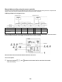
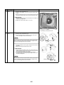
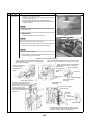
AIR CONDITIONER (MULTI TYPE)
REVISION 1 : Mar.2012
Re-edit version.( file volume down)
Contents have NOT been changed.
SERVICE MANUAL
This service manual provides relevant explanations about new indoor unit (4 series). Please refer to
the following service manuals for each indoor units.
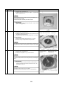
Indoor unit
Model name:
4-way Cassette Type
(MMU-AP∗∗∗2H) A08-004
2-way Cassette Type (2 series) (MMU-AP∗∗∗2WH) A10-007
Fresh Air Intake Indoor Unit Type (MMD-AP∗∗∗1HFE) A06-016
High-wall Type (2 series)
(MMK-AP∗∗∗2H)
SVM-05052-1
High-wall Type (3 series)
(MMK-AP∗∗∗3H)
SVM-09059
Other indoor units (1 series) A03-009, A03-010, A05-006, A05-007, A06-002
Indoor unit
<1-way Cassette Type (YH, SH)>
MMU-AP0074YH-E(-TR)
MMU-AP0094YH-E(-TR)
MMU-AP0124YH-E(-TR)
MMU-AP0154SH-E(-TR)
MMU-AP0184SH-E(-TR)
MMU-AP0244SH-E(-TR)
<Concealed Duct Hig h Static
Pressu re Type>
MMD-AP0184H-E(-TR)
MMD-AP0244H-E(-TR)
MMD-AP0274H-E(-TR)
MMD-AP0364H-E(-TR)
MMD-AP0484H-E(-TR)
MMD-AP0724H-E(-TR)
MMD-AP0964H-E(-TR)
<Flo or Standi ng Con cealed Type>
MML-AP0074BH-E(-TR)
MML-AP0094BH-E(-TR)
MML-AP0124BH-E(-TR)
MML-AP0154BH-E(-TR)
MML-AP0184BH-E(-TR)
MML-AP0244BH-E(-TR)
<Compact 4-way Cassette Ty pe>
MMU-AP0074MH-E(-TR)
MMU-AP0094MH-E(-TR)
MMU-AP0124MH-E(-TR)
MMU-AP0154MH-E(-TR)
MMU-AP0184MH-E(-TR)
<Ceiling Typ e>
MMC-AP0154H-E(-TR)
MMC-AP0184H-E(-TR)
MMC-AP0244H-E(-TR)
MMC-AP0274H-E(-TR)
MMC-AP0364H-E(-TR)
MMC-AP0484H-E(-TR)
<Flo or Standi ng Cabinet Type>
MML-AP0074H-E(-TR)
MML-AP0094H-E(-TR)
MML-AP0124H-E(-TR)
MML-AP0154H-E(-TR)
MML-AP0184H-E(-TR)
MML-AP0244H-E(-TR)
<Slim Duct Type>
MMD-AP0074SPH-E(-TR)
MMD-AP0094SPH-E(-TR)
MMD-AP0124SPH-E(-TR)
MMD-AP0154SPH-E(-TR)
MMD-AP0184SPH-E(-TR)
<Floor Standi ng Typ e>
MMF-AP0154H-E(-TR)
MMF-AP0184H-E(-TR)
MMF-AP0244H-E(-TR)
MMF-AP0274H-E(-TR)
MMF-AP0364H-E(-TR)
MMF-AP0484H-E(-TR)
MMF-AP0564H-E(-TR)
<Concealed Duc t Standar d Type>
MMD-AP0074BH-E(-TR),
MMD-AP0094BH-E(-TR),
MMD-AP0124BH-E(-TR),
MMD-AP0154BH-E(-TR),
MMD-AP0184BH-E(-TR),
MMD-AP0244BH-E(-TR),
MMD-AP0274BH-E(-TR),
MMD-AP0304BH-E(-TR),
MMD-AP0364BH-E(-TR),
MMD-AP0484BH-E(-TR),
MMD-AP0564BH-E(-TR)
PRINTED IN JAPAN, Apr, 201 1, TDOC
Contents
Precautions for Safety. . . . . . . . . . . . . . . . . . . . . . . . . . . . . . . . . . . . . . . . . . . . . . . . . . 6
Specifications . . . . . . . . . . . . . . . . . . . . . . . . . . . . . . . . . . . . . . . . . . . . . . . . . . . . . . . 12
1 Wiring Diagrams . . . . . . . . . . . . . . . . . . . . . . . . . . . . . . . . . . . . . . . . . . . . . . . . . . . . . 14
1-1. Compact 4-way cassette type . . . . . . . . . . . . . . . . . . . . . . . . . . . . . . . . . . . . . . . . . . . . . . . . . . . 14
1-2. 1-way cassette type (compact type YH) . . . . . . . . . . . . . . . . . . . . . . . . . . . . . . . . . . . . . . . . . . . 15
1-3. 1-way cassette type (SH) . . . . . . . . . . . . . . . . . . . . . . . . . . . . . . . . . . . . . . . . . . . . . . . . . . . . . . 16
1-4. Concealed duct standard type . . . . . . . . . . . . . . . . . . . . . . . . . . . . . . . . . . . . . . . . . . . . . . . . . . . 17
1-5. Concealed duct high static pressure type . . . . . . . . . . . . . . . . . . . . . . . . . . . . . . . . . . . . . . . . . . 18
1-6. Slim duct type . . . . . . . . . . . . . . . . . . . . . . . . . . . . . . . . . . . . . . . . . . . . . . . . . . . . . . . . . . . . . . . 20
1-7. Ceiling type . . . . . . . . . . . . . . . . . . . . . . . . . . . . . . . . . . . . . . . . . . . . . . . . . . . . . . . . . . . . . . . . . 21
1-8. Floor standing cabinet type . . . . . . . . . . . . . . . . . . . . . . . . . . . . . . . . . . . . . . . . . . . . . . . . . . . . . 22
1-9. Floor standing concealed type. . . . . . . . . . . . . . . . . . . . . . . . . . . . . . . . . . . . . . . . . . . . . . . . . . . 23
1-10. Floor standing type . . . . . . . . . . . . . . . . . . . . . . . . . . . . . . . . . . . . . . . . . . . . . . . . . . . . . . . . . . . 24
2 Parts Rating . . . . . . . . . . . . . . . . . . . . . . . . . . . . . . . . . . . . . . . . . . . . . . . . . . . . . . . . . 25
2-1. Indoor unit . . . . . . . . . . . . . . . . . . . . . . . . . . . . . . . . . . . . . . . . . . . . . . . . . . . . . . . . . . . . . . . . . . 25
3 Refrigerant Cycle Diagram . . . . . . . . . . . . . . . . . . . . . . . . . . . . . . . . . . . . . . . . . . . . . 29
4 Control Outline. . . . . . . . . . . . . . . . . . . . . . . . . . . . . . . . . . . . . . . . . . . . . . . . . . . . . . . 30
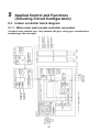
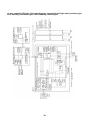
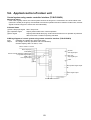
5 Applied Control and Functions (Including Circuit Configuration) . . . . . . . . . . . . . 37
5-1. Indoor controller block diagram . . . . . . . . . . . . . . . . . . . . . . . . . . . . . . . . . . . . . . . . . . . . . . . . . . 37
5-1-1. When main (sub) remote controller connected . . . . . . . . . . . . . . . . . . . . . . . . . . . . . . . 37
5-1-2. When wireless remote controller kit connected . . . . . . . . . . . . . . . . . . . . . . . . . . . . . . . 39
5-1-3. When both main (sub) remote controller and wireless remote controller kit connected . 41
5-2. Indoor printed circuit board . . . . . . . . . . . . . . . . . . . . . . . . . . . . . . . . . . . . . . . . . . . . . . . . . . . . . 43
5-3. Optional connector specifications of indoor P.C. board. . . . . . . . . . . . . . . . . . . . . . . . . . . . . . . . 45
5-4. Test operation of indoor unit . . . . . . . . . . . . . . . . . . . . . . . . . . . . . . . . . . . . . . . . . . . . . . . . . . . . 46
5-5. Method to set indoor unit function DN code . . . . . . . . . . . . . . . . . . . . . . . . . . . . . . . . . . . . . . . . 47
5-6. Applied control of indoor unit . . . . . . . . . . . . . . . . . . . . . . . . . . . . . . . . . . . . . . . . . . . . . . . . . . . 51
6 Troubleshooting . . . . . . . . . . . . . . . . . . . . . . . . . . . . . . . . . . . . . . . . . . . . . . . . . . . . . 67
6-1. Overview . . . . . . . . . . . . . . . . . . . . . . . . . . . . . . . . . . . . . . . . . . . . . . . . . . . . . . . . . . . . . . . . . . . 67
6-2. Troubleshooting method . . . . . . . . . . . . . . . . . . . . . . . . . . . . . . . . . . . . . . . . . . . . . . . . . . . . . . . 68
6-3. Troubleshooting based on information displayed on remote controller . . . . . . . . . . . . . . . . . . . . 74
6-4. Check codes displayed on remote controller and SMMS outdoor unit (7-segment display on I/F
board) and locations to be checked. . . . . . . . . . . . . . . . . . . . . . . . . . . . . . . . . . . . . . . . . . . . . . . 79
6-5. Sensor characteristics . . . . . . . . . . . . . . . . . . . . . . . . . . . . . . . . . . . . . . . . . . . . . . . . . . . . . . . . . 97
1
7 P.C. Board Exchange Procedures . . . . . . . . . . . . . . . . . . . . . . . . . . . . . . . . . . . . . . . 98
7-1. Replacement of indoor P.C. boards . . . . . . . . . . . . . . . . . . . . . . . . . . . . . . . . . . . . . . . . . . . . . . 98
8 Detachments . . . . . . . . . . . . . . . . . . . . . . . . . . . . . . . . . . . . . . . . . . . . . . . . . . . . . . . 105
8-1. 1-way cassette (SH) . . . . . . . . . . . . . . . . . . . . . . . . . . . . . . . . . . . . . . . . . . . . . . . . . . . . . . . . . 105
8-2. Compact 4-way cassette . . . . . . . . . . . . . . . . . . . . . . . . . . . . . . . . . . . . . . . . . . . . . . . . . . . . . . 114
8-3. Slim duct . . . . . . . . . . . . . . . . . . . . . . . . . . . . . . . . . . . . . . . . . . . . . . . . . . . . . . . . . . . . . . . . . . 124
8-4. Concealed duct standard. . . . . . . . . . . . . . . . . . . . . . . . . . . . . . . . . . . . . . . . . . . . . . . . . . . . . . 129
8-5. Concealed duct high static pressure . . . . . . . . . . . . . . . . . . . . . . . . . . . . . . . . . . . . . . . . . . . . . 132
8-6. Ceiling . . . . . . . . . . . . . . . . . . . . . . . . . . . . . . . . . . . . . . . . . . . . . . . . . . . . . . . . . . . . . . . . . . . . 133
8-7. Floor standing . . . . . . . . . . . . . . . . . . . . . . . . . . . . . . . . . . . . . . . . . . . . . . . . . . . . . . . . . . . . . . 141
8-8. Floor standing cabinet . . . . . . . . . . . . . . . . . . . . . . . . . . . . . . . . . . . . . . . . . . . . . . . . . . . . . . . . 144
9 Exploded Diagram / Service Parts List . . . . . . . . . . . . . . . . . . . . . . . . . . . . . . . . . . 147
9-1. 1-way cassette type (YH) . . . . . . . . . . . . . . . . . . . . . . . . . . . . . . . . . . . . . . . . . . . . . . . . . . . . . 147
9-2. 1-Way cassette type (SH) . . . . . . . . . . . . . . . . . . . . . . . . . . . . . . . . . . . . . . . . . . . . . . . . . . . . . 152
9-3. Compact 4-way cassette type . . . . . . . . . . . . . . . . . . . . . . . . . . . . . . . . . . . . . . . . . . . . . . . . . . 156
9-4. Slim duct type . . . . . . . . . . . . . . . . . . . . . . . . . . . . . . . . . . . . . . . . . . . . . . . . . . . . . . . . . . . . . . 160
9-5. Concealed duct standard type . . . . . . . . . . . . . . . . . . . . . . . . . . . . . . . . . . . . . . . . . . . . . . . . . . 164
9-6. Concealed duct high static pressure type . . . . . . . . . . . . . . . . . . . . . . . . . . . . . . . . . . . . . . . . . 178
9-7. Ceiling type . . . . . . . . . . . . . . . . . . . . . . . . . . . . . . . . . . . . . . . . . . . . . . . . . . . . . . . . . . . . . . . . 186
9-8. Floor standing type . . . . . . . . . . . . . . . . . . . . . . . . . . . . . . . . . . . . . . . . . . . . . . . . . . . . . . . . . . 193
9-9. Floor standing concealed type. . . . . . . . . . . . . . . . . . . . . . . . . . . . . . . . . . . . . . . . . . . . . . . . . . 202
9-10. Floor standing cabinet type . . . . . . . . . . . . . . . . . . . . . . . . . . . . . . . . . . . . . . . . . . . . . . . . . . . . 208
2
Original instruction
Please read carefully through these instructions that contain important information which complies with the
“Machinery” Directive (Directive 2006/42/EC), and ensure that you understand them.
Generic Denomination: Air Conditioner
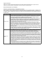
Definition of Qualified Installer or Qualified Service Person
The air conditioner must be installed, maintained, repaired and removed by a qualified installer or qualified service
person. When any of these jobs is to be done, ask a qualified installer or qualified service person to do them for you.
A qualified installer or qualified service person is an agent who has the qualifications and knowledge described in
the table below.
Agent
Qualifications and knowledge which the agent must have
Qualified installer
• The qualified installer is a person who installs, maintains, relocates and removes the air conditioners
made by Toshiba Carrier Corporation. He or she has been trained to install, maintain, relocate and
remove the air conditioners made by Toshiba Carrier Corporation or, alternatively, he or she has been
instructed in such operations by an individual or individuals who have been trained and is thus
thoroughly acquainted with the knowledge related to these operations.
• The qualified installer who is allowed to do the electrical work involved in installation, relocation and
removal has the qualifications pertaining to this electrical work as stipulated by the local laws and
regulations, and he or she is a person who has been trained in matters relating to electrical work on
the air conditioners made by Toshiba Carrier Corporation or, alternatively, he or she has been
instructed in such matters by an individual or individuals who have been trained and is thus thoroughly
acquainted with the knowledge related to this work.
• The qualified installer who is allowed to do the refrigerant handling and piping work involved in
installation, relocation and removal has the qualifications pertaining to this refrigerant handling and
piping work as stipulated by the local laws and regulations, and he or she is a person who has been
trained in matters relating to refrigerant handling and piping work on the air conditioners made by
Toshiba Carrier Corporation or, alternatively, he or she has been instructed in such matters by an
individual or individuals who have been trained and is thus thoroughly acquainted with the knowledge
related to this work.
• The qualified installer who is allowed to work at heights has been trained in matters relating to working
at heights with the air conditioners made by Toshiba Carrier Corporation or, alternatively, he or she
has been instructed in such matters by an individual or individuals who have been trained and is thus
thoroughly acquainted with the knowledge related to this work.
Qualified service
person
• The qualified service person is a person who installs, repairs, maintains, relocates and removes the
air conditioners made by Toshiba Carrier Corporation. He or she has been trained to install, repair,
maintain, relocate and remove the air conditioners made by Toshiba Carrier Corporation or,
alternatively, he or she has been instructed in such operations by an individual or individuals who have
been trained and is thus thoroughly acquainted with the knowledge related to these operations.
• The qualified service person who is allowed to do the electrical work involved in installation, repair,
relocation and removal has the qualifications pertaining to this electrical work as stipulated by the local
laws and regulations, and he or she is a person who has been trained in matters relating to electrical
work on the air conditioners made by Toshiba Carrier Corporation or, alternatively, he or she has been
instructed in such matters by an individual or individuals who have been trained and is thus thoroughly
acquainted with the knowledge related to this work.
• The qualified service person who is allowed to do the refrigerant handling and piping work involved in
installation, repair, relocation and removal has the qualifications pertaining to this refrigerant handling
and piping work as stipulated by the local laws and regulations, and he or she is a person who has
been trained in matters relating to refrigerant handling and piping work on the air conditioners made
by Toshiba Carrier Corporation or, alternatively, he or she has been instructed in such matters by an
individual or individuals who have been trained and is thus thoroughly acquainted with the knowledge
related to this work.
• The qualified service person who is allowed to work at heights has been trained in matters relating to
working at heights with the air conditioners made by Toshiba Carrier Corporation or, alternatively, he
or she has been instructed in such matters by an individual or individuals who have been trained and
is thus thoroughly acquainted with the knowledge related to this work.
3
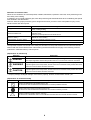
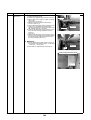
Definition of Protective Gear
When the air conditioner is to be transported, installed, maintained, repaired or removed, wear protective gloves
and ‘safety’ work clothing.
In addition to such normal protective gear, wear the protective gear described below when undertaking the special
work detailed in the table below.
Failure to wear the proper protective gear is dangerous because you will be more susceptible to injury, burns,
electric shocks and other injuries.
Work undertaken
Protective gear worn
All types of work
Protective gloves
‘Safety’ working clothing
Electrical-related work
Gloves to provide protection for electricians and from heat
Insulating shoes
Clothing to provide protection from electric shock
Work done at heights
(50 cm or more)
Helmets for use in industry
Transportation of heavy objects
Shoes with additional protective toe cap
Repair of outdoor unit
Gloves to provide protection for electricians and from heat
The important contents concerned to the safety are described on the product itself and on this Service Manual.
Please read this Service Manual after understanding the described items thoroughly in the following contents
(Indications / Illustrated marks), and keep them.
[Explanation of indications]
Indication
Explanation
DANGER
Indicates contents assumed that an imminent danger causing a death or serious injury of
the repair engineers and the third parties when an incorrect work has been executed.
WARNING
Indicates possibilities assumed that a danger causing a death or serious injury of the
repair engineers, the third parties, and the users due to troubles of the product after work
when an incorrect work has been executed.
CAUTION
Indicates contents assumed that an injury or property damage (*) may be caused on the
repair engineers, the third parties, and the users due to troubles of the product after work
when an incorrect work has been executed.
* Property damage: Enlarged damage concerned to property, furniture, and domestic animal / pet
[Explanation of illustrated marks]
Mark
Explanation
Indicates prohibited items (Forbidden items to do)
The sentences near an illustrated mark describe the concrete prohibited contents.
Indicates mandatory items (Compulsory items to do)
The sentences near an illustrated mark describe the concrete mandatory contents.
Indicates cautions (Including danger / warning)
The sentences or illustration near or in an illustrated mark describe the concrete cautious contents.
4
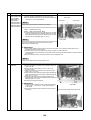
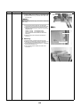
Warning Indications on the Air Conditioner Unit
[Confirmation of warning label on the main unit]
Confirm that labels are indicated on the specified positions
If removing the label during parts replace, stick it as the original.
Warning indication
Description
WARNING
ELECTRICAL SHOCK HAZARD
Disconnect all remote electric power supplies before servicing.
WARNING
Moving parts.
Do not operate unit with grille removed.
Stop the unit before the servicing.
CAUTION
High temperature parts.
You might get burned when removing this panel.
CAUTION
Do not touch the aluminium fins of the unit.
Doing so may result in injury.
CAUTION
BURST HAZARD
Open the service valves before the operation, otherwise there might be the
burst.
CAUTION
Do not climb onto the fan guard.
Doing so may result in injury.
5
Precautions for Safety
The manufacturer shall not assume any liability for the damage caused by not observing the description of this
manual.
DANGER
Before carrying out the installation, maintenance, repair or removal work, be sure to set the circuit breaker for
both the indoor and outdoor units to the OFF position. Otherwise, electric shocks may result.
Before opening the intake grille of the indoor unit or service panel of the outdoor unit, set the circuit breaker to
the OFF position.
Failure to set the circuit breaker to the OFF position may result in electric shocks through contact with the interior
parts.
Only a qualified installer (*1) or qualified service person (*1) is allowed to remove the intake grille of the indoor
unit or service panel of the outdoor unit and do the work required.
Before starting to repair the outdoor unit fan or fan guard, be absolutely sure to set the circuit breaker to the
OFF position, and place a “Work in progress” sign on the circuit breaker.
Turn off
breaker.
When cleaning the filter or other parts of the indoor unit, set the circuit breaker to OFF without fail, and place a
“Work in progress” sign near the circuit breaker before proceeding with the work.
When you have noticed that some kind of trouble (such as when an error display has appeared, there is a smell
of burning, abnormal sounds are heard, the air conditioner fails to cool or heat or water is leaking) has occurred
in the air conditioner, do not touch the air conditioner yourself but set the circuit breaker to the OFF position,
and contact a qualified service person. Take steps to ensure that the power will not be turned on (by marking
“out of service” near the circuit breaker, for instance) until qualified service person arrives. Continuing to use the
air conditioner in the trouble status may cause mechanical problems to escalate or result in electric shocks or
other failure.
When you access inside of the service panel to repair electric parts, wait for about five minutes after turning off
the breaker. Do not start repairing immediately.Otherwise you may get electric shock by touching terminals of
Electric shock high-voltage capacitors. Natural discharge of the capacitor takes about five minutes.
hazard
Place a “Work in progress” sign near the circuit breaker while the installation, maintenance, repair or removal
work is being carried out.
There is a danger of electric shocks if the circuit breaker is set to ON by mistake.
Prohibition
Stay on
protection
Before operating the air conditioner after having completed the work, check that the electrical parts box cover
of the indoor unit and service panel of the outdoor unit are closed, and set the circuit breaker to the ON position.
You may receive an electric shock if the power is turned on without first conducting these checks.
If, in the course of carrying out repairs, it becomes absolutely necessary to check out the electrical parts with
the electrical parts box cover of one or more of the indoor units and the service panel of the outdoor unit
removed in order to find out exactly where the trouble lies, wear insulated heat-resistant gloves, insulated boots
and insulated work overalls, and take care to avoid touching any live parts.
You may receive an electric shock if you fail to heed this warning. Only qualified service person (*1) is allowed
to do this kind of work.
6
WARNING
Before starting to repair the air conditioner, read carefully through the Service Manual, and repair the air
conditioner by following its instructions.
Only qualified service person (*1) is allowed to repair the air conditioner.
Repair of the air conditioner by unqualified person may give rise to a fire, electric shocks, injury, water leaks and
/ or other problems.
Do not use any refrigerant different from the one specified for complement or replacement.
Otherwise, abnormally high pressure may be generated in the refrigeration cycle, which may result in a failure
or explosion of the product or an injury to your body.
Only a qualified installer (*1) or qualified service person (*1) is allowed to carry out the electrical work of the air
conditioner.
Under no circumstances must this work be done by an unqualified individual since failure to carry out the work
properly may result in electric shocks and / or electrical leaks.
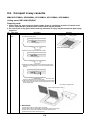
When transporting the air conditioner, wear shoes with protective toe caps, protective gloves and other
protective clothing.
When connecting the electrical wires, repairing the electrical parts or undertaking other electrical jobs, wear
gloves to provide protection for electricians and from heat, insulating shoes and clothing to provide protection
from electric shocks.
Failure to wear this protective gear may result in electric shocks.
Electrical wiring work shall be conducted according to law and regulation in the community and installation
manual. Failure to do so may result in electrocution or short circuit.
Only a qualified installer (*1) or qualified service person (*1) is allowed to undertake work at heights using a
stand of 50 cm or more or to remove the intake grille of the indoor unit to undertake work.
General
When working at heights, use a ladder which complies with the ISO 14122 standard, and follow the procedure
in the ladder’s instructions.
Also wear a helmet for use in industry as protective gear to undertake the work.
When working at heights, put a sign in place so that no-one will approach the work location, before proceeding
with the work.
Parts and other objects may fall from above, possibly injuring a person below.
When executing address setting, test run, or troubleshooting through the checking window on the electric parts
box, put on insulated gloves to provide protection from electric shock. Otherwise you may receive an electric
shock.
Do not touch the aluminum fin of the outdoor unit.
You may injure yourself if you do so. If the fin must be touched for some reason, first put on protective gloves
and safety work clothing, and then proceed.
Do not climb onto or place objects on top of the outdoor unit.
You may fall or the objects may fall off of the outdoor unit and result in injury.
When transporting the air conditioner, wear shoes with additional protective toe caps.
When transporting the air conditioner, do not take hold of the bands around the packing carton.
You may injure yourself if the bands should break.
Be sure that a heavy unit (10 kg or heavier) such as a compressor is carried by two persons.
This air conditioner has passed the pressure test as specified in IEC 60335-2-40 Annex EE.
Before troubleshooting or repair work, check the earth wire is connected to the earth terminals of the main unit,
otherwise an electric shock is caused when a leak occurs.If the earth wire is not correctly connected, contact
an electric engineer for rework.
After completing the repair or relocation work, check that the ground wires are connected properly.
Check earth
wires.
Prohibition of
modification.
Be sure to connect earth wire. (Grounding work) Incomplete grounding causes an electric shock.
Do not connect ground wires to gas pipes, water pipes, and lightning rods or ground wires for telephone wires.
Do not modify the products.Do not also disassemble or modify the parts.
It may cause a fire, electric shock or injury.
When any of the electrical parts are to be replaced, ensure that the replacement parts satisfy the specifications
given in the Service Manual (or use the parts contained on the parts list in the Service Manual).
Use of any parts which do not satisfy the required specifications may give rise to electric shocks, smoking and
Use specified / or a fire.
parts.
7
If, in the course of carrying out repairs, it becomes absolutely necessary to check out the electrical parts with
the electrical parts box cover of one or more of the indoor units and the service panel of the outdoor unit
removed in order to find out exactly where the trouble lies, put a sign in place so that no-one will approach the
Do not bring a
child close to work location before proceeding with the work. Third-party individuals may enter the work site and receive
electric shocks if this warning is not heeded.
the
equipment.
Connect the cut-off lead wires with crimp contact, etc., put the closed end side upward and then apply a watercut method, otherwise a leak or production of fire is caused at the users’ side.
Insulating
measures
No fire
When performing repairs using a gas burner, replace the refrigerant with nitrogen gas because the oil that coats
the pipes may otherwise burn.
When repairing the refrigerating cycle, take the following measures.
1) Be attentive to fire around the cycle. When using a gas stove, etc., be sure to put out fire before work;
otherwise the oil mixed with refrigerant gas may catch fire.
2) Do not use a welder in the closed room. When using it without ventilation, carbon monoxide poisoning may
be caused.
3) Do not bring inflammables close to the refrigerant cycle, otherwise fire of the welder may catch the
inflammables.
The refrigerant used by this air conditioner is the R410A.
Check the used refrigerant name and use tools and materials of the parts which match with it.
For the products which use R410A refrigerant, the refrigerant name is indicated at a position on the outdoor unit
where is easy to see. To prevent miss-charging, the route of the service port is changed from one of the former
R22.
For an air conditioner which uses R410A, never use other refrigerant than R410A. For an air conditioner which
uses other refrigerant (R22, etc.), never use R410A.
If different types of refrigerant are mixed, abnormal high pressure generates in the refrigerating cycle and an
injury due to breakage may be caused.
When the air conditioner has been installed or relocated, follow the instructions in the Installation Manual and
purge the air completely so that no gases other than the refrigerant will be mixed in the refrigerating cycle.
Failure to purge the air completely may cause the air conditioner to malfunction.
Refrigerant
Do not charge refrigerant additionally. If charging refrigerant additionally when refrigerant gas leaks, the
refrigerant composition in the refrigerating cycle changes resulted in change of air conditioner characteristics or
refrigerant over the specified standard amount is charged and an abnormal high pressure is applied to the inside
of the refrigerating cycle resulted in cause of breakage or injury. Therefore if the refrigerant gas leaks, recover
the refrigerant in the air conditioner, execute vacuuming, and then newly recharge the specified amount of liquid
refrigerant.
In this time, never charge the refrigerant over the specified amount.
When recharging the refrigerant in the refrigerating cycle, do not mix the refrigerant or air other than R410A into
the specified refrigerant. If air or others is mixed with the refrigerant, abnormal high pressure generates in the
refrigerating cycle resulted in cause of injury due to breakage.
After installation work, check the refrigerant gas does not leak. If the refrigerant gas leaks in the room,
poisonous gas generates when gas touches to fire such as fan heater, stove or cocking stove though the
refrigerant gas itself is innocuous.
Never recover the refrigerant into the outdoor unit. When the equipment is moved or repaired, be sure to recover
the refrigerant with recovering device.
The refrigerant cannot be recovered in the outdoor unit; otherwise a serious accident such as breakage or injury
is caused.
Assembly /
Wiring
Insulator
check
Ventilation
After repair work, surely assemble the disassembled parts, and connect and lead the removed wires as before.
Perform the work so that the cabinet or panel does not catch the inner wires.
If incorrect assembly or incorrect wire connection was done, a disaster such as a leak or fire is caused at user’s
side.
After the work has finished, be sure to use an insulation tester set (500 V Megger) to check the resistance is
1 M: or more between the charge section and the non-charge metal section (Earth position).
If the resistance value is low, a disaster such as a leak or electric shock is caused at user’s side.
When the refrigerant gas leaks during work, execute ventilation.
If the refrigerant gas touches to a fire, poisonous gas generates. A case of leakage of the refrigerant and the
closed room full with gas is dangerous because a shortage of oxygen occurs. Be sure to execute ventilation.
8
When the refrigerant gas leaks, find up the leaked position and repair it surely.
If the leaked position cannot be found up and the repair work is interrupted, pump-down and tighten the service
valve, otherwise the refrigerant gas may leak into the room.
The poisonous gas generates when gas touches to fire such as fan heater, stove or cocking stove though the
refrigerant gas itself is innocuous.
When installing equipment which includes a large amount of charged refrigerant such as a multi air conditioner
in a sub-room, it is necessary that the density does not the limit even if the refrigerant leaks.
If the refrigerant leaks and exceeds the limit density, an accident of shortage of oxygen is caused.
Compulsion
Tighten the flare nut with a torque wrench in the specified manner.
Excessive tighten of the flare nut may cause a crack in the flare nut after a long period, which may result in
refrigerant leakage.
Nitrogen gas must be used for the airtight test.
The charge hose must be connected in such a way that it is not slack.
For the installation / moving / reinstallation work, follow to the Installation Manual.
If an incorrect installation is done, a trouble of the refrigerating cycle, water leak, electric shock or fire is caused.
Once the repair work has been completed, check for refrigerant leaks, and check the insulation resistance and
water drainage.
Then perform a trial run to check that the air conditioner is running properly.
After repair work has finished, check there is no trouble. If check is not executed, a fire, electric shock or injury
may be caused. For a check, turn off the power breaker.
Check after
repair
After repair work (installation of front panel and cabinet) has finished, execute a test run to check there is no
generation of smoke or abnormal sound.
If check is not executed, a fire or an electric shock is caused. Before test run, install the front panel and cabinet.
Be sure to fix the screws back which have been removed for installation or other purposes.
Check the following matters before a test run after repairing piping.
• Connect the pipes surely and there is no leak of refrigerant.
• The valve is opened.
Do not
Running the compressor under condition that the valve closes causes an abnormal high pressure resulted in
operate the damage of the parts of the compressor and etc. and moreover if there is leak of refrigerant at connecting section
unit with the
valve closed. of pipes, the air is sucked and causes further abnormal high pressure resulted in burst or injury.
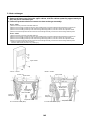
Only a qualified installer (*1) or qualified service person (*1) is allowed to relocate the air conditioner. It is
dangerous for the air conditioner to be relocated by an unqualified individual since a fire, electric shocks, injury,
water leakage, noise and / or vibration may result.
Check the following items after reinstallation.
1) The earth wire is correctly connected.
2) The power cord is not caught in the product.
3) There is no inclination or unsteadiness and the installation is stable.
Check after
reinstallation If check is not executed, a fire, an electric shock or an injury is caused.
When carrying out the pump-down work shut down the compressor before disconnecting the refrigerant pipe.
Disconnecting the refrigerant pipe with the service valve left open and the compressor still operating will cause
air, etc. to be sucked in, raising the pressure inside the refrigeration cycle to an abnormally high level, and
possibly resulting in reputing, injury, etc.
When the service panel of the outdoor unit is to be opened in order for the compressor or the area around this
part to be repaired immediately after the air conditioner has been shut down, set the circuit breaker to the OFF
position, and then wait at least 10 minutes before opening the service panel.
If you fail to heed this warning, you will run the risk of burning yourself because the compressor pipes and other
parts will be very hot to the touch. In addition, before proceeding with the repair work, wear the kind of insulated
heat-resistant gloves designed to protect electricians.
Take care not to get burned by compressor pipes or other parts when checking the cooling cycle while running
the unit as they get heated while running. Be sure to put on gloves providing protection for electric shock and
heat.
Cooling check When the service panel of the outdoor unit is to be opened in order for the fan motor, reactor, inverter or the
areas around these parts to be repaired immediately after the air conditioner has been shut down, set the circuit
breaker to the OFF position, and then wait at least 10 minutes before opening the service panel.
If you fail to heed this warning, you will run the risk of burning yourself because the fan motor, reactor, inverter
heat sink and other parts will be very hot to the touch.
In addition, before proceeding with the repair work, wear the kind of insulated heat-resistant gloves designed to
protect electricians.
9
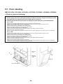
Only a qualified installer (*1) or qualified service person (*1) is allowed to install the air conditioner. If the air
conditioner is installed by an unqualified individual, a fire, electric shocks, injury, water leakage, noise and / or
vibration may result.
Before starting to install the air conditioner, read carefully through the Installation Manual, and follow its
instructions to install the air conditioner.
Be sure to use the company-specified products for the separately purchased parts. Use of non-specified
products may result in fire, electric shock, water leakage or other failure. Have the installation performed by a
qualified installer.
Do not supply power from the power terminal block equipped on the outdoor unit to another outdoor unit.
Capacity overflow may occur on the terminal block and may result in fire.
Do not install the air conditioner in a location that may be subject to a risk of expire to a combustible gas.
If a combustible gas leaks and becomes concentrated around the unit, a fire may occur.
Installation
Install the indoor unit at least 2.5 m above the floor level since otherwise the users may injure themselves or
receive electric shocks if they poke their fingers or other objects into the indoor unit while the air conditioner is
running.
Install a circuit breaker that meets the specifications in the installation manual and the stipulations in the local
regulations and laws.
Install the circuit breaker where it can be easily accessed by the qualified service person (*1).
If you install the unit in a small room, take appropriate measures to prevent the refrigerant from exceeding the
limit concentration even if it leaks. Consult the dealer from whom you purchased the air conditioner when you
implement the measures. Accumulation of highly concentrated refrigerant may cause an oxygen deficiency
accident.
Do not place any combustion appliance in a place where it is directly exposed to the wind of air conditioner,
otherwise it may cause imperfect combustion.
Explanations given to user
If you have discovered that the fan grille is damaged, do not approach the outdoor unit but set the circuit breaker
to the OFF position, and contact a qualified service person to have the repairs done.
Do not set the circuit breaker to the ON position until the repairs are completed.
Relocation
• Only a qualified installer (*1) or qualified service person (*1) is allowed to relocate the air conditioner.
It is dangerous for the air conditioner to be relocated by an unqualified individual since a fire, electric shocks,
injury, water leakage, noise and / or vibration may result.
• When carrying out the pump-down work shut down the compressor before disconnecting the refrigerant pipe.
Disconnecting the refrigerant pipe with the service valve left open and the compressor still operating will cause
air, etc. to be sucked in, raising the pressure inside the refrigeration cycle to an abnormally high level, and
possibly resulting in reputing, injury, etc.
(*1) Refer to the “Definition of Qualified Installer or Qualified Service Person”
10
Declaration of Conformity
Manufacturer:
Toshiba Carrier Corporation
336 Tadehara, Fuji-shi, Shizuoka-ken 416-8521 JAPAN
Authorized Representative /
TCF holder:
Nick Ball
Toshiba EMEA Engineering Director
Toshiba Carrier UK Ltd.
Porsham Close, Belliver Industrial Estate,
PLYMOUTH, Devon, PL6 7DB.
United Kingdom
Hereby declares that the machinery described below:
Generic Denomination:
Air Conditioner
Model / type:
Indoor unit
<1-way Cassette Type (YH, SH)>
MMU-AP0074YH-E(TR), MMU-AP0094YH-E(TR), MMU-AP0124YH-E(TR),
MMU-AP0154SH-E(TR), MMU-AP0184SH-E(TR), MMU-AP0244SH-E(TR)
<Compact 4-way Cassette Type>
MMU-AP0074MH-E(TR), MMU-AP0094MH-E(TR), MMU-AP0124MH-E(TR), MMU-AP0154MH-E(TR),
MMU-AP0184MH-E(TR)
<Slim Duct Type>
MMD-AP0074SPH-E(TR), MMD-AP0094SPH-E(TR), MMD-AP0124SPH-E(TR), MMD-AP0154SPH-E(TR),
MMD-AP0184SPH-E(TR)
<Concealed Duct Standard Type>
MMD-AP0074BH-E(TR), MMD-AP0094BH-E(TR), MMD-AP0124BH-E(TR), MMD-AP0154BH-E(TR),
MMD-AP0184BH-E(TR), MMD-AP0244BH-E(TR), MMD-AP0274BH-E(TR), MMD-AP0304BH-E(TR),
MMD-AP0364BH-E(TR), MMD-AP0484BH-E(TR), MMD-AP0564BH-E(TR)
<Concealed Duct High Static Pressure Type>
MMD-AP0184H-E(TR), MMD-AP0244H-E(TR), MMD-AP0274H-E(TR), MMD-AP0364H-E(TR),
MMD-AP0484H-E(TR), MMD-AP0724H-E(TR), MMD-AP0964H-E(TR)
<Ceiling Type>
MMC-AP0154H-E(TR), MMC-AP0184H-E(TR), MMC-AP0244H-E(TR), MMC-AP0274H-E(TR),
MMC-AP0364H-E(TR), MMC-AP0484H-E(TR)
<Floor Standing Type>
MMF-AP0154H-E(TR), MMF-AP0184H-E(TR), MMF-AP0244H-E(TR), MMF-AP0274H-E(TR),
MMF-AP0364H-E(TR), MMF-AP0484H-E(TR), MMF-AP0564H-E(TR)
<Floor Standing Concealed Type>
MML-AP0074BH-E(TR), MML-AP0094BH-E(TR), MML-AP0124BH-E(TR), MML-AP0154BH-E(TR),
MML-AP0184BH-E(TR), MML-AP0244BH-E(TR)
<Floor Standing Cabinet Type>
MML-AP0074H-E(TR), MML-AP0094H-E(TR), MML-AP0124H-E(TR), MML-AP0154H-E(TR),
MML-AP0184H-E(TR), MML-AP0244H-E(TR)
Commercial name:
Super Modular Multi System Air Conditioner
Super Heat Recovery Multi System Air Conditioner
MiNi-Super Modular Multi System Air Conditioner (MiNi-SMMS series)
Complies with the provisions of the “Machinery” Directive (Directive 2006/42/EC) and the regulations transposing into national law
Complies with the provisions of the following harmonized standard:
EN 378-2: 2008+A1:2009
NOTE
This declaration becomes invalid if technical or operational modifications are introduced without the manufacturer’s
consent.
11
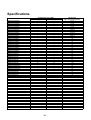
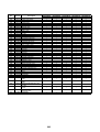
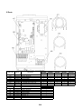
Specifications
Model
MMU-AP0074MH-E
MMU-AP0094MH-E
MMU-AP0124MH-E
MMU-AP0154MH-E
MMU-AP0184MH-E
MMU-AP0074YH-E
MMU-AP0094YH-E
MMU-AP0124YH-E
MMU-AP0154SH-E
MMU-AP0184SH-E
MMU-AP0244SH-E
MMD-AP0074BH-E
MMD-AP0094BH-E
MMD-AP0124BH-E
MMD-AP0154BH-E
MMD-AP0184BH-E
MMD-AP0244BH-E
MMD-AP0274BH-E
MMD-AP0304BH-E
MMD-AP0364BH-E
MMD-AP0484BH-E
MMD-AP0564BH-E
MMD-AP0184H-E
MMD-AP0244H-E
MMD-AP0274H-E
MMD-AP0364H-E
MMD-AP0484H-E
MMD-AP0724H-E
MMD-AP0964H-E
MMD-AP0074SPH-E
MMD-AP0094SPH-E
MMD-AP0124SPH-E
MMD-AP0154SPH-E
MMD-AP0184SPH-E
MMC-AP0154H-E
MMC-AP0184H-E
MMC-AP0244H-E
MMC-AP0274H-E
MMC-AP0364H-E
MMC-AP0484H-E
MML-AP0074H-E
MML-AP0094H-E
MML-AP0124H-E
MML-AP0154H-E
MML-AP0184H-E
MML-AP0244H-E
MML-AP0074BH-E
MML-AP0094BH-E
MML-AP0124BH-E
MML-AP0154BH-E
MML-AP0184BH-E
MML-AP0244BH-E
MMF-AP0154H-E
MMF-AP0184H-E
MMF-AP0244H-E
MMF-AP0274H-E
MMF-AP0364H-E
MMF-AP0484H-E
MMF-AP0564H-E
Sound power level (dBA)
Cooling
Heating
*
*
*
*
*
*
*
*
*
*
*
*
*
*
*
*
*
*
*
*
*
*
*
*
*
*
*
*
*
*
*
*
*
*
*
*
*
*
*
*
*
*
*
*
*
*
*
*
*
*
*
*
*
*
*
*
70
70
*
*
*
*
*
*
*
*
*
*
*
*
*
*
*
*
*
*
*
*
*
*
*
*
*
*
*
*
*
*
*
*
*
*
*
*
*
*
*
*
*
*
*
*
*
*
*
*
*
*
*
*
*
*
*
*
72
72
72
72
12
Weight (kg)
Main unit (Ceiling panel)
17 (3)
17 (3)
17 (3)
17 (3)
17 (3)
22 (3.5)
22 (3.5)
22 (3.5)
21 (5.5)
21 (5.5)
22 (5.5)
28
28
28
32
32
43
43
43
55
55
55
50
52
52
56
67
160
160
22
22
22
23
23
22
22
26
26
34
34
37
37
37
37
40
40
21
21
21
29
29
29
48
48
49
49
65
65
65
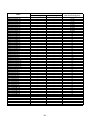
Model
MMU-AP0074MH-TR
MMU-AP0094MH-TR
MMU-AP0124MH-TR
MMU-AP0154MH-TR
MMU-AP0184MH-TR
MMU-AP0074YH-TR
MMU-AP0094YH-TR
MMU-AP0124YH-TR
MMU-AP0154SH-TR
MMU-AP0184SH-TR
MMU-AP0244SH-TR
MMD-AP0074BH-TR
MMD-AP0094BH-TR
MMD-AP0124BH-TR
MMD-AP0154BH-TR
MMD-AP0184BH-TR
MMD-AP0244BH-TR
MMD-AP0274BH-TR
MMD-AP0304BH-TR
MMD-AP0364BH-TR
MMD-AP0484BH-TR
MMD-AP0564BH-TR
MMD-AP0184H-TR
MMD-AP0244H-TR
MMD-AP0274H-TR
MMD-AP0364H-TR
MMD-AP0484H-TR
MMD-AP0724H-TR
MMD-AP0964H-TR
MMD-AP0074SPH-TR
MMD-AP0094SPH-TR
MMD-AP0124SPH-TR
MMD-AP0154SPH-TR
MMD-AP0184SPH-TR
MMC-AP0154H-TR
MMC-AP0184H-TR
MMC-AP0244H-TR
MMC-AP0274H-TR
MMC-AP0364H-TR
MMC-AP0484H-TR
MML-AP0074H-TR
MML-AP0094H-TR
MML-AP0124H-TR
MML-AP0154H-TR
MML-AP0184H-TR
MML-AP0244H-TR
MML-AP0074BH-TR
MML-AP0094BH-TR
MML-AP0124BH-TR
MML-AP0154BH-TR
MML-AP0184BH-TR
MML-AP0244BH-TR
MMF-AP0154H-TR
MMF-AP0184H-TR
MMF-AP0244H-TR
MMF-AP0274H-TR
MMF-AP0364H-TR
MMF-AP0484H-TR
MMF-AP0564H-TR
Sound power level (dBA)
Cooling
Heating
*
*
*
*
*
*
*
*
*
*
*
*
*
*
*
*
*
*
*
*
*
*
*
*
*
*
*
*
*
*
*
*
*
*
*
*
*
*
*
*
*
*
*
*
*
*
*
*
*
*
*
*
*
*
*
*
70
70
*
*
*
*
*
*
*
*
*
*
*
*
*
*
*
*
*
*
*
*
*
*
*
*
*
*
*
*
*
*
*
*
*
*
*
*
*
*
*
*
*
*
*
*
*
*
*
*
*
*
*
*
*
*
*
*
72
72
72
72
13
Weight (kg)
Main unit (Ceiling panel)
17 (3)
17 (3)
17 (3)
17 (3)
17 (3)
22 (3.5)
22 (3.5)
22 (3.5)
21 (5.5)
21 (5.5)
22 (5.5)
28
28
28
32
32
43
43
43
55
55
55
50
52
52
56
67
160
160
22
22
22
23
23
22
22
26
26
34
34
37
37
37
37
40
40
21
21
21
29
29
29
48
48
49
49
65
65
65
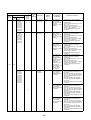
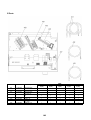
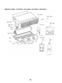
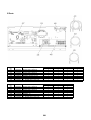
14
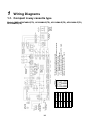
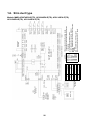
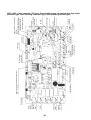
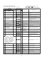
Symbol
CN**
DM
F301,302
FM
FS
LM1,2
PMV
RY302
TA
TB01,02
TC1,2,TCJ
Flow selector unit
Earth screw
Power supply
1~50Hz 220-240V
1~60Hz 220V
Indoor unit
Earth screw
Parts Name
Connector
Drain Pump Motor
Fuse
Fan Motor
Float Switch
Louver Motor
Pulse Motor Valve
Drain Control Relay
Indoor temp sensor
Terminal Block
Temp sensor
COLOR
IDENTIFICATION
RED : RED
WHI : WHITE
YEL : YELLOW
BLU : BLUE
BLK : BLACK
GRY : GRAY
PNK : PINK
ORN : ORANGE
BRW : BROWN
GRN : GREEN
Outdoor unit
1. Broken line indicate the wiring at site.
Long dashed short dashed line indicate the accessories.
2.
indicates the terminal block.
indicates the connection terminal.
indicates the connector on the control P.C. board.
3. indicates the protection ground.
4.
indicates the control P.C. board.
Power
supply
circuit
Control P.C. Board
for Indoor Unit
(High ceiling
reshuffling)
Wired Remote
Controller
Adapter for
Wireless
Remote
Controller
1
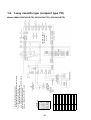
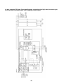
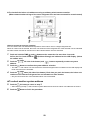
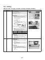
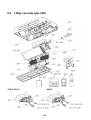
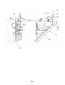
Wiring Diagrams
1-1. Compact 4-way cassette type
Models: MMU-AP0074MH-E(TR), AP0094MH-E(TR), AP0124MH-E(TR), AP0154MH-E(TR),
AP0184MH-E(TR)
15
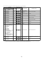
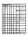
Symbol
CN**
DM
F301,302
FM
FS
LM
PMV
RY001
RY002
RY005,006,007
TA
TB01,02
TC,TCJ
TR
Parts Name
Connector
Drain Pump Motor
Fuse
Fan Motor
Float Switch
Louver Motor
Pulse Motor Valve
Louver Control Relay
Drain Control Relay
Fan Motor Control Relay
Indoor temp sensor
Terminal Block
Temp sensor
Transformer
COLOR
IDENTIFICATION
RED : RED
WHI : WHITE
YEL : YELLOW
BLU : BLUE
BLK : BLACK
GRY : GRAY
PNK : PINK
ORN : ORANGE
BRW : BROWN
GRN : GREEN
Outdoor unit
Line Filter
Power supply
1~50Hz 220-240V
1~60Hz 220V
Indoor unit
Earth screw
Flow selector unit
Earth screw
Remote Controller
1. Broken line indicate the wiring at site.
Long dashed short dashed line indicate the accessories.
2.
indicates the terminal block.
indicates the connection terminal.
indicates the connector on the control P.C. board.
3. indicates the protection ground.
4.
indicates the control P.C. board.
Sub P.C. Board
Power
supply
circuit
Control P.C. Board
for Indoor Unit
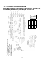
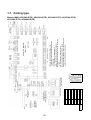
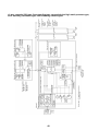
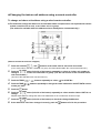
1-2. 1-way cassette type (compact type YH)
Models: MMU-AP0074YH-E(TR), AP0094YH-E(TR), AP0124YH-E(TR)
Parts Name
Connector
Drain Pump Motor
Fuse
Fan Motor
Float Switch
Louver Motor
Pulse Motor Valve
Drain Control Relay
Indoor temp sensor
Terminal Block
Temp sensor
COLOR
IDENTIFICATION
RED : RED
WHI : WHITE
YEL : YELLOW
BLU : BLUE
BLK : BLACK
GRY : GRAY
PNK : PINK
ORN : ORANGE
BRW : BROWN
GRN : GREEN
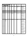
Symbol
CN**
DM
F301,302
FM
FS
LM
PMV
RY302
TA
TB01,02
TC1,2,TCJ
16
Outdoor unit
Indoor unit
Earth screw
Power supply
1~50Hz 220-240V
1~60Hz 220V
Wired Remote
Controller
Flow selector unit
Earth screw
Adapter for
Wireless Remote
Controller
1. Broken line indicate the wiring at site.
Long dashed short dashed line indicate the accessories.
2.
indicates the terminal block.
indicates the connection terminal.
indicates the connector on the control P.C. board.
3. indicates the protection ground.
4.
indicates the control P.C. board.
Power
supply
circuit
Control P.C. Board
for Indoor Unit
(High ceiling
reshuffling)
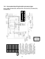
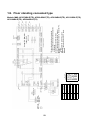
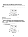
1-3. 1-way cassette type (SH)
Models: MMU-AP0154SH-E(TR), AP0184SH-E(TR), AP0244SH-E(TR)
Indoor unit
Earth screw
Reactor
Outdoor unit
Power supply
1~50Hz 220-240V
1~60Hz 220V
Flow selector unit
Earth screw
Wired Remote
Controller
1. Broken line indicate the wiring at site.
Long dashed short dashed line indicate the accessories.
2.
indicates the terminal block.
indicates the connection terminal.
indicates the connector on the control P.C. board.
3. indicates the protection ground.
4.
indicates the control P.C. board.
Adapter for
Wireless Remote
Controller
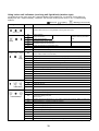
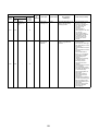
Symbol
CN**
DM
F301,302
FM
FS
PMV
RY302
TA
TB01,02
TC1,2,TCJ
Power
supply
circuit
Parts Name
Connector
Drain Pump Motor
Fuse
Fan Motor
Float Switch
Pulse Motor Valve
Drain Control Relay
Indoor temp sensor
Terminal Block
Temp sensor
Control P.C. Board
for Indoor Unit
(High ceiling
reshuffling)
COLOR
IDENTIFICATION
RED : RED
WHI : WHITE
YEL : YELLOW
BLU : BLUE
BLK : BLACK
GRY : GRAY
PNK : PINK
ORN : ORANGE
BRW : BROWN
GRN : GREEN
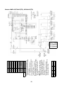
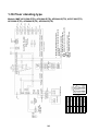
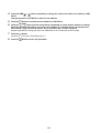
1-4. Concealed duct standard type
Models: MMD-AP0074BH-E(TR), AP0094BH-E(TR), AP0124BH-E(TR), AP0154BH-E(TR),
AP0184BH-E(TR), AP0244BH-E(TR), AP0274BH-E(TR), AP0304BH-E(TR),
AP0364BH-E(TR), AP0484BH-E(TR), AP0564BH-E(TR)
17
Parts Name
Fan motor Control Relay
Connector
Fuse
Fuse
Fan Motor
Pulse Motor Valve
Running Capacitor
Drain Control Relay
Fan Motor Control Relay
Indoor temp sensor
Terminal Block
Temp sensor
Transformer
Drain Pump Motor
Float Switch
1. Broken line indicate the wiring at site.
Long dashed short dashed line indicate
the accessories.
2.
indicates the terminal block.
indicates the connection terminal.
indicates the connector on the
control P.C. board.
3. indicates the protection ground.
4.
indicates the control P.C. board.
5. When installing the drain pump connect
the froat switch connector to CN30
connector.
6.
position is connected to terminal
block when change to static pressure.
Exchange the lead wire of arrow ( )
position after check the terminal
number as figure and lead wire's color
of fan motor.
7. Be careful when modify the static
pressure, the static pressure of high tap
is different by 50Hz or 60Hz.
Symbol
43F1,F2
CN**
F
F301
FM
PMV
RC
RY002
RY005,006,007
TA
TB01,02,03
TC1,2,TCJ
TR
DM
Sold
Separately
FS
18
Outdoor
unit
COLOR
IDENTIFICATION
RED : RED
WHI : WHITE
YEL : YELLOW
BLU : BLUE
BLK : BLACK
GRY : GRAY
PNK : PINK
ORN : ORANGE
BRW : BROWN
GRN : GREEN
Power supply
1~50Hz 220-240V
1~60Hz 220V
Indoor unit
Earth screw
Flow selector unit
Earth screw
Line Filter
Remote
Controller
Sub P.C. Board
Power
supply
circuit
Control P.C. Board
for Indoor Unit
Fan motor wiring(MMD-)
Static
AP0484
AP0184~AP0364 pressure tap
BLU(50/60Hz)
Low tap
Wired for MMD-AP0484H-E only
Brown color wire.
Motor over heating
protection switch
Fan motor inside wiring diagram (exp.)
F2
ORN(50/60Hz)
Middle tap
F3
BLK(60Hz)
BLK(50/60Hz) High tap
F4
BRW(50Hz)
—
High tap
(Refer tha static pressure specifications for each tap.)
F1
Terminal
No.
When drain
pump is installed
1-5. Concealed duct high static pressure type
Models: MMD-AP0184H-E(TR), AP0244H-E(TR), AP0274H-E(TR), AP0364H-E(TR),
AP0484H-E(TR)
Temp sensor
Transformer
Drain Pump Motor
Float Switch
Terminal Block
Parts Name
Fan motor Control Relay
Connector
Fuse for Fan Motor
Fuse
Fan Motor
Pulse Motor Valve
Running Capacitor
Drain Control Relay
Fan Motor Control Relay
Indoor temp sensor
19
Terminal Fan motor Static pressure
Note
No.
wiring
Pa (mmAq)
F1
YEL
69(7)
F2
BLU
137(14)
Setting from factory
F3
ORN
196(20)
1. Broken line indicate the wiring at site.
Long dashed short dashed line indicate
the accessories.
2.
indicates the terminal block.
indicates the connection terminal.
indicates the connector on the
control P.C. board.
3. indicates the protection ground.
4.
indicates the control P.C. board.
5. When installing the drain pump connect
the froat switch connector to CN30
connector.
6.
position is connected to terminal
block when change to static pressure.
Exchange the lead wire of arrow ( )
position after check the terminal
number as figure and lead wire's color
of fan motor.
7. Be careful when modify the static
pressure, the static pressure of high tap
is different by 50Hz or 60Hz.
Symbol
43F1,F2
CN**
F1,2,3
F301
FM
PMV
RC
RY002
RY005,006,007
TA
TB01,02,03,
04,05,06
TC1,2,TCJ
TR
DM
Sold
Separately
FS
Power supply
1~50Hz 220-240V
1~60Hz 220V
Indoor unit
Earth screw
Flow selector unit
Earth screw
COLOR
IDENTIFICATION
RED : RED
WHI : WHITE
YEL : YELLOW
BLU : BLUE
BLK : BLACK
GRY : GRAY
PNK : PINK
ORN : ORANGE
BRW : BROWN
GRN : GREEN
Outdoor
unit
Line Filter
Remote
Controller
Sub P.C. Board
Power
supply
circuit
Control P.C. Board
for Indoor Unit
Motor over heating
protection switch
Fan motor inside wiring diagram
When drain
pump is installed
Models: MMD-AP0724H-E(TR), AP0964H-E(TR)
20
Outdoor unit
Indoor unit
Earth screw
Power supply
1~50Hz 220-240V
1~60Hz 220V
Wired Remote
Controller
Flow selector unit
Earth screw
Symbol
CN**
DM
F301,302
FM
FS
RY302
TA
TB01,02
TC1,2,TCJ
Parts Name
Connector
Drain Pump Motor
Fuse
Fan Motor
Float Switch
Drain Control Relay
Indoor temp sensor
Terminal Block
Temp sensor
COLOR
IDENTIFICATION
RED : RED
WHI : WHITE
YEL : YELLOW
BLU : BLUE
BLK : BLACK
GRY : GRAY
PNK : PINK
ORN : ORANGE
BRW : BROWN
GRN : GREEN
1. Broken line indicate the wiring at site.
Long dashed short dashed line indicate the
accessories.
2.
indicates the terminal block.
indicates the connection terminal.
indicates the connector on the control P.C.
board.
3. indicates the protection ground.
4.
indicates the control P.C. board.
Control P.C. Board for
Indoor Unit
Power
supply
circuit
(High ceiling
reshuffling)
1-6. Slim duct type
Models: MMD-AP0074SPH-E(TR), AP0094SPH-E(TR), AP0124SPH-E(TR),
AP0154SPH-E(TR), AP0184SPH-E(TR)
21
Sold
Separately
Symbol
CN**
F301,302
FM
LM
PMV
RY302
TA
TB01,02
TC1,2,TCJ
DM
FS
Outdoor unit
Power supply
1~50Hz 220-240V
1~60Hz 220V
Parts Name
Connector
Fuse
Fan Motor
Louver Motor
Pulse Motor Valve
Drain Control Relay
Indoor temp sensor
Terminal Block
Temp sensor
Drain Pump Motor
Float Switch
Remote Controller
Indoor unit
Earth screw
Flow selector unit
Earth screw
COLOR
IDENTIFICATION
RED : RED
WHI : WHITE
YEL : YELLOW
BLU : BLUE
BLK : BLACK
GRY : GRAY
PNK : PINK
ORN : ORANGE
BRW : BROWN
GRN : GREEN
Adapter for Wireless
Remote Controller
1. Broken line indicate the wiring at site.
Long dashed short dashed line indicate the
accessories.
2.
indicates the terminal block.
indicates the connection terminal.
indicates the connector on the control P.C.
board.
3. indicates the protection ground.
4.
indicates the control P.C. board.
5. When installing the drain pump connect the froat
switch connector to CN34 connector.
Power
supply
circuit
Control P.C. Board for
Indoor Unit
(High ceiling
reshuffling)
When drain
pump is installed
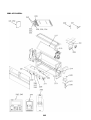
1-7. Ceiling type
Models: MMC-AP0154H-E(TR), AP0184H-E(TR), AP0244H-E(TR), AP0274H-E(TR),
AP0364H-E(TR), AP0484H-E(TR)
Symbol
Parts Name
CN**
Connector
F301
Fuse
FM
Fan Motor
PMV
Pulse Motor Valve
RC
Running Capacitor
RY005,006,007 Fan Motor Control Relay
TA
Indoor temp sensor
TB01,02
Terminal Block
TC1,2,TCJ
Temp sensor
TR
Transformer
COLOR
IDENTIFICATION
RED : RED
WHI : WHITE
YEL : YELLOW
BLU : BLUE
BLK : BLACK
GRY : GRAY
PNK : PINK
ORN : ORANGE
BRW : BROWN
GRN : GREEN
22
Outdoor unit
Line Filter
Power supply
1~50Hz 220-240V
1~60Hz 220V
Indoor unit
Earth screw
Flow selector unit
Earth screw
Remote Controller
Sub P.C. Board
Power
supply
circuit
1. Broken line indicate the wiring at site.
Long dashed short dashed line indicate the
accessories.
2.
indicates the terminal block.
indicates the connection terminal.
indicates the connector on the control P.C.
board.
3. indicates the protection ground.
4.
indicates the control P.C. board.
Control P.C. Board for
Indoor Unit
1-8. Floor standing cabinet type
Models: MML-AP0074H-E(TR), AP0094H-E(TR), AP0124H-E(TR), AP0154H-E(TR),
AP0184H-E(TR), AP0244H-E(TR)
23
Outdoor unit
Line Filter
COLOR
IDENTIFICATION
RED : RED
WHI : WHITE
YEL : YELLOW
BLU : BLUE
BLK : BLACK
GRY : GRAY
PNK : PINK
ORN : ORANGE
BRW : BROWN
GRN : GREEN
Remote Controller
Symbol
Parts Name
CN**
Connector
F301
Fuse
FM
Fan Motor
PMV
Pulse Motor Valve
RC
Running Capacitor
RY005,006,007 Fan Motor Control Relay
TA
Indoor temp sensor
TB01,02,03
Terminal Block
TC1,2,TCJ
Temp sensor
TR
Transformer
Power supply
Indoor unit
Earth screw 1~50Hz 220-240V
1~60Hz 220V
Flow selector unit
Earth screw
Sub P.C. Board
Power
supply
circuit
1. Broken line indicate the wiring at site.
Long dashed short dashed line indicate the
accessories.
2.
indicates the terminal block.
indicates the connection terminal.
indicates the connector on the control P.C.
board.
3. indicates the protection ground.
4.
indicates the control P.C. board.
Control P.C. Board for
Indoor Unit
1-9. Floor standing concealed type
Models: MML-AP0074BH-E(TR), AP0094BH-E(TR), AP0124BH-E(TR), AP0154BH-E(TR),
AP0184BH-E(TR), AP0244BH-E(TR)
24
Outdoor unit
Line Filter
Flow selector
unit Earth
screw
COLOR
IDENTIFICATION
RED : RED
WHI : WHITE
YEL : YELLOW
BLU : BLUE
BLK : BLACK
GRY : GRAY
PNK : PINK
ORN : ORANGE
BRW : BROWN
GRN : GREEN
Remote Controller
Symbol
Parts Name
CN**
Connector
LM
Louver Motor
F301
Fuse
FM
Fan Motor
PMV
Pulse Motor Valve
RC
Running Capacitor
RY001
Louver Control Relay
RY005,006,007 Fan Motor Control Relay
TA
Indoor temp sensor
TB01,02,03
Terminal Block
TC1,2,TCJ
Temp sensor
TR
Transformer
Power supply
1~50Hz 220-240V
1~60Hz 220V
Indoor unit
Earth screw
Sub P.C. Board
Power
supply
circuit
1. Broken line indicate the wiring at site.
Long dashed short dashed line indicate the
accessories.
2.
indicates the terminal block.
indicates the connection terminal.
indicates the connector on the control P.C.
board.
3. indicates the protection ground.
4.
indicates the control P.C. board.
Control P.C. Board for
Indoor Unit
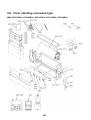
1-10.Floor standing type
Models: MMF-AP0154H-E(TR), AP0184H-E(TR), AP0244H-E(TR), AP0274H-E(TR),
AP0364H-E(TR), AP0484H-E(TR), AP0564H-E(TR)
2
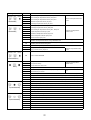
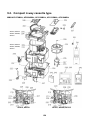
Parts Rating
2-1. Indoor unit
Compact 4-way cassette type
Model
MMU-AP
0074MH
0094MH
0124MH
Fan motor
0154MH
0184MH
SWF-230-60-1R
Motor for horizontal grille
MP24Z3N
Pulse motor
EDM-MD12TF-3
Pulse motor valve
EDM-B25YGTF-3
TA sensor
EDM-B40YGTF-3
Lead wire length: 155 mm Vinyl tube
TC1 sensor
Ø4 size lead wire length: 1400 mm Vinyl tube
TC2 sensor
Ø6 size lead wire length: 1500 mm Vinyl tube (Black)
TCJ sensor
Ø6 size lead wire length: 1400 mm Vinyl tube (Red)
Float switch
FS-0218-103
Drain pump motor
ADP-1409
1-way cassette type
Model
MMU-AP
0074YH
0094YH
Fan motor
AF-200-22-4N-1
Running capacitor for fan motor
AC 400 V, 1 µF
Drain pump motor
PJD-05230TF-1
Float switch
FS-0208-602
Control P.C. board transformer
TT-13
Pulse motor
EDM-MD12TF-3
Pulse motor valve
EDM-B25YGTF
TA sensor
Lead wire length: 818 mm
TC1 sensor
Ø4 size lead wire length: 1200 mm Vinyl tube (Blue)
TCJ sensor
Ø6 size lead wire length: 1200 mm Vinyl tube (Red)
Model
MMU-AP
0154SH
0184SH
Fan motor
SWF-280-60-1
Driving motor for horizontal grille
MP24GA1
Pulse motor
EDM-MD12TF-3
Pulse motor valve
TA sensor
0124YH
EDM-B40YGTF-3
Lead wire length: 155 mm Vinyl tube
TC1 sensor
Ø4 size lead wire length: 1100 mm Vinyl tube (Blue)
TC2 sensor
Ø6 size lead wire length: 1100 mm Vinyl tube (Black)
TCJ sensor
Ø6 size lead wire length: 1100 mm Vinyl tube (Red)
Float switch
FS-0218-103
Drain pump motor
ADP-1409
25
0244SH
Concealed duct standard type
Model
MMD-AP
0074BH
0094BH
0124BH
Fan motor
0154BH
ICF-280-120-2
Drain pump motor
ADP-1409
Float switch
FS-0218-102
Pulse motor
EDM-MD12TF-3
Pulse motor valve
EDM-B25YGTF
TA sensor
EDM-B40YGTF
Lead wire length: 618 mm
TC1 sensor
Ø4 size lead wire length: 1200 mm Vinyl tube (Blue)
TC2 sensor
Ø6 size lead wire length: 1200 mm Vinyl tube (Black)
TCJ sensor
Ø6 size lead wire length: 1200 mm Vinyl tube (Red)
Model
0184BH
MMD-AP
0244BH
Fan motor
0274BH
0304BH
0364BH
ICF-280-120-1
0484BH
0564BH
ICF-280-120-2
Drain pump motor
ADP-1409
Float switch
FS-0218-102
Pulse motor
EDM-MD12TF-3
Pulse motor valve
EDM-B40YGTF
TA sensor
EDM-B60YGTF-1
Lead wire length: 618 mm
TC1 sensor
Ø4 size lead wire length: 1200 mm Vinyl tube (Blue)
TC2 sensor
Ø6 size lead wire length: 1200 mm Vinyl tube (Black)
TCJ sensor
Ø6 size lead wire length: 1200 mm Vinyl tube (Red)
Concealed duct high static pressure type
Model
MMD-AP
Fan motor
Running condenser for fan motor
0184H
0244H
0274H
0364H
0484H
STF-200-160-4B
STF-200-160-4A
STF-200-260-4C
STF-200-260-4B
AC 500 V, 4 µF
AC 400 V, 8 µF
AC 450 V, 6 µF
AC 400 V, 8 µF
Drain pump motor
ADP-1409
Float switch
FS-0218-102-6
Pulse motor
EDM-MD12TF-3
Pulse motor valve
EDM-B40YGTF
TA sensor
EDM-B60YGTF-1
Lead wire length: 1200 mm
TC1 sensor
Ø4 size lead wire length: 1200 mm Vinyl tube (Blue)
TC2 sensor
Ø6 size lead wire length: 1200 mm Vinyl tube (Black)
TCJ sensor
Ø6 size lead wire length: 1200 mm Vinyl tube (Red)
Model
MMD-AP
0724H
0964H
Fan motor
STF-200-370-4A
Running condenser for fan motor
AC 450 V, 12 µF
Drain pump motor
ADP-1409
Float switch
FS-0218-102-6
Pulse motor
EDM-MD12TF-3
Pulse motor valve
EDM-BAOYGTF-1
TA sensor
Lead wire length: 818 mm
TC1 sensor
Ø4 size lead wire length: 2000 mm Vinyl tube (Blue)
TC2 sensor
Ø6 size lead wire length: 2000 mm Vinyl tube (Black)
TCJ sensor
Ø6 size lead wire length: 2000 mm Vinyl tube (Red)
26
Slim duct type
Model
MMD-AP
0074SPH
0094SPH
0124SPH
Fan motor
0154SPH
0184SPH
SWF-280-60-1
Pulse motor
EDM-MD12TF-3
Pulse motor valve
EDM-B25YGTF
Drain pump motor
EDM-B40YGTF
ADP-1409
Float switch
FS-0218-102
TA sensor
Lead wire length: 1558 mm Vinyl tube
TC1 sensor
Ø4 size lead wire length: 1200 mm Vinyl tube (Blue)
TC2 sensor
Ø6 size lead wire length: 1200 mm Vinyl tube (Black)
TCJ sensor
Ø6 size lead wire length: 1200 mm Vinyl tube (Red)
Ceiling type
Model
MMC-AP
0154H
Fan motor
0184H
0244H
SWF-280-60-1
0274H
0364H
SWF-280-60-2
Driving motor for horizontal grille
0484H
SWF-280-120-2
MP24GA1
Pulse motor
EDM-MD12TF-3
Pulse motor valve
EDM-B40YGTF
TA sensor
EDM-B60YGTF-1
Lead wire length: 155 mm Vinyl tube
TC1 sensor
Ø4 size lead wire length: 1200 mm Vinyl tube (Blue)
TC2 sensor
Ø6 size lead wire length: 1200 mm Vinyl tube (Black)
TCJ sensor
Ø6 size lead wire length: 1200 mm Vinyl tube (Red)
Floor standing cabinet type
Model
MML-AP
Fan motor
Running condenser for fan motor
0074H
0094H
0124H
0154H
0244H
AF-200-19-4F
AF-200-45-4F
AF200-70-4K
AC450 V, 1.2 µF
AC400 V, 1.8 µF
AC450 V, 2 µF
Transformer
TT13
Pulse motor
EDM-MD12TF-3
Pulse motor valve
0184H
EDM-B25YGTF
TA sensor
EDM-B40YGTF
Lead wire length: 818 mm Vinyl tube
TC1 sensor
Ø4 size lead wire length: 1200 mm Vinyl tube (Blue)
TC2 sensor
Ø6 size lead wire length: 1200 mm Vinyl tube (Black)
TCJ sensor
Ø6 size lead wire length: 1200 mm Vinyl tube (Red)
Floor standing concealed type
Model
MML-AP
Fan motor
Running condenser for fan motor
0074BH
0094BH
0124BH
0154BH
AF-200-19-4G
AC450 V, 1 µF
TT-13
Pulse motor
EDM-MD12TF-3
TA sensor
EDM-B25YGTF
EDM-B40YGTF
Lead wire length: 818 mm Vinyl tube
TC1 sensor
Ø4 size lead wire length: 2000 mm Vinyl tube (Blue)
TC2 sensor
Ø6 size lead wire length: 2000 mm Vinyl tube (Black)
TCJ sensor
Ø6 size lead wire length: 2000 mm Vinyl tube (Red)
27
0244BH
AF-200-70-4K
AC450 V, 1.5 µF
Transformer
Pulse motor valve
0184BH
AC450 V, 2 µF
Floor standing type
Model
MMF-AP
Fan motor
Running condenser for fan motor
0154H
0184H
0244H
0274H
AF-200-37R
AF-200-63T
AC500 V, 3 µF
AC500 V, 3.5 µF
0364H
AF-200-110M-1
Transformer
TT-13
Pulse motor
EDM-MD12TF-3
Pulse motor valve
EDM-B40YGTF
Driving motor for vertical louver
TA sensor
0484H
EDM-B60YGTF-1
MT8-3-9
TC1 sensor
Ø4 size lead wire length: 1200 mm Vinyl tube (Blue)
TC2 sensor
Ø6 size lead wire length: 2000 mm Vinyl tube (Black)
TCJ sensor
Ø6 size lead wire length: 1200 mm Vinyl tube (Red)
28
AF-200-160H-1
AC500 V, 4 µF
Lead wire length: 1200 mm Vinyl tube
0564H
3
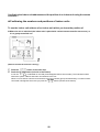
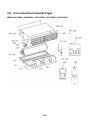
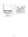
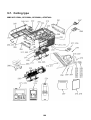
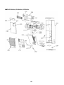
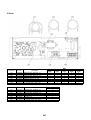
Refrigerant Cycle Diagram
Indoor unit
Liquid
side
Gas side
Strainer
Capillary tube
Heat exchanger at
indoor side
Pulse Motor
Valve (PMV)
Sensor
(TC2)
Sensor
(TCJ)
Fan
Sensor
(TC1)
Sensor
(TA)
Fan motor
CAUTION
MMU-AP0074YH, AP0094YH, AP0124YH type air conditioners have no TC2 sensor.
Explanation of functional parts in indoor unit
Functional part name
Pulse Motor Valve
Temp. Sensor
Functional outline
PMV
(Connector CN082 (6P): Blue)
1) Controls super heat in cooling operation
2) Controls under cool in heating operation
3) Recovers refrigerant oil in cooling operation
4) Recovers refrigerant oil in heating operation
1.TA
(Connector CN104 (2P): Yellow)
1) Detects indoor suction temperature
2.TC1
(Connector CN100 (3P): Brown)
1) Controls PMV super heat in cooling operation
3.TC2
(Connector CN101 (2P): Black)
1) Controls PMV under cool in heating operation
4.TCJ
(Connector CN102 (2P): Red)
1) Controls PMV super heat in cooling operation
2) [MMU-AP0074YH to AP0124YH only] Controls PMV under cool in heating operation
29
4
Control Outline
Indoor unit
Control specifications
NO.
Item
Specification outline
Remarks
Upon power
supply reset
1. Identification of outdoor unit
When the power supply is reset, the outdoor unit is identified, and control is
redirected according to the identification result.
2. Indoor fan speed and air flow direction control availability settings
Settings such as indoor fan speed and air flow direction control availability are
replaced on the basis of EEPROM data.
3. If power supply reset is performed in the wake of a fault, the check code is cleared.
If the abnormality persists after the Start / Stop button on the remote controller is
pressed to resume operation, the check code is redisplayed on the remote
controller.
Operation
selection
1. The operation mode changes in response to an operation selection command
issued via the remote controller.
1
Remote controller command
STOP
2
Control outline
Air conditioner shutdown
FAN
Room temp.
control
Ts: Temperature
setting
Ta: Room temperature
Fan operation
COOL
Cooling operation
DRY
Drying operation
HEAT
Heating operation
1. Adjustment range - remote controller temperature setting (°C)
COOL / DRY
HEAT
Wired type
18~29
18~29
Wireless type
18~30
16~30
Shift in heating suction
temperature
(not applicable to
remote controller
thermo operation)
2. In heating operation, the temperature setting may be fine-tuned via the DN code
“06”.
3
SET DATA
Temperature setting adjustment
0
2
4
6
+0 °C
+2 °C
+4 °C
+6 °C
Factory default
Automatic
capacity control
Model type
SET DATA
Floor standing (standard, concealed, cabinet)
0
Other model
2
1. The outdoor unit determines the operational capacities of indoor units according
to the difference between Ta and Ts.
Cooling
Heating
4
30
Ts: Temperature
setting
Ta: Room temperature
NO.
Item
Fan speed
control
5
Specification outline
1. The fan operates in one of the four speed modes of “HIGH (HH)”, “MED (H)”,
“LOW (L)” and “AUTO” on the basis of a command issued via the remote
controller. (Concealed duct high static pressure type: HH only)
2. In AUTO fan speed mode, the air speed changes according to the difference
between Ta and Ts.
<Cooling>
• Control is identical in remote controller thermo and body thermo operation.
Speed modes shown in < > apply to cooling operation under AUTO air
conditioner operation mode.
• In AUTO fan speed mode, the fan speed remains the same for 3 minutes each
time a speed change occurs.
However, a speed change command issued via the remote controller can
override this, and the fan speed changes accordingly.
• At the beginning of cooling operation, a higher speed (steeper downward
temperature gradient) is chosen.
• As long as the temperature difference remains on a boundary line, the fan speed
stays the same.
<Heating>
Remarks
HH > H+ > H >
L+ > L > UL
or LL
DN code “32”
“0000”: Body thermo
“0001”: Remote
controller thermo
Figures inside ( ) applies to remote controller thermo operation.
Figures outside ( ) applies to body thermo operation.
Speed modes shown in < > apply to heating operation under AUTO air
conditioner operation mode.
• In AUTO fan speed mode, the fan speed remains the same for 1 minute each TC2: Indoor heat
exchanger sensor
time a speed change occurs.
temperature
However, a speed change command issued via the remote controller can
override this, and the fan speed changes accordingly.
• At the beginning of heating operation, a higher speed (steeper upward
temperature gradient) is chosen.
• As long as the temperature difference remains on a boundary line, the fan speed
stays the same.
• When TC2 60 °C, the fan speed is raised by one step.
3. If the air conditioner goes thermo OFF during heating operation, the fan speed
drops down to LL (breeze).
31
“HEATING
STANDBY
displayed
”
NO.
Item
Cold air
discharge
prevention
control
Specification outline
Zone A:OFF
Zone B:26 °C or above and
below 28 °C
Breeze
Zone C:28 °C or above and
below 30 °C
Low
Zone D:30 °C or above and
below 32 °C
Medium
Zone E:High
6
Freeze
prevention
control (low
temp. release)
7
Remarks
1. In heating operation, the upper limit of the fan tap is set according to the lower of
whichever is the higher between TC2 sensor and TCJ sensor temperatures, on
the one hand, and TC1 sensor temperature, on the other.
• If the fan continuously operates in zone B for 6 minutes, it automatically moves
into zone C.
• During defrosting, the control point is shifted by +6 °C.
TCJ: Indoor heat
exchanger sensor
temperature
• In zones D and E,
priority is given to the
remote controller fan
speed setting.
• In zone A, “HEATING
STANDBY
” is
displayed.
TC1: Indoor heat
1. During cooling, the air conditioner is operated in the manner described below
exchanger sensor
according to the temperature readings of the TC1, TC2 and TCJ sensors.
temperature
• If zone J operation is detected for 5 minutes, the air conditioner is forced into
thermo OFF.
• In zone K, the timer is put on pause, with the current timer count retained.
• If zone I operation is detected, the timer count is cleared, and the air conditioner
returns to normal operation.
• If continuous zone J operation forces the air conditioner into thermo OFF, the
indoor fan is operated in breeze mode until it moves into zone I.
The control is terminated under the following conditions:
Termination conditions
1) TC1 12 °C, TC2 12 °C, and TCJ 12 °C
2) Passage of 20 minutes after stoppage
TC1
TC2, TCJ
P1
10 °C (5 °C)
-10 °C
Q1
0 °C
-14 °C
Temperature in ( ): If the temperature is below
this value when the power is turned on, the air
conditioner is forced into thermo OFF.
2. During cooling, the air conditioner is operated in the manner described below
according to the temperature readings of the TC2 and TCJ sensors.
• If zone M operation is detected for 45 minutes, the air conditioner is forced into
thermo OFF.
• In zone N, the timer is put on pause, with the current timer count retained.
• When the air conditioner goes back into zone M, timer count is resumed from
the retained value.
• If zone L operation is detected, the timer count is cleared, and the air conditioner
returns to normal operation.
TC2, TCJ
P2
5
Q2
-2.0
Reset conditions
1) TC1 12 °C, TC2 12 °C and TCJ 12 °C
2) Passage of 20 minutes after stoppage
32
* With models without
TC2, TC2 is not part
of the control
parameters.
NO.
Item
Specification outline
Remarks
8
Cooling oil
While the outdoor unit is recovering cooling oil (refrigerant), the indoor units perform • Recovery operation
normally takes place
(refrigerant)
the following control tasks:
roughly every 2 hours.
recovery control [common for operational (cooling thermo ON / thermo OFF / FAN), as well as non• The opening position
operational indoor units]
of the indoor PMV
1) Open the indoor PMV to a certain degree.
depending on the type
2) Engage in recovery control for a specified period of time and return to normal
and capacity of the
indoor unit.
cooling operation at the end of this period upon terminating the control.
3) Operate the drain pump throughout the recovery control period and for about 1
minute after it.
9
Heating
While the outdoor unit is recovering heating refrigerant (oil), the indoor units perform • Recovery operation
normally takes place
refrigerant (oil)
the following control tasks:
roughly every hour.
recovery control
1) Open the indoor PMV to a certain degree.
• The opening position
2) Control the indoor fan according to the operation mode.
of the indoor PMV
[Indoor units operating in heating thermo ON / OFF state]
depending on the type
Let the indoor fan continue operating, but turn it off if the temperature of the indoor
and capacity of the
indoor unit.
heat exchanger drops.
[Indoor units operating in FAN mode]
Turn off the indoor fan and display “HEATING STANDBY ” on the remote
controller.
[Non-operational indoor units]
Keep the indoor fan turned off.
3) Terminate the recovery operation depending on the TC2 temperature reading.
The timing of termination is determined by each indoor unit.
4) Operate the indoor fan and drain pump for about 1 minute after the termination
of the recovery operation. (Applicable to compact 4-way cassette type and 1way cassette type)
Defrosting
control
While the outdoor unit is engaged in defrosting control, the indoor units perform the • For defrosting
commencement
following control tasks:
conditions, see 5
1) Open the indoor PMV to a certain degree.
Control Outline “7.
2) Control the indoor fan according to the operation mode.
Defrosting control
[Indoor units operating in heating thermo ON / OFF state]
(reverse defrosting
Let the indoor fan continue operating for a while, but turn it off as the temperature
method)” in SMMS-i
Outdoor Unit Service
of the indoor heat exchanger drops.
Manual A10-005
[Indoor units operating in FAN mode]
above.
Let the indoor fan continue operating.
• The opening position
[Non-operational indoor units]
of the indoor PMV
Keep the indoor fan turned off.
depending on the type
3) As defrosting control comes to an end, it gives way to heating refrigerant (oil)
and capacity of the
indoor unit.
recovery control.
(For control details, see “9. Heating refrigerant (oil) recovery control” above.)
Short
intermittent
operation
compensation
control
1. For 5 minutes after startup, the system is forced to continue operating even if it
reaches the thermo OFF region.
2. However, priority is given to cooling / heating selection, operation standby, and
protective control, so that there is no overriding of thermo OFF in these cases.
Drain pump
control
1. During cooling (including DRY operation), the drain pump is operated at all times. Check code [P10]
2. If the float switch is activated while the drain pump is in operation, the drain pump
continues operating, with the relevant check code displayed.
3. If the float switch is activated while the drain pump is turned off, thermo OFF is
forced on the air conditioner, with the drain pump put into operation. If the float
switch continues to be activated for about 5 minutes, the drain pump is turned off,
with the relevant check code displayed.
Elimination of
residual heat
1. When the air conditioner is turned off after engaging in heating operation, the
indoor fan is operated for about 30 seconds in “breeze” mode.
10
11
12
13
33
NO.
Item
Specification outline
Remarks
“FILTER
1. The indoor fan’s cumulative hours of operation are counted, and when these
Filter sign
exceed the prescribed value (150H / 2500H), a filter replacement signal is sent to
display
the remote controller to display a filter sign on it.
(not applicable
to wireless type) 2. When a filter reset signal is received from the remote controller, the timer
* Provided in
measuring cumulative hours is cleared. If the prescribed hours have been
the separately
exceeded, the hours count is reset, with the sign on the remote controller display
mounted type,
erased.
TCB-AX21E.
14
Filter service life
Type
15
2500H
4-way cassette type
1-way cassette type
(SH, YH)
2-way cassette type
Ceiling type
Concealed duct standard type
Concealed duct high static
pressure type
Slim duct type
” displayed
150H
High wall type
Floor standing type
Floor standing concealed
type
Floor standing cabinet type
• “OPERATION
Operation
<Operation standby> .......... Displayed on remote controller
STANDBY
”
standby
1. When any of the DN codes listed below is displayed
displayed
Heating standby
• “P05” - Detection of an open phase in the power supply wiring
• “P10” - Detection of indoor flooding in at least one indoor unit
No display provided
• “L30” - Detection of an interlock alarm in at least one indoor unit
on wireless remote
controller
2. Forced thermo OFF
• “COOL / DRY” operation is unavailable because at least one indoor unit is
operating in “HEAT” mode.
• “HEAT” operation is unavailable because at least one indoor unit is operating in
“COOL / DRY” mode under priority cooling setting (bit 1 of SW11 on outdoor I/
F P.C. board ON).
3. All indoor units not able to engage in any of the above operations stand by in
thermo OFF state.
4. The indoor fan has been turned off because the system is engaged in a heat
refrigerant (oil) recovery operation.
• “HEATING
<Heating standby> .......... Displayed on remote controller
STANDBY
1. Normal thermo OFF
displayed
• During heating, the indoor unit goes thermo OFF as the heating temperature
setting is reached.
2. During heating, the fan rotates at a breeze speed (UL or lower) or remains
stationary to prevent cold air from being discharged (including defrosting
operation).
3. Forced thermo OFF
• “HEAT” operation is unavailable because at least one indoor unit is operating in
“COOL / DRY” mode under priority cooling setting (bit 1 of SW11 on outdoor I/
F P.C. board ON).
34
”
NO.
Item
Selection of
central control
mode
Specification outline
Remarks
1. The range of operations that can be performed via an indoor unit remote controller • In the case of a wired
remote controller,
can be determined through the setting of the central controller.
“CENTRAL
2. Setting details
CONTROL IN
TCC-Link central control
16
Operation via RBC-AMT32E
Operation
via TCCLink central
control
Start / stop
selection
Individual
Central 1
Operation
mode
selection
Timer
setting
O
O
O
O
O
O
u
O
u
O
O
O
Central 2
u
u
u
u
O
O
Central 3
O
u
O
u
O
O
Central 4
O
u
O
O
O
O
(O: Accessible
Louver control
Temperature
setting
Fan speed
setting
RBCAMT32E
display
Air flow
direction
setting
“CENTRAL
CONTROL
IN
PROGRESS”
u: Inaccessible)
PROGRESS
” is
displayed (lit up) while
in central control
mode.
• The display blinks
when a control
function inaccessible
to a remote controller
is chosen.
• A wireless remote
controller has the
same set of control
functions, although
there is no display.
When a control
operation is
performed via a
wireless remote
controller while in
central control mode,
a peep sound alert (5
times) is provided.
1. Louver position setting
• When the louver position is changed, the louver turns all the way down before
settling in the set position.
• Louver position is adjustable in the range shown in the diagrams below.
During cooling / drying
During heating / fan-only operation
• During group operation, position setting can be performed individually or
collectively.
2. Swing setting
• The “SWING” sign is displayed, along with alternating images as shown below.
In all operation modes
17
(alternating)
• During group operation, swing setting can be performed individually or
collectively.
3. Set louver positions
DC motor
18
4-way
1-way (SH)
Ceiling
Normal stop
Downward
Closed
Horizontal
Abnormal stop
Downward
No change
Horizontal
Heating standby
Upward
Upward
Horizontal
Oil / refrigerant recovery
Upward
Upward
Horizontal
1. When the fan is turned on, the positions of the stator and rotor are determined.
(The motor turns in incremental steps.)
2. The fan operates in accordance with commands issued by the indoor controller.
Note:
If the fan is rotating while the air conditioner is turned off due to an inflow of outside
air or some other reason, the indoor unit may operate without turning on the fan
motor.
Note:
If fan motor lock is detected, the indoor unit is turned off, with an error display
provided.
35
Check code “P12”
NO.
Item
Power saving
mode
19
Specification outline
Remarks
1. Push the
button on the remote controller
2. The " " segment lights up on the wired remote controller display.
3. The requirement capacity ratio is limited to approximately 75 %.
4. If the power saving operation is enabled, the settings are retained when the
operation is stopped, when the mode is changed, or when the power is reset. The
power saving operation will be enabled the next time the operation starts.
The power saving
operation cannot be
set by the wireless
remote controller or
wired remote
controller of AMT31E
or older.
36
37
(In case
of 1:1
model)
Central
remote
controller
(optional)
Louver
motor
Switch setting
Power supply circuit
Fan motor
control circuit
CPU
Power
source
Power source
1Ø 220-240 V, 50 Hz
1Ø 220 V, 60 Hz
Outdoor
unit
Outdoor
unit
Power
source
Outdoor
unit
*3 A weekly timer cannot be
connected to a sub remote
controller.
*2 The network adaptor can only
be installed in one unit.
*1 Only up to 7 units if a network
adaptor is installed with 2
main (sub) remote controllers
connected.
Up to 8 units can be connected.
*1
Key switch
Function setting
Sameas left
*2
Rechargeable
battery
LCD
driver
Sameas left
*2
Power
supply
circuit
Display
LCD
Schedule Timer (Weekly timer mode)
Indoor / outdoor communication
Float input
TCJ sensor
TC2 sensor
TCI sensor
TA sensor
EEPROM
Power
supply
circuit
Key switch
Function setting
AC
BUS
In operation
synchronization communication
Alarm
circuit
Getting ready signal input circuit
Thermostat ON
COOL
HEAT
FAN
External output
Remote
controller
communication
circuit
Remote controller
communication circuit
EEPROM
Display
LED
Indoor control P.C. board (MCC-1402)
Network adaptor : "1:1 model" connection interface
TCB-PCNT30TLE2
Indoor
fan
motor
Drain
pump
*Not applicable to concealed duct
standard type Slim Duct Type
Transformer
Power supply circuit
AI-NET
communication
circuit
Network
adaptor P.C. Remote controller
communication
board
circuit
(MCC-1401)
Network adaptor (optional)
Indoor unit
Sub remote controller
:RBC-AS21E2
Main remote controller
:RBC-AMT32E
Display
LCD
Main (sub) remote controller (up to 2 units)
Driver
5
Applied Control and Functions
(Including Circuit Configuration)
5-1. Indoor controller block diagram
5-1-1. When main (sub) remote controller connected
<Compact 4-way cassette type, 1-way cassette (SH) type, ceiling type, concealed duct
standard type, slim duct type>
38
(In case
of 1:1
model)
Central
remote
controller
(optional)
Drain
pump
Louver
motor
Fan motor
relay circuit
Transformer
Power supply circuit
*Not applicable to concealed
duct high static pressure type
Power
source
Outdoor
unit
Power
source
Outdoor
unit
*3 A weekly timer cannot be
connected to a sub
remote controller.
*2 The network adaptor can
only be installed in one
unit.
*1 Only up to 7 units if a
network adaptor is
installed with 2 main
(sub) remote controllers
connected.
Up to 8 units can be
connected. *1
Key switch
Function setting
Sameas left
*2
Rechargeable
battery
LCD
driver
Sameas left
*2
Power
supply
circuit
Display
LCD
Schedule Timer (Weekly timer mode)
Indoor / outdoor communication
Outdoor
unit
Power source
1Ø 220-240 V, 50 Hz
1Ø 220 V, 60 Hz
Float input
TCJ sensor
*Not applicable to 1-way
air discharge cassette
type (compact)
TC2 sensor
TCI sensor
TA sensor
EEPROM
Power
supply
circuit
Key switch
Function setting
In operation
AC
BUS
synchronization communication
Alarm
circuit
Getting ready signal input circuit
Thermostat ON
COOL
HEAT
FAN
External
output
Remote
controller
communication
circuit
Remote controller
communication circuit
EEPROM
Indoor control P.C. board (MCC-1403)
Network adaptor : "1:1 model" connection interface
TCB-PCNT30TLE2
Indoor
fan
motor
*Not applicable to
concealed duct high
static pressure type
*1-way Type
only
Transformer
Power supply circuit Switch setting
AI-NET
communication
circuit
Network
adaptor P.C. Remote controller
communication
board
circuit
(MCC-1401)
Network adaptor (optional)
Indoor unit
Sub remote controller
:RBC-AS21E2
Display
LED
Driver
Main remote controller
:RBC-AMT32E
Display
LCD
Main (sub) remote controller (up to 2 units)
<1-way cassette (YH) type, floor standing type, concealed duct high static pressure type,
floor standing concealed type, floor standing cabinet type>
(In case
of 1:1
model)
Central
remote
controller
(optional)
39
Power supply circuit
Fan motor
relay circuit
TCJ sensor
TC2 sensor
TCI sensor
TA sensor
EEPROM
Float input
*Not applicable to concealed
duct high static pressure type
Outdoor
Wireless remote controller kit
Sensor circuit
Buzzer
Display LED
Function
setting SW
Sensor P.C. board
Remote controller Emergency
communication operation SW
Power supply
circuit
circuit
Indoor / outdoor communication
BUS
communication
circuit
Remote
controller
communication
circuit
AC
synchronization
signal input circuit
Driver
unit
Power source
1Ø 220-240 V, 50 Hz
1Ø 220 V, 60 Hz
In operation
Alarm
Getting ready
Thermostat ON
COOL
HEAT
FAN
External
output
Indoor control P.C. board (MCC-1402)
Network adaptor : "1:1 model" connection interface
TCB-PCNT30TLE2
Indoor
fan
motor
Drain
pump
Louver
motor
*Not applicable to concealed duct
standard type Slim Duct Type
Transformer
Power supply circuit Switch setting
AI-NET
communication
circuit
Network
Remote controller
adaptor P.C.
communication
board
circuit
(MCC-1401)
Network adaptor (optional)
Indoor unit
Sameas left
*2
Power
Power
source
source
Outdoor
Outdoor
unit
unit
Sameas left
*2
*2 The network adaptor
can only be installed in
one unit.
*1 Only up to 7 units if a
network adaptor is
installed with 2
wireless remote
controller kits
connected.
Up to 8 units can be
connected. *1
5-1-2. When wireless remote controller kit connected
<Compact 4-way cassette type, 1-way cassette (SH) type, ceiling type, concealed duct
standard type, slim duct type>
(In case
of 1:1
model)
Central
remote
controller
(optional)
40
Indoor
fan
motor
Drain
pump
Fan motor
relay circuit
Transformer
Power supply circuit
Driver
Wireless remote controller kit
Sensor
circuit
Display
section
Remote controller
communication
circuit
Indoor / outdoor communication
Outdoor
unit
Power source
1Ø 220-240 V, 50 Hz
1Ø 220 V, 60 Hz
TCJ sensor
TC2 sensor
TCI sensor
TA sensor
EEPROM
Float input
*Not applicable to concealed
duct high static pressure type
BUS
communication
circuit
Remote
controller
communication
circuit
In operation
AC
Alarm
synchronization
Getting ready signal input circuit
Thermostat ON
COOL
HEAT
FAN
External
output
Indoor control P.C. board (MCC-1403)
Network adaptor : "1:1 model" connection interface
TCB-PCNT30TLE2
*Not applicable to
concealed duct
high static
pressure type
Louver
motor
*1-way Type only
Transformer
Power supply circuit Switch setting
AI-NET
communication
circuit
Network
adaptor P.C. Remote controller
communication
board
circuit
(MCC-1401)
Network adaptor (optional)
Indoor unit
Sameas left
*2
Power
Power
source
source
Outdoor
Outdoor
unit
unit
Sameas left
*2
*2 The network adaptor
can only be installed in
one unit.
*1 Only up to 7 units if a
network adaptor is
installed with 2
wireless remote
controller kits
connected.
Up to 8 units can be
connected. *1
<1-way cassette (YH) type, floor standing type, concealed duct high static pressure type,
floor standing concealed type, floor standing cabinet type>
41
(In case
of 1:1
model)
Central
remote
controller
(optional)
Power supply circuit
Fan motor
control circuit
AC
Power source
1Ø 220-240 V, 50 Hz
1Ø 220 V, 60 Hz
In operation
synchronization
Alarm
signal input circuit
Getting ready
Thermostat ON
COOL
HEAT
FAN
External output
*Not applicable to concealed
duct high static pressure type
Float input
TCJ sensor
TC2 sensor
TCI sensor
TA sensor
EEPROM
Power
supply
circuit
Sensor circuit
Buzzer
Indoor / outdoor communication
Outdoor
unit
Rechargeable
battery
Display LED
Function
setting SW
Wireless remote controller kit
Sensor P.C. board
Remote controller
Emergency
communication
operation SW
circuit
Power supply
circuit
Power
supply
circuit
Key switch
Key switch
LCD
driver
Function setting
Display
LCD
Schedule Timer (Weekly timer mode)
Function setting
BUS
communication
circuit
Remote
controller
communication
circuit
Remote controller
communication circuit
EEPROM
Indoor control P.C. board (MCC-1402)
Network adaptor : "1:1 model" connection interface
TCB-PCNT30TLE2
Indoor
fan
motor
Drain
pump
Louver
motor
*Not applicable to concealed duct
standard type Slim Duct Type
Transformer
Power supply circuit Switch setting
AI-NET
communication
circuit
Network
adaptor P.C. Remote controller
communication
board
circuit
(MCC-1401)
Network adaptor (optional)
Indoor unit
Sub remote controller
:RBC-AS21E2
Display
LED
Driver
Main remote controller
:RBC-AMT32E
Display
LCD
Main (sub) remote controller (up to 2 units)
Sameas left
*2
*3 A weekly timer
cannot be
connected to a
sub remote
controller.
Power
Power
source
source
Outdoor
Outdoor
unit
unit
Sameas left
*2
*2 The network
adaptor can only
be installed in
one unit.
*1 Only up to 7 units
if a network
adaptor is
installed.
Up to 8 units can be
connected. *1
5-1-3. When both main (sub) remote controller and wireless
remote controller kit connected
<Compact 4-way cassette type, 1-way cassette (SH) type, ceiling type, concealed duct
standard type, slim duct type>
42
(In case
of 1:1
model)
Central
remote
controller
(optional)
Indoor
fan
motor
Drain
pump
Fan motor
control circuit
Transformer
Power supply circuit
Power source
1Ø 220-240 V, 50 Hz
1Ø 220 V, 60 Hz
AC
In operation
synchronization
Alarm
Getting ready signal input circuit
Thermostat ON
COOL
HEAT
FAN
External
output
Float input
*Not applicable to concealed
duct high static pressure type
TCJ sensor
TC2 sensor
TCI sensor
TA sensor
EEPROM
Power
supply
circuit
Outdoor
unit
Indoor / outdoor communication
Sensor
circuit
Display
section
Remote controller
communication
circuit
Wireless remote controller kit
Key switch
Key switch
Rechargeable
battery
LCD
driver
Function setting
Power
supply
circuit
Display
LCD
Schedule Timer (Weekly timer mode)
Function setting
BUS
communication
circuit
Remote
controller
communication
circuit
Remote controller
communication circuit
Indoor control P.C. board (MCC-1403)
Network adaptor : "1:1 model" connection interface
TCB-PCNT30TLE2
*Not applicable to
concealed duct
high static
pressure type
Louver
motor
*1-way Type only
Transformer
Power supply circuit Switch setting
AI-NET
communication
circuit
Network
adaptor P.C. Remote controller
communication
board
circuit
(MCC-1401)
Network adaptor (optional)
Indoor unit
Sub remote controller
:RBC-AS21E2
EEPROM
Driver
Main remote controller
:RBC-AMT32E
Display
LED
Display
LCD
Main (sub) remote controller (up to 2 units)
Sameas left
*2
*3 A weekly timer
cannot be
connected to a
sub remote
controller.
Power
Power
source
source
Outdoor
Outdoor
unit
unit
Sameas left
*2
*2 The network
adaptor can only
be installed in
one unit.
*1 Only up to 7 units
if a network
adaptor is
installed.
Up to 8 units can be
connected. *1
<1-way cassette (YH) type, floor standing type, concealed duct high static pressure type,
floor standing concealed type, floor standing cabinet type>
43
Fan output
Louver
Float SW
DC fan return
PMV output
DC fan output
TA sensor
CHK
(Used for servicing)
HA (T10)
Optional output
Microcomputer operation LED
DISP
(Used for servicing)
EXCT
TCJ sensor
TC2 sensor
TCI sensor
External error input
Filter / optional error input EEPROM
Drain pump output
Remote controller
power source LED
Optional power supply
Power supply
Indoor / outdoor communication (backup)
Indoor / outdoor communication
(doubling as central control communication)
Remote controller jumper
High-ceiling adjustment input
5-2. Indoor printed circuit board
MCC-1402 <compact 4-way cassette type, 1-way cassette (SH) type, ceiling type,
concealed duct standard type, slim duct type>
44
Optional
power supply
Drain pump
output
Louver
Power
supply
transformer
(primary
side)
Power supply
AC fan output
TA sensor
Filter / optional error input
EXCT
Power supply transformer (secondary side)
(AC 11, 14, 20 V)
* Short plug inserted
in concealed duct
TC2 sensor
EEPROM
TCJ sensor
PMV output
External error
input
Float SW
Microcomputer
operation LED
TCI sensor
CHK
DISP
Used for
servicing
Remote
controller jumper
Optional output
HA (T10)
Remote
controller power
source LED
(doubling as central
control communication)
Indoor / outdoor communication
Indoor / outdoor communication
(backup)
MCC-1403 <1-way cassette (YH) type, floor standing type, concealed duct high static
pressure type, floor standing concealed type, floor standing cabinet type>
5-3. Optional connector specifications of indoor P.C.
board
Function
Connector No.
Fan output
Pin No.
1
CN32
HA
Optional
output
CN60
CHK
Operation
check
CN71
DISP
Display mode
CN72
EXCT
Demand
CN73
Start / stop input
Start / stop input for HA (J01: In place / Removed =
Pulse input (factory default) / Step input)
2
0 V (COM)
3
Remote controller disabling
input
Enables / disables start / stop control via remote
controller
4
In-operation output
ON during operation (HA answerback signal)
5
DC12 V (COM)
6
Alarm output
1
DC12 V (COM)
2
Defrosting output
ON while outdoor unit defrosted
3
Thermostat ON output
ON while real thermostat ON (compressor ON)
Cooling output
ON while air conditioner in cooling or related operation
(COOL, DRY or cooling under AUTO mode)
Heating output
ON while air conditioner in heating operation (HEAT or
heating under AUTO mode)
Fan output
ON while indoor fan ON (air cleaner in use or via
interlock wiring)
1
DC12 V (COM)
2
DC12 V (COM)
Generates test code L30 and automatically shuts down
air conditioner (only if condition persists
for 1 minute)
3
External error input
1
Check mode input
4
6
CN80
Remarks
Factory default setting: ON when indoor unit in
operation and OFF when indoor unit at rest
* Fan can be operated on its own by pressing FAN
button on remote controller (DN = 31)
Output
5
External error
input
DC12 V
2
1
CN61
Specification
ON while alarm ON
0V
2
Used for indoor operation check (prescribed operational
status output, such as indoor fan "H" or drain pump ON,
to be generated without communication with outdoor
unit or remote controller)
1
Display mode input
2
0V
Product display mode - Communication just between
indoor unit and remote controller enabled (upon turning
on of power) Timer short-circuited out (always)
1
Demand input
Imposes thermostat OFF on indoor unit
2
0V
45
5-4. Test operation of indoor unit
▼ Check function for operation of indoor unit (Functions at indoor unit side)
This function is provided to check the operation of the indoor unit singly without communication with the remote
controller or the outdoor unit. This function can be used regardless of operation or stop of the system.
However, if using this function for a long time, a trouble of the equipment may be caused. Limit using this function
within several minutes.
[How to operate]
1) Short-circuit CHK pin (CN71 on the indoor P.C. board).
The operation mode differs according to the indoor unit status in that time.
Normal time: Both float SW and fan motor are normal.
Abnormal time: Either one of float SW or fan motor is abnormal.
2) Restricted to the normal time, if short-circuiting DISP pin (CN72 on the indoor P.C. board) in addition to
short-circuit of CHK pin (CN71 on the indoor P.C. board), the minimum opening degree (30 pls) can be set
to the indoor PMV only.
When open DISP pin, the maximum opening degree (1500 pls) can be obtained again.
[How to clear]
Open CHK pin. While the system is operating, it stops once but automatically returns to operation after several
minutes.
Short-circuit of CHK pin
Normal time
Fan motor
Indoor PMV (*)
Louver
Drain pump
Abnormal time
DISP pin open
DISP pin short circuit
(H)
(H)
Stop
Max. opening degree (1500 pls)
Min. opening degree (30 pls)
Min. opening degree (30 pls)
Horizontal
Horizontal
Immediate stop
ON
ON
ON
Communication
All ignored
All ignored
All ignored
P.C. board LED
Lights
Lights
Flashes
• To exchange the indoor PMV coil, set the indoor PMV to Max. opening degree.
• For the detailed positions of CHK pin (CN71 on indoor P.C. board) and DISP pin (CN72 on indoor P.C. board),
refer to the indoor P.C. board MCC-1570.
46
5-5. Method to set indoor unit function DN code
(When performing this task, be sure to use a wired remote controller.)
<Procedure> To be performed only when system at rest
1
Push the
+
least 4 seconds.
+
buttons simultaneously and hold for at
The unit No. displayed first is the address of the header indoor unit in group
control.
Then the fan and louver of the selected indoor unit move.
2
Each time the “Select unit” side of the
button is pressed,
one of the indoor unit Nos. under group control is displayed in
turn. Then the fan and louver of the selected indoor unit move.
3
Use the
button to select the CODE No. (DN code) of the
desired function.
4
Use the
button to select the desired SET DATA associated
with the selected function.
5
Push the
steady.)
button. (The display changes from flashing to
• To change the selected indoor unit, go back to step 2.
• To change the selected function, go back to step 3.
6
When the
button is pushed, the system returns to normal off state.
47
Function CODE No. (DN Code) table (includes all functions needed to perform applied control on site)
DN
01
02
03
04
Item
Filter display delay timer 0000: None
0002: 2500H
0004: 10000H
0F
10
11
0001: 150H
0003: 5000H
At shipment
According to type
Dirty state of filter
0000: Standard
0001: High degree of dirt (Half of standard time)
0000: Standard
Central control address
0001: No.1 unit
0099: Unfixed
0064: No.64 unit
0099: Unfixed
Specific indoor unit
priority
0000: No priority
0001: Priority
0000: No priority
Heating temp shift
0000: No shift
0002: +2 °C
0001: +1 °C
0010: +10 °C
(Up to +6 recommended)
0002: +2 °C
(Floor type 0000: 0 °C)
06
0d
Description
to
to
Existence of [AUTO]
mode
0000: Provided
0001: Not provided (Automatic selection from connected outdoor unit)
0001: Not provided
Cooling only
0000: Heat pump
0001: Cooling only (No display of [AUTO] [HEAT])
0000: Heat pump
Type
0001: 4-way Cassette etc.
* refer to 50 page Type CODE No. [10]
Depending on model
type
Indoor unit capacity
0000: Unfixed
0001 to 0034
According to capacity
type
12 Line address
0001: No.1 unit
to
0030: No.30 unit
0099: Unfixed
13 Indoor unit address
0001: No.1 unit
to
0064: No.64 unit
0099: Unfixed
0000: Individual
0002: Follower unit of group
0001: Header unit of group
0099: Unfixed
Louver type
(Air direction
19 adjustment)
0000: No louver
0001: Swing only
According to type
Temp difference of
[AUTO] mode selection
1E
COOL o HEAT,
HEAT o COOL
0000: 0 deg
(For setup temperature, reversal of COOL / HEAT by ± (Data value) / 2)
0003: 3 deg
(Ts±1.5)
28
Automatic restart of
power failure
0000: None
0001: Restart
0000: None
2A
Selection of option / error 0000: Filter input
input (CN70)
0002: None
0001: Alarm input (Air washer, etc.)
0002: None
2E
HA terminal (CN61)
select
0000: Usual
0002: Fire alarm input
0001: Leaving-ON prevention control 0000: Usual
(HA terminal)
31 Ventilating fan control
0000: Unavailable
0001: Available
0000: Unavailable
32 TA sensor selection
0000: Body TA sensor
0001: Remote controller sensor
0000: Body TA sensor
33 Temperature unit select
0000: °C (at factory shipment)
0001: °F
0000: °C
14
Group address
0002: (1-way Cassette type, Ceiling type)
0003: (2-way Cassette type)
0004: (4-way Cassette type)
to
0010: 10 deg
48
DN
Item
High-ceiling adjustment
(Air flow selection)
Description
At shipment
1-way cassette (SH)
0000: Standard
Value
Type
AP015, AP018
AP024
0000
Standard (factory default)
3.5 m or less
3.8 m or less
0001
High-ceiling (1)
4.0 m or less
4.0 m or less
0003
High-ceiling (3)
4.2 m or less
4.2 m or less
Compact 4-way cassette
SET
DATA
Type
AP007 to
AP012
AP015
AP018
0000
Standard (factory default)
2.7 m or less
2.9 m or less
3.2 m or less
0002
High-ceiling (2)
—
3.2 m or less
3.4 m or less
0003
High-ceiling (3)
—
3.5 m or less
3.5 m or less
Ceiling
5d
Built-in filter
Value
Type
AP015 to AP056
0000
Standard (factory default)
3.5 m or less
0001
High-ceiling (1)
4.0 m or less
4-way cassette
0000: Standard filter (factory default)
Ceiling
0000: Standard filter (factory default)
Concealed duct standard
0000: Standard filter (factory default)
0001: High-performance filter (65 %, 90 %)
Static pressure selection Concealed duct standard
0000: Standard (factory default)
0001: High static pressure 1
0003: High static pressure 2
0006: Low static pressure
Slim Duct
0000: Standard (factory default)
0001: High static pressure 1
0003: High static pressure 2
0006: High static pressure 3
60
Timer setting
0000: Available (can be performed)
(wired remote controller)
0001: Unavailable (cannot be
performed)
0000: Available
92
External interlock
release condition
0000: Operation stopped
0001: Release signal received
0000: Operation
stopped
0000: Invalid
0001: Valid
0001: Valid
Whether the power
D0 saving mode can be set
by the remote controller
49
Type
DN code “10”
Value
0000
Type
Model
1-way Cassette
MMU-APSH
0001*1
4-way Cassette
MMU-APH
0002
2-way Cassette
MMU-APWH
0003
1-way Cassette (Compact)
MMU-APYH
0004
Concealed Duct Standard
MMD-APBH
0005
Slim Duct
MMD-APSPH (SH)
0006
Concealed Duct High Static Pressure
MMD-APH
0007
Ceiling
MMC-APH
0008
High Wall
MMK-APH
0010
Floor Standing Cabinet
MML-APH
0011
Floor Standing Concealed
MML-APBH
0013
Floor Standing
MMF-APH
0014
Compact 4-way Cassette
MMU-APMH
0016
Fresh Air Intake indoor unit (Duct type)
MMD-APHFE
*1 Default value stored in EEPROM mounted on service P.C. board
Indoor Unit Capacity
DN code “11”
Value
Capacity
0000*
Invalid
0001
007 type
0003
009 type
0005
012 type
0007
015 type
0009
018 type
0011
024 type
0012
027 type
0013
030 type
0015
036 type
0017
048 type
0018
056 type
0021
072 type
0023
096 type
~
–
*1 Default value stored in EEPROM mounted on service P.C. board
50
5-6. Applied control of indoor unit
Control system using remote controller interface (TCB-IFCB4E2)
Wiring and setting
• In the case of group control, the control system functions as long as it is connected to one of the indoor units
(control P.C. board) in the group. If it is desired to access the operation and error statuses of other units, relevant
signals must be brought to it from those units individually.
▼ Control items
(1) Start / Stop input signal
(2) In-operation signal
(3) Error signal
Start / stop of unit
Output present while unit in normal operation
Output present while alarm (e.g. serial communication error or operation of protective
device for indoor / outdoor unit) being activated
▼ Wiring diagram of control system using remote controller interface (TCB-IFCB4E2)
Input
Output
IFCB4E2: No-voltage ON / OFF serial signal
No-voltage contact (in-operation and error indication)
Contact capacity: Max. AC 240 V, 0.5 A
Indoor control P.C. board
Start / stop input
COM (GND)
Remote controller disabling / enabling input
In-operation signal output
COM (+12V)
Error signal output
ON side
Start signal input
OFF side
Stop signal input
COM
(yellow)
In-operation signal output
Error signal output
Power source 220-240 V
51
▼ Ventilating fan control from remote controller
[Function]
• The start / stop operation can be operated from the wired remote controller when air to air heat exchanger
or ventilating fan is installed in the system.
• The fan can be operated even if the indoor unit is not operating.
• Use a fan which can receive the no-voltage A contact as an outside input signal.
• In a group control, the units are collectively operated and they can not be individually operated.
1. Operation
Handle a wired remote controller in the following procedure.
* Use the wired remote controller during stop of the system.
* Be sure to set up the wired remote controller to the header unit. (Same in group control)
* In a group control, if the wired remote controller is set up to the header unit, both header and follower units
are simultaneously operable.
1
Push concurrently
+
+
buttons for 4 seconds or more.
The unit No. displayed firstly indicates the header indoor unit address in the group control.
In this time, the fan of the selected indoor unit turns on.
2
Every pushing
successively.
button, the indoor unit numbers in group control are displayed
In this time, the fan of the selected indoor unit only turns on.
3
4
Using the setup temp
Using the timer time
or
or
button, specify the CODE No. 31.
button, select the SET DATA. (At shipment:
)
The setup data are as follows:
SET DATA
Handling of operation of air to air heat exchanger or ventilating fan
Unavailable (At shipment)
Available
5
Push
button. (OK if display goes on.)
• To change the selected indoor unit, go to the procedure 2 ).
• To change the item to be set up, go to the procedure 3 ).
6
Pushing
returns the status to the usual stop status.
2. Wiring
Relay (DC12 V, procured locally)
Corresponds to the relay up to one that
the rated current of the operation coil is
approx. 75 mA
Outside control
input of fan
To terminal
Indoor control
P.C. board
Note) Determine the cable length between the indoor
control P.C. board and the relay within 2 m.
52
Compact 4-way Cassette type
1-way Cassette type (SH)
Concealed Duct Standard type
model :
Slim Duct type
Ceiling type
Corresponds up to a relay in which rated current of the
operation coil is approx. 75 mA
Other type models:
Correspond up to a relay in which rated current of the
operation coil is approx. 16 mA (Does not
correspond to a terminal block type relay on the market.)
▼ Leaving-ON prevention control
[Function]
• This function controls the indoor units individually. It is connected with cable to the control P.C. board of the
indoor unit.
• In a group control, it is connected with cable to the indoor unit (Control P.C. board), and the CODE No. 2E
is set to the connected indoor unit.
• It is used when the start operation from outside if unnecessary but the stop operation is necessary.
• Using a card switch box, card lock, etc, the forgotten-OFF of the indoor unit can be protected.
• When inserting a card, start / stop operation from the remote controller is allowed.
• When taking out a card, the system stops if the indoor unit is operating and start / stop operation from the
remote controller is forbidden.
1. Control items
1) Outside contact ON:
The start / stop operation from the remote controller is allowed.
(Status that card is inserted in the card switch box)
2) Outside contact OFF: If the indoor unit is operating, it is stopped forcedly.
(Start / Stop prohibited to remote controller)
(Status that card is taken out from the card switch box)
* When the card switch box does not perform the above contact operation, convert it using a relay with b
contact.
2. Operation
Handle the wired remote controller switch in the following procedure.
* Use the wired remote controller switch during stop of the system.
1
2
3
4
5
Push concurrently
Using the setup temp
Using the timer time
+
+
buttons for 4 seconds or more.
or
button, specify the CODE No.
or
button, set
.
to the SET DATA.
Push
button.
Push
button. (The status returns to the usual stop status.)
3. Wiring
Relay (procured locally)
* In the figure, the contact
indicates a status that the card
is taken out.
Indoor control P.C. board
Power supply
Outside contact (Card switch box, etc: Procured locally)
Note) Determine the cable length between the indoor control P.C. board and the relay within 2 m.
▼ Power peak-cut from indoor unit
When the relay is turned on, a forced thermostat-OFF operation starts.
• Wiring example
(2P plug: RED)
Relay (procured locally)
Relay coil signal
Note) Determine the cable length between the indoor
or outdoor control P.C. board and the relay within
2 m.
Indoor control P.C. board
53
Manual address setting using the remote controller
Procedure when setting indoor units’ addresses first under the condition that indoor wiring has been completed and
outdoor wiring has not been started (manual setting using the remote controller)
▼ Wiring example of 2 refrigerant lines
Refrigerant line 2
Refrigerant line 1
Outdoor
unit
Outdoor
unit
Indoor unit 1
Indoor unit 2
Indoor unit 3
Indoor unit 1
Indoor unit 2
Remote
controller
Line (system) address
1
1
1
2
2
Indoor unit address
1
2
3
1
2
1
Header unit
2
Follower unit
2
Follower unit
2
Follower unit
2
Follower unit
Group address
In the example above, disconnect the remote controller connections between the indoor units and connect
a wired remote controller to the target unit directly before address setting.
SET DATA
CODE No.
Pair the indoor unit to set and the remote controller one-to-one.
Turn on the power.
1
Push and hold the
,
, and
buttons at the same time for more than 4 seconds.
LCD starts flashing.
54
<Line (system) address>
2
3
Push the TEMP.
Push the TIME
/
/
buttons repeatedly to set the CODE No. to
.
buttons repeatedly to set a system address.
(Match the address with the address on the interface P.C. board of the header outdoor unit in the same
refrigerant line.)
4
Push
button.
(It is OK if the display turns on.)
<Indoor unit address>
5
6
7
Push the TEMP.
Push the TIME
Push the
/
/
buttons repeatedly to set the CODE No. to
.
buttons repeatedly to set an indoor unit address.
button.
(It is OK if the display turns on.)
<Group address>
8
9
Push the TEMP.
/
Push the TIME
/
set the address to
Individual
Header unit
Follower unit
10 Push the
buttons repeatedly to set the CODE No. to
.
buttons repeatedly to set a group address. If the indoor unit is individual,
; header unit,
; follower unit,
.
: 0000
: 0001
: 0002
In case of group
control
button.
(It is OK if the display turns on.)
11 Push the
button.
The address setting is complete.
(
flashes. You can control the unit after
has disappeared.)
NOTE
1. Do not use address numbers 29 or 30 when setting system addresses using the remote controller.
These 2 address numbers cannot be used on outdoor units and the CODE No. [E04] (Indoor /
outdoor communication error) will appear if they are mistakenly used.
2. If you set addresses to indoor units in 2 or more refrigerate lines manually using the remote
controller and will control them centrally, set the header outdoor unit of each line as below.
• Set a system address for the header outdoor unit of each line with SW13 and 14 of their interface P.C. boards.
• Turn off dip switch 2 of SW30 on the interface P.C. boards of all the header outdoor units connected to the
same central control, except the unit that has the lowest address. (For unifying the termination of the wiring
for the central control of indoor and outdoor units)
• Connect the relay connectors between the [U1, U2] and [U3, U4] terminals on the header outdoor unit of each
refrigerate line.
• After finishing all the settings above, set the address of the central control devices. (For the setting of the
central control address, refer to the installation manuals of the central control devices.)
55
Confirming the indoor unit addresses and the position of an indoor unit using the remote
controller
◆ Confirming the numbers and positions of indoor units
To see the indoor unit address of an indoor unit which you know the position of
▼ When the unit is individual (the indoor unit is paired with a wired remote controller one-to-one), or
it is a group-controlled one.
Starts
running
(Execute it while the units are running.)
1
2
Push the
Push the
button if the units stop.
button (left side of the button).
A unit numbers
is indicated on the LCD (it will disappear after a few seconds). The indicated number
shows the system address and indoor unit address of the unit.
When 2 or more indoor units are connected to the remote controller (group-controlled units), a number of other
connected units appears each time you push the
button (left side of the button).
56
To find an indoor unit’s position from its address
▼ When checking unit numbers controlled as a group
Stop
(Execute it while the units are stopped.)
The indoor unit numbers in a group are indicated one after another. The fan and louvers of the indicated units are
activated.
1
Push and hold the
and
buttons at the same time for more than 4 seconds.
•
appears on UNIT No. on the LCD display.
• The fans and louvers of all the indoor units in the group are activated.
2
Push the
button (left side of the button). Each time you push the button, the indoor unit
numbers are indicated one after another.
• The first-indicated unit number is the address of the header unit.
• Only the fan and louvers of the indicated indoor unit are activated.
3
Push the
button to finish the procedure.
All the indoor units in the group stop.
57
▼ To check all the indoor unit addresses using an arbitrary wired remote controller.
(When communication wirings of 2 or more refrigerant lines are interconnected for central control)
(Execute it while the units are stopped.)
You can check indoor unit addresses and positions of the indoor units in a single refrigerant line.
When an outdoor unit is selected, the indoor unit numbers of the refrigerant line of the selected unit are indicated
one after another and the fan and louvers of the indicated indoor units are activated.
1
Push and hold the TIME
and
At first, the line 1 and CODE No.
an outdoor unit.)
2
Push the
address.
3
Push the
buttons at the same time for more than 4 seconds.
(Address Change) are indicated on the LCD display. (Select
(left side of the button) and
buttons repeatedly to select a system
button to confirm the system address selection.
• The address of an indoor unit connected to the selected refrigerant line is indicated on the LCD display and
its fan and louvers are activated.
4
Push the
button (left side of the button). Each time you push the button, the indoor unit
numbers of the selected refrigerant line are indicated one after another.
• Only the fan and louvers of the indicated indoor unit are activated.
◆ To select another system address
5
Push the
CL button to return to step 2.
• After returning to step 2, select another system address and check the indoor unit addresses of the line.
6
Push the
button to finish the procedure.
58
◆ Changing the indoor unit address using a remote controller
To change an indoor unit address using a wired remote controller.
▼ The method to change the address of an individual indoor unit (the indoor unit is paired with a wired
remote controller one-to-one), or an indoor unit in a group.
(The method is available when the addresses have already been set automatically.)
Finish
(Execute it while the units are stopped.)
1
Push and hold the
,
, and
buttons at the same time for more than 4 seconds.
(If 2 or more indoor units are controlled in a group, the first indicated UNIT No. is that of the head unit.)
2
Push the
button (left side of the button) repeatedly to select an indoor unit number to
change if 2 or more units are controlled in a group. (The fan and louvers of the selected indoor
unit are activated.)
(The fan of the selected indoor unit is turned on.)
3
4
Push the TEMP.
5
6
Push the
/
Push the TIME
/
to that you want.
Push the
change.
buttons repeatedly to select
for CODE No..
buttons repeatedly to change the value indicated in the SET DATA section
button.
button (left side of the button) repeatedly to select another indoor UNIT No. to
Repeat steps 4 to 6 to change the indoor unit addresses so as to make each of them unique.
7
8
Push the
button (left side of the button) to check the changed addresses.
If the addresses have been changed correctly, push the
59
button to finish the procedure.
▼ To change all the indoor unit addresses using an arbitrary wired remote controller.
(The method is available when the addresses have already been set automatically.)
(When communication wirings of 2 or more refrigerant lines are interconnected for central control)
NOTE
You can change the addresses of indoor units in each refrigerant line using an arbitrary wired remote controller.
* Enter the address check / change mode and change the addresses.
Cancels the line selection
If no number appears on UNIT No., no outdoor unit exists on the line. Push
following step 2.
button and select another line
(Execute it while the units are stopped.)
1
Push and hold the TIME
/
buttons at the same time for more than 4 seconds.
At first, the line 1 and CODE No.
(Address Change) are indicated on the LCD display.
2
3
Push
Push the
(left side of the button) and
buttons repeatedly to select a system address.
button.
• The address of one of the indoor units connected to the selected refrigerant line is indicated on the LCD
display and the fan and louvers of the unit are activated.
At first, the current indoor unit address is displayed in SET DATA.
(No system address is indicated.)
Finish
Press to finish
setting.
60
4
Push the TIME
/
buttons repeatedly to change the value of the indoor unit address in SET
DATA.
Change the value in SET DATA to that of a new address.
5
6
Push the
button to confirm the new address on SET DATA.
Push the
button (left side of the button) repeatedly to select another address to change.
Each time you push the button, the indoor unit numbers in a refrigerant line are indicated one
after another. Only the fan and louvers of the selected indoor unit are activated.
Repeat steps 4 to 6 to change the indoor unit addresses so as to make each of them unique.
7
Push the
button.
(All the segments on the LCD display light up.)
8
Push the
button to finish the procedure.
61
◆ Error clearing function
How to clear the error using the wired remote controller
▼ Clearing an error of the outdoor unit
Clear the currently detected outdoor unit for each refrigerant line to which the indoor unit
controlled by the remote controller is connected. (The indoor unit error is not cleared.)
Use the service monitoring function of the remote controller.
1
2
3
Push and hold the
Push the
, and
for 4 seconds or longer to enter the service monitoring mode.
button to set CODE No. to “
The display in A of the following figure counts down as follows at 5-second intervals: “
“
”Æ“
”Æ“
”Æ“
”Æ“
”.
The error is cleared when “
” appears.
However, the display counts down from “
4
”.
Push the
” again.
to return the display to normal.
▼ Clearing an error of the indoor unit
Push the
button on the remote controller.
(Only the error of the indoor unit controlled by the remote controller will be cleared.)
62
Ӯ
◆ Monitoring function of wired remote controller
The following monitoring function is available if the remote controller of RBC-ATM32E is
used.
▼ Content
Enter the service monitoring mode using the remote controller to check the sensor temperature or operation
status of the remote controller, indoor unit, and outdoor unit.
1
Push and hold the
, and
for 4 seconds or longer to enter the service monitoring mode. The
service monitor lights up. The temperature of CODE No.
appears at first.
2
Push the
for CODE No.
3
Push the left part of the
button to change to the item to monitor. Monitor the sensor
temperature or operation status of the indoor unit and outdoor unit in the refrigerant line
4
Push the
button to change to CODE No. of the item to monitor. Refer to the following table
to return the display to normal.
63
◆ Target outdoor unit (SMMS, SHRM, Mini-SMMS – Series 1 – 2)
CODE No.
Indoor unit
data
System
data
Format
Unit
00
Room temperature (in control) *1
Data
×1
°C
01
Room temperature (Remote controller)
×1
°C
02
Air Temperature (TA)
×1
°C
03
Coil Temperature (TCJ)
×1
°C
04
Coil Temperature (TC2)
×1
°C
05
Coil Temperature (TC1)
×1
°C
08
PMV
×1
pls
0A
Number of connected indoor units
×1
–
0B
Total horse power of connected indoor units
×1
HP
0C
Number of connected outdoor units
×1
–
0D
Total horse power of outdoor units
×1
HP
Format
Unit
CODE No.
Data
U1 U2 U3 U4
Individual
data 1 of
outdoor
unit *3
10 20 30 40
Discharge temperature of compressor 1
(Td1)
×1
°C
11 21 31 41
Discharge temperature of compressor 2
(Td2)
×1
°C
12 22 32 42
Detection pressure of high-pressure sensor
(Pd)
×1
MPa
13 23 33 43
Detection pressure of low-pressure sensor
(Ps)
×1
MPa
Remote controller display example
[0024]=24 °C
[0050]=500 pls
[0048]=48
[0415]=41.5 HP
[0004]=4
[0420]=42 HP
Remote controller display example
[0024]=24 °C
[0123]=1.23 MPa
14 24 34 44 Suction Temperature (TS)
×1
°C
15 25 35 45 Coil Temperature 1 (TE)
×1
°C
16 26 36 46 Liquid Temperature (TL)
×1
°C
17 27 37 47 Outdoor Temperature (TO)
×1
°C
18 28 38 48 Low-pressure saturation temperature (TU)
×1
°C
19 29 39 49 Current of compressor 1 (I1)
×1
A
1A 2A 3A 4A Current of compressor 2 (I2)
×1
A
[0024]=24 °C
[0135]=13.5 A
1B 2B 3B 4B PMV1 + 2
×1
pls
[0050]=500 pls
1C 2C 3C 4C PMV3
×1
pls
[0050]=500 pls
1D 2D 3D 4D Compressor 1, 2 ON/OFF
*2
–
1E 2E 3E 4E Outdoor fan mode
×1
–
1F 2F 3F 4F Horse power of outdoor unit
×1
HP
*1 In the case of group connection, only the header indoor unit data can be displayed.
*2 01 ... Only compressor 1 is on
10 ... Only compressor 2 is on
11 ... Both compressor 1 and 2 are on
*3 The upper digit of CODE No. indicates the outdoor unit No.
U1 outdoor unit (Header unit)
U2 outdoor unit (follower unit 1)
U3 outdoor unit (follower unit 2)
U4 outdoor unit (follower unit 3)
64
[0031]=Mode 31
[0016]=16HP
◆ Target outdoor unit (SMMS-i – Series 4)
CODE No.
Indoor unit
data *2
System
data
Format
Unit
00
Room temperature (in control)
Data
×1
°C
01
Room temperature (Remote controller)
×1
°C
02
Air Temperature (TA)
×1
°C
03
Coil Temperature (TCJ)
×1
°C
04
Coil Temperature (TC2)
×1
°C
05
Coil Temperature (TC1)
×1
°C
06
Discharge temperature (TF) *1
×1
°C
08
PMV
×1/10
pls
F9
Air Suction Temperature of direct expansion
coil (TSA) *1
×1
°C
FA
Outdoor Air Temperature (TOA) *1
×1
°C
0A
Number of connected indoor units
×1
–
0B
Total horse power of connected indoor units
×10
HP
0C
Number of connected outdoor units
×1
–
0D
Total horse power of outdoor units
×10
HP
Format
Unit
×100
MPa
×100
MPa
CODE No.
Data
U1 U2 U3 U4
Individual
Detection pressure of high-pressure sensor
10 20 30 40
data 1 of
(Pd)
outdoor unit
Detection pressure of low-pressure sensor
11 21 31 41
*3
(Ps)
Discharge temperature of compressor 1
(Td1)
×1
°C
13 23 33 43
Discharge temperature of compressor 2
(Td2)
×1
°C
14 24 34
Discharge temperature of compressor 3
(Td3)
×1
°C
×1
°C
15 25 35 45 Suction Temperature (TS)
×1
°C
17 27 37
×1
°C
18 28 38 48 Liquid Temperature (TL)
×1
°C
19 29 39 49 Outdoor Temperature (TO)
×1
°C
1A 2A 3A 4A PMV1 + 2
×1
pls
1B 2B 3B
×1
pls
1C 2C 3C 4C Current of compressor 1 (I1)
×10
A
1D 2D 3D 4D Current of compressor 2 (I2)
×10
A
1E 2E 3E
×10
A
×10
A
–
–
Coil Temperature 2 (TE2)
PMV4
Current of compressor 3 (I3)
1F 2F 3F 4F Outdoor fan current (IFan)
[0150]=1500 pls
[0024]=24 °C
[0048]=48
[0415]=41.5HP
[0004]=4
[0420]=42HP
Remote controller display example
[0024]=24 °C
16 26 36 46 Coil Temperature 1 (TE1)
–
[0024]=24 °C
[0123]=1.23 MPa
12 22 32 42
–
Remote controller display example
[0050]=500 pls
[0135]=13.5 A
*1 The TF/TSA/TOA sensors are equipped only with some types of indoor units. The data does not appear for other types.
*2 In the case of group connection, only the header indoor unit data can be displayed.
*3 The upper digit of CODE No. indicates the outdoor unit No.
*4 [(The upper digit of CODE No.) – 4] indicates the outdoor unit No.
1✽, 5✽ ... U1 outdoor unit (Header unit)
2✽, 6✽ ... U2 outdoor unit (follower unit 1)
3✽, 7✽ ... U3 outdoor unit (follower unit 2)
4✽, 8✽ ... U4 outdoor unit (follower unit 3)
*5 Only CODE No. 5✽ of U1 outdoor unit (Header unit) is displayed.
65
CODE No.
U1 U2 U3 U4
Data
Individual
50 60 70 80 Rotation of compressor 1
data 2 of
51 61 71 81 Rotation of compressor 2
outdoor unit
52 62 72 – Rotation of compressor 3
*4
53 63 73 83 Outdoor fan mode
Format
Unit
×10
rps
×10
rps
×10
rps
×1
Mode
Heat sink temperature of compressor
54 64 74 84
IPDU1
×1
°C
55 65 75 85
Heat sink temperature of compressor
IPDU2
×1
°C
56 66 76
Heat sink temperature of compressor
IPDU3
×1
°C
×1
°C
–
57 67 77 87 Heat sink temperature of outdoor fan IPDU
58
–
–
–
59
–
–
–
5A
5B
–
–
–
–
–
In heat/cool collecting control *5
0: Normal
1: In collecting control
Remote controller display example
[0642]=64.2 rps
[0058]=Mode 58
[0024]=24 °C
[0010] = In heat collecting control
[0001] = In cool collecting control
Pressure release *5
[0010] = In pressure release control
Discharge temperature release *5
[0001] = In discharge temperature
release control
Terminal unit release (U2 / U3 / U4 outdoor 0: Normal
unit) *5
1: In release control
[0100] = In U2 outdoor unit release
control
[0010] = In U3 outdoor unit release
control
[0001] = In U4 outdoor unit release
control
–
5F 6F 7F 8F Horse power of outdoor unit
×1
HP
[0016]=16HP
*1 The TF / TSA / TOA sensors are equipped only with some types of indoor units. The data does not appear for other types.
*2 In the case of group connection, only the header indoor unit data can be displayed.
*3 The upper digit of CODE No. indicates the outdoor unit No.
*4 [(The upper digit of CODE No.) – 4] indicates the outdoor unit No.
1✽, 5✽ ... U1 outdoor unit (Center unit)
2✽, 6✽ ... U2 outdoor unit (terminal unit 1)
3✽, 7✽ ... U3 outdoor unit (terminal unit 2)
4✽, 8✽ ... U4 outdoor unit (terminal unit 3)
*5 Only CODE No. 5✽ of U1 outdoor unit (Center unit) is displayed.
◆ LED display of circuit board
1.D501 (Red)
• Lights up when the power is turned on (Microcomputer works)
• Blinks at 1-second intervals (0.5-second): No EEPROM, or writing error
• Blinks at 10-second intervals (5-second): No DISP mode
• Blinks at 2-second intervals (1-second): Function change being set (EEPROM)
2.D403 (Red)
• Lights up (on hardware) when the power is supplied to the remote controller
3.D503 (Yellow): Indoor/Outdoor central control
• Lights up for the first half 5 seconds while communicating with a central control device
• Blinks for the second half 5 seconds at 0.2-second intervals (0.1-second) while communicating with
the outdoor unit
4.D504 (Green): Remote controller communication
• The group header unit lights up for the first half 5 seconds while communicating with the remote
controller
• Blinks for the second half 5 seconds at 0.2-second intervals (0.1-second) during communication
between group indoor header and follower
66
6
Troubleshooting
6-1. Overview
(1) Before engaging in troubleshooting
(a) Applicable models
All Super Module Multi (SMMS, SHRM, Mini-SMMS, SMMS-i) models.
(Indoor units: MMO-APOOO, Outdoor units: MMY-MAPOOOO, MCY-MAPOOOHT)
(b) Tools and measuring devices required
• Screwdrivers (Philips, flat head), spanners, long-nose pliers, nipper, pin to push reset switch, etc.
• Multimeter, thermometer, pressure gauge, etc.
(c) Things to check prior to troubleshooting (behaviors listed below are normal)
NO.
Behavior
Possible cause
A compressor would not start
• Could it just be the 3-minute delay period (3 minutes after compressor
shutdown)?
• Could it just be the air conditioner having gone thermo OFF?
• Could it just be the air conditioner operating in fan mode or put on the timer?
• Could it just be the system going through initial communication?
An indoor fan would not start
• Could it just be cold air discharge prevention control, which is part of
heating?
An outdoor fan would not start or would
change speed for no reason
• Could it just be cooling operation under low outside temperature
conditions?
• Could it just be defrosting operation?
An indoor fan would not stop
• Could it just be the elimination of residual heat being performed as part of
the air conditioner shutdown process after heating operation?
1
2
3
4
5
The air conditioner would not respond to a
• Could it just be the air conditioner operation under external or remote
start / stop command from a remote controller
controller?
(2) Troubleshooting procedure
When a fault occurs, proceed with troubleshooting in accordance with the procedure shown below.
"E28" error
Fault
Investigate check code displayed
on interface P.C. board of header
unit
Investigate check code
displayed on interface P.C.
board of relevant follower unit
Check fault site or
faulty part
Any other fault
NOTE
Rather than a genuine fault (see the List of Check Codes below), the problem could have been caused by a
microprocessor malfunction attributable to a poor quality of the power source or an external noise. Check for
possible noise sources, and shield the remote controller wiring and signal wires as necessary.
67
6-2. Troubleshooting method
The remote controllers (main remote controller and central control remote controller) and the interface P.C. board
of an outdoor unit are provided with an LCD display (remote controller) or a 7-segment display (outdoor interface
P.C. board) to display operational status. Using this self-diagnosis feature, the fault site / faulty part may be
identified in the event of a fault by following the method described below.
The list below summarizes check codes detected by various devices. Analyze the check code according to where it is displayed and work out
the nature of the fault in consultation with the list.
• When investigating a fault on the basis of a display provided on the indoor remote controller or TCC-LINK central control remote controller See the “TCC-LINK remote controller or main remote controller display” section of the list.
• When investigating a fault on the basis of a display provided on an outdoor unit - See the “Outdoor 7-segment display” section of the list.
• When investigating a fault on the basis of a display provided on the AI-NET central control remote controller - See the “AI-NET central control
display” section of the list.
• When investigating a fault on the basis of a wireless remote controller-controlled indoor unit - See the “Light sensor indicator light block”
section of the list.
List of check codes (indoor unit)
IPDU: Intelligent Power Drive Unit (Inverter P.C. board)
: Lighting,
: Flashing,
: Goes off
ALT.: Flashing is alternately when there are two flashing LED
SIM: Simultaneous flashing when there are two flashing LED
(Error detected by indoor unit)
Check code
Display of receiving unit
TCC-LINK
Outdoor 7-segment display
central control
or main remote
Sub-code
controller
display
Indicator light block
Typical fault site
Description of error
Flash
E03
–
–
Indoor-remote controller periodic
communication error
Communication from remote controller or network adaptor has
been lost (so has central control communication).
E04
–
–
Indoor-outdoor periodic
communication error
Signals are not being received from outdoor unit.
Duplicated indoor address
Indoor unit detects address identical to its own.
MCU communication between main controller and motor
microcontroller is faulty.
E08
E08 Duplicated indoor address
E10
–
–
Indoor inter-MCU communication
error
E18
–
–
Error in periodic communication
between indoor header and
follower unit
Periodic communication between indoor header and follower units
cannot be maintained.
F01
–
–
ALT
Indoor heat exchanger
temperature sensor (TCJ) error
Heat exchanger temperature sensor (TCJ) has been open / shortcircuited.
F02
–
–
ALT
Indoor heat exchanger
temperature sensor (TC2) error
Heat exchanger temperature sensor (TC2) has been open / shortcircuited.
F03
–
–
ALT
Indoor heat exchanger
temperature sensor (TC1) error
Heat exchanger temperature sensor (TC1) has been open / shortcircuited.
F10
–
–
ALT
Ambient temperature sensor (TA)
Ambient temperature sensor (TA) has been open / short-circuited.
error
F11
–
–
ALT
Discharge temperature sensor
(TF) error
F29
–
–
SIM P.C. board or other indoor error
Indoor EEPROM is abnormal (some other error may be detected).
There is more than one header unit in group.
Discharge temperature sensor (TF) has been open / shortcircuited.
L03
–
–
Duplicated indoor group header
SIM
unit
L07
–
–
SIM
L08
L08
–
SIM Indoor group address not set
Address setting has not been performed for one or more indoor
units (also detected at outdoor unit end).
L09
–
–
SIM Indoor capacity not set
Capacity setting has not been performed for indoor unit.
L20
–
–
SIM Duplicated central control address There is duplication in central control address setting.
L30
P01
P10
P12
P31
L30 Detected indoor unit No.
–
–
P10 Detected indoor unit No.
–
–
–
–
SIM
Connection of group control cable There is at least one stand-alone indoor unit to which group control
to stand-alone indoor unit
cable is connected.
Indoor external error input
(interlock)
Unit shutdown has been caused by external error input (CN80).
ALT Indoor AC fan error
Indoor AC fan error is detected (activation of fan motor thermal
relay).
ALT Indoor overflow error
Float switch has been activated.
ALT Indoor DC fan error
Indoor DC fan error (e.g. overcurrent or lock-up) is detected.
ALT Other indoor unit error
Follower unit cannot be operated due to header unit alarm (E03 /
L03 / L07 / L08).
68
(Error detected by main remote controller)
Check code
Main
remote
controller
Display of receiving unit
Outdoor 7-segment display
Indicator light block
Sub-code
Typical fault site
Description of error
Flash
E01
–
–
No master remote controller,
faulty remote controller
communication (reception)
E02
–
–
Faulty remote controller
Signals cannot be transmitted to indoor unit.
communication (transmission)
E09
–
–
Duplicated master remote
controller
Signals cannot be received from indoor unit; master remote
controller has not been set (including two remote controller
control).
Both remote controllers have been set as master remote
controller in two remote controller control (alarm and
shutdown for header unit and continued operation for
follower unit)
(Error detected by central control device)
Check code
Display of receiving unit
TCC-LINK Outdoor 7-segment display
central
Sub-code
control
Indicator light block
C05
–
–
C06
–
–
–
–
–
C12
–
–
P30
–
–
Typical fault site
Description of error
Flash
Faulty central control
Central control device is unable to transmit signal due to
communication (transmission) duplication of central control device (AI-NET).
No indication (when
main remote controller
also in use)
–
As per alarm unit (see
above)
Faulty central control
communication (reception)
Central control device is unable to receive signal.
Multiple network adapters
Multiple network adapters are connected to remote
controller communication line (AI-NET).
Blanket alarm for generalpurpose device control
interface
Device connected to general-purpose device control
interface for TCC-LINK / AI-NET is faulty.
Group control follower unit
error
Group follower unit is faulty (unit No. and above detail []
displayed on main remote controller)
Note: The same error, e.g. a communication error, may result in the display of different check codes depending on the device that detects it.
Moreover, check codes detected by the main remote controller / central control device do not necessarily have a direct impact on air
conditioner operation.
69
List of check codes (outdoor unit)
IPDU: Intelligent Power Drive Unit (Inverter P.C. board)
: Lighting,
: Flashing,
: Goes off
ALT.: Flashing is alternately when there are two flashing LED
SIM: Simultaneous flashing when there are two flashing LED
(Errors detected by SMMS outdoor interface - typical examples)
Check code
Outdoor 7-segment display
Sub-code
Display of receiving unit
TCC-LINK
central control
or main remote
controller
display
Indicator light block
Typical fault site
Description of error
Flash
Indoor unit initially communicating normally fails to
Dropping out of indoor unit return signal (reduction in number of indoor units
connected).
E06
Number of indoor units from which
signal is received normally
E06
E07
–
(E04)
Indoor-outdoor
communication circuit
error
Signal cannot be transmitted to indoor units
(➝ indoor units left without communication from
outdoor unit).
(E08)
Duplicated indoor address
More than one indoor unit is assigned same
address (also detected at indoor unit end).
01: Indoor-outdoor communication
E12 02: Outdoor-outdoor
communication
E12
• Indoor automatic address setting is started while
automatic address setting for equipment in other
Automatic address starting
refrigerant line is in progress.
error
• Outdoor automatic address setting is started
while automatic address setting for indoor units
is in progress.
E15
E15
Indoor unit not found
during automatic address
setting
Indoor unit fails to communicate while automatic
address setting for indoor units is in progress.
Combined capacity of indoor units is too large
(more than 135 % of combined capacity of outdoor
units).
E08 Duplicated indoor address
–
E16
00: Overloading
01: Number of units connected
E16
Too many indoor units
connected / overloading
E19
00: No header unit
02: Two or more header units
E19
Error in number of outdoor There is no or more than one outdoor header unit
header units
in one refrigerant line.
E20
01: Connection of outdoor unit from
other refrigerant line
02: Connection of indoor unit from
other refrigerant line
E20
Connection to other
refrigerant line found
during automatic address
setting
Indoor unit from other refrigerant line is detected
while indoor automatic address setting is in
progress.
E23
–
E23
Outdoor-outdoor
communication
transmission error
Signal cannot be transmitted to other outdoor
units.
E25
–
E25
Duplicated follower
outdoor address
There is duplication in outdoor addresses set
manually.
E26
Address of outdoor unit from which
signal is not received normally
E26
Dropping out of outdoor
unit
Follower outdoor unit initially communicating
normally fails to do so (reduction in number of
follower outdoor units connected).
E28 Detected outdoor unit No.
E28
Outdoor header unit detects fault relating to
Outdoor follower unit error follower outdoor unit (detail displayed on follower
outdoor unit).
E31
E31
IPDU communication error
There is no communication between IPDUs (P.C.
boards) in inverter box.
F04
–
F04
Outdoor discharge
Outdoor discharge temperature sensor (TD1) has
ALT temperature sensor (TD1)
been open / short-circuited.
error
F05
–
F05
Outdoor discharge
Outdoor discharge temperature sensor (TD2) has
ALT temperature sensor (TD2)
been open / short-circuited.
error
F06
Outdoor heat exchanger
Outdoor heat exchanger temperature sensors
ALT temperature sensor (TE1,
(TE1, TE2) have been open / short-circuited.
TE2) error
F06
01: TE1
02: TE2
Outdoor liquid temperature Outdoor liquid temperature sensor (TL) has been
sensor (TL) error
open / short-circuited.
F07
–
F07
ALT
F08
–
F08
Outdoor outside air
ALT temperature sensor (TO)
error
F11
–
F11
70
Outdoor outside air temperature sensor (TO) has
been open / short-circuited.
Display of receiving unit
Check code
Outdoor 7-segment display
Sub-code
TCC-LINK
central control
or main remote
controller
display
Indicator light block
Typical fault site
Description of error
Flash
–
F12
Outdoor suction
Outdoor suction temperature sensor (TS1) has
ALT temperature sensor (TS1)
been open / short-circuited.
error
01: Compressor 1
F13 02: Compressor 2
03: Compressor 3
F13
Outdoor IGBT built-in
ALT temperature sensor (TH)
error
Open-circuit or short-circuit of the outdoor IGBT
built-in temperature sensor (TH) was detected.
F15
–
F15
Outdoor temperature
ALT sensor (TE1, TL) wiring
error
Wiring error in outdoor temperature sensors (TE1,
TL) has been detected.
F16
–
F16
ALT
F22
–
F22
Outdoor discharge
Outdoor discharge temperature sensor (TD3) has
ALT temperature sensor (TD3)
been open / short-circuited.
error
F23
–
F23
ALT
Low pressure sensor (Ps)
Output voltage of low pressure sensor (Ps) is zero.
error
F24
–
F24
ALT
Output voltage of high pressure sensor (Pd) is zero
High pressure sensor (Pd)
or provides abnormal readings when compressors
error
have been turned off.
F31
–
F31
SIM Outdoor EEPROM error
Outdoor EEPROM is faulty (alarm and shutdown
for header unit and continued operation for follower
unit)
01: Compressor 1
H01 02: Compressor 2
03: Compressor 3
H01
Compressor breakdown
Overcurrent of the inverter current (Idc) detection
circuit was detected.
01: Compressor 1
H02 02: Compressor 2
03: Compressor 3
H02
Compressor error (Lock)
Compressor lock was detected.
01: Compressor 1
H03 02: Compressor 2
03: Compressor 3
H03
Current detection circuit
error
Current error was detected while the compressor
was stopped.
H04
–
H04
Compressor 1 case
thermo activation
Compressor 1 case thermo was activated for
protection.
H05
–
H05
Outdoor discharge
Wiring / installation error or detachment of outdoor
temperature sensor (TD1) discharge temperature sensor (TD1) has been
wiring error
detected.
H06
–
H06
Activation of low-pressure Low pressure (Ps) sensor detects abnormally low
protection
operating pressure.
H07
–
H07
Low oil level protection
Temperature sensor for oil level detection (TK1-5)
detects abnormally low oil level.
01: TK1 sensor error
02: TK2 sensor error
H08 03: TK3 sensor error
04: TK4 sensor error
05: TK5 sensor error
H08
Error in temperature
sensor for oil level
detection (TK1-5)
Temperature sensor for oil level detection (TK1-5)
has been open / short-circuited.
H14
–
H14
Compressor 2 case
thermo activation
Compressor 2 case thermo was activated for
protection.
H15
–
H15
Outdoor discharge
Wiring / installation error or detachment of outdoor
temperature sensor (TD2) discharge temperature sensor (TD2) has been
wiring error
detected.
01: TK1 oil circuit error
02: TK2 oil circuit error
H16 03: TK3 oil circuit error
04: TK4 oil circuit error
05: TK5 oil circuit error
H16
Oil level detection circuit
error
H25
–
H25
Outdoor discharge
Wiring / installation error or detachment of outdoor
temperature sensor (TD3) discharge temperature sensor (TD3) has been
wiring error
detected.
L04
–
L04
SIM
L05
Duplicated priority indoor
SIM unit (as displayed on
priority indoor unit)
More than one indoor unit has been set up as
priority indoor unit.
L06
SIM
Duplicated priority indoor
unit (as displayed on
indoor unit other than
priority indoor unit)
More than one indoor unit has been set up as
priority indoor unit.
F12
Number of priority indoor units
L06 (check code L05 or L06 depending
on individual unit)
71
Outdoor pressure sensor
(Pd, Ps) wiring error
Duplicated outdoor
refrigerant line address
Wiring error in outdoor pressure sensors (Pd, Ps)
has been detected.
No temperature change is detected by
temperature sensor for oil level detection (TK1-5)
despite compressor having been started.
Identical refrigerant line address has been
assigned to outdoor units belonging to different
refrigerant piping systems.
Display of receiving unit
Check code
Outdoor 7-segment display
Sub-code
TCC-LINK
central control
or main remote
controller
display
Indicator light block
Typical fault site
Description of error
Flash
SIM
Indoor group address not
set
Address setting has not been performed for one or
more indoor units (also detected at indoor end).
L08
–
(L08)
L10
–
L10
SIM Outdoor capacity not set
Outdoor unit capacity has not been set (after P.C.
board replacement).
L17
–
L17
SIM
Outdoor model
incompatibility error
Old model outdoor unit (prior to 3 series) has been
connected.
L18
–
L18
SIM
FS (Flow Selector) unit
error
Cooling / heating cycle error resulting from piping
error is detected.
L28
–
L28
SIM
Too many outdoor units
connected
More than four outdoor units have been
connected.
L29
SIM Error in number of IPDUs
SMMS (Series 1)
01: A3-IPDU1 error
02: A3-IPDU2 error
03: A3-IPDU1/A3-IPDU2 error
04: Fan IPDU error
05: A3-IPDU1
+ Fan IPDU error
06: A3-IPDU2
+ Fan IPDU error
07: All IPDU error
SMMS-i (Series 4)
L29
There are insufficient number of IPDUs (P.C.
boards) in inverter box.
L30 Detected indoor unit No.
(L30)
SIM
Indoor unit has been shut down for external error
Indoor external error input
input in one refrigerant line (detected by indoor
(interlock)
unit).
P03
–
P03
ALT
Outdoor discharge (TD1)
temperature error
Outdoor discharge temperature sensor (TD1) has
detected abnormally high temperature.
01: Compressor 1
P04 02: Compressor 2
03: Compressor 3
P04
ALT
High-pressure SW
activation
High-pressure SW was activated.
P05
ALT Inverter DC voltage (Vdc)
error
MG-CTT error
P07
ALT
00: Open phase detected
P05 01: Compressor 1
02: Compressor 2
03: Compressor 3
01: Compressor 1
P07 02: Compressor 2
03: Compressor 3
P10 Indoor unit No. detected
P13
P15
–
01: TS condition
02: TD condition
Open phase / power failure
(P10)
Heat sink overheating
error
ALT Indoor unit overflow
Outdoor liquid backflow
detection error
P13
ALT
P15
ALT Gas leak detection
Open phase is detected when power is turned on.
Inverter DC voltage is too high (overvoltage) or too
low (undervoltage).
Temperature sensor built into IGBT (TH) detects
overheating.
Indoor unit has been shutdown in one refrigerant
line due to detection of overflow (detected by
indoor unit).
State of refrigerant cycle circuit indicates liquid
backflow operation.
Outdoor suction temperature sensor (TS1) detects
sustained and repeated high temperatures that
exceed standard value.
P17
–
P17
ALT
Outdoor discharge (TD2)
temperature error
Outdoor discharge temperature sensor (TD2)
detects abnormally high temperature.
P18
–
P18
ALT
Outdoor discharge (TD3)
temperature error
Outdoor discharge temperature sensor (TD3)
detects abnormally high temperature.
P19 Outdoor unit No. detected
P19
ALT
4-way valve reversing
error
Abnormality in refrigerating cycle is detected
during heating operation.
P20
P20
ALT
Activation of high-pressure High pressure (Pd) sensor detects high pressure
protection
that exceeds standard value.
–
MG-CTT: Magnet contactor
72
(Errors detected by IPDU featuring in SMMS standard outdoor unit - typical examples)
Check code
Outdoor 7-segment display
Sub-code
Display of receiving unit
TCC-LINK
central control
or main remote
controller
display
Indicator light block
Typical fault site
Description of error
Flash
01: Compressor 1
F13 02: Compressor 2
03: Compressor 3
F13
01: Compressor 1
H01 02: Compressor 2
03: Compressor 3
H01
Compressor breakdown
01: Compressor 1
H02 02: Compressor 2
03: Compressor 3
H02
Compressor error (lockup) Compressor lockup is detected
01: Compressor 1
H03 02: Compressor 2
03: Compressor 3
H03
Current detection circuit
error
01: Compressor 1
P04 02: Compressor 2
03: Compressor 3
P04
ALT
Activation of high-pressure
High-pressure SW is activated.
SW
01: Compressor 1
P07 02: Compressor 2
03: Compressor 3
P07
ALT
Heat sink overheating
error
Temperature sensor built into IGBT (TH) detects
overheating.
P20
P20
ALT
High-pressure protection
activation
High-pressure (Pd) sensor detected a value over
the criteria.
SMMS (Series 1)
04: Rotation difference error
06: Maximum rotation exceeded
08: Out of step
0A: Idc activation
0C: Fan lock
0d: Lock
0E: Sync error
0F: Control error
SMMS-i (Series 4)
P22
0: IGBT circuit
1: Position detection circuit error
3: Motor lockup error
4: Motor current detection
C: TH sensor error
D: TH sensor error
E: Inverter DC voltage error
(outdoor fan)
Note: Although letters 0 to F appear
at locations indicated by “”,
please ignore them.
P22
ALT Outdoor fan IPDU error
01: Compressor 1
P26 02: Compressor 2
03: Compressor 3
P26
ALT
Activation of G-Tr (IGBT)
short-circuit protection
Short-circuit protection for compressor motor
driver circuit components is activated (momentary
overcurrent).
01: Compressor 1
P29 02: Compressor 2
03: Compressor 3
P29
ALT
Compressor position
detection circuit error
Compressor motor position detection error is
detected.
–
Error in temperature
ALT sensor built into indoor
IGBT (TH)
Temperature sensor built into indoor IGBT (TH)
has been open / short-circuited.
Inverter current (Idc) detection circuit detects
overcurrent.
Abnormal current is detected while inverter
compressor is turned off.
Outdoor fan IPDU detects error.
Note: The above check codes are examples only, and different check codes may be displayed depending on the outdoor unit configuration
(e.g. a Super heat recovery multi system). For details, see the service manual for the outdoor unit.
73
6-3. Troubleshooting based on information displayed on
remote controller
Using main remote controller (RBC-AMT32E)
(1) Checking and testing
When a fault occurs to an air conditioner, a check
code and indoor unit No. are displayed on the
display window of the remote controller.
Check codes are only displayed while the air
conditioner is in operation.
If the display has already disappeared, access
error history by following the procedure described
below.
Check code
Indoor unit No. in which
fault has occurred
(2) Error history
The error history access procedure is described below (up to four errors stored in memory).
Error history can be accessed regardless of whether the air conditioner is in operation or shut down.
<Procedure> To be performed when system at rest
1
Invoke the SERVICE CHECK mode by pressing the
+
buttons simultaneously and holding for at least 4
seconds.
The letters “
SERVICE CHECK” light up, and the check code
“01” is displayed, indicating the error history. This is
accompanied by the indoor unit No. to which the error history is
related and a check code.
2
To check other error history items, press the
button to select another check code.
Check code “01” (latest) ➝ Check code “04” (oldest)
Note: Error history contains four items.
3
When the
restored.
button is pushed, normal display is
Steps to follow
REQUIREMENT
Do not push the
Normal display is restored.
button as it would erase the whole error history of the indoor unit.
How to read displayed information
<7-segment display symbols>
<Corresponding alphanumerical letters>
74
Using TCC-LINK central control remote controller (TCB-SC642TLE2)
(1) Checking and testing
When a fault occurs to an air conditioner, a
Display of Unit No.
check code and indoor unit No. are displayed
on the display window of the remote controller.
Check codes are only displayed while the air
conditioner is in operation.
If the display has already disappeared, access
error history by following the procedure
described below.
Display of check code
Alternate blinking
(2) Error history
The error history access procedure is described below (up to four errors stored in memory).
Error history can be accessed regardless of whether the air conditioner is in operation or shut down.
1
2
3
Push the
The letters “
+
buttons simultaneously and hold for at least 4 seconds.
SERVICE CHECK” light up, and the check code “01” is displayed.
When a group No. is selected (blinking), if there is an error history, the UNIT No. and the latest
error history information are displayed alternately.
*During this procedure, the temperature setting feature is unavailable.
Display of Unit No.
Display of check code
Alternate blinking
4
5
To check other error history items, push the
6
To finish off the service check, push the
button to select another check code (01-04.).
To check check code relating to another group, push (ZONE) and (GROUP)
buttons to select
a group No.
Do not push the
button as it would erase the whole error history of the selected group.
button.
75
Using indoor unit indicators (receiving unit light block) (wireless type)
To identify the check code, check the 7-segment display on the header unit. To check for check codes not
displayed on the 7-segment display, consult the “List of Check Codes (Indoor Unit)” in “6-2. Troubleshooting
method”.
: Goes off
: Lighting
: Blinking (0.5 seconds)
Light block
Operation Timer
Check code
Cause of fault
Ready
–
Power turned off or error in wiring between receiving and indoor units
All lights out
Operation Timer
Ready
Blinking
Operation Timer
Ready
Blinking
Operation Timer
Ready
Alternate blinking
Operation Timer
Ready
E01
Faulty reception
E02
Faulty transmission
E03
Loss of communication
E08
Duplicated indoor unit No. (address)
E09
Duplicated master remote controller
Receiving unit
Error or poor contact in wiring
between receiving and indoor
units
Setting error
E10
Indoor unit inter-MCU communication error
E12
Automatic address starting error
E18
Error or poor contact in wiring between indoor units, indoor power turned off
E04
Error or poor contact in wiring between indoor and outdoor units
(loss of indoor-outdoor communication)
E06
Faulty reception in indoor-outdoor communication (dropping out of indoor unit)
E07
Faulty transmission in indoor-outdoor communication
E15
Indoor unit not found during automatic address setting
E16
Too many indoor units connected / overloading
E19
Error in number of outdoor header units
E20
Detection of refrigerant piping communication error during automatic address setting
E23
Faulty transmission in outdoor-outdoor communication
E25
Duplicated follower outdoor address
E26
Faulty reception in outdoor-outdoor communication, dropping out of outdoor unit
E28
Outdoor follower unit error
E31
IPDU communication error
P01
Indoor AC fan error
P10
Indoor overflow error
P12
Indoor DC fan error
P13
Outdoor liquid backflow detection error
P03
Outdoor discharge (TD1) temperature error
P04
Activation of outdoor high-pressure SW
P05
Open phase / power failure
Inverter DC voltage (Vdc) error
MG-CTT error
P07
Outdoor heat sink overheating error - Poor cooling of electrical component (IGBT) of outdoor unit
P15
Gas leak detection - insufficient refrigerant charging
P17
Outdoor discharge (TD2) temperature error
P18
Outdoor discharge (TD3) temperature error
P19
Outdoor 4-way valve reversing error
P20
Activation of high-pressure protection
P22
Outdoor fan IPDU error
P26
Outdoor G-Tr short-circuit error
Alternate blinking
P29
Compressor position detection circuit error
P31
Shutdown of other indoor unit in group due to fault (group follower unit error)
MG-CTT: Magnet contactor
76
Light block
Operation Timer
Ready
Alternate blinking
Operation Timer
Ready
Alternate blinking
Operation Timer
Check code
Cause of fault
F01
Heat exchanger temperature sensor (TCJ) error
F02
Heat exchanger temperature sensor (TC2) error
F03
Heat exchanger temperature sensor (TC1) error
F10
Ambient temperature sensor (TA) error
F11
Discharge temperature sensor (TF) error
F04
Discharge temperature sensor (TD1) error
F05
Discharge temperature sensor (TD2) error
F06
Heat exchanger temperature sensor (TE1, TE2) error
F07
Liquid temperature sensor (TL) error
Indoor unit temperature sensor
errors
Outdoor unit temperature
sensor errors
F08
Outside air temperature sensor (TO) error
F12
Suction temperature sensor (TS1) error
F13
Heat sink sensor (TH) error
F15
Wiring error in heat exchanger sensor (TE1) and liquid temperature sensor (TL)
Outdoor unit temperature sensor wiring / installation error
F16
Wiring error in outdoor high pressure sensor (Pd) and low pressure sensor (Ps)
Outdoor pressure sensor wiring error
F22
Outdoor discharge temperature sensor (TD3) error
F23
Low pressure sensor (Ps) error
F24
High pressure sensor (Pd) error
F29
Fault in indoor EEPROM
Outdoor unit pressure sensor
errors
Ready
Synchronized blinking
Operation Timer
Ready
Blinking
Operation Timer
Ready
Synchronized blinking
Operation Timer
Ready
Synchronized blinking
H01
Compressor breakdown
H02
Compressor lockup
H03
Current detection circuit error
H05
Wiring / installation error or detachment of outdoor discharge temperature sensor (TD1)
H06
Abnormal drop in low-pressure sensor (Ps) reading
H07
Abnormal drop in oil level
H08
Error in temperature sensor for oil level detection circuit (TK1, TK2, TK3, TK4 or TK5)
H15
Wiring / installation error or detachment of outdoor discharge temperature sensor (TD2)
H16
Oil level detection circuit error - Error in outdoor unit TK1, TK2, TK3, TK4 or TK5 circuit
H25
Wiring / installation error or detachment of outdoor discharge temperature sensor (TD3)
Outdoor unit compressorrelated errors
Protective shutdown of outdoor
unit
L03
Duplicated indoor group header unit
L05
Duplicated priority indoor unit (as displayed on priority indoor unit)
L06
Duplicated priority indoor unit (as displayed on indoor unit other than priority indoor unit)
L07
Connection of group control cable to stand-alone indoor unit
L08
Indoor group address not set
L09
Indoor capacity not set
L04
Duplicated outdoor refrigerant line address
L10
Outdoor capacity not set
L17
Outdoor model incompatibility error
L18
Flow selector units error
L20
Duplicated central control address
L28
Too many outdoor units connected
L29
Error in number of IPDUs
L30
Indoor external interlock error
77
Light block
Operation Timer
Check code
Cause of fault
Ready
F31
Outdoor EEPROM error
Synchronized blinking
Other (indications not involving check code)
Light block
Operation Timer
Check code
Cause of fault
Ready
–
Test run in progress
–
Setting incompatibility
(automatic cooling / heating setting for model incapable of it and heating setting for cooling-only
model)
Synchronized blinking
Operation Timer
Ready
Alternate blinking
78
6-4. Check codes displayed on remote controller and
SMMS outdoor unit (7-segment display on I/F board)
and locations to be checked
For other types of outdoor units, refer to their own service manuals.
Check code
Main
remote
controller
E01
E02
E03
E04
Outdoor 7-segment display AI-NET central
Check
code
–
–
–
–
Sub-code
–
–
–
–
control
remote
controller
–
E06
E07
Description
System status
Error detection
condition(s)
Indoor-remote
controller
communication
error
(detected at
remote
controller end)
Stop of
corresponding
unit
Communication between
indoor P.C. board and remote
controller is disrupted.
• Check remote controller
inter-unit tie cable (A / B).
• Check for broken wire or
connector bad contact.
• Check indoor power
supply.
• Check for defect in indoor
P.C. board.
• Check remote controller
address settings
(when two remote
controllers are in use).
• Check remote controller
P.C. board.
Remote
controller
Remote
controller
transmission
error
Stop of
corresponding
unit
Signal cannot be transmitted
from remote controller to
indoor unit.
• Check internal
transmission circuit of
remote controller.
--- Replace remote
controller as necessary.
Indoor
unit
Indoor-remote
controller
communication
error
(detected at
indoor end)
Stop of
corresponding
unit
There is no communication
from remote controller
(including wireless) or
network adaptor.
• Check remote controller
and network adaptor
wiring.
Indoor
unit
Indoor-outdoor
communication
circuit error
(detected at
indoor end)
Stop of
corresponding
unit
Indoor unit is not receiving
signal from outdoor unit.
• Check order in which
power was turned on for
indoor and outdoor units.
• Check indoor address
setting.
• Check indoor-outdoor tie
cable.
• Check outdoor termination
resistance setting (SW30,
Bit 2).
I/F
Dropping out of
indoor unit
All stop
Indoor unit initially
communicating normally fails
to return signal for specified
length of time.
• Check power supply to
indoor unit.
(Is power turned on?)
• Check connection of
indoor-outdoor
communication cable.
• Check connection of
communication connectors
on indoor P.C. board.
• Check connection of
communication connectors
on outdoor P.C. board.
• Check for defect in indoor
P.C. board.
• Check for defect in outdoor
P.C. board (I/F).
I/F
Indoor-outdoor
communication
circuit error
(detected at
outdoor end)
All stop
Signal cannot be transmitted
from outdoor to indoor units
for 30 seconds continuously.
• Check outdoor termination
resistance setting (SW30,
Bit 2).
• Check connection of
indoor-outdoor
communication circuit.
–
97
04
04
–
–
Check items (locations)
Remote
controller
–
No. of indoor
units from
which signal is
received
normally
E06
Location
of
detection
79
Check code
Main
remote
controller
Outdoor 7-segment display AI-NET central
Check
code
Sub-code
control
remote
controller
Duplicated
indoor address
E08
E08
96
E09
–
–
99
E10
–
–
CF
E12
E15
E12
E15
01:
Indoor-outdoor
communication
02:
Outdooroutdoor
communication
–
E16
Description
System status
Error detection
condition(s)
Check items (locations)
Indoor
unit
I/F
Duplicated
indoor address
All stop
More than one indoor unit is
assigned same address.
• Check indoor addresses.
• Check for any change
made to remote controller
connection (group /
individual) since indoor
address setting.
Remote
controller
Duplicated
master remote
controller
Stop of
corresponding
unit
In two remote controller
configuration (including
wireless), both controllers are
set up as master. (Header
indoor unit is shut down with
alarm, while follower indoor
units continue operating.)
• Check remote controller
settings.
• Check remote controller
P.C. boards.
Indoor
unit
Indoor interMCU
communication
error
Stop of
corresponding
unit
Communication cannot be
established / maintained
upon turning on of power or
during communication.
• Check for defect in indoor
P.C. board
I/F
Automatic
address starting
error
All stop
• Indoor automatic address
setting is started while
automatic address setting
for equipment in other
refrigerant line is in
progress.
• Outdoor automatic
address setting is started
while automatic address
setting for indoor units is in
progress.
• Perform automatic address
setting again after
disconnecting
communication cable to
that refrigerant line.
I/F
Indoor unit not
found during
automatic
address setting
All stop
Indoor unit cannot be
detected after indoor
automatic address setting is
started.
• Check connection of
indoor-outdoor
communication line.
• Check for error in indoor
power supply system.
• Check for noise from other
devices.
• Check for power failure.
• Check for defect in indoor
P.C. board.
I/F
Too many
indoor units
connected
All stop
• Combined capacity of
indoor units exceeds 135
% of combined capacity of
outdoor units.
Note:
If this code comes up
after backup setting for
outdoor unit failure is
performed, perform “No
overloading detected”
setting.
<“No overloading detected”
setting method>
Turn on SW09/Bit 2 on I/F
P.C. board of outdoor header
unit.
• More than 48 indoor units
are connected.
• Check capacities of indoor
units connected.
• Check combined HP
capacities of indoor units.
• Check HP capacity
settings of outdoor units.
• Check No. of indoor units
connected.
• Check for defect in outdoor
P.C. board (I/F).
42
42
00:
Overloading
01-:
No. of units
connected
E16
Location
of
detection
89
80
Check code
Main
remote
controller
E18
E19
E20
Outdoor 7-segment display AI-NET central
Check
code
Sub-code
–
–
E19
00:
No header unit
02:
Two or more
header units
E20
01:
Connection of
outdoor unit
from other line
02:
Connection of
indoor unit from
other line
control
remote
controller
15
E25
E25
–
15
Address of
outdoor unit
from which
signal is not
received
normally
Check items (locations)
Stop of
corresponding
unit
Periodic communication
between indoor header and
follower units cannot be
maintained.
• Check remote controller
wiring.
• Check indoor power supply
wiring.
• Check P.C. boards of
indoor units.
I/F
Error in number
of outdoor
header units
All stop
• There is more than one
outdoor header unit in one
line.
• There is no outdoor header
unit in one line.
Outdoor header unit is
outdoor unit to which indooroutdoor tie cable (U1,U2) is
connected.
• Check connection of
indoor-outdoor
communication line.
• Check for defect in outdoor
P.C. board (I/F).
I/F
Connection to
other line found
during
automatic
address setting
All stop
Equipment from other line is
found to have been
connected when indoor
automatic address setting is
in progress.
Disconnect inter-line tie cable
in accordance with automatic
address setting method
explained in “Address
setting” section.
I/F
Outdooroutdoor
communication
transmission
error
All stop
Signal cannot be transmitted
to other outdoor units for at
least 30 seconds
continuously.
• Check power supply to
outdoor units. (Is power
turned on?)
• Check connection of tie
cables between outdoor
units for bad contact or
broken wire.
• Check communication
connectors on outdoor
P.C. boards.
• Check for defect in outdoor
P.C. board (I/F).
• Check termination
resistance setting for
communication between
outdoor units.
I/F
Duplicated
follower outdoor
address
All stop
There is duplication in
outdoor addresses set
manually.
Note:
Do not set outdoor
addresses manually.
I/F
Dropping out of
outdoor unit
All stop
Outdoor unit initially
communicating normally fails
to return signal for specified
length of time.
• Backup setting is being
used for outdoor units.
• Check power supply to
outdoor unit. (Is power
turned on?)
• Check connection of tie
cables between outdoor
units for bad contact or
broken wire.
• Check communication
connectors on outdoor
P.C. boards.
• Check for defect in outdoor
P.C. board (I/F).
I/F
Outdoor
follower unit
error
All stop
Outdoor header unit receives
error code from outdoor
follower unit.
• Check check code
displayed on outdoor
follower unit.
<Convenient functions>
If SW04 is pressed and held
for at least 1 second while
[E28] is displayed on the 7segmentdisplay of outdoor
header unit, the fan of the
outdoor unit that has been
shut down due to an error
comes on.
If SW04 and SW05 are
pressed simultaneously, the
fans of normal outdoor units
come on.
To stop the fan or fans, press
SW05 on its own.
15
Detected
outdoor unit
No.
E28
Error detection
condition(s)
Error in
communication
between indoor
header and
follower units
42
–
E28
System status
96
E23
E26
Description
Indoor
unit
97·99
E23
E26
Location
of
detection
d2
81
Check code
Main
remote
controller
Outdoor 7-segment display
Check
code
Sub-code
AI-NET central
control
remote
controller
SMMS (Series 1)
01: A3-IPDU1 error
02: A3-IPDU2 error
03: A3-IPDU1/A3IPDU2 error
04: Fan IPDU error
05: A3-IPDU1 +
Fan IPDU error
06: A3-IPDU2 +
Fan IPDU error
07: All IPDU error or
Communication
error between IPDU
and I/F circuit board
or Outdoor I/F
circuit board error
Location
of
detection
Description
System status
Error detection
condition(s)
Check items (locations)
I/F
All stop
IPDU
communication
error
Communication is disrupted
between IPDUs (P.C.
boards) in inverter box.
• Check wiring and connectors
involved in communication
between IPDU-I/F P.C. board
for bad contact or broken wire.
• Check for defect in outdoor
P.C. board (I/F, A3-IPDU or
Fan IPDU).
• Check for external noise.
Indoor
unit
Indoor TCJ
sensor error
Stop of
corresponding
unit
Sensor resistance is infinity
or zero (open / short circuit).
• Check connection of TCJ
sensor connector and wiring.
• Check resistance
characteristics of TCJ sensor.
• Check for defect in indoor
P.C. board.
Indoor
unit
Indoor TC2
sensor error
Stop of
corresponding
unit
Sensor resistance is infinity
or zero (open / short circuit).
• Check connection of TC2
sensor connector and wiring.
• Check resistance
characteristics of TC2 sensor.
• Check for defect in indoor
P.C. board.
Indoor
unit
Indoor TC1
sensor error
Stop of
corresponding
unit
Sensor resistance is infinity
or zero (open / short circuit).
• Check connection of TC1
sensor connector and wiring.
• Check resistance
characteristics of TC1 sensor.
• Check for defect in indoor
P.C. board.
I/F
TD1 sensor
error
All stop
Sensor resistance is infinity
or zero (open / short circuit).
• Check connection of TD1
sensor connector.
• Check resistance
characteristics of TD1 sensor.
• Check for defect in outdoor
P.C. board (I/F).
I/F
TD2 sensor
error
All stop
Sensor resistance is infinity
or zero (open / short circuit).
• Check connection of TD2
sensor connector.
• Check resistance
characteristics of TD2 sensor.
• Check for defect in outdoor
P.C. board (I/F).
I/F
TE1/TE2
sensor error
All stop
Sensor resistance is infinity
or zero (open / short circuit).
• Check connection of TE1/TE2
sensor connectors.
• Check resistance
characteristics of TE1/TE2
sensors.
• Check for defect in outdoor
P.C. board (I/F).
SMMS-i (Series 4)
E31
CF
E31
Symbol O signifies
site of IPDU error.
F01
F02
F03
F04
F05
F06
–
–
–
F04
–
–
–
–
F05
–
F06
01:
TE1 sensor error
02:
TE2 sensor error
0F
0d
93
19
A1
18
82
Check code
Main
remote
controller
F07
F08
F10
F11
F12
F13
F15
F16
F22
F23
Outdoor 7-segment display
Check
code
F07
F08
–
–
Sub-code
–
–
–
–
F13
01: Compressor 1
side
02: Compressor 2
side
03: Compressor 3
side
F16
F22
F23
Location
of
detection
Description
–
–
System
status
Check items (locations)
TL sensor
error
All stop
Sensor resistance is infinity
or zero (open / short
circuit).
• Check connection of TL sensor
connector.
• Check resistance
characteristics of TL sensor.
• Check for defect in outdoor
P.C. board (I/F).
I/F
TO sensor
error
All stop
Sensor resistance is infinity
or zero (open / short
circuit).
• Check connection of TO
sensor connector.
• Check resistance
characteristics of TO sensor.
• Check for defect in outdoor
P.C. board (I/F).
Indoor
unit
Indoor TA
sensor error
Stop of
Sensor resistance is infinity
corresponding or zero (open / short
unit
circuit).
• Check connection of TA
sensor connector and wiring.
• Check resistance
characteristics of TA sensor.
• Check for defect in indoor P.C.
board.
Indoor
unit
Indoor TF
sensor error
Stop of
Sensor resistance is infinity
corresponding or zero (open / short
unit
circuit).
• Check connection of TF
sensor connector and wiring.
• Check resistance
characteristics of TF sensor.
• Check for defect in indoor P.C.
board.
I/F
TS1 sensor
error
All stop
Sensor resistance is infinity
or zero (open / short
circuit).
• Check connection of TS1
sensor connector.
• Check resistance
characteristics of TS1 sensor.
• Check for defect in outdoor
P.C. board (I/F).
IPDU
TH sensor
error
All stop
Sensor resistance is infinity
or zero (open / short
circuit).
• Defect in IGBT built-in
temperature sensor
➝ Replace A3-IPDU P.C.
board.
I/F
Outdoor
temperature
sensor wiring
error (TE1,
TL)
All stop
During compressor
operation in HEAT mode,
TE1 continuously provides
temperature reading
higher than indicated by TL
by at least specified margin
for 3 minutes or more.
• Check installation of TE1 and
TL sensors.
• Check resistance
characteristics of TE1 and TL
sensors.
• Check for outdoor P.C. board
(I/F) error.
I/F
Outdoor
pressure
sensor wiring
error (Pd, Ps)
All stop
Readings of high-pressure
Pd sensor and lowpressure Ps sensor are
switched.
Output voltages of both
sensors are zero.
• Check connection of highpressure Pd sensor connector.
• Check connection of lowpressure Ps sensor connector.
• Check for defect in pressure
sensors Pd and Ps.
• Check for error in outdoor P.C.
board (I/F).
• Check for deficiency in
compressive output of
compressor.
I/F
TD3 sensor
error
All stop
Sensor resistance is infinity
or zero. (open / short
circuit)
• Check connection of TD3
sensor connector.
• Check resistance
characteristics of TD3 sensor.
• Check for defect in outdoor
P.C. board (I/F).
I/F
Ps sensor
error
All stop
Output voltage of Ps
sensor is zero.
• Check for connection error
involving Ps sensor and Pd
sensor connectors.
• Check connection of Ps sensor
connector.
• Check for defect in Ps sensor.
• Check for deficiency in
compressive output of
compressor.
• Check for defect in 4-way
valve.
• Check for defect in outdoor
P.C. board (I/F).
• Check for defect in SV4 circuit.
18
1b
0C
A2
43
18
43
–
–
Error detection
condition(s)
I/F
–
F12
F15
AI-NET central
control
remote
controller
43
83
Check code
Main
remote
controller
Outdoor 7-segment display
F24
–
AI-NET central
control
remote
controller
F24
F24
–
43
F29
–
–
12
F31
F31
–
1C
H01
H01
01: Compressor 1
side
02: Compressor 2
side
03: Compressor 3
side
H03
H05
H06
H02
H03
H05
H06
Description
System
status
Error detection
condition(s)
Output voltage of Pd
sensor is zero (sensor
open-circuited).
Pd > 4.15 MPa despite
compressor having been
turned off.
Pd sensor
error
All stop
Indoor
unit
Other indoor
error
Stop of
Indoor P.C. board does not
corresponding operate normally.
unit
I/F
Outdoor
EEPROM
error
All stop *1
Outdoor P.C. board (I/F)
• Check power supply voltage.
does not operate normally. • Check power supply noise.
• Check for defect in outdoor
P.C. board (I/F).
IPDU
Compressor
breakdown
All stop
Inverter current detection
circuit detects overcurrent
and shuts system down.
• Check power supply voltage.
(AC200 V ± 10 %).
• Check for defect in
compressor.
• Check for possible cause of
abnormal overloading.
• Check for defect in outdoor
P.C. board (A3-IPDU).
IPDU
Compressor
error (lockup)
MG-CTT error
All stop
Overcurrent is detected
several seconds after
startup of inverter
compressor.
• Check for defect in
compressor.
• Check power supply voltage.
(AC200 V ± 10 %).
• Check compressor system
wiring, particularly for open
phase.
• Check connection of
connectors / terminals on A3IPDU P.C. board.
• Check conductivity of case
heater.
(Check for refrigerant
entrapment inside
compressor.)
• Check for defect in outdoor
P.C. board (A3-IPDU).
• Check outdoor MG-CTT.
IPDU
Current
detection
circuit error
All stop
Current flow of at least
specified magnitude is
detected despite inverter
compressor having been
shut turned off.
• Check current detection circuit
wiring.
• Check defect in outdoor P.C.
board (A3-IPDU).
I/F
TD1 sensor
miswiring
(incomplete
insertion)
All stop
Discharge temperature of
compressor 1 (TD1) does
not increase despite
compressor being in
operation.
• Check installation of TD1
sensor.
• Check connection of TD1
sensor connector and wiring.
• Check resistance
characteristics of TD1 sensor.
• Check for defect in outdoor
P.C. board (I/F).
I/F
Activation of
low-pressure
protection
All stop
Low-pressure Ps sensor
detects operating pressure
lower than 0.02 MPa.
• Check service valves to
confirm full opening
(both gas and liquid sides).
• Check outdoor PMVs for
clogging (PMV1, 2).
• Check for defect in SV2 or SV4
circuits.
• Check for defect in lowpressure Ps sensor.
• Check indoor filter for clogging.
• Check valve opening status of
indoor PMV.
• Check refrigerant piping for
clogging.
• Check operation of outdoor fan
(during heating).
• Check for insufficiency in
refrigerant quantity.
1d
01: Compressor 1
side
02: Compressor 2
side
03: Compressor 3
side
17
–
–
Check items (locations)
I/F
1F
01: Compressor 1
side
02: Compressor 2
side
03: Compressor 3
side
H02
Location
of
detection
20
• Check connection of Pd
sensor connector.
• Check for defect in Pd sensor.
• Check for defect in outdoor
P.C. board (I/F).
• Check for defect in indoor P.C.
board (faulty EEPROM)
MG-CTT: Magnet contactor
*1 Total shutdown in case of header unit
Continued operation in case of follower unit
84
Check code
Main
remote
controller
H07
Outdoor 7-segment display AI-NET central
Check
code
H07
Sub-code
–
control
remote
controller
H08
Description
System status
Error detection
condition(s)
Check items (locations)
I/F
Low oil level
protection
All stop
Operating compressor
<All outdoor units in
detects continuous state of
corresponding line to be
low oil level for about 2 hours. checked>
• Check balance pipe
service valve to confirm full
opening.
• Check connection and
installation of TK1, TK2,
TK3, TK4, and TK5
sensors.
• Check resistance
characteristics of TK1,
TK2, TK3, TK4, and TK5
sensors.
• Check for gas or oil leak in
same line.
• Check for refrigerant
entrapment inside
compressor casing.
• Check SV3A, SV3B,
SV3C, SV3D, SV3E, and
SV3F valves for defect.
• Check oil return circuit of
oil separator for clogging.
• Check oil equalizing circuit
for clogging.
I/F
Error in
temperature
sensor for oil
level detection
All stop
Sensor resistance is infinity
or zero (open / short circuit).
• Check connection of TK1
sensor connector.
• Check resistance
characteristics of TK1
sensor.
• Check for defect in outdoor
P.C. board (I/F).
All stop
Sensor resistance is infinity
or zero (open / short circuit).
• Check connection of TK2
sensor connector.
• Check resistance
characteristics of TK2
sensor.
• Check for defect in outdoor
P.C. board (I/F).
All stop
Sensor resistance is infinity
or zero (open / short circuit).
• Check connection of TK3
sensor connector.
• Check resistance
characteristics of TK3
sensor.
• Check for defect in outdoor
P.C. board (I/F).
All stop
Sensor resistance is infinity
or zero (open / short circuit).
• Check connection of TK4
sensor connector.
• Check resistance
characteristics of TK4
sensor.
• Check for defect in outdoor
P.C. board (I/F).
All stop
Sensor resistance is infinity
or zero (open / short circuit).
• Check connection of TK5
sensor connector.
• Check resistance
characteristics of TK5
sensor.
• Check for defect in outdoor
P.C. board (I/F).
d7
01: TK1 sensor
error
02: TK2 sensor
error
03: TK3 sensor
error
04: TK4 sensor
error
05: TK5 sensor
error
H08
Location
of
detection
d4
85
Check code
Main
remote
controller
H14
H15
Outdoor 7-segment display AI-NET central
Check
code
H14
H15
Sub-code
control
remote
controller
Location
of
detection
System
status
Description
Error detection
condition(s)
I/F
Compressor 2
case thermo
activation
All stop
Compressor 2 case
thermo was
activated.
• Check Compressor 2 case thermo
circuit.
(Connector, Wiring, Circuit board)
• Open and check the service valve.
(Gas side, Liquid side)
• Check the outdoor PMV clogging
(PMV1, 2).
• Check the SV42 circuit.
• Check the SV4 circuit (SV41 / 42
miswiring).
• Check the opening status of indoor
PMV.
• Check the four-way valve error.
• Check the refrigerant shortage.
I/F
TD2 sensor
miswiring
(incomplete
insertion)
All stop
Air discharge
temperature of (TD2)
does not increase
despite compressor
2 being in operation.
• Check installation of TD2 sensor.
• Check connection of TD2 sensor connector
and wiring.
• Check resistance characteristics of TD2
sensor.
• Check for defect in outdoor P.C. board (I/F).
–
–
Check items (locations)
86
Check code
Main
remote
controller
H16
Outdoor 7-segment display AI-NET central
Check
code
Sub-code
control
remote
controller
Location
of
detection
System
status
Description
Error detection
condition(s)
Check items (locations)
SMMS
(1 series)
01: TK1 oil
circuit error
02: TK2 oil
circuit error
03: TK3 oil
circuit error
04: TK4 oil
circuit error
I/F
Oil detection
circuit error
All stop
The temperature
change of TK1
cannot be detected
even after
Compressor 1 starts
operating.
• Check the TK1 sensor installation.
• Check the TK1 sensor resistant
characteristics.
• Check the misconnection of TK1, TK2,
TK3, or TK4.
• Check the SV3E valve error.
• Check the oil circuit capillary clogging
and non-return valve error.
• Check the hibernating refrigerant in
compressor.
SMMS
(1 series)
01: TK1 oil
circuit error
02: TK2 oil
circuit error
03: TK3 oil
circuit error
04: TK4 oil
circuit error
I/F
Oil detection
circuit error
All stop
The temperature
change of TK2
cannot be detected
even after
Compressor 2 starts
operating.
• Check the TK2 sensor installation.
• Check the TK2 sensor resistant
characteristics.
• Check the misconnection of TK1, TK2,
TK3, or TK4.
• Check the SV3E valve error.
• Check the oil circuit capillary clogging
and non-return valve error.
• Check the hibernating refrigerant in
compressor.
The temperature
change of TK3
cannot be detected
even after
Compressor 3 starts
operating.
• Check the TK3 sensor installation.
• Check the TK3 sensor resistant
characteristics.
• Check the misconnection of TK1, TK2,
TK3, or TK4.
• Check the SV3E valve error.
• Check the oil circuit capillary clogging
and non-return valve error.
• Check the hibernating refrigerant in
compressor.
The temperature
change of TK4
cannot be detected
even after
Compressor 4 starts
operating, or the
temperature
difference from that
of the other TK
sensor changes only
in the specified
range for a given
time or longer.
• Check the TK4 sensor installation.
• Check the TK4 sensor resistant
characteristics.
• Check the misconnection of TK1, TK2,
TK3, or TK4.
• Check the SV3E valve error.
• Check the oil circuit capillary clogging
and non-return valve error.
• Check the hibernating refrigerant in
compressor.
No temperature
change is detected
by TK1 despite
compressor 1 having
been started.
• Check for disconnection of TK1 sensor.
• Check resistance characteristics of
TK1 sensor.
• Check for connection error involving
TK1, TK2, TK3, TK4, and TK5 sensors
• Check for faulty operation in SV3E or
SV3F valve.
• Check for clogging in oil equalizing
circuit capillary and faulty operation in
check valve.
• Check for refrigerant entrapment inside
compressor.
No temperature
change is detected
by TK2 despite
compressor 2 having
been started.
• Check for disconnection of TK2 sensor.
• Check resistance characteristics of
TK2 sensor.
• Check for connection error involving
TK1, TK2, TK3, TK4, and TK5 sensors
• Check for faulty operation in SV3E or
SV3F valve.
• Check for clogging in oil equalizing
circuit capillary and faulty operation in
check valve.
• Check for refrigerant entrapment inside
compressor.
No temperature
change is detected
by TK3 despite
compressor 3 having
been started.
• Check for disconnection of TK3 sensor.
• Check resistance characteristics of
TK3 sensor.
• Check for connection error involving
TK1, TK2, TK3, TK4, and TK5 sensors
• Check for faulty operation in SV3E or
SV3F valve.
• Check for clogging in oil equalizing
circuit capillary and faulty operation in
check valve.
• Check for refrigerant entrapment inside
compressor.
H16
SMMS-i
(4 series)
01: TK1 oil
circuit error
02: TK2 oil
circuit error
03: TK3 oil
circuit error
04: TK4 oil
circuit error
05: TK5 oil
circuit error
I/F
Oil level
detection
circuit error
All stop
d7
87
Check code
Main
remote
controller
Outdoor 7-segment display AI-NET central
Check
code
Sub-code
SMMS-i
(4 series)
01: TK1 oil
circuit error
02: TK2 oil
circuit error
03: TK3 oil
circuit error
04: TK4 oil
circuit error
05: TK5 oil
circuit error
H16
H25
L02
L03
L04
L05
H16
H25
L02
–
L04
–
control
remote
controller
I/F
–
L07
L06
–
No temperature
change is detected
by TK4 despite
compressor having
been started.
• Check for disconnection of TK4 sensor.
• Check resistance characteristics of
TK4 sensor.
• Check for connection error involving
TK1, TK2, TK3, TK4, and TK5 sensors
• Check for faulty operation in SV3E or
SV3F valve.
• Check for clogging in oil equalizing
circuit capillary and faulty operation in
check valve.
• Check for refrigerant entrapment inside
compressor.
No temperature
change is detected
by TK5 despite
compressor having
been started.
• Check for disconnection of TK5 sensor.
• Check resistance characteristics of
TK5 sensor.
• Check for connection error involving
TK1, TK2, TK3, TK4, and TK5 sensors
• Check for faulty operation in SV3E
valve.
• Check for clogging in oil equalizing
circuit capillary and faulty operation in
check valve.
• Check for refrigerant entrapment inside
compressor.
All stop
Air discharge
temperature (TD3)
does not increase
despite compressor
3 being in operation.
• Check installation of TD3 sensor.
• Check connection of TD3 sensor
connector and wiring.
• Check resistance characteristics of
TD3 sensor.
• Check for defect in outdoor P.C. board
(I/F).
Indoor
unit
Outdoor unit
model
mismatch
error
Only the target
unit stopped
An error was found
on the outdoor unit
model.
• Check the model name of the outdoor
unit.
• Check the miswiring of the
communication line between indoor
and outdoor.
Indoor
unit
Duplicated
indoor header
unit
Stop of
There is more than
corresponding one header unit in
unit
group.
• Check indoor addresses.
• Check for any change made to remote
controller connection (group /
individual) since indoor address
setting.
I/F
Duplicated
outdoor line
address
All stop
There is duplication
in line address
setting for outdoor
units belonging to
different refrigerant
piping systems.
• Check line addresses.
I/F
Duplicated
priority indoor
unit (as
displayed on
priority indoor
unit)
All stop
More than one
indoor unit has been
set up as priority
indoor unit.
• Check display on priority indoor unit.
I/F
Duplicated
priority indoor
unit (as
displayed on
indoor unit
other than
priority indoor
unit)
All stop
More than one
indoor unit have
been set up as
priority indoor unit.
• Check displays on priority indoor unit
and outdoor unit.
Indoor
unit
Connection of Stop of
group control corresponding
cable to stand- unit
alone indoor
unit
There is at least one
stand-alone indoor
unit to which group
control cable is
connected.
• Check indoor addresses.
Indoor
unit
Indoor group /
addresses not
set
Stop of
Address setting has
corresponding not been performed
unit
for indoor units.
• Check indoor addresses.
Note:
This code is displayed when power
is turned on for the first time after
installation.
Indoor
unit
Indoor
capacity not
set
Capacity setting has
Stop of
corresponding not been performed
for indoor unit.
unit
Set indoor capacity. (DN = 11)
96
96
96
96
–
All stop
99
L08
L08
–
99
L09
–
–
46
Check items (locations)
TD3 sensor
miswiring
(incomplete
insertion)
–
–
Oil level
detection
circuit error
Error detection
condition(s)
I/F
–
–
System
status
Description
d7
No. of priority
indoor units
L06
Location
of
detection
88
Check code
Main
remote
controller
Outdoor 7-segment display AI-NET central
Check
code
Sub-code
control
remote
controller
L10
L10
–
88
L17
L17
L18
L20
L28
L18
–
L28
Target indoor
address
L29
Description
I/F
Outdoor
capacity not set
I/F
Outdoor unit
model mismatch
error
I/F
Cool / heat
switch unit error
AI-NET
Indoor
unit
System status
All stop
–
–
98
SMMS-i (Series 4)
Error detection
condition(s)
Check items (locations)
Jumper wire provided on P.C.
board for servicing I/F P.C.
board has not been removed
as required for given model.
Check model setting of P.C.
board for servicing outdoor
I/F P.C. board.
The outdoor unit model is
duplicate. The Cool/Heat
Flex series 1/2 are duplicate.
• Check the outdoor unit
model.
Only the target
unit stopped
The heating operation was
performed without the coolonly setting configured in a
cool-only room where a cool/
heat switch unit is not
connected.
• Check the remote controller
setting. (DN="0F")
• Check the cool / heat
switching unit.
Check the piping connection
of the switching unit.
(Miswiring of discharge gas /
suction gas)
Check the SVS / SVD valve
miswiring / misinstallation.
Duplicated
central control
address
All stop
There is duplication in central
control address setting.
• Check central control
addresses.
• Check network adaptor
P.C. board (applicable to
AI-NET).
I/F
Too many
outdoor units
connected
All stop
There are more than four
outdoor units.
• Check No. of outdoor units
connected (Only up to 4
units per system allowed).
• Check communication
lines between outdoor
units.
• Check for defect in outdoor
P.C. board (I/F).
I/F
Error in No. of
IPDUs
All stop
Insufficient number of IPDUs
are detected when power is
turned on.
• Check model setting of
P.C. board for servicing
outdoor I/F P.C. board.
• Check connection of UART
communication connector.
• Check A3-IPDU, fan IPDU,
and I/F P.C. board for
defect.
–
46
SMMS (Series 1)
01: A3-IPDU1
error
02: A3-IPDU2
error
03: A3-IPDU1/A3IPDU2 error
04: Fan IPDU
error
05: A3-IPDU1 +
Fan IPDU error
06: A3-IPDU2 +
Fan IPDU error
07: All IPDU error
or Communication
error between
IPDU and I/F
circuit board or
Outdoor I/F circuit
board error
L29
Location
of
detection
CF
Symbol O
signifies site of
IPDU error.
89
Check code
Main
remote
controller
Outdoor 7-segment display AI-NET central
Check
code
Sub-code
control
remote
controller
Detected indoor
address
L30
L30
–
L31
–
–
P01
–
–
11
P03
P03
P04
Description
System status
Error detection
condition(s)
–
Check items (locations)
Indoor
unit
External
interlock of
indoor unit
Stop of
corresponding
unit
• Signal is present at
external error input
terminal (CN80) for 1
minute.
When external device is
connected to CN80
connector:
1) Check for defect in
external device.
2) Check for defect in indoor
P.C. board.
When external device is not
connected to CN80
connector:
1) Check for defect in indoor
P.C. board.
I/F
Extended IC
error
Continued
operation
There is part failure in P.C.
board (I/F).
Check outdoor P.C. board
(I/F).
Indoor
unit
Indoor fan motor
error
Stop of
corresponding
unit
I/F
Discharge
temperature
TD1 error
All stop
Discharge temperature (TD1)
exceeds 115 °C.
• Check outdoor service
valves (gas side, liquid
side) to confirm full
opening.
• Check outdoor PMVs
(PMV1, 2, 4) for clogging.
• Check resistance
characteristics of TD1
sensor.
• Check for insufficiency in
refrigerant quantity.
• Check for defect in 4-way
valve.
• Check for leakage of SV4
circuit.
• Check SV4 circuit (wiring
or installation error in
SV41, SV42 or SV43).
IPDU
Activation of
high-pressure
SW
All stop
High-pressure SW is
activated.
• Check connection of highpressure SW connector.
• Check for defect in Pd
pressure sensor.
• Check outdoor service
valves (gas side, liquid
side) to confirm full
opening.
• Check for defect in outdoor
fan.
• Check for defect in outdoor
fan motor.
• Check outdoor PMVs
(PMV1, 2) for clogging.
• Check indoor / outdoor
heat exchangers for
clogging.
• Check for short-circuiting
of outdoor suction /
discharge air flows.
• Check SV2 circuit for
clogging.
• Check for defect in outdoor
P.C. board (I/F).
• Check for error in indoor
fan system (possible cause
of air flow reduction).
• Check opening status of
indoor PMV.
• Check indoor-outdoor
communication line for
wiring error.
• Check for faulty operation
of check valve in discharge
pipe convergent section.
• Check gas balancing SV4
valve circuit.
• Check SV5 valve circuit.
• Check for refrigerant
overcharging.
b6
• Check the lock of fan motor
(AC fan).
• Check wiring.
1E
01: Compressor
1 side
02: Compressor
2 side
03: Compressor
3 side
P04
Location
of
detection
21
90
Check code
Main
remote
controller
Outdoor 7-segment display AI-NET central
Check
code
Sub-code
control
remote
controller
Location
of
detection
P05
SMMS-i
(Series 4)
00:
01: Compressor
1 side
02: Compressor
2 side
03: Compressor
3 side
P07
P07
P12
P10
–
• Phase sequence
error was detected
when the power is
turned on.
• Open phase error
was detected
when the power is
turned on.
• Check the phase sequence of
outdoor power wiring.
• Check the outdoor PC board
(I/F) error.
I/F
Detection of open
phase / phase
sequence
All stop
• Open phase is
detected when
power is turned
on.
• Inverter DC
voltage is too high
(overvoltage) or
too low
(undervoltage).
• Check for defect in outdoor
P.C. board (I/F).
Inverter DC voltage
(Vdc) error
(compressor)
MG-CTT error
IPDU
I/F
Heat sink overheating
error
All stop
Temperature sensor
built into IGBT (TH)
is overheated.
• Check power supply voltage.
• Check outdoor fan system
error.
• Check heat sink cooling duct
for clogging.
• Check IGBT and heat sink for
thermal performance for faulty
installation.
(e.g. mounting screws and
thermal conductivity)
• Check for defect in A3-IPDU.
(faulty IGBT built-in
temperature sensor (TH))
Indoor
unit
Indoor overflow error
All stop
• Float switch
operates.
• Float switch circuit
is open-circuited
or disconnected at
connector.
• Check float switch connector.
• Check operation of drain
pump.
• Check drain pump circuit.
• Check drain pipe for clogging.
• Check for defect in indoor
P.C. board.
Indoor
unit
Indoor fan motor error
Stop of
corresponding
unit
• Motor speed
measurements
continuously
deviate from target
value.
• Overcurrent
protection is
activated.
• Check connection of fan
connector and wiring.
• Check for defect in fan motor.
• Check for defect in indoor
P.C. board.
• Check impact of outside air
treatment (OA).
0b
–
Check items (locations)
All stop
1C
Detected indoor
address
P10
Error detection
condition(s)
Open phase detected,
Phase sequence error
AF
01: Compressor
1 side
02: Compressor
2 side
03: Compressor
3 side
System
status
I/F
SMMS (Series 1)
01: Open phase
detected
02: Phase
sequence error
P05
Description
11
MG-CTT: Magnet contactor
91
Check code
Main
remote
controller
P13
Outdoor 7-segment display AI-NET central
Check
code
P13
Sub-code
–
control
remote
controller
Location
of
detection
Description
System status
Outdoor liquid
backflow
detection error
All stop
<During cooling operation>
When system is in cooling
operation, high pressure is
detected in follower unit that
has been turned off.
<During heating operation>
When system is in heating
operation, outdoor PMV 1 or
2 continuously registers
opening of 100p or less while
under SH control.
• Check full-close operation
of outdoor PMV (1, 2, 4).
• Check for defect in Pd or
Ps sensor.
• Check gas balancing
circuit (SV2) for clogging.
• Check balance pipe.
• Check SV3B circuit for
clogging.
• Check defect in outdoor
P.C. board (I/F).
• Check capillary of oil
separator oil return circuit
for clogging.
• Check for leakage of check
valve in discharge pipe
convergent section.
I/F
Gas
leakdetection
(TS1 condition)
All stop
Protective shutdown due to
sustained suction
temperature at or above
judgment criterion
for at least 10 minutes is
repeated four times or more.
<TS error judgment criterion>
In cooling operation: 60 °C
In heating operation: 40 °C
• Check for insufficiency in
refrigerant quantity.
• Check outdoor service
valves (gas side, liquid
side) to confirm full
opening.
• Check PMVs (PMV1, 2) for
clogging.
• Check resistance
characteristics of TS1
sensor.
• Check for defect in 4-way
valve.
• Check SV4 circuit for
leakage
I/F
Gas leak
detection
(TD condition)
All stop
Protective shutdown due to
sustained discharge
temperature (TD1, TD2 or
TD3) at or above 108 °C for at
least 10 minutes is repeated
four times or more.
• Check for insufficiency in
refrigerant quantity.
• Check PMVs (PMV 1, 2)
for clogging.
• Check resistance
characteristics of TD1, TD2
and TD3 sensors.
• Check indoor filter for
clogging.
• Check piping for clogging.
• Check SV4 circuit (for
leakage or coil installation
error).
I/F
Discharge
temperature
TD2 error
All stop
Discharge temperature (TD2)
exceeds 115 °C.
• Check outdoor service
valves (gas side, liquid
side) to confirm full
opening.
• Check outdoor PMVs
(PMV1, 2, 4) for clogging.
• Check resistance
characteristics of TD2
sensor.
• Check for defect in 4-way
valve.
• Check SV4 circuit for
leakage.
• Check SV4 circuit (for
wiring or installation error
involving SV41, SV42 and
SV43).
I/F
Discharge
temperature
TD3 error
All stop
Discharge temperature (TD3)
exceeds 115 °C.
• Check outdoor service
valves (gas side, liquid
side) to confirm full
opening.
• Check outdoor PMVs
(PMV1, 2, 4) for clogging.
• Check resistance
characteristics of TD3
sensor.
• Check for defect in 4-way
valve.
• Check SV43 circuit for
leakage.
• Check SV4 circuit (for
wiring or installation error
involving SV41, SV42 and
SV43).
AE
P15
P15
02: TD
condition
AE
P17
P18
P17
P18
–
Check items (locations)
I/F
47
01: TS
condition
Error detection
condition(s)
bb
–
92
Check code
Main
remote
controller
Outdoor 7-segment display AI-NET central
Check
code
Sub-code
control
remote
controller
Detected
outdoor unit
No.
P19
P20
P19
P20
Location
of
detection
Description
System status
Error detection
condition(s)
I/F
4-way valve
reversing error
All stop
Abnormal refrigerating cycle
data is collected during
heating operation.
• Check for defect in main
body of 4-way valve.
• Check for coil defect in 4way valve and loose
connection of its
connector.
• Check resistance
characteristics of TS1 and
TE1 sensors.
• Check output voltage
characteristics of Pd and
Ps pressure sensors.
• Check for wiring error
involving TE1 and TL
sensors.
I/F
Activation of
high-pressure
protection
All stop
Pd sensor detects pressure
equal to or greater than
3.6 MPa.
• Check for defect in Pd
pressure sensor.
• Check service valves (gas
side, liquid side) to confirm
full opening.
• Check for defect in outdoor
fan.
• Check for defect in outdoor
fan motor.
• Check outdoor PMVs
(PMV1, 2, 4) for clogging.
• Check indoor / outdoor
heat exchangers for
clogging.
• Check for short-circuiting
of outdoor suction /
discharge air flows.
• Check SV2 circuit for
clogging.
• Check for defect in outdoor
P.C. board (I/F).
• Check for defect in indoor
fan system (possible cause
of air flow reduction).
• Check opening status of
indoor PMV.
• Check indoor-outdoor
communication line for
wiring error.
• Check for faulty operation
of check valve in discharge
pipe convergent section.
• Check gas balancing SV4
valve circuit.
• Check SV5 valve circuit.
• Check for refrigerant
overcharging.
8
–
Check items (locations)
22
93
Check code
Main
remote
controller
Outdoor 7-segment display
Check
code
Sub-code
SMMS (Series 1)
08: Out of step
0A: IDC
activation
0E: Sync error
0F: Control error
06: Maximum
rotation
exceeded
04: Rotation
difference error
0D: Lock
0C: Fan lock
P22
AI-NET central
control
remote
controller
Location
of
detection
IPDU
Description
Outdoor fan
IPDU error
Error detection
condition(s)
Check items (locations)
All stop
(Sub code: 08)
FAN IPDU position detection
circuit
Position detection is not
performed properly.
• Check the fan motor.
• Check the connector
connection for fan motor.
• Check the error of IPDU
board for fan.
All stop
(Sub code: 0A)
FAN IPDU overcurrent
protection circuit
Overcurrent was detected
when the fan started running
or during operation.
• Check the fan motor.
• Check the error of IPDU
board for fan.
All stop
(Sub code: 0E)
FAN IPDU position detection
circuit
Position detection is not
performed properly.
• Check the fan motor.
• Check the connector
connection for fan motor.
• Check the error of IPDU
board for fan.
All stop
(Sub code: 0F)
FAN IPDU position detection
circuit
Position detection is not
performed properly.
• Check the fan motor.
• Check the connector
connection for fan motor.
• Check the error of IPDU
board for fan.
All stop
(Sub code: 06)
External factors such as
blast
Position detection is not
performed properly.
(Restarted in 6 seconds)
• Check the fan motor.
• Check the error of IPDU
board for fan.
All stop
(Sub code: 04)
External factors such as
blast
The difference between
targeted rotation and actual
rotation is 25% or more.
(Restarted in 6 seconds)
• Check the fan motor.
• Check the error of IPDU
board for fan.
All stop
(Sub code: 0D)
FAN IPDU position detection
circuit
Position detection is not
performed properly. (No
wind)
• Check the fan motor.
• Check the connector
connection for fan motor.
• Check the error of IPDU
board for fan.
All stop
(Sub code: 0C)
External factors such as
blast
Position detection is not
performed properly. (Wind
blows) (Restarted in 6
seconds)
• Check the fan motor.
• Check the error of IPDU
board for fan.
System status
P22
94
Check code
Main
remote
controller
P22
P26
Outdoor 7-segment display
Check
code
P22
P26
Sub-code
SMMS-i
(Series 4)
0: IGBT circuit
1: Position
detection circuit
error
3: Motor lockup
error
4: Motor current
detection
C: TH sensor
temperature
error
D: TH sensor
error
E: Inverter DC
voltage error
(outdoor fan)
Note:
Although
letters 0 to F
appear at
locations
indicated by
“”, please
ignore them.
01: Compressor
1 side
02: Compressor
2 side
03: Compressor
3 side
P29
P29
01: Compressor
1 side
02: Compressor
2 side
03: Compressor
3 side
P31
–
–
AI-NET central
control
remote
controller
Location
of
detection
IPDU
Description
Outdoor fan
IPDU error
System status
Error detection
condition(s)
All stop
(Sub code: 0)
Fan IPDU over current
protection circuit
Flow of current equal to or
greater than the specified
value is detected during
startup of the fan.
• Check fan motor.
• Check for defect in fan
IPDU P.C. board.
All stop
(Sub code: 1)
Fan IPDU position detection
circuit
Position detection is not
going on normally.
• Check fan motor.
• Check connection of fan
motor connector.
• Check for defect in fan
IPDU P.C. board.
All stop
(Sub code: 3)
Gusty wind, an obstruction,
or another external factor
Speed estimation is not
going on normally.
• Check fan motor.
• Check for defect in fan
IPDU P.C. board.
All stop
(Sub code: 4)
Fan IPDU over current
protection circuit
Flow of current equal to or
greater than the specified
value is detected during
operation of the fan.
• Check fan motor.
• Check connection of fan
motor connector.
• Check for defect in fan
IPDU P.C. board.
All stop
(Sub code: C)
Higher temperature than the
specified value is detected
during operation of the fan.
• Check fan motor.
• Check for defect in fan
IPDU P.C. board.
All stop
(Sub code: D)
The resistance value of the
sensor is infinite or zero
(open or short circuit).
• Check for defect in fan
IPDU P.C. board.
All stop
(Sub code: E)
Fan IPDU DC voltage
protection circuit
The DC voltage higher or
lower than the specified
value is detected.
• Check power voltage of
the main power supply.
• Check for defect in fan
IPDU P.C. board.
• Check connection of fan
IPDU P.C. board.
1A
IPDU
G-TR shortAll stop
circuit protection
error
Overcurrent is momentarily
detected during startup of
compressor.
• Check connector
connection and wiring on
A3-IPDU P.C. board.
• Check for defect in
compressor (layer shortcircuit).
• Check for defect in
outdoor P.C. board (A3IPDU).
IPDU
Compressor
position
detection circuit
error
All stop
Position detection is not
going on normally.
• Check wiring and
connector connection.
• Check for compressor
layer short-circuit.
• Check for defect in A3IPDU P.C. board.
Indoor
unit
Other indoor
error
(group follower
unit error)
Stop of
corresponding
unit
There is error in other indoor
unit in group, resulting in
detection of E07/L07/L03/
L08.
• Check indoor P.C. board.
14
16
47
Check items (locations)
95
Errors detected by TCC-LINK central control device
Check code
Main
remote
controller
C05
Outdoor 7-segment display AI-NET central
Sub-code
–
control
remote
controller
–
C06
–
–
C12
–
–
Differs according to
nature of alarm-causing
error
Location
of
detection
Description
TCC-LINK TCC-LINK
central control
device
transmission
error
System status
• Check for defect in central
control device.
• Check for defect in central
control communication
line.
• Check termination
resistance setting.
TCC-LINK
Continued
central control
operation
device reception
error
Central control device is
unable to receive signal.
• Check for defect in central
control device.
• Check for defect in central
control communication
line.
• Check termination
resistance setting.
• Check power supply for
devices at other end of
central control
communication line.
• Check defect in P.C.
boards of devices at other
end of central control
communication line.
Blanket alarm
for generalpurpose device
control interface
Continued
operation
Error signal is input to control
interface for general-purpose
devices.
• Check error input.
TCC-LINK Group control
follower unit
error
Continued
operation
Error occurs in follower unit
under group control.
([P30] is displayed on central
control remote controller.)
• Check check code of unit
that has generated alarm.
Duplicated
central control
address
Continued
operation
There is duplication in central
control addresses.
• Check address settings.
P30
(L20 displayed.)
Check items (locations)
Central control device is
unable to transmit signal.
Generalpurpose
device
I/F
Continued
operation
Error detection
condition(s)
96
6-5. Sensor characteristics
Indoor unit
▼ Temperature sensor characteristics
Indoor TA sensor
Temperature [°C]
Resistance [k:]
Resistance
[k:]
Temperature [°C]
Indoor TC1 sensor
Resistance [k:]
(10 °C or below)
Temperature [°C]
Resistance [k:]
Temperature [°C]
Resistance [k:]
Resistance [k:]
(10 °C or above)
Temperature [°C]
Indoor TC2 and TCJ sensors
Resistance [k:]
(10 °C or below)
Resistance [k:]
(10 °C or above)
Temperature [°C]
97
7
P.C. Board Exchange Procedures
Indoor unit
7-1. Replacement of indoor P.C. boards
Part code
Model type
P.C. board type
431-6V-437
MMU-AP4MH series
MMU-AP4SH series
MMC-AP4H series
MMD-AP4SPH series
MCC-1402
431-6V-438
MMD-AP4BH series
MCC-1402
431-6V-444
MMU-AP4YH series
MMD-AP4H series
MMF-AP4H series
MML-AP4BH series
MCC-1403
431-6V-469
MML-AP4H series
MCC-1403
Points to note when replacing indoor P.C. board assembly
The electrically erasable programmable read-only memory (hereinafter EEPROM, IC10) mounted on an indoor
P.C. board holds important setting data, including the type and capacity codes intrinsic to the model (set at the
factory), as well as the line / indoor / group addresses, high ceiling adjustment setting and the like (during
installation, either automatically or manually). Proceed with the replacement of an indoor P.C. board assembly in
accordance with the procedure described below.
After completion of the work, check the settings again, including the indoor unit No. and group header / follower
designation, and confirm the integrity of the refrigerating cycle by conducting a test operation, etc.
<Replacement procedure>
Method 1
If it is possible to turn on the indoor unit and read the setting data from the P.C. board to be replaced via a wired
remote controller Reading EEPROM data: Procedure 1
Replacing P.C. board and turning on power: Procedure 2
Writing EEPROM data in new EEPROM: Procedure 3
Resetting power supply (applicable to all indoor units connected to remote controller in case of group operation)
98
Method 2
If it is not possible to turn on the indoor unit or read the setting data from the P.C. board to be replaced via a wired
remote controller or operate the remote controller due to the failure of its power supply circuit Replacing EEPROM (IC10) (For the location of this component and the method to replace it, see the
“ EEPROM location diagram” section.)
• The EEPROM on the P.C. board to be replaced needs to be removed and mounted on the service P.C. board.
Replacing P.C. board and turning on power: Procedure 2
Reading EEPROM data: Procedure 1
• If data cannot be read, go to Method 3.
Replacing EEPROM (IC10) again (For the location of this component and the method to replace it, see the “
EEPROM location diagram” section.)
• The old EEPROM, supplied with the P.C. board to be replaced and now mounted on the service P.C. board,
needs to be replaced with the new EEPROM, supplied with the service P.C. board.
Replacing P.C. board and turning on power: Procedure 2
Writing EEPROM data in new EEPROM: Procedure 3
Resetting power supply (applicable to all indoor units connected to remote controller in case of group operation)
Method 3
If it is not possible to read the setting data due to the failure of the EEPROM itself Replacing P.C. board and turning on power: Procedure 2
Writing EEPROM data on basis of information supplied by customer (e.g. high ceiling adjustment setting and
optional connection setting): Procedure 3
Resetting power supply (applicable to all indoor units connected to remote controller in case of group operation)
99
Procedure 1: reading setting data from EEPROM
(Read the setting data from EEPROM, including both the factory settings and any modifications made to them on
site.)
1
Push the
+
+
buttons simultaneously and hold for at least 4 seconds. (This number
corresponds to the same number shown on the Remote Controller Operation Diagram.)
* In the case of group control, the unit No. displayed first is the indoor unit No. of the header unit.
At the same time, the CODE No. (DN code) 10 is displayed, and the fan of the selected indoor unit comes
on, with the louver swinging, depending on the model.
2
Each time the
displayed in turn.
button is pushed, one of the indoor unit No. under group control is
* The fan of the selected indoor unit comes on, with the louvers swinging, depending on the model.
3
4
The
button allows you to move the CODE No. (DN code) up / down by one place.
First, change the CODE No. (DN code) from 10 to 01. (To set filter sign lighting time)
Jot down the setting data displayed.
5
Change the CODE No. (DN code) using the
button.
Again, jot down the setting data displayed.
6
Repeat step 5 until all the setting data has been jotted down. (See the CODE No. list.)
* CODE No. (DN code) go from 01 to FF with a few gaps along the way.
7
When finished, push the
button to bring the system back to normal off state.
(It takes the system about 1 minute to become responsive to remote controller operation.)
CODE No. (DN code) necessary at minimum
DN
Contents
10
Type
11
Indoor unit capacity
12
Line address
13
Indoor address
14
Group address
The type and capacity of the indoor unit are necessary for fan speed setting.
Remote controller operation diagram
100
Procedure 2: replacing P.C. board
1
Replace the faulty P.C. board with a service P.C. board.
Be sure to replicate the old jumper setting (removal), switch setting (SW501), and connector short-circuit
setting (e.g. CN34) on the service P.C. board. (See the diagram at below.)
From left: CN112, 111 and 110
If a short-circuiting plug had been used on the replaced
P.C. board, reuse it on the service P.C. board.
2
If a short-circuiting plug had been used on the replaced
P.C. board, reuse it on the service P.C. board.
It is necessary to establish a one-to-one correspondence between the indoor unit being serviced
and the remote controller.
Turn on the indoor unit using one of the methods described below according to the system configuration.
(1) Single (stand-alone) operation
Turn on the indoor unit and proceed to Procedure 3.
(2) Group operation
A) If it is possible to selectively turn on the indoor unit being serviced
Turn on the indoor unit being serviced and proceed to Procedure 3.
B) If it is not possible to selectively turn on the indoor unit being serviced (Case 1)
a) Temporarily disconnect the group control wiring from terminals A and B of the indoor unit being serviced.
b) Connect the remote controller wiring to the terminals, turn on the indoor unit, and proceed to Procedure 3.
* If this method cannot be used, proceed to the alternative method described below (Case 2).
C) If it is not possible to selectively turn on the indoor unit being serviced (Case 2)
a) Remove the CN41 connectors of all other indoor units in the same group.
b) Turn on the indoor unit and proceed to Procedure 3.
Case 1
Indoor unit
Indoor unit
P.C. board
Indoor unit (one being serviced)
Service P.C. board
P.C. board
Remove group control wiring from terminals
A and B of indoor unit being serviced, and
connect remote controller wiring.
Group control wiring
Case 2
Indoor unit
Indoor unit
P.C. board
Remove CN41
connectors of all
other indoor units
in same group.
Remote controller
P.C. board
Indoor unit (one being serviced)
Service P.C. board
Group control wiring
Remote controller
* Be sure to restore the temporarily removed group control wiring and CN41 connectors to their initial states after
Procedure 3 has been completed.
101
Procedure 3: writing setting data in EEPROM
(The EEPROM of the service P.C. board has been set to the factory default values.)
1
Push the
+
+
buttons simultaneously and
hold for at least 4 seconds. (This number corresponds
to the same number shown on the Remote Controller
Operation Diagram.)
(Under UNIT No., ALL is displayed.)
At the same time, the CODE No. (DN code) 10 is displayed,
and the fan of the indoor unit comes on, with the louver
swinging, depending on the model.
2
Push the left part of the
button to display the
indoor unit No. one by one in the group control. Specify
the indoor unit No. whose service PC board was
replaced.
(This operation is not available if the UNIT No. shows
.)
3
4
The
button allows you to moved the CODE No. (DN code) up / down by one place.
First, set the type and capacity codes of the indoor unit.
(Changing the type and capacity codes in EEPROM overwrites the factory default settings.)
(1) Set the CODE No. (DN code) to 10 (no change)
(2) Use the
button to select the type.
(For example, 0001 is for the 4-way cassette type.) - See the CODE No. list.
(3) Push the
button. (The display should change from flashing to steady.)
(4) Use the
button to set the CODE No. (DN code) to 11.
(5) Use the
button to set the capacity code.
(For example, 0012 is for the 027 type.) - See the CODE No. list.
(6) Push the
button. (The display should change from flashing to steady.)
(7) Push the
button to bring the system back to normal off state.
5
Next, write any setting changes made on-site after installation, such as address settings, in the
EEPROM. Perform the tasks specified in step 1 again.
6
7
Use the
button to set the CODE No. (DN code) to 01 (To set filter sign lighting time)
Check the value displayed with the value jotted down in Procedure 1 and information proved by
the customer.
(1) If there is a discrepancy, change the setting in accordance with the jotted-down value, and push the
(The display should change from flashing to steady.)
(2) If there is no discrepancy, do nothing.
8
Use the
button.
button to change the CODE No. (DN code).
Again, check the value, and change the setting if necessary.
9
10
Repeat steps 6 and 7 until all the settings are checked.
When finished, push the
button to bring the system back to normal off state.
In the case of group operation, turn the unit off, reconnect the indoor-indoor group control wiring and CN41
connectors, and turn on all the indoor units.
(It takes the system about 1 minute to become responsive to remote controller operation.)
* CODE No. (DN code) go from 01 to FF with a few gaps along the way.
If you realize you have wrongly corrected a certain setting after pushing the
button, you can recover the initial
value by pushing the
button, provided that the CODE No. (DN code) is yet to be changed.
102
EEPROM location diagram
The EEPROM (IC10) is mounted on an IC socket. Use a pair of tweezers, etc. to remove it. When installing it, adjust
its orientation as shown in the diagram below.
During EEPROM removal / installation, take care not to bend IC leads.
P.C. board (MCC-1402)
P.C. board (MCC-1403)
EEPROM(IC10)
When installing the EEPROM, align its
notch with that of the IC socket.
Notch
IC socket
EEPROM(IC10)
103
Notch
EEPROM
CODE No. list (Example)
CODE No. (DN)
Item
Setting data
Factory-set value
01
Filter sign lighting time
Depending on Type
02
Filter pollution leve
0000: standard
03
Central control address
0099: Not determined
06
Heating suction temperature shift
0002: +2 °C (Floor standing type: 0)
0d
Existence of automatic COOL/HEAT mode
0F
Cooling only
10
Type
Depending on model type
11
Indoor unit capacity
Depending on capacity type
12
System address
0099: Not determined
13
Indoor unit address
0099: Not determined
14
Group address
0099: Not determined
19
Louver type (wind direction adjustment)
Depending on Type.
1E
Temperature range of cooling / heating
automatic SW control point
0003: 3 deg (Ts ± 1.5)
28
Power failure automatic recovery
0000: None
31
Vent Fan (Single operation)
0000: Not possible
32
Sensor SW (Selection of static pressure)
0000: Body sensor
5d
High ceiling select
0000: Standard
0001: No auto mode cooling / heating * Automatically selection
by connected outdoor
unit
0000: Heat pump
60
Timer setting (wired remote controller)
0000: Available
F0
Swing mode
0001: Standard
D0
Power save operation
0001: Standard
Type
Code No. [10]
Setup data
Indoor unit capacity
CODE No. [11]
Type
Model abb. name
Setup data
Model
Setup data
Model
0000
1-way Cassette
MMU-APSH
0000*
Invalid
0016
—
0001 *1, *2
4-way Cassette
MMU-AP2H
0001
007 type
0017
048 type
0002
2-way Cassette
MMU-APWH
0002
—
0018
056 type
0003
1-way Cassette
(Compact type)
MMU-APYH
0003
009 type
0019
—
0004
Concealed Duct Standard
MMD-APBH
Slim Duct
MMD-APSPH
MMD-APSH
0006
—
0022
—
015 type
0023
096 type
0005
0004
—
0020
—
0005
012 type
0021
072 type
0006
Concealed Duct High Static Pressure
MMD-APH
0007
0007
Ceiling
MMC-APH
0008
—
0024
—
MMK-APH
0009
018 type
0025
—
0008
High Wall
0009
—
—
0010
—
0026
—
024 type
0027
—
0010
Floor Standing Cabinet
MML-APH
0011
0011
Floor Standing Concealed
MML-APBH
0012
027 type
0028
—
0013
030 type
~
—
0034
—
0012
0013
—
Floor Standing
—
MMF-APH
0014
—
0015
036 type
0014
Compact 4-way Cassette
MMU-APMH
0016
Fresh air intake unit (Duct type)
MMD-APHFE
*1 The initial setup value of EEPROM installed on the service P.C. board
*2 <Model Name: MMU-AP 2H>
For the above models, set CODE No. to “
” and the setting data 0000 (initial) to “0001”.
104
8
Detachments
8-1. 1-way cassette (SH)
MMU-AP0154SH✽, AP0184SH✽, AP0244SH✽
Ceiling panel: RBC-US21PGE
No.
1
Part name
Air intake
grille
Procedure
Remarks
REQUIREMENT
Be sure to put on gloves when working; otherwise an injury may be
caused.
Knob
1. Detachment
1) Stop operation of the air conditioner, and then turn off switch
of the breaker.
2) Remove the screws of air intake grille fixing knob on a side
of each filter.
Sli
de
Rear hinge
Knobs of air intake grille
Air intake grille
Air filter
3) Open the grilles by sliding knobs toward suction side. (Both
2 pieces at left and right sides)
4) Pull out the grille by pushing claws at rear hinge (2 positions)
with (-) screwdriver.
2. Attachment
1) Insert the rear hinge (2 positions) into square holes of the
panel. (Insert it surely up to the end.)
NOTE
After inserting the hinge, check the grille does not fall out even if
pulling the grilles.
2) Close the grilles and slide the hooks (2 positions) toward
discharge side to fix them.
3) Remove the screws of air intake grille fixing knob on a side
of each filter.
105
No.
Part name
2
Electric parts
cover
Procedure
Remarks
1. Detachment
1) Perform work of procedure 1. of 1.
2) Loosen fixing screws. (Ø4 ×8, 2 pcs)
3) Pull down the cover and shift it to the fan motor side to
remove it.
2. Attachment
1) Insert the cover along edge of the electrical control box and
match the projection inside of the fixing screw with hole of
the cover.
2) Tighten the fixing screws. (Ø4 × 8, 2 pcs)
Screws (2 positions)
Projection
3
Adjust cap
1. Detachment
1) Perform work of procedure 1. of 1.
2) Take off fixing screws. (Ø4 × 12, 2 pcs)
3) Hold handle of the cap, and then slide it toward suction side
to remove cap.
2. Attachment
1) Catch on the top claw and slide it toward discharge side for
attachment.
2) Fit the fixing screws. (Ø4 × 12, 2 pcs)
Screw
Sliding direction
Handle
106
No.
Part name
4
Ceiling panel
Procedure
Remarks
1. Detachment
1) Perform works of procedures 1. of 2 and 1. of 3.
2) Remove louver connector (CN33 White, 5P) connected to
the control P.C. board, and then take off the lead wire from
the clamp.
Remove louver connector.
NOTE
When removing the connector, unlock the lock of the housing.
3) Take off screws fixing the ceiling panel. (M5 × 4 pcs, M4 × 2
pcs)
NOTE
Fixing screw M5
Be sure to open the screw cap before taking off the fixing screw
(M4) at the center of the discharge port.
4) While pulling down the ceiling panel by pushing the knob of
hook (movable) at right side of the panel toward inner side,
remove the hook (movable) and also the hook (movable) at
left side to pull down the ceiling panel by lifting the left side
of the panel and sliding toward outside.
Fixing screw M4
2. Attachment
1) Hook the hooks at both sides of the ceiling panel to the
indoor unit.
2) Fit the fixing screws. (M5 × 4 pcs, M4 × 2 pcs)
Fixing screw M4 for screw cap
NOTE
Be sure to close the screw cap after screwing the fixing screw (M4)
at the center of the discharge port.
3) Connect the louver connector of the ceiling panel to the
connector (CN33 White, 5P) of the control P.C. board.
Hook knob
107
No.
5
Part name
Electrical
control box
Procedure
Remarks
1. Detachment
1) Perform work of procedure 1. of 2.
2) Take off the fixing screws. (Ø4 × 8, 4 pcs)
3) Remove the cord clamp on the ceiling surface, pull the
electrical control box downward, and then hook the hooking
claw at the rear side to square hole of the panel.
Fixing screw
2. Attachment
1) Take off the hook at the rear side of the electrical control box.
2) Return the electrical control box at the original position, ant
then fit the fixing screws. (Ø4 × 8, 4 pcs)
3) Using cord clamp at the ceiling surface, fix the lead wires as
before.
Square hole for hooking electrical control box
Fixing screw
Cord clamp
Hooking section
108
No.
6
Part name
Control P.C.
board
Procedure
Remarks
1. Detachment
1) Perform work of procedure 1. of 5.
2) Remove connectors connected from the control P.C. board
to other parts.
Card edge spacer
NOTE
Be sure to unlock the lock of the housing before removing the
connector.
CN33:
CH34:
CN41:
CN67:
CN68:
CN82:
CN100:
CN101:
CN102:
CN104:
CN333:
CN334:
Louver motor (5P: White)
Float switch (3P: Red)
Remote controller terminal block
(3P: Blue)
(Screws of terminal block: 4P)
Power supply terminal block
(2P: Black)
(Screws of terminal block: 2P)
Drain pump (2P: Blue)
PMV (6P: Blue)
TC1 sensor (3P: Brown)
TC2 sensor (2P: Black)
TCJ sensor (2P: Red)
Room temp. Sensor (2P: Orange)
Fan motor power supply (5P: White)
Fan motor position detection (5P: White)
3) Unlock the locks of the card edge spacers (7 positions), and
then remove the control P.C. board.
Power supply
terminal block 2P
Remote controller terminal block 4P
2. Attachment
1) Fix the control P.C. board to the card edge spacers (7
positions).
2) Connect the connectors disconnected in item 1 as before.
NOTE
For connectors, check there is no missing or contact failure.
109
No.
Part name
7
Fan motor fan
Procedure
Remarks
1. Detachment
1) Perform work of procedure 1. of 2.
2) Remove clamps of the lead wires which are connected to the
following connectors of the control P.C. board.
Hooking claw
NOTE
Be sure to unlock the lock of the housing before removing the
connector.
CN333: Fan motor power supply (5P: White)
CN334: Fan motor position detection (5P: White)
3) Remove the hooking claws at both sides of the fan case
(lower) and remove the fan by pulling out it from the partition
board.
4) Loosen hexagon socket head screw of the fan.
5) Remove screws of the fixing bracket while holding the fan
motor, and then remove the fan and the fan motor. Earth
wires of the motor are tightened together.
2. Attachment
1) Insert the fan into the shaft of the motor and screw the fan
motor with the fixing bracket. (Tighten earth lead wires of the
motor together as before.) For the boss of the fan, attach
hexagon socket head screw to shaft of the motor matching
the marked position of the shaft with groove of the fan.
NOTE
Match the rotation direction of the motor with that of the fan, and fix
the fan motor so that the motor lead section comes to the piping
side referring to the right photo.
Relief groove
2) Determine the position so that the fan locates at the center
against the fan case (upper), and then fix the fan with
hexagon socket head screw.
NOTE
For fixation, use a torque wrench and tighten with 4.9 N•m or more.
Earth wires
(Tightening together)
Pipe side
3) Mount the fan case (lower) as before, and check the fan
smoothly rotates without contacting with fan case.
4) Connect the connectors disconnected in procedure 1.
5) Fix parts as before in order of Electric parts cover ➝ Air
intake grille.
Fixing bracket
Motor lead section
Fan case (Upper)
110
No.
8
Part name
Drain pan
Procedure
Remarks
1. Detachment
1) Perform work of procedure 1. of 4.
2) Remove the drain cap, and then drain the drain water
accumulated in the drain pan.
NOTE
When removing the drain cap, be sure to catch drain water using
bucket, etc.
Fixing screw
3) Take off screws fixing the drain pan. (Ø4 × 8, 2 pcs)
4) Remove the drain pan while lowering the discharge side.
2. Attachment
1) Fix parts as before in order of Drain cap ➝ Drain pan ➝
Ceiling panel ➝ Electric parts cover ➝ Adjust cover ➝ Air
intake grille.
Drain cap
Pull down the discharge side
And remove the drain pan.
111
No.
9
Part name
Drain pump
Procedure
Remarks
1. Detachment
1) Perform work of procedure 1. of 8.
2) Remove clamps of the lead wires connected to the following
connectors of the control P.C. board.
CN68
CN34
NOTE
Be sure to unlock the lock of the housing before removing the
connector.
CN34:
CN68:
Float switch (3P: Red)
Drain pump (3P: Blue)
3) Pick the hose band and shift band from pump connecting
part to remove the drain hose.
4) Take off screws fixing the drain pump assembly. (Ø4 × 8, 3
pcs)
5) Pull out the drain pump assembly toward discharge side to
remove it.
Shift the band toward hose side.
2. Attachment
1) Fix the drain pump assembly as before.
2) Connect the drain hose and attach the hose band.
Hose band
NOTE
Insert the drain hose completely up to the end of the pump
connecting part, and then attach band at the white mark position of
the hose.
3) Insert the connectors to the control P.C. board as before.
4) Fix parts as before in order of Drain cap ➝ Drain pan ➝
Ceiling panel ➝ Electric parts cover ➝ Adjust cover ➝ Air
intake grille.
Fixing screw
Pull out toward discharge side.
112
No.
Part name
10 PMV motor
Procedure
Remarks
1. Detachment
1) Perform work of procedure 1. of 8.
2) Remove the relay connector of PMV motor. (As the relay
connectors are connected in the vinyl tube, cut off the
banding band fixing the both ends of the tube and shift the
tube to remove relay connector.)
3) Peel off the butyl rubber adhered to the pulse motor valve
(PMV) body until PMV body appears, and remove PMV
motor after loosening the nut fixing PMV motor with double
spanners.
Relay connector
(In vinyl tube (Black))
Banding band
2. Attachment
1) Mount PMV motor and the relay connector as before.
NOTE
Control tightening torque of PMV body and PMV motor with 7.84 ±
0.98 N•m.
11 Heat
exchanger
1. Detachment
1) Recover the refrigerant gas.
2) Remove the refrigerant pipe of the indoor unit.
3) Perform work of procedure 1. of 8.
4) Remove the pipe cover by taking off fixing screws of the
cover. (Ø4 × 8, 2 pcs)
5) Remove the clamp which fixes TC1 sensor, TC2 sensor and
TCJ sensor, and then pull out the sensors from the holder.
6) Remove the heat exchanger by taking off fixing screws of the
partition board while holding the heat exchanger. (Ø4 × 8, 4
pcs)
PMV motor
PMV body
Fixing screw
Pipe cover
2. Attachment
1) Fix parts as before in order of Heat exchanger ➝ Sensors ➝
Pipe cover ➝ Drain cap ➝ Drain pan ➝ Ceiling panel ➝
Electric parts cover ➝ Adjust cover ➝ Air intake grille.
2) Connect the refrigerant pipe as before, and then perform
vacuuming.
Partition board (Pipe drawing port side)
Fixing screw
Partition board
Fixing screw
113
8-2. Compact 4-way cassette
MMU-AP0074MH✽, AP0094MH✽, AP0124MH✽, AP0154MH✽, AP0184MH✽
Ceiling panel: RBC-UM11PG(W)E
Preparing work:
1. Before work, be sure to stop the power supply of the air conditioner and turn off switch of the
power supply breaker. (Otherwise an electric shock may be caused.)
2. Be sure to put on the gloves when working; otherwise an injury may be caused with parts sharp
edges etc.
No. Part name
1 Air intake
grille
Procedure
Remarks
1. Detachment
Air intake grille
1) Loosen the fixing screw.
Ceiling panel
Hook of air intake grille
2) Slide the fixing bracket toward the outside.
3) Slide the air intake grille buttons to detach the air intake
grille from the ceiling panel. Lower the grille slowly whilst
holding.
4) Slide hooks (2 positions) of the air intake grille to inner side,
and then hang down the air intake grille.
5) Take off the strap that connects the panel and the air intake
grille, and then lift up shaft of the air intake grille to remove
the air intake grille.
Hook hole of ceiling panel
Hook of fall-preventive strap
2. Attachment
1) Hook shaft of the air intake grille to the panel.
2) Hook strap of the air intake grille to the original position of the panel.
3) Close the air intake grille and slide the hooks outward to fix it.
4) Slide the fixing bracket and fixing screw.
114
No. Part name
2 Electric parts
cover
Procedure
Remarks
1. Detachment
1) Perform work of procedure 1-1.
2) Take off screws (Ø4 × 10, 3 pcs.) fixing the electric parts
cover.
3) Remove the electric parts cover from the temporary hanging
hook of the electric parts cover, and then open the cover.
Screw
Temporary hanging hook
2. Attachment
1) Close the electric parts cover and hook the cover hole to the
temporary hanging hook.
2) Tighten the fixing screws. (Ø4 × 10, 3 pcs.)
Screw
Unnecessary to remove this hook.
3
Adjust corner
cover
1. Detachment
1) Perform work of procedure of 1-1.
2) Turn clockwise screws (4 positions) at the suction port
corner until adjust corner cover rises up.
NOTE
When you work, keep the torque at below 12N•m. Do not use an
electric screwdriver; otherwise the mechanism of adjust corner
cover may be damaged and not be removed.
Torque~12N•m
3) Pull downward the risen-up part of adjust corner cover and
remove it.
4) Remove the strap of adjust corner cover.
2. Attachment
1) Attach the strap of adjust corner cover to the panel, hook
claws of adjust corner cover to the panel corner, and then
push the opposite side into the panel.
2) Turn screws (4 positions) of the suction port corner
counterclockwise until bump between adjust corner cover
and panel disappears.
NOTE
When you work, keep the torque at below 12N•m. Do not use an
electric screwdriver; otherwise the mechanism of adjust corner
cover may be damaged and not be removed.
115
Torque~12N•m
No. Part name
4 Ceiling panel
Procedure
Remarks
1. Detachment
1) Perform works of procedure 1-1-, 2-1, and 3-1.
2) Remove the louver connector (CN33, White, 5P) connected
to the control P.C. board and then take off the lead wire from
the clamp.
Hanging section of tentative
hook of ceiling panel
Push to remove
Temporary
bracket
NOTE
Drain piping
corner
Remove the connectors after unlocking the lock of the housing.
3) Take off screws (M5, 4 pcs.) fixing the ceiling panel.
4) Push the temporary bracket to inner side to remove the
ceiling panel.
2. Attachment
1) Hook the panel to the temporary bracket of the drain pan of
the main body.
Ceiling panel
Temporary
bracket
NOTE
The panel has directionality. Therefore mount the panel according
to the temporary bracket and the bracket mounting position.
2) Tighten the fixing screws. (M5, 4 pcs.)
3) Connect louver connector of the ceiling panel to the
connector (CN33, White, 5P) of the control P.C. board.
Washer
based screw
Hanging section of
temporary bracket
CN33
Cable clamp
116
No. Part name
5 Control P.C.
board
Procedure
Remarks
1. Detachment
1) Perform works of procedure 1-1- and 2-1.
2) Remove the connectors connected from the control P.C. board to other parts.
CN33:
CN34:
CN41:
CN40:
CN68:
CN67:
CN100:
CN101:
CN102:
CN104:
CN82:
CN333:
CN334:
Louver motor (5P, White)
Float switch (3P, Red)
Terminal block of remote controller (3P, Blue)
Terminal block of crossover between inside and outside (2P, Blue)
Drain pump (3P, Blue)
Terminal block of power supply (3P, Black)
TC1 sensor (3P, Brown)
TC2 sensor (2P, Black)
TCJ sensor (2P, Red)
Room temp sensor (2P, Yellow)
PMV (6P, Blue)
Fan motor power supply (5P, White)
Fan motor position detection (5P, White)
Ferrite core for sensor lead
NOTE
Remove the connectors after unlocking the
lock of the housing.
3) Unlock the lock of the card edge
spacer (6 positions) and then remove
the control P.C. board.
Card edge spacer
Drawing-out port of lead wire
Ferrite core for fan motor
2. Attachment
1) Fix the control P.C. board to the card edge spacer. (6 positions)
2) Connect the connectors as original before being removed in item 1.
NOTE
For drawing of each wire and position of ferrite core, perform wiring same as those before removing. If there is
incomplete drawing of wire, short or water leakage of the parts may be caused.
Enlarged drawing
Fix the lead wires with cord clamp
so that the lead wires do not slacken
at P.C board side. (2 positions)
Cord clamp
Arrow view
As shown in the figure, store PMV
lead wire connected with connector
assembly so that the connector
positions under wire of the terminal.
Details of PMV lead wire drawing
Fix the sensor lead wires firmly with the cord clamp
so that they do not touch with the caution plate of
the terminal block and they do not slacken at P.C.
board side. (3 positions)
Arrange the clamp at the position as shown in the
figure.
Cord clamp
Fold back the sensor lead wire and
Adhere on the transformer. fix it surely with the cord clamp.
Details of sensor lead wire drawing
117
Be sure that the float switch
lead wire positions at inner side
of the fan motor lead wire.
Cord clamp
Fold back the float switch lead
wire and fix surely with cord
clamp. (There is no catchingin of P.C. board and lead wire.)
Arrange at position as
shown in the figure.
Details of fan motor lead wire drawing
No. Part name
6 Electrical
control box
Procedure
Remarks
1. Detachment
1) Perform works of procedure 1-1- and 2-1.
2) Remove connectors of the lead wire connected to the following connectors of the control P.C. board.
CN33:
CN34:
CN68:
CN100:
CN101:
CN102:
CN82:
CN333:
CN334:
Louver motor (5P, White)
Float switch (3P, Red)
Drain pump (3P, Blue)
TC1 sensor (3P, Brown)
TC2 sensor (2P, Black)
TCJ sensor (2P, Red)
PMV (6P, Blue)
Fan motor power supply (5P, White)
Fan motor position detection (5P, White)
Ferrite core for sensor lead
NOTE
Remove the connectors after unlocking the
lock of the housing.
3) Remove each lead wire from cord
clamps in the electrical control box.
4) Remove the power supply wiring,
remote controller wiring, and
crossover wiring.
5) Take off screws (Ø4 × 10, 2 pcs.)
Card edge spacer
Drawing-out port of lead wire
Ferrite core for fan motor
2. Attachment
1) Tighten screws (Ø4 × 10, 2 pcs.) fixing the electrical control box.
2) Connect the connectors as original before being removed in item 1.
3) Perform power supply wiring, remote controller wiring, and crossover wiring between inside and outside.
NOTE
For drawing of each wire and position of ferrite core, perform wiring same as those before removing. If there is
incomplete drawing of wire, short or water leakage of the parts may be caused.
Enlarged drawing
Fix the lead wires with cord clamp
so that the lead wires do not slacken
at P.C board side. (2 positions)
Cord clamp
Arrow view
As shown in the figure, store PMV
lead wire connected with connector
assembly so that the connector
positions under wire of the terminal.
Details of PMV lead wire drawing
Fix the sensor lead wires firmly with the cord clamp
so that they do not touch with the caution plate of
the terminal block and they do not slacken at P.C.
board side. (3 positions)
Arrange the clamp at the position as shown in the
figure.
Cord clamp
Fold back the sensor lead wire and
Adhere on the transformer. fix it surely with the cord clamp.
Details of sensor lead wire drawing
118
Be sure that the float switch
lead wire positions at inner side
of the fan motor lead wire.
Cord clamp
Fold back the float switch lead
wire and fix surely with cord
clamp. (There is no catchingin of P.C. board and lead wire.)
Arrange at position as
shown in the figure.
Details of fan motor lead wire drawing
No. Part name
7 Fan guard
Procedure
Remarks
1. Detachment
1) Perform work of procedure 1-1.
2) Take off screws fixing the fan guard. (Ø4 × 10, [Screws for
plastic molding] 4 pcs.)
Fan guard
NOTE
The specification of fixing screws for the fan guard differs from
those of other fixing screws.
Therefore keep them separately from other screws.
2. Attachment
1) Attach screws for fixing the fan guard. (Ø4 × 10, [Screws for
plastic molding] 4 pcs.)
4 screws
8
Bell mouth
1. Detachment
1) Perform work of procedure 6-1.
2) Take off the lead wires of the drain pump, float switch, and
fan motor from the bell mouth.
3) Take off fixing screws of the bell mouth. (Ø4 × 10, 4 pcs.)
Fixing claws for lead wires
Bell mouth
2. Attachment
1) Mount the bell mouth with screws. (Ø4 × 10, 4 pcs.)
2) Perform wiring as original before being removed.
NOTE
Pinch lead wire of the drain pump and float switch with lead wire
fixing claws of the bell mouth and perform wiring along the guide.
4 screws
9
Turbo fan
1. Detachment
1) Perform work of procedure 8-1.
2) Take off the nut (M6 nut 1 pc.) of the turbo fan.
Fan motor fixing
M6 nut
NOTE
Use a box wrench for attachment and detachment of the turbo fan.
If using a monkey wrench etc, the other parts may be damaged in
work.
2. Attachment
1) Insert the turbo fan into the fan motor so that boss of the
turbo fan matches with cut surface of the fan motor, and
then tighten it with nut.
NOTE
Tightening torque of turbo fan: 5.9 ± 0.6N•m
Apply looseness-preventing agent to the nut after tightening.
Turbo fan
119
Fixing claws for lead wires
Drawing-out port of fan
motor lead wire
No. Part name
10 Fan motor
Procedure
Remarks
1. Detachment
1) Perform work of procedure 9.
2) Take off screws fixed with lead holding bracket of the fan
motor. (Ø4 × 10, 2 pcs.)
3) Open wiring holding part of the fan motor lead holding
bracket and then take off the fan motor lead wire from the
bracket.
4) Take off fixing nuts for the fan motor to remove the fan
motor. (M 3 pcs.)
Fixing nut for fan motor
NOTE
Fan motor
Use a box wrench for attachment and detachment of the fan motor
fixing nuts; otherwise contact or damage for other parts may be
caused.
Fan motor
earth wire
Fixing screw
Holding metal fitting for
fan motor lead wire
2. Attachment
1) Mount the fan motor with the fixing nuts.
NOTE
Tightening torque of turbo fan: 5.9 ± 0.6 N•m
Apply looseness-preventing agent (as paints) to the nut after
tightening.
2) Attach the fan motor lead wire holder.
NOTE
• For the fan motor lead wire, fix the lead wire holding bracket
along concave part of the ceiling panel. (There is no catch-in of
lead wire and ceiling panel.)
• When fixing the lead wire bracket, tighten fan motor earth
together with the lead wire.
• For this work, do not use an electric screwdriver.
• Take note the damage of earth terminal.
Wiring holding bracket
3) Bend the lead wire holding part and fix the fan motor lead
wire.
NOTE
Be sure that the lead wire does not come to contact with the heat
exchanger.
Fan motor lead wire
120
Concave part of
ceiling panel
No. Part name
11 Drain pan
Procedure
Remarks
1. Detachment
2 screws
1) Perform works of procedure 4-1 and 8-1.
2) Remove the drain cap and extract drain water accumulated
in the drain pan.
NOTE
When removing the drain cap, be sure to receive drain water with
a bucket, etc.
Socket of drain pan
3) Take off screws fixing the drain pan to remove the drain pan.
(Ø4×10, 4 pcs.)
Drain pan
2. Attachment
1) Insert the drain cap into the drain pan.
NOTE
Put a stick or others into hole at center of the drain cap, and then
insert the drain cap until it strikes on the socket of the drain pan.
2 screws
2) Draw each lead wire to the correct positions, and then insert
the drain pan into the main unit.
NOTE
Draw lead wires of the drain pump and the float switch along the
guide of the cabinet. Insert the drain pan along the guides of
sensors (TC1, TC2, TCJ) and PMV lead wire.
The drain pan and each lead wire are not caught in; otherwise
water leakage may be caused.
Piping holder rib
3) Fix the drain pan with screws. (Ø4 × 10, 4 pcs.)
Piping holder
12 Drain pump
assembly
Lead wire
1. Detachment
1) Perform work of procedure 11-1.
2) Pick up the hose band and slide it from the pump connecting
part to remove the drain hose.
3) Take off screws (Ø4 × 10, 3 pcs.) fixing the drain pump
assembly, and then move hooking claw (1 position) of the
main body from the drain pump assembly to remove the
drain pump assembly.
Drain pump assembly
Hose band
2. Attachment
1) Fix the drain pump assembly as original.
NOTE
For fixing, use a hooking claw (1 position) and screws (3 positions).
When screwing, be sure not to run on the hooking claw at main
body side.
White marked position
Drain hose
2) Mount the drain hose and the hose band as original.
NOTE
Insert the drain hose up to the end of pump connecting part, and
then put the band at white marked position of the hose.
Fixing screw
for drain pump
121
Hooking claw for
drain pump
No. Part name
13 PMV (Pulse
Procedure
Remarks
1. Detachment
Motor Valve)
1) Perform work of procedure 11-1.
2) Take off screws (Ø4 × 10, 3 pcs.) fixing the piping cover to
remove the piping cover.
3) Cut off binding band that binds the PMV lead wires.
4) Peel butyl rubber of PMV a little and remove PMV motor with
a spanner wrench.
Piping cover
NOTE
For attachment and detachment of PMV motor, use a 14 mm or 19
mm spanner wrench.
2. Attachment
1) Mount PMV motor with a spanner wrench.
3 screws
PMV body
NOTE
PMV nut
PMV motor tightening torque: 7.84 ± 0.78N•m
2) Perform wiring of PMV and sensor lead as original.
NOTE
Arrange each wire as original.
3) Fix the piping cover with screws.
<Details of sensor lead wire drawing>
As shown in the figure, make draining shape on the
Fix the head of bind band and lead wire at inner side of the
lead wire (Black) once, and then fix it with bind band.
position in the figure so that they do not stick out to outside.
Sensor lead wire (Black)
Insert the sensor lead wires (Red), (Blue),
(Black) from the positions in the figure.
Heat-insulation
Sensor lead (Black)
pipe (Liquid pipe)
Do not turn the head of
bind band upward.
Sensor lead wire
(Red)
Sensor lead
(Red)
PMV motor
Sensor lead
(Blue)
Details of A part
Heat-insulation pipe
(Gas pipe)
Sensor lead wire (Blue)
As shown in the figure, hook the
sensor and PMV lead wires to the
claw of the No.13 piping cover,
and then pass them so that they
are stored in this groove.
When mounting the piping cover,
check each lead wire does not hit
PMV motor.
Sensor lead wires
(Red) (Blue)
Sensor lead wire (Black)
PMV lead wire
(PMV lead
from foot)
(Inner
sparkle side)
Bind band
Arrow view B
Bundle each sensor lead wire (Red), (Blue), (Black),
and PMV lead wire, fold back toward you at position in
the figure, and then fix them with bind band.
122
No. Part name
14 Heat
exchanger
Procedure
Remarks
1. Detachment
1) Recover refrigerant gas.
2) Remove the refrigerant pipe at indoor unit side.
3) Perform work of procedure 11-1.
4) Take off screws (Ø4 × 10, 3 pcs.) fixing the piping cover to
remove the piping cover.
5) While holding the heat exchanger, remove fixing band and
fixing screws (Ø4 × 10, 3 pcs.) and then remove the heat
exchanger.
2. Attachment
1) Mount parts in order, heat exchanger ➝ fixing band ➝
piping cover ➝ drain pan ➝ bell mouth ➝ electrical control
box as original.
NOTE
Arrange wires as original.
2) Attach the removed connectors and wires as original.
3) Connect the refrigerant pipe as original, and then perform
vacuuming.
Fixing band
Fixing band for heat
exchanger
2 fixing screws for heat exchange
123
8-3. Slim duct
MMD-AP0074SPH✽, AP0094SPH✽, AP0124SPH✽, AP0154SPH✽, AP0184SPH✽
No.
Part name
Procedure
Remarks
REQUIREMENT
Be sure to put on gloves at working; otherwise an injury may be
caused by parts, etc.
• Before replacement of the parts, be sure to stop operation of the
air conditioner and turn off switch of the breaker.
1
1. Detachment
[In case of sucking system from rear side]
1) Push knobs (3 positions) of the air filter hooks toward the
arrow direction to remove the air filter.
Air filter
Push
2. Attachment
1) Insert the air filter surely into the hooking grooves (4
positions) at the opposite side of the hooks, and then fix it
to the original position.
NOTE
Hook
In case of sucking system from bottom side, installation direction
is determined. Install the air filter so that hooks are aligned at
discharge side.
[In case of sucking system from bottom side]
Air filter
Hook
2
Plate inlet-A
Plate inlet-B
1. Detachment
1) Take off fixing screws while holding the plate inlet-A with
hands to remove it. (Sucking system from rear side: Ø4 ×
10, 8 pcs)
(Sucking system from bottom side: Ø4 × 10, 11 pcs)
2) Take off fixing screws while holding the plate inlet-B with
hands to remove it. (Ø4 × 10, 6 pcs)
Push
[In case of sucking system from rear side]
Plate inlet-B: 6 screws
NOTE
Be careful that sheeting metal does not fall when removing the
plate inlet.
Plate inlet-A: 8 screws
2. Attachment
1) Using the screws taken off in procedure 1. 2) of 2, attach [In case of sucking system from bottom side]
the plate inlets in order of B ➝ A while holding them not to
Plate inlet-A: 11 screws
fall down.
Plate inlet-B: 6 screws
124
No.
Part name
3 E-cover
Procedure
Remarks
1. Detachment
1) Perform work 1. of 2.
2) Take off screws fixing E-cover, and then remove hooks of
the hooking part by lifting up. (Ø4 × 10, 2 pcs)
2. Attachment
1) Hang on E-cover to hooks of the hooking part so that it does
not fall down.
E-cover
NOTE
Be sure not to catch TA sensor in the E-cover; otherwise the
equipment cannot operate correctly.
2) Using the screws taken off in procedure 1. 2) of 3, attach Ecover while holding it with hands without clearance.
2 screws
NOTE
TA sensor
Hooking part
If there is clearance, dust may enter in the electrical control box.
E-cover
4
E-box
1. Detachment
1) Perform works 1. of 2 and 1. of 3.
2) Remove clamps and tie wrap at upper part of the photo.
(Drain pump incorporated model: 3 positions)
(Natural drain model: 2 positions)
3) Take off screws fixing E-box. (Ø4 × 10, 2 pcs)
E-box does not fall down under condition that screws are
taken off.
4) Remove the E-box over sheeting metal which was fixed
with screws.
Clamp
Clamp
Tie wrap
2. Attachment
1) Insert hooks of E-box into the hooking part of the main
body.
2) Store E-box as before, and then attach it by using screws
taken off in procedure 1. 3) of 4.
NOTE
Be sure to fix surely as before the lead wires of which clamps and
tie wrap were taken off.
NOTE
Check that lead wires of the drain pump do not reach the fan so
that they are not caught in the fan, and then fix them.
(In case of drain pump incorporated model)
125
Drain pump
2 screws
Lead wire:
For only drain pump incorporated model
No.
Part name
5 P.C. board
assembly
Procedure
Remarks
1. Detachment
1) Perform works 1. of 2, 1. of 3, and 1. of 4.
2) Disconnect connectors which are connected from P.C.
board assembly to other parts.
P.C. board assembly
NOTE
Unlock the lock of the housing to disconnect the connectors.
CN40:
Indoor / Outdoor communication (3P: Blue)
Communication terminal block: 2P
CN41: Remote controller terminal (3P: Blue)
Remote controller terminal block: 2P
CN67: Power supply terminal (3P: Black)
CN100: TC1 sensor (3P: Brown)
CN101: TC2 sensor (2P: Black)
CN102: TCJ sensor (2P: Red)
CN333: Fan motor power supply (5P: White)
CN334: Detection of fan motor position (5P: White)
Relay connector (CN82): PMV lead (6P: Blue)
Terminal block
(In case of drain pump incorporated model)
CN34:
CN68:
Float SW (3P: Red)
Drain pump lead (3P: Blue)
3) Unlock the lock of the card edge spacer, and then remove P.C. board assembly.
2. Attachment
1) Attach P.C. board assembly to the card edge spacer.
2) Using wires connect connectors as before, which were disconnected in procedure 1. 2) of 5.
NOTE
Check there is no missing or poor contact of the connectors.
6
Multi blade fan
case, fan lower
case, fan upper
case
1. Detachment
1) Perform work 1. of 2.
2) Take off hanging hooks at both sides of the lower fan case
to remove fan lower case.
3) Remove the upper fan case while taking off hooks of fan
upper case which are hooked to the partition board.
4) Loosen hexagonal hole screw of the multi blade fan to
remove multi blade fan from the shaft.
If necessary, remove multi blade fan and then remove fan
upper case.
Hanging hook
2. Attachment
1) Determine the position so that multi blade fan positions at
the center of the fan upper case, and then fix it with
hexagonal hole screw.
Fan lower case
Multi blade fan
NOTE
Arrange the multi blade fan so that screws position at the right side
against the drain pan assembly.
NOTE
Fix multi blade fan with torque wrench 4.9 N•m or more.
2) Hook the lower fan case as before and attach it with hooks.
Drain pan
assembly side
NOTE
Finally check whether the multi blade fan turns surely and
smoothly or not.
126
Arrange the multi blade fan so that
screws position at the right side
against the drain pan assembly.
No.
Part name
7 Fan motor
Procedure
Remarks
1. Detachment
1) Perform works 1. of 2, 1. of 3, 1. of 6.
2) Remove lead wires which are connected to the following
connectors of P.C. board assembly.
NOTE
Unlock locks of the housing, and then remove the connectors.
CN333: Fan motor power supply (5P: White)
CN334: Detection of fan motor (5P: White)
Remove tie wrap which fixes lead wires.
Noise filter
3) Remove the noise filter from lead wire to detect fan motor
position.
4) Take off screws of fan motor fixing bracket.
Earth wires of the motor are tightened together.
(Ø5 × 10, 2 pcs)
Remove tie wrap which fixes the lead wires.
5) Remove fixing bracket of the fan motor by holding it with
hands so that the fan motor does not fall down.
2. Attachment
1) Mount the fan motor as before in order, Fan motor ➝ Fixing
bracket of fan motor ➝ Noise filter ➝ Lead wire process ➝
E-cover.
Earth lead
NOTE
Check there is no missing or poor contact of the connectors.
Check also that the multi blade fan turns surely and smoothly, and check togethertightening of motor earth.
8
Under panel Drain
pan assembly
1. Detachment
Drain cap or drain hose
1) Take off the drain cap and drain the drain water
accumulated in the drain pan assembly.
In case of natural drain model, drain the drain water by
taking off hose band and drain hose.
NOTE
When taking off drain cap and drain hose, be sure receive drain
water in a bucket, etc.
2) Take off screws fixing the under panel while holding it to
remove. (Ø4 × 10, 8 pcs)
Under panel
NOTE
Be careful that sheeting metal does not fall when removing the
under panel.
3) Pull out the drain pan assy. by holding handle at lower part.
NOTE
When pulling out the drain pan assy., never pull out the drain
socket by drawing it with hands. If doing so, water leak may be
caused.
Drain pan assembly
4) Pull out it to some extent, lay hand on the bump at suction
side, and then remove the drain pan assembly.
2. Attachment
1) Hook and attach the drain pan assy. to the flange at
discharge side, and then push in.
2) Using screws taken off in procedure 1. 2) of 8, attach under
panel by holding with hands.
3) Attach drain cap, hose band, and drain hose as before,
which were taken off in procedure 1. 1) of 8.
NOTE
Finally, be sure to check there is no water leakage from each
attached part.
127
Never hold and pull
the drain socket.
No.
Part name
9 Drain pump, Float 1. Detachment
Procedure
Remarks
switch, Drain hose
1) Perform works in procedures 1. of 2, 1. of 3, 1. of 8.
2) Disconnect lead wires which are connected to the following
Only for MMDconnectors of P.C. board assembly.
AP0071SPH to
AP0181SPH
MMD-0071SPH-C
NOTE
to AP0181SPH-C
MMD-0071SPH-K Unlock locks of the housing to remove the connectors.
to AP0181SPH-K
CN34:
CN68:
Drain hose
Hose band
Drain pump
Float SW (3P: Red)
Drain pump lead (3P: Blue)
3) Loosen hose band, remove cap of the drain hose, and take
off screws while holding the sheeting metal on which float
switch and drain pump are put on. Remove them with care
that pipes are not damaged. (Ø4× 10, 2 pcs)
NOTE
Float switch
If the pipes are damaged, refrigerant leak may be caused.
Take out them with great care.
2. Attachment
1) Attach ASSY sheeting metal which was removed in procedure 1. 3) of 9 with care that pipes are not
damaged, and then fix it with screws.
2) Insert the drain hose into the inlet of drain pump, and then fix it with hose band.
Arrange handle of the hose band at contrary side of heat exchanger side and at direction remote from drain
pan assembly.
3) Carry out wiring as before, and then perform work of procedure 2. of 8.
NOTE
Finally check whether they correctly operate or not.
10 Evaporator
assembly
1. Detachment
1) Recover refrigerant, and then remove refrigerant pipes at
indoor unit side.
2) Perform works of procedures 1. of 2, 1. of 3, 1. of 8.
Remove sensors.
3) Take off screws of the pipe holder, and remove the pipe
holder. (Ø4 × 10, 2 pcs)
4) Take off screws of the heat exchanger support board (Pipe
side), and remove the heat exchanger support board (Pipe
side). (Ø4 × 10, 4 pcs)
5) Take off screws of the heat exchanger support board
(Opposite side) which fixes terminal block of the evaporator
assembly. (Ø4 × 10, 2 pcs)
6) Remove the evaporator assembly.
2. Attachment
1) Fasten the parts as before in order, Evaporator assembly
➝ Pipe holder ➝ Set sensors ➝ Drain pan assembly ➝
Under panel.
2) Connect the refrigerant pipe as before, and then perform
vacuuming.
128
Pipe holder
Heat exchanger support board (Pipe side)
8-4. Concealed duct standard
MMD-AP0074BH✽, AP0094BH✽, AP0124BH✽, AP0154BH✽, AP0184BH✽, AP0244BH✽,
AP0274BH✽, AP0304BH✽, AP0364BH✽, AP0484BH✽, AP0564BH✽
No.
1
Component
Electrical control box
Procedure
1. Remove the air filter.
2. Remove the two screws of the
electrical control box cover.
3. Remove the electrical control
box cover.
4. Remove the two screws of the
electrical control box.
5. Remove the electrical control
box.
Remarks
Screws (For fixing the electrical
control box and cover)
Electrical
control box
Electrical
control box
cover
Screws (For fixing the electrical
control box and main unit)
As the electrical control box is fixed by the
hook on the right of the main unit, pull it
up once and then toward you to release
the hook.
If necessary, remove the TA / TC / TCJ
sensors.
Hook (both sides)
2
Sirocco fan
1. Remove the air filter.
2. Remove the fan motor
connector.
3. Remove the hexagon screws
fixing the fan assembly and main
unit.
4. Remove the fan assembly from
the main unit. The fan assembly
is fixed by three hooks on the
upper part of the main unit. Pull it
up once and then backward to
remove the hooks.
5. Remove the four screws fixing
the fan case and cover.
6. Remove the fan cover.
7. Loosen the screws fixing the fan
with a hexagon wrench.
8. Pull the fan toward the fan case
to remove the fan.
Hexagon screws (For fixing the fan assembly
and main unit)
Hook (On the main
unit)
Fan case
Fan fixing
screw
Hook (On the fan
assembly)
Fan
Fan case cover
Fan case cover fixing screw
129
No.
3
Component
Fan motor
Procedure
1. Remove the fan.
2. Remove the hexagon screws of
the fan motor attachment board.
3. Remove the fan motor
attachment board. (2 positions)
Remarks
Fan motor
attachment board
Fan motor
Fan motor attachment board fixing screw
4
Drain pan
1. Lift down the indoor unit.
2. Remove the bottom board fixing
screws.
3. Remove the bottom board from
the main unit.
4. Remove the screws of the main
unit and drain pan fixing board.
5. Remove the drain pan fixing
board from the main unit.
6. Pull up and remove the drain
pan.
Bottom board fixing screws
Bottom board
Drain pan fixing board screws
Drain pan fixing board screws
Drain pan fixing board
5
Float switch
1. Remove the drain pan.
2. Remove the screw of the float
switch fixing board.
3. Remove the plastic nut fixing the
float switch.
4. Remove the float switch.
Float switch
Drain pan
Float switch fixing board
Float switch fixing screw
Float switch (seen from the opposite side)
Float switch fixing
board
130
Plastic nut
No.
6
Component
Drain pump
Procedure
1. Remove the float switch and
drain pan.
2. Remove the screws of the main
unit and drain pump fixing
board. (3 positions)
3. Remove the three screws of the
drain pump and its fixing board.
Remarks
Drain pump
Drain pump holder
Drain pump holder fixing board screws
Screws for drain pump and fixing board
Drain pump holder
7
TC / TCJ sensor
1. Remove the five screws fixing
the check port cover on the right.
2. Pull and remove the sensor from
the sensor holder of the pipe.
Check port cover (Right)
Check port cover fixing screw (Right)
8
Heat exchanger
1. Lift down the indoor unit.
2. Remove the drain pan.
3. Remove the check port cover on
the right.
4. Remove the six screws fixing the
check port cover on the left.
5. Remove the two screws fixing
the main unit and heat
exchanger.
6. Remove the screws on the front
and right, fixing the main unit
and heat exchanger.
Check port cover (Left)
Check port cover fixing screws (Left)
Heat exchanger fixing screws (Left)
Main unit (Left)
131
8-5. Concealed duct high static pressure
MMD-AP0724H✽, AP0964H✽
▼ Replacing the fan motor
1
Remove the electrical control cover.
(2 screws)
2
Remove the fan motor lead.
(1) Remove the fan motor lead
connector. (3 positions)
(2) Remove the fan motor lead from the
terminal board (terminal No. F1 –
F3). (3 positions)
PMV coil lead
3
Remove the TC1 / TC2 / TA / TCJ
sensor leads and PMV coil lead from
the control circuit board connector.
4
Remove the electrical control box
from the side board. (2 screws)
5
TC1 / TC2 / TCJ
sensor leads
TA sensor
lead
Electrical
control
box
Side
board
Fan motor
lead
Electrical
control box
cover
Remove the side board from the main
unit. (M5 screws, 8 pcs)
Terminal
board
Fan motor lead
connector
Screws
Electrical control box
Motor band
6
7
Remove the three screws fixing the
fan assembly, and slide the assembly
along the guide rail to pull it out. (3
M5 tap tight screws)
Fan case
Fan motor
Guide rail
Loosen the screws fixing the fan.
(M8)
8
Remove the two screws fixing the
motor band.
9
Replace the motor.
Fan
Fixing screw
M5 screws, 3 pcs
Motor band
Fan case
Fan motor
Guide rail
Fan
Fixing screw
M5 screws, 3 pcs
132
8-6. Ceiling
MMC-AP0154H✽, AP0184H✽, AP0244H✽, AP0274H✽, AP0364H✽, AP0484H✽
No.
1
Component
Intake grille
Procedure
Remarks
REQUIREMENT
Sliding direction
Wear gloves when working on it.
Failure to observe this precaution may cause injury due
to components, etc.
1. Removing
1) Turn off the air conditioner and the breaker switch.
2) Slide the air intake grille fixing knobs (two
positions) toward the arrow direction, and then
open the air intake grille.
Knob
Sli
de
Hinge
Air intake grille fixing knob
Air intake grille
Air filter
3) Slide the knob toward the intake grille to hang the
grille.
4) Remove the hinge of the air intake grille.
When removing the hinge, push the center hook
with a flat-head driver or the like.
Model
Knob
Hinge
AP015 – AP027
4 positions
4 positions
AP036 – AP048
6 positions
6 positions
2. Attaching
1) Hook the hinge of the air intake grille into the hole
of the main unit.
Make sure that the hook is hooked firmly.
2) Fix the screws of air intake grille fixing knob on a
side of each filter.
2
Electrical control
cover
1. Removing
1) Perform Step 1 of 1.
2) Loosen the screws fixing the electrical control
cover.
(Ø4 X 10, 2)
3) The screw fixing part of the electrical control cover
is a U-shaped groove.
Slide the electrical control cover toward the fan
motor.
2. Attaching
1) Insert and close the electrical control cover into
the back of the electrical control box.
2) Insert the fixing screws into the U-shaped groove
of the electrical control cover, and tighten the
screws.
(Ø4 X 10, 2)
133
Screws (2 positions)
No.
3
Component
Electrical control
box
Procedure
Remarks
1. Removing
1) Perform Step 1 of 1 and Step 1 of 2.
2) Remove the screws of the electrical control box.
(Ø4 X 10, 2)
3) Pull down the electrical control box, and hook the
back.
2. Attaching
1) Insert the hook of the electrical control box into the
hook part of the main unit.
2) Fix the electrical control box with the screws.
(Ø4 X 10, 2)
4
Control circuit
board
1. Removing
1) Perform Step 1 of 1, Step 1 of 2, and Step 1 of 3.
2) Remove the connector connected between the
control circuit board and another component.
NOTE
Unlock the housing part before removing the connector.
CN33:
CN41:
Blue)
CN67:
CN82:
CN100:
CN101:
CN102:
CN104:
Orange)
CN333:
CN334:
White)
Louver motor (5P: White)
Remote controller terminal 2P (3P:
Power terminal 3P (3P: Black)
PMV (6P: Blue)
TC1 sensor (3P: Brown)
TC2 sensor (2P: Black)
TCJ sensor (2P: Red)
Room temperature sensor (2P:
Fan motor power (5P: White)
Fan motor position detection (5P:
3) Unlock the card edge spacer (6 positions) to
remove the control circuit board.
2. Attaching
1) Fax the control circuit board onto the card edge
spacer (6 positions).
2) Reconnect the connector removed in Step 1.
NOTE
Make sure that the connector is securely and firmly
connected.
134
Screws
No.
5
Component
Fan
Shaft
Bearing
Coupling
Fan case
Procedure
Remarks
Number of fans and attachment structure
Model
No.
Attachment
AP015 – AP018
2
Attach both sides of the fan motor
directly.
AP024 – AP027
3
Use the shaft. Support one side of
the shaft with the bearing.
AP036 – AP048
4
Use the shaft. Support the middle
part of the shaft with the bearing.
Fan case
Banding band
1. Removing
NOTE
AP036 – AP048 is taken as an example.
1) Perform Step 1 of 1.
2) Remove the screw fixing the drain pan to remove
the drain pan.
(One drain pan is attached on the pipe removal
side.)
3) Remove the hooks on both sides of the fan case
(lower).
4) Remove the fan case (lower) from the separation
board.
5) Remove the bolts (2 positions) fixing the bearing
to remove the bearing from the main unit. (Ø8 X
12, 2).
Drain pan board
Drain pan board fixing screw
Hook
NOTE
There are two bearing spacers between the cover and
base fixing the bearing. Be careful not to lose them.
Fan case (lower)
6) Loosen the screws with square holes of the
coupling, and then remove the fan and shaft.
7) Loosen the screws with square holes of the
coupling, and then remove the fan and shaft.
If necessary, loosen the screws with square holes
of the bearing, and then remove the bearing from
the shaft.
Bolt
Bearing cover
Bearing spacer
135
No.
5
Component
Fan
Shaft
Bearing
Coupling
Fan case
(Continued)
Procedure
2. Attaching
1) Attach the fan to the shaft.
Place the tightening screw on the right side of the
fan against the lower panel. (See the picture on
the right.)
On the boss of the fan, there is undercut for
scratch made when the screw with square hole is
attached to the shaft.
Fit the shaft scratch to the fan groove.
Tighten later.
For the fan attaching direction, see the picture on
the right.
2) Attach the bearing to the shaft in Step 1 if
necessary.
On the shaft, there is a groove to fit the attaching
position for the bearing. Fit a single face of the
coupling to the groove, and then fix with the screw
with square hole.
Remarks
Place the screw part on the
right side against the lower
panel.
Lower panel
Screw undercut
NOTE
Tighten with torque wrench by 2.5 – 3.4 N•m.
3) Insert the shaft with fan into the coupling. Tighten
later.
4) Reattach the bearing to the main unit.
Shaft
NOTE
Insert the bearing spacer between the base and cover,
and tighten with a bolt.
(Ø8 X 12, 2)
Shaft groove
Shaft groove
5) Tighten the coupling.
On the shaft, there is a groove to fit the attaching
position for the coupling.
Fit a single face of the coupling to the groove, and
then fix with the screw with square hole
Coupling
NOTE
Tighten with torque wrench by 4.9 N•m or more.
6) Position the fan so that the fan is placed on the
center against the fan case (upper), and fix with
the screw with square hole.
Fan case (upper)
NOTE
Tighten with torque wrench by 4.9 N•m or more.
7) Reattach the fan case (lower).
Make sure that the fan rotates smoothly.
136
Place the fan on the center of the fan
case.
No.
6
Component
Fan motor
Procedure
Remarks
1. Removing
1) Perform Step 1 of 1, Step 1 of 2, and Step 1 of 5.
2) Remove the clamp of the lead wire connected to
the following connectors of the control circuit
board.
NOTE
Unlock the housing part before removing the connector.
Fixing metal fittings
CN333: Fan motor power (5P: White)
CN334: Fan motor position detection (5P:
White)
3) Remove the screw of the metal fitting fixing the
fan motor. The earth screws are tightened
together. (Ø5 X 10, 2)
4) Hold and remove the fan motor in order not to
drop it.
2. Attaching
1) Fix the components again in the following order:
Fan motor ➝ Motor fixing metal fittings ➝
Electrical control box cover. Reconnect the
connector and earth lead removed in Step 1.
7
Side cover
1. Removing
1) Perform Step 1 of 1.
2) Remove the screw of the side cover.
(One side: Ø4 X 12 With washer: 1)
3) Slide the side cover in the discharge direction to
remove it.
2. Attaching
1) Insert the hook of the side cover into the square
hole of the side of the main unit, and slide the
cover in the intake direction to attach it.
2) Insert the screw into the side cover.
(One side: Ø4 X 12 With washer: 1)
Screw
Sliding direction
137
No.
8
Component
Lower panel
Procedure
Remarks
1. Removing
1) Perform Step 1 of 1 and Step 1 of 7.
2) For AP024 – AP048, remove the strengthening
metal fittings.
(Ø4 X 12, 1)
Remove the screw on the front, and thread it
through the square hole of the side. For AP015 –
AP018, there is no strengthening metal fitting.
3) Remove the screws from both sides.
(One side: Ø4 X 8, 3)
4) Remove the screw of the fan.
(Ø4 X 8, 3)
5) Slide the lower panel in the discharge direction to
remove it.
Back: Insert into
square hole
Strengthening
metal fitting
NOTE
Slide it horizontally from the drain pan of the discharge.
Applying excessive force may cause breakage.
6) When removing the sensor base, wrap vinyl tape
on the tip of a flat-head driver as shown in the
following picture, and then insert it into the groove
of the side below the { sign of the cover.
Flat-head driver
(Wrap vinyl tape)
Vinyl tape
Insert into the groove
of the side below the
{ sign
2. Attaching
1) Slide along the drain pan from the discharge to
attach it.
2) Insert the screws (strengthening metal fittings for
AP024 – AP048) removed in 1.
138
Screw
Front: Screw end
No.
9
Component
Drain pan
Procedure
1. Removing
1) Perform Step 1 of 1, Step 1 of 7, and Step 1 of 8.
2) Remove the drain cap, and then drain water from
the drain pan.
Remarks
Drain hose
NOTE
When removing the drain cap, put a bucket or the like for
drain water.
3) Pick the hose band, slide from the drain pan
connection part, and then remove the drain hose.
4) Remove the thermal insulator attached on the
discharge of the drain pan, and then remove the
stepped screw.
AP015 – AP027 One stepped screw
AP036 – AP048 Two stepped screws
The removed thermal insulator is used when
attaching.
5) Slide the drain pan toward the discharge to
remove it.
Hose band
Stepped screw
2. Attaching
1) Insert the drain cap deep into the drain pan.
2) Slide from the discharge, and then hook firmly on
the hook part of the board metal on the fan.
3) Insert the stepped screw removed in 1, and attach
the thermal insulator on it.
4) Use the hose band to attach the drain hose
removed in 1.
139
Thermal insulator
No.
10
Component
Heat exchanger
PMV motor
Procedure
Remarks
1. Removing
1) Collect the refrigerant gas.
2) Remove the refrigerant pipe from the indoor unit.
3) Perform Step 1 of 1, Step 1 of 7, Step 1 of 8 and
Step 1 of 9.
Also remove the sensors.
4) Remove the screws fixing the pipe fixing to
remove it. (Ø4 X 8, 2)
5) When replacing the PMV motor, peel off the butyl
rubber put on the PMV itself until the PMV
appears, and loosen the nut fixing the PMV motor
with a double spanner to remove it.
6) Hold the heat exchanger and remove the screws
fixing the heat exchange separation board to
remove it.
(Ø4 X 8, 4)
7) Hold the heat exchanger and remove the screws
fixing the heat exchanger on the opposite side of
the heat exchange separation board to remove
the heat exchanger. (Ø4 X 8, 2)
Pipe fixing
PMV itself
PMV motor
2. Attaching
1) Fix the components together with the sensors in
the following order: Heat exchanger ➝ Pipe fixing
➝ Drain pan ➝ Lower panel.
2) Reconnect the refrigerant pipe and purge air.
PMV itself
Nut
Heat exchange separation board
140
8-7. Floor standing
MMF-AP0154H✽, AP0184H✽, AP0244H✽, AP0274H✽, AP0364H✽, AP0484H✽, AP0564H✽
1. Electrical component assembly
1. Stop the air conditioner and turn off the main power.
2. Pull the upper part of the intake grille toward you. Remove the two strings connecting the intake
grille and main unit, and then pull up the intake grille to remove it.
3. Follow the procedure below to remove the electrical control box put on the bottom board:
AP015 – AP027
1) Remove the screws 1 and 2 on the electrical control box to remove the drip-proof cover.
2) Remove the screws 3 and 4 on the front of the electrical control box to remove the electrical control box cover.
3) Remove the fan motor connector (9P) from CN083 (White).
4) Remove the louver motor connector (3P) from CN033 (Green).
5) Remove the remote controller connector (3P) from CN041 (Blue).
6) Remove the PMV connector (6P) from CN082 (Blue).
7) Remove the three temperature sensors from CN101 (Black), CN102 (Red), and CN104 (Yellow).
8) Remove the indoor and outdoor connectors.
9) Remove the two screws fixing the electrical control box to the lower cabinet, slide the box to the right, and pull it out toward you.
AP036 – AP048
1) Remove the screws 3 and 4 on the front of the electrical control box to remove the electrical control box cover.
2) Remove the fan motor connector (9P) from CN083 (White).
3) Remove the louver motor connector (3P) from CN033 (Green).
4) Remove the remote controller connector (3P) from CN041 (Blue).
5) Remove the PMV connector (6P) from CN082 (Blue).
6) Remove the three temperature sensors from CN101 (Black), CN102 (Red), and CN104 (Yellow).
7) Remove the indoor and outdoor connectors.
8) Remove the screws 1 and 2 on the electrical control box.
9) Remove the two screws fixing the electrical control box to the lower cabinet, slide the box to the right, and pull it out toward you.
* Only AP015 – AP027 models are equipped with a drip-proof cover.
2
Drip-proof
cover
1
Electrical
control box
cover
Intake grille
Electrical control box
141
2. Heat exchanger
1. Perform Step 1 and 2 of Electrical component assembly.
2. Remove the two screws fixing the upper cabinet, slide the cabinet upward by approximately 30
mm, and pull it out toward you.
3. Follow the procedure below to remove the heat exchanger assembly:
AP015 – AP027
1) Remove the relay connector of the PMV lead wire.
2) Remove the screws 1 (4 positions) fixing the upper shield and box, and pull the heat exchange assembly out toward you.
3) Remove the screws 2 (2 positions) of the heat exchange assembly pulled out, and then remove the upper shield.
4) Remove the screws 3 (4 positions) of the heat exchange assembly pulled out, and then remove the evaporator shield.
5) Remove the three temperature sensors from the heat exchange assembly, and then the heat exchange assembly itself.
AP036 – AP048
1) Remove the relay connector of the PMV lead wire.
2) Remove the screws 1 (3 positions) fixing the upper shield and box, and pull the heat exchange assembly out toward you.
3) Remove the screws 2 (2 positions) of the heat exchange assembly pulled out, and then remove the upper shield.
4) Remove the screws 3 (5 positions) of the heat exchange assembly pulled out, and then remove the evaporator shield.
5) Remove the three temperature sensors from the heat exchange assembly, and then the heat exchange assembly itself.
* Wear the protective gloves when removing.
Failure to observe this precaution may cause injury
2
1
Upper cabinet
<AP015 – AP027>
<AP036 – AP056>
Upper shield
To PMV coil
Upper shield
To PMV coil
Relay connector
Relay connector
Banding band
(2 positions)
Banding band
(2 positions)
PMV lead wire
Tube (for
waterproof)
Tube (for
waterproof)
Evaporator shield
To circuit board CN082 (Blue)
To circuit board CN082 (Blue)
142
PMV lead wire
Evaporator shield
3. Fan assembly
1. Perform Step 1 and 2 of Electrical component assembly.
2. Perform Step 2 of Heat exchanger.
3. Follow the procedure below to remove the fan:
AP015 – AP027
1) Cut the banding band fixing the fan motor lead wires, and remove the relay connector in the electrical control box.
2) Remove the motor base fixing screws 1 (5 positions).
3) Remove the fan (with one screw) of the fan assembly.
4) Remove the motor base fixing screws 2 (3 positions), and then the fan motor.
AP036 – AP056
1) Cut the banding band fixing the fan motor lead wires, and remove the relay connector in the electrical control box.
2) Remove the fixing screws 1 (3 positions) of the shield to remove it.
3) Remove the fan ceiling fixing screws 2 (4 positions), and then put out the fan assembly toward you.
4) Remove the screws 3 (4 positions) fixing the motor fixing board and reception board.
5) Remove the screws (4 per side) fixing the left and right of the bell mouth on the motor, and then remove the fan case (4 screws per
side).
6) Remove the fan (with one screw per side) from the fan motor.
7) Remove the motor band, and then the fan motor.
* Wear the protective gloves when removing.
Failure to observe this precaution may cause injury
<AP015 – AP027>
<AP015 – AP027> Fan assembly components
Fan
Fan motor
Fan motor
Motor base
Fan
Motor base
Fan case
Fan motor lead wire
<AP036 – AP056>
<AP036 – AP056> Fan assembly components
Fan ceiling
Motor fixing board
Fan (2)
Bell mouth (4)
Motor reception board
Shield
Fan motor
Motor band
Fan motor lead wire
143
8-8. Floor standing cabinet
MML-AP0074H✽, AP0094H✽, AP0124H✽, AP0154H✽, AP0184H✽, AP0244H✽
1. Removing the electrical control assembly
CAUTION
Wear the protective gloves when removing.
Failure to observe this precaution may cause injury.
1) Stop the air conditioner and turn off the main power.
2) Remove the two intake grilles. (No fixing screw)
3) Remove the front panel. (2 M4 screws)
4) Remove the discharge grille. (M4 X 20L: 2)
5) Remove the control assembly. (3 M4 screws)
6) Remove the screw fixing the electrical control assembly to the box, and pull it out toward you.
Discharge grille
Control assembly (Remote controller assembly)
Electrical component
assembly
Front panel
M4 screw
Intake grille
144
2. Removing the heat exchanger
1) Follow "1. Removing the electrical control assembly" to remove the electrical control assembly.
2) Remove the connecting pipes. (Liquid and gas pipes)
3) Remove the strengthening board. (2 M4 screws)
4) Remove the upper panel.
5) Remove the vertical grille. (4 M4 screws)
6) Remove the heat exchange shield (front). (3 M4 screws)
7) Remove the heat exchange shield (right). (2 M4 screws)
8) Remove the screws fixing the heat exchanger. (4 M4 screws)
9) Remove the shield on the side of the heat exchanger. (2 M4 screws)
10) Slide the heat exchanger to the right, keep the connecting pipe away from the drain pan, and then pull the exchanger upward.
Upper panel
Strengthening board
Screws
Heat exchange shield (right)
Vertical grille
Slide
to th
e rig
ht
Heat exchange shield (front)
Screws
Shield
(Remove this before sliding the heat
exchanger to the right)
145
3. Removing the fan assembly
1)
2)
3)
4)
Follow "2. Removing the heat exchanger" to remove the heat exchanger.
Remove the nut in the deep right corner of the fan assembly. (M6 nut: 1 position)
Remove the two screws in the left of the fan assembly. (M4 screw)
Pull out the fan assembly toward you.
Fan assembly
Pull out toward you
146
9
Exploded Diagram / Service Parts List
9-1. 1-way cassette type (YH)
MMU-AP0074YH✽, AP0094YH✽, AP0124YH✽
147
148
Location No.
Part No.
201
202
203
204
205
206
207
208
209
210
211
212
213
214
215
216
217
218
219
220
221
222
223
224
225
226
227
228
229
230
231
232
233
234
235
236
237
43039234
43039235
43151292
43155178
4312C022
43146707
43146713
43120236
4314J421
4314Q075
43179117
43047685
43149355
43049776
43194077
43070146
43122082
43172143
43121731
43109369
43170211
43107215
43047609
43049697
43139154
43139155
43139161
43139162
43019904
43149314
43147664
43147665
43166011
43166012
43166004
43166006
431S8205
Description
CASE, FAN, UP SIDE
CASE, FAN, LOWER
SWITCH, FLOAT
CAPACITOR
MOTOR, FAN
MOTOR, PMV
VALVE, PMV
FAN, MULTI BLADE
EVAPORATOR ASSY
DISTRIBUTOR ASSY
BAND, HOSE
NUT, FLARE, 1/4 IN
NUT, FLARE, 3/8, IN
SOCKET
SOCKET, 1/8 IN
HOSE, DRAIN
CASING, ASSY
DRAIN PAN, INST, ASSY
PUMP ASSY
GRILLE ASSY, P
HOSE, DRAIN
HOLDER, SENSOR
BONNET
BONNET
BAND, MOTOR, LEFT
BAND, MOTOR, RIGHT
BAND, MOTOR, LEFT
BAND, MOTOR, RIGHT
HOLDER, SENSOR (TS)
SHEET, PMV
STRAINER
STRAINER
REMOTE CONTROLLER, SX-A4EE
REMOTE CONTROLLER, SX-A5EE
REMOTE CONTROLLER, SX-A11JE2
REMOTE CONTROLLER, WH-H1JE2
OWNER'S MANUAL, MMY-MAP0804HT8-E
149
AP0074YH-E
2
2
1
1
1
1
1
2
1
1
1
1
1
1
1
1
1
1
1
1
1
1
1
1
1
1
1
1
2
1
1
1
1
1
1
1
1
MMUAP0094YH-E
2
2
1
1
1
1
1
2
1
1
1
1
1
1
1
1
1
1
1
1
1
1
1
1
1
1
1
1
2
1
1
1
1
1
1
1
1
AP0124YH-E
2
2
1
1
1
1
1
2
1
1
1
1
1
1
1
1
1
1
1
1
1
1
1
1
1
1
1
1
2
1
1
1
1
1
1
1
1
Location No.
Part No.
201
202
203
204
205
206
207
208
209
210
211
212
213
214
215
216
217
218
219
220
221
222
223
224
225
226
227
228
229
230
231
232
233
234
235
236
238
43039234
43039235
43151292
43155178
4312C022
43146707
43146713
43120236
4314J421
4314Q075
43179117
43047685
43149355
43049776
43194077
43070146
43122082
43172143
43121731
43109369
43170211
43107215
43047609
43049697
43139154
43139155
43139161
43139162
43019904
43149314
43147664
43147665
43166011
43166012
43166004
43166006
431S8206
Description
CASE, FAN, UP SIDE
CASE, FAN, LOWER
SWITCH, FLOAT
CAPACITOR
MOTOR, FAN
MOTOR, PMV
VALVE, PMV
FAN, MULTI BLADE
EVAPORATOR ASSY
DISTRIBUTOR ASSY
BAND, HOSE
NUT, FLARE, 1/4 IN
NUT, FLARE, 3/8, IN
SOCKET
SOCKET, 1/8 IN
HOSE, DRAIN
CASING, ASSY
DRAIN PAN, INST, ASSY
PUMP ASSY
GRILLE ASSY, P
HOSE, DRAIN
HOLDER, SENSOR
BONNET
BONNET
BAND, MOTOR, LEFT
BAND, MOTOR, RIGHT
BAND, MOTOR, LEFT
BAND, MOTOR, RIGHT
HOLDER, SENSOR (TS)
SHEET, PMV
STRAINER
STRAINER
REMOTE CONTROLLER, SX-A4EE
REMOTE CONTROLLER, SX-A5EE
REMOTE CONTROLLER, SX-A11JE2
REMOTE CONTROLLER, WH-H1JE2
OWNER'S MANUAL, MMY-MAP0804HT8-TR
150
MMUAP0074YH-TR AP0094YH-TR AP0124YH-TR
2
2
2
2
2
2
1
1
1
1
1
1
1
1
1
1
1
1
1
1
1
2
2
2
1
1
1
1
1
1
1
1
1
1
1
1
1
1
1
1
1
1
1
1
1
1
1
1
1
1
1
1
1
1
1
1
1
1
1
1
1
1
1
1
1
1
1
1
1
1
1
1
1
1
1
1
1
1
1
1
1
1
1
1
2
2
2
1
1
1
1
1
1
1
1
1
1
1
1
1
1
1
1
1
1
1
1
1
1
1
1
E-Parts
Location No.
Part No.
401
402
403
404
405
406
407
408
43050425
43050426
43150320
43158204
43160575
43160583
4316V444
4316V345
MMUAP0074YH-E(TR) AP0094YH-E(TR) AP0124YH-E(TR)
2
2
2
1
1
1
1
1
1
1
1
1
1
1
1
1
1
1
1
1
1
1
1
1
Description
SENSOR ASSY, SERVICE, TC
SENSOR, SERVICE, TA
SENSOR ASSY, SERVICE, TG
TRANSFORMER, TT-13
TERMINAL BLOCK, 2P, 20A
TERMINAL, 6P
P.C. BOARD ASSY, MCC-1403
P.C. BOARD ASSY, MCC-1520
151
9-2. 1-Way cassette type (SH)
AP015, AP018
AP024
152
Location No.
Part No.
201
202
203
204
205
206
207
208
209
210
211
212
213
214
215
216
217
218
219
220
221
222
223
224
225
226
227
228
229
230
231
232
233
234
235
236
237
238
239
240
43121736
43172195
4314J370
4314J371
43121742
43146707
43146714
43120227
43170244
43122084
43122085
43079249
43047685
43049776
43149351
43047688
43149352
43149353
43149354
43151284
43139152
43179129
43119481
43170240
43107215
43047609
43147195
43194029
43149355
43049697
43019904
43149314
43179126
43162051
43179149
43166011
43166012
43166004
43166006
431S8205
Description
PUMP, DRAIN, ADP-1409
PAN ASSY, DRAIN
REFRIGERATION CYCLE ASSY
REFRIGERATION CYCLE ASSY
MOTOR, FAN
MOTOR, PMV
VALVE, PMV
FAN, MULTI BLADE
HOSE, DRAIN
CASE, FAN, LOWER
CASE, FAN, UPPER
BAND, HOSE
NUT, FLARE, 1/4 IN
SOCKET
SOCKET
NUT, FLARE, 1/2, IN
NUT, FLARE, 5/8, IN
SOCKET
SOCKET
SWITCH, FLOAT
BAND, MOTOR
CAP DRAIN
NUT, PLATE
HOSE, DRAIN
HOLDER, SENSOR
BONNET
BONNET, 1/2 IN
BONNET
NUT, FLARE, 3/8, IN
BONNET
HOLDER, SENSOR (TS)
SHEET, PMV
RUBBER, PUMP DRAIN
BUSHING
BAND, HOSE
REMOTE CONTROLLER, SX-A4EE
REMOTE CONTROLLER, SX-A5EE
REMOTE CONTROLLER, SX-A11JE2
REMOTE CONTROLLER, WH-H1JE2
OWNER'S MANUAL, MMY-MAP0804HT8-E
153
AP0154SH-E
1
1
1
MMUAP0184SH-E
1
1
1
1
1
1
2
1
2
2
1
1
1
1
1
2
1
2
2
1
1
1
1
1
1
1
1
1
2
1
2
1
1
1
2
1
2
1
1
1
1
AP0244SH-E
1
1
1
1
1
1
2
1
2
2
1
1
1
1
1
2
1
2
1
1
1
1
1
1
2
1
3
1
1
1
1
1
1
1
1
2
1
3
1
1
1
1
1
1
1
2
1
3
1
1
1
1
1
1
1
Location No.
Part No.
201
202
203
204
205
206
207
208
209
210
211
212
213
214
215
216
217
218
219
220
221
222
223
224
225
226
227
228
229
230
231
232
233
234
235
236
237
238
239
241
43121736
43172195
4314J370
4314J371
43121742
43146707
43146714
43120227
43170244
43122084
43122085
43079249
43047685
43049776
43149351
43047688
43149352
43149353
43149354
43151284
43139152
43179129
43119481
43170240
43107215
43047609
43147195
43194029
43149355
43049697
43019904
43149314
43179126
43162051
43179149
43166011
43166012
43166004
43166006
431S8206
Description
PUMP, DRAIN, ADP-1409
PAN ASSY, DRAIN
REFRIGERATION CYCLE ASSY
REFRIGERATION CYCLE ASSY
MOTOR, FAN
MOTOR, PMV
VALVE, PMV
FAN, MULTI BLADE
HOSE, DRAIN
CASE, FAN, LOWER
CASE, FAN, UPPER
BAND, HOSE
NUT, FLARE, 1/4 IN
SOCKET
SOCKET
NUT, FLARE, 1/2, IN
NUT, FLARE, 5/8, IN
SOCKET
SOCKET
SWITCH, FLOAT
BAND, MOTOR
CAP DRAIN
NUT, PLATE
HOSE, DRAIN
HOLDER, SENSOR
BONNET
BONNET, 1/2 IN
BONNET
NUT, FLARE, 3/8, IN
BONNET
HOLDER, SENSOR (TS)
SHEET, PMV
RUBBER, PUMP DRAIN
BUSHING
BAND, HOSE
REMOTE CONTROLLER, SX-A4EE
REMOTE CONTROLLER, SX-A5EE
REMOTE CONTROLLER, SX-A11JE2
REMOTE CONTROLLER, WH-H1JE2
OWNER'S MANUAL, MMY-MAP0804HT8-TR
154
MMUAP0154SH-TR AP0184SH-TR AP0244SH-TR
1
1
1
1
1
1
1
1
1
1
1
1
1
1
1
1
1
1
2
2
2
1
1
1
2
2
2
2
2
2
1
1
1
1
1
1
1
1
1
1
1
1
1
1
1
1
1
2
2
2
1
1
1
2
2
2
1
1
1
1
1
1
1
1
1
1
1
1
1
2
2
2
1
1
1
3
3
3
1
1
1
1
1
1
1
1
1
1
1
1
1
1
1
1
1
1
1
1
1
E-Parts
Location No.
Part No.
401
402
403
404
405
406
43050425
43050426
43150320
43160582
43160575
4316V437
MMUAP0154SH-E(TR) AP0184SH-E(TR) AP0244SH-E(TR)
2
2
2
1
1
1
1
1
1
1
1
1
1
1
1
1
1
1
Description
SENSOR ASSY, SERVICE, TC
SENSOR, SERVICE, TA
SENSOR ASSY, SERVICE, TG
TERMINAL, 4P
TERMINAL BLOCK, 2P, 20A
P.C. BOARD ASSY, MCC-1402
155
9-3. Compact 4-way cassette type
MMU-AP0074MH✽, AP0094MH✽, AP0124MH✽, AP0154MH✽, AP0184MH✽
AP015, AP018
AP007, AP009,
AP012
AP015, AP018
AP007, AP009,
AP012
AP015, AP018
AP007, AP009, AP012
156
Location No. Part No.
201
202
203
204
205
206
207
208
209
210
211
212
213
214
215
216
217
218
219
220
221
222
223
224
225
226
227
228
229
230
231
232
233
234
235
236
237
238
239
240
43120225
43122094
43172185
43172216
43121738
43146707
43146713
43146714
4314J263
4314J264
4314Q006
4314Q007
43047685
43049776
43149351
43047688
43149353
43047609
43147195
43049697
43170244
43079249
43060029
43163052
43119482
43170248
43119483
43097212
43107215
43019904
43179135
43149314
43139137
43162056
43177001
43151289
43179126
43166011
43166012
43166004
241
43166006
242
431S8205
245
246
247
43119475
43149355
43197155
MMUAP0074MH-E AP0094MH-E AP0124MH-E AP0154MH-E AP0184MH-E
FAN, ASSY TURBO
1
1
1
1
1
BELLMOUTH
1
1
1
1
1
PAN ASSY, DRAIN
1
1
PAN ASSY, DRAIN
1
1
1
MOTOR, FAN
1
1
1
1
1
MOTOR, PMV
1
1
1
1
1
VALVE, PMV
1
1
1
VALVE, PMV
1
1
REFRIGERATION CYCLE ASSY
1
1
REFRIGERATION CYCLE ASSY
1
1
1
DISTRIBUTOR ASSY
1
1
DISTRIBUTOR ASSY
1
1
1
NUT, FLARE, 1/4 IN
1
1
1
1
1
SOCKET
1
1
1
SOCKET
1
1
1
1
1
NUT, FLARE, 1/2, IN
1
1
SOCKET
1
1
BONNET
1
1
1
BONNET, 1/2 IN
1
1
BONNET
1
1
1
1
1
HOSE, DRAIN
1
1
1
1
1
BAND, HOSE
1
1
1
1
1
FILTER,NOISE
2
2
2
2
2
HOLDER, LEAD, FAN MOTOR
1
1
1
1
1
COVER, ASSY BODY
1
1
1
1
1
HOSE, DRAIN
1
1
1
1
1
COVER, PIPE
1
1
1
1
1
NUT
1
1
1
1
1
HOLDER, SENSOR
1
1
1
1
1
HOLDER, SENSOR (TS)
2
2
2
2
2
BAND, HOSE
1
1
1
1
1
SHEET, PMV
1
1
1
1
1
RUBBER, CUSHION
3
3
3
3
3
COVER, E-BOX
1
1
1
1
1
PUMP, DRAIN
1
1
1
1
1
SWITCH, FLOAT
1
1
1
1
1
RUBBER, PUMP DRAIN
3
3
3
3
3
REMOTE CONTROLLER, SX-A4EE
1
1
1
1
1
REMOTE CONTROLLER, SX-A5EE
1
1
1
1
1
REMOTE CONTROLLER, SX1
1
1
1
1
A11JE2
REMOTE CONTROLLER, WH1
1
1
1
1
H1JE2
OWNER'S MANUAL, MMY1
1
1
1
1
MAP0804HT8-E
GUARD FAN
1
1
1
1
1
NUT, FLARE, 3/8, IN
1
1
1
WASHER
3
3
3
3
3
Description
157
Location No.
Part No.
Description
201
202
203
204
205
206
207
208
209
43120225
43122094
43172185
43172216
43121738
43146707
43146713
43146714
4314J263
210
4314J264
211
212
213
214
215
216
217
218
219
220
221
222
223
224
4314Q006
4314Q007
43047685
43049776
43149351
43047688
43149353
43047609
43147195
43049697
43170244
43079249
43060029
43163052
225
226
227
228
229
230
231
232
233
234
235
236
237
238
43119482
43170248
43119483
43097212
43107215
43019904
43179135
43149314
43139137
43162056
43177001
43151289
43179126
43166011
239
43166012
240
43166004
241
43166006
243
431S8206
245
246
247
43119475
43149355
43197155
FAN, ASSY TURBO
BELLMOUTH
PAN ASSY, DRAIN
PAN ASSY, DRAIN
MOTOR, FAN
MOTOR, PMV
VALVE, PMV
VALVE, PMV
REFRIGERATION CYCLE
ASSY
REFRIGERATION CYCLE
ASSY
DISTRIBUTOR ASSY
DISTRIBUTOR ASSY
NUT, FLARE, 1/4 IN
SOCKET
SOCKET
NUT, FLARE, 1/2, IN
SOCKET
BONNET
BONNET, 1/2 IN
BONNET
HOSE, DRAIN
BAND, HOSE
FILTER,NOISE
HOLDER, LEAD, FAN
MOTOR
COVER, ASSY BODY
HOSE, DRAIN
COVER, PIPE
NUT
HOLDER, SENSOR
HOLDER, SENSOR (TS)
BAND, HOSE
SHEET, PMV
RUBBER, CUSHION
COVER, E-BOX
PUMP, DRAIN
SWITCH, FLOAT
RUBBER, PUMP DRAIN
REMOTE CONTROLLER,
SX-A4EE
REMOTE CONTROLLER,
SX-A5EE
REMOTE CONTROLLER,
SX-A11JE2
REMOTE CONTROLLER,
WH-H1JE2
OWNER'S MANUAL, MMYMAP0804HT8-TR
GUARD FAN
NUT, FLARE, 3/8, IN
WASHER
MMUAP0074MH-TR AP0094MH-TR AP0124MH-TR AP0154MH-TR AP0184MH-TR
1
1
1
1
1
1
1
1
1
1
1
1
1
1
1
1
1
1
1
1
1
1
1
1
1
1
1
1
1
1
1
1
1
1
1
1
1
1
1
1
1
1
1
1
1
1
1
1
1
1
1
1
1
1
1
1
1
1
1
1
1
1
1
2
1
1
1
2
1
1
1
2
1
1
1
1
2
1
1
1
1
2
1
1
1
1
1
1
1
1
1
1
2
1
1
3
1
1
1
3
1
1
1
1
1
2
1
1
3
1
1
1
3
1
1
1
1
1
2
1
1
3
1
1
1
3
1
1
1
1
1
2
1
1
3
1
1
1
3
1
1
1
1
1
2
1
1
3
1
1
1
3
1
1
1
1
1
1
1
1
1
1
1
1
1
1
1
1
1
1
1
1
1
1
1
1
1
1
1
3
1
1
3
1
1
3
1
1
3
3
158
E-Parts
MMULocation
Part No.
Description
No.
AP0074MH-E(TR) AP0094MH-E(TR) AP0124MH-E(TR) AP0154MH-E(TR) AP0184MH-E(TR)
401
43050425 SENSOR ASSY,
2
2
2
2
2
SERVICE, TA
402
43050426 SENS0R,
1
1
1
1
1
SERVICE, TC
403
43150320 SENSOR ASSY,
1
1
1
1
1
SERVICE, TG
404
43160582 TERMINAL, 4P
1
1
1
1
1
405
43160575 TERMINAL
1
1
1
1
1
BLOCK, 2P, 20A
406
4316V437 P.C. BOARD
1
1
1
1
1
ASSY, MCC-1402
159
9-4. Slim duct type
MMD-AP0074SPH✽, AP0094SPH✽, AP0124SPH✽, AP0154SPH✽, AP0184SPH✽
160
Location No.
201
202
203
204
205
206
207
208
209
210
211
212
213
214
215
216
217
218
219
220
221
222
223
224
225
226
227
228
229
230
231
232
233
234
235
236
239
241
242
243
244
245
MMDAP0074SPH-E AP0094SPH-E AP0124SPH-E AP0154SPH-E AP0184SPH-E
43121742 MOTOR, FAN
1
1
1
1
1
43146707 MOTOR, PMV
1
1
1
1
1
43146713 VALVE, PMV
1
1
1
43120227 FAN, MULTI BLADE
2
2
2
2
2
43170244 HOSE, DRAIN
1
1
1
1
1
4314J426 EVAPORATOR ASSY
1
1
43122084 CASE, FAN, LOWER
2
2
2
2
2
43122085 CASE, FAN, UPPER
2
2
2
2
2
4314J432 EVAPORATOR ASSY
1
1
1
4314Q082 DISTRIBUTOR ASSY
1
1
1
4314Q083 DISTRIBUTOR ASSY
1
1
43100319 PLATE, INLET-B
1
1
1
1
1
43172183 PAN ASSY, DRAIN
1
1
1
1
1
43149351 SOCKET
1
1
1
1
1
43179129 CAP DRAIN
2
2
2
2
2
43170240 HOSE, DRAIN
1
1
1
1
1
43100321 FLANGE
1
1
1
1
1
43049697 BONNET
1
1
1
1
1
43179135 BAND, HOSE
1
1
1
1
1
43149314 SHEET, PMV
1
1
1
1
1
43146714 VALVE, PMV
1
1
43196109 BUSHING
1
1
1
1
1
43049776 SOCKET
1
1
1
43149353 SOCKET
1
1
43047688 NUT, FLARE, 1/2, IN
1
1
43149355 NUT, FLARE, 3/8, IN
1
1
1
43047685 NUT, FLARE, 1/4 IN
1
1
1
1
1
43147662 STRAINER
1
1
1
1
1
43047609 BONNET
1
1
1
43047692 BONNET
1
1
43100320 PLATE, INLET-A
1
1
1
1
1
43121735 PUMP, DRAIN, ADP-1409
1
1
1
1
1
43151302 SWITCH, FLOAT
1
1
1
1
1
43179126 RUBBER, PUMP DRAIN
3
3
3
3
3
43060029 FILTER,NOISE
1
1
1
1
1
43079249 BAND, HOSE
1
1
1
1
1
43180327 AIR FILTER
1
1
1
1
1
43166011 REMOTE CONTROLLER,
1
1
1
1
1
SX-A4EE
43166012 REMOTE CONTROLLER,
1
1
1
1
1
SX-A5EE
43166004 REMOTE CONTROLLER,
1
1
1
1
1
SX-A11JE2
43166006 REMOTE CONTROLLER,
1
1
1
1
1
WH-H1JE2
431S8205 OWNER'S MANUAL,
1
1
1
1
1
MMY-MAP0804HT8-E
Part No.
Description
161
Location
No.
201
202
203
204
205
206
207
208
209
210
211
212
213
214
215
216
217
218
219
220
221
222
223
224
225
226
227
228
229
230
231
232
233
234
235
236
239
241
242
243
244
246
MMDAP0074SPH-TR AP0094SPH-TR AP0124SPH-TR AP0154SPH-TR AP0184SPH-TR
43121742 MOTOR, FAN
1
1
1
1
1
43146707 MOTOR, PMV
1
1
1
1
1
43146713 VALVE, PMV
1
1
1
43120227 FAN, MULTI BLADE
2
2
2
2
2
43170244 HOSE, DRAIN
1
1
1
1
1
4314J426 EVAPORATOR ASSY
1
1
43122084 CASE, FAN, LOWER
2
2
2
2
2
43122085 CASE, FAN, UPPER
2
2
2
2
2
4314J432 EVAPORATOR ASSY
1
1
1
4314Q082 DISTRIBUTOR ASSY
1
1
1
4314Q083 DISTRIBUTOR ASSY
1
1
43100319 PLATE, INLET-B
1
1
1
1
1
43172183 PAN ASSY, DRAIN
1
1
1
1
1
43149351 SOCKET
1
1
1
1
1
43179129 CAP DRAIN
2
2
2
2
2
43170240 HOSE, DRAIN
1
1
1
1
1
43100321 FLANGE
1
1
1
1
1
43049697 BONNET
1
1
1
1
1
43179135 BAND, HOSE
1
1
1
1
1
43149314 SHEET, PMV
1
1
1
1
1
43146714 VALVE, PMV
1
1
43196109 BUSHING
1
1
1
1
1
43049776 SOCKET
1
1
1
43149353 SOCKET
1
1
43047688 NUT, FLARE, 1/2, IN
1
1
43149355 NUT, FLARE, 3/8, IN
1
1
1
43047685 NUT, FLARE, 1/4 IN
1
1
1
1
1
43147662 STRAINER
1
1
1
1
1
43047609 BONNET
1
1
1
43047692 BONNET
1
1
43100320 PLATE, INLET-A
1
1
1
1
1
43121735 PUMP, DRAIN, ADP-1409
1
1
1
1
1
43151302 SWITCH, FLOAT
1
1
1
1
1
43179126 RUBBER, PUMP DRAIN
3
3
3
3
3
43060029 FILTER,NOISE
1
1
1
1
1
43079249 BAND, HOSE
1
1
1
1
1
43180327 AIR FILTER
1
1
1
1
1
43166011 REMOTE CONTROLLER,
1
1
1
1
1
SX-A4EE
43166012 REMOTE CONTROLLER,
1
1
1
1
1
SX-A5EE
43166004 REMOTE CONTROLLER,
1
1
1
1
1
SX-A11JE2
43166006 REMOTE CONTROLLER,
1
1
1
1
1
WH-H1JE2
431S8206 OWNER'S MANUAL,
1
1
1
1
1
MMY-MAP0804HT8-TR
Part No.
Description
162
E-Parts
Location No.
Part No.
Description
401
43050425
402
403
43050426
43150320
404
43160575
405
406
407
43163057
43163058
4316V437
408
43160582
SENSOR ASSY,
SERVICE, TC
SENSOR, SERVICE, TA
SENSOR ASSY,
SERVICE, TG
TERMINAL BLOCK, 2P,
20A
CLAMP, DOWN
CLAMP, UP
P.C. BOARD ASSY,
MCC-1402
TERMINAL, 4P
AP0074SPHE(TR)
AP0094SPHE(TR)
MMDAP0124SPHE(TR)
AP0154SPHE(TR)
AP0184SPHE(TR)
2
2
2
2
2
1
1
1
1
1
1
1
1
1
1
1
1
1
1
1
1
1
1
1
1
1
1
1
1
1
1
1
1
1
1
1
1
1
1
1
163
9-5. Concealed duct standard type
MMD-AP0074BH✽, AP0094BH✽, AP0124BH✽, AP0154BH✽, AP0184BH✽
164
165
Location No. Part No.
201
203
204
205
206
208
209
212
213
214
215
218
221
222
223
224
226
228
229
230
231
232
233
236
239
240
244
245
246
247
250
251
252
254
255
256
257
258
259
260
261
262
263
43120239
4312C021
43096078
43196012
43146707
43146713
43146714
43180321
43180322
4314J422
4314J423
43079249
43047685
43049776
43149351
43047688
43149353
43070146
43121747
43151294
43160553
43100284
43100285
43100288
43100291
43100292
43172168
43172169
4314Q039
4314Q040
43107215
43047609
43047692
43047686
43049697
43019904
43179110
43149314
43179126
43119468
43170233
43147664
43166011
264
43166012
265
43166004
266
43166006
267
431S8205
Description
FAN, MULTI BLADE
MOTOR, FAN
BUSHING
BUSHING
MOTOR, PMV
VALVE, PMV
VALVE, PMV
AIR FILTER
AIR FILTER
EVAPORATOR ASSY
EVAPORATOR ASSY
BAND, HOSE
NUT, FLARE, 1/4 IN
SOCKET
SOCKET
NUT, FLARE, 1/2, IN
SOCKET
HOSE, DRAIN
PUMP ASSY, WIRING
SWITCH, FLOAT
LEAD, MOTOR, FAN
PLATE ASSY, A
PLATE ASSY, A
PLATE, B
FLANGE
FLANGE
PAN ASSY, DRAIN
PAN ASSY, DRAIN
DISTRIBUTOR ASSY
DISTRIBUTOR ASSY
HOLDER, SENSOR
BONNET
BONNET
NUT, FLARE, 3/8 IN
BONNET
HOLDER, SENSOR (TS)
PLUG
SHEET, PMV
RUBBER, PUMP DRAIN
PLATE ASSY
HOSE, DRAIN
STRAINER
REMOTE CONTROLLER,
SX-A4EE
REMOTE CONTROLLER,
SX-A5EE
REMOTE CONTROLLER,
SX-A11JE2
REMOTE CONTROLLER,
WH-H1JE2
OWNER'S MANUAL, MMYMAP0804HT8-E
AP0074BH-E
1
1
1
2
1
1
AP0094BH-E
1
1
1
2
1
1
MMDAP0124BH-E
1
1
1
2
1
1
AP0154BH-E
1
1
1
2
1
AP0184BH-E
1
1
1
2
1
1
1
1
1
1
1
1
1
1
1
1
1
1
1
1
1
1
1
1
1
1
1
1
1
1
1
1
1
1
1
1
1
1
1
1
1
1
1
1
1
1
1
1
1
1
1
1
1
1
1
1
1
1
1
1
1
1
1
1
1
1
1
1
1
1
1
1
1
1
1
1
1
1
1
1
1
1
1
1
1
1
1
1
1
1
1
1
1
1
1
1
2
1
1
3
1
1
2
1
1
2
1
1
3
1
1
2
1
1
2
1
1
3
1
1
2
1
2
1
1
3
1
1
1
1
2
1
1
3
1
1
1
1
1
1
1
1
1
1
1
1
1
1
1
1
1
1
1
1
1
1
1
1
1
1
1
1
166
Location No. Part No.
201
203
204
205
206
208
209
212
213
214
215
218
221
222
223
224
226
228
229
230
231
232
233
236
239
240
244
245
246
247
250
251
252
254
255
256
257
258
259
260
261
262
263
43120239
4312C021
43096078
43196012
43146707
43146713
43146714
43180321
43180322
4314J422
4314J423
43079249
43047685
43049776
43149351
43047688
43149353
43070146
43121747
43151294
43160553
43100284
43100285
43100288
43100291
43100292
43172168
43172169
4314Q039
4314Q040
43107215
43047609
43047692
43047686
43049697
43019904
43179110
43149314
43179126
43119468
43170233
43147664
43166011
264
43166012
265
43166004
266
43166006
268
431S8206
Description
FAN, MULTI BLADE
MOTOR, FAN
BUSHING
BUSHING
MOTOR, PMV
VALVE, PMV
VALVE, PMV
AIR FILTER
AIR FILTER
EVAPORATOR ASSY
EVAPORATOR ASSY
BAND, HOSE
NUT, FLARE, 1/4 IN
SOCKET
SOCKET
NUT, FLARE, 1/2, IN
SOCKET
HOSE, DRAIN
PUMP ASSY, WIRING
SWITCH, FLOAT
LEAD, MOTOR, FAN
PLATE ASSY, A
PLATE ASSY, A
PLATE, B
FLANGE
FLANGE
PAN ASSY, DRAIN
PAN ASSY, DRAIN
DISTRIBUTOR ASSY
DISTRIBUTOR ASSY
HOLDER, SENSOR
BONNET
BONNET
NUT, FLARE, 3/8 IN
BONNET
HOLDER, SENSOR (TS)
PLUG
SHEET, PMV
RUBBER, PUMP DRAIN
PLATE ASSY
HOSE, DRAIN
STRAINER
REMOTE CONTROLLER,
SX-A4EE
REMOTE CONTROLLER,
SX-A5EE
REMOTE CONTROLLER,
SX-A11JE2
REMOTE CONTROLLER,
WH-H1JE2
OWNER'S MANUAL, MMYMAP0804HT8-TR
MMDAP0074BH-TR AP0094BH-TR AP0124BH-TR AP0154BH-TR AP0184BH-TR
1
1
1
1
1
1
1
1
1
1
1
1
1
1
1
2
2
2
2
2
1
1
1
1
1
1
1
1
1
1
1
1
1
1
1
1
1
1
1
1
1
1
1
1
1
1
1
1
1
1
1
1
1
1
1
1
1
1
1
1
1
1
1
1
1
1
1
1
1
1
1
1
1
1
1
1
1
1
1
1
1
1
1
1
1
1
1
1
1
1
1
1
1
1
1
1
1
1
1
1
1
1
1
1
1
1
1
1
1
1
1
1
1
1
1
1
1
1
1
1
1
1
1
1
1
2
2
2
2
2
1
1
1
1
1
1
1
1
1
1
3
3
3
3
3
1
1
1
1
1
1
1
1
1
1
2
2
2
1
1
1
1
1
1
1
1
1
1
1
1
1
1
1
1
1
1
1
1
1
1
1
1
1
1
1
167
MMD-AP0244BH✽, AP0274BH✽, AP0304BH✽, AP0364BH✽, AP0484BH✽
168
169
Location
No.
201
202
203
204
205
206
207
209
210
211
216
217
218
219
220
222
225
227
228
229
230
231
234
235
236
237
238
241
242
243
248
249
250
251
253
254
256
257
258
259
260
261
262
263
43120239
4312C020
4312C021
43096078
43196012
43146707
43146723
43146714
43180319
43180320
4314J424
4314J425
43079249
43125131
43125162
43049776
43149352
43149354
43070146
43121747
43151294
43160553
43100286
43100287
43100288
43100289
43100290
43125163
43172166
43172167
4314Q041
4314Q042
43107215
43047609
43194029
43047686
43019904
43179110
43149314
43179126
43119468
43170233
43147664
43166011
264
43166012
265
43166004
266
43166006
267
431S8205
Part No.
Description
FAN, MULTI BLADE
MOTOR, FAN
MOTOR, FAN
BUSHING
BUSHING
MOTOR, PMV
BODY, PMV
VALVE, PMV
AIR FILTER
AIR FILTER
EVAPORATOR ASSY
EVAPORATOR ASSY
BAND, HOSE
BEARING, SHAFT
COUPLING
SOCKET
NUT, FLARE, 5/8, IN
SOCKET
HOSE, DRAIN
PUMP ASSY, WIRING
SWITCH, FLOAT
LEAD, MOTOR, FAN
PLATE ASSY, A
PLATE ASSY, A
PLATE, B
FLANGE
FLANGE
SHAFT
PAN ASSY, DRAIN
PAN ASSY, DRAIN
DISTRIBUTOR ASSY
DISTRIBUTOR ASSY
HOLDER, SENSOR
BONNET
BONNET
NUT, FLARE, 3/8 IN
HOLDER, SENSOR (TS)
PLUG
SHEET, PMV
RUBBER, PUMP DRAIN
PLATE ASSY
HOSE, DRAIN
STRAINER
REMOTE CONTROLLER,
SX-A4EE
REMOTE CONTROLLER,
SX-A5EE
REMOTE CONTROLLER,
SX-A11JE2
REMOTE CONTROLLER,
WH-H1JE2
OWNER'S MANUAL, MMYMAP0804HT8-E
AP0244BH-E
2
1
AP0274BH-E
2
1
MMDAP0304BH-E
2
1
AP0364BH-E
3
AP0484BH-E
3
1
2
1
1
2
1
1
2
1
1
1
2
1
1
1
1
2
1
1
1
1
1
2
2
2
1
2
1
2
1
1
1
1
1
1
1
1
1
1
1
1
1
1
1
1
1
1
1
1
1
1
1
1
1
1
1
1
1
1
1
1
1
1
1
1
1
1
1
1
1
1
1
1
1
1
1
1
1
1
1
1
1
1
1
1
1
1
1
1
1
1
1
1
1
1
1
1
1
1
1
1
1
1
1
1
2
1
1
3
1
1
1
1
1
1
1
2
1
1
3
1
1
1
1
1
1
1
2
1
1
3
1
1
1
1
1
1
1
1
2
1
1
1
1
1
1
2
1
3
1
1
1
3
1
1
1
1
1
1
1
1
1
1
1
1
1
1
1
1
1
1
1
1
1
1
1
1
1
1
1
1
170
Location
No.
201
202
203
204
205
206
207
209
210
211
216
217
218
219
220
222
225
227
228
229
230
231
234
235
236
237
238
241
242
243
248
249
250
251
253
254
256
257
258
259
260
261
262
263
43120239
4312C020
4312C021
43096078
43196012
43146707
43146723
43146714
43180319
43180320
4314J424
4314J425
43079249
43125131
43125162
43049776
43149352
43149354
43070146
43121747
43151294
43160553
43100286
43100287
43100288
43100289
43100290
43125163
43172166
43172167
4314Q041
4314Q042
43107215
43047609
43194029
43047686
43019904
43179110
43149314
43179126
43119468
43170233
43147664
43166011
264
43166012
265
43166004
266
43166006
268
431S8206
Part No.
Description
FAN, MULTI BLADE
MOTOR, FAN
MOTOR, FAN
BUSHING
BUSHING
MOTOR, PMV
BODY, PMV
VALVE, PMV
AIR FILTER
AIR FILTER
EVAPORATOR ASSY
EVAPORATOR ASSY
BAND, HOSE
BEARING, SHAFT
COUPLING
SOCKET
NUT, FLARE, 5/8, IN
SOCKET
HOSE, DRAIN
PUMP ASSY, WIRING
SWITCH, FLOAT
LEAD, MOTOR, FAN
PLATE ASSY, A
PLATE ASSY, A
PLATE, B
FLANGE
FLANGE
SHAFT
PAN ASSY, DRAIN
PAN ASSY, DRAIN
DISTRIBUTOR ASSY
DISTRIBUTOR ASSY
HOLDER, SENSOR
BONNET
BONNET
NUT, FLARE, 3/8 IN
HOLDER, SENSOR (TS)
PLUG
SHEET, PMV
RUBBER, PUMP DRAIN
PLATE ASSY
HOSE, DRAIN
STRAINER
REMOTE CONTROLLER,
SX-A4EE
REMOTE CONTROLLER,
SX-A5EE
REMOTE CONTROLLER,
SX-A11JE2
REMOTE CONTROLLER,
WH-H1JE2
OWNER'S MANUAL, MMYMAP0804HT8-TR
MMDAP0244BH-TR AP0274BH-TR AP0304BH-TR AP0364BH-TR AP0484BH-TR
2
2
2
3
3
1
1
1
1
1
1
1
1
1
1
2
2
2
2
2
1
1
1
1
1
1
1
1
1
1
2
2
2
2
2
1
1
1
1
1
1
1
1
1
1
1
1
1
1
1
1
1
1
1
1
1
1
1
1
1
1
1
1
1
1
1
1
1
1
1
1
1
1
1
1
1
1
1
1
1
1
1
1
1
1
1
1
1
1
1
1
1
1
1
1
1
1
1
1
1
1
1
1
1
1
1
1
1
1
1
1
1
1
1
1
1
1
1
1
1
1
1
1
1
1
1
1
1
1
1
1
2
2
2
2
2
1
1
1
1
1
1
1
1
3
3
3
3
3
1
1
1
1
1
1
1
1
1
1
1
1
1
1
1
1
1
1
1
1
1
1
1
1
1
1
1
1
1
1
1
1
1
1
1
1
1
1
1
1
171
MMD-AP0564BH✽
172
173
Location No.
201
203
204
205
206
207
210
217
218
219
220
222
225
227
228
229
230
231
235
236
237
241
242
249
250
251
253
254
256
257
259
260
261
262
263
264
265
266
267
Part No.
43120239
4312C021
43096078
43196012
43146707
43146723
43180319
4314J425
43079249
43125131
43125162
43049776
43149352
43149354
43070146
43121747
43151294
43160553
43100287
43100288
43100289
43125163
43172166
4314Q042
43107215
43047609
43194029
43047686
43019904
43179110
43179126
43119468
43170233
43147664
43166011
43166012
43166004
43166006
431S8205
Description
FAN, MULTI BLADE
MOTOR, FAN
BUSHING
BUSHING
MOTOR, PMV
BODY, PMV
AIR FILTER
EVAPORATOR ASSY
BAND, HOSE
BEARING, SHAFT
COUPLING
SOCKET
NUT, FLARE, 5/8, IN
SOCKET
HOSE, DRAIN
PUMP ASSY, WIRING
SWITCH, FLOAT
LEAD, MOTOR, FAN
PLATE ASSY, A
PLATE, B
FLANGE
SHAFT
PAN ASSY, DRAIN
DISTRIBUTOR ASSY
HOLDER, SENSOR
BONNET
BONNET
NUT, FLARE, 3/8 IN
HOLDER, SENSOR (TS)
PLUG
RUBBER, PUMP DRAIN
PLATE ASSY
HOSE, DRAIN
STRAINER
REMOTE CONTROLLER, SX-A4EE
REMOTE CONTROLLER, SX-A5EE
REMOTE CONTROLLER, SX-A11JE2
REMOTE CONTROLLER, WH-H1JE2
OWNER'S MANUAL, MMY-MAP0804HT8-E
174
MMD-AP0564BH-E
3
1
1
2
1
1
2
1
1
1
1
1
1
1
1
1
1
1
1
1
1
1
1
1
1
1
1
1
2
1
3
1
1
1
1
1
1
1
1
Location No.
201
203
204
205
206
207
210
217
218
219
220
222
225
227
228
229
230
231
235
236
237
241
242
249
250
251
253
254
256
257
259
260
261
262
263
264
265
266
268
Part No.
43120239
4312C021
43096078
43196012
43146707
43146723
43180319
4314J425
43079249
43125131
43125162
43049776
43149352
43149354
43070146
43121747
43151294
43160553
43100287
43100288
43100289
43125163
43172166
4314Q042
43107215
43047609
43194029
43047686
43019904
43179110
43179126
43119468
43170233
43147664
43166011
43166012
43166004
43166006
431S8206
Description
FAN, MULTI BLADE
MOTOR, FAN
BUSHING
BUSHING
MOTOR, PMV
BODY, PMV
AIR FILTER
EVAPORATOR ASSY
BAND, HOSE
BEARING, SHAFT
COUPLING
SOCKET
NUT, FLARE, 5/8, IN
SOCKET
HOSE, DRAIN
PUMP ASSY, WIRING
SWITCH, FLOAT
LEAD, MOTOR, FAN
PLATE ASSY, A
PLATE, B
FLANGE
SHAFT
PAN ASSY, DRAIN
DISTRIBUTOR ASSY
HOLDER, SENSOR
BONNET
BONNET
NUT, FLARE, 3/8 IN
HOLDER, SENSOR (TS)
PLUG
RUBBER, PUMP DRAIN
PLATE ASSY
HOSE, DRAIN
STRAINER
REMOTE CONTROLLER, SX-A4EE
REMOTE CONTROLLER, SX-A5EE
REMOTE CONTROLLER, SX-A11JE2
REMOTE CONTROLLER, WH-H1JE2
OWNER'S MANUAL, MMY-MAP0804HT8-TR
175
MMD-AP0564BH-TR
3
1
1
2
1
1
2
1
1
1
1
1
1
1
1
1
1
1
1
1
1
1
1
1
1
1
1
1
2
1
3
1
1
1
1
1
1
1
1
E-Parts
176
Location No.
Part No.
401
402
403
404
405
406
407
43050425
43050426
43150320
43158193
43160575
4316V438
43160582
Location No.
Part No.
401
402
403
404
405
406
407
43050425
43050426
43150320
43158193
43160575
4316V438
43160582
Location No.
Part No.
401
402
403
404
405
406
407
43050425
43050426
43150320
43158193
43160575
4316V438
43160582
Description
SENSOR ASSY, SERVICE, TC
SENSOR, SERVICE, TA
SENSOR ASSY, SERVICE, TG
REACTOR, CH-43-2Z-T
TERMINAL BLOCK, 2P, 20A
P.C. BOARD ASSY, MCC-1402
TERMINAL, 4P
Description
SENSOR ASSY, SERVICE, TC
SENSOR, SERVICE, TA
SENSOR ASSY, SERVICE, TG
REACTOR, CH-43-2Z-T
TERMINAL BLOCK, 2P, 20A
P.C. BOARD ASSY, MCC-1402
TERMINAL, 4P
Description
SENSOR ASSY, SERVICE, TC
SENSOR, SERVICE, TA
SENSOR ASSY, SERVICE, TG
REACTOR, CH-43-2Z-T
TERMINAL BLOCK, 2P, 20A
P.C. BOARD ASSY, MCC-1402
TERMINAL, 4P
177
MMDAP0074BH- AP0094BH- AP0124BH- AP0154BH- AP0184BHE(TR)
E(TR)
E(TR)
E(TR)
E(TR)
2
2
2
2
2
1
1
1
1
1
1
1
1
1
1
1
1
1
1
1
1
1
1
1
1
1
1
1
1
1
1
1
1
1
1
MMDAP0244BH- AP0274BH- AP0304BH- AP0364BH- AP0484BHE(TR)
E(TR)
E(TR)
E(TR)
E(TR)
2
2
2
2
2
1
1
1
1
1
1
1
1
1
1
1
1
1
1
1
1
1
1
1
1
1
1
1
1
1
1
1
1
1
1
MMDAP0564BH-E(TR)
2
1
1
1
1
1
1
9-6. Concealed duct high static pressure type
MMD-AP0184H✽, AP0244H✽, AP0274H✽, AP0364H✽, AP0484H✽
178
Location
No.
201
202
203
204
205
206
207
208
209
210
211
212
213
214
215
216
217
218
219
220
221
222
223
224
228
229
230
231
232
233
234
235
236
237
238
239
240
241
242
Part No.
4312C014
4312C015
4312C016
4312C017
43146707
43146723
43146714
43020352
43020353
4314J416
4314J417
4314J418
43147658
43147659
43147660
43147661
43047685
43149355
43049776
43149351
43047688
43149352
43149353
43149354
43107215
43047609
43147195
43194029
43049697
43139154
43139155
43019904
43149314
43147664
4314Q043
43166011
Description
MOTOR, FAN
MOTOR, FAN
MOTOR, FAN
MOTOR, FAN
MOTOR, PMV
BODY, PMV
VALVE, PMV
FAN
FAN
EVAPORATOR ASSY
EVAPORATOR ASSY
EVAPORATOR ASSY
DISTRIBUTOR ASSY
DISTRIBUTOR ASSY
DISTRIBUTOR ASSY
DISTRIBUTOR ASSY
NUT, FLARE, 1/4 IN
NUT, FLARE, 3/8, IN
SOCKET
SOCKET
NUT, FLARE, 1/2, IN
NUT, FLARE, 5/8, IN
SOCKET
SOCKET
HOLDER, SENSOR
BONNET
BONNET, 1/2 IN
BONNET
BONNET
BAND, MOTOR, LEFT
BAND, MOTOR, RIGHT
HOLDER, SENSOR (TS)
SHEET, PMV
STRAINER
STRAINER
REMOTE CONTROLLER,
SX-A4EE
43166012 REMOTE CONTROLLER,
SX-A5EE
43166004 REMOTE CONTROLLER,
SX-A11JE2
431S8205 OWNER'S MANUAL, MMYMAP0804HT8-E
AP0184H-E
AP0244H-E
1
MMDAP0274H-E
1
AP0364H-E
1
1
1
1
1
1
1
1
1
AP0484H-E
1
1
1
1
1
1
1
1
1
1
1
1
1
1
1
1
1
1
1
1
1
1
1
1
1
1
1
1
1
1
1
1
1
1
1
1
1
1
1
1
1
1
1
1
1
1
1
1
1
1
1
1
1
1
1
1
2
2
2
1
2
2
2
1
2
2
2
1
2
2
2
2
2
2
1
1
1
1
1
1
1
1
1
1
1
1
1
1
1
1
1
1
1
1
1
1
1
1
1
179
Location
No.
201
202
203
204
205
206
207
208
209
210
211
212
213
214
215
216
217
218
219
220
221
222
223
224
228
229
230
231
232
233
234
235
236
237
238
239
240
241
243
Part No.
4312C014
4312C015
4312C016
4312C017
43146707
43146723
43146714
43020352
43020353
4314J416
4314J417
4314J418
43147658
43147659
43147660
43147661
43047685
43149355
43049776
43149351
43047688
43149352
43149353
43149354
43107215
43047609
43147195
43194029
43049697
43139154
43139155
43019904
43149314
43147664
4314Q043
43166011
Description
MOTOR, FAN
MOTOR, FAN
MOTOR, FAN
MOTOR, FAN
MOTOR, PMV
BODY, PMV
VALVE, PMV
FAN
FAN
EVAPORATOR ASSY
EVAPORATOR ASSY
EVAPORATOR ASSY
DISTRIBUTOR ASSY
DISTRIBUTOR ASSY
DISTRIBUTOR ASSY
DISTRIBUTOR ASSY
NUT, FLARE, 1/4 IN
NUT, FLARE, 3/8, IN
SOCKET
SOCKET
NUT, FLARE, 1/2, IN
NUT, FLARE, 5/8, IN
SOCKET
SOCKET
HOLDER, SENSOR
BONNET
BONNET, 1/2 IN
BONNET
BONNET
BAND, MOTOR, LEFT
BAND, MOTOR, RIGHT
HOLDER, SENSOR (TS)
SHEET, PMV
STRAINER
STRAINER
REMOTE CONTROLLER,
SX-A4EE
43166012 REMOTE CONTROLLER,
SX-A5EE
43166004 REMOTE CONTROLLER,
SX-A11JE2
431S8206 OWNER'S MANUAL, MMYMAP0804HT8-TR
AP0184H-TR
AP0244H-TR
1
MMDAP0274H-TR
1
AP0364H-TR
1
1
1
1
1
1
1
1
1
AP0484H-TR
1
1
1
1
1
1
1
1
1
1
1
1
1
1
1
1
1
1
1
1
1
1
1
1
1
1
1
1
1
1
1
1
1
1
1
1
1
1
1
1
1
1
1
1
1
1
1
1
1
1
1
1
1
1
1
1
2
2
2
1
2
2
2
1
2
2
2
1
2
2
2
2
2
2
1
1
1
1
1
1
1
1
1
1
1
1
1
1
1
1
1
1
1
1
1
1
1
1
1
180
E-Parts
Location
No.
401
402
403
404
405
406
407
409
410
43050425
43050426
43060859
43150320
43154173
43155206
43155208
43158204
43160575
411
43160576
412
413
414
43160577
43160582
4316V444
415
4316V345
Part No.
MMDAP0184H-E(TR) AP0244H-E(TR) AP0274H-E(TR) AP0364H-E(TR) AP0484H-E(TR)
SENSOR ASSY, SERVICE
2
2
2
2
2
SENSOR, SERVICE
1
1
1
1
1
FUSE BLOCK, 30A, 250V
1
1
1
1
1
SENSOR ASSY, SERVICE
1
1
1
1
1
RELAY, LY2F-L, AC230V
1
1
1
1
1
CAPACITOR
1
1
1
1
CAPACITOR
1
TRANSFORMER
1
1
1
1
1
TERMINAL BLOCK, 2P,
1
1
1
1
1
20A
TERMINAL BLOCK, 4P,
1
1
1
1
1
20A
FUSE, 10A
1
1
1
1
1
TERMINAL, 4P
1
1
1
1
1
P.C. BOARD ASSY, MCC1
1
1
1
1
1403
P.C. BOARD ASSY, MCC1
1
1
1
1
1520
Description
181
MMD-AP0724H✽, AP0964H✽
182
183
Location No.
201
202
203
204
205
206
207
208
209
210
211
212
213
214
215
216
217
218
219
220
221
Part No.
4312C023
43146707
43146729
4314J340
4314Q091
43122106
43120237
43047688
43149332
43107215
43147195
43147649
43139154
43139155
43019904
43149314
43147726
43166011
43166012
43166004
431S8205
Description
MOTOR, FAN
MOTOR, PMV
BODY, PMV
EVAPORATOR ASSY
DISTRIBUTOR ASSY
CASE, FAN
FAN
NUT, FLARE, 1/2, IN
SOCKET
HOLDER, SENSOR
BONNET, 1/2 IN
STRAINER
BAND, MOTOR, LEFT
BAND, MOTOR, RIGHT
HOLDER, SENSOR (TS)
SHEET, PMV
STRAINER
REMOTE CONTROLLER, SX-A4EE
REMOTE CONTROLLER, SX-A5EE
REMOTE CONTROLLER, SX-A11JE2
OWNER'S MANUAL, MMY-MAP0804HT8-E
Location No.
201
202
203
204
205
206
207
208
209
210
211
212
213
214
215
216
217
218
219
220
222
Part No.
4312C023
43146707
43146729
4314J340
4314Q091
43122106
43120237
43047688
43149332
43107215
43147195
43147649
43139154
43139155
43019904
43149314
43147726
43166011
43166012
43166004
431S8206
Description
MOTOR, FAN
MOTOR, PMV
BODY, PMV
EVAPORATOR ASSY
DISTRIBUTOR ASSY
CASE, FAN
FAN
NUT, FLARE, 1/2, IN
SOCKET
HOLDER, SENSOR
BONNET, 1/2 IN
STRAINER
BAND, MOTOR, LEFT
BAND, MOTOR, RIGHT
HOLDER, SENSOR (TS)
SHEET, PMV
STRAINER
REMOTE CONTROLLER, SX-A4EE
REMOTE CONTROLLER, SX-A5EE
REMOTE CONTROLLER, SX-A11JE2
OWNER'S MANUAL, MMY-MAP0804HT8-TR
184
MMD-AP0724H-E
3
1
1
1
1
3
3
1
1
1
1
1
6
6
2
1
1
1
1
1
1
MMD-AP0964H-E
3
1
1
1
1
3
3
1
1
1
1
1
6
6
2
1
1
1
1
1
1
MMD-AP0724H-TR
3
1
1
1
1
3
3
1
1
1
1
1
6
6
2
1
1
1
1
1
1
MMD-AP0964H-TR
3
1
1
1
1
3
3
1
1
1
1
1
6
6
2
1
1
1
1
1
1
E-Parts
Location No.
401
402
403
404
405
406
407
408
409
410
411
412
413
414
Part No.
43050425
43050426
43060859
43150320
43154173
43155219
43158204
43160575
43160576
43160577
43160582
4316V444
4316V345
43060157
Description
SENSOR ASSY, SERVICE
SENSOR, SERVICE
FUSE BLOCK, 30A, 250V
SENSOR ASSY, SERVICE
RELAY, LY2F-L, AC230V
CAPACITOR
TRANSFORMER
TERMINAL BLOCK, 2P, 20A
TERMINAL BLOCK, 4P, 20A
FUSE, 10A
TERMINAL, 4P
P.C. BOARD ASSY, MCC-1403
P.C. BOARD ASSY, MCC-1520
TERMINAL BLOCK, 4P
185
MMD-AP0724H-E(TR)
2
1
3
1
2
3
1
1
3
3
1
1
1
1
MMD-AP0964H-E(TR)
2
1
3
1
2
3
1
1
3
3
1
1
1
1
9-7. Ceiling type
MMC-AP0154H✽, AP0184H✽, AP0244H✽, AP0274H✽
186
Location
No.
201
202
204
205
206
208
209
210
211
213
214
215
216
217
218
219
220
222
224
225
226
227
228
229
230
231
232
233
235
236
238
239
240
241
243
244
245
246
247
248
249
250
251
252
256
257
259
260
261
262
263
264
265
266
267
269
270
271
272
273
274
275
277
278
279
Part No.
Description
43109407
43109408
43121742
43121743
43146707
43146714
43120227
4314J426
4314J427
43122084
43122085
43121746
43180314
43180315
43108014
4314Q079
4314Q080
43179136
43125162
43047685
43047686
43049776
43149351
43047688
43149352
43149353
43149354
43060029
43149326
43125164
43125159
43160556
43109409
43109410
43107252
43107260
43122086
43179129
43107254
43107255
43108016
43170234
43102647
43102648
43191663
43191664
43107215
43047609
43147195
43194029
43049697
43019904
43149314
43162049
43162050
43197189
43147664
43166011
43166012
43166004
43166006
431S8205
43107285
43197202
43197203
GRILLE, INLET
GRILLE, INLET
MOTOR, FAN
MOTOR, FAN
MOTOR, PMV
VALVE, PMV
FAN, MULTI BLADE
EVAPORATOR ASSY
EVAPORATOR ASSY
CASE, FAN, LOWER
CASE, FAN, UPPER
DRIVER A'SSY HORIZONTAL LOUVER
AIR FILTER
AIR FILTER
BASE, RECEIVER
DISTRIBUTOR ASSY
DISTRIBUTOR ASSY
BAND, HOSE
COUPLING
NUT, FLARE, 1/4 IN
NUT, FLARE, 3/8 IN
SOCKET
SOCKET
NUT, FLARE, 1/2, IN
NUT, FLARE, 5/8, IN
SOCKET
SOCKET
FILTER,NOISE
COVER, BACK BASE
SHAFT
BEARING
LEAD, LOUVER HORIZONTAL
GRILLE A'SSY, HORIZONTAL
GRILLE A'SSY, HORIZONTAL
SHAFT, HOLIZONTAL LOUVER
SUPPORT, GRILLE HORIZONTAL
GRILLE A'SSY, VERTICAL
CAP DRAIN
H1NGE, GRILLE INLET
HOOK, GRILLE INLET
MARK TOSHIBA
HOSE, DRAIN
COVER, SIDE (RIGHT)
COVER, SIDE (LEFT)
PANEL, UNDER
PANEL, UNDER
HOLDER, SENSOR
BONNET
BONNET, 1/2 IN
BONNET
BONNET
HOLDER, SENSOR (TS)
SHEET, PMV
BUSHING 50DIA
BUSHING 56DIA
SCREW, FIX DRAIN PAN
STRAINER
REMOTE CONTROLLER, SX-A4EE
REMOTE CONTROLLER, SX-A5EE
REMOTE CONTROLLER, SX-A11JE2
REMOTE CONTROLLER, WH-H1JE2
OWNER'S MANUAL, MMY-MAP0804HT8-E
HOOK, GRILLE INLET
NUT, FLANGE
SCREW, PAINT, M3
187
AP0154H-E
2
1
1
1
2
1
2
2
1
2
1
1
2
1
1
1
1
4
1
1
1
1
1
2
1
4
2
1
1
1
1
1
1
1
1
2
1
1
1
1
1
1
1
1
1
1
2
2
2
MMCAP0184H-E
AP0244H-E
2
2
1
1
1
1
1
1
2
3
1
1
2
3
2
3
1
1
2
2
1
1
1
1
2
2
1
1
1
1
1
1
1
1
1
4
4
1
1
1
1
1
1
1
1
1
1
1
1
2
2
1
1
4
4
2
2
1
1
1
1
1
1
1
1
1
1
1
1
1
1
1
1
2
2
1
1
1
1
1
1
1
1
1
1
1
1
1
1
1
1
1
1
1
1
2
2
2
2
2
2
AP0274H-E
2
1
1
1
3
1
3
3
1
2
1
1
2
1
1
1
1
1
4
1
1
1
1
1
1
1
2
1
4
2
1
1
1
1
1
1
1
1
2
1
1
1
1
1
1
1
1
1
1
2
2
2
Location
No.
201
202
204
205
206
208
209
210
211
213
214
215
216
217
218
219
220
222
224
225
226
227
228
229
230
231
232
233
235
236
238
239
240
241
243
244
245
246
247
248
249
250
251
252
256
257
259
260
261
262
263
264
265
266
267
269
270
271
272
273
274
276
277
278
279
Part No.
Description
43109407
43109408
43121742
43121743
43146707
43146714
43120227
4314J426
4314J427
43122084
43122085
43121746
43180314
43180315
43108014
4314Q079
4314Q080
43179136
43125162
43047685
43047686
43049776
43149351
43047688
43149352
43149353
43149354
43060029
43149326
43125164
43125159
43160556
43109409
43109410
43107252
43107260
43122086
43179129
43107254
43107255
43108016
43170234
43102647
43102648
43191663
43191664
43107215
43047609
43147195
43194029
43049697
43019904
43149314
43162049
43162050
43197189
43147664
43166011
43166012
43166004
43166006
431S8205
43107285
43197202
43197203
GRILLE, INLET
GRILLE, INLET
MOTOR, FAN
MOTOR, FAN
MOTOR, PMV
VALVE, PMV
FAN, MULTI BLADE
EVAPORATOR ASSY
EVAPORATOR ASSY
CASE, FAN, LOWER
CASE, FAN, UPPER
DRIVER A'SSY HORIZONTAL LOUVER
AIR FILTER
AIR FILTER
BASE, RECEIVER
DISTRIBUTOR ASSY
DISTRIBUTOR ASSY
BAND, HOSE
COUPLING
NUT, FLARE, 1/4 IN
NUT, FLARE, 3/8 IN
SOCKET
SOCKET
NUT, FLARE, 1/2, IN
NUT, FLARE, 5/8, IN
SOCKET
SOCKET
FILTER,NOISE
COVER, BACK BASE
SHAFT
BEARING
LEAD, LOUVER HORIZONTAL
GRILLE A'SSY, HORIZONTAL
GRILLE A'SSY, HORIZONTAL
SHAFT, HOLIZONTAL LOUVER
SUPPORT, GRILLE HORIZONTAL
GRILLE A'SSY, VERTICAL
CAP DRAIN
H1NGE, GRILLE INLET
HOOK, GRILLE INLET
MARK TOSHIBA
HOSE, DRAIN
COVER, SIDE (RIGHT)
COVER, SIDE (LEFT)
PANEL, UNDER
PANEL, UNDER
HOLDER, SENSOR
BONNET
BONNET, 1/2 IN
BONNET
BONNET
HOLDER, SENSOR (TS)
SHEET, PMV
BUSHING 50DIA
BUSHING 56DIA
SCREW, FIX DRAIN PAN
STRAINER
REMOTE CONTROLLER, SX-A4EE
REMOTE CONTROLLER, SX-A5EE
REMOTE CONTROLLER, SX-A11JE2
REMOTE CONTROLLER, WH-H1JE2
OWNER'S MANUAL, MMY-MAP0804HT8-TR
HOOK, GRILLE INLET
NUT, FLANGE
SCREW, PAINT, M3
188
AP0154H-TR
2
1
1
1
2
1
2
2
1
2
1
1
2
1
1
1
1
4
1
1
1
1
1
2
1
4
2
1
1
1
1
1
1
1
1
2
1
1
1
1
1
1
1
1
1
1
2
2
2
MMCAP0184H-TR
AP0244H-TR
2
2
1
1
1
1
1
1
2
3
1
1
2
3
2
3
1
1
2
2
1
1
1
1
2
2
1
1
1
1
1
1
1
1
1
4
4
1
1
1
1
1
1
1
1
1
1
1
1
2
2
1
1
4
4
2
2
1
1
1
1
1
1
1
1
1
1
1
1
1
1
1
1
2
2
1
1
1
1
1
1
1
1
1
1
1
1
1
1
1
1
1
1
1
1
2
2
2
2
2
2
AP0274H-TR
2
1
1
1
3
1
3
3
1
2
1
1
2
1
1
1
1
1
4
1
1
1
1
1
1
1
2
1
4
2
1
1
1
1
1
1
1
1
2
1
1
1
1
1
1
1
1
1
1
2
2
2
MMC-AP0364H✽, AP0484H✽
189
Location No.
201
202
203
206
207
209
212
213
214
215
216
217
218
221
222
223
224
226
227
230
232
233
235
237
239
242
243
244
245
246
247
248
249
250
251
252
258
259
260
262
264
265
266
267
268
269
270
271
272
273
274
275
277
278
279
Part No.
43109407
43109408
43121741
43146707
43146723
43120227
4314J428
43122084
43122085
43121746
43180314
43180315
43108014
4314Q081
43179136
43125131
43125162
43047686
43049776
43149352
43149354
43060029
43149326
43125165
43160556
43109411
43107252
43107260
43122086
43179129
43107254
43107255
43108016
43170234
43102647
43102648
43191665
43107215
43047609
43194029
43019904
43149314
43162049
43162050
43139153
43197189
43147664
43166011
43166012
43166004
43166006
431S8205
43107285
43197202
43197203
Description
GRILLE, INLET
GRILLE, INLET
MOTOR, FAN
MOTOR, PMV
BODY, PMV
FAN, MULTI BLADE
EVAPORATOR ASSY
CASE, FAN, LOWER
CASE, FAN, UPPER
DRIVER A'SSY HORIZONTAL LOUVER
AIR FILTER
AIR FILTER
BASE, RECEIVER
DISTRIBUTOR ASSY
BAND, HOSE
BEARING, SHAFT
COUPLING
NUT, FLARE, 3/8 IN
SOCKET
NUT, FLARE, 5/8, IN
SOCKET
FILTER,NOISE
COVER, BACK BASE
SHAFT
LEAD, LOUVER HORIZONTAL
GRILLE A'SSY, HORIZONTAL
SHAFT, HOLIZONTAL LOUVER
SUPPORT, GRILLE HORIZONTAL
GRILLE A'SSY, VERTICAL
CAP DRAIN
HINGE, GRILLE INLET
HOOK, GRILLE INLET
MARK TOSHIBA
HOSE, DRAIN
COVER, SIDE (RIGHT)
COVER, SIDE (LEFT)
PANEL, UNDER
HOLDER, SENSOR
BONNET
BONNET
HOLDER, SENSOR (TS)
SHEET, PMV
BUSHING 50DIA
BUSHING 56DIA
SPACER, BEARING
SCREW, FIX DRAIN PAN
STRAINER
REMOTE CONTROLLER, SX-A4EE
REMOTE CONTROLLER, SX-A5EE
REMOTE CONTROLLER, SX-A11JE2
REMOTE CONTROLLER, WH-H1JE2
OWNER'S MANUAL, MMY-MAP0804HT8-E
HOOK, GRILLE INLET
NUT, FLANGE
SCREW, PAINT, M3
190
MMC-AP0364H-E
1
2
1
1
1
4
1
4
4
1
1
2
1
1
2
1
1
1
1
1
1
4
1
1
1
1
1
2
3
1
6
3
1
1
1
1
1
1
1
1
2
1
1
1
2
2
1
1
1
1
1
1
3
3
3
MMC-AP0484H-E
1
2
1
1
1
4
1
4
4
1
1
2
1
1
2
1
1
1
1
1
1
4
1
1
1
1
1
2
3
1
6
3
1
1
1
1
1
1
1
1
2
1
1
1
2
2
1
1
1
1
1
1
3
3
3
Location No.
201
202
203
206
207
209
212
213
214
215
216
217
218
221
222
223
224
226
227
230
232
233
235
237
239
242
243
244
245
246
247
248
249
250
251
252
258
259
260
262
264
265
266
267
268
269
270
271
272
273
274
276
277
278
279
Part No.
43109407
43109408
43121741
43146707
43146723
43120227
4314J428
43122084
43122085
43121746
43180314
43180315
43108014
4314Q081
43179136
43125131
43125162
43047686
43049776
43149352
43149354
43060029
43149326
43125165
43160556
43109411
43107252
43107260
43122086
43179129
43107254
43107255
43108016
43170234
43102647
43102648
43191665
43107215
43047609
43194029
43019904
43149314
43162049
43162050
43139153
43197189
43147664
43166011
43166012
43166004
43166006
431S8206
43107285
43197202
43197203
Description
GRILLE, INLET
GRILLE, INLET
MOTOR, FAN
MOTOR, PMV
BODY, PMV
FAN, MULTI BLADE
EVAPORATOR ASSY
CASE, FAN, LOWER
CASE, FAN, UPPER
DRIVER A'SSY HORIZONTAL LOUVER
AIR FILTER
AIR FILTER
BASE, RECEIVER
DISTRIBUTOR ASSY
BAND, HOSE
BEARING, SHAFT
COUPLING
NUT, FLARE, 3/8 IN
SOCKET
NUT, FLARE, 5/8, IN
SOCKET
FILTER,NOISE
COVER, BACK BASE
SHAFT
LEAD, LOUVER HORIZONTAL
GRILLE A'SSY, HORIZONTAL
SHAFT, HOLIZONTAL LOUVER
SUPPORT, GRILLE HORIZONTAL
GRILLE A'SSY, VERTICAL
CAP DRAIN
HINGE, GRILLE INLET
HOOK, GRILLE INLET
MARK TOSHIBA
HOSE, DRAIN
COVER, SIDE (RIGHT)
COVER, SIDE (LEFT)
PANEL, UNDER
HOLDER, SENSOR
BONNET
BONNET
HOLDER, SENSOR (TS)
SHEET, PMV
BUSHING 50DIA
BUSHING 56DIA
SPACER, BEARING
SCREW, FIX DRAIN PAN
STRAINER
REMOTE CONTROLLER, SX-A4EE
REMOTE CONTROLLER, SX-A5EE
REMOTE CONTROLLER, SX-A11JE2
REMOTE CONTROLLER, WH-H1JE2
OWNER'S MANUAL, MMY-MAP0804HT8-TR
HOOK, GRILLE INLET
NUT, FLANGE
SCREW, PAINT, M3
191
MMC-AP0364H-TR
1
2
1
1
1
4
1
4
4
1
1
2
1
1
2
1
1
1
1
1
1
4
1
1
1
1
1
2
3
1
6
3
1
1
1
1
1
1
1
1
2
1
1
1
2
2
1
1
1
1
1
1
3
3
3
MMC-AP0484H-TR
1
2
1
1
1
4
1
4
4
1
1
2
1
1
2
1
1
1
1
1
1
4
1
1
1
1
1
2
3
1
6
3
1
1
1
1
1
1
1
1
2
1
1
1
2
2
1
1
1
1
1
1
3
3
3
E-Parts
Location
No.
401
402
403
404
405
406
Location
No.
401
402
403
404
405
406
Part No.
43050425
43050426
43150320
43160582
43160575
4316V437
Part No.
43050425
43050426
43150320
43160582
43160575
4316V437
Description
SENSOR ASSY, SERVICE, TC
SENSOR, SERVICE, TA
SENSOR ASSY, SERVICE, TG
TERMINAL, 4P
TERMINAL BLOCK, 2P, 20A
P.C. BOARD ASSY, MCC-1402
MMCAP0154H-E(TR) AP0184H-E(TR) AP0244H-E(TR) AP0274H-E(TR)
2
2
2
2
1
1
1
1
1
1
1
1
1
1
1
1
1
1
1
1
1
1
1
1
MMC-
Description
AP0364H-E(TR)
2
1
1
1
1
1
SENSOR ASSY, SERVICE, TC
SENSOR, SERVICE, TA
SENSOR ASSY, SERVICE, TG
TERMINAL, 4P
TERMINAL BLOCK, 2P, 20A
P.C. BOARD ASSY, MCC-1402
192
AP0484H-E(TR)
2
1
1
1
1
1
9-8. Floor standing type
MMF-AP0154H✽, AP0184H✽, AP0244H✽, AP0274H✽
193
MMF-AP0154H✽, AP0184H✽, AP0244H✽, AP0274H✽
194
Location
No.
201
202
205
206
207
210
212
213
215
216
217
219
220
221
222
225
226
227
228
229
230
231
232
233
235
236
237
238
239
240
242
243
244
245
246
249
250
251
252
253
254
255
256
257
258
259
260
261
Part No.
43109392
43100388
4312D004
4312C010
4312C011
43146707
43146726
43120229
43180238
43139132
43100389
43101357
43101345
4314J410
4314J411
4300Q077
43047685
43149355
43049776
43149351
43047688
43149352
43149353
43149354
43139093
3759V024
43109207
43100373
4314Q084
4314Q085
43107215
43047609
43147195
43194029
43049697
43172090
43197136
43109412
43019904
43149314
43147664
43166011
43166012
43166004
43166006
431S8205
43155198
43155199
Description
GRILLE, INLET
CASE ASSY
MOTOR, GEARD
MOTOR, FAN
MOTOR, FAN
MOTOR, PMV
BODY, PMV
FAN, MULTI BLADE
AIR FILTER
CLAMP, GRILLE
CABINET ASSY
PANEL, REMOTE CONTROLER
COVER, REMOTE CONTROLER
EVAPORATOR ASSY
EVAPORATOR ASSY
MAGNET, LOCK
NUT, FLARE, 1/4 IN
NUT, FLARE, 3/8, IN
SOCKET
SOCKET
NUT, FLARE, 1/2, IN
NUT, FLARE, 5/8, IN
SOCKET
SOCKET
CONNECTION ROD
GRILLE ASSY
GRILLE, OUTLET, VERTICAL
CABINET, LOWER
DISTRIBUTOR ASSY
DISTRIBUTOR ASSY
HOLDER, SENSOR
BONNET
BONNET, 1/2 IN
BONNET
BONNET
PAN, DRAIN
WASHER
GRILLE, OUTLET, HORIZONTAL
HOLDER, SENSOR (TS)
SHEET, PMV
STRAINER
REMOTE CONTROLLER, SX-A4EE
REMOTE CONTROLLER, SX-A5EE
REMOTE CONTROLLER, SX-A11JE2
REMOTE CONTROLLER, WH-H1JE2
OWNER'S MANUAL, MMY-MAP0804HT8-E
CAPACITOR
CAPACITOR
195
AP0154H-E
2
1
1
1
1
1
1
1
2
1
1
1
1
2
1
1
1
1
5
1
5
1
1
1
1
1
1
1
5
2
1
1
1
1
1
1
1
1
MMFAP0184H-E AP0244H-E
2
2
1
1
1
1
1
1
1
1
1
1
1
1
1
1
2
2
1
1
1
1
1
1
1
1
2
2
1
1
1
1
1
1
1
1
5
5
1
1
5
5
1
1
1
1
1
1
1
1
1
1
1
1
1
1
5
5
2
2
1
1
1
1
1
1
1
1
1
1
1
1
1
1
1
1
AP0274H-E
2
1
1
1
1
1
1
1
2
1
1
1
1
2
1
1
1
1
5
1
5
1
1
1
1
1
1
1
5
2
1
1
1
1
1
1
1
1
Location
No.
201
202
205
206
207
210
212
213
215
216
217
219
220
221
222
225
226
227
228
229
230
231
232
233
235
236
237
238
239
240
242
243
244
245
246
249
250
251
252
253
254
255
256
257
258
260
261
262
Part No.
43109392
43100388
4312D004
4312C010
4312C011
43146707
43146726
43120229
43180238
43139132
43100389
43101357
43101345
4314J410
4314J411
4300Q077
43047685
43149355
43049776
43149351
43047688
43149352
43149353
43149354
43139093
3759V024
43109207
43100373
4314Q084
4314Q085
43107215
43047609
43147195
43194029
43049697
43172090
43197136
43109412
43019904
43149314
43147664
43166011
43166012
43166004
43166006
43155198
43155199
431S8206
Description
GRILLE, INLET
CASE ASSY
MOTOR, GEARD
MOTOR, FAN
MOTOR, FAN
MOTOR, PMV
BODY, PMV
FAN, MULTI BLADE
AIR FILTER
CLAMP, GRILLE
CABINET ASSY
PANEL, REMOTE CONTROLER
COVER, REMOTE CONTROLER
EVAPORATOR ASSY
EVAPORATOR ASSY
MAGNET, LOCK
NUT, FLARE, 1/4 IN
NUT, FLARE, 3/8, IN
SOCKET
SOCKET
NUT, FLARE, 1/2, IN
NUT, FLARE, 5/8, IN
SOCKET
SOCKET
CONNECTION ROD
GRILLE ASSY
GRILLE, OUTLET, VERTICAL
CABINET, LOWER
DISTRIBUTOR ASSY
DISTRIBUTOR ASSY
HOLDER, SENSOR
BONNET
BONNET, 1/2 IN
BONNET
BONNET
PAN, DRAIN
WASHER
GRILLE, OUTLET, HORIZONTAL
HOLDER, SENSOR (TS)
SHEET, PMV
STRAINER
REMOTE CONTROLLER, SX-A4EE
REMOTE CONTROLLER, SX-A5EE
REMOTE CONTROLLER, SX-A11JE2
REMOTE CONTROLLER, WH-H1JE2
CAPACITOR
CAPACITOR
OWNER'S MANUAL, MMY-MAP0804HT8-TR
196
MMFAP0154H-TR AP0184H-TR AP0244H-TR AP0274H-TR
2
2
2
2
1
1
1
1
1
1
1
1
1
1
1
1
1
1
1
1
1
1
1
1
1
1
1
1
1
1
1
1
2
2
2
2
1
1
1
1
1
1
1
1
1
1
1
1
1
1
1
1
2
2
2
2
1
1
1
1
1
1
1
1
1
1
1
1
1
1
1
1
5
5
5
5
1
1
1
1
5
5
5
5
1
1
1
1
1
1
1
1
1
1
1
1
1
1
1
1
1
1
1
1
1
1
1
1
1
1
1
1
5
5
5
5
2
2
2
2
1
1
1
1
1
1
1
1
1
1
1
1
1
1
1
1
1
1
1
1
1
1
1
1
1
1
1
1
1
1
1
1
MMF-AP0364H✽, AP0484H✽, AP0564H✽
197
MMF-AP0364H✽, AP0484H✽, AP0564H✽
198
Location No.
Part No.
201
203
204
205
208
209
210
211
214
215
216
218
219
220
223
225
227
228
231
233
235
236
237
238
241
242
243
245
247
248
249
250
251
252
253
254
255
256
257
258
259
43109392
43102650
43155180
4312D004
4312C012
4312C013
43146707
43146723
43120230
43180238
43139132
43100390
43101357
43101345
4314J412
4300Q077
43149355
43049776
43149352
43149354
43139093
3759V024
43109207
43100373
4314Q086
43107215
43047609
43194029
43139154
43139155
43172090
43197136
43109412
43019904
43149314
43147664
43166011
43166012
43166004
43166006
431S8205
Description
GRILLE, INLET
CASE ASSY
CAPACITOR
MOTOR, GEARD
MOTOR, FAN
MOTOR, FAN
MOTOR, PMV
BODY, PMV
FAN, MULTI BLADE
AIR FILTER
CLAMP, GRILLE
CABINET ASSY
PANEL, REMOTE CONTROLER
COVER, REMOTE CONTROLER
EVAPORATOR ASSY
MAGNET, LOCK
NUT, FLARE, 3/8, IN
SOCKET
NUT, FLARE, 5/8, IN
SOCKET
CONNECTION ROD
GRILLE ASSY
GRILLE, OUTLET, VERTICAL
CABINET, LOWER
DISTRIBUTOR ASSY
HOLDER, SENSOR
BONNET
BONNET
BAND, MOTOR, LEFT
BAND, MOTOR, RIGHT
PAN, DRAIN
WASHER
GRILLE, OUTLET, HORIZONTAL
HOLDER, SENSOR (TS)
SHEET, PMV
STRAINER
REMOTE CONTROLLER, SX-A4EE
REMOTE CONTROLLER, SX-A5EE
REMOTE CONTROLLER, SX-A11JE2
REMOTE CONTROLLER, WH-H1JE2
OWNER'S MANUAL, MMY-MAP0804HT8-E
199
AP0364H-E
2
1
1
1
1
1
1
2
1
2
1
1
1
1
2
1
1
1
1
5
1
5
1
1
1
1
1
2
2
1
1
5
2
1
1
1
1
1
1
1
MMFAP0484H-E
2
1
1
1
AP0564H-E
2
1
1
1
1
1
1
2
1
2
1
1
1
1
2
1
1
1
1
5
1
5
1
1
1
1
1
2
2
1
1
5
2
1
1
1
1
1
1
1
1
1
1
2
1
2
1
1
1
1
2
1
1
1
1
5
1
5
1
1
1
1
1
2
2
1
1
5
2
1
1
1
1
1
1
1
Location No.
Part No.
201
203
204
205
208
209
210
211
214
215
216
218
219
220
223
225
227
228
231
233
235
236
237
238
241
242
243
245
247
248
249
250
251
252
253
254
255
256
257
258
262
43109392
43102650
43155180
4312D004
4312C012
4312C013
43146707
43146723
43120230
43180238
43139132
43100390
43101357
43101345
4314J412
4300Q077
43149355
43049776
43149352
43149354
43139093
3759V024
43109207
43100373
4314Q086
43107215
43047609
43194029
43139154
43139155
43172090
43197136
43109412
43019904
43149314
43147664
43166011
43166012
43166004
43166006
431S8206
Description
GRILLE, INLET
CASE ASSY
CAPACITOR
MOTOR, GEARD
MOTOR, FAN
MOTOR, FAN
MOTOR, PMV
BODY, PMV
FAN, MULTI BLADE
AIR FILTER
CLAMP, GRILLE
CABINET ASSY
PANEL, REMOTE CONTROLER
COVER, REMOTE CONTROLER
EVAPORATOR ASSY
MAGNET, LOCK
NUT, FLARE, 3/8, IN
SOCKET
NUT, FLARE, 5/8, IN
SOCKET
CONNECTION ROD
GRILLE ASSY
GRILLE, OUTLET, VERTICAL
CABINET, LOWER
DISTRIBUTOR ASSY
HOLDER, SENSOR
BONNET
BONNET
BAND, MOTOR, LEFT
BAND, MOTOR, RIGHT
PAN, DRAIN
WASHER
GRILLE, OUTLET, HORIZONTAL
HOLDER, SENSOR (TS)
SHEET, PMV
STRAINER
REMOTE CONTROLLER, SX-A4EE
REMOTE CONTROLLER, SX-A5EE
REMOTE CONTROLLER, SX-A11JE2
REMOTE CONTROLLER, WH-H1JE2
OWNER'S MANUAL, MMY-MAP0804HT8-TR
200
AP0364H-TR
2
1
1
1
1
1
1
2
1
2
1
1
1
1
2
1
1
1
1
5
1
5
1
1
1
1
1
2
2
1
1
5
2
1
1
1
1
1
1
1
MMFAP0484H-TR
2
1
1
1
AP0564H-TR
2
1
1
1
1
1
1
2
1
2
1
1
1
1
2
1
1
1
1
5
1
5
1
1
1
1
1
2
2
1
1
5
2
1
1
1
1
1
1
1
1
1
1
2
1
2
1
1
1
1
2
1
1
1
1
5
1
5
1
1
1
1
1
2
2
1
1
5
2
1
1
1
1
1
1
1
E-Parts
Location
No.
401
402
403
404
405
406
407
408
Location
No.
401
402
403
404
405
406
407
408
Part No.
43050425
43050426
43150320
43158204
43160575
43160582
4316V444
4316V345
Part No.
43050425
43050426
43150320
43158204
43160575
43160582
4316V444
4316V345
Description
SENSOR ASSY, SERVICE
SENSOR, SERVICE
SENSOR ASSY, SERVICE
TRANSFORMER
TERMINAL BLOCK, 2P, 20A
TERMINAL, 4P
P.C. BOARD ASSY, MCC-1403
P.C. BOARD ASSY, MCC-1520
Description
SENSOR ASSY, SERVICE
SENSOR, SERVICE
SENSOR ASSY, SERVICE
TRANSFORMER
TERMINAL BLOCK, 2P, 20A
TERMINAL, 4P
P.C. BOARD ASSY, MCC-1403
P.C. BOARD ASSY, MCC-1520
MMFAP0154H-E(TR) AP0184H-E(TR) AP0244H-E(TR) AP0274H-E(TR)
2
2
2
2
1
1
1
1
1
1
1
1
1
1
1
1
1
1
1
1
1
1
1
1
1
1
1
1
1
1
1
1
MMFAP0364H-E(TR) AP0484H-E(TR) AP0564H-E(TR)
2
2
2
1
1
1
1
1
1
1
1
1
1
1
1
1
1
1
1
1
1
1
1
1
201
9-9. Floor standing concealed type
MML-AP0074BH✽, AP0094BH✽, AP0124BH✽, AP0154BH✽, AP0184BH✽
202
Location
No.
201
202
203
205
206
207
208
209
210
211
212
213
214
215
216
218
219
221
222
223
224
225
227
229
230
231
232
233
235
236
237
238
239
240
241
242
243
244
245
43723020
43126119
43155179
43155191
4312C008
4312C024
43146707
43146713
43146726
43120232
43180294
43180295
43170206
4314J429
4314J430
4314Q035
4314Q036
43047685
43149355
43049776
43149351
43047688
43149353
43122046
43170197
43107215
43047609
43147195
43049697
43139154
43139155
43122104
43019904
43170207
43111311
43149314
43147664
43147724
43166011
246
43166012
247
43166004
248
43166006
249
431S8205
251
4314Q043
Part No.
Description
CASE, FAN, LEFT
CASE, FAN, RIGHT
CAPACITOR
CAPACITOR
MOTOR, FAN
MOTOR, FAN
MOTOR, PMV
VALVE, PMV
BODY, PMV
FAN, MULTI BLADE
FILTER
FILTER
CATCH, DRAIN
EVAPORATOR ASSY
EVAPORATOR ASSY
DISTRIBUTOR ASSY
DISTRIBUTOR ASSY
NUT, FLARE, 1/4 IN
NUT, FLARE, 3/8, IN
SOCKET
SOCKET
NUT, FLARE, 1/2, IN
SOCKET
PLATE-WIND
HOSE ASSY
HOLDER, SENSOR
BONNET
BONNET, 1/2 IN
BONNET
BAND, MOTOR, LEFT
BAND, MOTOR, RIGHT
BASE, MOTOR
HOLDER, SENSOR (TS)
STRAINER
HINS
SHEET, PMV
STRAINER
STRAINER
REMOTE CONTROLLER, SXA4EE
REMOTE CONTROLLER, SXA5EE
REMOTE CONTROLLER, SXA11JE2
REMOTE CONTROLLER, WHH1JE2
OWNER'S MANUAL, MMYMAP0804HT8-E
STRAINER
AP0074BH-E
1
1
1
AP0094BH-E
1
1
1
MMLAP0124BH-E
1
1
1
AP0154BH-E
2
2
AP0184BH-E
2
2
1
1
1
1
1
1
1
2
1
2
1
1
1
1
1
1
1
1
1
1
1
1
1
1
1
1
1
1
1
1
1
1
1
1
1
1
1
1
1
1
1
1
1
1
1
1
1
1
1
1
1
1
1
1
1
1
1
1
1
1
1
1
2
1
1
1
2
1
1
1
2
1
1
1
1
1
1
1
1
2
2
1
2
1
1
1
1
2
2
1
2
1
1
1
1
2
2
1
2
1
1
1
1
1
2
2
1
2
1
1
1
1
1
1
2
2
1
2
1
1
1
1
1
1
1
1
1
1
1
1
1
1
1
1
1
1
1
1
1
1
1
1
1
1
1
1
1
1
1
1
1
1
1
203
Location
No.
201
202
203
205
206
207
208
209
210
211
212
213
214
215
216
218
219
221
222
223
224
225
227
229
230
231
232
233
235
236
237
238
239
240
241
242
243
244
245
43723020
43126119
43155179
43155191
4312C008
4312C024
43146707
43146713
43146726
43120232
43180294
43180295
43170206
4314J429
4314J430
4314Q035
4314Q036
43047685
43149355
43049776
43149351
43047688
43149353
43122046
43170197
43107215
43047609
43147195
43049697
43139154
43139155
43122104
43019904
43170207
43111311
43149314
43147664
43147724
43166011
246
43166012
247
43166004
248
43166006
250
431S8206
251
4314Q043
Part No.
Description
CASE, FAN, LEFT
CASE, FAN, RIGHT
CAPACITOR
CAPACITOR
MOTOR, FAN
MOTOR, FAN
MOTOR, PMV
VALVE, PMV
BODY, PMV
FAN, MULTI BLADE
FILTER
FILTER
CATCH, DRAIN
EVAPORATOR ASSY
EVAPORATOR ASSY
DISTRIBUTOR ASSY
DISTRIBUTOR ASSY
NUT, FLARE, 1/4 IN
NUT, FLARE, 3/8, IN
SOCKET
SOCKET
NUT, FLARE, 1/2, IN
SOCKET
PLATE-WIND
HOSE ASSY
HOLDER, SENSOR
BONNET
BONNET, 1/2 IN
BONNET
BAND, MOTOR, LEFT
BAND, MOTOR, RIGHT
BASE, MOTOR
HOLDER, SENSOR (TS)
STRAINER
HINS
SHEET, PMV
STRAINER
STRAINER
REMOTE CONTROLLER, SXA4EE
REMOTE CONTROLLER, SXA5EE
REMOTE CONTROLLER, SXA11JE2
REMOTE CONTROLLER, WHH1JE2
OWNER'S MANUAL, MMYMAP0804HT8-TR
STRAINER
MMLAP0074BH-TR AP0094BH-TR AP0124BH-TR AP0154BH-TR AP0184BH-TR
1
1
1
2
2
1
1
1
2
2
1
1
1
1
1
1
1
1
1
1
1
1
1
1
1
1
1
1
1
1
1
1
1
2
2
1
1
1
1
1
1
1
1
1
1
1
1
1
1
1
1
1
1
1
1
1
1
1
1
1
1
1
1
1
1
1
1
1
1
1
1
1
1
1
1
2
2
2
1
1
1
1
1
1
1
1
1
1
1
1
1
1
1
1
1
1
1
1
2
2
2
2
2
2
2
2
2
2
1
1
1
1
1
2
2
2
2
2
1
1
1
1
1
1
1
1
1
1
1
1
1
1
1
1
1
1
1
1
1
1
1
1
1
1
1
1
1
1
1
1
1
1
1
1
1
1
1
1
1
1
1
1
1
1
1
1
204
MML-AP0244BH✽
205
Location No.
201
202
204
206
208
210
211
213
214
217
220
222
223
226
228
230
231
232
234
236
237
238
239
240
241
242
243
245
246
247
248
249
Part No.
43723020
43126119
43155171
4312C008
43146707
43146726
43120232
43180295
43170206
4314J431
4314Q037
43149355
43049776
43149352
43149354
43170197
43107215
43047609
43194029
43139154
43139155
43122104
43019904
43170207
43111311
43149314
43147664
43166011
43166012
43166004
43166006
431S8205
Description
CASE, FAN, LEFT
CASE, FAN, RIGHT
CAPACITOR
MOTOR, FAN
MOTOR, PMV
BODY, PMV
FAN, MULTI BLADE
FILTER
CATCH, DRAIN
EVAPORATOR ASSY
DISTRIBUTOR ASSY
NUT, FLARE, 3/8, IN
SOCKET
NUT, FLARE, 5/8, IN
SOCKET
HOSE ASSY
HOLDER, SENSOR
BONNET
BONNET
BAND, MOTOR, LEFT
BAND, MOTOR, RIGHT
BASE, MOTOR
HOLDER, SENSOR (TS)
STRAINER
HINS
SHEET, PMV
STRAINER
REMOTE CONTROLLER, SX-A4EE
REMOTE CONTROLLER, SX-A5EE
REMOTE CONTROLLER, SX-A11JE2
REMOTE CONTROLLER, WH-H1JE2
OWNER'S MANUAL, MMY-MAP0804HT8-E
Location No.
201
202
204
206
208
210
211
213
214
217
220
222
223
226
228
230
231
232
234
236
237
238
239
240
241
242
243
245
246
247
248
250
Part No.
43723020
43126119
43155171
4312C008
43146707
43146726
43120232
43180295
43170206
4314J431
4314Q037
43149355
43049776
43149352
43149354
43170197
43107215
43047609
43194029
43139154
43139155
43122104
43019904
43170207
43111311
43149314
43147664
43166011
43166012
43166004
43166006
431S8206
Description
CASE, FAN, LEFT
CASE, FAN, RIGHT
CAPACITOR
MOTOR, FAN
MOTOR, PMV
BODY, PMV
FAN, MULTI BLADE
FILTER
CATCH, DRAIN
EVAPORATOR ASSY
DISTRIBUTOR ASSY
NUT, FLARE, 3/8, IN
SOCKET
NUT, FLARE, 5/8, IN
SOCKET
HOSE ASSY
HOLDER, SENSOR
BONNET
BONNET
BAND, MOTOR, LEFT
BAND, MOTOR, RIGHT
BASE, MOTOR
HOLDER, SENSOR (TS)
STRAINER
HINS
SHEET, PMV
STRAINER
REMOTE CONTROLLER, SX-A4EE
REMOTE CONTROLLER, SX-A5EE
REMOTE CONTROLLER, SX-A11JE2
REMOTE CONTROLLER, WH-H1JE2
OWNER'S MANUAL, MMY-MAP0804HT8-TR
206
MML-AP0244BH-E
2
2
1
1
1
1
2
1
1
1
1
1
1
1
1
1
1
1
1
2
2
1
2
1
1
1
1
1
1
1
1
1
MML-AP0244BH-TR
2
2
1
1
1
1
2
1
1
1
1
1
1
1
1
1
1
1
1
2
2
1
2
1
1
1
1
1
1
1
1
1
E-Parts
Location No.
Part No.
401
402
403
404
405
406
407
408
43050425
43050426
43150320
43158204
43160575
43160582
4316V444
4316V345
Location No.
Part No.
401
402
403
404
405
406
407
408
43050425
43050426
43150320
43158204
43160575
43160582
4316V444
4316V345
MMLAP0074BH- AP0094BH- AP0124BH- AP0154BH- AP0184BHE(TR)
E(TR)
E(TR)
E(TR)
E(TR)
2
2
2
2
2
1
1
1
1
1
1
1
1
1
1
1
1
1
1
1
1
1
1
1
1
1
1
1
1
1
1
1
1
1
1
1
1
1
1
1
Description
SENSOR ASSY, SERVICE, TC
SENSOR, SERVICE, TA
SENSOR ASSY, SERVICE, TG
TRANSFORMER
TERMINAL BLOCK, 2P, 20A
TERMINAL, 4P
P.C. BOARD ASSY, MCC-1403
P.C. BOARD ASSY, MCC-1520
MMLAP0244BH-E(TR)
2
1
1
1
1
1
1
1
Description
SENSOR ASSY, SERVICE, TC
SENSOR, SERVICE, TA
SENSOR ASSY, SERVICE, TG
TRANSFORMER
TERMINAL BLOCK, 2P, 20A
TERMINAL, 4P
P.C. BOARD ASSY, MCC-1403
P.C. BOARD ASSY, MCC-1520
207
9-10.Floor standing cabinet type
MML-AP0074H✽, AP0094H✽, AP0124H✽, AP0154H✽, AP0184H✽
208
MML-AP0074H✽, AP0094H✽, AP0124H✽, AP0154H✽, AP0184H✽
209
Location
No.
201
202
203
204
206
207
208
209
210
211
212
213
214
215
216
217
218
219
220
221
222
224
225
226
228
229
230
231
232
233
235
237
238
239
240
241
242
243
244
246
247
248
249
250
251
252
253
254
255
256
257
258
259
Part No.
43723020
43723019
43126119
43109394
43155190
43155171
43155195
4312C007
4312C008
4312C026
43146707
43146713
43146726
43120228
43120232
43180280
43101346
43101347
43172101
43100366
4314J419
4314J420
4314Q044
4314Q045
4314Q074
43047685
43149355
43049776
43149351
43047688
43149353
43100374
43100228
43109395
43109240
43170201
43107215
43047609
43047692
43049697
43196087
43139154
43139155
43122104
43019904
43149314
43147664
43166011
43166012
43166004
43166006
431S8205
Description
CASE, FAN, LEFT
CASE, FAN, RIGHT
CASE, FAN, RIGHT
GRILL, INLET, WHITE
CAPACITOR
CAPACITOR
CAPACITOR
MOTOR, FAN
MOTOR, FAN
MOTOR, FAN
MOTOR, PMV
VALVE, PMV
BODY, PMV
FAN, MULTI BLADE
FAN, MULTI BLADE
AIR FILTER
FRAME, WHITE
COVER, CONTROL PANEL, WHITE
PAN, DRAIN
PANEL, FRONT
EVAPORATOR ASSY
EVAPORATOR ASSY
DISTRIBUTOR ASSY
DISTRIBUTOR ASSY
DISTRIBUTOR ASSY
NUT, FLARE, 1/4 IN
NUT, FLARE, 3/8, IN
SOCKET
SOCKET
NUT, FLARE, 1/2, IN
SOCKET
CABINET, UPPER, WHITE
OUTLET, WHITE
GRILLE, WHITE
GRILLE
HOSE, DRAIN
HOLDER, SENSOR
BONNET
BONNET
BONNET
BUSHING, GRILLE
BAND, MOTOR, LEFT
BAND, MOTOR, RIGHT
BASE, MOTOR
HOLDER, SENSOR (TS)
SHEET, PMV
STRAINER
REMOTE CONTROLLER, SX-A4EE
REMOTE CONTROLLER, SX-A5EE
REMOTE CONTROLLER, SX-A11JE2
REMOTE CONTROLLER, WH-H1JE2
OWNER'S MANUAL, MMYMAP0804HT8-E
43147649 STRAINER
AP0074H-E
2
2
AP0094H-E
2
2
2
2
1
1
MMLAP0124H-E
2
2
AP0154H-E
2
2
2
1
2
1
AP0184H-E
2
2
2
1
1
1
1
1
1
1
1
1
1
2
1
1
1
1
2
1
2
1
2
2
1
1
1
1
1
2
1
1
1
1
1
2
1
1
1
1
1
2
1
1
1
1
1
1
1
2
2
1
1
1
1
1
1
1
1
1
1
1
1
1
1
1
3
1
1
1
1
1
1
1
1
3
1
1
1
1
1
1
1
1
1
1
1
1
1
1
1
1
1
3
1
1
1
1
1
1
3
1
1
1
1
1
1
3
1
1
1
1
1
6
2
2
1
2
1
1
1
1
1
1
1
6
2
2
1
2
1
1
1
1
1
1
1
6
2
2
1
2
1
1
1
1
1
1
1
1
6
2
2
1
2
1
1
1
1
1
1
1
1
6
2
2
1
2
1
1
1
1
1
1
1
1
1
1
1
1
1
1
210
Location
No.
201
202
203
204
206
207
208
209
210
211
212
213
214
215
216
217
218
219
220
221
222
224
225
226
228
229
230
231
232
233
235
237
238
239
240
241
242
243
244
246
247
248
249
250
251
252
253
254
255
256
257
259
260
Part No.
43723020
43723019
43126119
43109394
43155190
43155171
43155195
4312C007
4312C008
4312C026
43146707
43146713
43146726
43120228
43120232
43180280
43101346
43101347
43172101
43100366
4314J419
4314J420
4314Q044
4314Q045
4314Q074
43047685
43149355
43049776
43149351
43047688
43149353
43100374
43100228
43109395
43109240
43170201
43107215
43047609
43047692
43049697
43196087
43139154
43139155
43122104
43019904
43149314
43147664
43166011
43166012
43166004
43166006
43147649
431S8206
Description
CASE, FAN, LEFT
CASE, FAN, RIGHT
CASE, FAN, RIGHT
GRILL, INLET, WHITE
CAPACITOR
CAPACITOR
CAPACITOR
MOTOR, FAN
MOTOR, FAN
MOTOR, FAN
MOTOR, PMV
VALVE, PMV
BODY, PMV
FAN, MULTI BLADE
FAN, MULTI BLADE
AIR FILTER
FRAME, WHITE
COVER, CONTROL PANEL, WHITE
PAN, DRAIN
PANEL, FRONT
EVAPORATOR ASSY
EVAPORATOR ASSY
DISTRIBUTOR ASSY
DISTRIBUTOR ASSY
DISTRIBUTOR ASSY
NUT, FLARE, 1/4 IN
NUT, FLARE, 3/8, IN
SOCKET
SOCKET
NUT, FLARE, 1/2, IN
SOCKET
CABINET, UPPER, WHITE
OUTLET, WHITE
GRILLE, WHITE
GRILLE
HOSE, DRAIN
HOLDER, SENSOR
BONNET
BONNET
BONNET
BUSHING, GRILLE
BAND, MOTOR, LEFT
BAND, MOTOR, RIGHT
BASE, MOTOR
HOLDER, SENSOR (TS)
SHEET, PMV
STRAINER
REMOTE CONTROLLER, SX-A4EE
REMOTE CONTROLLER, SX-A5EE
REMOTE CONTROLLER, SX-A11JE2
REMOTE CONTROLLER, WH-H1JE2
STRAINER
OWNER'S MANUAL, MMYMAP0804HT8-TR
MMLAP0074H-TR AP0094H-TR AP0124H-TR AP0154H-TR AP0184H-TR
2
2
2
2
2
2
2
2
2
2
2
2
2
2
2
1
1
1
1
1
1
1
1
1
1
1
1
1
1
1
1
1
1
1
1
2
2
2
2
2
2
2
2
2
2
1
1
1
1
1
1
1
1
1
1
1
1
1
1
1
1
1
1
1
1
1
1
1
1
1
1
1
1
1
1
1
1
1
1
1
1
1
1
1
1
1
1
1
1
1
1
1
1
1
1
1
1
1
1
1
1
1
1
1
1
3
3
3
3
3
1
1
1
1
1
1
1
1
1
1
1
1
1
1
1
1
1
1
1
1
1
1
1
1
1
6
6
6
6
6
2
2
2
2
2
2
2
2
2
2
1
1
1
1
1
2
2
2
2
2
1
1
1
1
1
1
1
1
1
1
1
1
1
1
1
1
1
1
1
1
1
1
1
1
1
1
1
1
1
1
1
1
1
1
211
1
1
1
1
MML-AP0244H✽
212
MML-AP0244H✽
213
Location No.
201
203
204
207
210
212
214
216
217
218
219
220
221
224
227
230
231
234
236
237
238
239
240
241
242
243
245
247
248
249
250
251
252
253
254
255
256
257
258
Part No.
43723020
43126119
43109394
43155171
4312C008
43146707
43146726
43120232
43180280
43101346
43101347
43172101
43100366
4314J420
4314Q046
43149355
43049776
43149352
43149354
43100374
43100228
43109395
43109240
43170201
43107215
43047609
43194029
43196087
43139154
43139155
43122104
43019904
43149314
43147664
43166011
43166012
43166004
43166006
431S8205
Description
CASE, FAN, LEFT
CASE, FAN, RIGHT
GRILL, INLET, WHITE
CAPACITOR
MOTOR, FAN
MOTOR, PMV
BODY, PMV
FAN, MULTI BLADE
AIR FILTER
FRAME, WHITE
COVER, CONTROL PANEL, WHITE
PAN, DRAIN
PANEL, FRONT
EVAPORATOR ASSY
DISTRIBUTOR ASSY
NUT, FLARE, 3/8, IN
SOCKET
NUT, FLARE, 5/8, IN
SOCKET
CABINET, UPPER, WHITE
OUTLET, WHITE
GRILLE, WHITE
GRILLE
HOSE, DRAIN
HOLDER, SENSOR
BONNET
BONNET
BUSHING, GRILLE
BAND, MOTOR, LEFT
BAND, MOTOR, RIGHT
BASE, MOTOR
HOLDER, SENSOR (TS)
SHEET, PMV
STRAINER
REMOTE CONTROLLER, SX-A4EE
REMOTE CONTROLLER, SX-A5EE
REMOTE CONTROLLER, SX-A11JE2
REMOTE CONTROLLER, WH-H1JE2
OWNER'S MANUAL, MMY-MAP0804HT8-E
214
MML-AP0244H-E
2
2
2
1
1
1
1
2
2
1
1
1
1
1
1
1
1
1
1
1
1
3
1
1
1
1
1
6
2
2
1
2
1
1
1
1
1
1
1
Location No.
201
203
204
207
210
212
214
216
217
218
219
220
221
224
227
230
231
234
236
237
238
239
240
241
242
243
245
247
248
249
250
251
252
253
254
255
256
257
260
Part No.
43723020
43126119
43109394
43155171
4312C008
43146707
43146726
43120232
43180280
43101346
43101347
43172101
43100366
4314J420
4314Q046
43149355
43049776
43149352
43149354
43100374
43100228
43109395
43109240
43170201
43107215
43047609
43194029
43196087
43139154
43139155
43122104
43019904
43149314
43147664
43166011
43166012
43166004
43166006
431S8206
Description
CASE, FAN, LEFT
CASE, FAN, RIGHT
GRILL, INLET, WHITE
CAPACITOR
MOTOR, FAN
MOTOR, PMV
BODY, PMV
FAN, MULTI BLADE
AIR FILTER
FRAME, WHITE
COVER, CONTROL PANEL, WHITE
PAN, DRAIN
PANEL, FRONT
EVAPORATOR ASSY
DISTRIBUTOR ASSY
NUT, FLARE, 3/8, IN
SOCKET
NUT, FLARE, 5/8, IN
SOCKET
CABINET, UPPER, WHITE
OUTLET, WHITE
GRILLE, WHITE
GRILLE
HOSE, DRAIN
HOLDER, SENSOR
BONNET
BONNET
BUSHING, GRILLE
BAND, MOTOR, LEFT
BAND, MOTOR, RIGHT
BASE, MOTOR
HOLDER, SENSOR (TS)
SHEET, PMV
STRAINER
REMOTE CONTROLLER, SX-A4EE
REMOTE CONTROLLER, SX-A5EE
REMOTE CONTROLLER, SX-A11JE2
REMOTE CONTROLLER, WH-H1JE2
OWNER'S MANUAL, MMY-MAP0804HT8-TR
215
MML-AP0244H-TR
2
2
2
1
1
1
1
2
2
1
1
1
1
1
1
1
1
1
1
1
1
3
1
1
1
1
1
6
2
2
1
2
1
1
1
1
1
1
1
E-Parts
Location No.
Part No.
401
402
403
404
405
406
407
408
43050425
43050426
43150320
43158204
43160575
43160582
4316V469
4316V345
Location No.
Part No.
401
402
403
404
405
406
407
408
43050425
43050426
43150320
43158204
43160575
43160582
4316V469
4316V345
Description
SENSOR ASSY, SERVICE
SENSOR, SERVICE
SENSOR ASSY, SERVICE
TRANSFORMER
TERMINAL BLOCK, 2P, 20A
TERMINAL, 4P
P.C. BOARD ASSY, MCC-1403
P.C. BOARD ASSY, MCC-1520
AP0074HE(TR)
2
1
1
1
1
1
1
1
AP0094HE(TR)
2
1
1
1
1
1
1
1
MMLAP0244H-E(TR)
2
1
1
1
1
1
1
1
Description
SENSOR ASSY, SERVICE
SENSOR, SERVICE
SENSOR ASSY, SERVICE
TRANSFORMER
TERMINAL BLOCK, 2P, 20A
TERMINAL, 4P
P.C. BOARD ASSY, MCC-1403
P.C. BOARD ASSY, MCC-1520
216
MMLAP0124HE(TR)
2
1
1
1
1
1
1
1
AP0154HE(TR)
2
1
1
1
1
1
1
1
AP0184HE(TR)
2
1
1
1
1
1
1
1
WARNINGS ON REFRIGERANT LEAKAGE
Check of Concentration Limit
Important
The room in which the air conditioner is to be installed
requires a design that in the event of refrigerant gas
leaking out, its concentration will not exceed a set limit.
The refrigerant R410A which is used in the air conditioner is
safe, without the toxicity or combustibility of ammonia, and is
not restricted by laws to be imposed which protect the ozone
layer. However, since it contains more than air, it poses the
risk of suffocation if its concentration should rise excessively.
Suffocation from leakage of R410A is almost non-existent.
With the recent increase in the number of high concentration
buildings, however, the installation of multi air conditioner
systems is on the increase because of the need for effective
use of floor space, individual control, energy conservation by
curtailing heat and carrying power etc.
Most importantly, the multi air conditioner system is able to
replenish a large amount of refrigerant compared with
conventional individual air conditioners. If a single unit of the
multi conditioner system is to be installed in a small room,
select a suitable model and installation procedure so that if the
refrigerant accidentally leaks out, its concentration does not
reach the limit (and in the event of an emergency, measures
can be made before injury can occur).
In a room where the concentration may exceed the limit,
create an opening with adjacent rooms, or install mechanical
ventilation combined with a gas leak detection device.
The concentration is as given below.
Total amount of refrigerant (kg)
NOTE 2 :
The standards for minimum room volume are as follows.
(1) No partition (shaded portion)
(2) When there is an effective opening with the adjacent room
for ventilation of leaking refrigerant gas (opening without a
door, or an opening 0.15 % or larger than the respective
floor spaces at the top or bottom of the door).
Outdoor unit
Refrigerant piping
Indoor unit
(3) If an indoor unit is installed in each partitioned room and
the refrigerant piping is interconnected, the smallest room
of course becomes the object. But when a mechanical
ventilation is installed interlocked with a gas leakage
detector in the smallest room where the density limit is
exceeded, the volume of the next smallest room becomes
the object.
Min. volume of the indoor unit installed room (m3)
Refrigerant piping
d Concentration limit (kg/m3)
Outdoor unit
The concentration limit of R410A which is used in multi air
conditioners is 0.3 kg/m3.
Very
small
room
NOTE 1 :
If there are 2 or more refrigerating systems in a single
refrigerating device, the amounts of refrigerant should be as
charged in each independent device.
Small
room
Medium
room
Large room
Mechanical ventilation device - Gas leak detector
NOTE 3 :
The minimum indoor floor area compared with the amount of
refrigerant is roughly as follows:
(When the ceiling is 2.7 m high)
Outdoor unit
e.g., charged
amount (10 kg)
Indoor unit
e.g.,
charged amount (15 kg)
Room A Room B Room C Room D Room E Room F
Indoor unit
For the amount of charge in this example:
The possible amount of leaked refrigerant gas in rooms A,
B and C is 10 kg.
The possible amount of leaked refrigerant gas in rooms D,
E and F is 15 kg.
Min. indoor floor area
m2
Range below the
density limit of
0.3 kg/m3
(countermeasures
not needed)
Range above the
density limit of
0.3 kg/m3
(countermeasures
needed)
Total amount of refrigerant
217
kg
TOSHIBA CARRIER CORPORATION
23-17, TAKANAWAN,3 CHOME,MINATOKU TOKYO, 108-0075, JAPAN
Copyright © 1999 to 2012 TOSHIBA CARRIER CORPORATION, ALL Rights Reserved.
2nd publication in Mar.2012 ; File No.A10-033-1,REVISED EDITION 1
1st publication in Apr.2011 ; File No. A10-033
Specifications subject to change without notice.