1
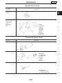
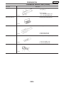
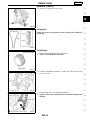
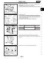
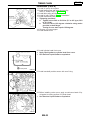
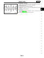
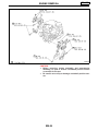
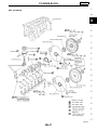
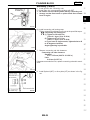
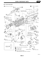
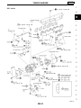
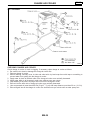
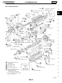
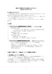
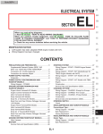
ENGINE MECHANICAL
GI
MA
SECTION
EM
LC
MODIFICATION NOTICE:
EC
I
I
I
FE
I
Engine mounting parts have been modified.
Models with three way catalyst have been introduced for the Middle East.
TB48DE engine has been introduced for Europe. For information and specifications other than those not
described here, refer to Y61 series Service Manual, Supplement-V 1st Revision (Publication No. SM1EY61EG1).
TD42Ti engine has been introduced for Australia. For information and specifications other than those not
described here, refer to Y61 series Service Manual, Supplement-III 3rd Revision (Publication No. SM9EY61CG3).
CONTENTS
TB45E & TB45S
ENGINE REMOVAL.........................................................2
TB48DE
PREPARATION................................................................3
Special Service Tools ..................................................3
Commercial Service Tools ...........................................3
OUTER COMPONENT PARTS .......................................5
POWER VALVE ACTUATOR ..........................................8
COMPRESSION PRESSURE..........................................9
Measurement of Compression Pressure.....................9
OIL PAN .........................................................................10
Removal.....................................................................10
Installation..................................................................12
TIMING CHAIN ..............................................................15
Components...............................................................15
Removal.....................................................................16
Inspection...................................................................19
Installation..................................................................19
OIL SEAL.......................................................................24
CL
MT
AT
Replacement..............................................................24
ENGINE REMOVAL.......................................................26
CYLINDER BLOCK .......................................................27
Assembly ...................................................................28
TD42Ti
PREPARATION..............................................................30
OUTER COMPONENT PARTS .....................................31
TURBOCHARGER.........................................................33
Removal and Installation ...........................................34
Inspection...................................................................34
CHARGE AIR COOLER ................................................38
CYLINDER HEAD..........................................................39
Removal.....................................................................40
Inspection...................................................................40
CYLINDER BLOCK .......................................................41
Inspection...................................................................42
SERVICE DATA AND SPECIFICATIONS (SDS) ..........43
Inspection and Adjustment ........................................43
TF
PD
FA
RA
BR
ST
RS
BT
HA
EL
SE
IDX
EM-1
ENGINE REMOVAL
TB45E & TB45S
SEM959G
SEM060H
EM-2
TB48DE
PREPARATION
Special Service Tools
Tool number
Tool name
Description
KV10111100
Seal cutter
GI
MA
Removing steel oil pan and timing chain case
LC
NT046
KV101056S0
Ring gear stopper
1 KV10105630
Adapter
2 KV10105610
Plate
Preventing crankshaft from rotating
EC
FE
a: 3 (0.12)
b: 6.4 (0.252)
c: 2.8 (0.110)
d: 6.6 (0.260)
e: 107 (4.21)
f: 14 (0.55)
g: 20 (0.79)
h: 14 (0.55) dia.
Unit: mm (in)
NT617
Commercial Service Tools
Tool name
Description
Spark plug wrench
Removing and installing spark plug
CL
MT
AT
TF
PD
FA
RA
NT047
Valve oil seal drift
Installing valve oil seal
a: 25 (0.98) dia.
b: 14.4 (0.567) dia.
c: 11.8 (0.465) dia.
d: 10 (0.39)
e: 11 (0.43)
f: 9 (0.35)
Unit: mm (in)
NT602
Valve guide drift
Removing and installing valve guide
BR
ST
RS
BT
HA
Intake & Exhaust
a = 10 mm (0.39 in) dia.
b = 6.5 mm (0.256 in) dia.
NT015
EL
SE
IDX
EM-3
PREPARATION
Commercial Service Tools (Cont’d)
Tool name
TB48DE
Description
Reaming valve guide q
1 or hole for oversize
valve guide q
2
Valve guide reamer
Intake & Exhaust
d1 = 7.000 mm (0.2756 in) dia.
d2 = 11.19 mm (0.4406 in) dia.
NT016
Valve seat cutter set
Finishing valve seat dimensions
NT048
Front oil seal drift
Installing front oil seal
a = 80 mm (3.15 in) dia.
b = 58 mm (2.28 in) dia.
NT049
Piston pin drift
Removing and installing piston pin
a = 22.5 mm (0.886 in) dia.
b = 12.5 mm (0.492 in) dia.
NT074
Piston ring expander
Removing and installing piston ring
NT030
EM-4
OUTER COMPONENT PARTS
TB48DE
GI
MA
LC
EC
FE
CL
MT
AT
TF
PD
FA
RA
BR
ST
RS
BT
HA
EL
SE
IDX
SEM822GB
EM-5
OUTER COMPONENT PARTS
TB48DE
SEM018H
EM-6
OUTER COMPONENT PARTS
TB48DE
GI
MA
LC
EC
FE
CL
MT
AT
TF
PD
FA
RA
BR
ST
RS
BT
HA
EL
SE
IDX
SEM044H
EM-7
POWER VALVE ACTUATOR
TB48DE
DISASSEMBLY
1. Remove washer and E-ring.
2. Remove actuator assembly.
3. Disconnect shaft lever from actuator rod.
ASSEMBLY
1.
2.
3.
I
Connect shaft lever with actuator rod.
Install actuator assembly with stopper.
Install washer and E-ring.
Use a new E-ring.
ADJUSTMENT
MEM266A
1. Apply vacuum pressure of 33.3 to 40.0 kPa (333 to 400 mbar,
250 to 300 mmHg, 9.84 to 11.81 inHg) to the actuator.
2. Loosen adjusting screw until it is separated from the lever.
3. Screw in adjusting screw until it contacts the shaft lever, and
then screw it in two turns ±45°.
4. Apply vacuum pressure of 40.0±13.3 kPa (400±133 mbar,
300±100 mmHg, 11.81±3.94 inHg) to the actuator. Switch on
and off power valve to check more than three times if the valve
operates smoothly with no play or looseness.
EM-8
COMPRESSION PRESSURE
TB48DE
Measurement of Compression Pressure
1. Warm up engine.
2. Turn ignition switch OFF.
3. Release fuel pressure.
Refer to procedure without CONSULT-II of “Fuel Pressure
Release” in EC section.
Remove fuel pump fuse until the end of step 9.
4. Disconnect ignition coil harness connector.
5. Remove air intake duct, upper collector, throttle body (or electric throttle control actuator), ignition coil and all spark plugs.
6.
7.
8.
I
SEM040H
Attach a compression tester to No. 1 cylinder.
Crank the engine and record the highest gauge indication.
Repeat the measurement on each cylinder as shown below.
Always use a fully-charged battery to obtain specified
engine revolution.
Compression pressure: kPa (bar, kg/cm2, psi)/rpm
Standard
1,226 (12.26, 12.5, 178)/200
Minimum
1,030 (10.30, 10.5, 149)/200
Difference limit between cylinders:
98 (0.98, 1.0, 14)/200
9. If cylinder compression in one or more cylinders is low, pour a
small amount of engine oil into cylinders through the spark plug
holes and retest compression.
I If adding oil helps the compression, piston rings may be
worn or damaged. If so, replace piston rings after checking piston.
I If pressure stays low, a valve may be sticking or seating
improperly. Inspect and repair valve and valve seat. (Refer
to SDS.) If valve or valve seat is damaged excessively,
replace them.
I If compression in any two adjacent cylinders is low and if
adding oil does not help the compression, there is leakage
past the gasket surface. If so, replace cylinder head gasket.
10. Install removed parts in reverse order of removal.
GI
MA
LC
EC
FE
CL
MT
AT
TF
PD
FA
RA
BR
ST
RS
BT
HA
EL
SE
IDX
EM-9
OIL PAN
TB48DE
SEM061H
Removal
1.
2.
3.
I
Remove engine undercover.
Drain engine oil.
Remove steel oil pan bolts.
Loosen steel oil pan bolts in reverse order.
SEM740F
SEM751F
EM-10
OIL PAN
Removal (Cont’d)
TB48DE
4. Remove steel oil pan.
a. Insert seal cutter (SST) between aluminum oil pan and steel oil
pan.
I Be careful not to damage aluminum mating surface.
I Do not insert screwdriver, or oil pan flange will be
deformed.
GI
MA
LC
SEM741F
b. Slide seal cutter by tapping on the side of the tool with a hammer.
EC
FE
CL
MT
SEM742F
5. Remove steel oil pan.
AT
TF
PD
FA
RA
SEM743F
6. Disconnect left side of the tie rod end.
Refer to “STEERING LINKAGE” in ST section.
BR
ST
RS
BT
SEM714F
7. Remove transmission bolts.
HA
EL
SE
IDX
SEM744F
EM-11
OIL PAN
Removal (Cont’d)
TB48DE
8. Remove aluminum oil pan bolts.
I Loosen aluminum oil pan bolts in reverse order.
MEM203A
9. Remove aluminum oil pan using seal cutter (SST).
I Be careful not to damage aluminum mating surface.
I Do not insert screwdriver, or oil pan flange will be
deformed.
10. Remove oil strainer.
SEM746F
Installation
1. Install oil strainer.
2. Install aluminum oil pan.
a. Use a scraper to remove all traces of old liquid gasket from
mating surfaces.
I Also remove traces of old liquid gasket from mating surface of
cylinder block, front cover and steel oil pan.
I Remove old liquid gasket from the bolt hole and thread.
SEM747F
b. Apply a continuous bead of liquid gasket to mating surface of
aluminum oil pan.
I Use Genuine Liquid Gasket or equivalent.
SEM159F
c. Apply liquid gasket to inner sealing surface as shown in figure.
I Be sure liquid gasket is 3.5 to 4.5 mm (0.138 to 0.177 in) in
diameter.
I Attaching should be done within 5 minutes after coating.
SEM745F
EM-12
OIL PAN
Installation (Cont’d)
d.
I
I
I
I
TB48DE
Install aluminum oil pan.
Apply liquid gasket to the shank of the bolts marked with ★.
Use Genuine Liquid Gasket or equivalent.
Tightening should be done within 5 minutes after coating.
Tighten bolts in numerical order.
Tightening torque:
★: 8.43 - 10.8 N⋅m (0.86 - 1.1 kg-m, 75 - 95 in-lb)
Others: 20.6 - 26.5 N⋅m (2.1 - 2.7 kg-m, 16 - 19
ft-lb)
GI
MA
LC
MEM203A
3. Install the transmission bolts. Refer to Service Manual NISSAN
Y61 SUPPLEMENT-V 1st Revision (Publication No. SM1EY61EG1), AT-199.
EC
FE
CL
MT
SEM744F
4. Install steel oil pan.
a. Use a scraper to remove all traces of old liquid gasket from
mating surfaces.
I Also remove traces of old liquid gasket from mating surface of
aluminum oil pan.
AT
TF
PD
FA
RA
SEM749F
b. Apply a continuous bead of liquid gasket to mating surface of
aluminum oil pan.
I Use Genuine Liquid Gasket or equivalent.
I Be sure liquid gasket is 3.5 to 4.5 mm (0.138 to 0.177 in) in
diameter.
I Attaching should be done within 5 minutes after coating.
BR
ST
RS
BT
SEM159F
HA
EL
SE
IDX
EMO0252D
EM-13
OIL PAN
Installation (Cont’d)
c.
I
I
4.
TB48DE
Install steel oil pan.
Tighten in numerical order as shown in the figure.
Wait at least 30 minutes before refilling engine oil.
Connect left side of the tie rod end.
Refer to “STEERING LINKAGE” in ST section.
5. Install in reverse order of removal for remaining steps paying
attention to the following.
I After refilling engine oil, check engine oil level.
I Start engine and check that there is no leakage of engine oil.
SEM751F
EM-14
TIMING CHAIN
TB48DE
GI
Components
MA
LC
EC
FE
CL
MT
AT
TF
PD
FA
RA
BR
ST
RS
BT
HA
1.
2.
3.
4.
5.
Chain tensioner
Camshaft sprocket (Intake)
Camshaft sprocket (Exhaust)
O-ring
Timing chain slack guide
6. Timing chain tension guide
7. Timing chain
8. Crankshaft sprocket
9. Oil pump drive spacer
10. Front cover
EM-15
SEM062H
11. Dowel pin
12. Front oil seal
13. Crankshaft pulley
14. Cylinder head front cover
15. Camshaft position sensor
16. Chain guide
EL
SE
IDX
TIMING CHAIN
Components (Cont’d)
TB48DE
CAUTION
I After removing timing chain, do not turn and camshaft
separately, or valves will strike piston heads.
I When installing chain tensioner, oil seats, or other sliding
parts, lubricate contacting surfaces with new engine oil.
I Apply new engine oil to bolt threads and seat surfaces
when installing camshaft sprocket and crankshaft pulley.
I When removing front cover, remove camshaft position
sensor, then remove timing chain from engine.
I Be careful not to damage sensor edges.
Removal
1. Release fuel pressure.
Refer to “Fuel Pressure Release” in EC section.
2. Remove engine undercover.
3. Drain engine oil.
4. Drain engine coolant from radiator.
Be careful not to spill engine coolant on drive belts.
5. Remove radiator and radiator shroud.
Refer to “Radiator” in LC section.
6. Remove the following belts.
I A/C compressor drive belt
I Power steering oil pump drive belt
I Alternator drive belt
7. Remove fan coupling with fan.
8. Remove power steering oil pump and power steering oil pump
bracket.
9. Remove A/C compressor idler pulley.
10. Remove alternator and alternator bracket.
11. Remove oil pans. Refer to EM-10, “Removal”.
12. Remove air duct from intake manifold collector.
13. Remove vacuum hoses, fuel hoses, and so on.
14. Remove ignition coils.
MEM205A
15. Remove rocker cover bolts in numerical order as shown in the
figure.
MEM206A
EM-16
TIMING CHAIN
Removal (Cont’d)
TB48DE
16. Set No. 1 piston at TDC on its compression stroke.
GI
MA
LC
MEM207A
I
Rotate crankshaft until mating mark on camshaft sprocket
is set at position indicated in figure.
EC
FE
CL
MT
MEM208A
17. Remove camshaft position sensor.
I Do not allow any magnetic materials to contact the camshaft position sensor.
I Be careful not to drop or damage sensor.
18. Remove cylinder head front cover using Seal cutter [SST:
KV10111100].
AT
TF
PD
FA
RA
MEM209AA
19. Remove timing chain guide from camshaft bracket.
20. Attach a suitable stopper pin to chain tensioner to hold plunger
at its compressed position.
21. Remove chain tensioner.
BR
ST
RS
BT
MEM210A
22. Loosen camshaft sprocket bolts holding camshaft at hexagonal
area.
I Apply paint to timing chain and camshaft sprockets for
alignment during installation.
23. Remove camshaft sprockets.
HA
EL
SE
IDX
SEM041H
EM-17
TIMING CHAIN
Removal (Cont’d)
TB48DE
24. Remove front cover bolts at cylinder head front side.
MEM212A
25. Remove starter motor, and set ring gear stopper (SST) using
mounting bolt holes of starter motor.
SEM081H
26. Loosen crankshaft pulley bolt.
27. Remove crankshaft pulley with a suitable puller.
MEM214A
28. Remove water pump pulley and water pump. Refer to “Water
Pump” in LC section (Publication No. SM1E-Y61EG1).
29. Remove front cover bolts as shown.
30. Remove front cover carefully using Seal cutter [SST:
KV10111100].
I Be careful not to damage or bend front end of cylinder
head gasket.
I If cylinder head gasket is damaged, replace it with a new
one.
MEM215A
31.
32.
33.
34.
Remove
Remove
Remove
Remove
timing chain.
oil pump drive spacer.
tension guide and slack guide.
crankshaft sprocket.
SEM019H
EM-18
TIMING CHAIN
Removal (Cont’d)
TB48DE
35. Remove O-rings from front cover.
GI
MA
LC
MEM217A
Inspection
Check for cracks and excessive wear at roller links. Replace if
necessary.
EC
FE
CL
MT
SEM885F
Installation
1. Install crankshaft sprocket on crankshaft.
I There is no installation direction.
AT
TF
PD
FA
RA
MEM267A
2. Position crankshaft so that No. 1 piston is at TDC and key way
is at 12 o’clock.
BR
ST
RS
BT
MEM218A
3. Install timing chain on crankshaft sprocket.
I Support chain with a suitable tool to keep the mating mark
aligned.
HA
EL
SE
IDX
SEM021H
EM-19
TIMING CHAIN
Installation (Cont’d)
TB48DE
4. Install timing chain slack guide and timing chain tension guide.
SEM020H
5. Install camshaft sprocket.
I Set timing chain by aligning mating marks with those of
camshaft sprockets.
MEM221A
6. Install camshaft sprocket bolts and tighten them to specified
torque holding camshaft at hexagonal area.
I Apply new engine oil to bolt threads and seat surface.
SEM042H
7. Install chain tensioner.
I Before installing chain tensioner, insert a suitable pin into
pin hole of chain tensioner to keep plunger compressed.
I After installing chain tensioner, remove the pin to release
plunger.
8. Install timing chain guide to camshaft bracket.
MEM223A
9. Replace front oil seal with new one, and remove all traces of
liquid gasket from mating surface using a scraper.
I Also remove traces of liquid gasket from mating surface of cylinder block.
I For front oil seal replacement, refer to “FRONT OIL SEAL”,
EM-24.
MEM224A
EM-20
TB48DE
TIMING CHAIN
Installation (Cont’d)
10. Apply a continuous bead of liquid gasket to mating surface of
front cover.
I Use Genuine Liquid Gasket or equivalent.
I Attaching should be done within 5 minutes after coating.
GI
MA
LC
MEM225A
11. Install front cover.
I Lift front cover at an angle and install it to mounting position so that front cover will come in contact with both cylinder head gasket lower surface and cylinder block front
surface at the same time.
I Be careful not to damage cylinder head gasket.
EC
FE
CL
MT
PBIC0563E
AT
Bolt No.
a.
b.
Tightening torque N⋅m (kg-m, in-lb)
6.9 - 9.5 (0.70 - 0.97, 61 - 84)
Bolt length
mm (in)
TF
45 (1.77)
16 (0.63)
PD
FA
RA
MEM226A
I
I
Make sure three O-rings are present and new ones.
Be careful not to damage oil seal when installing front
cover.
BR
ST
RS
BT
MEM217A
12. Install front cover bolts at cylinder head front side.
HA
EL
SE
IDX
MEM212A
EM-21
TIMING CHAIN
Installation (Cont’d)
MEM227A
TB48DE
13. Install oil pump drive spacer.
14. Install water pump and water pump pulley.
Refer to “Water Pump” in LC section.
15. Install idler pulley and bracket.
16. Install oil pan. Refer to EM-12, “Installation”.
17. Install crankshaft pulley.
I Tightening procedure
a. Tighten bolt to 54.0 to 63.8 N⋅m (5.5 to 6.5 kg-m, 39.8
to 47.0 ft-lb).
b. Turn bolt 120 to 125 degrees clockwise using marks
provided on bolt flange.
Turning for one mark equals 120 degrees.
18. Remove ring gear stopper.
19. Install starter motor.
20. Install cylinder head front cover.
I Apply liquid gasket to cylinder head front cover.
I Use Genuine Liquid Gasket or equivalent.
MEM228A
21. Install camshaft position sensor with new O-ring.
MEM209AA
22. Before installing rocker cover, apply a continuous bead of liquid gasket to mating surface of cylinder head.
I Use Genuine Liquid Gasket or equivalent.
MEM229A
EM-22
TIMING CHAIN
Installation (Cont’d)
TB48DE
23. Install rocker cover with new rocker cover gasket and tighten
bolts in numerical order as shown in the figure.
24. Install ignition coils.
25. Install alternator and alternator bracket.
26. Install power steering oil pump and power steering oil pump
bracket.
27. Install fan coupling with fan.
28. Drive belts.
For adjusting drive belt deflection, refer to “Checking Drive
Belts” in MA section.
29. Reinstall parts in reverse order of removal.
GI
MA
LC
MMA120A
EC
FE
CL
MT
AT
TF
PD
FA
RA
BR
ST
RS
BT
HA
EL
SE
IDX
EM-23
OIL SEAL
TB48DE
Replacement
VALVE OIL SEAL
1. Remove rocker cover.
2. Remove camshaft.
3. Remove valve spring. Refer to “Removal”, EM-31 (Publication
No. SM1E-Y61EG1).
4. Remove valve oil seal with suitable tool.
Piston concerned should be set at TDC to prevent valve from
falling.
MEM230A
5. Apply new engine oil to new valve oil seal, and install it with
[SST: KV10116300] to dimension as shown.
MEM231A
FRONT OIL SEAL
1.
I
I
I
I
Remove the following parts:
Engine under cover
Radiator and radiator shroud: Refer to “Radiator” in LC section.
Drive belts and cooling fan
Crankshaft pulley and oil pump drive spacer: Refer to “TIMING
CHAIN”, EM-15.
2. Remove front oil seal from front cover.
I Be careful not to scratch front cover.
MEM232A
3. Apply new engine oil to new oil seal and install it using a suitable tool.
I Install new oil seal in the direction as shown in the figure.
SEM715A
MEM233A
EM-24
OIL SEAL
Replacement (Cont’d)
TB48DE
REAR OIL SEAL
1. Separate clutch assembly or automatic transmission. Refer to
“REMOVAL AND INSTALLATION” in MT or AT section.
2. Remove flywheel or drive plate.
3. Remove bolts fixing from both rear and bottom sides.
4. Remove rear oil seal retainer assembly using Seal cutter [SST:
KV10111100].
5. Remove traces of liquid gasket from mating surface of cylinder
block and oil pan using scraper.
I Replace oil seal and retainer assembly as a single unit.
6. Apply a continuous bead of liquid gasket to mating surfaces of
rear oil seal retainer (both for cylinder block and oil pan sides).
I Use Genuine Liquid Gasket or equivalent.
a. Coat of liquid gasket should be maintained within 2.0 to 3.0
mm (0.079 to 0.118 in) and 3.5 to 4.5 mm (0.138 - 0.177 in)
dia. range.
b. Attach oil seal retainer to cylinder block within 5 minutes
after coating.
c. Wait at least 30 minutes before refilling engine oil or starting engine.
SEM064H
GI
MA
LC
EC
FE
CL
MT
AT
TF
PD
FA
RA
BR
ST
RS
BT
HA
EL
SE
IDX
EM-25
ENGINE REMOVAL
TB48DE
SEM063H
CAUTION:
I Before removing engine assembly and transmission
assembly, be sure to remove crankshaft position sensor
on models for Europe.
I Be careful not to drop or damage crankshaft position sensor.
EM-26
CYLINDER BLOCK
TB48DE
GI
MA
LC
EC
FE
CL
MT
AT
TF
PD
FA
RA
BR
ST
RS
BT
HA
EL
SE
IDX
SEM043H
EM-27
CYLINDER BLOCK
TB48DE
Assembly
CRANKSHAFT
1. Set main bearings in their proper positions on cylinder block
and main bearing cap.
I Do not confuse upper and lower sides of main bearings.
SEM986B
2. Install crankshaft and main bearing caps and tighten bolts to
the specified torque.
I Prior to tightening bearing cap bolts, place bearing cap in
its proper position by shifting crankshaft in the axial direction.
I Tighten bearing cap bolts gradually in two or three stages
starting with the center bearing and move outward sequentially.
I After securing bearing cap bolts, make sure crankshaft
turns smoothly by hand.
SEM007C
3. Apply a continuous bead of liquid gasket to mating surfaces of
rear oil seal retainer (both for cylinder block and oil pan sides).
I Use Genuine Liquid Gasket or equivalent.
a. Coat of liquid gasket should be maintained within 2.0 to 3.0
mm (0.079 to 0.118 in) dia. range.
b. Attach oil seal retainer to cylinder block within 5 minutes
after coating.
c. Wait at least 30 minutes before refilling engine oil or starting engine.
MEM268A
4. Measure crankshaft end play.
Crankshaft end play:
Standard
0.05 - 0.169 mm (0.0020 - 0.0067 in)
Limit
0.3 mm (0.012 in)
If end play exceeds the limit, replace No. 6 bearing and measure
again.
If it still exceeds the limit, replace crankshaft also.
SEM006C
5. Install connecting rod bearings in connecting rods and connecting rod caps.
I Confirm that correct bearings are used. Refer to “Inspection”,
EM-47 (Publication No. SM1E-Y61EG1).
I Install bearings so that oil hole in connecting rod aligns with oil
hole of bearing.
SEM159B
EM-28
CYLINDER BLOCK
Assembly (Cont’d)
6.
(1)
I
I
TB48DE
Install pistons with connecting rods.
Install them into corresponding cylinders with SST.
Be careful not to scratch cylinder wall by connecting rod.
Arrange so that front mark on piston head faces toward
front of engine.
GI
MA
LC
SEM008C
(2) Install connecting rod bearing caps.
Tighten connecting rod bearing cap nuts to the specified torque.
: Connecting rod bearing nut
(1) Tighten to 38 to 40 N⋅m
(3.9 to 4.1 kg-m, 28 to 30 ft-lb)
(2) Tighten to 67 to 71 N⋅m
(6.8 to 7.2 kg-m, 49 to 52 ft-lb)
or if you have an angle wrench, tighten bolts to 40
to 45 degrees clockwise.
Angle tightening is preferable.
EM329
7. Measure connecting rod side clearance.
Connecting rod side clearance:
Standard
0.20 - 0.35 mm (0.0079 - 0.0138 in)
Limit
0.40 mm (0.0157 in)
If clearance exceeds the limit, replace connecting rod and/or crankshaft.
EC
FE
CL
MT
AT
TF
PD
FA
RA
SEM162B
8. Install flywheel (M/T) or drive plate (A/T) as shown in the figure.
BR
ST
RS
BT
SEM065H
HA
EL
SE
IDX
EM-29
TD42Ti
PREPARATION
SPECIAL SERVICE TOOLS
* Special tool or commercial equivalent
Tool number
Tool name
Description
KV11105700
Nozzle holder socket
Tightening or loosening injection nozzle holder
ZZA1127D
EM-30
OUTER COMPONENT PARTS
TD42Ti
GI
MA
LC
EC
FE
CL
MT
AT
TF
PD
FA
RA
BR
ST
RS
BT
HA
EL
SE
IDX
SEM071H
EM-31
OUTER COMPONENT PARTS
TD42Ti
SEM072H
EM-32
TURBOCHARGER
TD42Ti
GI
MA
LC
EC
FE
CL
MT
AT
TF
PD
FA
RA
BR
ST
RS
BT
HA
EL
SE
IDX
SEM073H
EM-33
TD42Ti
TURBOCHARGER
Removal and Installation
Turbocharger should not be disassembled.
1. Remove the following.
I Air duct and charge air cooler components
I Heat shield plates
I Exhaust front tube: Refer to FE section.
I Oil tubes
2. Remove turbocharger support.
3. Remove turbocharger from exhaust manifold.
Inspection
Condition 1: Low engine power
Probable cause
Corrective action
Air leak at the connection of compressor housing and suction hose/inlet tube, or inlet and intake manifold.
E
Correct the connection.
Exhaust gas leak at the connection of turbine housing and
exhaust manifold, connecting tube or exhaust outlet.
E
Correct the connection or replace gasket.
Wastegate valve is stuck in open position.
E
Stuck or worn journal or bearing.
E
Broken shaft.
E
Sludge on back of turbine wheel.
E
Broken turbine wheel.
E
Replace turbocharger assembly.
Condition 2: Excessively high engine power
Probable cause
Corrective action
Disconnected or cracked rubber hose of by-pass valve
actuator.
E
Wastegate valve is stuck in closed position.
E
Correct or replace rubber hose.
Replace turbocharger assembly.
Actuator diaphragm is broken.
E
EM-34
TD42Ti
TURBOCHARGER
Inspection (Cont’d)
GI
Condition 3: Excessively high oil consumption, or exhaust shows pale blue smoke
Probable cause
MA
Corrective action
Oil leak at the connection of lubricating oil passage.
E
Oil leak at oil seal of turbine.
E
Oil leak at oil seal of compressor.
E
Worn journal or bearing.
E
Correct the connection.
LC
Replace turbocharger assembly.
EC
FE
CL
MT
AT
Perform the following checks. If NG, replace turbocharger unit.
TF
PD
FA
RA
BR
ST
RS
SEM074H
OIL TUBES
BT
Check tubes for clogging.
HA
EL
SE
SEM075H
IDX
EM-35
TURBOCHARGER
Inspection (Cont’d)
TD42Ti
ROTOR SHAFT
1. Check rotor shaft for smooth rotation.
DEM119
2. Check rotor shaft for carbon deposits.
SEM031F
3. Measure rotor shaft runout.
Runout (Total indicator reading):
Standard
0.12 - 0.17 mm (0.0047 - 0.0067 in)
DEM120
4. Measure rotor shaft end play.
End play:
Standard
0.05 - 0.10 mm (0.0020 - 0.0039 in)
I Do not allow wheels to turn when axial play is being measured.
DEM138
TURBINE WHEEL
Check turbine wheel for the following.
I Oil
I Carbon deposits
I Deformed fins
I Contact with turbine housing
SEM076H
EM-36
TURBOCHARGER
Inspection (Cont’d)
TD42Ti
GI
Check compressor wheel for the following.
I Oil
I Deformed fins
I Contact with compressor housing
MA
18
COMPRESSOR WHEEL
T
LC
H
DEM139
WASTEGATE VALVE
EC
Remove rod pin and check wastegate valve for cracks, deformation
and smooth movement. Check valve seat surface for smoothness.
FE
CL
MT
DEM140
WASTEGATE VALVE ACTUATOR
Mercury manometer
Dial indicator
Wastegate
valve
actuator
Compressed air
Check operation of wastegate valve actuator.
Do not apply more than 96.0 kPa (960 mbar, 720 mmHg, 28.35
inHg) pressure to actuator diaphragm.
Wastegate valve actuator stroke/pressure:
1.5 mm (0.059 in)/85.3 - 90.7 kPa
(853 - 907 mbar, 640 - 680 mmHg,
25.19 - 26.78 inHg)
AT
TF
PD
FA
RA
DEM141
BR
ST
RS
BT
HA
EL
SE
IDX
EM-37
CHARGE AIR COOLER
TD42Ti
SEM077H
CHECKING CHARGE AIR COOLER
Check charge air cooler for mud or clogging. If necessary, clean charge air cooler as follows.
I Be careful not to bend or damage the charge air cooler fins.
1. Remove charge air cooler.
I Before cleaning, securely cover its inlet and outlet with vinyl and wrap them with tape or something to
prevent water from getting into the charge air cooler.
2. Apply water by hose to the back side of the charge air cooler core vertically downward.
3. Apply water again to all charge air cooler core surfaces once per minute.
4. Stop washing if any stains no longer flow out from the charge air cooler.
5. Blow air into the back side of charge air cooler core vertically downward.
I Use compressed air lower than 490 kPa (5 kg/m2, 71 psi) and keep distance more than 30 cm (11.8 in).
6. Blow air again into all the charge air cooler core surfaces once per minute until no water sprays out.
EM-38
CYLINDER HEAD
TD42Ti
GI
MA
LC
EC
FE
CL
MT
AT
TF
PD
FA
RA
BR
ST
RS
BT
HA
EL
SE
IDX
SEM078H
EM-39
TD42Ti
CYLINDER HEAD
Removal
Remove injection nozzle holder and top nozzle gasket.
I Use nozzle holder socket [SST: KV11105700] for No. 1 nozzle
holder.
I Use deep socket wrench for No. 2 to No. 6 nozzle holders.
DEM075
Inspection
COMBUSTION CHAMBER
Identification of combustion chambers
Identification mark
(on combustion chamber)
Outer diameter
“D” mm (in)
1 place
36.985 - 37.011 (1.4561 - 1.4571)
SEM079H
EM-40
Technical Bulletin
CYLINDER BLOCK
TD42Ti
GI
MA
LC
EC
FE
CL
MT
AT
TF
PD
FA
RA
BR
ST
RS
BT
HA
EL
SE
IDX
SEM080H
EM-41
TD42Ti
CYLINDER BLOCK
Inspection
PISTON RING SIDE CLEARANCE
I
Using feeler gauge, measure clearance between piston ring
and piston ring groove.
Unit: mm (in)
SEM024AB
I
I
I
Standard
Limit
Top ring
0.05 - 0.07 (0.0020 - 0.0028)
0.50 (0.0197)
Second ring
0.04 - 0.08 (0.0016 - 0.0031)
0.30 (0.0118)
Oil ring
0.02 - 0.06 (0.0008 - 0.0024)
0.15 (0.0059)
Align top ring and external surface of piston. Measure lower
side clearance of top ring with top ring pressed onto upper side
of ring groove.
If side clearance exceeds the limit, replace piston ring.
Check clearance again. If side clearance still exceeds the limit,
replace piston.
FEM100
PISTON RING END GAP
I
I
Check that cylinder bore diameter is within specifications.
Refer to EM-145, “PISTON TO CYLINDER BORE CLEARANCE” in Service Manual (Publication No. SM7E-1Y61G1).
Using piston, press piston ring to cylinder mid point, and measure end gap.
Unit: mm (in)
Standard
(With cylinder
liner for factory)
Standard
(With cylinder
liner for service)
Top ring
0.25 - 0.45
(0.0098 - 0.0177)
0.35 - 0.60
(0.0138 - 0.0236)
Second ring
0.50 - 0.65
(0.0197 - 0.0256)
0.60 - 0.80
(0.0236 - 0.0315)
Oil ring
0.25 - 0.50
(0.0098 - 0.0197)
0.35 - 0.65
(0.0138 - 0.0256)
FEM101
EM-42
Limit
1.5 (0.059)
SERVICE DATA AND SPECIFICATIONS (SDS)
TD42Ti
GI
Inspection and Adjustment
Valve seat
PISTON RING
Unit: mm (in)
Unit: mm (in)
Standard
Limit
Top
0.05 - 0.07
(0.0020 - 0.0028)
0.50 (0.0197)
2nd
0.04 - 0.08
(0.0016 - 0.0031)
0.30 (0.0118)
Oil
0.02 - 0.06
(0.0008 - 0.0024)
0.15 (0.0059)
MA
Side clearance
LC
EC
Ring gap
FE
With cylinder liner for
factory
SEM146H
Top
0.25 - 0.45
(0.0098 - 0.0177)
2nd
0.50 - 0.65
(0.0197 - 0.0256)
Oil (rail ring)
0.25 - 0.50
(0.0098 - 0.0197)
Intake
Outer diameter “D1”
44.550 - 44.560
(1.7539 - 1.7543)
Inner diameter “D2”
37.9 - 38.1
(1.492 - 1.500)
Diameter of seat “D3”
Cylinder head valve seat diameter
Valve seat face angle “φ”
With cylinder liner for
service
42.5 (1.673)
44.500 - 44.515
(1.7520 - 1.7526)
MT
1.5 (0.059)
Top
0.35 - 0.60
(0.0138 - 0.0236)
2nd
0.60 - 0.80
(0.0236 - 0.0315)
Oil ring
0.35 - 0.65
(0.0138 - 0.0256)
89° - 90°
CL
AT
TF
PD
FA
RA
BR
ST
RS
BT
HA
EL
SE
IDX
EM-43