1
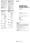
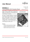
MDX-C800REC
US Model
Canadian Model
SERVICE MANUAL
SUPPLEMENT-1
File this supplement with the service manual.
Subject : Electrical Adjustments
1
ELECTRICAL ADJUSTMENT
TEST MODE
This set has the test mode functionality. The test mode should be
always set before performing adjustments.
<Setting the Test Mode>
1. Input the specified voltage (14.4 V) to the ACC and BATT
terminals.
2. “1:00” is displayed on the LCD display.
3. Press 4 key.
4. Press 5 key.
5. Press 1 key for more than 2 seconds.
6. All segments are lit on the LCD display entering the test mode.
<Releasing the Test Mode>
1. Press OFF key.
DISPLAY TEST
1. Once the test mode is set, each pressing of the DSPL key will
cause the LCD display to change as follows:
All segments ON
Press DSPL key.
Half segments ON (1)
Press DSPL key.
Half segments ON (2)
(The other half segments that were OFF in (1) are ON.)
Press DSPL key.
All segments OFF
Press DSPL key.
TEST MODE STRUCTURE
1. Set the test mode.
2. Insert a disc and press 5 key.
3. Each time 6 key is pressed, the mode will change as follows:
ADJUSTMENT mode “SHUF” indication off
Press 6 key.
PLAY mode “SHUF1” indication is lit.
Press 6 key.
REC mode “SHUF2” indication is lit.
Press 6 key.
Unused mode “SHUF ALL” indication is lit.
Press 6 key.
2
ADJUSTMENT mode: SHUF indication off
Key
Description of test
2
Laser power adjustment mode
3
4
Traverse adjustment mode
Focus bias adjustment mode
5
6
STOP
Switch the mode
ENTER
DSPL
CLV jitter measurement
Select the display
PLAY mode: SHUF1
Key
Description of test
2
Laser power check mode
3
4
Focus + CLV ON
Tracking servo ON/OFF
5
6
STOP
Switch the mode
ENTER
DSPL
REC mode: SHUF2
Key
2
3
4
5
6
ENTER
DSPL
CPLAY mode (middle/outer/inner area)
Select the display
Description of test
Laser power check mode
Focus + CLV ON
Tracking servo ON/OFF
STOP
Switch the mode
CREC mode (middle/outer/inner area)
Select the display
Unused mode: SHUF ALL
NOTES FOR ADJUSTMENT
PREPARING A CONTINUOUSLY RECORDED DISC
1. Perform the following adjustments as listed when the optical pickup and IC400, IC402 and/or IC440 in the MD SERVO board
have been replaced:
(1) Laser power adjustment
(2) Traverse adjustment
(3) Focus bias adjustment
(4) CD error rate check
(5) MO error rate check
2. Set the test mode to perform these adjustments. Release the test
mode after the adjustments are completed.
3. Perform the adjustments in the order that they are listed.
4. Use the following jigs and measuring equipment:
• Test disc (special disc for playback) TDYS-1
(Part No.: 4-963-646-01)
• Laser power meter LPM-8001
(Part No.: J-2501-046-A)
• Oscilloscope (Measure after the probe is calibrated.)
• Digital voltmeter
5. When observing multiple signals with an oscilloscope or other
equipment, take care to prevent connection between VC and
ground in the oscilloscope. (Otherwise, VC and ground are
shorted.)
• This disc is used for focus bias adjustment and error rate check.
This disc is prepared as follows:
1. Set the test mode. (See page 2.)
2. Insert a commercial disc (blank) and press 5 key.
3. Press 6 key twice to set the REC mode.
(Verify that the “SHUF2” indication is lit on the LCD display.)
4. Verify that no number is displayed at the disc No. indicator.
If any number is displayed, repeatedly press DSPL key until the
number disappears (only two digits are displayed).
5. Press ENTER key three times and verify that there is no disc
number displayed (the disc is recorded from the inner area).
If “3” or “7” is displayed, press ENTER key again to clear the
indicator.
LCD display
SHUF 2
Disc No. indicator
REC mode
6. Record the data until the disc number indicator shows “9” and
then press 5 key to stop recording.
7. Press Z key and take out the disc.
The continuously recorded disc for focus bias adjustment and error
rate check is now prepared.
Note:
Take care to prevent vibrations during continuous recording.
3
For the measurement points, see page 7.
<Setting the read power reference value>
8. Press 2 key.
LCD display
LASER POWER ADJUSTMENT
Connection:
laser power
meter
optical pick-up
objective lens
Mode No. 0.7 mW power
(LD Power Adj.)
digital voltmeter
MD servo board
TP (I+3V)
TP (IOP)
+
–
Procedure:
<Setting the write power reference value>
1. Connect a digital voltmeter between TP (I+3V) and TP (IOP).
2. Set the test mode. (See page 2.)
3. Insert a laser power meter into the disc insertion port and press 5
key.
4. Press 2 key.
LCD display
9. Use DISC + or DISC – key to adjust so that the reading on
the laser power meter is 0.69 to 0.71 mW.
10. Press + > M key for 2 seconds to save the data that has
been set in step 9.
11. Press 2 key.
LCD display
Mode No. Main beam conversion power
(LD Power Adj.)
12. Verify that the reading on the laser power meter is 6.0 to 6.4
mW.
If outside the specified value, adjust again from step 1.
13. Press 2 key. The laser power adjustment is completed.
Mode No.
7.0 mW power
(LD Power Adj.)
5. Use DISC + or DISC – key to adjust so that the reading on
the laser power meter is 6.9 to 7.1 mW.
6. Press + > M key for 2 seconds to save the data that has
been set in step 5.
7. Verify that the digital voltmeter reads out the specified value.
Specified value:
Reading on the digital voltmeter: Optical pick-up label indication
value ±10%
(Optical pick-up label)
KMS-263A
27X93
B0825
In this case, Iop = 82.5 mA
Iop (mA) = Reading on the digital voltmeter (mV)/1 (Ω)
4
TRAVERSE ADJUSTMENT
FOCUS BIAS ADJUSTMENT
Connection:
Procedure:
1. Set the test mode. (See page 2.)
2. Insert the continuously recorded disc (see page 3.) and press 5
key.
3. Press 4 key and check the error rate in the current focus bias
setting.
LCD display
oscilloscope
MD servo board
TP (TE)
TP (VC)
+
–
V: 0.5 V/div H: 10 ms/div
Input: DC mode
Procedure:
1. Connect an oscilloscope between TP (TE) and TP (VC).
2. Set the test mode. (See page 2.)
3. Insert the test disc TDYS-1 and press 5 key.
4. Press 3 key.
LCD display
Mode No.
Represents the
Indicates the
(Focus Bias Adj.) initial measurement C1 error rate
<Setting the focus bias point A>
4. Verify that the first digit of the C1 error rate are “0”. Then,
press 4 key.
LCD display
Mode No. Represents Initial set value Value after
(EF-B Adj.) EF adjustment
automatic
adjustment
5. The traverse is automatically adjusted. Verify that the waveform
of the oscilloscope meets the specified value.
6. If outside the specified value, use DISC + or DISC – to adjust
the waveform.
Pressing of DISC + or DISC – will cause the value after
automatic adjustment to be varied.
Mode No.
Represent the
Indicates the C1 error rate
(Focus Bias Adj.) point A measurement
5. Press DISC + key until the C1 error rate value reaches “1.00”
(Note 1).
6. Press + > M key for 2 seconds to save the data set in step
5.
(Traverse waveform)
A
VC
<Setting the focus bias point B>
7. Press 4 key.
LCD display
B
Specification: A = B
7. Press + > M key for 2 seconds to save the data set in steps
5 and 6.
After saving the data, verify that the initial set value is equal to
the value after automatic adjustment.
8. Press 3 key. The traverse adjustment is completed.
Mode No.
Represents the Indicates the C1 error rate
(Focus Bias Adj.) point B measurement
8. Press DISC – key until the C1 error rate value reaches “1.00”
(Note 1).
9. Press + > M key for 2 seconds to save the data set in step
8.
10. Press 4 key.
LCD display
Mode No.
Represents the Indicates the C1 error rate
(Focus Bias Adj.) calculated
point C measurement
5
11. Verify that the calculated point C error rate is “0.30” or less.
If more than “0.30”, adjust again from step 1.
12. Press 4 key. The focus bias adjustment is completed.
Note 1) Since the C1 error rate varies, the average should be read to
perform this adjustment.
Note 2) The relationship between C1 error rate and focus bias amount
is shown in the figure below.
Find out the points A and B in the above adjustment. The
total focus point C is automatically calculated from the
points A and B.
C1 error rate
100
B
MO ERROR RATE CHECK
Procedure:
1. Set the test mode. (See page 2.)
2. Insert the continuously recorded disc (see page 3.) and press 5
key.
3. Press 6 key to set the PLAY mode.
(Verify that the “SHUF1” indication is lit on the display.)
4. Verify that no number is displayed at the disc No. indicator.
If any number is displayed, repeatedly press DSPL key until
the number disappears (only two digits are displayed).
5. Press ENTER key and verify that the disc No. indicator shows
“3”.
If “7” is shown or there is no display, repeatedly press ENTER
key until “3” is displayed.
LCD display
Focus bias amount
A (F. BIAS)
C
SHUF 1
Disc No. indicator
CD ERROR RATE CHECK
Procedure:
1. Set the test mode. (See page 2.)
2. Insert the test disc TDYS-1 and press 5 key.
3. Press 6 key to set the PLAY mode.
(Verify that the “SHUF1” indication is lit on the display.)
4. Verify that no number is displayed at the disc No. indicator.
If any number is displayed, repeatedly press DSPL key until
the number disappears (only two digits are displayed).
5. Press ENTER key and verify that the disc No. indicator shows
“3”.
If “7” is shown or there is no display, repeatedly press ENTER
key until “3” is displayed.
LCD display
SHUF 1
Disc No. indicator
PLAY mode
C1 error rate
6. Verify that the C1 error rate is “0.30” or less.
7. Press 5 key. The CD error rate check is completed.
6
PLAY mode
C1 error rate
6. Verify that the C1 error rate is “0.30” or less.
7. Press 5 key. The MO error rate check is completed.
Measurement points:
— MD SERVO BOARD (SIDE A) —
I+3V
IOP
VC
TE
7
MDX-C800REC
9-870-144-82
Sony Corporation
Audio Entertainment Group
8
2000F0411-1
Printed in Japan ©2000. 6
Published by ME General Engineering Dept.