1
CLS-920i
920i Cargo Lift Scale
®
Installation Manual
96312 Rev A
Contents
1.0
Introduction ................................................................................................................................... 1
1.1 Overview............................................................................................................................... 2
1.2 Considerations Before Installation . . . . . . . . . . . . . . . . . . . . . . . . . . . . . . . . . . . . . . . . . . . . . . . . . 3
1.2.1
CLS Classes and ID Plates . . . . . . . . . . . . . . . . . . . . . . . . . . . . . . . . . . . . . . . . . . . . . . . . . . . . . . . . . . 3
1.3 920i Digital HMI Indicator . . . . . . . . . . . . . . . . . . . . . . . . . . . . . . . . . . . . . . . . . . . . . . . . . . . . . . . . 4
1.3.1
1.3.2
1.3.3
1.3.4
1.3.5
Front Panel . . . . . . . . . . . . . . . . . . . . . . . . . . . . . . . . . . . . . . . . . . . . . . . . . . . . . . . . . . . . . . . . . . . . . .
Enclosures . . . . . . . . . . . . . . . . . . . . . . . . . . . . . . . . . . . . . . . . . . . . . . . . . . . . . . . . . . . . . . . . . . . . . .
Operating Modes . . . . . . . . . . . . . . . . . . . . . . . . . . . . . . . . . . . . . . . . . . . . . . . . . . . . . . . . . . . . . . . . .
Indicator Operations . . . . . . . . . . . . . . . . . . . . . . . . . . . . . . . . . . . . . . . . . . . . . . . . . . . . . . . . . . . . . . .
Softkey Operations . . . . . . . . . . . . . . . . . . . . . . . . . . . . . . . . . . . . . . . . . . . . . . . . . . . . . . . . . . . . . . . .
4
4
5
5
6
1.4 Accepting Weight Data to the Indicator . . . . . . . . . . . . . . . . . . . . . . . . . . . . . . . . . . . . . . . . . . . . . 6
2.0
Scale Base Installation................................................................................................................ 8
2.1
2.2
2.3
2.4
3.0
Unpacking. . . . . . . . . . . . . . . . . . . . . . . . . . . . . . . . . . . . . . . . . . . . . . . . . . . . . . . . . . . . . . . . . . . . . 8
Before Installation . . . . . . . . . . . . . . . . . . . . . . . . . . . . . . . . . . . . . . . . . . . . . . . . . . . . . . . . . . . . . . 9
Tools Needed to Install the CLS-920i Onto the Forklift . . . . . . . . . . . . . . . . . . . . . . . . . . . . . . . . . 9
Scale Base Installation. . . . . . . . . . . . . . . . . . . . . . . . . . . . . . . . . . . . . . . . . . . . . . . . . . . . . . . . . . 10
Indicator Hardware Setup.......................................................................................................... 12
3.1
3.2
3.3
3.4
3.5
Mounting the 920i Indicator. . . . . . . . . . . . . . . . . . . . . . . . . . . . . . . . . . . . . . . . . . . . . . . . . . . . . .
Cable Connections. . . . . . . . . . . . . . . . . . . . . . . . . . . . . . . . . . . . . . . . . . . . . . . . . . . . . . . . . . . . .
Supplying Power to the Indicator From the Forklift Battery . . . . . . . . . . . . . . . . . . . . . . . . . . . .
Routing the Power/Serial Communications Cable . . . . . . . . . . . . . . . . . . . . . . . . . . . . . . . . . . . .
Supplying Power to the Two-Channel iQube Using a Lithium-Ion Battery . . . . . . . . . . . . . . . .
12
13
13
15
16
3.5.1
3.5.2
3.5.3
3.5.4
3.5.5
3.5.6
16
16
17
18
18
19
Lithium-Ion Battery Specifications . . . . . . . . . . . . . . . . . . . . . . . . . . . . . . . . . . . . . . . . . . . . . . . . . . . .
General Precautions . . . . . . . . . . . . . . . . . . . . . . . . . . . . . . . . . . . . . . . . . . . . . . . . . . . . . . . . . . . . . .
Charging the Lithium-Ion Battery . . . . . . . . . . . . . . . . . . . . . . . . . . . . . . . . . . . . . . . . . . . . . . . . . . . . .
Calibrating the Lithium-Ion Battery. . . . . . . . . . . . . . . . . . . . . . . . . . . . . . . . . . . . . . . . . . . . . . . . . . . .
Battery Removal . . . . . . . . . . . . . . . . . . . . . . . . . . . . . . . . . . . . . . . . . . . . . . . . . . . . . . . . . . . . . . . . .
Battery Disposal . . . . . . . . . . . . . . . . . . . . . . . . . . . . . . . . . . . . . . . . . . . . . . . . . . . . . . . . . . . . . . . . .
3.6 Two-Channel iQube Junction Box . . . . . . . . . . . . . . . . . . . . . . . . . . . . . . . . . . . . . . . . . . . . . . . . 20
3.7 Peripheral Scanner. . . . . . . . . . . . . . . . . . . . . . . . . . . . . . . . . . . . . . . . . . . . . . . . . . . . . . . . . . . . . 20
4.0
Configuration of Scale Parameters ........................................................................................... 22
4.1 Configuration Methods . . . . . . . . . . . . . . . . . . . . . . . . . . . . . . . . . . . . . . . . . . . . . . . . . . . . . . . . . 22
4.1.1
4.1.2
4.1.3
4.1.4
iRev Configuration . . . . . . . . . . . . . . . . . . . . . . . . . . . . . . . . . . . . . . . . . . . . . . . . . . . . . . . . . . . . . . . .
Serial Command Configuration . . . . . . . . . . . . . . . . . . . . . . . . . . . . . . . . . . . . . . . . . . . . . . . . . . . . . .
Front Panel Configuration . . . . . . . . . . . . . . . . . . . . . . . . . . . . . . . . . . . . . . . . . . . . . . . . . . . . . . . . . .
Total Scale Configuration . . . . . . . . . . . . . . . . . . . . . . . . . . . . . . . . . . . . . . . . . . . . . . . . . . . . . . . . . .
22
23
23
23
4.2 Menu Structures and Parameter Descriptions . . . . . . . . . . . . . . . . . . . . . . . . . . . . . . . . . . . . . . . 24
4.2.1
SCALES Menu . . . . . . . . . . . . . . . . . . . . . . . . . . . . . . . . . . . . . . . . . . . . . . . . . . . . . . . . . . . . . . . . . . 25
Technical training seminars are available through Rice Lake Weighing Systems.
Course descriptions and dates can be viewed at www.ricelake.com/training
or obtained by calling 715-234-9171 and asking for the training department.
© 11/7/12 Rice Lake Weighing Systems. All rights reserved. Printed in the United States of America.
Specifications subject to change without notice.
Rice Lake Weighing Systems is an ISO 9001 registered company.
Version 1.14, November 7, 2012 2:08 pm
4.2.2
4.2.3
4.2.4
4.2.5
4.2.6
4.2.7
4.2.8
5.0
SERIAL Menu . . . . . . . . . . . . . . . . . . . . . . . . . . . . . . . . . . . . . . . . . . . . . . . . . . . . . . . . . . . . . . . . . . .
FEATURE Menu . . . . . . . . . . . . . . . . . . . . . . . . . . . . . . . . . . . . . . . . . . . . . . . . . . . . . . . . . . . . . . . . .
PFORMT Menu . . . . . . . . . . . . . . . . . . . . . . . . . . . . . . . . . . . . . . . . . . . . . . . . . . . . . . . . . . . . . . . . . .
SETPTS Menu . . . . . . . . . . . . . . . . . . . . . . . . . . . . . . . . . . . . . . . . . . . . . . . . . . . . . . . . . . . . . . . . . .
DIG I/O Menu . . . . . . . . . . . . . . . . . . . . . . . . . . . . . . . . . . . . . . . . . . . . . . . . . . . . . . . . . . . . . . . . . . .
Analog Output Menu. . . . . . . . . . . . . . . . . . . . . . . . . . . . . . . . . . . . . . . . . . . . . . . . . . . . . . . . . . . . . .
Version Menu . . . . . . . . . . . . . . . . . . . . . . . . . . . . . . . . . . . . . . . . . . . . . . . . . . . . . . . . . . . . . . . . . . .
33
37
43
44
45
47
48
Configuration of User Parameters ............................................................................................. 49
5.1
5.2
5.3
5.4
PRO Number . . . . . . . . . . . . . . . . . . . . . . . . . . . . . . . . . . . . . . . . . . . . . . . . . . . . . . . . . . . . . . . . .
More => . . . . . . . . . . . . . . . . . . . . . . . . . . . . . . . . . . . . . . . . . . . . . . . . . . . . . . . . . . . . . . . . . . . . .
Calibration Check . . . . . . . . . . . . . . . . . . . . . . . . . . . . . . . . . . . . . . . . . . . . . . . . . . . . . . . . . . . . .
Utilities Menu . . . . . . . . . . . . . . . . . . . . . . . . . . . . . . . . . . . . . . . . . . . . . . . . . . . . . . . . . . . . . . . . .
5.4.1
5.4.2
5.4.3
50
50
51
52
Diagnostics Softkey . . . . . . . . . . . . . . . . . . . . . . . . . . . . . . . . . . . . . . . . . . . . . . . . . . . . . . . . . . . . . . 52
Cell Emulation . . . . . . . . . . . . . . . . . . . . . . . . . . . . . . . . . . . . . . . . . . . . . . . . . . . . . . . . . . . . . . . . . . . 53
Get Battery Status . . . . . . . . . . . . . . . . . . . . . . . . . . . . . . . . . . . . . . . . . . . . . . . . . . . . . . . . . . . . . . . 53
5.5 Supervisor Menu . . . . . . . . . . . . . . . . . . . . . . . . . . . . . . . . . . . . . . . . . . . . . . . . . . . . . . . . . . . . . . 54
6.0
7.0
8.0
Calibration ................................................................................................................................. 59
Daily Operation .......................................................................................................................... 61
Reports ....................................................................................................................................... 66
8.1 Report Format . . . . . . . . . . . . . . . . . . . . . . . . . . . . . . . . . . . . . . . . . . . . . . . . . . . . . . . . . . . . . . . . 66
8.1.1
8.1.2
8.1.3
9.0
Scanner Option .......................................................................................................................... 70
9.1
9.2
9.3
9.4
9.5
10.0
Open PRO Report . . . . . . . . . . . . . . . . . . . . . . . . . . . . . . . . . . . . . . . . . . . . . . . . . . . . . . . . . . . . . . . 67
Closed PRO Report . . . . . . . . . . . . . . . . . . . . . . . . . . . . . . . . . . . . . . . . . . . . . . . . . . . . . . . . . . . . . . 68
All PRO Report . . . . . . . . . . . . . . . . . . . . . . . . . . . . . . . . . . . . . . . . . . . . . . . . . . . . . . . . . . . . . . . . . . 69
Mounting the Scanner . . . . . . . . . . . . . . . . . . . . . . . . . . . . . . . . . . . . . . . . . . . . . . . . . . . . . . . . . .
Scanning . . . . . . . . . . . . . . . . . . . . . . . . . . . . . . . . . . . . . . . . . . . . . . . . . . . . . . . . . . . . . . . . . . . .
Beeper Indications . . . . . . . . . . . . . . . . . . . . . . . . . . . . . . . . . . . . . . . . . . . . . . . . . . . . . . . . . . . .
Laser Pattern . . . . . . . . . . . . . . . . . . . . . . . . . . . . . . . . . . . . . . . . . . . . . . . . . . . . . . . . . . . . . . . . .
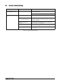
Scanner Troubleshooting . . . . . . . . . . . . . . . . . . . . . . . . . . . . . . . . . . . . . . . . . . . . . . . . . . . . . . .
70
74
75
75
76
Appendix .................................................................................................................................... 77
10.1 Two-Channel IQube Diagnostics . . . . . . . . . . . . . . . . . . . . . . . . . . . . . . . . . . . . . . . . . . . . . . . . 77
10.1.1
Diagnostic Setup . . . . . . . . . . . . . . . . . . . . . . . . . . . . . . . . . . . . . . . . . . . . . . . . . . . . . . . . . . . . . . . . 77
10.2 Indicator Troubleshooting . . . . . . . . . . . . . . . . . . . . . . . . . . . . . . . . . . . . . . . . . . . . . . . . . . . . . . 78
10.2.1
10.2.2
10.2.3
10.2.4
Option Card Diagnostic Errors . . . . . . . . . . . . . . . . . . . . . . . . . . . . . . . . . . . . . . . . . . . . . . . . . . . . . .
Using the HARDWARE Command . . . . . . . . . . . . . . . . . . . . . . . . . . . . . . . . . . . . . . . . . . . . . . . . . . .
User Program Diagnostic Errors . . . . . . . . . . . . . . . . . . . . . . . . . . . . . . . . . . . . . . . . . . . . . . . . . . . . .
Using the XE Serial Command . . . . . . . . . . . . . . . . . . . . . . . . . . . . . . . . . . . . . . . . . . . . . . . . . . . . . .
79
79
79
80
10.3 Regulatory Mode Functions . . . . . . . . . . . . . . . . . . . . . . . . . . . . . . . . . . . . . . . . . . . . . . . . . . . .
10.4 PS/2 Keyboard Interface . . . . . . . . . . . . . . . . . . . . . . . . . . . . . . . . . . . . . . . . . . . . . . . . . . . . . . .
10.5 Data Formats . . . . . . . . . . . . . . . . . . . . . . . . . . . . . . . . . . . . . . . . . . . . . . . . . . . . . . . . . . . . . . . .
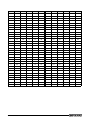
10.6 ASCII Character Chart . . . . . . . . . . . . . . . . . . . . . . . . . . . . . . . . . . . . . . . . . . . . . . . . . . . . . . . . .
10.7 Digital Filtering . . . . . . . . . . . . . . . . . . . . . . . . . . . . . . . . . . . . . . . . . . . . . . . . . . . . . . . . . . . . . . .
10.8 Conversion Factors for Secondary Units . . . . . . . . . . . . . . . . . . . . . . . . . . . . . . . . . . . . . . . . . .
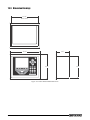
10.9 Dimension Drawings . . . . . . . . . . . . . . . . . . . . . . . . . . . . . . . . . . . . . . . . . . . . . . . . . . . . . . . . . .
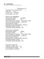
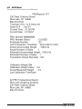
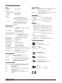
10.10 920i Specifications. . . . . . . . . . . . . . . . . . . . . . . . . . . . . . . . . . . . . . . . . . . . . . . . . . . . . . . . . . .
81
82
83
84
86
87
89
90
Rice Lake continually offers web-based video training on a growing selection
of product-related topics at no cost. Visit www.ricelake.com/webinars.
ii
920i Installation Manual
1.0 Introduction
This manual is intended for use by individuals responsible for installing the CLS-920i Cargo Lift Scale along with
the 920i HMI digital weight indicator. This manual covers information on the installation of the scale carriage,
signal cable installation (if applicable), and the installation, configuration, and calibration of the 920i HMI digital
weight indicator.
While the functionality remains the same for the standard 920i HMI digital weight indicator, there are certain
Note menu choices found in the User Configuration section of this manual that are specific to this application.
The CLS-920i Operator Card, PN 96313 included with this manual, provides basic operating instructions for users
of the CLS-920i and the 920i HMI digital weight indicator. Please leave the operator card with the indicator when
installation and configuration is complete.
Manuals can be viewed or downloaded from the Rice Lake Weighing Systems website at
www.ricelake.com/manuals
Warranty information can be found on the website at www.ricelake.com/warranties
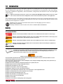
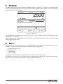
Safety
Safety Symbol Definitions:
DANGER Indicates an imminently hazardous situation that, if not avoided, will result in death or serious injury.
Indicates a potentially hazardous situation that, if not avoided could result in death or serious injury, and
WARNING includes hazards that are exposed when guards are removed.
CAUTION Indicates a potentially hazardous situation that, if not avoided may result in minor or moderate injury.
Indicates information about procedures that, if not observed, could result in damage to equipment or
Important corruption to and loss of data.
General Safety
Do not operate or work on this equipment unless you have read and understand the instructions and
warnings in the Installation, Operation and Service Manuals. Failure to follow the instructions or heed
the warnings could result in injury or death. Contact any Rice Lake Weighing System dealer for
replacement manuals. Proper care is your responsibility.
WARNING
Failure to heed may result in serious injury of death.
Some procedures described in this manual require work inside the indicator enclosure. These procedures are to be
performed by qualified service personnel only.
Take all necessary safety precautions when installing the scale carriage including wearing safety shoes, protective eye
wear, and using the proper tools.
DO NOT allow minors (children) or inexperienced persons to operate this unit.
DO NOT operate without all shields and guards in place.
DO NOT jump up and down on the scale.
DO NOT use for purposes other then weight taking.
DO NOT place fingers into slots or possible pinch points.
DO NOT use any load bearing component that is worn beyond 5% of the original dimension.
DO NOT use this product if any of the components are cracked.
DO NOT exceed the rated load limit of the unit.
DO NOT make alterations or modifications to the unit.
DO NOT remove or obscure warning labels.
DO NOT use near water.
Keep hands, feet and loose clothing away from moving parts.
Introduction
1
1.1
Overview
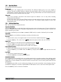
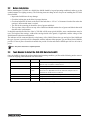
The CLS-920i Cargo Lift Scale is a rugged, dependable cargo lift scale that can withstand many years of repeated
use. When mounted on a forklift, the CLS-920i saves time and money. It immediately weighs the load when it is
picked up with a forklift instead of carrying the load to a floor scale.
The CLS-920i is used with Rice Lake’s 920i HMI digital weight indicator and the setup and calibration of the
indicator is discussed in detail in this manual.
Onboard Features
Features of the basic cargo lift scale include:
Features of the scale carriage include:
• NTEP approved, Class III, 5,000 lb, 1:1000
• Class II forklift with 16" cleat style carriage
• Two (2) stainless steel load cells
• Cover plate
• Mechanical overload protection
• Flexure plates with bolts welded into place
• Welded centering pin
• View port
• Two-channel iQube
• Wired or wireless communication
Figure 1-1. Fork Lift with CLS-920i
2
CLS-920i Installation Manual
1.2
Considerations Before Installation
While the CLS-920i Cargo Lift Scale will fit most typical forklifts, there are certain considerations that must be
taken into account prior to installing the scale. Due to the extra weight of the CLS-920i, the net lifting capacity of
the forklift is decreased by approximately 10%. Use the following formula below, to calculate the net capacity of
the unit.
NOTE: Formulas can give you a good estimate of how capacity will be affected. But you should work closely with your
forklift manufacturer before making a decision. Their data reflects, in most cases, testing with specific forklifts and
attachments.
Net Capacity = A(B + C) - D (E + F)
E+G+H
Where:
A = Truck basic capacity in pounds
B = Inches from the front wheel center line to fork face
C = Inches from fork face to truck rating point (usually 24")
D = Weight of the scale in pounds (428 lbs)
E = Inches from the front wheel center line to the carriage face
F = Inches from the carriage face to scale Horizontal Center of Gravity (HCG)
G = J + K (inches from the carriage face to rear face of load
H = Inches from fork face to new truck rating point
J = Thickness of fork
K = Thickness of scale
Another consideration is the indicator power source will be connected directly to the battery of the
CAUTION forklift. Most typical is 12 volts for propane, gas and diesel forklifts. However, some diesel forklifts are 24
volts.
The CLS Series Cargo Lift scale will not operate on a positive ground forklift. Verify the forklift has a
negative ground electrical system. Refer to the forklift users manual to further verify grounding
requirements.
1.2.1
CLS Classes and ID Plates
During the initial sale or installation of the CLS-920i, you need to remind your customer that they must have an ID
plate on their forklift updated stating the new lifting capacity and center of gravity information. This requirement is
per OSHA rules and regulations.
CLS-920i Installation Manual
3
1.3
920i Digital HMI Indicator
Features of the basic 920i include:
• Support for A/D scale or serial scale inputs. The maximum number of scale inputs is 28; these can be
combined to represent up to 32 scale configurations.
• Four digital I/O channels on main board, each configurable as either input or output.
• Four serial ports on main board (Ports 1–4) support duplex RS-232 up to 115200 bps. Port 2 supports
hardware handshaking and remote keyboard input; Ports 3 and 4 support 20mA output; Port 4 supports
2-wire RS-485 communications.
• External DB-9 and DIN-8 connectors for serial connection to a PC and attachment of PS/2-type remote
keyboard.
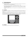
1.3.1
Front Panel
The 920i front panel, shown in Figure 1-2, consists of a 27-button keypad with a large backlit LCD display. The
keys are grouped as five configurable softkeys, five primary scale function keys, four navigation keys, and numeric
entry keys.
Weight information is displayed with a graphical scale in six font sizes up to 1.2 inches. Up to four scale widgets
can be displayed in legal-for-trade, multiple-scale applications. Status areas on the display are used for operator
prompts and entering data. The remainder of the display can be graphically configured for representation of a
specific application. Display contrast can be adjusted with the LCD contrast potentiometer.
40'5,&: 40'5,&: 40'5,&: 40'5,&: 40'5,&:
6/*54
13*/5
Figure 1-2. 920i Front Panel
1.3.2
Enclosures
The 920i is housed in a stainless steel enclosure that is rated for NEMA 4X/IP66.
4
CLS-920i Installation Manual
1.3.3
Operating Modes
The 920i has two modes of operation:
Normal mode
Normal mode is the weighing mode of the indicator. The indicator displays gross, net, or tare weights as
required, using the secondary display to indicate scale status and the type of weight value displayed. Once
configuration is complete and a legal seal is affixed to the large fillister-head screw on the indicator enclosure,
this is the only mode in which the 920i can operate.
Setup mode
Most of the procedures described in this manual require the indicator to be in setup mode, including
configuration and calibration.
To enter setup mode, remove the large fillister head screw from the enclosure. Insert a screwdriver or a similar
tool into the access hole and press the setup switch once. The indicator display changes to show scale
configuration menus.
1.3.4
Indicator Operations
Basic 920i operations are summarized below:
Toggle Gross/Net Mode
Press the GROSS/NET key to switch the display mode from gross to net, or from net to gross. If a tare value has been
entered or acquired, the net value is the gross weight minus the tare. If no tare has been entered or acquired, the
display remains in gross mode.
Gross mode is indicated by the word Gross (or Brutto in OIML mode); net mode is indicated by the word Net.
Toggle Units
Press the UNITS key to switch between primary, secondary, and tertiary units.
Zero Scale
1. In gross mode, remove all weight from the scale and wait for the standstill annunciator (
).
2. Press the ZERO key. The center of zero (
) annunciator lights to indicate the scale is zeroed.
Acquire Tare
1. Place container on scale and wait for the standstill annunciator (
2. Press the TARE key to acquire the tare weight of the container.
3. Display shifts to net weight and shows the word Net on the display.
).
Remove Stored Tare Value
1. Remove all weight from the scale and wait for the standstill annunciator (
).
2. Press the TARE key (or, in OIML mode, the ZERO key). Display shifts to gross weight and shows the word
Gross.
Print Ticket
1. Wait for the standstill annunciator (
).
2. Press the PRINT key to send data to the serial port.
Accumulator Functions
The accumulator must be enabled before use in either normal mode or setpoint operations. Once enabled, weight
(net weight if a tare is in the system) is accumulated whenever a print operation is performed using the PRINT key,
digital input, or serial command. The scale must return to zero (net zero if a tare is in the system) before the next
accumulation.
The Display Accum softkey can be configured to display the current accumulator value. Printing while the
accumulator is displayed, or when the setpoint PSHACCUM function is active, uses the ACCFMT print format
Press the CLEAR key twice to clear the accumulator.
CLS-920i Installation Manual
5
1.3.5
Softkey Operations
Softkeys can be defined to provide additional operator functions for specific applications. Softkey assignments are
listed on the tabs shown at the bottom of the LCD display; softkey functions are activated by pressing the arrow keys
below the softkey tabs (Figure 1-2 on page 4).
The particular set of softkeys shown on the display is determined by the indicator configuration and program.
Softkey
Description
Time/Date
Displays current time and date; allows time and date change.
Display Tare
Displays tare value for the current scale
Display Accum
Displays accumulator value, if enabled, for the current scale.
Display ROC
Displays rate-of-change value, if enabled, for the current scale.
Setpoint
Displays a menu of configured setpoints; allows display and change of some
setpoint parameters.
Batch Start
Starts a configured batch.
Batch Stop
Stops a running batch and turns off all associated digital outputs. Requires a batch
start to resume processing.
Batch Pause
Pauses a running batch. (Same as stop, but digital outputs, if on, are not turned
off.)
Batch Reset
Stops a batch and resets it to the first batch step.
Weigh In
Allows truck ID entry; generates weigh-in ticket for truck weighing applications.
Weigh Out
Allows truck ID entry; generates weigh-out ticket for truck weighing applications.
Truck Regs
Displays truck register; allows deletion of individual or all entries. Truck register can
be printed by pressing the PRINT key while the truck register is displayed.
Unit ID
Allows display or change of Unit ID.
Select Scale
For multi-scale applications, provides a prompt to enter the scale number to be
displayed.
Diagnostics
Provides access to diagnostic displays for the attached two channel iQUBE.
F1–F10
User-programmable keys; defined by application.
More…
For applications with more than five defined softkeys, the More… key is
automatically assigned to the fifth softkey position. Press More… to toggle
between groups of softkeys.
Table 1-1. Configurable Softkeys
1.4
Accepting Weight Data to the Indicator
The 920i can accept data in two different ways from the two-channel iQube and depending upon which version of
the CLS-920i is purchased, will come with different components. They are:
• Wired - Coil Cable
Figure 1-3. Coil Wired Signal Cable That Runs Between the 920i Indicator and the Two-Channel iQube
•
6
Wireless - Attached onto the back of the 920i HMI digital weight indicator and collects data from the
two-channel iQube without the use of a coil wire cable but instead uses a lithium-ion battery which is
housed on the scale itself for power.
CLS-920i Installation Manual
W ireless
communication
between the 920i
indicator and the
two-channel iQube
which is located on the
forklift and is powered
by a lithium-ion battery
housed in a battery box.
Figure 1-4. Wireless Version of Communication
CLS-920i Installation Manual
7
2.0 Scale Base Installation
This section describes procedures for installing the CLS-920i scale base.
Take all necessary safety precautions when installing the scale carriage. including wearing safety shoes,
WARNING protective eyewear and using the proper tools which are listed in Section 2-3.
The CLS-920i Cargo Lift Scale is shipped from the factory with the scale already calibrated to the indicator.
Minimal recalibration and adjustments might be necessary once the scale is installed onto the forklift. Those
calibration steps are contained in Section 6.0.
2.1
Unpacking
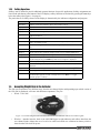
The CLS-920i Cargo Lift Scale is shipped upright on a sealed pallet as shown in Figure 2-1.
Component
parts inside of
box
Figure 2-1. CLS-920i Packaging
Upon receipt of the shipping pallet, inspect it for any visible signs of damage. Immediately after unpacking,
visually inspect the contents to ensure all components are included and undamaged. The shipping pallet should
contain the following:
• One (1) scale carriage assembly with cover plate
• Indicator component box which includes the following:
- One (1) electronic indicator with mounting bracket and hardware
- One (1) power cable
- CLS-920i Cargo Lift Installation manual
• Hardware component box which includes the following:
- Two (2) cleats with four bolts
- Cage clamp mounting assembly and hardware
- Two (2) lithium-ion batteries (wireless version)
- Two-bay battery charger (wireless version)
- Coiled interface cable (wired version)
To ensure that all products received from the manufacturer are in good shape upon arrival, it is recommended
Note to fully inspect all contents and properly fill out the bill of lading.
If any parts were damaged in shipment, notify Rice Lake Weighing Systems and the shipper immediately.
8
CLS-920i Installation Manual
2.2
Before Installation
Before installing the CLS-920i on a forklift, the forklift should be in good operating condition in order to get the
optimal amount of weighing accuracy. The following items are things to look for prior to installing the CLS-920i
onto a forklift:
• Inspect the forklift tines for any damage.
• Check the locking pin on the forks for proper function.
• Check and adjust the lift chain so the heel of the forks have a 1/2" to 1" of clearance from the floor when the
carriage is down and the mast is vertical.
• The slot for the centering pin should be clear of grease and debris.
• The top cleats of the scale rest on top of the forklift and should remain clear of grease and debris that could
alter the scales’ performance.
It should be noted that while Rice Lake’s CLS-920i will fit most typical forklifts, some considerations must be
note. The height of the carriage, width of the carriage inside of the guards, if applicable, and the voltage of the
forklift must be taken into consideration.
The indicator will be connected directly to the battery of the forklift. Ensure the type and style of the forklift and
the type of power it provides will be compatible with the indicator. Most propane, gas, and diesel fueled forklifts
provide 12 volts of power. Some diesel models also provide 24 volts and electric forklifts provide 36 to 48 volts of
power.
Note All systems must have a negative ground.
2.3
Tools Needed to Install the CLS-920i Onto the Forklift
Once the forklift is deemed in good mechanical and operating condition, you’ll need the following tools to remove
it from its shipping pallet and install onto the forklift.
Tool
Size
Purpose of Tool
Socket Wrench
3/4"
To unbolt the fastening bolts holding the scale to the pallet and to
open the top cover plate for wired versions
Allen Wrench
1/2"
To bolt and unbolt the bottom cleats of the scale
Wrench - 2" adjustable
1- 1/2"*
1-5/8"*
For adjusting the shim bolts and jam nuts
*Note: Use a 2" adjustable as both the shim bolts and jam nuts are
painted and a smaller wrench wouldn’t fit.
Tin Snips or Band Cutters
To cut the metal banding surrounding the CLS while on the pallet
Torque Wrench w/ 1/2" Allen
To tighten the cleats to 125 ft-lbs
Electric Grinder - if necessary
For grinding the center pin if necessary
Table 2-1. Recommended Tools for Unpacking the CLS-920i
CLS-920i Installation Manual
9
2.4
Scale Base Installation
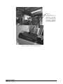
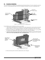
The scale and indicator are shipped in an upright position as illustrated in Figure 2-2 and is enclosed in a protective
wood cover. The upright position allows for ease of installation, especially if one person is installing the scale.
Protective
wood covering
Protective wood
enclosure for
indicator
Step 1: Clip
metal bands
with band cutter
Steel shipping
pallet
Figure 2-2. Scale Component Parts on Shipping Pallet
Use the following steps to install the scale base to the forklift.
1. Clip the three metal bands that are encircling the scale and component box on the backside of the pallet
(shown in Figure 2-2) and also remove the protective wood pieces which protect the sides of the scale.
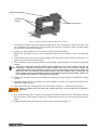
2. Remove the wooden cover containing the indicator. It should be noted that there are two screws holding
the indicator to the shipping pallet. Back those two screws out to remove the indicator.
3. Loosen the bolts from the scale carriage assembly and back them out using a 3/4" socket wrench. The nuts
holding the bolts on the backside of the scale are welded onto the scale which requires the use of only one
socket wrench. This is what holds the scale in an upright position.
Step 2: Remove
wooden cover
containing
indicator
Step 3: Back out
anchoring bolts using
3/4" socket wrench and
discard bolts
Step 4: Remove
front portion of
steel pallet.
Figure 2-3. Bolt Location on Pallet
4. Remove the front portion of the steel pallet that the scale is sitting on.
10
CLS-920i Installation Manual
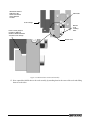
Anti-shift centering pin
Shim bolt hole
location
Top cleat location
Figure 2-4. Removal of Steel Pallet and Top Cleat Locations
5. Verify that the shim bolts are flush with the back plate of the scale. Not doing so will place the entire scale
out of alignment when attaching it onto the forklift and will make it difficult to make final adjustments
once the scale is mounted to the forklift.
6. Seal the two-channel iQube if it is to be used in Legal-For-Trade applications.
7. Making sure the forklift tines are removed from the forklift, move the forklift in close to the pallet and
scale.
8. Carefully and slowly raise the scale carriage slightly so the top cleats (cleat location shown in Figure 2-4)
of the scale hook onto the forklift carriage.
9. Ensure that the anti-shift centering pin on the scale assembly is aligned with the center notch on the forklift
carriage.
The scale’s centering pin should be aligned with the middle notch of the truck carriage. Verify that the
Note centering pin is adjusted so that the pin is located well within the center notch area of the carriage. The
centering pin should not touch the bottom of the notch on the original carriage, as this will cause side to side
tilting of the scale. The outside top cleats provide support to the scale assembly and the centering pin only
helps to position the scale on the forklift carriage. The centering pin should not bear any weight. If it does, the
use of a grinder to grind down the centering pin will remedy that.
10. Tilt the mast forward to catch the scale assembly and carefully raise the carriage to a comfortable working
position.
11. Attach the bottom cleats to the bottom of the scale assembly (see Figure 2-5), so that the lip of the cleat is
behind the original carriage.
12. Torque the bottom cleat retaining bolts to 125 ft-lbs (shown in Figure 2-5 for bottom cleat location).
Failure to properly torque the safety plate retaining bolts may result in bodily harm or damage to
WARNING equipment.
13. Next, adjust the shim bolts so that they are adjusted for minimal clearance between the bottom cleats and
the scale carriage. This clearance needs to be .020 inch thickness and can be measured by using a feeler
gauge.
14. Tighten the shim bolt jam nuts and verify their clearances as shown in Figure 2-5.
CLS-920i Installation Manual
11
Illustration shown is
with part of the
flexure removed to
show shim bolt
location.
Shim bolts
Scale carriage
Bottom
cleat
retaining
bolts
Insert a feeler gauge to
measure a .020 inch
thickness between bottom
cleat and scale carriage.
Bottom cleat
Figure 2-5. Bottom Cleat Location and Assembly
15. Now reattach the forklift tines to the scale assembly by attaching them in the center of the scale and sliding
them off to the sides.
12
CLS-920i Installation Manual
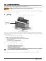
3.0 Indicator Hardware Setup
3.1
Mounting the 920i Indicator
Location of the indicator is a matter of operator preference and should be installed in a location that allows for free
vision.
The universal mounting bracket which is included (shown in Figure 3-1 with the optional bar code scanner),
enables the indicator to be mounted to the safety cage using the supplied hardware.
Figure 3-1. CLS Mounting Bracket
The indicator tilt position is adjustable by using a wrench so you can pick the best viewing angle for the operator.
Vibration isolators are also included in the supplied mounting bracket hardware. This cushions the indicator from
vibration. These vibration isolators are shown below in Figure 3-2.
Vibration
Isolators
Figure 3-2. Vibration Isolator Control Location
CLS-920i Installation Manual
12
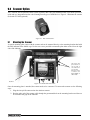
3.2
Cable Connections
The 920i indicator provides four cord grips and two MIL-C connectors for cabling into the indicator. The free cord
grips come with a plug installed to prevent moisture from entering the enclosure.
Figure 3-3 shows the assignments for the 920i cord grips.
Wireless LAN
- optional
MIL-C
power
To scanner optional
On/Off
power
toggle
To wireless
transceiver
Wired
version plug
Figure 3-3. 920i Cord Grip Assignments
3.3
Supplying Power to the Indicator From the Forklift Battery
The indicator power source will be connected directly from the battery of the forklift. Most
CAUTION typical is 12 volts for propane, gas, and diesel forklifts. However, some diesel forklifts are 24
volts.
The CLS series cargo lift scale will not operate on a positive ground forklift. Verify the forklift has a
negative ground electrical system.
Refer to the forklift users manual to further verify grounding requirements.
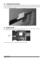
There is a supplied on/off power toggle switch which manually cuts power from the battery of the forklift. This
way there won’t be any additional draw on the battery when the scale is not in use.
On/off toggle switch
location on 920i
Figure 3-4. Toggle Switch Location
13
CLS-920i Installation Manual
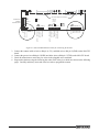
The indicator draws its power from the forklift battery. After the indicator is mounted, run the power cable along
the forklift chassis down to the forklift battery.
Run power cable along
chassis to the forklift
scale battery
Figure 3-5. Run Power Cable to the Forklift Battery
Note DO NOT plug in the power connector into the bottom of the indicator until power hookup is completed.
A supplied in-line fuse is also included with the CLS-series cargo lift scale. The fuse comes enclosed in an in-line
fuse holder (shown in Figure 3-6) and is attached where the stripped termination of the wires is located.
Replacement of the in-line fuse is described in the CLS-series Service manual if needed.
Figure 3-6. Inline Fuse
Attach the three stripped wires to the forklift battery using the following wire code.
Note Supplied termination hardware includes (3) 1/4" eyelits for 1/4" bolts..
Wire Color
Signal
Red
Positive on Battery
Black
Negative on Battery
Blue
Ground/Chassis
Table 3-1. Power Hookups to Forklift Battery
CLS-920i Installation Manual
14
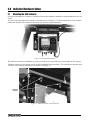
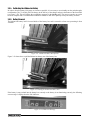
3.4
Routing the Power/Serial Communications Cable
Special care should be taken when routing the power/serial communications cable (if the standard coiled wired
version is used). To ensure that the signal cable is installed properly and away from situations that could cause it
harm use the following steps.
1. Mount the indicator to the forklift per instructions in Section 3.1.
2. Lay the coiled up signal cable along the route between the indicator and the forklift scale.
Figure 3-7. Signal Cable Between Scale and Indicator
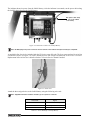
The preferred route is through the center of the mast. If it has a three stage mast, route along side the mast
as shown in Figure 3-8.
Figure 3-8. Signal Cable Located Between the Scale and the Indicator
3. Secure with cable ties at the bottom of the scale and at the top of the mast
4. Slowly and carefully extend the mast to all positions to confirm that the cable isn’t pulled too tight or that
there are pinch points along the way.
5. Check for proper signal cable clearance as the side shifter is moved back and forth.
15
CLS-920i Installation Manual
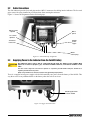
3.5
Supplying Power to the Two-Channel iQube Using a Lithium-Ion Battery
If using a wireless version of the CLS-920i, the CLS scale uses a supplied lithium-ion battery to supply power to
the two-channel iQube. The wireless version of the CLS-920i does not come with a coiled cable. The lithium-ion
battery is located on the top of the cover plate in a painted enclosure.
Figure 3-9. Lithium-Ion Battery Location
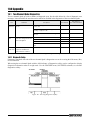
3.5.1 Lithium-Ion Battery Specifications
Nominal Capacity
6600 mAh
Nominal Voltage
11.1 V
Charging Method
Constant Current
Constant Voltage
Charging Voltage
12.6 V
Charging Current
4.0 A
Charging Time
100% @ 8 hours
Ambient Temperature
Charge
0° - +40°C
Discharge
-20° - +60°C
Storage
-20° - +50°C
Weight (Maximum)
Dimensions (Maximum)
430 g
Depth
22.80 mm
Length
214.0 mm
Volumetric Energy Density
466 Wh/I
Gravimetric Energy Density
167 Wh/kg
Maximum Hours of Charge
24 Hours
Nominal Capacity
6600 mAh
Table 3-2. Battery Specifications
3.5.2 General Precautions
There are some precautions that should be taken when handling lithium-ion batteries.
Handling
•
•
•
•
•
•
Do not short circuit
Do not immerse in water
Do not disassemble or deform battery
Keep away from excessive heat (+100°C) or dispose of battery in fire
Avoid excessive physical shock or vibration
Keep out of reach of children
CLS-920i Installation Manual
16
• Never use a battery that appears to have suffered abuse
• Do not crush or attempt to disassemble the battery
Charge and Discharge
• Battery must be charged in an appropriate charger only
• Never use a modified or damaged charger
• Specified product use only
Storage
• Store in a cool, dry and well ventilated area
Disposal
• Regulations vary for different countries. Dispose of in accordance with local regulations
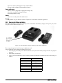
3.5.3 Charging the Lithium-Ion Battery
The lithium-ion battery comes with a two-bay, level-3 stand alone smart battery charger, a DC power jack, and a
AC power cord as shown in Figure 3-10.
To c a l i b r a t e
the battery
pack, press
the button on
front label.
Figure 3-10. Two-Bay Battery Charger and Parts for the Lithium-Ion Battery
The average charge time for the battery is eight hours each.
Use the following steps to charge the battery prior to use:
1. Insert the plug end of the power cable into the DC power jack on the battery charger and the AC plug into
an outlet.
2. Insert battery into the bay.
3. There is one LED indicator in front of each bay which will illuminate to indicate the status of the battery as
follows:
Signal
Description
Off
No Battery
Green Flashing
Fast Charging
Green Solid
Fully Charged
Yellow Flashing
Recalibrating
Yellow/Green Alternating
Recalibrating
Yellow Solid
Standby
Red Flashing
Error
Table 3-3. Battery Charging LED Signals
17
CLS-920i Installation Manual
3.5.4 Calibrating the Lithium-Ion Battery
In order to keep the battery fuel gauge as accurate as possible, it is necessary to occasionally run the pack through a
recalibration cycle. To do this, place the battery in the left bay of the charger and press the button on the front label
(see Figure 3-10). This will initiate the recalibration sequence in the left bay only. The process can take up to nine
hours to complete and a recommended recalibration should be done once quarterly to keep the battery accurate.
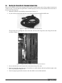
3.5.5 Battery Removal
The lithium-ion battery itself is housed inside of the battery box and is encased in a foam core protecting it from
vibration.
Figure 3-11. Lithium-ion Battery Box Opened
Figure 3-12 shows how to pull the lithium-ion battery out of the battery box.
Figure 3-12. Pulling the Lithium-Ion Battery Out
If the battery is not put back into the battery box correctly or the battery is not functioning correctly, the following
error message is displayed on the 920i indicator.
Figure 3-13. Comm Error Message
CLS-920i Installation Manual
18
3.5.6 Battery Disposal
When using Lithium-Ion batteries, be sure to observe the following precautions for disposal as stated in the
material safety data sheet regarding lithium-ion batteries.
19
CLS-920i Installation Manual
3.6
Two-Channel iQube Junction Box
The two-channel iQube sits in an area between the front and back plate of the scale itself, providing protection for
the two-channel iQube. The two-channel iQube comes from the factory pre-wired and no additional work needs to
be done to it. Should the user need to replace load cells, then additional information on wiring is located in the
CLS-Series Service Manual, PN 96314.
Figure 3-14. Location of Two-Channel iQube on CLS-Series Scale
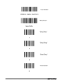
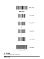
3.7
Peripheral Scanner
The CLS-920i has the ability of scan bar codes of various products being moved. The scanner is mounted in a
convenient location next to the indicator as shown in Figure 3-15.
Peripheral
Scanner
Figure 3-15. Scanner Location
Additional information on the scanner is found in Section 9 of this manual.
CLS-920i Installation Manual
20
4.0 Configuration of Scale Parameters
While the fuctionality remains the same for a standard 920i HMI indicator, there are certain menu choices that
Note need to be changed in the User Configuration section of this manual specific to the proper functioning of the
CLS-Series Cargo Lift Scale.
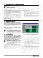
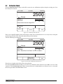
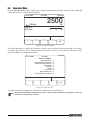
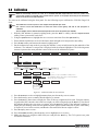
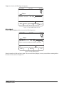
To configure the 920i indicator, the indicator must be
placed in setup mode. The setup switch is accessed by
removing the large fillister head screw on the backplate
of the universal and deep enclosures. Switch position is
changed by inserting a screwdriver into the access hole
and pressing the switch.
When the indicator is placed in setup mode, a series of
menus is shown across the top of the display, along
with the words Scale Configuration. The SCALES menu
is highlighted as the first used to configure the
indicator. Detailed descriptions of these menus are
provided in Section 4.2.
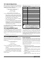
4.1
When configuration is complete, press the Exit or Save
and Exit softkey to exit setup mode, then replace the
setup switch access screw.
• The Exit softkey exits setup mode without saving
parameter changes to NV RAM. Changes made
to the configuration remain in the system until
indicator power is cycled.
• Save and Exit writes all parameter changes to NV
RAM before returning to normal mode.
Configuration Methods
The 920i indicator can be configured by using the front
panel keys to navigate through a series of configuration
menus or by sending commands or configuration data
to an indicator serial port. Configuration using the
menus is described in Section 4.1.3.
Configuration using the serial port can be
accomplished using either the serial command set or
the iRev configuration utility.
Some configuration parameters, such as those
Note used to configure the 920i display and widgets,
cannot be accessed through the configuration
menus. iRev provides the most complete and
efficient configuration interface for the 920i.
4.1.1
iRev Configuration
The iRev configuration utility provides the preferred
method for configuring the 920i indicator. iRev runs on
a personal computer to set configuration parameters for
the indicator. When iRev configuration is complete,
configuration data is downloaded to the indicator.
All configuration parameters can be set up
Note using iRev except configuration parameters
associated with the iQube. Those parameters
must be set up manually which is explained in
further detail in Section 4.2.2.
iRev supports both uploading and downloading of
indicator configuration data. This capability allows
configuration data to be retrieved from one indicator,
edited, then downloaded to another indicator with an
identical hardware configuration.
22
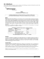
CLS-920i Installation Manual
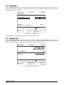
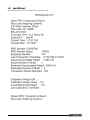
Figure 4-1. iRev Hardware Configuration Display
To use iRev, do the following:
1. Install iRev on an IBM-compatible personal
computer. See Section 5.0 on page 50 for
detailed hardware and software requirements.
2. With both indicator and PC powered off,
connect the PC serial port to the RS-232 pins
on the indicator serial port.
3. Power up the PC and the indicator. Use the
setup switch to place the indicator in setup
mode.
4. Start the iRev program.
iRev provides online help for each of its configuration
displays. Parameter descriptions provided in this manual
for front panel configuration can also be used when
configuring the indicator using iRev: The interface is
different, but the parameters set are the same.
See Section 6.4 for more information about using iRev to
configure the 920i.
4.1.2
Serial Command Configuration
The serial command set can be used to configure the
920i indicator using either a personal computer,
terminal, or remote keyboard. Like iRev , serial
command configuration sends commands to the
indicator serial port; unlike iRev, serial commands can
be sent using any external device capable of sending
ASCII characters over a serial connection.
Serial commands duplicate the functions available
using the indicator front panel and provide some
functions not otherwise available. Serial commands
can be used to simulate pressing front panel keys, to
configure the indicator, or to dump lists of parameter
settings.
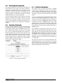
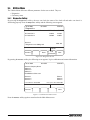
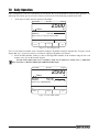
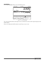
4.1.3
Front Panel Configuration
Use the CONFIG submenu under the SCALES menu
to configure A/D scales. For example, in an indicator
with a single-channel A/D card installed in Slot 1, the
Scale Configuration display will show the A/D listed
(Slot 1 Channel 1) under the AVAILABLE A/D’s column. Use
the left navigation key to select the A/D, then press the
center softkey, Add . The A/D is then moved to the
Associated A/D’s column. If no other A/D’s are listed
in the AVAILABLE A/D’s column, the center softkey
changes to Done, as shown in Figure 4-2. Press Done to
exit the Scale Configuration display..
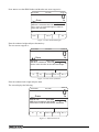
4.1.4
Total Scale Configuration
The output of two or more A/D scales or iQUBE
systems can be configured to function as a total scale.
Once configured and calibrated, the total scale can be
sued as a source for other system functions, including
streaming, setpoints, print formatting, and analog
output.
To set up a total scale from the indicator front panel,
use the scale configuration display (see Figure 4-2) to
select the A/D scales or iQUBE systems to configure as
a total scale. (Use the Change Type softkey to show
available A/D scales or iQUBE systems; use the right
navigation key to select the total scale sources.) In
iRev, assign the total scale to an unused position then
select source scales from the existing A/D scales or
iQUBE systems.
The FORMAT configuration of the total scale (see
Figure 4-5 on page 28) should match that of the source
scales. However, the value specified for the total scale
GRADS parameter should be specified as the sum of
the GRADS values for the source scales. For example:
if SCALE 1 is set to GRADS=10000, SCALE 2 to
GRADS=5000, SCALE 3 (the total scale) should be set
to 15000 grads.
The total scale will show an overrange indication if the
maximum capacity of any source scale is exceeded,
and show dashes if any source scale reads a negative
value. Source scales will respond to Tare and Zero
operations performed on the total scale.
Figure 4-2. Scale Configuration Display
CLS-920i Installation Manual
23
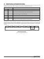
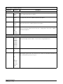
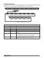
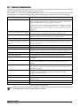
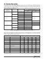
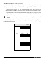
4.2
Menu Structures and Parameter Descriptions
The 920i indicator can be configured using a series of menus accessed through the indicator front panel when the
indicator is in setup mode. Table 4-1 summarizes the functions of each of the main menus.
Menu
Menu Function
SCALES
Configuration
Configure and calibrate scales.
SERIAL
Serial
Configure communications ports.
FEATURE
Feature
Set date and time formats, truck mode, passwords, keyboard locks, regulatory mode, and
initial consecutive number value, define softkeys and setpoint prompts.
PFORMT
Print Format
Set print format used for header, gross, net, truck in/out, setpoint, and auxiliary ticket formats.
See Section 6.0 on page 53 for more information.
SETPTS
Setpoints
Configure setpoints and batching mode.
DIG I/O
Digital I/O
Assign digital input/output functions.
ALGOUT
Analog Output
Configure analog output module. Used only if analog output option is installed.
VERSION
Version
Display installed software version number. The Reset Config softkey on the Version menu can
be used to restore all configuration parameters to their default values.
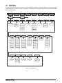
Table 4-1. 920i Menu Summary
The following sections provide graphic representations of the 920i menu structures and tables describing the menu
parameters. Default values are shown in bold type; numeric ranges and string values are shown in italic type.
Parameters shown surrounded by a dotted-line box only appear under the special circumstances explained under
each box.
4$"-&4
4&3*"-
'&"563&
1'03.5
4&5154
%*(*0
"-(065
4IPXOPOMZJG
"OBMPH0VUQVU
DBSEJTJOTUBMMFE
Figure 4-3. Configuration Menu Flow
24
CLS-920i Installation Manual
7&34
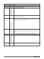
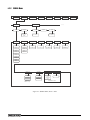
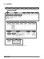
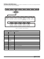
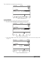
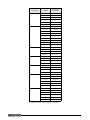
4.2.1
SCALES Menu
The SCALES menu is shown in Figure 4-4. The FORMAT submenu is shown in Figure 4-5 on page 28; the
CALIBR submenu is shown in Figure 4-6 on page 32. Parameters shown in each diagram are described in the table
following that diagram.
4$"-&4
4&3*"-
'&"563&
4$"-&Y
(3"%4
OVNCFS
4&5154
%*(*0
"-(065
7&34
;3"/(&
.05#"/%
445*.&
073-0"%
8.55)3)
0''
%
%
%
$0/'*(
;53,#/%
'03."5
GPS$-4
1'03.5
4FF
'03."5
4VCNFOV
GPS$-4
OVNCFS
'4
'4%
OVNCFS
%
%
'4%
%
%
%
'4
%
%
%
%
0''
%*('-5
%*('-5
%*('-5
%'4&/4
%'5)3)
3"553"1
4.13"5
065
/0/&
0''
);
065
%
0/
);
065
%
);
065
%
);
065
%
);
065
%
);
065
%
);
GPS$-4
GPS$-4
GPS$-4
%
);
%
18361.%
5"3&'/
"$$6.
(0
#05)
0''
0/
%&-":
/05"3&
0/
0''
1#5"3&
7*4*#-&
$"-*#3
4FF
$"-*#3
4VCNFOV
,&:&%
Figure 4-4. SCALES Menu
CLS-920i Installation Manual
25
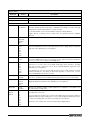
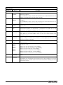
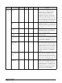
SCALES Menu
Parameter
Choices
Description
Level 2 submenus
SCALEx
Allows configuration and calibration of each scale
CONFIG
Lists available and associated A/Ds
Level 3 submenus
GRADS
1000
1–9999999
Specifies the number of full scale graduations.
The value entered must be in the range 1–9999999 and should be consistent with legal
requirements and environmental limits on system resolution.
To calculate GRADS, use the formula, GRADS = Capacity / Display Divisions.
Display divisions for primary and secondary units are specified under the FORMAT
submenu.
FORMAT
PRIMAR
SECNDR
TERTIA
ROC
See Level 4 submenu descriptions in Table 4-3 on page 29.
ZTRKBND
OFF
0.5D
1D
3D
5D
10D
20D
Automatically zeroes the scale when within the range specified, as long as the input is
within the ZRANGE and scale is at standstill. Selections are ± display divisions. Maximum
legal value varies depending on local regulations.
ZRANGE
1.9%
100%
Selects the range within which the scale can be zeroed. The 1.9% selection is ± 1.9%
around the calibrated zero point, for a total range of 3.8%. Indicator must be at standstill to
zero the scale. Use 1.9% for legal-for-trade applications.
MOTBAND
1D
2D
3D
5D
10D
20D
OFF
Sets the level, in display divisions, at which scale motion is detected. If motion is not
detected for 1 second or more, the standstill symbol lights. Some operations, including
print, tare, and zero, require the scale to be at standstill. Maximum legal value varies
depending on local regulations.
SSTIME
2
number
Specifies the length of time the scale must be out of motion, in 0.1-second intervals, before
the scale is considered to be at standstill. Values greater than 10 are not recommended.
OVRLOAD
FS+2%
FS+1D
FS+9D
FS
Determines the point at which the display blanks and an out-of-range error message is
displayed. Maximum legal value varies depending on local regulations.
WMTTHRH
1000
number
Specifies the minimum number of grads required for a weighment to be added to the
recorded number of weighments.
DIGFLT1
DIGFLT2
DIGFLT3
1
2
4
8
16
32
64
128
256
Selects the digital filtering rate used to reduce the effects of mechanical vibration from the
immediate area of the scale.
If this parameter is set to OFF, the standstill annunciator does not light; operations normally
requiring standstill (zero, tare, print) are performed regardless of scale motion. If OFF is
selected, ZTRKBND must also be set to OFF.
Choices indicate the number of A/D conversions per update that are averaged to obtain the
displayed reading. A higher number gives a more accurate display by minimizing the effect
of a few noisy readings, but slows down the settling rate of the indicator.
See Section 10.9 on page 119 for more information about digital filtering.
Table 4-2. SCALES Menu Parameters
26
CLS-920i Installation Manual
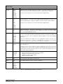
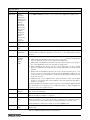
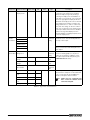
SCALES Menu
Parameter
DFSENS
DFTHRH
Choices
Description
2OUT
4OUT
8OUT
16OUT
32OUT
64OUT
128OUT
Digital filter cutout sensitivity. Specifies the number of consecutive readings that must fall
outside the filter threshold (DFTHRH parameter) before digital filtering is suspended.
NONE
2D
5D
10D
20D
50D
100D
200D
250D
Digital filter cutout threshold. Specifies the filter threshold, in display divisions. When a
specified number of consecutive scale readings (DFSENS parameter) fall outside of this
threshold, digital filtering is suspended. If NONE is selected, the filter is always enabled.
See Section 10.9 on page 119 for more information about digital filtering.
See Section 10.9 on page 119 for more information about digital filtering.
RATTRAP
OFF
ON
Enables RATTLETRAP® digital filtering. RATTLETRAP is most effective at filtering repeating
vibrations caused by mechanical noise from nearby machines but may increase settling
times over standard digital filter selections.
SMPRAT
120HZ
240HZ
480HZ
960HZ
7.5HZ
15HZ
30HZ
60HZ
Sample rate. Selects measurement rate, in samples per second, of the analog-to-digital
converter. Lower sample rate values provide greater signal noise immunity: the default 120
Hz value may be too fast to provide the desired stability in some static weighing
applications.
GO
DELAY
Power up mode. In GO mode, the indicator goes into operation immediately after a brief
power up display test.
PWRUPMD
NOTE: The maximum total sample rate for all configured A/D channels—the sum of the
sample rates for all scales—is 1200 Hz. For example, up to ten scales can be configured
with 120 Hz sample rates, or up to twenty scales with 60 Hz sample rates.
In DELAY mode, the indicator performs a power up display test, then enters a 30-second
warm up period. If no motion is detected during the warm up period, the indicator becomes
operational when the warm up period ends; if motion is detected, the delay timer is reset
and the warm up period repeated.
TAREFN
BOTH
NOTARE
PBTARE
KEYED
Enables or disables push-button and keyed tares. Possible values are:
BOTH: Both push-button and keyed tares are enabled
NOTARE: No tare allowed (gross mode only)
PBTARE: Push-button tares enabled
KEYED: Keyed tare enabled
ACCUM
OFF
ON
Accumulator. Specifies whether the scale accumulator is enabled. If enabled, accumulation
occurs whenever a print operation is performed.
VISIBL
ON
OFF
Scale visibility. Specifies whether scale data is displayed.
CALIBR
WZERO
WVAL
WSPAN
WLIN
REZERO
See Level 4 submenu descriptions in Table 4-6 on page 32.
Table 4-2. SCALES Menu Parameters (Continued)
CLS-920i Installation Manual
27
y
(3"%4
'03."5
;53,#/%
13*."3
;3"/(&
y
.05#"/%
4&$/%3
%&$1/5
%41%*7
6/*54
%&$1/5
%41%*7
6/*54
.6-5
%
-#
%
,(
%
,(
%
(
OVNCFS
%GPS$-4
(
%
0;
0;
5/
5
5
(/
(/
530:0;
530:0;
530:-#
530:-#
5/
-5
-5
$6450.
$6450.
0''
0''
/0/&
/0/&
-#
5&35*"
30$
%&$1/5
%41%*7
6/*54
.6-5
%&$1/5
%41%*7
.6-5
%
,(
%
%
(
OVNCFS
%
OVNCFS
%
0;
%
5/
5
(/
530:0;
530:-#
-5
$6450.
0''
/0/&
-#
5*.&
.*/
OVNCFS
OVNCFS
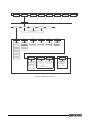
Figure 4-5. SCALES Menu, FORMAT Submenu
CLS-920i Installation Manual
3&'3&4)
4&$
)063
28
*/5&37-
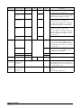
SCALES Menu, FORMAT Submenu
Parameter
Choices
Description
Level 4, FORMAT submenu
PRIMAR
DECPNT
DSPDIV
UNITS
Specifies the decimal position, display divisions, and units used for the primary units. See
Level 5 submenu parameter descriptions.
SECNDR
DECPNT
DSPDIV
UNITS
MULT
Specifies the decimal position, display divisions, units, and conversion multiplier used for the
secondary units. See Level 5 submenu parameter descriptions.
TERTIA
DECPNT
DSPDIV
UNITS
MULT
Specifies the decimal position, display divisions, units, and conversion multiplier used for the
tertiary units. See Level 5 submenu parameter descriptions.
ROC
DECPNT
DSPDIV
MULT
TIME
INTERVL
REFRESH
Specifies the decimal position, display divisions, conversion multiplier, time units, update
interval, and refresh interval used for the rate of change units. See Level 5 submenu
parameter descriptions.
Level 5 submenus
Primary Units (PRIMAR) Parameters
DECPNT
8888888
8888880
8888800
8.888888
88.88888
888.8888
8888.888
88888.88
888888.8
Decimal point location. Specifies the location of the decimal point or dummy zeroes in the
primary unit display. Value should be consistent with local legal requirements.
DSPDIV
1D
2D
5D
Display divisions. Selects the minimum division size for the primary units displayed weight.
UNITS
LB
KG
G
OZ
TN
T
GN
TROYOZ
TROYLB
LT
CUSTOM
NONE
OFF
Specifies primary units for displayed and printed weight. Values are: LB=pound;
KG=kilogram; G=gram; OZ=ounce; TN=short ton; T=metric ton; GN=grain; TROYOZ=troy
ounce; TROYLB=troy pound; LT=long ton.
Table 4-3. SCALES Menu, FORMAT Submenu Parameters
CLS-920i Installation Manual
29
SCALES Menu, FORMAT Submenu
Parameter
Choices
Description
Secondary Units (SECNDR) and Tertiary Units (TERTIA) Parameters
DECPNT
888888.8
8888888
8888880
8888800
8.888888
88.88888
888.8888
8888.888
88888.88
Decimal point location. Determines the location of the decimal point or dummy zeros in the
secondary or tertiary units display.
DSPDIV
2D
5D
1D
Display divisions. Selects the value of minimum division size of the displayed weight for
secondary or tertiary units display.
UNITS
KG
G
OZ
TN
T
GN
TROYOZ
TROYLB
LT
CUSTOM
OFF
NONE
LB
Specifies secondary or tertiary units for displayed and printed weight. Values are:
LB=pound; KG=kilogram; G=gram; OZ=ounce; TN=short ton; T=metric ton; GN=grain;
TROYOZ=troy ounce; TROYLB=troy pound; LT=long ton.
MULT
0.453592
0.000001–
9999999
Multiplier. Specifies the conversion factor by which the primary units are multiplied by to
obtain the secondary or tertiary units. The default is 0.453592, which is the conversion
factor for changing pounds to kilograms. See Section 10.10 on page 120 for a list of
multipliers.
To shift between primary, secondary, and tertiary units, press the UNITS key.
Rate of Change (ROC) Units Parameters
DECPNT
8888888
8888880
8888800
8.888888
88.88888
888.8888
8888.888
88888.88
888888.8
Decimal point location. Determines the location of the decimal point or dummy zeros in the
display.
DSPDIV
1D
2D
5D
Display divisions. Selects the minimum division size for the ROC units displayed weight.
Table 4-3. SCALES Menu, FORMAT Submenu Parameters (Continued)
30
CLS-920i Installation Manual
SCALES Menu, FORMAT Submenu
Parameter
MULT
Choices
1.0
0.000001–
9999999
Description
Multiplier. Specifies the conversion factor by which the primary units are multiplied by to
obtain the displayed rate of change units.
To calculate the MULT value, use the following equation:
MULT = (SMPRAT / INTERVL) * (seconds_per_ROC_unit) * (ROC/PRIMAR_precision_adjustment)
Where:
• SMPRAT is the value specified for the A/D sample rate on the SCALES menu
• INTERVL is the specified ROC interval
• seconds_per_ROC_unit is an adjustment for the ROC UNITS parameter. If ROC UNITS
is set to SEC, use 1; use 60 for UNITS=MIN, use 3600 for UNITS=HOUR.
• ROC/PRIMAR_precision_adjustment compensates for any difference in the DECPNT
and DSPDIV parameters specified for primary units and ROC units. For example, if the
ROC DECPNT parameter is set to 8888888 (no decimal) and with DSPDIV=1, ROC
precision is 1. If PRIMAR DECPNT is set to 8888880 (null units position) and
DSPDIV=2, PRIMAR precision is 20. (That is, weights will be displayed in increments of
20.) In this example, the precision adjustment would be 1 / 20, or 0.05.
Example: If SMPRAT=120HZ, INTERVL=240, ROC UNITS=MIN, and the precision is
compensated as described above, MULT would be calculated as follows:
MULT = (120 / 240) * 60 * 0.05 = 1.5
To calculate a ROC MULT value based on secondary or tertiary units, multiply the calculated
primary units MULT value by the conversion factor for the alternate units. For example, if a
MULT value of 1.5 is calculated for pounds as the primary unit, calculate the MULT value for
kilogram secondary units by multiplying the original MULT value by 0.453592:
MULT(kg) = 1.5 * 0.453592 = 0.680388
See Section 10.10 on page 120 for information about conversion factors.
TIME
SEC
MIN
HOUR
Rate-of-change units.
INTERVL
10
1–100
Update interval. Specifies the number of refreshes over which the rate-of-change is
calculated.
REFRESH
0.1
0.1–60
Refresh interval. Specifies the number of seconds between rate-of-change samples. The
value specified for this parameter should be an integer not less than 1% and not more than
50% of the update interval (INTERVL parameter) specified. For example, if the INTERVL
parameter value is 100, the REFRESH specified should be in the range of 1.2–60.
Table 4-3. SCALES Menu, FORMAT Submenu Parameters (Continued)
CLS-920i Installation Manual
31
y
7*4*#-&
y
$"-*#3
(3"%4
'03."5
8;&30
87"-
841"/
8-*/
3&;&30
10*/5
10*/5
10*/5
10*/5
10*/5
Figure 4-6. SCALES Menu, CALIBR Submenu
For the CLS Series Cargo Lift Scale, do not use this section as reference for calibration. Please refer to. Section
Note 6.0 for complete calibration instructions.
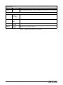
SCALES Menu, CALIBR Submenu
Parameter
Choices
Description
Level 4, CALIBR submenu
WZERO
—
Press ENTER to display and edit the zero calibration A/D count or millivolts value.
WVAL
—
Press ENTER to display and edit the test weight value.
WSPAN
—
Press ENTER to display and edit the span calibration A/D count or millivolts value.
WLIN
POINT 1 —
POINT 5
Press ENTER to display and edit test weight and calibration values for up to five linearization points.
—
Press ENTER to remove an offset value from the zero and span calibrations.
REZERO
Perform linear calibration only after WZERO and WSPAN have been set.
Note
Use this parameter only after WZERO and WSPAN have been set.
Table 4-4. SCALES Menu, CALIBR Submenu Parameters
32
CLS-920i Installation Manual
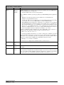
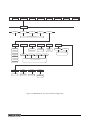
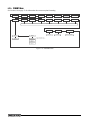
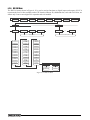
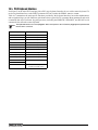
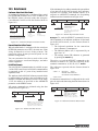
4.2.2
SERIAL Menu
4$"-&4
4&3*"-
'&"563&
1035
$.%
1'03.5
4&5154
%*(*0
"-(065
…
1035
130(*/
130(*/
4BNFBT
$.%
4FF1035
,&:#%
$.%
4FF1035
#"6%
#*54
5&3.*/
4501#*54
/0/&
$3-'
0/
0/
&7&/
$3
0''
0''
OVNCFS
0%%
0%%
&7&/
7&34
&$)0
3&410/4&
&0-%-:
)"/%4),
453&".
4063$&
4'.5
-JTUPG
DPOmHVSFE
TDBMFT
GPSNBU
0''
0''
90/90''
-'5
)3%8"3
*/%645
)3%8"3PO
1035POMZ
*G453&".ò0''
Figure 4-7. SERIAL Menu, Ports 1 and 2
CLS-920i Installation Manual
33
4$"-&4
4&3*"-
'&"563&
1'03.5
4&5154
%*(*0
"-(065
…
1035
130(*/
$.%
4$"-&
*/%4$
*26#&
&0-%-:
4FF130(*/4FMFDUJPOT
#"6%
#*54
5&3.*/
4501#*54
/0/&
$3-'
0''
&7&/
$3
OVNCFS
90/90''
453&".
4063$&
4'.5
0''
-JTUPG
DPOmHVSFE
TDBMFT
GPSNBU
0%%
0%%
&7&/
)"/%4),
-'5
*/%645
*G453&".ò0''
*G1035
$.%PS130(*/
Figure 4-8. SERIAL Menu, Port 3
34
7&34
CLS-920i Installation Manual
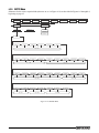
4'.5
GPSNBU
*G1035
4$"-&PS*/%4$
4$"-&4
4&3*"-
'&"563&
1'03.5
4&5154
%*(*0
"-(065
…
1035
130(*/
$.%
7&34
4$"-&
*/%4$
*26#&
4&$5*0/
1-"5'.
4:45&.
"-(065
1"*3&%
$*3$6-"3
"TTJHODFMMT
UPQMBUGPSNT
"TTJHO
QMBUGPSNT
UPTZTUFNT
4063$&
4FF130(*/4FMFDUJPOT
$0/'*(
$&--4
'6--4$
90/90''
-FBWFBUEFGBVMUTFUUJOHT
$&--"
$&--"
$&--"
$&--"
-FBWFBUEFGBVMUTFUUJOHT
%*(*0
*2%*"(
5&45$0.
10355:1&
-FBWFBU%FGBVMU
-FBWFBU%FGBVMU
7"-*%"5
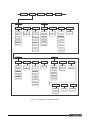
Figure 4-9. SERIAL Menu, Port 4 for CLS-920i Configuration
CLS-920i Installation Manual
35
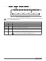
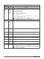
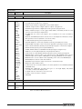
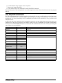
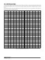
SERIAL Menu
Parameter
Choices
Description
Level 2 submenus
PORT 1
PORT 2
PORT 3
PORT 4
…
PORT x
CMD
PROGIN
KEYBD
SCALE
IND SC
IQUBE
Specifies the type of data received by the port:
CMD:
Remote command input
PROGIN: Programmable input
KEYBD: Remote keyboard input
SCALE: Legal-for-trade serial scale input
IND SC: Industrial (non-legal-for-trade) scale input
IQUBE: iQUBE serial scale input
KEYBD is available only on Port 2; SCALE, IND SC, IQUBE, and HIPREC are available only on
Ports 3 and 4 and higher (expansion ports).
Note
The keyboard interface is not hot-pluggable. Power-off the 920i before
plugging the keyboard cable into the Port 2 connector.
Level 3 Submenus
Port 1–Port 32
CONFIG
4/0/0/0
8/0/0/0
8/4/0/0
8/4/4/0
8/8/0/0
4/4/0/0
4/4/4/0
4/4/4/4
4/8/0/0
iQube board configuration.
CELLS
CELLA1
CELLA2
CELLA3
CELLA4
iQube load cell configuration
SECTION
PAIRED
CIRCULAR
iQube section definition
PLATFRM
A1
A2
iQube platform definition
SYSTEM
PLATFRM1
iQube platform definition
ALGOUT
SOURCE
FULLSC
iQube analog output definition
DIGIO
iQube digital I/O configuration
Leave at
default setting
IQDIAG
iQube diagnostics parameter
Leave at
default setting
TESTCOM
VALIDATE
iQube communications tester
PORTTYPE
232
485
Specifies whether Port 4 is used for RS-232 or RS-485 communications. If 485 is selected,
additional prompts are shown to specify half- or full-duplex operation and RS-485 address.
Note
RS-485 communications can be specified for Port 4, and for odd numbered
expansion ports 5 and higher.
Table 4-5. CLS-920i Serial Menu Parameters
36
CLS-920i Installation Manual
4.2.3
FEATURE Menu
4$"-&4
4&3*"-
'&"563&
%"5&
1'03.5
5*.&
%"5&'.5
%"5&4&1
5*.&'.5
5*.&4&1
..%%::::
4-"4)
)063
$0-0/
%%..::::
%"4)
)063
$0.."
::::..%%
4&.*
4&5154
%*(*0
"-(065
7&34
%&$'.5
%413"5&
$0/4/6.
$0/4561
%05
$0.."
OVNCFS
OVNCFS
OVNCFS
::::%%..
6*%
536$,
$'(18%
4118%
40'5,&:4
,:#%-,
;&30/-:
-JTUTPG
BWBJMBCMFBOE
DPOmHVSFE
TPGULFZT
0''
0''
0/
0/
0''
VOJU@*%
.0%&
OVNCFS
OVNCFS
.0%&
.0%&
.0%&
.0%&
.0%&
3&(6-"5
130.154
3&(803%
/5&1
130.15
y
130.15
$"/"%"
*/%645
TUSJOH
TUSJOH
/0/&
$0/5"$5
(3044
4FF
*/%645
4VCNFOV
#36550
4FF
$0/5"$5
4VCNFOV
0*.-
-0$"-&
-"56%&
&-&7"5
0''
0/
OVNCFS
OVNCFS
*G-0$"-&0/
Figure 4-10. FEATURE Menu
CLS-920i Installation Manual
37
FEATURE Menu
Parameter
Choices
Description
Level 2 submenus
DATE
DATEFMT
DATESEP
Allows selection of date format and date separator character. See Level 3 submenu
parameter descriptions.
Use the TIME/DATE softkey or the SD serial command to set the date. See Section 9.0 on
page 80 for information about using the serial commands.
TIME
TIMEFMT
TIMESEP
Allows selection of time format and separator character. See Level 3 submenu parameter
descriptions.
Use the TIME/DATE softkey or the ST serial command to set the time. See Section 9.0 on
page 80 for information about using the serial commands.
DECFMT
DOT
COMMA
Specifies whether decimal numbers are displayed using a period (DOT) or comma as the
decimal symbol.
DSPRATE
1
1–80
Display update rate. Specifies the display update rate, in the number of 100-millisecond
intervals between updates. The default value, 1, provides about 10 updates per second.
The maximum value updates the display every 8 seconds.
CONSNUM
0
0–9999999
Consecutive numbering. Allows sequential numbering for print operations. The consecutive
number value is incremented following each print operation that includes <CN> in the ticket
format. When the consecutive number is reset, it is reset to the value specified on the
CONSTUP parameter.
CONSTUP
0
0–9999999
Specifies the consecutive number start-up value used when the consecutive number is
reset by sending the KCLRCN serial command or a CLRCN digital input. Value specified
must be in the range 0–9 999 999.
UID
1
unit-ID
Specifies the unit identification number. Value specified can be any alphanumeric value, up
to eight characters.
TRUCK
OFF
MODE1
MODE2
MODE3
MODE4
MODE5
MODE6
Specifies the truck mode used. If selected, the indicator switches from normal mode to the
selected truck mode.
CFGPWD
0
0–9999999
Configuration password. Specify a non-zero value to restrict access to all configuration
menus.
SPPWD
0
0–9999999
Setpoint password. Specify a non-zero value to restrict access to the setpoint menu.
MODE1: Auto clear ID, keyed tares, value swapping
MODE2: Auto clear ID, no keyed tares, value swapping
MODE3: Stored ID, keyed tares, value swapping
MODE4: Stored ID, no keyed tares, value swapping
MODE5: Stored ID, keyed tares, no value swapping
MODE6: Stored ID, no keyed tares, no value swapping
The SPPWD is also shared by, and can be used to protect, the truck register. If a non-zero
setpoint password is specified, the password must be entered before deleting any entries
from the truck register.
Table 4-6. FEATURE Menu Parameters
38
CLS-920i Installation Manual
FEATURE Menu
Parameter
Choices
Description
SOFTKEYS
<blank>
Time/Date
Display Tare
Display Accum
Display ROC
Setpoint
Batch Start
Batch Stop
Batch Pause
Batch Reset
Weigh In
Weigh Out
Truck Regs
Unit ID
Select Scale
F1–F10
Diagnostics
Use the Add and Remove softkeys to select softkeys to be displayed in weighing mode.
KYBDLK
OFF
ON
Keyboard lock. Specify ON to disable the keypad in normal mode.
ZERONLY
OFF
ON
Zero key only. Specify ON to disable all front panel keys except ZERO in normal mode.
PROMPTS
PROMPT1–
PROMPT60
Specify prompts for use in setpoint names. Prompts are referenced by the NAME parameter
under the SETPTS submenus; prompts can be shown on the display during setpoint
execution.
REGULAT
NTEP
CANADA
INDUST
NONE
OIML
Regulatory mode. Specifies the regulatory agency having jurisdiction over the scale site.
• OIML, NTEP, and CANADA modes allow a tare to be acquired at any weight greater
than zero. NONE allows tares to be acquired at any weight value.
• OIML, NTEP, and CANADA modes allow a tare to be cleared only if the gross weight is
at no load. NONE allows tares to be cleared at any weight value.
• NTEP and OIML modes allow a new tare to be acquired even if a tare is already
present. In CANADA mode, the previous tare must be cleared before a new tare can be
acquired.
• NONE, NTEP and CANADA modes allow the scale to be zeroed in either gross or net
mode as long as the current weight is within the specified ZRANGE. In OIML mode, the
scale must be in gross mode before it can be zeroed; pressing the ZERO key in net
mode clears the tare.
• INDUST provides a set of subparameters to allow customization of tare, clear, and print
functions in non-legal-for-trade scale installations. See Level 4 parameter descriptions
in Table 4-8 on page 42.
The value specified for this parameter affects the function of the front panel TARE and ZERO
keys. See Section 10.2 on page 108 for a complete description of TARE and ZERO key
functions for each of the regulatory modes.
REGWORD
GROSS
BRUTTO
Sets the term displayed when weighing in gross mode. Selecting BRUTTO replaces the
Gross annunciator with Brutto.
CONTACT
—
Allows specification of contact information for use in iQUBE alert messages. See Level 3
submenu descriptions in Table 4-7 on page 41.
LOCALE
OFF
ON
Locale. Set this parameter ON to enable the LATUDE and ELEVAT parameters. Specifying
latitude and elevation of the scale site provides compensation for gravitational effects.
Attached scales must be recalibrated after changing this parameter from OFF to ON.
NOTE: Gravitational compensation settings do not affect iQUBE scales.
LATUDE
45
0–90
Latitude. Specify the latitude of the scale site in degrees. This parameter is shown only if
LOCALE=ON.
Table 4-6. FEATURE Menu Parameters (Continued)
CLS-920i Installation Manual
39
FEATURE Menu
Parameter
ELEVAT
Choices
345
±0–9999
Description
Elevation. Specify the elevation of the scale site in meters. Valid values are –9999 through
9999. This parameter is shown only if LOCALE=ON.
Level 3 submenus
DATEFMT
MMDDYYYY
DDMMYYYY
YYYYMMDD
YYYYDDMM
Specifies the format used to display or print the date.
DATESEP
SLASH
DASH
SEMI
Specifies the date separator character.
TIMEFMT
12HOUR
24HOUR
Specifies the format used to display or print the time.
TIMESEP
COLON
COMMA
Specifies the time separator character.
Table 4-6. FEATURE Menu Parameters (Continued)
40
CLS-920i Installation Manual
FEATURE Menu, CONTACT Submenu
The CONTACT submenu allows entry of contact information for a contact company or scale dealer. Contact
information can be displayed by pressing the Contacts softkey on the Version menu in setup mode or the
Diagnostics softkey when in weigh mode. Contact information may be used in print formats.
4$"-&4
4&3*"-
'&"563&
1'03.5
4&5154
%*(*0
"-(065
7&34
$0/5"$5
$.1/:
"%%3
"%%3
"%%3
/".&
/".&
/".&
DPNQBOZ@OBNF
BEESFTT@MJOF@
BEESFTT@MJOF@
BEESFTT@MJOF@
DPOUBDU@OBNF@
DPOUBDU@OBNF@
DPOUBDU@OBNF@
1)0/&
1)0/&
1)0/&
&."*-
/&95$"-
QIPOF@OVNCFS
QIPOF@OVNCFS
QIPOF@OVNCFS
FNBJM@BEESFTT
EBUF
Figure 4-11. CONTACT Submenu
FEATURE Menu, CONTACT Submenu
Parameter
Choices
Description
Level 3, CONTACT submenu
CMPNY
company_name
Enter the name of the contact company or dealer.
ADDR1–ADDR3
address
Enter up to three lines of address information for the contact company.
NAME1–NAME3
contact_name
Enter names of up to three contact persons.
PHONE1–PHONE3
phone_number
Enter phone numbers for each of the contact persons specified for the NAMEx
parameter.
EMAIL
email_address
Enter the e-mail address of the contact company or dealer.
If the iQUBE alert support is used to send automated alert e-mail messages,
enter the e-mail address to which the alert messages will be sent.
NEXTCAL
date
Enter the next scheduled calibration date using the month/day/year format on the
DATEFMT parameter. Separator characters are not required.
Table 4-7. CONTACT Submenu Parameters
CLS-920i Installation Manual
41
FEATURE Menu, REGULAT/INDUST Submenu
The INDUST setting of the REGULAT parameter allows customization of several tare, clear, and print functions
for use in non-legal-for-trade scale installations.
4$"-&4
4&3*"-
'&"563&
1'03.5
4&5154
%*(*0
"-(065
;5"3&
,5"3&
.5"3&
/5"3&
$5"3&
3&(6-"5
*/%645
4/14)05
)5"3&
%*41-":
/0
/0
:&4
3&1-"$&
:&4
/0
4$"-&
:&4
:&4
/0
3&.07&
/0
:&4
/05)*/(
135.05
13515
135)-%
)-%8()
.058()
/0
/0
/0
/0
/0
:&4
:&4
:&4
:&4
:&4
Figure 4-12. REGULAT / INDUST Submenu
FEATURE Menu, REGULAT / INDUST Submenu
Parameter
Choices
Description
Level 4, REGULAT / INDUST submenu
SNPSHOT
DISPLAY, SCALE
Display or Scale weight source.
HTARE
NO, YES
Allow tare in display hold
ZTARE
NO, YES
Remove tare on ZERO
KTARE
YES, NO
Always allow keyed tare
MTARE
REPLACE,
REMOVE,
NOTHING
Multiple tare action
NTARE
NO, YES
Allow negative or zero tare
CTARE
YES, NO
Allow CLEAR key to clear tare/accumulator
PRTMOT
NO, YES
Allow print while in motion
PRTPT
NO, YES
Add PT to keyed tare print
PRTHLD
NO, YES
Print during display hold
HLDWGH
NO, YES
Allow truck weighment during display hold
MOTWGH
NO, YES
Allow truck weighment in motion
Table 4-8. REGULAT / INDUST Submenu Parameters
42
CLS-920i Installation Manual
7&34
4.2.4
PFORMT Menu
See Section 6.0 on page 53 for information about custom print formatting.
4$"-&4
4&3*"-
'&"563&
1'03.5
4&5154
%*(*0
"-(065
7&34
('.5
/'.5
"$$'.5
41'.5
538*/
538065
53'.5
"-&35
4BNFBT('.5
'.5
1035
GPSNBU
1035
)%3'.5
)%3'.5
"69'.5
GPSNBU
GPSNBU
4BNFBT('.5
/05&%FGBVMUQPSUGPS
"-&35GPSNBUJT1035
1035
1035
1035
Figure 4-13. PFORMT Menu
CLS-920i Installation Manual
43
4.2.5
SETPTS Menu
Submenus for the various setpoint kinds (shown as Go to X in Figure 4-14) are described in Figures 8-2 through 8-9,
beginning on page 65.
4$"-&4
4&3*"-
'&"563&
1'03.5
4&5154
%*(*0
"-(065
7&34
#"5$)/(
41$'(
4&515
y
4&515
0''
"650
."/6"-
0''
(3044
/&5
o(3044
o/&5
"$$6.
30$
3&43&-
1"64&
%&-":
(PUP"
3&-
o3&-
3&-
(PUP#
$0;
*/.050/
8"*544
$),8&*
*/3"/(&
1-4$/5
(PUP'
#"5$)13
5*.&3
$0/$63
%*(*/
CLS-920i Installation Manual
"7(
50%
(PUP&
1-43"5
(PUP(
"-8":4
/&7&3
(PUP)
Figure 4-14. SETPTS Menu
44
"650+0(
(PUP$
(PUP%
%&-5"
$06/5&3
%*/$/5
4.2.6
DIG I/O Menu
The DIG I/O menu shown in Figure 4-15 is used to assign functions to digital inputs and outputs. SLOT 0
represents the four I/O bits available on the CPU board (connector J2); additional slots, each with 24 I/O bits, are
shown only if one or more digital I/O expansion cards are installed.
4$"-&4
4&3*"-
1'03.5
4&5154
%*(*0
y
4-05
#*5
'&"563&
#*5
"-(065
7&34
4-05Y
#*5
#*5
#*5
4BNFBT#*5
y
#*5
4BNFBT4-05#*5
0''
,&:
*/165
,&:
)0-%
065165
,&:
#"536/
130(*/
,&:
#"54535
;&30
,&:
#"51"64
/5(34
,&:
#"53&4&5
5"3&
,&:
#"54501
6/*54
,&:
$-3$/
13*/5
,&:
(3044
"$$6.
,&:%1
/&5
4&51/5
,&:
13*.
5*.%"5&
&/5&3
4&$
&4$
/"761
5&3
$-&"3
/"7%/
$-35"3
,#%-0$
%415"3
/"7-'5
$-3"$$
*%,&:
/"73(5
53*((&3
0654-05
1"3".
/0/&
4-05
OVNCFS
Figure 4-15. DIG I/O Menu
CLS-920i Installation Manual
45
DIG I/O Menu
Parameter
Choices
Description
Level 2 submenus
SLOTx
BIT y
Lists available digital I/O slots.
Level 3 submenus
BIT y
OFF
INPUT
OUTPUT
PROGIN
ZERO
NT/GRS
TARE
UNITS
PRINT
ACCUM
SETPNT
TIMDATE
ESC
CLEAR
DSPTAR
IDKEY
KEY0—KEY9
KEYDP
ENTER
NAVUP
NAVDN
NAVLFT
NAVRGT
KBDLOC
HOLD
BATRUN
BATSTRT
BATPAUS
BATRESET
BATSTOP
CLRCN
GROSS
NET
PRIM
SEC
TER
CLRTAR
CLRACC
TRIGGER
Specifies the function of the digital I/O bit.
•
•
•
•
•
•
•
•
•
•
•
•
•
•
•
•
•
•
•
•
•
•
•
•
•
•
OFF indicates that the bit is not configured.
INPUT assigns the bit as a digital input used for DIGIN setpoints.
OUTPUT assigns the bit as a digital output for setpoint or program use.
PROGIN assigns the bit as a digital input used to generate a program event.
ZERO, NT/GRS (net/gross mode toggle), TARE, UNITS, and PRINT provide the same
functions as the five major front panel keys.
ACCUM adds the current scale weight to the accumulator, if the scale accumulator is
enabled.
SETPNT, and TIMDATE provide the same functions as the Setpoint and Time/Date softkeys.
ESC provides a function equivalent to the Cancel softkey.
CLEAR simulates pressing the front panel CLR key.
DSPTAR displays the current tare; equivalent to pressing the Display Tare softkey.
IDKEY displays a prompt to enter a new unit ID; equivalent to pressing the Unit ID softkey.
KEY0—KEY9 and KEYDP (decimal point) simulate pressing keys on the numeric keypad.
ENTER simulates pressing the front panel ENTER key.
NAVUP, NAVDN, NAVLFT, and NAVRGT simulate pressing the navigation keys.
KBDLOC locks the keyboard (indicator front panel) when held low.
HOLD holds the current display. Releasing this input clears the running average filter.
BATRUN allows a batch routine to be started and run. With BATRUN active (low), the
BATSTRT input starts the batch; if BATRUN is inactive (high), BATSTRT resets the batch.
BATSTRT starts or resets a batch routine, depending on the state of the BATRUN input.
BATPAUS pauses a batch routine when held low.
BATRESET stops the batch sequence and resets to the first batch step.
BATSTOP stops the batch routine.
CLRCN resets the consecutive number to the value specified on the CONSTUP parameter
(FEATURE menu).
GROSS, NET, PRIM, SEC, and TER select gross or net weight display, and primary,
secondary, or tertiary units display modes.
CLRTAR clears the current tare for the active scale.
CLRACC clears the active accumulator.
TRIGGER
Level 4 submenus
TRIGGER subparameters
OUTSLOT
NONE
PORT 3
Specifies the card slot receiving the trigger output.
PARAM
0
number
Specifies the value passed as a parameter to the option card in the specified slot.
Table 4-9. DIG I/O Menu Parameters
46
CLS-920i Installation Manual
4.2.7
Analog Output Menu
The ALGOUT menu is shown only if the analog output option is installed. If the analog output option is installed,
configure all other indicator functions and calibrate the indicator itself before configuring the analog output. See
the Analog Output Card Installation Instructions, PN 69089, for more information.
4$"-&4
4&3*"-
'&"563&
1'03.5
4&5154
%*(*0
"-(065
7&34
4063$&
.0%&
0''4&5
&33"$5
.*/
."9
58;&30
5841"/
130(
(3044
'6--4$
4$"-&O
/&5
)0-%
OVNCFS
OVNCFS
OVNCFS
OVNCFS
*G4063$&ò130(
;&304$
Figure 4-16. Analog Output Menu
ALG OUT Menu
Parameter
Choices
Description
Level 2 submenus
SOURCE1
PROG
SCALEn
Specifies the scale tracked by the analog output. PROG indicates that the analog output is under
program control.
MODE1
GROSS
NET
Specifies the weight data, gross or net, tracked by the analog output.
OFFSET
0%
20%
Zero offset. Select 0% for 0–10 V or 0–20 mA output; select 20% for 4–20 mA output. This
parameter must be set before calibrating the analog output.
ERRACT
FULLSC
HOLD
ZEROSC
Error action. Specifies how the analog output responds to system error conditions.
Possible values are:
FULLSC: Set to full value (10 V or 20 mA)
HOLD: Hold current value
ZEROSC: Set to zero value (0 V or 4 mA)
MIN
000000
0–9999999
Specifies the minimum weight value tracked by the analog output. Specify a value in the range
0–9999999.
MAX
10000
0–9999999
Specifies the maximum weight value tracked by the analog output. Specify a value in the range
0–9999999
TWZERO
40
0–65535
Tweak zero. Enter tweak value to adjust the analog output zero calibration. Use a multimeter to
monitor the analog output value.
TWSPAN
59650
0-65535
Tweak span. Enter tweak value to adjust the analog output span calibration. Use a multimeter to
monitor the analog output value.
Table 4-10. Analog Output Menu Parameters
CLS-920i Installation Manual
47
4.2.8
Version Menu
The VERS menu can be used to check the installed software version or, by using the Reset Config softkey, to restore
all configuration parameters to their factory default values. There are no parameters associated with the Version
menu: when selected, the indicator displays the installed software version number.
4$"-&4
4&3*"-
'&"563&
1'03.5
4&5154
%*(*0
"-(065
7&34
4PGUXBSF
WFSTJPO
Figure 4-17. Version Menu
The Contacts softkey on the Version menu allows display of contact information (see “FEATURE Menu,
CONTACT Submenu” on page 41). If an iQUBE scale is configured, a Diagnostics softkey also provides access to
iQUBE diagnostic information.
48
CLS-920i Installation Manual
5.0 Configuration of User Parameters
The CLS-920i has many parameters that must be configured in order for the indicator software to work properly.
Once the indicator is configured for the basic scale parameters and is saved, the following main menu screen
appears.
4$"-&
".
(SPTT
MC
1JUDI #BUUFSZ-JGF)PVST
3PMM &NQ*%
130/VN
1MFBTFFOUFSPSTDBOZPVSFNQMPZFF*%
$BODFM
)PNF
&OE
Figure 5-1. CLS-920 Main Screen
Enter your employee ID or login using the numeric keypad on the 920i indicator and press the enter key. If the
employee ID is already in the CLS-920i database, the following screen appears.
(SPTT
&NQ*%
130/VN
130
/VNCFS
4$"-&
".
MC
1JUDI #BUUFSZ-JGF)PVST
3PMM &NQMPZFF
-PHPGG
.PSF
Figure 5-2. Employee Database Menu Screen
If the employee ID or login that is entered is a new ID, then the indicator will state that the ID Has Been Entered Into
available softkeys that can be
access additional parameters.
The Employee Database and then Figure 5-2 is displayed. At this point there are three
used to either Employee Logoff, enter the PRO Number or press the More => softkey to
CLS-920i Installation Manual
49
5.1
PRO Number
The PRO Number is an acronym for Progressive Rotating Order. A pro number is assigned to each shipment and
serves as a tracking number and a carrier invoice number. Select the PRO Number softkey to enter a pro number
and the following screen is displayed.
4$"-&
".
(SPTT
MC
&NQ*%
1JUDI #BUUFSZ-JGF)PVST
3PMM 130/VN
1MFBTFFOUFSB130/VNCFS
130
)PNF
$BODFM
&OE
Figure 5-3. PRO Screen
Enter the PRO number and press the enter key on the 920i. If it is not a valid PRO number, the indicator screen will
state that Entry not a valid PRO #.
Another attempt to enter a PRO number will occur and if a correct PRO number is not entered, Entry Mode Cancelled
will be displayed on the screen.
5.2
More =>
The More => softkey takes the user to another set of softkeys that can access various user program parameters. Press
the More => softkey to access the following list of additional softkeys on the 920i.
• Existing PRO Skid Count
• Calibration Check
• Utilities Menu
• Supervisor Menu
All of the above mentioned items are explained in further detail in the following sections.
An employee can access all of the softkeys that are programmed into the 920i user program other than the
Supervisor menu. That needs a password to access those additional parameters.
50
CLS-920i Installation Manual
5.3
Calibration Check
Press the Calibration Check softkey on the 920i to enter in a new calibration weight or keep the existing one if one
has already been entered.
4$"-&
".
(SPTT
MC
#BUUFSZ-JGF)PVST
&NQ*%
130/VN
1MFBTFFOUFSUIFUFTUXFJHIU*%
5FTU8U*%
)PNF
$BODFM
&OE
Figure 5-4. Calibration Check Screen
Enter a test weight ID number into the 920i and press enter. You are then asked to Enter Test Weight Amount using the
numeric keypad on the 920i. Enter that amount and press the enter key.
Then the following screen appears.
(SPTT
4$"-&
".
MC
#BUUFSZ-JGF)PVST
&NQ*%
130/VN
1SFTTA4UPSF/FX$BM$IFDLPSA&YJUUPBCPSU
4UPSF/FX
$BM$IFDL
&YJU
Figure 5-5. Store New Calibration Check Screen
Place the test weights on the forks of the scale at this time.
Press the Store New Cal Check softkey to store the new calibration check amount or press Exit to exit out of the
sequence. If the Store New Cal Check softkey is pressed the user is alerted that the New Calibration Check is Stored and
the screen goes back to the Main Menu screen.
CLS-920i Installation Manual
51
5.4
Utilities Menu
The Utilities Menu offers two different parameters for the user to check. They are:
• Diagnostics
• Get battery status
5.4.1
Diagnostics Softkey
By pressing the Diagnostics softkey, the user can check the status of the load cell and make sure that it is
functioning properly. Press the Diagnostics softkey and the following screen appears.
4$"-&
".
%JBHOPTUJDT
%&"%-0"%$633&/5
/".&
"-PBE$FMM
"-PBE$FMM
4ZTUFN
XFJHINFOUPWFSHSBET
$FMM0,
1SFWJPVT
%POF
$FMM
&NVMBUJPO
/FYU
Figure 5-6. Diagnostics Screen
By pressing the Previous softkey, the following screen appears. It gives calibration and contact information.
4$"-&
".
$POUBDU$PNQBOZ/BNF
"EESFTT
"EESFTT
"EESFTT
&NBJM"EESFTT!SMXTDPN
$POUBDU
$POUBDU
$POUBDU
1IPOF
1IPOF
1IPOF
-BTU$BMJCSBUJPO
/FYU4FSWJDF%VF
/FYU
1SFWJPVT
Figure 5-7. Calibration Contact Screen
Press the Previous softkey again to return back to the Main Menu screen.
52
CLS-920i Installation Manual
5.4.2
Cell Emulation
Press the Cell Emulation softkey to simulate actual current and weight running through the load cell. This is done to
check the load cells and see that they’re functioning properly. Figure 5-8 illustrates what the screen looks like if the
Cell Emulation softkey is pressed.
4$"-&
".
%JBHOPTUJDT
%&"%-0"%$633&/5
/".&
"-PBE$FMM
"-PBE$FMM
4ZTUFN
XFJHINFOUPWFSHSBET
$FMM0,
1SFWJPVT
$FMM
&NVMBUJPO
%POF
/FYU
Figure 5-8. Cell Emulation Screen
Press the Previous softkey again to return back to the Main Menu screen.
5.4.3 Get Battery Status
Press the Get Battery Status softkey to find out how much time is remaining on the forklift wireless junction box
battery. It is measured in hours is and briefly displayed on the screen when the Get Battery Status softkey is pressed.
If the CLS Cargo Lift Scale is a wired version, the Battery Life Remaining will show N/A.
4$"-&
".
(SPTT
MC
#BUUFSZ-JGF)PVST
&NQ*%
130/VN
#BUUFSZ-JGF3FNBJOJOH)PVST
%JBHOPTUJDT
(FU#BUUFSZ
4UBUVT
#BDLUP
.BJO.FOV
Figure 5-9. Battery Status Screen
CLS-920i Installation Manual
53
5.5
Supervisor Menu
Press the Supervisor Menu softkey to gain access to application parameters and other settings.Upon pressing that
softkey the operator is asked to enter a password.
4$"-&
".
(SPTT
MC
#BUUFSZ-JGF)PVST
&NQ*%
130/VN
&OUFS1BTTXPSE
&YJU
Figure 5-10. Supervisor Menu
The default password is 0 and the user will not be asked to enter a password when the password is 0. In effect,
leaving the password at 0 (zero) disables password protection. Select Password from near the bottom of the
Supervisor Menu list to change the password.
".
4$"-&
4FMFDU$BUFHPSZ
"QQ1BSBNFUFST
3FQPSU)FBEFS*OGPSNBUJPO
$BMJCSBUJPO$IFDL7BMVFT
4FSJBM1PSUT
*OUFSWBMT
$MPDL
1BTTXPSE
;FSP*ODMJOPNFUFS
$MFBS1305SBOT%BUBCBTF
"QQ1BSBNFUFST
&YJU
Figure 5-11. Supervisor List
The Supervisor Menu is organized as a “list of lists” and is best described in table 5-1.
Any parameter description ending with an arrow => indicates that the parameter will expand to show more
Note parameters or softkeys when selected.
54
CLS-920i Installation Manual
Parent List
App
Parameters
Parameter Name Default Value
Min
Zero Tolerance
Weight
5
1
Show Pitch &
Roll
None
Minimum PRO
Length
9
1
Maximum PRO
Length
9
1
Alpha
Characters in
PRO
None
Scanner Begin
Token (ASCII
Value)
2
1
Scanner End
Token (ASCII
Value)
3
Battery Life
Offset (Hrs)
0
Max
1000
Type
Description
Integer
This is the maximum weight that the forklift
scale must return to between lifting and
weighing skids. If the weight doesn’t fall
below this weight after weighing and
removing a skid from the forks, another
weighment is not allowed. If the message,
Scale must zero between skids, then the
operator must lower the skid if one is on the
forks. If the weight doesn’t fall below the Zero
Tolerance Weight with the forks empty, zero
the scale with the ZERO key on the 920i.
Yes/No
During the initial installation and setup, it
might be adventageous to see the pitch and
roll information. Set this value to YES to have
the 920i show the pitch and roll data on the
main screen.
20
Integer
The program needs to be able to identify and
validate an entered or scanned data as a
PRO number. Set this value to the minimum
length of a valid PRO number.
20
Integer
Set this value to the maximum length of a
valid PRO number.
Yes/No
Some PROs are numeric only, other may
have letters in the string. Set this value to YES
if the entered or scanned PRO string will
contain numbers and letters.
127
Character
The scanner data must be wrapped with a
start character and an end character for the
920i to recognize it. The default is an ASCII 2
(STX) and the scanner must be configured to
send this character. If for some reason, the
scanner you are using cannot send a STX,
you may set this value to the ASCII value of
the starting character the scanner will be
sending.
1
127
Character
The default is an ASCII 3 (ETX) and the
scanner must be configured to send this
character. If for some reason, the scanner
you are using cannot send an ETX, you may
set this value to the ASCII value of the ending
character the scanner will be sending.
0
48
Integer
If a battery has been properly calibrated or
the life is not linear, it may be necessary to
add an offset to the displayed battery life. If
the battery life seems to show plenty of life
and then quickly fails to no life at 8 hours for
example, then enter 8.0 for this setting. This
should correct the displayed battery life to
represent the true hours remaining.
Table 5-1. Supervisor List Parameters
CLS-920i Installation Manual
55
Parent List
Parameter Name Default Value
Allow New
Employee IDs
Report
Header
Information
Min
Max
Yes
Address Line 1
Address Line 2
Address Line 3
Type
Description
Yes/No
The 920i has an employee database that
holds up to 1000 employees ID numbers.
When an employee logs in by entering or
scanning his employee ID, the database is
searched for a matching ID. If not found, this
error message appears, Employee ID not in
DB when new employee IDs are not allowed.
If the employee ID is being scanned from a
badge and there is no chance of data entry
error, then this setting can be set to YES. In
that case, the first time a new employee ID is
scanned, it will be entered into the database
and the message New Employee: nnnn
stored in Database is displayed (where nnnn
is the new employee ID.
30
Character
String
The address lines are up to four lines of 30
characters each. This text will be printed on
the top of each report.
Address Line 4
The towmotor and Scale IDs are additional
pieces of information that will be printed on
each report.
Towmotor ID
Scale ID
Calibration
Calibration
Check Value Weight ID #
12
Character
String
Calibration
Weight
0
32000
Real
Measured
Weight
0
32000
Real
20
Character
Date
Last Calibration
Time & Date
Serial Ports
The calibration check values are present in
this list for viewing purposes only. These
values are set when the calibration check
procedure is performed after pressing the
Calibration Check softkey.
Scanner Port
1
1
Report Printer
Port
3
1
iQube Port
4
1
PC Interface
Port
2
1
Debug Port
0
0
12
Port
The serial ports can be changed if necessary.
The 920i has 4 serial ports on the CPU board.
Ports 7 and 8 may also be available if the
wireless LAN option card is installed.
Table 5-1. Supervisor List Parameters
56
CLS-920i Installation Manual
Note
iQube must be configured into
Port 4 and the default values
cannot be changed.
Parent List
Intervals
Clock
Parameter Name Default Value
Min
0
Max
20
Type
Second
Description
Display Time
1.7
This is the amount of time that messages will
be displayed before disappearing.
Data Entry
Timeout
60.0
240
When a prompt is open and the 920i is
expecting the user to enter data, the prompt
will close after a number of seconds.
Configuration
Exit Timeout
120.0
240
If you have pressed the Supervisor Menu
softkey and are in the configuration
parameters list (this list), and no keys have
been pressed in a number of seconds, the
920i will exit and return to the main menu.
Password
Timeout
20.0
240
Once a valid password is entered to access
the Supervisor Menu, and then the
Supervisor Menu is exited by the user, you
have this number of seconds to re-enter the
Supervisor Menu without having to re-key
your password.
Polling
Frequency
0.25
5
This setting is no longer used.
Time
Time
Selecting Time will prompt the user to enter
the time in this format, HHMM. Use this to
correct the time during daylight savings time,
small descrepancies in time, or to set the time
for the first time.
Date
Date
Selecting Date will prompt the user to enter
the date in this format DDMMYY. Use this to
set the date for the first time.
These settings are no longer used.
Time Format
HH:MM XM
String
Date Format
MM/DD/YY
String
Password
Enter New
Password
0
String
Enter New Password.
Zero
Inclinometer
User will be
prompted, Are
you sure?
Select Yes or No softkey
Command
This function is used to set the smart junction
box (iQube) pitch and roll inclinometer to 0
degrees. Make sure the forks are level before
pressing the Yes softkey.
Clear PRO
Trans DB
User will be
prompted, Are
you sure?
Select Yes or No softkey
Command
This function clears the PRO# transaction
database.
Select the Yes or No softkey
Table 5-1. Supervisor List Parameters
CLS-920i Installation Manual
57
6.0 Calibration
While the functionality remains the same for a standard 920i HMI weight indicator, there are certain menu
Note choices that need to be changed in the manual that are specific to the proper functioning of the CLS-Series
Cargo Lift Scale which include calibration.
The 920i can be calibrated using the front panel: Use the following steps to calibrate the CLS-920i Cargo Lift
Scale.
Note
The forklift tines must be in place as test weights will be placed upon them.
Use a level to ensure the forklift tines are level from front to back (pitch), and side to side (roll) prior to
calibration.
The test weight used to calibrate the CLS Cargo Lift Scale cannot be greater than 2500 lbs.
1. With the 920i indicator in normal weighing mode, press the More => softkey, then the Supervisor Menu
softkey. Enter a password if it asks for it.
2. Using the up/down arrows, highlight the Zero Inclinometer menu item. Press the right arrow key.
3. Ensure that the forklift tines are level both front to back and right to left and press the Yes softkey.
4. Press the Exit softkey and return to the normal weighing mode.
5. Put the indicator into setup mode by pressing the indicator’s setup switch (located on the underside of the
indicator). The indicator’s setup menu is displayed with the SCALES highlighted. The following menu
structure represents the menu path that is noted in the rest of the calibration sequence.
4$"-&4
4&3*"-
4$"-&
$0/'*(
4$"-&
7*4*#-
$"-*#3
(3"%4
41-*5
3&;&30
8;&30
$"-*#3
4&$5*0/
841"/
'&"563&
1-"5
1-"5
8-*/
87"-
1'03.5
4&5154
%*(*0
"-(065
7&34
…
'03."5
…
…
"UUIJTQPJOUZPVHFUBi$BM.BUDIwTPGULFZ1SFTT
UIF$BM.BUDITPGULFZUIFOTFMFDU$PSOFS$BM.BUDI
XJUIBOVQBSSPXQSFTT&OUFS
841"/
8-*/
&OUFSOVNCFS
BOEQSFTT&OUFS
Figure 6-1. Calibration Menu for the CLS-920i
6. Press the down arrow twice to highlight GRADS, then press the left key once to CALIBR.
7. Press the down key once to WZERO, then the right key to CALIBR.
8. Press the down key three times to display the value of the test weight that will be used. Using the numeric
keypad on the 920i, enter the value of the test weight you will be using and press the Enter key. Note that if
the indicator displays the error iQube not updated, press the Enter key again. If the indicator continues to
display the error message, make sure the iQube has power applied (wired connection is good, or the battery
is in place if it is a wireless version), and that the value entered for the test weight is correct.
9. Press the up key once to PLAT1.
10. Press the Cal-Match softkey, then the up key once to highlight Corner Cal-Match.
11. Make sure there is no weight on either fork (zero) and press the Enter key. The CLS system’s zero point
will then be calibrated.
59
CLS-920i Installation Manual
12. The indicator will then prompt Cal-Match Point 1. Carefully place the test weight on the left tine (from the
,%&44).%
&/2+,)&4
,//+).'
$/7.
With the weight in place, press the Enter key.
forklift operator’s point of view).
13. The indicator will then prompt Cal-Match Point 2. Remove the weight from the left tine and place it on the
right tine (you must use exactly the same test weight). When ready, press the Enter key.
14. The calibration will finalize. When done, press the Save and Exit softkey.
15. Calibration can be verified by placing the test weight on either tine - the reading must be the same.
CLS-920i Installation Manual
60
7.0 Daily Operation
Once configuration of the user’s parameters are all entered, the CLS-920 should be ready for daily operation. The
following sub-sections give an overview of how you will use the CLS-920 during a normal work shift.
1. At the start of a shift, enter the employee ID number.
4$"-&
".
(SPTT
MC
1JUDI #BUUFSZ-JGF)PVST
&NQ*%
130/VN
3PMM 1MFBTFFOUFSPSTDBOZPVSFNQMPZFF*%
$BODFM
)PNF
&OE
Figure 7-1. Enter Employee ID
If it is a new employee number, enter a numerical employee ID number and press the enter key. You get a screen
display that says, 124 Stored in Database, or whatever employee ID number was entered.
2. Select the PRO Number softkey to enter a nine-digit PRO number in the indicator using the bar code
scanner or key it in on the numeric keypad.
The PRO number digit length can be changed by going into the Supervisors softkey menu => Application
Note Parameters => Minimum PRO length and Maximum PRO length.
4$"-&
".
(SPTT
MC
&NQ*%
1JUDI #BUUFSZ-JGF)PVST
3PMM 130/VN
1MFBTFFOUFSB130/VNCFS
130
)PNF
$BODFM
Figure 7-2. Enter PRO Number
61
CLS-920i Installation Manual
&OE
Press enter to save that PRO Number and then the next sreen to appear is:.
4$"-&
".
(SPTT
MC
1JUDI #BUUFSZ-JGF)PVST
&NQ*%
130/VN 3PMM 1MFBTFFOUFSUIFFTUJNBUFEXFJHIUSFDPSEFEPO
QBQFSTXJUIUIJT130
&TUJNBUFE8U
)PNF
&OE
$BODFM
Figure 7-3. Enter Estimated Weight
Enter the estimated weight and press the enter key.
The next screen to appear is:
4$"-&
".
(SPTT
MC
1JUDI #BUUFSZ-JGF)PVST
&NQ*%
130/VN 3PMM 1MFBTFTFMFDUUIFVOJUTPGUIFFTUJNBUFEXFJHIU
,H
-C
4IPSU5PO
.FUSJD5PO
.PSF
Figure 7-4. Enter Units of Measure
Enter the estimated unit weight and press enter.
The screen displays the following:
4$"-&
".
(SPTT
MC
&NQ*%
1JUDI #BUUFSZ-JGF)PVST
130/VN 3PMM *OGPSNBUJPOTBWFEGPS130OVNCFS
-C
,H
4IPSU5PO
.FUSJD5PO
.PSF
Figure 7-5. Information Saved
CLS-920i Installation Manual
62
Then it defaults back to the main Pro screen, shown below.
4$"-&
".
(SPTT
MC
&NQ*%
130/VN
1JUDI #BUUFSZ-JGF)PVST
3PMM &EJU
4UPSF4LJE
PG4LJETG
8FJHIU
130
/VNCFS
&NQMPZFF
-PHPGG
.PSF
Figure 7-6. Main PRO Screen
Pre-existing PRO Number
If the PRO Number is a pre-existing number then the steps listed differ slightly.
1. Key in the existing PRO Number and the following screen appears.
4$"-&
".
(SPTT
MC
&NQ*%
1JUDI #BUUFSZ-JGF)PVST
130/VN 3PMM 8PVMEZPVMJLFUPPQFOPSDMPTFUIJT130
/PEN
$MPTF
Figure 7-7. Open or Close PRO Number
2. Select either the Open or Close softkey. By pressing the Close softkey, the screen closes out and goes back
to Figure 7-8.
(SPTT
&NQ*%
130/VN
130
/VNCFS
4$"-&
".
MC
1JUDI
3PMM
#BUUFSZ-JGF)PVST
&NQMPZFF
-PHPGG
.PSF
Figure 7-8. Exit PRO Number Screen
63
CLS-920i Installation Manual
If Open is selected, the following screen appears.
(SPTT
&NQ*%
130/VN
130
/VNCFS
4$"-&
".
MC
1JUDI #BUUFSZ-JGF)PVST
3PMM &EJU
4UPSF4LJE
PG4LJETG
8FJHIU
&NQMPZFF
-PHPGG
.PSF
Figure 7-9. Open PRO Number Screen
Edit # of Skids (f)
Press the Edit # of Skids (f) softkey to access the following screen.
4$"-&
".
(SPTT
MC
1JUDI #BUUFSZ-JGF)PVST
&NQ*%
130/VN 3PMM 1MFBTFFOUFSUIFOVNCFSPGTLJETGPSUIJT130
4LJET
)PNF
$BODFM
&OE
Figure 7-10. Enter Skid Amount
Enter the number of skids and press enter. The screen will briefly display # Skids Updated before returning back to
the main screen as shown in Figure 7-9.
CLS-920i Installation Manual
64
Store Skid Weight
Press the Store Skid Weight softkey to access the following screen.
4$"-&
".
(SPTT
MC
&NQ*%
1JUDI #BUUFSZ-JGF)PVST
130/VN 3PMM 4LJEXFJHIUTUPSFE
130
/VNCFS
&EJU
4UPSF4LJE
PG4LJETG
8FJHIU
&NQMPZFF
-PHPGG
.PSF
Figure 7-11. Enter Skid Weight
The screen will indicate that the skid weight is stored, on which skid it’s stored, and the weight is displayed on the
indicator display.
If there is no weight on the forklift, then the screen will say No weight on forklift.
65
CLS-920i Installation Manual
8.0 Reports
The CLS-920i has the option to print reports using a wireless connection.
Press the Print key on the 920i indicator and the following softkey selections appear.
(SPTT
MC
&NQ*%
130/VN
0QFO130
3FQPSU
4$"-&
".
1JUDI #BUUFSZ-JGF)PVST
3PMM $MPTFE130
3FQPSU
"MM130
3FQPSU
Figure 8-1.
Those three softkeys that appear are:
• Open PRO report
• Closed PRO report
• All PRO report
Press the appropriate softkey for the report you want to download and the following is briefly displayed on the 920,
Printing report, please wait followed by Check printer for report.
8.1
Report Format
The format of each report has already been programmed into the CLS. The only item that can be changed are the
headers of each report. To change the header, access the Supervisor Menu softkey, Report Header Information.
Sample printouts of each PRO report are shown in the following pages.
CLS-920i Installation Manual
66
8.1.1
Open PRO Report
The following report gives an example of an open PRO report.
67
CLS-920i Installation Manual
8.1.2
Closed PRO Report
The following gives an example of a closed PRO report.
CLS-920i Installation Manual
68
8.1.3
All PRO Report
The following gives an exaple of an all PRO report.
69
CLS-920i Installation Manual
9.0 Scanner Option
The CLS-920i, has an optional scanner system (Symbol® MS-320x semi-omnidirectional scan) which provides a
quick and easy integration into bar code scanning into all types of OEM devices. Figure 9-1 illustrates the scanner
used with CLS-920i (optional).
Figure 9-1. Bar Code Scanner
9.1
Mounting the Scanner
A special mounting plate comes with the scanner and can be mounted directly to the mounting bracket that holds
the 920i indicator to the forklift cage. Use the two screws provided to mount the plate either on the left or the right
side of the indicator.
Two holes are
provided on
each side of
the indicator
mounting
bracket. The
scanner can
be installed on
either side.
Scanner
Figure 9-2. Mounted Scanner Plate
Once the mounting plate is attached, the scanner needs to be connected. To connect the scanner use the following
steps:
1. Plug the nine-pin D-connector into the miniscan scanner.
2. Run the other end of the scanner cable through the grommeted hole on the mounting bracket and down to
an available cord grip on the indicator.
CLS-920i Installation Manual
70
015*0/
+
015*0/$"3%-0$"5*0/4
1035
3&.05&
4&561
48*5$)
+
(/%
343Y%
345Y%
+
1035
(/%oN"065
343Y%
345Y%
N"065
345Y%
345Y%¦
+ 1035 +
1035
48
#005
.0%&
+ %*(*5"-*0
7%$
(/%
%*0
%*0
%*0
%*0
+
(/%oN"065
343Y%
345Y%
N"065
*/5&3'"$&
#0"3%
$0//&$5*0/
+1
Figure 9-3. 920i CPU Board Pin Locations for Connecting the Scanner
3. Connect the scanner cable red wire to J2, pin 1(+5V), and black wire to J2, pin 2 (GND) on the 920i CPU
board.
4. Connect the green wire to J11, pin 2 (RXD) and white wires to J11, pin 3 (TXD) on the 920i CPU board.
5. Check all connections to ensure they are secure in the pluggable screw terminals.
6. Program the miniscan using the following bar codes in the order given which are shown on the following
pages. Carefully and slowly scan each of the bar codes to program the scanner.
71
CLS-920i Installation Manual
CLS-920i Installation Manual
72
73
CLS-920i Installation Manual
9.2
Scanning
Refer to the following steps when scanning an item.
CLS-920i Installation Manual
74
1.
2.
3.
4.
Ensure that all connections are secure.
Once power is applied to the scanner, the LED lights a continuous red color.
Ensure the bar code is within scanning range.
Upon successful decode, the scanner LED turns green and the beep is heard and the following screen is
displayed on the 920i indicator.
4$"-&
".
(SPTT
MC
&NQ*%
130/VN
1JUDI #BUUFSZ-JGF)PVST
3PMM 8PVMEZPVMJLFUPPQFOPSDMPTFUIJT130
/PEN
$MPTF
Figure 9-4. 920i Screen After Scanning a Bar Code
9.3
Beeper Indications
The beeper indicates the scanner’s status as follows:
Beeper
Indication
3 Beeps
Power up (or reset) has occured
1 Beep
A bar code is successfully decoded
4 Beeps
Transmission error. Bar code data was not received by
the host.
Fast Warble
A programming parameter was entered successfully
Table 9-1. Scanner Beeper Indications
9.4
Laser Pattern
The scanner has been set up to emit an omnidirectional scan pattern. The scan pattern is a high speed rotating
omni-directional scan pattern that provides very aggressive performance on 1-D bar codes because there are
virtually no holes in the pattern. This ensures fast throughput at the point of activity and the ability to read 1-D
symbols in 360 degree of rotation, eliminating the need to orient the bar code in the field of view.
75
CLS-920i Installation Manual
9.5
Scanner Troubleshooting
Problem
No red LED/nothing happens
when attempting to scan
Possible Cause
No power to the scanner
Possible Solutions
Check the system power. Confirm that the correct host
interface cable is used.
Check for loose cable connections
Scanner cannot read the bar
code
Interface/power cables are
loose
Check for loose cable connections
Scanner is not programmed for
the correct bar code type
Ensure the scanner is programmed to read the type of bar
code to be scanned. Try scanning other bar code(s) and
other bar code types.
Incorrect communication
parameters
Check that the communication parameters (baud rate,
parity, stop bits) are set properly
Bar code symbol is unreadable
Check the symbol to make sure it is not defaced. Try
scanning similar symbols of the same code type.
Inappropriately hot environment Remove the scanner from the hot environment and allow it
to cool down.
Table 9-2. Scanner Troubleshooting
CLS-920i Installation Manual
76
10.0 Appendix
10.1 Two-Channel IQube Diagnostics
The two-channel iQube provides a number of diagnostic tests. See the table below for a list of diagnostic error
messages. It also describes the tests that can be enabled or disabled in the diagnostics of the two-channel iQube.
Definitiion
Description
Zero
Reference
Which cell is out of tolerance
at zero
Threshold: the upper limit of the zero reading
of the cells
0.125mV
0.200 mV
Percent threshold: the percentage of zero
reading of adjacent cells
25%
20%
Delay: time to wait until the next testing
process
900 seconds
900 seconds
Limit
0.025mV
0.025mV
Percent limit
10%
10%
Time
30 seconds
30 seconds
Load: minimum load needed to initiate the
test
1000 lb
1000 lb
Limit
0.125mV
0.250mv
Load Cell
Drift
Peak to
Peak Limit
Checks for load cell outputs
that have changed over time
with load applied
Check for noisy load cell
output not attributed to
environmental conditions
920i Default
Revolution III/
two-channel Default
Test
Table 10-1. Two-Channel iQube Diagnostic Settings
10.1.1 Diagnostic Setup
Parameters associated with each of the two-channel iQube’s diagnostics test can be set using the 920i menus, iRev,
or Revolution III.
When using the two-channel iQube with the 920i indicator, a Diagnostics softkey can be configured to display
diagnostic information when in weigh mode. Use the FEATURE menu, SOFTKEYS submenu, to select the
diagnostics softkey.
Figure 10-1. Selecting Diagnostics Softkey
77
CLS-920i Installation Manual
10.2 Indicator Troubleshooting
Table 10-2 lists general troubleshooting tips for various hardware and software error conditions. See the following
pages for additional information about specific diagnostic tools.
The distributor site for the 920i at www.ricelake.com includes a section of Frequently Asked Questions. RLWS
will post answers to questions presented to the technical support group. Check the site often for new postings.
Symptom
Cause/Remedy
Possible blown fuse or bad power supply. Check fuses (see Section 2.8 on
page 15) and replace if necessary. Fuse specifications are listed on page 90; fuse
replacement part numbers are listed in Table 2-7 on page 16.
Indicator does not power up
If fuses are good, check all voltages on CPU board. Power supply should output
both +6V and –6V levels to the CPU board (see Figure 2-5 on page 11). If power
supply appears bad, check the small glass fuse (2.5A, 5x20mm) on the power
supply board.
Front panel power indicator blinking (
)
"Blue screen"
Power supply overloaded. Check for shorts in A/D card regulators or in the
DC-to-DC converter of any installed analog output or pulse input cards.
Check LCD contrast pot (under interface board access cover; see Figure 2-3 on
page 10). Possible corrupt core software; reset or reload software.
Hangs in "888" display
Corrupt core software. Reset or reload software.
Tare and truck data pointers are corrupt,
Tare storage is corrupt error messages at
startup
Possible dead battery. Perform configuration reset then check for low battery
warning on display. If battery is low, replace battery, perform another configuration
reset, then reload files.
Divide by zero error message at startup
User program error.
ERROR message in weight display
Excitation voltage too low or off. Excitation voltage is provided by the A/D card.
Dashes in weight display
Overrange or underrange scale condition. Check scale. For out-of -range
conditions in total scale display, check all scale inputs for positive weight values.
Display reads 0.000000
Scale not updating. Check for bad option card hanging the bus.
Cannot enter setup mode
Possible bad switch. Test switch; replace interface board if necessary.
Serial port not responding
Possible configuration error. For command input, ensure port INPUT parameter is
set to CMD.
A/D scale out of range
Check source scale for proper mechanical operation. Check load cell and cable
connection. Possible bad load cell: check indicator operation with load cell
simulator.
Locked — Scale in use
Scale is assigned as an input to a total scale or is the source for a serial scale,
analog output, or setpoint. If not correct, deconfigure this scale assignment and
reconfigure as required.
Serial scale out of range
Check source scale for proper mechanical operation. Check cable connection.
Possible format mismatch between serial scale and 920i: Check SFMT
specification under SERIAL menu.
Option x Error
Field bus card (Profibus, DeviceNet, or Remote I/O) in slot x failed to initialize.
Option card failure
Possible defective card or slot. Disconnect power, install card in different slot, then
apply power again.
Option card hardware diagnostic error
Required option card not found.
Expansion board does not power up
Check expansion board power supply.
Table 10-2. Basic Troubleshooting
Always save copies of the indicator configuration, calibration, iRev and iRite files on a local PC so that these
Note are available when a software reload or upgrade is required.
CLS-920i Installation Manual
78
10.2.1 Option Card Diagnostic Errors
Option cards are detected by the 920i at power-up. If
the current indicator configuration requires an option
card but that card is not detected at power-up, an error
similar to the following is displayed:
Table 10-3 lists the card codes returned by the
HARDWARE command.
Code
HARDWARE CRITICAL TO PROPER OPERATION
WITH CURRENT CONFIGURATION
CANNOT BE FOUND
A/D SLOT 4 CHANNEL 1
INSTALL HARDWARE OR RECONFIGURE
To recover from this error you can do the following:
- If the option is required, ensure that the card is
properly seated in its slot and cycle the power. If
the card is still not recognized, replace the card or
try installing the card in a different slot.
• Enter setup mode and reconfigure to eliminate
the requirement for the option.
• Go to the VERSION menu and use the Reset
Config softkey (or RESETCONFIGURATION
command) to perform a configuration reset.
Configuration reset returns all configuration
values to their factory defaults.
See Section 10.2.2 below, for information about using
the HARDWARE serial command to verify that
installed cards are recognized.
10.2.2 Using the HARDWARE Command
The HARDWARE serial command can be issued to
verify that all installed cards are recognized by the
system. The HARDWARE command returns a string of
card type codes, representing cards installed in slots
1–14:
HARDWARE=3,3,2,4,5,0,0,0,0,0,0,0,0,0
Card Type
0
No card installed
1
Dual-Channel Serial Expansion Card
2
Dual-Channel A/D Card
3
Single-Channel A/D Card
4
Analog Output Card
5
24-Channel Digital I/O Expansion Card
6
Pulse Input Card
7
1 MB Memory Expansion Card
9
DeviceNet Card
10
Profibus Card
11
EtherNet/IP Card
12
Remote I/O Card
14
Custom Card
15
Analog Input Card
Note
Code 11 is returned only by the EtherNet/IP
card. The standard 10M/100Mbps Ethernet card
does not return a card type code. Any slot
containing a standard Ethernet card will return a
value of 0 on the HARDWARE command.
Table 10-3. HARDWARE Command Option Card Codes
If an installed card is not recognized (HARDWARE
command returns a code of 0 for that slot), ensure that
the card is seated properly. Reinstall the card, if
necessary, then cycle the indicator power to read the
configuration again. If the card is still not recognized,
try installing it in another slot.
10.2.3 User Program Diagnostic Errors
Faulty user programs can cause critical errors that are
detected by the 920i at power-up. The following error
message is caused by a user program attempting to
divide by zero:
A CRITICAL USER PROGRAM ERROR
HAS BEEN DETECTED
DIVIDE BY ZERO
SYSTEM RESET IS REQUIRED
To recover from this error you can do the following:
• Cycle the indicator power to reset the user
program.
• Correct the iRite program to eliminate the divide
by zero operation. Recompile the program, then
download the corrected program to the indicator.
If technical assistance is required, contact RLWS
technical support.
79
CLS-920i Installation Manual
Diagnostic Boot Procedure
If a user program causes an error in the start-up
handler, press and hold the setup switch while cycling
power to the 920i to place the indicator in setup mode.
Use iRev monitor mode to send the PCLR command
erase clear the user program.
If the error is still not cleared, perform the following
diagnostic boot procedure.
1. Disconnect power to the 920i.
2. Connect the serial port of a PC with iRev installed
to port 2 of the 920i. Connection must be made at
38400 bps.
3. Open the indicator enclosure and place a jumper
across the SW1 boot mode pins (see Figure 2-5
on page 11).
4. Power up the 920i. The indicator will stall at the
diagnostic monitor.
5. Start iRev and enter monitor mode, then type
BOOT.
6. Use the indicator setup switch to enter setup mode.
7. Remove the jumper from SW1.
8. From monitor mode, enter the RESETCONFIGURATION command.
Determine the cause of the startup handler error, make program corrections, then reload the corrected user program
and test.
10.2.4 Using the XE Serial Command
The XE serial command can be used to remotely query the 920i for the error conditions shown on the front panel.
The XE command returns a decimal number representing any existing error conditions. For multi-scale
applications, the value returned by the XE command represents all error conditions, if any, present on all
configured scales.
If more than one error condition exists, the number returned is the sum of the values representing the error
conditions (see Table 10-4 on page 80). For example, if both a tare error (TAREERR, 65536) and a truck database
checksum error (ETRUCKERR, 8192) have occurred, the XE command returns the value 73728, representing the
sum of those two error conditions.
Error Code
Value
Description
VIRGERR
1
Virgin error
PARMCHKERR
2
Configuration checksum error
LOADCHKERR
4
Calibration checksum error
PRINTCHKERR
8
Print format checksum error
ENVRAMERR
16
General NVRAM error
ENVCRC1ERR
32
Setpoint NVRAM data error
ENVCRC2ERR
64
ENVCRC3ERR
128
ENVCRC4ERR
256
ENVCRC5ERR
512
ENVCRC6ERR
1024
ENVCRC7ERR
2056
ENVCRC8ERR
4096
ETRUCKERR
8192
Truck database checksum error
GRAVERR
16384
Gravity calibration error
ADPHYSICALERR
32768
A/D physical error
TAREERR
65536
Tare checksum error
STRINGERR
262144
String program error
POWER_FAIL
524288
Power failure
RTCERR
1048576
Real time clock error
Table 10-4. Error Codes Returned on XE Command
CLS-920i Installation Manual
80
10.3 Regulatory Mode Functions
The function of the front panel TARE and ZERO keys depends on the value specified for the REGULAT parameter
on the FEATURE menu. Table 10-5 describes the function of these keys for the NTEP, CANADA, OIML, and
NONE regulatory modes. TARE and ZERO key functions are configurable when the REGULAT mode is set to
INDUST (see Table 10-6 on page 81).
Front Panel Key Function
REGULAT
Parameter Value
Weight on Scale
Tare in System
TARE
ZERO
NTEP
zero or negative
no
no action
ZERO
yes
CLEAR TARE
no
TARE
yes
TARE
no
no action
yes
CLEAR TARE
no
TARE
yes
no action
no
no action
ZERO
yes
CLEAR TARE
ZERO and CLEAR TARE
no
TARE
ZERO
yes
TARE
ZERO and CLEAR TARE
no
TARE
ZERO
yes
CLEAR TARE
no
TARE
yes
CLEAR TARE
positive
CANADA
zero or negative
positive
OIML
zero or negative
positive
NONE
zero or negative
positive
ZERO
Table 10-5. TARE and ZERO Key Functions for REGULAT Parameter Settings
Table 10-6 lists the subparameters available when configuring a scale using INDUST mode. The table includes the
default values of the INDUST subparameters and the effective (not configurable) values used by the NTEP,
CANADA, OIML, and NONE regulatory modes.
REGULAT / INDUST Parameter
Parameter Name
Text Prompt
REGULAT Mode
INDUST
NTEP
CANADA
OIML
NONE
DISPLAY
DISPLAY
DISPLAY
DISPLAY
SCALE
SNPSHOT
Display or Scale weight source
HTARE
Allow tare in display hold
NO
NO
NO
NO
YES
ZTARE
Remove tare on ZERO
NO
NO
NO
YES
NO
KTARE
Always allow keyed tare
YES
YES
NO
YES
YES
MTARE
Multiple tare action
REPLACE
REPLACE
NOTHING
REPLACE
REMOVE
NTARE
Allow negative tare
NO
NO
NO
NO
YES
CTARE
Allow CLEAR key to clear
tare/accumulator
YES
YES
NO
NO
YES
PRTMOT
Allow print while in motion
NO
NO
NO
NO
YES
PRTPT
Add PT to keyed tare print
NO
NO
YES
YES
NO
PRTHLD
Print during display hold
NO
NO
NO
NO
YES
HLDWGH
Allow weigh during display hold
NO
NO
NO
NO
YES
MOTWGH
Allow weighment in motion
NO
NO
NO
NO
NO
Table 10-6. REGULAT / INDUST Mode Parameters, Comparison with Effective Values of Other Modes
81
CLS-920i Installation Manual
10.4 PS/2 Keyboard Interface
Serial port 2 on the 920i CPU board provides a PS/2-type keyboard interface for use with a remote keyboard. To
use the keyboard interface, set the INPUT parameter for Port 2 (under the SERIAL menu) to KEYBD.
Table 10-7 summarizes the 920i-specific functions provided by the keyboard interface; most other alphanumeric
and navigational keys provide functions equivalent to those typical for PC operation. Menu parameters and serial
commands that affect indicator keypad operation (including the KBDLCK, ZERONLY, and KLOCK serial
commands) also affect the remote keyboard.
The keyboard interface is not hot-pluggable. Disconnect power to the 920i before plugging the keyboard cable
Note into the Port 2 connector.
Key
Function
F1
Softkey 1
F2
Softkey 2
F3
Softkey 3
F4
Softkey 4
F5
Softkey 5
F6 (Alt+Z)
ZERO key
F7 (Alt+G)
GROSS/NET key
F8 (Alt+T)
TARE key
F9 (Alt+U)
UNITS key
F10 (Alt+P)
PRINT key
F11
Not used
F12
Print Screen
Same as PRINT key, in both
normal and setup modes
Table 10-7. PS/2 Keyboard Functions
CLS-920i Installation Manual
82
10.5 Data Formats
Continuous Output Serial Data Format
If continuous transmission is configured for a serial
port (STREAM parameter set to LFT or INDUST on
the SERIAL menu), the 920i sends data using the
Consolidated Controls serial data format shown in
Figure 10-2:
45910-XXXXXXX6/*5(/45&3.
"4$**
EFDJNBM
((SPTT
//FU
1PMBSJUZ
TQBDF1PTJUJWF
o/FHBUJWF
8FJHIUEJHJUTSJHIUKVTUJmFEEVNNZ
[FSPFTEFDJNBMQPJOUXJUIOPMFBEJOH
[FSPFTFYDFQUGPSMFBEJOH[FSPJNNFEJBUFMZ
QSFDFEJOHUIFEFDJNBMQPJOU-FBEJOH
[FSPFTUSBOTNJUUFEBTTQBDFT
-QPVOET
,LJMPHSBNT
5UPOT
(HSBJOT
TQBDFHSBNT
0PVODFT
$3-'
PS$3
When demand mode is configured for the serial port
(STREAM parameter set to OFF), the 920i uses a data
string formatted for a basic ticket printout. The
particular ticket format printed depends on the
indicator configuration.
You can customize the ticket to work with a wide
variety of printers, scoreboard displays, and other
remote equipment.
RS-485 Data Formats
Two-wire RS-485 communications is available on port
3 of the CPU board; four-wire RS-485 communications
is supported on the “A” ports of any installed serial
expansion cards.
The 920i has a built-in RS-485 software protocol which
is enabled when you assign a non-zero address to the
indicator. Valid RS-485 addresses must be in the range
1–255; the address is specified on the ADDRESS
parameter on the SERIAL menu.
All remote commands are initiated using the data
format shown in Figure 10-3:
459"%%3&44$0.."/%$3
&%1TFSJBMDPNNBOE
"4$**
EFDJNBM
/05&)PTUNVTUTFOE$3OPU
$3-''BJMVSFUPVTF$3
SFOEFSTBMMJOEJDBUPSTVOBCMFUP
SFTQPOEUPTFSJBMDPNNBOET
Figure 10-3. RS-485 Send Data Format
83
"4$**
EFDJNBM
"EESFTTPGUIF
USBOTNJUUJOHJOEJDBUPS
3FTQPOTFDPNNBOETGSPN
JOEJDBUPS
mSTUMJOF&0-
BEEJUJPOBMMJOFT&0-
MBTUMJOF&0-
XIFSF&0-$3PS$3-'
TFUCZ5&3.*/QBSBNFUFSPOUIF
4&3*"-NFOV
"4$**
EFDJNBM
"4$**
EFDJNBM
Figure 10-4. RS-485 Respond Data Format
To send the KPRINT command from an
ASCII terminal to an indicator at address 65 (decimal)
on the RS-485 network, use the format shown in
Figure 10-3.
• The keyboard equivalent for the start-of-text
(STX) character is CONTROL-B.
• The indicator address (65) is represented by an
upper case “A”.
• The carriage return (CR) character is generated
by pressing the ENTER key.
Therefore, to send the KPRINT command to the
indicator at address 65, enter the following at the
terminal: CONTROL-B, A, K, P, R, I, N, T, ENTER.
The indicator responds with the format shown in
Figure 10-4:
Example:
Demand Output Serial Data Format
"EESFTTPGUIF
SFDFJWJOHJOEJDBUPS
459"%%3&44%&."/%%"5"&59$3
4UBUVT
TQBDFWBMJE
**OWBMJE
..PUJPO
00WFSVOEFSSBOHF
Figure 10-2. Continuous Output Serial Data Format
"4$**
EFDJNBM
If the initiating device address matches the port address
of an 920i on the RS-485 network, that indicator
responds. For example, with demand outputs, or in
response to a KPRINT command, the responding
indicator uses the format shown in Figure 10-4:
CLS-920i Installation Manual
<STX> A
SCALE #1
<EOL>
GROSS 1699 LB<EOL>
08/20/1998 10:05 AM<EOL>
<ETX> <CR>
If continuous transmission is configured for the serial
port, the 920i sends data using the data format shown in
Figure 10-5:
459"%%3&44453&".%"5"&59$3
"4$**
EFDJNBM
"EESFTTPGUIF
USBOTNJUUJOHJOEJDBUPS
3FTQPOTFDPNNBOETGSPN
JOEJDBUPS
45910-XXXXXXX
-,(/4&0-
/05&5IJTJTUIF$POTPMJEBUFE
$POUSPMTDPOUJOVPVTEBUBGPSNBU
"4$**
EFDJNBM
"4$**
EFDJNBM
Figure 10-5. RS-485 Continuous Data Format
10.6 ASCII Character Chart
Use the decimal values for ASCII characters listed in Tables 10-8 and 10-9 when specifying print format strings
under the 920i PFORMT menu. The actual character printed depends on the character mapping used by the output
device.
The 920i can send or receive any ASCII character value (decimal 0–255). Due to limitations of the indicator
display, some characters cannot be shown.
Control
ASCII
Dec
Hex
ASCII
Dec
Hex
ASCII
Dec
Hex
ASCII
Dec
Hex
Ctrl-@
NUL
00
00
space
32
20
@
64
40
`
96
60
Ctrl-A
SOH
01
01
!
33
21
A
65
41
a
97
61
Ctrl-B
STX
02
02
“
34
22
B
66
42
b
98
62
Ctrl-C
ETX
03
03
#
35
23
C
67
43
c
99
63
Ctrl-D
EOT
04
04
$
36
24
D
68
44
d
100
64
Ctrl-E
ENQ
05
05
%
37
25
E
69
45
e
101
65
Ctrl-F
ACK
06
06
&
38
26
F
70
46
f
102
66
Ctrl-G
BEL
07
07
’
39
27
G
71
47
g
103
67
Ctrl-H
BS
08
08
(
40
28
H
72
48
h
104
68
Ctrl-I
HT
09
09
)
41
29
I
73
49
i
105
69
Ctrl-J
LF
10
0A
*
42
2A
J
74
4A
j
106
6A
Ctrl-K
VT
11
0B
+
43
2B
K
75
4B
k
107
6B
Ctrl-L
FF
12
0C
,
44
2C
L
76
4C
l
108
6C
Ctrl-M
CR
13
0D
-
45
2D
M
77
4D
m
109
6D
Ctrl-N
SO
14
0E
.
46
2E
N
78
4E
n
110
6E
Ctrl-O
SI
15
0F
/
47
2F
O
79
4F
o
111
6F
Ctrl-P
DLE
16
10
0
48
30
P
80
50
p
112
70
Ctrl-Q
DC1
17
11
1
49
31
Q
81
51
q
113
71
Ctrl-R
DC2
18
12
2
50
32
R
82
52
r
114
72
Ctrl-S
DC3
19
13
3
51
33
S
83
53
s
115
73
Ctrl-T
DC4
20
14
4
52
34
T
84
54
t
116
74
Ctrl-U
NAK
21
15
5
53
35
U
85
55
u
117
75
Ctrl-V
SYN
22
16
6
54
36
V
86
56
v
118
76
Ctrl-W
ETB
23
17
7
55
37
W
87
57
w
119
77
Ctrl-X
CAN
24
18
8
56
38
X
88
58
x
120
78
Ctrl-Y
EM
25
19
9
57
39
Y
89
59
y
121
79
Ctrl-Z
SUB
26
1A
:
58
3A
Z
90
5A
z
122
7A
Ctrl-[
ESC
27
1B
;
59
3B
[
91
5B
{
123
7B
Ctrl-\
FS
28
1C
<
60
3C
\
92
5C
|
124
7C
Ctrl-]
GS
29
1D
=
61
3D
]
93
5D
}
125
7D
Ctrl-^
RS
30
1E
>
62
3E
^
94
5E
~
126
7E
Ctrl-_
US
31
1F
?
63
3F
_
95
5F
DEL
127
7F
Table 10-8. ASCII Character Chart (Part 1)
CLS-920i Installation Manual
84
ASCII
Dec
Hex
ASCII
Dec
Hex
Ç
128
80
á
160
ü
129
81
í
é
130
82
â
131
ä
132
à
Dec
Hex
ASCII
Dec
Hex
A0
192
C0
224
E0
161
A1
193
C1
225
E1
ó
162
A2
194
C2
226
E2
83
ú
163
A3
195
C3
227
E3
84
ñ
164
A4
196
C4
228
E4
133
85
Ñ
165
A5
197
C5
229
E5
å
134
86
ª
166
A6
198
C6
230
E6
ç
135
87
º
167
A7
199
C7
231
E7
ê
136
88
¿
168
A8
200
C8
232
E8
ë
137
89
169
A9
201
C9
233
E9
è
138
8A
170
AA
202
CA
234
EA
ï
139
8B
1/2
171
AB
203
CB
235
EB
î
140
8C
1/4
172
AC
204
CC
236
EC
ì
141
8D
¡
173
AD
205
CD
237
ED
Ä
142
8E
«
174
AE
206
CE
238
EE
»
¬
ASCII
Å
143
8F
175
AF
207
CF
239
EF
É
144
90
176
B0
208
D0
240
F0
æ
145
91
177
B1
209
D1
241
F1
Æ
146
92
178
B2
210
D2
242
F2
ô
147
93
179
B3
211
D3
243
F3
ö
148
94
180
B4
212
D4
244
F4
ò
149
95
181
B5
213
D5
245
F5
û
150
96
182
B6
214
D6
246
F6
ù
151
97
183
B7
215
D7
247
F7
ÿ
152
98
184
B8
216
D8
248
F8
Ö
153
99
185
B9
217
D9
249
F9
Ü
154
9A
186
BA
218
DA
250
FA
¢
155
9B
187
BB
219
DB
251
FB
£
156
9C
188
BC
220
DC
252
FC
¥
157
9D
189
BD
221
DD
253
FD
Pts
158
9E
190
BE
222
DE
254
FE
ƒ
159
9F
191
BF
223
DF
255
FF
Table 10-9. ASCII Character Chart (Part 2)
85
CLS-920i Installation Manual
10.7 Digital Filtering
Standard digital filtering uses mathematical averaging to eliminate the variant digital readings that the A/D
converter sends periodically because of external vibration. Digital filtering does not affect the indicator
measurement rate, but does affect the settling time. The selections from 1 to 256 reflect the number of readings
averaged per update period. When a reading is encountered that is outside a predetermined band, the averaging is
overridden, and the display jumps directly to the new value.
DIGFLTx Parameters
The first three digital filtering parameters, DIGFLT1, DIGFLT2, and DIGFLT3, are configurable filter stages that
control the effect of a single A/D reading on the displayed weight. The value assigned to each parameter sets the
number of readings received from the preceding filter stage before averaging.
A rolling average is passed to successive filters for an overall filtering effect that is effectively a weighted average
of the product of the values assigned to the filter stages (DIGFLT1 x DIGFLT2 x DIGFLT3) within a time frame
corresponding to the sum of the values (DIGFLT1 + DIGFLT2 + DIGFLT3).
Setting the filters to 1 effectively disables digital filtering.
RATTLETRAP® Filtering
RATTLETRAP digital filtering (RATTRAP parameter set ON) uses a vibration-dampening algorithm to provide a
combination of the best features of analog and digital filtering. The RATTLETRAP algorithm evaluates the
frequency of a repeating vibration then derives a composite displayed weight equal to the actual weight on the scale
less the vibration-induced flaws. It is particularly effective for eliminating vibration effects or mechanical
interference from nearby machinery. Using RATTLETRAP filtering can eliminate much more mechanical
vibration than standard digital filtering, but will usually increase settling time over standard digital filtering.
DFSENS and DFTHRH Parameters
The digital filter can be used by itself to eliminate vibration effects, but heavy filtering also increases settling time.
The DFSENS (digital filter sensitivity) and DFTHRH (digital filter threshold) parameters can be used to
temporarily override filter averaging and improve settling time:
• DFSENS specifies the number of consecutive scale readings that must fall outside the filter threshold
(DFTHRH) before digital filtering is suspended.
• DFTHRH sets a threshold value, in display divisions. When a specified number of consecutive scale
readings (DFSENS) fall outside of this threshold, digital filtering is suspended. Set DFTHRH to NONE to
turn off the filter override.
Setting the Digital Filter Parameters
Fine-tuning the digital filter parameters greatly improves indicator performance in heavy-vibration environments.
Use the following procedure to determine vibration effects on the scale and optimize the digital filtering
configuration.
1. In setup mode, set the digital filter parameters (DIGFLT1–DIGFLT3) to 1. Set DFTHRH to NONE. Return
indicator to normal mode.
2. Remove all weight from the scale, then watch the indicator display to determine the magnitude of vibration
effects on the scale. Record the weight below which all but a few readings fall. This value is used to
calculate the DFTHRH parameter value in Step 4.
For example, if a heavy-capacity scale (10000 x 5 lb) produces vibration-related readings of up to 50 lb,
with occasional spikes to 75 lb, record 50 lb as the threshold weight value.
3. Place the indicator in setup mode and set the DIGFLTx parameters to eliminate the vibration effects on the
scale. (Leave DFTHRH set to NONE.) Find the lowest effective value for the DIGFLTx parameters.
4. Calculate the DFTHRH parameter value by converting the weight value recorded in Step 2 to display
divisions:
threshold_weight_value / display_divisions
In the example in Step 2, with a threshold weight value of 50 lb and a display divisions value of 5 lb: 50 / 5
= 10. DFTHRH should be set to 10D for this example.
5. Finally, set the DFSENS parameter high enough to ignore transient peaks. Longer transients (typically
caused by lower vibration frequencies) will cause more consecutive out-of-band readings, so DFSENS
should be set higher to counter low frequency transients.
Reconfigure as necessary to find the lowest effective value for the DFSENS parameter.
CLS-920i Installation Manual
86
10.8 Conversion Factors for Secondary Units
The 920i has the capability to mathematically convert a weight into many different types of units and instantly
display those results with a press of the UNITS key.
Secondary and tertiary units can be specified on the FORMAT menu using the SECNDR and TERTIA parameters,
or by using serial commands.
• To configure secondary or tertiary units using the front panel menus, use the Table 10-10 to find the
conversion multiplier for the MULT parameter. For example, if the primary unit is pounds and the secondary
unit is short tons, set the MULT parameter to 0.000500.
• To configure secondary or tertiary units using serial commands, use the Table 10-10 to find the conversion
multiplier for the SC.SEC.MULT or SC.TER.MULT command. For example, if the primary unit is pounds
and the secondary unit is short tons, send the serial command SC.SEC.MULT= 0.0005<CR> to set the
multiplier for the secondary units.
Ensure that the secondary decimal point position is set appropriately for the scale capacity in the secondary
Note units. If the converted value requires more digits than are available, the indicator displays an overflow message
(OVERFL).
For example, if the primary units are short tons, secondary units are pounds, and the secondary decimal point is set
to 8888.888, the indicator will overflow if 5 tons or more are applied to the scale. With 5 tons applied, and a
conversion factor of 2000, the secondary units display needs five digits to the left of the decimal point to display
the 10000 lb secondary units value.
Primary Unit
x Multiplier
Secondary/
Tertiary Unit
grains
0.064799
grams
0.002286
ounces
ounces
pounds
0.000143
pounds
0.000065
kilograms
0.002083
troy ounces
0.000174
troy pounds
437.500
grains
28.3495
grams
0.06250
pounds
0.02835
kilograms
0.911458
troy ounces
0.075955
troy pounds
7000.00
grains
453.592
grams
16.0000
ounces
0.453592
kilograms
14.58333
troy ounces
1.215278
troy pounds
0.000500
short tons
0.000446
long tons
0.000453
metric tons
Table 10-10. Conversion Factors
87
CLS-920i Installation Manual
Primary Unit
x Multiplier
Secondary/
Tertiary Unit
grams
15.4324
grains
kilograms
short tons
metric tons
long tons
troy ounces
troy pounds
0.035274
ounces
0.002205
pounds
0.001000
kilograms
0.032151
troy ounces
0.002679
troy pounds
15432.4
grains
35.2740
ounces
1000.00
grams
2.20462
pounds
32.15075
troy ounces
2.679229
troy pounds
0.001102
short tons
0.000984
long tons
0.001000
metric tons
2000.00
pounds
907.185
kilograms
0.892857
long tons
0.907185
metric tons
2204.62
pounds
1000.00
kilograms
1.10231
short tons
0.984207
long tons
2240.00
pounds
1016.05
kilograms
1.12000
short tons
1.01605
metric tons
480
grains
31.10348
grams
0.031103
kilograms
1.09714
ounces
0.068571
pounds
0.083333
troy pounds
5760
grains
373.2417
grams
0.373242
kilograms
13.16571
ounces
0.822857
pounds
12
troy ounces
Table 10-10. Conversion Factors (Continued)
CLS-920i Installation Manual
88
10.9 Dimension Drawings
#"$,7*&8
6/*54
13*/5
Figure 10-6. Panel Mount Model Dimensions
89
CLS-920i Installation Manual
10.10 920i Specifications
Power
Operator Interface
Line Voltages
115 or 230 VAC
Frequency
50 or 60 Hz
Power Consumption
(universal model, 32 x 350 load cells)
115 VAC
400 mA (46 W)
230 VAC
250 mA (58 W)
Display
Fusing
115 VAC
Operating Temperature
Legal
–10 to +40°C (14 to 104°F)
Industrial
–10 to +40°C (14 to 104°F)
Storage Temperature –10 to +70°C (14 to 158°F)
Humidity
0–95% relative humidity
Excitation Voltage
Serial Communications
Serial Ports
Port 1
Port 2
Port 3
Port 4
4 ports on CPU board support up to 115200
bps; optional dual-channel serial expansion
cards available
Full duplex RS-232
RS-232 with CTS/RTS; PS/2 keyboard interface
via DB-9 connector
Full duplex RS-232, 20 mA output
Full duplex RS-232, 2-wire RS-485, 20 mA
output
L CO N F E
R
•
Digital Filter
NA
CE
Digital I/O
Motorola ColdFire® MCF5307 main
processor @ 90 MHz
4 I/O channels on CPU board; optional
24-channel I/O expansion cards available
Software selectable: 1–256, enhanced
Rattletrap® hybrid digital filtering
O
EN
Microcomputer
NEMA 4X/IP66, stainless steel
Certifications and Approvals
EI
Digital Specifications
Rating/Material
ON W
10 ± 0.5 VDC,
16 x 350 or 32 x 700 load cells per
A/D card
Sense Amplifier
Differential amplifier with
4- and 6-wire sensing
Analog Signal Input Range –10 mV to +40 mV
Analog Signal Sensitivity
0.3 V/grad minimum @ 7.5 Hz
1.0 V/grad typical @ 120 Hz
4.0 V/grad typical @ 960 Hz
A/D Sample Rate
7.5–960 Hz, software selectable
Input Impedance
>35 M typical
Internal Resolution
8 000 000 counts
Wt Display Resolution 9,999,999
Input Sensitivity
10 nV per internal count
System Linearity
±0.01% of full scale
Zero Stability
±150 nV/°C, maximum
Span Stability
± 3.5 ppm/°C, maximum
Input Voltage Differential ±800 mV referenced to earth ground
Input Overload
Load cell signal lines ±10 V continuous,
ESD protected
RFI/EMI Protection
Communications, signal, excitation,
and sense lines protected
Enclosure Dimensions
Universal enclosure 10.56 in x 8.51 in x 4.61 in
(without tilt stand) 268 mm x 216 mm x 117 mm
Deep enclosure
10.76 in x 8.51 x 5.25 in
(without tilt stand) 273 mm x 216 mm x 133 mm
Panel mount enclosure11.5 in x 9.1 in x 5 in
292 mm x 231 mm x 127 mm
Wall mount enclosure14 in x 18 in x 6.75 in
356 mm x 457 mm x 171 mm
Weight
Universal enclosure 9.5 lb (4.3 Kg)
Wall mount enclosure23 lb (10.4 Kg)
ES
A/D Specifications
Enclosure
UR
2 x 2A TR5 subminiature fuses
Wickmann Time-Lag 19374 Series
UL Recognized, Semko and VDE
Approved
Environmental
G
S
230 VAC
Keyboard
• NA
TI
2 x 2A TR5 subminiature fuses
Wickmann Time-Lag 19374 Series
UL Listed, CSA Certified and Approved
320x240 pixel VGA LCD display module with
adjustable contrast, 75Hz scan rate
26000 cd/m2 brightness
27-key membrane panel, PS/2 port for external
keyboard connection
HT
S AND ME
A
NTEP
CoC Number01-088
Accuracy ClassIII/IIILnmax: 10 000
Measurement Canada
Approval
AM-5426
Accuracy Class III nmax: 10 000
UL
C
UL
®
US
Universal model
File Number:E151461
LISTED
Panel mount model
File Number:E151461, Vol 2
C
UL
®
LISTED
US
Wall mount model
UL 508A control panel approved
File Number:E207758
OIML
GB-1140
GB-1135
nmax: 6 000
nmax: 10 000
CLS-920i Installation Manual
90
DAILY INSPECTION CHECKLIST FOR LIFT TRUCK SCALE USERS
Check scale carriage for loose, worn, bent or broken components.
Inspect fork tines for damage.
Check locking pins on fork tines.
Inspect coiled cable for pinched, rubbed, stretched or damaged areas.
Inspect power cable from indicator to battery for nicks or cuts.
Make sure power cable is routed out of harms way, fasten periodically to eliminate
potential problems.
Tighten cable connections at indicator j-box if necessary.
Inspect
secure.
coiled cable clamps and cable ties to be sure all cable attachments are
Inspect indicator mounting bracket, isolation mounts and hardware for loose or
cracked parts.
Tighten bottom clamps on scale carriage if necessary. Raise carriage and visually
inspect.
Check and adjust the lift chain so the heel of the forks have 1/2” to 1” of clearance
from floor when the carriage is down and the mast is vertical.
91
CLS-920i Installation Manual
PN 96312 11/12