1
JMA-3300Series
Series
MARINE RADAR
EQUIPMENT
FIELD SERVICE
MANUAL
CONTENTS
CONTENTS
Chapter 1 Equipment Overview.......................................... 1-1
1.1
Overview................................................................................................................................... 1-1
1.2
Scanner Unit ............................................................................................................................. 1-2
1.3
Display Unit............................................................................................................................... 1-4
1.4
Principal Functions ................................................................................................................... 1-5
Chapter 2 Equipment Configuration .................................. 2-1
2.1
Configuration ............................................................................................................................ 2-1
2.1.1
Scanners and Transmitted Output Powers ...................................................................... 2-1
2.1.2
Radar Configuration and Ship's Mains............................................................................. 2-1
2.2
Power System Diagram ........................................................................................................... 2-3
2.3
Functional System Diagram..................................................................................................... 2-4
2.3.1
Scanner Unit...................................................................................................................... 2-4
2.3.2
Display Unit ....................................................................................................................... 2-6
2.4
Input/Output Specifications ...................................................................................................... 2-7
2.4.1
POWER (J1) ..................................................................................................................... 2-7
2.4.2
SCANNER (J2) ................................................................................................................. 2-7
2.4.3
GPS (J3)............................................................................................................................ 2-8
2.4.4
NMEA (J4)......................................................................................................................... 2-8
2.4.5
HDG (J5) ........................................................................................................................... 2-8
2.5
DIP-SW/Jumper Setting ........................................................................................................... 2-9
2.5.1
I/F Circuit CMH-2235 ........................................................................................................ 2-9
2.5.2
GYRO I/F Circuit CMJ-304E........................................................................................... 2-10
2.5.3
Processing Circuit CDC-1346BR.................................................................................... 2-12
2.5.4
T/R Control Circuit CMC-1205R ..................................................................................... 2-13
Chapter 3 Service Parts....................................................... 3-1
3.1
Service Parts Lists for the Units ............................................................................................... 3-1
3.1.1
Included accessories......................................................................................................... 3-1
3.1.2
Special parts...................................................................................................................... 3-3
3.1.3
Repair Circuit Block........................................................................................................... 3-4
3.2
Exploded Diagrams .................................................................................................................. 3-6
3.2.1
NKE-2042.......................................................................................................................... 3-6
3.2.2
NKE-2043.......................................................................................................................... 3-9
3.2.3
NKE-2062........................................................................................................................ 3-12
3.2.4
NKE-2063........................................................................................................................ 3-15
i
CONTENTS
3.2.5
NKE-2103........................................................................................................................ 3-19
3.2.6
NKE-2254........................................................................................................................ 3-23
3.2.7
NCD-2182 ....................................................................................................................... 3-28
Chapter 4 Replacement of Major Parts .............................. 4-1
4.1
Precautions for replacing parts in the scanner unit.................................................................. 4-1
4.2
Parts Replacement for the Scanner Unit NKE-2042 (JMA-3314)........................................... 4-2
4.2.1
Magnetron MSF1421B...................................................................................................... 4-3
4.2.2
Motor H-7BDRD0023........................................................................................................ 4-7
4.2.3
Modulation Circuit CME-363............................................................................................. 4-9
4.2.4
Receiver NRG-225.......................................................................................................... 4-12
4.3
4.3.1
Magnetron MSF1421B.................................................................................................... 4-15
4.3.2
Motor H-7BDRD0052...................................................................................................... 4-22
4.3.3
Compound Modulator Circuit CME-385 ......................................................................... 4-25
4.3.4
Receiver NRG-239.......................................................................................................... 4-32
4.4
Parts Replacement for the Scanner Unit NKE-2062 (JMA-3316/HS) .................................. 4-38
4.4.1
Magnetron MSF1422B.................................................................................................... 4-39
4.4.2
Motor CBP-153 ............................................................................................................... 4-42
4.4.3
Modulation Circuit CME-323........................................................................................... 4-44
4.4.4
Receiver NRG-226.......................................................................................................... 4-45
4.5
Parts Replacement for the Scanner Unit NKE-2063 (JMA-3336)......................................... 4-47
4.5.1
Magnetron MSF1422B.................................................................................................... 4-49
4.5.2
Motor CBP-218 ............................................................................................................... 4-56
4.5.3
Compound Modulator Circuit CME-386 ......................................................................... 4-58
4.5.4
Receiver NRG-239.......................................................................................................... 4-65
4.6
Parts Replacement for the Scanner Unit NKE-2103 (JMA-3340-4/6/4HS/6HS).................. 4-73
4.6.1
Magnetron Replacement MAF1565N ............................................................................ 4-74
4.6.2
Motor H-7BDRD0048...................................................................................................... 4-76
4.6.3
Motor Control Power Circuit CBD-1779 ......................................................................... 4-77
4.6.4
Modulation Circuit CME-363........................................................................................... 4-78
4.6.5
Power Supply Circuit CBD-1783 .................................................................................... 4-80
4.6.6
Receiver NRG-610.......................................................................................................... 4-81
4.6.7
Encoder CHT-71A........................................................................................................... 4-83
4.6.8
Brake Circuit CFA-252 .................................................................................................... 4-84
4.7
ii
Parts Replacement for the Scanner Unit NKE-2043 (JMA-3334)......................................... 4-14
Parts Replacement for the Scanner Unit NKE-2254 (JMA-3355-7/9) .................................. 4-86
4.7.1
Magnetron M1568BS...................................................................................................... 4-87
4.7.2
Motor CBP-168A, CBP-182............................................................................................ 4-89
4.7.3
Motor Control Power Circuit CBD-1779 ......................................................................... 4-91
4.7.4
Modulation Circuit CPA-264 ........................................................................................... 4-92
CONTENTS
4.7.5
Modulator NMA-550-1..................................................................................................... 4-94
4.7.6
Power Supply Circuit CBD-1682A.................................................................................. 4-97
4.7.7
T/R Control Circuit CMC-1205R ..................................................................................... 4-99
4.7.8
Receiver NRG-162A ..................................................................................................... 4-101
4.7.9
Encoder CHT-71A......................................................................................................... 4-102
4.7.10
Magnetron Fan H-7BFRD0002 .................................................................................... 4-104
4.7.11
Modulator Fan H-7BFRD0002...................................................................................... 4-106
4.7.12
Brake Circuit CFA-257 .................................................................................................. 4-108
4.8
Display Unit........................................................................................................................... 4-110
4.8.1
I/F Circuit CMH-2235 .................................................................................................... 4-110
4.8.2
Processing circuit CDC-1346BR .................................................................................. 4-112
4.8.3
Operation circuit CCK-991............................................................................................ 4-114
4.8.4
Operation circuit CCK-1017.......................................................................................... 4-116
4.8.5
LCD panel CML-806 ..................................................................................................... 4-117
4.8.6
Mounting RGB unit NQA-2400 ..................................................................................... 4-118
Chapter 5 Program Update ................................................. 5-1
5.1
Update procedure for the display unit program ....................................................................... 5-1
5.2
Table Update Procedure .......................................................................................................... 5-5
5.3
Update procedure for the operation unit program ................................................................... 5-7
Chapter 6 Trouble shooting ................................................ 6-1
6.1
Performance Check.................................................................................................................. 6-1
6.1.1
System information ........................................................................................................... 6-1
6.1.2
System time....................................................................................................................... 6-2
6.1.3
Scanner information.......................................................................................................... 6-2
6.1.4
Hardware information........................................................................................................ 6-3
6.1.5
Error log............................................................................................................................. 6-3
6.1.6
Line monitor....................................................................................................................... 6-5
6.1.7
Self test.............................................................................................................................. 6-6
6.2
Error Message List ................................................................................................................. 6-10
6.3
Examples of Trouble............................................................................................................... 6-16
6.3.1
Internal Circuits................................................................................................................ 6-16
6.3.2
External Equipment......................................................................................................... 6-17
iii
CONTENTS
Chapter 7 Drawings ............................................................. 7-1
iv
7.1
Outline Drawings ...................................................................................................................... 7-1
7.2
System Diagrams ................................................................................................................... 7-12
7.3
Inter-Unit Connection Diagram............................................................................................... 7-13
7.4
Unit Internal Connection Diagrams ........................................................................................ 7-19
Chapter 1 Equipment Overview
1.1 Overview
Chapter 1 Equipment Overview
1.1 Overview
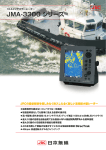
This equipment is a marine radar equipment consisting of a scanner unit and an integrated
color LCD display unit. The radar equipment consists of a scanner unit that generates
transmitting signals, transmits and receives radio waves, and amplifies receiving signals,
and a display system that displays radar images after removing unwanted radio wave
from the radar signals.
The radar equipment with which a magnetron tube is used as the transmitting tube
transmits 9.4 GHz (X band) pulse-modulated waves.
In addition to the basic radar functions, the radar equipment has functions for safe
navigation such as a radar trail display function, target tracking function, and AIS
information display function.
Field Service Manual
1
1-1
Chapter 1 Equipment Overview
1.2 Scanner Unit
1.2 Scanner Unit
The scanner unit is an antenna that transmits a radar signal into space, and sends the radar
signal reflected from a target into the equipment. The horizontal antenna beam width is
small for identifying the target bearing, and the scanner unit has a rotating mechanism for
detection in the entire surrounding area.
Some scanner units are provided for this equipment, and their usage is as follows:
ԘX band (4 kW) scanner unit: Compact and light weight
ԙX band (6 kW) scanner unit: Compact and light weight
ԚX band (10 kW) scanner unit: Compact and light weight
ԛX band (25 kW) scanner unit: High resolution, and high sensitivity
Figure 1.2-1 X-4 kW Scanner Unit
1-2
Chapter 1 Equipment Overview
1.2 Scanner Unit
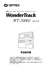
Figure 1.2-2 X-6 kW Scanner Unit
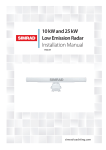
Figure 1.2-3 X-10 kW Scanner Unit
1
1-3
Field Service Manual
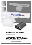
Figure 1.2-4 X-25 kW Scanner Unit
Chapter 1 Equipment Overview
1.3 Display Unit
1.3 Display Unit
The display unit processes a radar signal transmitted from the scanner unit, removes
unwanted radio wave, and plots/displays radar images in a specified observation range.
The user is to stand in front of the display unit and observe the conditions around the own
ship with the radar images displayed on the display unit by operating the cursor keys and
the MULTI control on the operation panel.
The display unit is shown below.
Figure 1.3-1 Display Unit (NCD-2182)
1-4
Chapter 1 Equipment Overview
1.4 Principal Functions
1.4 Principal Functions
This equipment has the following functions:
ԘSensitivity adjustment, and sea clutter and rain/snow clutter suppression
ԙInterference rejecter
ԚNavigation tools (cursor, VRM, EBL and parallel cursor)
ԛOwn track display
ԜRadar trail display
ԝTarget tracking
ԞAIS information display
ԟSelf-diagnostic function
Field Service Manual
1
1-5
Chapter 1 Equipment Overview
1.4 Principal Functions
1-6
Chapter 2 Equipment Configuration
2.1 Configuration
Chapter 2
Equipment Configuration
2.1 Configuration
2.1.1
Scanners and Transmitted Output Powers
Model number
Scanner
Transmitted
output power
Band
Rate of rotation
JMA-3314
620 mm Radome
4 kW
X
27 rpm
JMA-3316
3.9 FT SLOT ANTENNA
6 kW
X
27 rpm
JMA-3316HS
3.9 FT SLOT ANTENNA
6 kW
X
48 rpm
JMA-3334
620 mm Radome
4 kW
X
48 rpm
JMA-3336
3.9 FT SLOT ANTENNA
6 kW
X
27 rpm
JMA-3336HS
3.9 FT SLOT ANTENNA
6 kW
X
48 rpm
JMA-3340-4
4 FT SLOT ANTENNA
10 kW
X
27 rpm
JMA-3340-4HS
4 FT SLOT ANTENNA
10 kW
X
48 rpm
JMA-3340-6
6 FT SLOT ANTENNA
10 kW
X
27 rpm
JMA-3340-6HS
6 FT SLOT ANTENNA
10 kW
X
48 rpm
JMA-3355-7
7 FT SLOT ANTENNA
25 kW
X
24 rpm
JMA-3355-9
9 FT SLOT ANTENNA
25 kW
X
24 rpm
2
* Type of transmitted radio wave: P0N for all the models
Radar Configuration and Ship's Mains
Model number
Scanner
Display unit
Ship's mains
JMA-3314
NKE-2042
NCD-2182
12/24 VDC
JMA-3316
NKE-2062
NCD-2182
12/24 VDC
JMA-3316HS
NKE-2062HS
NCD-2182
24 VDC
JMA-3334
NKE-2042
NCD-2182
12/24 VDC
JMA-3336
NKE-2063
NCD-2182
12/24 VDC
JMA-3336HS
NKE-2063HS
NCD-2182
24 VDC
JMA-3340-4
NKE-2103-4
NCD-2182
24 VDC
JMA-3340-4HS
NKE-2103-4HS
NCD-2182
24 VDC
JMA-3340-6
NKE-2103-6
NCD-2182
24 VDC
JMA-3340-6HS
NKE-2103-6HS
NCD-2182
24 VDC
JMA-3355-7
NKE-2254-7
NCD-2182
24 VDC
JMA-3355-9
NKE-2254-9
NCD-2182
24 VDC
Field Service Manual
2.1.2
2-1
Chapter 2 Equipment Configuration
2.1 Configuration
Note:
A scanner unit and display unit are indicated on the nameplate of the equipment as
follows:
Scanner unitSCANNER UNIT
Display unitDISPLAY UNIT
2-2
Chapter 2 Equipment Configuration
2.2 Power System Diagram
2.2 Power System Diagram
Figure 2.2-1 JMA-3300 Power System Diagram
Field Service Manual
2
2-3
Chapter 2 Equipment Configuration
2.3 Functional System Diagram
2.3 Functional System Diagram
2.3.1
Scanner Unit
Figure 2.3-1 Functional System Diagram of Scanner Unit
NKE-2103 Scanner Unit
SLOT ANTENNA
ROTARY
JOINT
MOTOR
B101
ENCODER
㱂A,㱂B,㱂Z
FILTER
DIODE
LIMITER
MAG
V101
RECEIVER
PULSE
TRANS
Tune Control
DUMMY
LOAD
Receiver
Bandwidth
Control
SWITCHING
CIRCUIT
RF AMP
IF AMP
PC201
Tx Trigger/Pulse Width
VIDEO
AMP
MH
GENERATOR
POWER
SUPPLY
CIRCUIT
INTERFACE CIRCUIT
PC1101
AVR
PC1001
Status
Serial Com, BP, BZ, VD, TRIG
Rotation Control
DC+24V
DC+24V
Speed control
MOTOR CONTROL
POWER
PC1501
SAFETY SWITCH
DC+24V
S101
Figure 2.3-1 shows the functional system diagram of the scanner unit for this equipment.
When the power relay for the scanner unit in the display unit is turned on and power is supplied
to the scanner unit, the power circuit starts power supply to each circuit of the scanner unit. The
CPU in the interface circuit is started by starting the power supply, and preheating of the
magnetron is started after initialization. The scanner unit waits for a communication signal from
the display unit. A communication link is established when a communication signal is received,
and then the scanner unit is placed under control of the display unit.
2-4
Chapter 2 Equipment Configuration
2.3 Functional System Diagram
While the magnetron is being preheated, the interface circuit sets the operation of each
circuit of the scanner unit according to the initial setting value transmitted by the display
unit. After completion of preheating, the scanner unit informs the display unit that the
preheating is complete. When the operator performs operation to start transmission, a
transmission start command is sent through the communication line from the display unit,
and the scanner unit starts the scanner motor and the transmission.
A transmission timing pulse is generated in the interface circuit and input to the
modulator switching circuit. After high-voltage switching for the modulator, the
high-voltage pulse is further boosted by the pulse transformer and applied to the
magnetron for obtaining pulse-modulated microwave. The radar-signal pulse width and
repetition frequency are specified by a control command from the display unit.
The radar signal passes through the duplexer circuit configured with the circulator and the
rotary joint and transmitted into space from the antenna.
2
A signal reflected from a target is input through the antenna, and then input to the
receiving block by the duplexer function. After the received signal is amplified, it is
converted to IF frequency and log-detected, and turns into a radar video signal. If the
receiving tuning function is in automatic mode, the interface circuit processes the
received signal and automatically controls the tuning voltage to obtain optimum local
frequency.
The motor power circuit controlled by the interface circuit is turned on, DC power is
supplied to the motor driver circuit, and the motor starts running. The rotation control
signal output by the interface circuit is supplied to the motor driver circuit after
frequency-voltage conversion in the motor power circuit, by which the motor speed is
controlled. When the safety switch is turned off, power supply to the motor driver is
forcibly turned off, by which the motor is stopped. The radiation bearing of scanner beam
The received radar video signal, transmission timing signal, and antenna rotation signal
are sent to the display unit. The radar video signal is a non-processed, log-compressed
signal. The antenna rotation signal is an incremental signal, and 2048 rotation pulses and
reference bearing pulses per cycle are used.
When a specified time has passed during the stopping of the communication signal from
the display unit, the interface circuit moves into the protection mode, and forcibly stops
the transmission and the scanner unit.
2-5
Field Service Manual
is detected by the encoder.
Chapter 2 Equipment Configuration
2.3 Functional System Diagram
2.3.2
Display Unit
Figure 2.3-2 Functional System Diagram of Display Unit
Figure 2.3-2 shows the functional system diagram of the display unit for this equipment.
2-6
Chapter 2 Equipment Configuration
2.4 Input/Output Specifications
2.4 Input/Output Specifications
This section explains the signals to be connected to connectors in the I/F circuit
CMH-2235.
2.4.1
POWER (J1)
This is used for connection with the power supply.
PIN
NAME
DESCRIPTION
APPLICATION
1 1A
2 1A
3 1A
4
5 2A
6 2A
7 2A
SCANNER (J2)
This is used for connection with the scanner unit.
PIN
NAME
DESCRIPTION
APPLICATION
1 M2 M3 M+
4 M5 2A
6 GND
7 VDE
8 +12V
TXRX
9 1A
10 VD
11 MTR+
12 BZ
Field Service Manual
2.4.2
2
13 MTR14 TRGE
15 TRG
16 BP
2-7
Chapter 2 Equipment Configuration
2.4 Input/Output Specifications
2.4.3
GPS (J3)
This is used for connection with the GPS.
PIN
NAME
DESCRIPTION
1 +12V
Used for direct connection with a JRC GPS
receiver
2 GND
Same as above
3 GPSRX-
Data return
4 GPSRX+
Data input
5 GPSTX+
Used for direct connection with a JRC GPS
receiver
APPLICATION
GPS
6 NC
2.4.4
NMEA (J4)
This is used for connection with the AIS or external navigator.
*) If the AIS is connected, other NMEA equipment cannot be connected.
PIN
2.4.5
NAME
DESCRIPTION
APPLICATION
1 NAVTX+
Signal (+) transmitted to external equipment
2 NAV1TX-
Signal (-) transmitted to external equipment
3 NAVRX+
Signal (+) received from external equipment
4 NAV1RX-
Signal (-) received from external equipment
5 GND
GND
6 EVENT+
Dry contact input 1
Own ship's position mark
7 EVENT-
Dry contact input 2
Own ship's position mark
HDG (J5)
This is connected when a bearing signal is input to the radar.
PIN
2-8
NAME
DESCRIPTION
APPLICATION
1 NSKTX+
Signal (+) transmitted to the NSK
2 NSKTX-
Signal (-) transmitted to the NSK
3 NSKRX+
Signal (+) received from the NSK, GPS
compass, or another bearing sensor (NMEA)
4 NSKRX-
Same as above (-)
5 GND
Power GND for NSK
6 ALM+
Dry contact output 1
External-buzzer connection
7 ALM-
Dry contact output 2
External-buzzer connection
8 +5V
Power supply (+5 V) for the NSK
Chapter 2 Equipment Configuration
2.5 DIP-SW/Jumper Setting
2.5 DIP-SW/Jumper Setting
2.5.1
I/F Circuit CMH-2235
Jumper setting
A jumper post is installed at the location indicated in the figure below.
If an external buzzer is connected to the pin J5, use the jumper TB2 to determine whether
to open or close the buzzer contact in accordance with the status of use under normal
conditions.
Normally open contact when the pins 1-2 are jumpered (factory setting)
Normally closed contact when the pins 2-3 are jumpered
2
Field Service Manual
CMH-2235 TB2(1-2) short-circuit
2-9
Chapter 2 Equipment Configuration
2.5 DIP-SW/Jumper Setting
2.5.2
GYRO I/F Circuit CMJ-304E
DIP-SW/jumper setting
(1) TB100Not to be used. Leave the factory setting as is.
(2) TB105: Availability of setting if input voltage for the gyro is low
1-2: Ordinary setting (factory setting)
2-3: Setting when voltage for the gyro is low (CD56 is lighted when the voltage is
22 VDC or less. Even when the display system is turned off, the JMA-3300
operates receiving power from the display unit side. Thus, the switching of
TB105 setting is not necessary. (This switching does not cause any problem.))
Note:
z Use this setting only when voltage is low.
Do not use this with synchro setting.
Note that incorrect settings can lead to damage of the NSK unit.
(3) TB106 and TB107: Not installed
(4) TB108 and TB109: Not installed
(5) TB401-TB403: Availability of setting if input voltage for the gyro is low
1-2Ordinary operation
2-10
Chapter 2 Equipment Configuration
2.5 DIP-SW/Jumper Setting
(6) S4 and S5: Gyro setting and log setting
GYRO SIGNAL
S5 SETTING TABLE
STEP
ON
SYNC
OFF
2
3
360X
OFF OFF
180X
ON
OFF
90X
OFF
ON
36X
ON
ON
4
DIRECTION
NOR
OFF
DIRECTION
REV
ON
TYPE
LOG SIGNAL
1
5
6
PULSE
OFF
SYNC
ON
Don't care
PULSE/NM
7
8
OFF
800P㧛360X
OFF OFF
400P㧛180X
ON
OFF
200P㧛90X
OFF
ON
100P㧛30X
ON
ON
7
8
S4 SETTING TABLE
LOG ALARM
1
2
3
4
5
6
2
ON
OFF
ON
OFF
ON
LOG SIMULATOR
OFF
N.C.
GYRO ALARM TIME
HEADING SENSOR
SOURCE
NMEA BAUDRATE
SETTING
Don't care
any
5s
ON
0.5s
OFF
NMEA(HDT/THS)
ON
GYRO SIGNAL
OFF
4800
OFF OFF
9600
ON OFF
19200
OFF ON
38400
ON
ON
(7) S6: Reset switch
Resets the CPU.
(8) S7: Zero-degree setting switch
Sets, as the due north, the bearing at the point of pressing.
2-11
Field Service Manual
OTHER SETTING
GYRO SIMULATOR
Chapter 2 Equipment Configuration
2.5 DIP-SW/Jumper Setting
(9) S2 and S3: Selection of a gyro type
Left:Step
Right:Synchro
(10) S1: Gyro ON-OFF switch
Left:OFF
Right:ON
(11) S10: Other settings are not to be used. Set all to OFF.
LED
2.5.3
Processing Circuit CDC-1346BR
(1) S1: DIP-SW. All the bits are factory-set to OFF.
Do not change any of the factory settings.
1:OFF (Do not change this setting.)
2:OFF (Do not change this setting.)
3:OFF (Do not change this setting.)
4:OFF (Do not change this setting.)
5:OFF (Do not change this setting.)
6:OFF (Do not change this setting.)
2-12
Chapter 2 Equipment Configuration
2.5 DIP-SW/Jumper Setting
S1
2.5.4
T/R Control Circuit CMC-1205R
[Type of DIP switch]
2
y SW1, SW2
[Type of jumper pin]
y J92, J93, J95, J96
z NKE-2254 (2 units: 25 kW, X-band)
y Jumper pin setting
J92,J93,J95,J96: 1-2 jumpered
y DIP switch setting (: Switch)
SW2
3
4 5 6 7 8
1
2
Field Service Manual
ON
ON
1 2
SW1
2-13
Chapter 2 Equipment Configuration
2.5 DIP-SW/Jumper Setting
2-14
Chapter 3 Service Parts
3.1 Service Parts Lists for the Units
Chapter 3 Service Parts
3.1 Service Parts Lists for the Units
3.1.1
Included accessories
Table 3.1-1 7ZXRD0012 (JMA-3314)
Name/
Model
Parts
No.
Code
Fuse
F2
ST4-6.3AN1
5ZFCA00051
Fuse
F2
ST4-3.15AN1
5ZFCA00047
Shape (mm)
Quantity
Location
Application
I6.35
4
Inside processing Modulator
unit
For 12 VDC
I6.35
4
Inside processing Modulator
unit
For 24 VDC
31.8
31.8
Table 3.1-2 7ZXRD0012 (JMA-3334)
Name/Type Parts No.
Code
Shape (mm)
Quantity
Location
Application
3
Fuse
F2
ST4-6.3AN1
5ZFCA00051
Fuse
F2
ST4-3.15AN1
5ZFCA00047
I6.35
4
Inside processing Modulator
unit
For 12 VDC
4
Inside processing Modulator
unit
For 24 VDC
31.8
I6.35
Table 3.1-3 7ZXRD0013 (JMA-3316/HS)
Parts
No.
Fuse
F2
ST4-6.3AN1
Motor brush
54531-01
Shape (mm)
I6.35
5ZFCA00051
Quantity
I6.35
5ZFCA00047
I6.35
5ZFCA00050
4
Scanner Unit
NKE-2062
Inside processing Scanner Unit
unit
NKE-2062HS
Modulator
For 24 VDC
4
Scanner Unit
NKE-2062
Inside processing Scanner Unit
unit
NKE-2062HS
For Scanner Unit
motor
2
Scanner Unit
motor
31.8
–
BRXP05247
I8.0
32.0
Application
Scanner Unit
Inside processing NKE-2062
unit
Modulator
For 12 VDC
31.8
F3
Location
4
31.8
Fuse
F2
ST4-3.15AN1
Fuse
ST4-5AN1
Code
Field Service Manual
Name/
Model
3-1
Chapter 3 Replacement of Major Parts
3.1 Service Parts Lists for the Units
Table 3.1-4 7ZXRD0013 (JMA-3336/HS)
Name/Type Parts No.
Fuse
F2
ST4-6.3AN1
Shape (mm)
I6.35
5ZFCA00051
Quantity
I6.35
5ZFCA00047
I6.35
5ZFCA00050
4
Scanner Unit
NKE-2063
Inside processing Scanner Unit
unit
NKE-2063HS
Modulator
For 24 VDC
4
Scanner Unit
NKE-2063
Inside processing Scanner Unit
unit
NKE-2063HS
For Scanner Unit
motor
2
Scanner
31.8
Carbon brush
54531-01
–
8.0
BRXP05247
Application
4
31.8
F3
Location
Scanner Unit
Inside processing NKE-2063
Modulator
unit
For 12 VDC
31.8
Fuse
F2
ST4-3.15AN1
Fuse
ST4-5AN1
Code
For the scanner motor
32.0
Table 3.1-5 7ZXRD0026 (JMA-3340-4/4HS/6/6HS)
Name/
Model
Parts
No.
Fuse
ST4-5AN1
F2
Fuse
ST6-10AN1
F3
Code
Shape (mm)
5ZFCA00050
Quantity
Application
I6.35
4
Inside processing For Scanner Unit
unit
motor
I6.35
4
Inside processing For Scanner Unit
unit
power supply
31.8
5ZFCA00053
Location
31.8
Table 3.1-6 7ZXRD0015 (JMA-3355-7/9)
Name/
Model
Parts
No.
Fuse
ST6-10AN1
F2
Fuse
ST6-10AN1
F3
3-2
Code
Shape (mm)
I6.35
5ZFCA00053
Quantity
I6.35
31.8
Application
4
Inside processing Scanner Unit
unit
For motor
4
Inside processing For Scanner Unit
unit
power supply
31.8
5ZFCA00053
Location
Chapter 3 Service Parts
3.1 Service Parts Lists for the Units
3.1.2
Special parts
Table 3.1-7 NKE-2042 (JMA-3314)
Parts No.
Name
Type
Code
Manufacturer
Location
V201
Magnetron
MSF1421B
5VMAA00049
NJRC
Scanner Unit
A101
Circulator
FCX68
6AJRD00001
Toshiba
Scanner Unit
A102
Diode Limiter
NJS6930
5EZAA00024
NJRC
Scanner Unit
Table 3.1-8 NKE-2043 (JMA-3334)
Parts No.
Name
Type
Code
Manufacturer
Location
V101
Magnetron
MSF1421B
5VMAA00092
NJRC
Scanner
A101
Circulator
FCX68R
5AJIX00027
Orient
Microwave
Scanner
A102
Diode Limiter
NJS6930
5ATBT00006
NJRC
Scanner
Table 3.1-9 NKE-2062 (JMA-3316/HS)
Parts No.
Name
Type
Code
Manufacturer
Location
V101
Magnetron
MSF1422B
5VMAA00068
NJRC
Scanner Unit
A101
Circulator
FCX68
6AJRD00001
Toshiba
Scanner Unit
A102
Diode Limiter
NJS6930
5EZAA00024
NJRC
Scanner Unit
3
Table 3.1-10 NKE-2063 (JMA-3336)
Parts No.
Name
Type
Code
Manufacturer
Location
V101
Magnetron
MSF1422B
5VMAA00090
NJRC
Scanner
A101
Circulator
FCX68R
5AJIX00027
Orient
Microwave
Scanner
A102
Diode Limiter
NJS6930
5ATBT00006
NJRC
Scanner
Table 3.1-11 NKE-2103 (JMA-3340-4/4HS/6/6HS)
Name
Type
Code
Manufacturer
Location
V101
Magnetron
MAF1565N
5VHAA00102
NJRC
Scanner Unit
A101/A102
Circulator
FCX68R
5AJIX00027
Orient
Microwave
Scanner Unit
A103
Dummy
NJC4002
5ANDF00001
NJRC
Scanner Unit
A104
Filter
NJC9952
5AWAX00002
NJRC
Scanner Unit
A301
Diode Limiter
NJS6930
5ATBT00006
NJRC
Scanner Unit
Field Service Manual
Parts No.
3-3
Chapter 3 Replacement of Major Parts
3.1 Service Parts Lists for the Units
Table 3.1-12 NKE-2254 (JMA-3355-7/9)
Parts No.
Name
Type
Code
Manufacturer
Location
V1
Magnetron
M1568BS
5VMAA00106
NJRC
Scanner Unit
A101/A102
Circulator
NJC3901M
5AJBV00007
NJRC
Scanner Unit
A103
Dummy
NJC4002
5ANDF00001
NJRC
Scanner Unit
A104
Filter
NJC9952
5AWAX00002
NJRC
Scanner Unit
A301
Diode Limiter
NJS6930
5ATBT00006
NJRC
Scanner Unit
3.1.3
Repair Circuit Block
Table 3.1-13 NKE-2042 (JMA-3314)
Location
Circuit Block
Type
Scanner Unit
Motor Unit
7BDRD0023*
Scanner Unit
Modulation circuit
CME-322
Scanner Unit
Receiver
CAE-475
Remarks
"*" means revision, such as A, B and so on.
Table 3.1-14 NKE-2043 (JMA-3334)
Circuit Block
Motor Unit
Type
RoHS
Remarks
٤
7BDRD0052*
Compound Modulator
CME-385
Circuit
٤
Receiver
٤
NRG-239
Including CAE-548
"*" means revision, such as A, B and so on.
Table 3.1-15 NKE-2062 (JMA-3316/HS)
Location
Circuit Block
Type
Remarks
Scanner Unit
Motor with gear
CBP-169
DC brushless
Scanner Unit
Modulation circuit
CME-339
Excluding Magnetron
Scanner Unit
Receiver
NRG-226
Including CAE-475-1
Table 3.1-16 NKE-2063 (JMA-3336)
Circuit Block
Type
RoHS
CBP-218
٤
Compound Modulator
CME-386
Circuit
٤
Receiver
٤
Motor Unit
3-4
NRG-239
Remarks
Including CAE-548
Chapter 3 Service Parts
3.1 Service Parts Lists for the Units
Table 3.1-17 NKE-2103 (JMA-3340-4/4HS/6/6HS)
Location
Circuit Block
Type
Remarks
Scanner Unit
Motor with gear
7BDRD0048
DC brushless
Scanner Unit
Modulation circuit
CME-363
Excluding Magnetron
Scanner Unit
Receiver
NRG-610
Including CAE-529-1
Scanner Unit
Power supply circuit
CBD-1783
Scanner Unit
Encoder
CHT-71A
Scanner Unit
Motor control power circuit CBD-1779
Scanner Unit
Fan
7BFRD0002
Table 3.1-18 NKE-2254 (JMA-3355-7/9)
Location
Circuit Block
Type
Remarks
Scanner Unit
Motor with gear
7BDRD0044A*
DC brushless (ordinary speed)
Scanner Unit
Motor with gear
7BDRD0045A*
DC brushless (high speed)
Scanner Unit
Modulator
NMA-550
CPA-264 included
CMB-404 included
Excluding Magnetron
Scanner Unit
Receiver
NRG-162A
CMA-866A included
Scanner Unit
Modulation circuit
CPA-264
Scanner Unit
Power supply circuit
CBD-1682A
Scanner Unit
T/R control circuit
CMC-1205R
Scanner Unit
Motor control circuit
CBD-1779
Scanner Unit
Heater control circuit
CHG-216
Scanner Unit
Encoder
CHT71A
Scanner Unit
Fan
7BFRD0002*
3
Optional (100 VAC)
"*" means revision, such as A, B and so on.
Table 3.1-19 NCD-2182
Circuit Block
Type
Display Unit
Processing circuit
CDC-1346BR
Display Unit
I/F circuit
CMH-2235
Display Unit
I/F circuit
CQC-1262
Display Unit
Operation circuit
CCK-991
Display Unit
Operation circuit
CCK-1017
Display Unit
Fuse
MF60NR 250V 10
Remarks
Field Service Manual
Location
F1
3-5
Chapter 3 Replacement of Major Parts
3.2 Exploded Diagrams
3.2 Exploded Diagrams
3.2.1
NKE-2042
No.
Name
Product code
Service code
1
Upper Radome Assy.
MPBC36726
MPBC36726
2
Lower Radome Assy.
MPBX39791
MPBX39791
2-1
Lower Radome
MPBC36068A
2-2
Packing
MTT307991
2-3
Bolt
MPTG31164
2-4
Seal Washer
BRTG03190
2-5
O-Ring
BRPK00019
2-6
Cable Clamp
BRJD05037
2-7
Spacer
MTT307999
3
Chassis Assy.
MPBX39946
4
Main Shaft Assy.
MPGK30870A
4-1
Rotary Joint
MPAB02055
4-2
Housing
MTC301103
4-3
Connecting Wave Guide
MPAB31163
4-4
Bearing
BRGK05421
4-5
C-Ring
BRTG00735
4-6
Push Plate
MTB361576
4-7
Push Plate
MTB361502
4-8
Antenna Assy.
MPAE30095A
4-9
Spur Gear
MPGK02946
4-10
Motor Assy.
7BDRD00023
4-11
Reed Switch
5MPAB00001
4-12
NB4X10BS
BSNB04010B
4-13
NC3X12BS
BSNC03012B
4-14
NC4X8BS
BSNC04008B
3-6
Notes
6006ZZCM/1K
MPAE30095A
7BDRD00023
Chapter 3 Service Parts
3.2 Exploded Diagrams
5
Name
Product code
Service code
Notes
Transceiver Assy.
MDNZT5011A
NZT-12
5-1
Receiver Assy.
MDNRG5061
NRG-225
5-2
Modulator Assy.
MDMW10830
CME-322
5-3
Mounting Plate
MPBX39034
5-4
Modulator Assy. Cover
MTB360476A
5-5
Magnetron Cover
MTB360477B
5-6
Corner Wave Guide
MTM003700
5-7
Guide Plate
MTB358269
5-8
Screw
BRTG07161
5-9
Spacer
BRBP05094
5-10
Upset Bolt
BRTG06852
5-11
Circulator
5AJAA00004
FCX68
5-12
Diode Limiter
5EZAA00024
NJS6930
5-13
Magnetron
5VMAA00049
5-14
NB4X20BS
BSNB04020B
5-15
NA4X10BS
BSNA04010B
5-16
NC4X10BS
BSNC04010B
5-17
Filter
MPAB31167
6
Push Plate
MTB319525
7
NC4X10BS
BSNC04010B
8
NB4X10BS
BSNB04010B
5VMAA00049
MSF1421B
3
Field Service Manual
No.
3-7
Chapter 3 Replacement of Major Parts
3.2 Exploded Diagrams
Figure 3.2-1 Exploded Diagram of NKE-2042
3-8
Chapter 3 Service Parts
3.2 Exploded Diagrams
3.2.2
NKE-2043
NO.
PART NAME
PRODUCT CODE SERVICE CODE
NOTE
1
Upper Radome Assy.
MPBC36726A
2
Lower Radome Assy.
MPBX46698
2-1
Lower Radome
MPBC36068B
2-2
Packing
MTT307991
2-3
Bolt
MPTG31164
HEX5X40
2-4
Seal Washer
BRTG03190
SUS W-5
2-5
O-Ring
BRPK00019
P4 ID3.8 d1.9
2-6
Cable Gland
BRJD05113
2-7
Spacer
MTT307999
3
Base Plate Assy.
MPBX46699
4
Antenna Drive Assy.
MPGK31386
4-1
Antenna Assy.
MPAE30564
4-2
RJ Shaft Assy.
MPAB32149
4-3
Housing
MTC301909
4-4
Gear Assy.
MPGK02946
4-5
Waveguide
MTM302099
4-6
Bearing Push Plate
MTB400407
4-7
Push Plate
MTB399834
4-8
Bearing
BRGK05421
6006ZZCM/1K
4-9
Bolt
BRTG08900
M4X25 SW W
4-10
Bolt
BRTG06852
M4X12 SW W
4-11
C-Ring
BSSC30000S
SC30SK5M/T1.5
4-12
Proximity Switch Bracket
MTB399803
4-13
Proximity Switch
-
Motor Assy.
MPEM30230
5-1
Motor
7BDRD0052A
5-2
Motor Bracket
MTB400408
NRS-102-70F
7BDRD0052A
Field Service Manual
5
3
3-9
Chapter 3 Replacement of Major Parts
3.2 Exploded Diagrams
NO.
6
PART NAME
PRODUCT CODE SERVICE CODE
NOTE
Transceiver Assy.
MDNZT5030
6-1
Main Chassis
MPBX46700
6-2
Corner Waveguide
MTM302115
6-3
Receiver Unit
MDNRG5108
6-4
Filter
MPAB32161
6-5
Guide Plate
MTB400460
6-6
Circulator
5AJIX00027
5AJIX00027
FCR68R
6-7
Diode Limiter
5ATBT00006
5ATBT00006
NJS6930
6-8
Cross-recessed Head Screw
BRTG09936
M4X75FE
6-9
Bolt
BRTG09167
M4X12 SW
6-10
Compound Modulator Circuit MDMW11168
Unit
CME385
6-11
Magnetron
5VMAA00092
5VMAA00092
6-12
Cover
MTB400411
7
Push Plate
MTB319525
8
Bolt
BRTG06852
M4X12 SW W
9
Cable Clamp
BRBP05605
FGC-8-M4
10
O-Ring
BRPK05256
P12 ID=11.8 D=2.4
3-10
NZT2043
NRG239
MSF1421B
Chapter 3 Service Parts
3.2 Exploded Diagrams
Figure 3.2-2 Exploded Diagram of NKE-2043
3-11
Field Service Manual
3
Chapter 3 Replacement of Major Parts
3.2 Exploded Diagrams
3.2.3
NKE-2062
No.
Name
Product code
Service code
1
Radiator Assy.
MPAE30324
2
Antenna Support Assy.
MPGK30781
3
Upper Housing Assy.
MPBX38807A
3-1
Upper Housing
MTC301686A
3-2
Wave Prevention Ring
MTT307768
3-3
V-Ring
BRPK00189
Drive Assy.
MPGK30751
4-1
Main Shaft
MTC300209B
4-2
Key
MTL310809
4-3
Bearing
BRGK05420
4-4
Spacer
MTL303193
4-5
Spur Gear
MTG300325A
4-6
Magnet Support
MPBC33954
4-7
Spacer
MTL303194
4-8
Bracket
MTC300358B
4-9
Retaining Ring Type-C
BRTG05289
4-10
Bearing
BRGK05409
4-11
Mounting Plate
MTB383221
4-12
Bearing Nut
BRTG06929
4-13
Magnet
5MPAB00001
4-14
Reed Switch
5KRAA00058
5
Rotary Joint Assy.
MPAB30186
6
Motor Assy.
MPGK30750
6-1
Motor
H-7BDRD0041
6-2
Brush
-
Transceiver Assy.
MDNZT5028
7-1
Magnetron
5VMAA00049
5VMAA00049
MSF1421B
7-2
Modulator Assy.
MDMW10829
CME-323
CME-323
7-3
Receiver Assy.
MDNRG5060
NRG-226
NRG-226
7-4
Circulator
5AJAA00004
FCX68
7-5
Diode Limiter
5EZAA00024
NJS6930
7-6
Chassis Assy.
MPBX38805
7-7
Cover
MPBC36158
4
7
3-12
NAX-43-4
Notes
NAX-43-4
6011ZZ
6009ZZ
AN09
CBP-153
CBP-153
BRXP05247
NZT-2062
Chapter 3 Service Parts
3.2 Exploded Diagrams
No.
8
Name
Product code
Connecting Wave Guide
MPAB31161
8-1
Choke Flange
MTM300624B
8-2
Connecting Wave Guide
MTM301492A
8-3
Push Plate
MTB361809
9
Packing
MTT305919A
10
Lower Housing Assy.
MPBX38806A
10-1
Lower Housing
MTC301687
10-2
Switch Cover
MPPK00925A
10-3
Switch
5SAAJ00029
12
Washer
MTL315466
13
Spring Washer
BRTG00404
14
Hexagonal Nut
BRTG05643
15
Coated Bolt
BRTG06849
16
Seal Washer
BRTG06850
17
Screw
MTL006545A
18
Spring Washer
BRTG00747
19
Washer
BRTG00224
20
O-Ring
BRPK00027
21
Hexagonal Bolt
BRTG06851
24
Spring Washer
BSSW06000S
25
Hexagonal Bolt
BRTG05418
26
Stay
MPDM00675A
27
Shaft
MTL314603
28
Gasket
MTT308695
29
Clamp Gland
MPTG30399
30
Washer
BRTG00883
31
Ground Cable
MPKC06160
Service code
Notes
3
22
Field Service Manual
23
3-13
Chapter 3 Replacement of Major Parts
3.2 Exploded Diagrams
Figure 3.2-3 Exploded Diagram of NKE-2062
3-14
Chapter 3 Service Parts
3.2 Exploded Diagrams
NKE-2063
NO.
PART NAME
PRODUCT CODE SERVICE CODE
1
Radiator Assy.
MPAE30324A
2
Drive Assy.
MPGK31394
2-1
Upper Housing
MTC301913
2-2
V-Ring
BRPK00189
2-3
Bearing
BRGK05625
2-4
Retaining Ring Type-C
BRTG09940
2-5
Antenna Support
MTC301915
2-6
Seat
MTT314164
2-7
Slide Plate
MTT308077
2-8
O-Ring
BRPK00054
2-9
Spacer
MTL329303
2-10
Key
MTL329304
2-11
Gear
MTG300541
2-12
Bearing Nut
BRTG06929
2-13
Magnet Assy.
MPBC45971
2-14
Bracket
MTC301916
2-15
Bolt
BRTG09297
2-16
Waveguide
MTM302099
2-17
Push Plate
MTB399834
2-18
Bolt
BRTG08900
2-19
Rotary Joint
MPAB32153
Motor Assy.
MDBW10896
CBP218
3-1
Motor
7BDRD0041A
7BDRD0041A
3-2
Chassis
MTB399835
3-3
Cover
MTB399836
3-4
Slit Plate
MTB124251
3-5
Spacer
BRBP06320
3-6
Photointerrupter
3-7
Brush
BRXP05247
Proximity Switch Assy.
MPSW30190
4-1
Proximity Switch Bracket
MTB399837
4-2
Proximity Switch
3
4
-
-
NAX-43-4Y
NOTE
NAX-43-4Y
6010ZZCM/5K
P42
3
M8X25 SW W
M4X25 SW W
CBP-218
BSB-318E
OJ-431-30
54531-01
Field Service Manual
3.2.4
NRS-102-70F
3-15
Chapter 3 Replacement of Major Parts
3.2 Exploded Diagrams
NO.
5
PART NAME
PRODUCT CODE SERVICE CODE
NOTE
Lower Housing Assy.
MPBX46703
5-1
Lower Housing
MTC301914
5-2
Seat
MTT314165
5-3
Switch Cover
MPPK00925A
5-4
Packing
MTT305919A
5-5
Breathing Cap
MTV302550
5-6
Cable Gland
BRJD05113
5-7
Packing
MTV304950
6
Stay
MPDM00675A
7
Push Plate
MTB399907
8
Transceiver Assy.
MDNZT5031
8-1
Main Chassis
MPBC45972
8-2
Circulator
5AJIX00027
5AJIX00027
FCX68R
8-3
Diord Limiter
5ATBT00006
5ATBT00006
NJS6930
8-4
-
FGA26-16B
NZT2063
-
8-5
Receiver Unit
MDNRG5108
8-6
CIR-Bracket1
MTB400635
8-7
CIR-Bracket2
MTB400636
8-8
Filter
MPAB32161
8-9
Guide Plate
MTB400460
8-10
MG-PIN
MTL325492
8-11
Bolt
BRTG09167
8-12
Compound Modulator Circuit MDMW11169A
Unit
CME386
8-13
Magnetron
5VMAA00090
5VMAA00090
8-14
Cover Assy.
MPBC46094
8-15
Support Plate
MTB400681
8-16
Cable Clamp
BRBP05605
9
Bolt
MPTG32219
10
Spring Washer
BRTG00747
M8
11
Washer
BRTG00224
M8
12
Sealing Washer
BRTG06850
SUSW8S1
13
O-Ring
BRPK00027
P7
14
Bolt
BRTG09004
M5X16 SW W
15
Cap Screw
BRTG09939
M8X25AL
16
Bolt
BRTG09937
M6X45
17
Spring Washer
BSSW06000S
M6
18
Connector Assy.
MPBC46111
19
Brass Washer
MTL325583
3-16
NRG239
M4X12 SW
MSF1422B
Chapter 3 Service Parts
3.2 Exploded Diagrams
PART NAME
PRODUCT CODE SERVICE CODE
NOTE
20
Spring Washer
BRTG00404
M10
21
Nut
BRTG05643
M10
22
Push Plate
MTB400735
3
Field Service Manual
NO.
3-17
Chapter 3 Replacement of Major Parts
3.2 Exploded Diagrams
Figure 3.2-4 Exploded Diagram of NKE-2063
3-18
Chapter 3 Service Parts
3.2 Exploded Diagrams
NKE-2103
No.
1
Name
Product code
Service code
Radiator Assy.
MDNAX5041
1-1
Radiator Assy.
MDNAX5041
1-2
Hexagonal Bolt
BRTG07249
M10X35SUS S Coat
1-3
Spring Washer
BRTG00404
SW10 SUS
1-4
Washer
MTL315466
Antenna Support Assy.
MPGK31182
2-1
Antenna Support
MTC301684
2-2
Slide Plate
MTT309252
2-3
Waterproof Ring
MTT309256A
2-4
O-Ring
BRPK00054
Upper Housing Assy.
MPBX44085
3-1
Upper Housing
MTC301682
3-2
V-Ring
BRPK00189
V-100A
3-3
Cable Clamp
BRBP06738
OA-W1611EC1-BB
Main Shaft Assy.
MPGK31181
4-1
Main Shaft
MTC301685
4-2
Spur Gear
MTG300511
Large
4-3
Spur Gear
MTG300424A
Small
4-4
Bracket
MTC301655
4-5
Key
MTL325003
4-6
Spacer 1
MTL325004
4-7
Spacer 2
MTL325005
4-8
Bearing
BRGK05420
6011ZZ
4-9
Bearing
BRGK05409
6009ZZ
4-10
Retaining Ring Type-C
BRTG05289
HC75 SK5
4-11
Bearing Nut
BRTG06929
AN09
4-12
C Sems Screw
BSNC03010B
NC3X8Bs
5
Rotary Joint Assy.
MPAB31563
6
DC Motor with Reduction
Gear
H-7BDRD00048
7
Connecting Wave Guide
Assy.
MPAB31564
7-1
Connecting Wave Guide
MTM301722A
7-2
Choke Flange
MTM301843
7-3
Connecting Guide Push Plate MTB366792A
7-4
Hexagonal Bolt
2
3
4
BRTG08900
NAX-16B-6
Notes
NAX-16B-6
P42
7BDRD00048
3
CBP-202
Upset with M4X25 SUS SW W
3-19
Field Service Manual
3.2.5
Chapter 3 Replacement of Major Parts
3.2 Exploded Diagrams
No.
8
Name
Product code
Service code
Notes
Encoder Assy.
MPEM30205
8-1
BP Generation Circuit
MDMW11070
8-2
Spur Gear
MTT006909B
8-3
Turn-Stopper
MTD001842
Lower Housing Assy.
MPBX44086A
9-1
Lower Housing
MTC301683
9-2
Packing
MTT312329
9-3
Breathing Cap
MTV302550
9-4
Packing
MTT305919A
9-5
Switch Cover
MPPK00925A
9-6
Cable Push Plate
MTB366112
9-7
Nylon Clamp
BRBP00009
9-8
Screw
BSNK04010B
NK4X10Bs
9-9
V Sems Screw
BSNC04010B
NC4X10Bs
9-10
B Sems Screw
BSNB05010B
NB5X10Bs
Tranceiver Assy.
MDNZT5023
NZT-2103
10-1
Main Chassis
MPBX44420
10-2
Wave Guide Circuit
MPAB31606
10-2-1
CIR-Attachment
MTB389799
10-2-2
Receiver Unit
MDNRG5093
10-2-3
Diode Limiter
5ATBT00006
NJS6930
10-2-4
Circulator
5AJIX00027
FCX68R
10-2-5
Filter
5AWAX00002
NJC-9952
10-2-6
Guide Plate
MTL326122
10-2-7
Dummy Load
5ANDF00001
10-2-8
Spacer
MTL318403
10-2-9
MG-PIN
MTL325492
9
10
10-2-10
CHT-71A
NRG-610
CHT-71A
NRG-610
NJC4002
-
10-2-11 Hexagonal Bolt
BRTG07397
Upset with M4X12 SW
SUS304
10-2-12 Screw
BRTG07156
M4X70 Bs
10-2-13 C Sems Screw
BSNC04010B
NC4X10Bs
10-2-14 Spring Washer
BSSW04000S
SW4
10-2-15 Washer
BSFW04000B
W4Bs
10-3
Modulator Assy.
MPBX44290
CME-363
CME-363
10-4
Power Supply Assy.
MPBX44291
CBD-1783
CBD-1783
10-5
Motor Control Power Circuit
MDBW10832
CBD-1779
CBD-1779
10-6
Magnetron
5VMAA00102
5VMAA00102
MAF1565N
10-7
Brake Resistor
-
CFA-252
10-8
Filter Circuit
-
CFR-234
10-9
Cover
MTB389805
10-10
Nut Plate
MTB388518
10-11
Connection Plate
MTB388903
3-20
Chapter 3 Service Parts
3.2 Exploded Diagrams
No.
Name
Product code
Service code
Notes
10-12
Motor Cover
MTB391765
10-13
B Sems Screw
BSNB04012B
NB4X12Bs
10-14
C Sems Screw
BSNC04010B
NC4X10Bs
10-15
C Sems Screw
BSNC04016B
NC4X16Bs
10-16
C Sems Screw
BSNC03008B
NC3X8Bs
11
Encoder Plate
MTB388510A
12
Stay
MPDM30321
13
Ground Cable
H-7ZCRD1504
14
Shaft
MTL325006
15
Screw
MTL006545A
M8X35 Machining
16
Spring Washer
BRTG00747
SW8 SUS
17
Washer
BRTG00224
W8
18
O-Ring
BRPK00027
P7
19
Clamp Gland
MPTG30399
20
Cover
BRTG01414
21
Gasket
MTT308695A
22
Washer
BRTG00883
23
-
24
-
3
Coated Hexagonal Bolt
BRTG09192
M8X20 SUS304 coated
26
Seal Washer
BRTG06850
SUSW8S1
27
Hex-Head Setscrew
BRTG1030G
M4X0.7X6 SUS304
28
Hexagonal Bolt
BRTG09297
M8X25 FE SW W ZMC4RBU
29
Upset Bolt
BRTG09296
M6X70 FE SW W ZMC4RBU
30
C Sems Screw
BSNC04025B
NC4X25Bs
31
Upset Bolt
BRTG06852
M4X12 SW W SUS304
32
Upset Bolt
BRTG09004
M5X16 SW W SUS304
33
B Sems Screw
BSNB05010B
NB5X10Bs
34
B Sems Screw
BSNB04012B
NB4X12Bs
35
C Sems Screw
BSNC04010B
NC4X10Bs
36
C Sems Screw
BSNC03008B
NC3X8Bs
Field Service Manual
25
3-21
Chapter 3 Replacement of Major Parts
3.2 Exploded Diagrams
Figure 3.2-5 Exploded Diagram of NKE-2103
3-22
Chapter 3 Service Parts
3.2 Exploded Diagrams
3.2.6
NKE-2254
No.
Name
1
Product code
Radiator Assy.
Service code
NAX-16B
Notes
274.32
cm/213.36
cm/182.88 cm
1-1
Hexagonal Bolt
BRTG07249
HEX10X35 SUS304
1-2
Spring Washer
BRTG00404
SW10
1-3
Washer
MTL315466
Antenna Support Assy.
MPBX40223
2-1
Antenna Support
MTC301223A
2-2
Slide Plate
MTT309252
2-3
O-Ring
BRPK00054
2
3
P42 ID41.7 D3.5 Type 1A
Housing Assy.
3-1
Housing
MTC301727
3-2
Bearing Sleeve
MTL317432
3-3
Breathing Cap
MTT309253
3-4
Upset Bolt
BRTG09305
M5X12 FF ZMC4RBU
3-5
Safety SW
MDLW11931
CSD-654
3-6
Switch Cover
MPPK00925A
3-7
Cover (large)
MTB389969
3-8
Cover (small)
MTB389970
3-9
NK5X10Bs
BSNK05010B
3-10
NK5X12Bs
BSNK05012B
Cover Assy.
MPBX44875
4-1
Cover
MTC301729
4-2
Cover Packing
MTV303883
4-3
Hexagonal Bolt
MPTG31381
4-5
Spring Washer
BRTG00747
M8SUS3042 3.2X2
4-4
Washer
BRTG00224
M8SUS304 round
polished type 1
4-6
Seal Washer
BRTG01826
M8 SUS
Field Service Manual
4
3
3-23
Chapter 3 Replacement of Major Parts
3.2 Exploded Diagrams
No.
5
Name
Product code
Service code
Notes
Main Shaft Assy.
MPGK30895C
5-1
Flange
MTC301224A
5-2
Main Shaft
MTH300568A
5-3
Spur Gear
MTG300423A
5-4
Spur Gear
MTG300424
5-5
Bearing Push Plate
MTB366794A
5-6
Key
MTL317433
5-7
Radial Ball Bearing
BRGK05410
6012ZZ CM/5K
5-8
Radial Ball Bearing
BRGK05409
6009ZZ CM/5K
5-9
C-Ring
BRTG06164
5-10
Bearing Washer
BRTG07261
AW10X ID50
5-11
O-Ring
BRPK05043
G155 Type 1 A
5-12
AN10
BSAN10000S
AN10 M50X1.5
6
V-Ring
BRPK00189
V-100A
7
Hexagonal Bolt
BRTG07268
M8X25 TI
8
Spring Washer
BRTG07270
M8 TI
9
Washer
BRTG07267
M8 TI
10
Coated Hexagonal Bolt
BRTG06849
M8X23 Coated
2471L=15 SUS304
11
Rotary Joint Assy.
MPAB31188
12
Connecting Wave Guide
Assy.
MPAB31207A
13
Encoder Assy.
MPEM30202
13-1
BP Generation Circuit
MDMW11068
13-2
Spur Gear
MTT006909B
13-3
Turn-Stopper
MTD001842
13-4
Encoder Plate
MTB366793A
13-5
Upset Bolt
BRTG06852
14
Motor Assy.
14-1
M4X12 SW W SUS304
MPEM30204
-
MPEM30204
CBP-168A
-
14-3
Motor Flange
MTC301225
14-4
Hexagonal Bolt
BRTG09307
M8X30 SW W SUS304
14-5
Hexagonal Bolt
BRTG09306
M8X20 SW W FE ZMC
Gland (A30)
MPJD30062A
15-1
Clamp Gland
MPTG31572A
15-2
Gasket
BRPK00108
15-3
Washer
BRTG01246
30B AL
15-4
Cover
BRTG01415
30 AL
15
3-24
CHT-71A
-
Motor
14-2
CHT-71A
Chapter 3 Service Parts
3.2 Exploded Diagrams
16
Name
Product code
Service code
Notes
Gland (A25)
MPJD30063A
16-1
Clamp Gland
MPTG31573A
16-2
Gasket
BRPK00134
A25a
16-3
Washer
BRTG00883
25A AL
16-4
Cover
BRTG01414
25 AL
17
Heat Radiation Board Assy.
MPBC43035
18
Power Supply Unit
MPBX44439
18-1
Chassis Assy. (PS)
MPBX44440
18-2
Power Supply Circuit
MDBW10837
19
-
-
20
Motor Control Assy.
MPBX44318A
CBD-1682A
20-1
Motor Control Chassis Assy. MPBX44319
20-2
Motor Control Power Circuit MDBW10832
CBD-1779
Tranceiver Assy.
MDNZT5024A
NZT-1125
21-1
Modulator Assy.
MDNMA5077A
NMA-550
21-2
Main Chassis Assy.
MPBX44445
21-3
Cover Assy. (L)
MPBX44446
21-4
Cover Assy. (S)
MPBX44447
21-5
Modulation Circuit
MDLW11930
21-6
Magnetron
-
21-7
Pulse Transformer
-
21-8
Flame
MPBC43040
21-9
Holding Plate
MTB389330
21
21-10 Circulator
-
21-11 Diode Limiter
-
21-12 Connecting Wave Guide
MPAB31622
21-13 Guide Plate
MTC301794
21-14 Spacer
MTL318403
3
CPA-264
(MDLW11927)
CPA-264
5VMAA00106
21-15 Spurious Filter
-
NJC9952
21-16 Dummy Load Assy.
-
NJC4002
21-17 TR CONT PC plate
-
21-18 Receiver
MDNRG5094A
21-19 Nut Plate
MTB389894
21-20 Fan
MPEM30151
21-21 NC4X30Bs
BSNC04030B
21-22 Hexagonal Bolt
BRTG07502
21-23 O-Ring
BRPK00019
CMC-1205R
CMC-1205R
NRG-162A
NRG-162A
Upset with M5X16 SW W
SUS304
3-25
Field Service Manual
No.
Chapter 3 Replacement of Major Parts
3.2 Exploded Diagrams
No.
Name
Product code
Notes
21-24 Hexagonal Bolt
BRTG07397
Upset with M4X12 SW
SUS304
21-25 Screw
BRTG05659
NK4X0.7X65Bs
22
Performance Monitor
23
Performance Monitor
Adapter
MPBC43041A
24
Heater kit
MDMW11067A
-
24-1
Heater
-
24-2
Plate Clamp 1
MTB374149
24-3
Plate Clamp 2
MTB374150
24-4
Heater Terminal Board Assy. MPTE30386
25
NC4X10Bs
BSNC04010B
26
NC4X16Bs
BSNC04016B
3-26
Service code
NJU-85
NJU-85
(CHG-216P)
Chapter 3 Service Parts
3.2 Exploded Diagrams
Figure 3.2-6 Exploded Diagram of NKE-2254
3-27
Field Service Manual
3
Chapter 3 Replacement of Major Parts
3.2 Exploded Diagrams
3.2.7
NCD-2182
No.
Name
Code
1
LCD
MPXP34814
2
Cover
MTV302382
3
USB Cover
MTT313751
4
Spacer
BRBP05062
5
I/F circuit
CQC-1262
6
Tapping screws
BRTG09751
7
Bezel Packing
MTV304868
8
Soft key
MTV304865A
9
Operation Circuit
CCK-1017
10
Main Operation Rubber
MTV304885
11
Operation Circuit
CCK-991
12
I16 Knob
MPHD30383
13
I30 Knob
MPHD30380
14
PT Screw
BRTG09223
15
LCD Push Plate
MTB397474A
16
PT Screw
BRTG09224
17
Processing Circuit
CDC-1346BR
18
Embedded Screw
BSNC03006B
19
Locking Card Spacer
BRBP00564
20
Locking Card Spacer
BRBP07253
21
I/F Circuit CMH-2235
MDYW12732
22
Rear Cover
MTC301867
23
Screw
BSNK04025B
24
Rubber Washer
MTT311607
25
Washer
BSFW04000B
26
Spring Washer
BSSW04000S
27
Hexagonal Nut
BSHN04000W
28
Lock Nut
BSLN04000W
29
Butterfly Nut
BSBN04000B
30
Embedded Screw
BRTG03553
31
Embedded Screw
BRTG03547
32
Connector Nut
33
Rear Cover
MTB397333
34
Rubber Washer
MTT304158A
35
Tap-tight Binding screw
BRTG06198
36
Rubber Spacer
MTT313905
37
Rubber cushion
MTV304883
3-28
㧙
Notes
Chapter 3 Service Parts
3.2 Exploded Diagrams
No.
Name
Code
38
Knob Bolt
BRTG09876
39
Stand 3300
MTB397951
40
Screw Cover
MPNN46906
41
PL Nameplate
MPNN34331A
42
Environment label (10) Small
MPNN44289
43
Nameplate
MPNN46847
Notes
Figure 3.2-7 Exploded Diagram of NCD-2182
3
Field Service Manual
3-29
Chapter 3 Replacement of Major Parts
3.2 Exploded Diagrams
3-30
Chapter 4 Replacement of Major Parts
4.1 Precautions for replacing parts in the scanner unit
Chapter 4
Replacement of Major Parts
4.1 Precautions for replacing parts in the scanner
unit
Follow the precautions below to carry out parts replacement without getting injured.
Note:
z Confirm that all the radar equipment (if more than one unit is used) is turned off
before you start the parts replacement. For the sake of safety, turn off the main
power circuit breaker.
z Wear gloves to protect your hands during parts replacement. Be very careful not
to drop a tool or part when you work in high places.
z Carry out parts replacement while the ship does not roll or pitch much in a bay if
possible.
4
z Be careful that the radiator does not hit anyone during parts replacement. The
Field Service Manual
radiator can turn with wind or the like.
4-1
Chapter 4 Replacement of Major Parts
4.2 Parts Replacement for the Scanner Unit NKE-2042 (JMA-3314)
4.2 Parts Replacement for the Scanner Unit
NKE-2042 (JMA-3314)
[Required tools]
y Tools for removing the cover from the scanner unit
A wrench (width across flats 8 mm for M5 bolts)
y Tools used in each part replacement procedure
[Replacement procedure]
1 Loosen the six hexagon bolts, and then remove the radome.
2 Replace the parts, which need replacement, according to the procedures in
the subsequent sections.
Be careful not to lose screws or brackets removed during replacement.
4-2
Chapter 4 Replacement of Major Parts
4.2 Parts Replacement for the Scanner Unit NKE-2042 (JMA-3314)
3 After replacing the parts, align the triangle mark () and close the radome.
(Be sure to attach the cap when replacing the magnetron or the modulation circuit.)
Note:
When closing the radome, be sure the packing does not stick out, and close the radome
while avoiding dust and dirt.
4 Turn on the radar, and perform operation checks.
4.2.1
Magnetron MSF1421B
[Required tools]
y A Phillips screwdriver for M4 screws
y A Phillips screwdriver for M5 screws
y Shielded screwdriver
4
y Tools for removing the scanner unit covers (See Section 4.2)
[Replacement procedure]
1 Open the radome (See Section 4.2), and disconnect the 11 cables from the
Field Service Manual
transmitter-receiver unit.
4-3
Chapter 4 Replacement of Major Parts
4.2 Parts Replacement for the Scanner Unit NKE-2042 (JMA-3314)
Cables to be disconnected
Modulation Circuit CME-322
J1, J3, J4, J5, J14, J17, J201, J202
Receiver Circuit CAE-475
J2, J301, J302
2 Remove the seven screws (M4) and remove the transmitter-receiver.
The transmitter-receiver unit can be removed by sliding it.
3 Remove the four screws (M4) and remove the modulation circuit cover.
4-4
Chapter 4 Replacement of Major Parts
4.2 Parts Replacement for the Scanner Unit NKE-2042 (JMA-3314)
4 Remove the four screws (M4) and remove the magnetron cover.
5 Remove the lead wires (yellow and green) soldered to the pulse transformer,
4
remove the four screws (M4) holding the magnetron, then replace the
Field Service Manual
magnetron.
4-5
Chapter 4 Replacement of Major Parts
4.2 Parts Replacement for the Scanner Unit NKE-2042 (JMA-3314)
Note:
Use a shielded screw driver for magnetron replacement.
Touching the magnetron with metal (a tool) causes performance deterioration.
6 Solder the cable after cutting the leads (yellow and green) for the replacement
magnetron to an appropriate length.
After the magnetron replacement, carry out the work in reverse order of removal.
Be sure to tighten all the bolts and screws and connect all the cables.
Note:
y When soldering the lead of the magnetron, refer to the diagram above.
Make sure of the mounting position of yellow and green lead wires.
y Be careful that the lead wires (yellow and green) of the magnetron do not touch other
parts or the chassis.
Bringing the lead wires into contact with them can cause the discharge.
4-6
Chapter 4 Replacement of Major Parts
4.2 Parts Replacement for the Scanner Unit NKE-2042 (JMA-3314)
[Operation check]
After replacement, perform the following operations.
1 Turn on the radar, and maintain it in the standby state for 20 to 30 minutes.
2 Start transmission in a short pulse range, and gradually change to longer
ranges. At this time, open the service engineer menu and perform provisional
tuning adjustment.
If operation becomes unstable in the meantime, immediately change the equipment
back into the standby state, leave it there for 5 to 10 minutes, and restart transmission.
3 After long range transmission for about 15 minutes, open the service engineer
menu again and perform tuning adjustment.
In the service engineer menu, perform adjustment for the tune indicator bar on the
display to reach 80%.
4.2.2
Motor H-7BDRD0023
[Required tools]
y A Phillips screwdriver for M4 screws
y A Phillips screwdriver for M5 screws
4
y A wrench (width across flats 10mm for M6 bolts)
Field Service Manual
y Tools for removing the scanner unit radome (See Section 4.2)
4-7
Chapter 4 Replacement of Major Parts
4.2 Parts Replacement for the Scanner Unit NKE-2042 (JMA-3314)
[Replacement procedure]
1 Open the radome (See Section 4.2), and disconnect the motor cable from the
transmitter-receiver unit.
Cables to be disconnected
Modulation Circuit CME-322
J17
4-8
Chapter 4 Replacement of Major Parts
4.2 Parts Replacement for the Scanner Unit NKE-2042 (JMA-3314)
2 Remove the four screws (M4) and remove the motor.
After the motor replacement, carry out the work in reverse order of removal.
Be sure to tighten all the bolts and screws and connect all the cables.
4
[Operation check]
After replacement, perform the following operations.
1 Turn on the radar, transmit radar signals when the countdown is finished, and
check that radar images are displayed normally.
When starting the motor rotation, check if no abnormal noise will be emitted when it
is running, or when it stops.
4.2.3
Modulation Circuit CME-363
[Required tools]
Field Service Manual
y A Phillips screwdriver for M4 screws
y A Phillips screwdriver for M5 screws
y Tools for removing the scanner unit covers (See Section 4.2)
4-9
Chapter 4 Replacement of Major Parts
4.2 Parts Replacement for the Scanner Unit NKE-2042 (JMA-3314)
[Replacement procedure]
1 Refer to step 1 in Section 4.2.1 to disconnect the 11 cables from the
transmitter-receiver unit.
2 Refer to step 2 in Section 4.2.1 to remove the transmitter-receiver.
3 Remove the four screws (M4) and remove the modulation circuit cover.
4 Remove the magnetron lead wires (yellow and green) soldered to the pulse
transformer (H-7LPRD116).
4-10
Chapter 4 Replacement of Major Parts
4.2 Parts Replacement for the Scanner Unit NKE-2042 (JMA-3314)
5 Remove the nine screws (M4) that secure the modulation circuit, and replace
the modulation circuit.
If the heat radiation plate of the modulator is used, mount the insulating sheet straight
between TR1/TR13 and the heat radiation plate.
6
After the modulation circuit replacement, carry out the work in reverse order of
removal.
Be sure to tighten all the bolts and screws and connect all the cables.
4
Note:
y When soldering the lead of the magnetron, refer to the diagram above.
Make sure of the mounting position of yellow and green lead wires.
y Be careful that the lead wires (yellow and green) of the magnetron do not touch other
parts or the chassis.
Bringing the lead wires into contact with them can cause the discharge.
[Operation check]
After replacement, perform the following operations.
1 Turn on the radar, transmit radar signals when the countdown is finished, and
After long range transmission, open the service engineer menu, and confirm that the
magnetron current indicator shows 50 to 70%.
4-11
Field Service Manual
check that radar images are displayed normally.
Chapter 4 Replacement of Major Parts
4.2 Parts Replacement for the Scanner Unit NKE-2042 (JMA-3314)
4.2.4
Receiver NRG-225
[Required tools]
y A Phillips screwdriver for M4 screws
y A Phillips screwdriver for M5 screws
y A wrench (width across flats 7 mm for M4 bolts)
y Tools for removing the scanner unit covers (See Section 4.2)
[Replacement procedure]
1 Refer to step 1 in Section 4.2.1 to disconnect the 11 cables from the
transmitter-receiver unit.
2 Refer to step 2 in Section 4.2.1 to remove the transmitter-receiver.
3 Remove the 3D circuit and receiver from the transmitter-receiver unit
according to the procedure below.
a) Remove the two M4 screws near the magnetron.
4-12
Chapter 4 Replacement of Major Parts
4.2 Parts Replacement for the Scanner Unit NKE-2042 (JMA-3314)
b) Use a wrench to remove the four screws (M4) that secure the receiver, and replace
it.
c) After the receiver replacement, carry out the work in reverse order of removal.
Be sure to tighten all the bolts and screws and connect all the cables.
4
Note:
After receiver replacement, perform the assembly procedure, paying attention to the fitting of
the transmitter-receiver unit.
If the fitting is poor, remove the screws and perform the adjustment again.
[Operation check]
After replacement, perform the following operations.
1 Turn on the radar, transmit radar signals when the countdown is finished, and
check that radar images are displayed normally. Transmit radar signals on a
the adjustment in the service engineer menu until the tuning display bar on the
display unit reaches the eighth calibration mark.
4-13
Field Service Manual
long range and open the service engineer menu to adjust the tuning. Perform
Chapter 4 Replacement of Major Parts
4.3 Parts Replacement for the Scanner Unit NKE-2043 (JMA-3334)
4.3 Parts Replacement for the Scanner Unit
NKE-2043 (JMA-3334)
[Required tools]
y Tools for removing the cover from the scanner unit
A wrench (width across flats 8 mm for M5 bolts)
y Tools used in each part replacement procedure
[Replacement procedure]
5 Remove the radome.
The radome is fixed with 6 hexagonal bolts.
The figure below shows the positions for 6 bolts.
Bottom view
Note:
Place the removed radome in a safe place.
Be sure not to be blown off by the wind.
4-14
Chapter 4 Replacement of Major Parts
4.3 Parts Replacement for the Scanner Unit NKE-2043 (JMA-3334)
6 Replace the parts, which need replacement, according to the procedures in
the subsequent sections.
Be careful not to lose screws or brackets removed during replacement.
7 After replacing the parts, align the triangle mark () and close the radome.
(Be sure to attach the cap when replacing the magnetron or the modulation circuit.)
Note:
When closing the radome, be sure the packing does not stick out, and close the radome
while avoiding dust and dirt.
8 Turn on the radar, and perform operation checks.
4.3.1
Magnetron MSF1421B
[Required tools]
y A Phillips screwdriver for M4 screws
y A Phillips screwdriver for M5 screws
4
y Shielded screwdriver
y Tools for removing the scanner unit covers (See Section 4.2)
[Replacement procedure]
1 Remove the equipment cable.
Remove the connectors of the equipment cable connected to the transceiver unit.
Remove the cable clamp fixing the equipment cable.
Field Service Manual
(You do not need to remove the equipment cable from the scanner unit.)
4-15
Chapter 4 Replacement of Major Parts
4.3 Parts Replacement for the Scanner Unit NKE-2043 (JMA-3334)
2 Remove the motor cable, the receiver cable and the sensor cable.
Remove the connection cable of the motor unit.
Remove the connection cable of the receiver unit.
Remove the connection cable of the sensor.
When removing the transceiver unit, be sure not to be stuck in parts and be careful not
to interfere with the work.
3 Remove the transceiver unit.
The transceiver unit is fixed with 5 screws with washer (M4X10Bs_SW_W) and a
screw (M4X12_SW_W, fixed with clamp).
d) Loosen the 3 screw fixing the unit on the bow side.
e) Remove the remaining 3 screws on the stern side.
Transceiver unit
4-16
Chapter 4 Replacement of Major Parts
4.3 Parts Replacement for the Scanner Unit NKE-2043 (JMA-3334)
f) Remove the transceiver unit.
When removing the transceiver unit, once slide it to stern direction and pull it off
obliquely backward.
Perform the replacement of circuits within the transceiver unit in a safe place.
4 Remove the cover of the transceiver unit.
Perform the replacement of circuits and parts within the transceiver unit.
Remove the cover of the transceiver unit.
The cover is fixed with 7 screws with washer (M4X10Bs_SW_LW).
Loosen all screws and slide the cover to remove it.
4
Cover
Field Service Manual
4-17
Chapter 4 Replacement of Major Parts
4.3 Parts Replacement for the Scanner Unit NKE-2043 (JMA-3334)
5 Remove the magnetron cable.
The magnetron cable is connected to the pulse transformer with two cables (green and
yellow).
Remove the cables soldered to the pulse transformer pins. Reuse the protection tube.
Magnetron
Green
Pulse
Transformer
Yellow
6 Replace the magnetron.
The magnetron is fixed with 4 screws with washer (M4X10Bs_SW_LW). Remove
the screws and replace the magnetron.
Note:
Use a shielded screw driver.
Touching the magnetron with metal (a tool) causes performance deterioration.
4-18
Chapter 4 Replacement of Major Parts
4.3 Parts Replacement for the Scanner Unit NKE-2043 (JMA-3334)
7 Connect the magnetron cable.
Connect the cables after fixing the magnetron.
Solder the cables to the pulse transformer pins.
Pass the magnetron cable through the protection tube (reused).
Connect the magnetron cables as follows:
the green cable to No. 16 of the pulse transformer and
the yellow cable to No. 15 of the pulse transformer.
4
Green
Bush
Yellow
After soldering, place the cables into the bush and attach the cover.
Notes:
y Be careful not to connect cables faultily.
Field Service Manual
y Adjust the cables for optimal length.
The recommended length is 155±5 mm.
y Use a shielded screw driver.
Touching the magnetron with metal (a tool) causes performance deterioration.
4-19
Chapter 4 Replacement of Major Parts
4.3 Parts Replacement for the Scanner Unit NKE-2043 (JMA-3334)
8 Install the transceiver unit into the scanner unit.
Install the transceiver unit into the scanner unit.
When installing the transceiver unit, put the unit inside, then slide it into the joint of
the wave guide tube.
Push the transceiver unit wholly so that the unit and the joint of the wave guide tube
stick together.
Fix the unit with screws with washer.
9 Connect the cables to the unit.
Connect the following cables.
y Motor cable:
1 connector
y Receiver cable:
1 connector
y Sensor cable:
1 connector
y Equipment cable: 3 connectors
After connecting all cables, check the cables not to interfere the antenna rotation.
4-20
Chapter 4 Replacement of Major Parts
4.3 Parts Replacement for the Scanner Unit NKE-2043 (JMA-3334)
10 Attach the radome.
Before attaching the radome, check that the packing has no abnormality, such as
deformation or cracks.
Also, remove foreign material and dust if attached.
If any hexagonal bolt is not tightened enough or is loosened, the waterproof
performance may be deteriorated. Be sure to tighten all bolts with specified torque
(10.5kgf·cm).
4
This completes the magnetron replacement procedure.
[Operation check]
After replacement, perform the following operations.
1 Turn on the radar, and maintain it in the standby state for 20 to 30 minutes.
2 Start transmission in a short pulse range, and gradually change to longer
ranges. At this time, open the service engineer menu and perform provisional
tuning adjustment.
If operation becomes unstable in the meantime, immediately change the equipment
back into the standby state, leave it there for 5 to 10 minutes, and restart transmission.
3 After long range transmission for about 15 minutes, open the service engineer
menu again and perform tuning adjustment.
Field Service Manual
In the service engineer menu, perform adjustment for the tune indicator bar on the
display to reach 80%.
4-21
Chapter 4 Replacement of Major Parts
4.3 Parts Replacement for the Scanner Unit NKE-2043 (JMA-3334)
4.3.2
Motor H-7BDRD0052
[Required tools]
y A Phillips screwdriver for M4 screws
y A Phillips screwdriver for M5 screws
y A wrench (width across flats 10mm for M6 bolts)
y Tools for removing the scanner unit radome (See Section 4.2)
[Replacement procedure]
1 Remove the motor cable.
The motor unit is installed on the bow side of the scanner.
Remove the motor cable.
Remove the cable from the connector on the side of the motor unit.
4-22
Chapter 4 Replacement of Major Parts
4.3 Parts Replacement for the Scanner Unit NKE-2043 (JMA-3334)
2 Remove the motor unit.
The motor unit is fixed with
4 upset head bolts with washer (M4X12SUS_SW_W).
Remove the upset head bolts to remove the motor unit.
3 Replace the motor.
The motor is fixed with 2 screws with washer (M3X6Bs_SW).
a) Remove 2 screws.
4
Motor Assy.
Field Service Manual
4-23
Chapter 4 Replacement of Major Parts
4.3 Parts Replacement for the Scanner Unit NKE-2043 (JMA-3334)
b) Remove the motor for replacement.
Mounting
Plate
Do not
remove the
damper.
Pay attention to the orientation of the
mounting plate and the motor
(connector positions).
Upper view
Connector
Note:
Pay attention to the orientation of the motor.
For installation, pay attention to the orientation of the mounting plate and the motor
(connector positions).
The motor connector is positioned in reverse to the chamfer of the mounting plate.
c) Install the motor into the scanner.
Be sure to tighten all the upset head bolts with specified torque.
Connect the motor cable to the connector on the motor.
After connection, check the cables not to interfere the antenna rotation.
Apply grease to the gear after installing the motor.
4-24
Chapter 4 Replacement of Major Parts
4.3 Parts Replacement for the Scanner Unit NKE-2043 (JMA-3334)
4 Attach the radome.
Before attaching the radome, check that the packing has no abnormality, such as
deformation or cracks.
Also, remove foreign material and dust if attached.
If any hexagonal bolt is not tightened enough or is loosened, the waterproof
performance may be deteriorated. Be sure to tighten all bolts with specified torque
(10.5kgf·cm).
4
This completes the motor replacement procedure.
[Operation check]
After replacement, perform the following operations.
5 Turn on the radar, transmit radar signals when the countdown is finished, and
check that radar images are displayed normally.
When starting the motor rotation, check if no abnormal noise will be emitted when it
is running, or when it stops.
4.3.3
Compound Modulator Circuit CME-385
[Required tools]
Field Service Manual
y A Phillips screwdriver for M4 screws
y A Phillips screwdriver for M5 screws
y Tools for removing the scanner unit covers (See Section 4.2)
4-25
Chapter 4 Replacement of Major Parts
4.3 Parts Replacement for the Scanner Unit NKE-2043 (JMA-3334)
[Replacement procedure]
1 Remove the equipment cable.
Remove the connectors of the equipment cable connected to the transceiver unit.
Remove the cable clamp fixing the equipment cable.
(You do not need to remove the cable from the unit.)
2 Remove the motor cable, the receiver cable and the sensor cable.
Remove the connection cable of the motor unit.
Remove the connection cable of the receiver unit.
Remove the connection cable of the sensor.
When removing the transceiver unit, be sure not to be stuck in parts and be careful not
to interfere with the work.
3 Remove the transceiver unit.
The transceiver unit is fixed with 5 screws with washer (M4X10Bs_SW_W) and a
screw (M4X12_SW_W, fixed with clamp).
4-26
Chapter 4 Replacement of Major Parts
4.3 Parts Replacement for the Scanner Unit NKE-2043 (JMA-3334)
d) Loosen the 3 screw fixing the unit on the bow side.
e) Remove the remaining 3 screws on the stern side.
Transceiver Unit
4
f) Remove the transceiver unit.
When removing the transceiver unit, once slide it to stern direction and pull it off
obliquely backward.
Field Service Manual
Perform the replacement of circuits within the transceiver unit in a safe place.
4-27
Chapter 4 Replacement of Major Parts
4.3 Parts Replacement for the Scanner Unit NKE-2043 (JMA-3334)
4 Remove the cover of the transceiver unit.
Perform the replacement of circuits and parts within the transceiver unit.
Remove the cover of the transceiver unit.
The cover is fixed with 7 screws with washer (M4X10Bs_SW_LW).
Loosen all screws and slide the cover to remove it.
5 Remove the magnetron cable.
The magnetron cable is connected to the pulse transformer with two cables (green and
yellow).
Remove the cables soldered to the pulse transformer pins.
Magnetron
Green
Pulse
Transformer
Yellow
6 Replace the compound modulation circuit (CME-385).
The compound modulation circuit is fixed with 8 screws with washer
(M4X10Bs_SW_LW). Remove the screws and replace the compound modulation
circuit.
It is fixed with 6 screws on the front surface of PC plate and with 2 screws on the heat
radiation plate.
4-28
Chapter 4 Replacement of Major Parts
4.3 Parts Replacement for the Scanner Unit NKE-2043 (JMA-3334)
7 Connect the magnetron cable.
Connect the cables after fixing the magnetron.
Solder the cables to the pulse transformer pins.
4
Pass the magnetron cable through the protection tube.
Connect the magnetron cables as follows:
the green cable to No. 16 of the pulse transformer and
Field Service Manual
the yellow cable to No. 15 of the pulse transformer.
Green
Bush
Yellow
After soldering, place the cables into the bush and attach the cover.
4-29
Chapter 4 Replacement of Major Parts
4.3 Parts Replacement for the Scanner Unit NKE-2043 (JMA-3334)
Notes:
y Be careful not to connect cables faultily.
y Use a new thermal conductivity sheet included in the circuit for maintenance.
y Touching the magnetron with metal (a tool) causes performance deterioration.
8 Install the transceiver unit into the scanner unit.
Install the transceiver unit into the scanner unit.
When installing the transceiver unit, put the unit inside, then slide it into the joint of
the wave guide tube.
Push the transceiver unit wholly so that the unit and the joint of the wave guide tube
stick together.
Fix the unit with screws.
9 Connect the cables to the unit.
Connect the following cables.
y Motor cable:
1 connector
y Receiver cable:
1 connector
y Sensor cable:
1 connector
y Equipment cable: 3 connectors
After connecting all cables, check the cables not to interfere the antenna rotation.
4-30
Chapter 4 Replacement of Major Parts
4.3 Parts Replacement for the Scanner Unit NKE-2043 (JMA-3334)
10 Attach the radome.
Before attaching the radome, check that the packing has no abnormality, such as
deformation or cracks.
Also, remove foreign material and dust if attached.
If any hexagonal bolt is not tightened enough or is loosened, the waterproof
performance may be deteriorated. Be sure to tighten all bolts with specified torque
(10.5kgf·cm).
4
Note:
y When soldering the lead of the magnetron, refer to the diagram above.
Make sure of the mounting position of yellow and green lead wires.
y Be careful that the lead wires (yellow and green) of the magnetron do not touch other
parts or the chassis.
Bringing the lead wires into contact with them can cause the discharge.
[Operation check]
After replacement, perform the following operations.
11 Turn on the radar, transmit radar signals when the countdown is finished, and
check that radar images are displayed normally.
Field Service Manual
After long range transmission, open the service engineer menu, and confirm that the
magnetron current indicator shows 50 to 70%.
4-31
Chapter 4 Replacement of Major Parts
4.3 Parts Replacement for the Scanner Unit NKE-2043 (JMA-3334)
4.3.4
Receiver NRG-239
[Required tools]
y A Phillips screwdriver for M4 screws
y A Phillips screwdriver for M5 screws
y A wrench (width across flats 7 mm for M4 bolts)
y Tools for removing the scanner unit covers (See Section 4.2)
[Replacement procedure]
1 Remove the equipment cable.
Remove the connectors of the equipment cable connected to the transceiver unit.
Remove the cable clamp fixing the equipment cable.
(You do not need to remove the equipment cable from the scanner unit.)
4-32
Chapter 4 Replacement of Major Parts
4.3 Parts Replacement for the Scanner Unit NKE-2043 (JMA-3334)
2 Remove the motor cable, the receiver cable and the sensor cable.
Remove the connection cable of the motor unit.
Remove the connection cable of the receiver unit.
Remove the connection cable of the sensor.
When removing the transceiver unit, be sure not to be stuck in parts and be careful not
to interfere with the work.
3 Remove the transceiver unit.
The transceiver unit is fixed with 5 screws with washer (M4X10Bs_SW_W) and a
screw (M4X12_SW_W, fixed with clamp).
4
g) Loosen the 3 screw fixing the unit on the bow side.
Field Service Manual
h) Remove the remaining 3 screws on the stern side.
Transceiver Unit
4-33
Chapter 4 Replacement of Major Parts
4.3 Parts Replacement for the Scanner Unit NKE-2043 (JMA-3334)
i) Remove the transceiver unit.
When removing the transceiver unit, once slide it to stern direction and pull it off
obliquely backward.
Perform the replacement of circuits within the transceiver unit in a safe place.
4 Remove the cover of the transceiver unit.
Perform the replacement of circuits and parts within the transceiver unit.
Remove the cover of the transceiver unit.
The cover is fixed with 7 built-in M4X10Bs_SW_LW screws.
Loosen all screws and slide the cover to remove it.
5 Remove the receiver cable.
The receiver cable will be found on the rear side of the transceiver unit.
Remove the cable from the connector of the receiver.
Receiver Unit
4-34
Chapter 4 Replacement of Major Parts
4.3 Parts Replacement for the Scanner Unit NKE-2043 (JMA-3334)
6 Remove the screws fixing the receiver.
The receiver is fixed with 7 screws; 3 screws for fixing the unit and 4 screws on the
3D circuit.
The unit is fixed with 3 screws with washer (M4X10Bs_SW_LW). Remove those
screws.
7 Remove the screws on the 3D circuit.
Then, continue the work after turning the transceiver unit over.
Remove the screws fixing the receiver on the 3D circuit.
The receiver is fixed with 4 upset head bolts with washer (M4X12SUS_SW). Remove
4
the bolts and replace the receiver.
After replacement of the receiver, assemble the transceiver unit in reverse order of
Field Service Manual
disassembly.
4-35
Chapter 4 Replacement of Major Parts
4.3 Parts Replacement for the Scanner Unit NKE-2043 (JMA-3334)
8 Install the transceiver unit into the scanner unit.
Install the transceiver unit into the scanner unit.
When installing the transceiver unit, put the unit inside, then slide it into the joint of
the wave guide tube.
Push the transceiver unit wholly so that the unit and the joint of the wave guide tube
stick together.
Fix the unit with screws.
9 Connect the cables to the transceiver unit.
Connect the following cables.
y Motor cable:
1 connector
y Receiver cable:
1 connector
y Sensor cable:
1 connector
y Equipment cable: 3 connectors
After connecting all cables, check the cables not to interfere the antenna rotation.
4-36
Chapter 4 Replacement of Major Parts
4.3 Parts Replacement for the Scanner Unit NKE-2043 (JMA-3334)
10 Attach the radome.
Before attaching the radome, check that the packing has no abnormality, such as
deformation or cracks.
Also, remove foreign material and dust if attached.
If any hexagonal bolt is not tightened enough or is loosened, the waterproof
performance may be deteriorated. Be sure to tighten all bolts with specified torque
(10.5kgf·cm).
4
This completes the receiver replacement procedure.
[Operation check]
After replacement, perform the following operations.
11 Turn on the radar, transmit radar signals when the countdown is finished, and
check that radar images are displayed normally. Transmit radar signals on a
long range and open the service engineer menu to adjust the tuning. Perform
the adjustment in the service engineer menu until the tuning display bar on the
Field Service Manual
display unit reaches the eighth calibration mark.
4-37
Chapter 4 Replacement of Major Parts
4.4 Parts Replacement for the Scanner Unit NKE-2062 (JMA-3316/HS)
4.4 Parts Replacement for the Scanner Unit
NKE-2062 (JMA-3316/HS)
[Required tools]
y Tools for removing the cover from the scanner unit
A wrench (width across flats 13 mm for M8 bolts)
y Tools used in each part replacement procedure
[Replacement procedure]
1 Turn off the safety switch at the bottom of the scanner unit.
4-38
Chapter 4 Replacement of Major Parts
4.4 Parts Replacement for the Scanner Unit NKE-2062 (JMA-3316/HS)
2 Loosen the four hexagon bolts, and open the top cover until the stay bracket
stopper works.
4
3 Replace the parts, which need replacement, according to the procedures in
the subsequent sections.
4 After the parts replacement, close the top cover, set the safety switch to ON
(Be sure to cap the safety switch.).
The packing shall be clean, free from dust and dirt when you close the cover.
5 Turn on the radar, and perform necessary operation checks.
4.4.1
Magnetron MSF1422B
[Required tools]
Field Service Manual
y A Phillips screwdriver for 4 mm screws
y A Phillips screwdriver for 5 mm screws
y Tools for removing the scanner unit covers (See Section 4.4)
4-39
Chapter 4 Replacement of Major Parts
4.4 Parts Replacement for the Scanner Unit NKE-2062 (JMA-3316/HS)
[Replacement procedure]
1 Open the top cover (see Section 4.4), loosen thefive screws (M4), remove the
transmitter-receiver unit cover, and disconnect the ten cables from the
transmitter-receiver unit.
The transmitter-receiverunit cover can be removed by sliding it.
Slide
Five screws
2 Loosen the four bolts (M5), and remove the transmitter-receiver unit.
The transmitter-receiver unit can be removed by sliding it upward.
Four screws
4-40
Chapter 4 Replacement of Major Parts
4.4 Parts Replacement for the Scanner Unit NKE-2062 (JMA-3316/HS)
3 Remove the six screws (M4) that secure the magnetron, and replace the
magnetron.
Yellow terminal (solder)
Green terminal (solder)
Silicon tubes (2 pieces)
Magnetron
Four screws
Note:
4
A shielded screwdriver shall be used for magnetron replacement.
Touching the magnetron with metal (a tool) causes performance deterioration.
4 Adjust the lead wires (yellow and green) of the new magnetron to an
appropriate length, and tighten the screws to secure the cables.
After the magnetron replacement, carry out the work in reverse order of removal.
Be sure to tighten all the bolts and screws and connect all the cables.
Note:
Be careful that the lead wires (yellow and green) of the magnetron do not touch other parts
or the chassis.
Field Service Manual
Bringing the lead wires into contact with them can cause the discharge.
4-41
Chapter 4 Replacement of Major Parts
4.4 Parts Replacement for the Scanner Unit NKE-2062 (JMA-3316/HS)
[Operation check]
After completing the replacement work, check the operation by following the procedure
below.
1 Turn on the radar, and allow sufficient preheating time (about 20 to 30 minutes
in the STBY state).
2 Start transmission in a short pulse range, and gradually change to longer
ranges.
At this time, open the service engineer menu and perform
provisional tuning adjustment.
If operation becomes unstable in the meantime, immediately change the equipment
back into the STBY state, leave it there for 5 to 10 minutes, and restart transmission.
3 After long range transmission for about 15 minutes, open the service engineer
menu again and perform tuning adjustment.
In the service engineer menu, perform adjustment for the tune indicator bar on the
display to reach 80%.
In the service engineer menu, also confirm that the magnetron current indicator shows
50 to 70%.
4.4.2
Motor CBP-153
[Required tools]
y A Phillips screwdriver for 4 mm screws
y A Phillips screwdriver for 5 mm screws
y A single-ended wrench (width across flats 10 mm for M6 bolts)
y Tools for removing the scanner unit covers (See Section 4.4)
4-42
Chapter 4 Replacement of Major Parts
4.4 Parts Replacement for the Scanner Unit NKE-2062 (JMA-3316/HS)
[Replacement procedure]
1 Open the top cover (see Section 4.4), And remove the transmitter-receiver unit
(see Section 4.4.1).
2 Remove the four hexagon bolts (M6), and remove the motor. Apply grease to
the gear of the new motor, and install the motor in the chassis. Be sure to
tighten all the four hexagon bolts with specified torque (72 kgf-cm).
Motor
Four hexagon
bolts
4
3 After the motor replacement, carry out the work in reverse order of removal.
Be sure to tighten all the bolts and screws and connect all the cables.
Note:
The rotor of the motor rotates, so clamp the cables not to touch the rotor.
[Operation check]
below.
1 Turn on the radar, transmit radar signals when the countdown is finished, and
check that radar images are displayed normally.
There shall be no abnormal
noise emitted when the motor starts running, when it is running, or when it
stops.
4-43
Field Service Manual
After completing the replacement work, check the operation by following the procedure
Chapter 4 Replacement of Major Parts
4.4 Parts Replacement for the Scanner Unit NKE-2062 (JMA-3316/HS)
4.4.3
Modulation Circuit CME-323
[Required tools]
y A Phillips screwdriver for 4 mm screws
y A Phillips screwdriver for 5 mm screws
y Tools for removing the scanner unit covers (See Section 4.4)
[Replacement procedure]
1 Open the top cover (see Section 4.4), And remove the transmitter-receiver unit
(see Section 4.4.1).
2 Disconnect the cables from the modulator, remove the nine screws (M4) that
secure the modulator, and replace it.
If the heat radiation plate of the modulator is used, mount the insulating sheet straight
between TR17/TR18 and the heat radiation plate.
Three
screws side
Six screws front
3 After the modulator replacement, carry out the work in reverse order of
removal.
Be sure to tighten all the bolts and screws and connect all the cables.
4-44
Chapter 4 Replacement of Major Parts
4.4 Parts Replacement for the Scanner Unit NKE-2062 (JMA-3316/HS)
[Operation check]
After completing the replacement work, check the operation by following the procedure
below.
1 Turn on the radar, transmit radar signals when the countdown is finished, and
check that radar images are displayed normally.
4.4.4
Receiver NRG-226
[Required tools]
y A Phillips screwdriver for 4 mm screws
y A Phillips screwdriver for 5 mm screws
y A single-ended wrench (Width across flats 7 mm for M4 bolts)
y Tools for removing the scanner unit covers (See Section 4.4)
4
[Replacement procedure]
1 Open the top cover (see Section 4.4), And remove the transmitter-receiver unit
(see Section 4.4.1). After that, remove the magnetron (see Section 4.4.1).
2 Remove the 3D circuit and receiver from the transmitter-receiver unit
according to the procedure below.
a) Remove the five screws (M4) that Secure the 3D circuit, and detach the 3D circuit
from the mounting plate.
Three front screws
Field Service Manual
Two side screws
4-45
Chapter 4 Replacement of Major Parts
4.4 Parts Replacement for the Scanner Unit NKE-2062 (JMA-3316/HS)
b) Remove the four screws (M4) that secure the receiver, and replace it.
Four screws
3 After the receiver replacement, carry out the work in reverse order of removal.
Be sure to tighten all the bolts and screws and connect all the cables.
Note:
After receiver replacement, perform the assembly procedure, paying attention to the fitting of
the transmitter-receiver unit. If the fitting is poor, loosen the screws and perform the
adjustment again.
4-46
Chapter 4 Replacement of Major Parts
4.5 Parts Replacement for the Scanner Unit NKE-2063 (JMA-3336)
4.5 Parts Replacement for the Scanner Unit
NKE-2063 (JMA-3336)
[Required tools]
y Tools for removing the cover from the scanner unit
A wrench (width across flats 13 mm for M8 bolts)
y Tools used in each part replacement procedure
[Replacement procedure]
1 Open the upper housing.
c) Open or close the scanner unit by turning the upper housing (including the antenna) to
the bow side.
The gray area shown in the figure below must be clear.
4
Notes:
y Check if you can open or close safely for work.
y Be careful with the antenna behavior when opening or closing.
Be careful with the antenna not to hit the mast or platform.
y Open it slowly. Do not apply too much force to the stay, otherwise, it may break.
Field Service Manual
The upper housing is fixed with 4 M8 hexagonal bolts.
4-47
Chapter 4 Replacement of Major Parts
4.5 Parts Replacement for the Scanner Unit NKE-2063 (JMA-3336)
d) Loosen those hexagonal bolts.
(Bolts are falling-out prevention bolts.)
e) Open the upper housing by rotating upward to the bow side.
Note:
Check if the upper housing is stable while opened.
If it is unstable, it will be dangerous while working.
2 Replace the parts, which need replacement, according to the procedures in
the subsequent sections.
3 After the parts replacement, close the top cover, set the safety switch to ON
(Be sure to cap the safety switch.).
The packing shall be clean, free from dust and dirt when you close the cover.
4 Turn on the radar, and perform necessary operation checks.
4-48
Chapter 4 Replacement of Major Parts
4.5 Parts Replacement for the Scanner Unit NKE-2063 (JMA-3336)
4.5.1
Magnetron MSF1422B
[Required tools]
y A Phillips screwdriver for 4 mm screws
y A Phillips screwdriver for 5 mm screws
y Tools for removing the scanner unit covers (See Section 4.4)
[Replacement procedure]
1 Remove the transceiver unit.
The transceiver unit is installed in the port side of the scanner.
Remove each cable connected to the transceiver unit.
Remove the equipment cable.
Remove the motor cable.
Remove the sensor cable.
Remove the safety switch cable.
4
The transceiver unit is fixed with 4 upset head bolts with washer
(M5X16SUS_SW_W) and 2 upset head bolts with washer (M4X10SUS_SW_W).
Loosen those bolts.
Field Service Manual
Transceiver Unit
4-49
Chapter 4 Replacement of Major Parts
4.5 Parts Replacement for the Scanner Unit NKE-2063 (JMA-3336)
2 Remove the transceiver unit.
Remove the transceiver unit.
When removing the transceiver unit, once slide it to upper direction and pull it off.
Perform the replacement of circuits within the transceiver unit in a safe place.
3 Remove the cover of the transceiver unit.
Perform the replacement of circuits and parts within the transceiver unit.
Remove the cover of the transceiver unit.
The cover is fixed with 4 built-in M4X10Bs_SW_LW screws.
Loosen all screws and slide the cover to remove it.
Cover
4-50
Chapter 4 Replacement of Major Parts
4.5 Parts Replacement for the Scanner Unit NKE-2063 (JMA-3336)
4 Remove the support plate of the transceiver unit.
The support plate is fixed with 2 screws with washer (M4X10Bs_SW_LW).
Remove all screws and slide the support plate to remove it.
support plate
Cover and support plate removed
Compound
Modulator Circuit
4
Magnetron
Pulse Transformer
5 Remove the magnetron cable.
The magnetron cable is connected to the pulse transformer with two cables (green and
yellow).
Remove the cables soldered to the pulse transformer pins.
Field Service Manual
Reuse the protection tube.
4-51
Chapter 4 Replacement of Major Parts
4.5 Parts Replacement for the Scanner Unit NKE-2063 (JMA-3336)
Pulse
Transformer
Yellow
Green
Magnetron
6 Replace the magnetron.
The magnetron is fixed with 4 built-in M4X10Bs_SW_LW screws. Loosen the
screws and replace the magnetron.
Note:
Use a shielded screw driver.
Touching the magnetron with metal (a tool) causes performance deterioration.
7 Connect the magnetron cable.
Connect the cables after fixing the magnetron.
Solder the cables to the pulse transformer pins.
Pass the magnetron cable through the protection tube (reused). Pass the cable through
the elongate hole of the chassis.
4-52
Chapter 4 Replacement of Major Parts
4.5 Parts Replacement for the Scanner Unit NKE-2063 (JMA-3336)
Connect the magnetron cables as follows:
the green cable to No. 16 of the pulse transformer and
the yellow cable to No. 15 of the pulse transformer.
After replacement, check that the magnetron is steady.
Notes:
y Be careful not to connect cables faultily.
y Adjust the cables for optimal length.
The recommended length of green cable is 175±5 mm.
The recommended length of yellow cable is 175±5 mm.
4
y Touching the magnetron with metal (a tool) causes performance deterioration.
8 Set up the transceiver unit.
Field Service Manual
Attach the cover and the support plate to the transceiver unit.
4-53
Chapter 4 Replacement of Major Parts
4.5 Parts Replacement for the Scanner Unit NKE-2063 (JMA-3336)
9 Install the transceiver unit.
Install the transceiver unit into the scanner unit.
When installing the transceiver unit, put the unit inside, then slide it into the joint of
the wave guide tube.
Push the transceiver unit wholly so that the unit and the joint of the wave guide tube
stick together.
Fix the unit with bolts with washer.
10 Close the upper housing.
Before closing the upper housing, check that the packing has no abnormality, such as
deformation or cracks.
Also, remove foreign material and dust if attached.
Close the upper housing while pulling the center of the stay.
Stay
4-54
Chapter 4 Replacement of Major Parts
4.5 Parts Replacement for the Scanner Unit NKE-2063 (JMA-3336)
If any hexagonal bolt is not tightened enough or is loosened, the waterproof
performance may be deteriorated. Be sure to tighten all bolts with specified torque
(120 to 150kgf·cm).
Notes:
y When closing the housing, be careful that the cables are not caught.
y When closing the upper housing, always pull the center of the stay. Otherwise the stay
may be broken.
After the work, turn "ON" the safety switch.
This completes the magnetron replacement procedure.
[Operation check]
After completing the replacement work, check the operation by following the procedure
below.
11 Turn on the radar, and allow sufficient preheating time (about 20 to 30 minutes
in the STBY state).
12 Start transmission in a short pulse range, and gradually change to longer
ranges.
At this time, open the service engineer menu and perform
4
provisional tuning adjustment.
If operation becomes unstable in the meantime, immediately change the equipment
back into the STBY state, leave it there for 5 to 10 minutes, and restart transmission.
13 After long range transmission for about 15 minutes, open the service engineer
menu again and perform tuning adjustment.
In the service engineer menu, perform adjustment for the tune indicator bar on the
display to reach 80%.
In the service engineer menu, also confirm that the magnetron current indicator shows
Field Service Manual
50 to 70%.
4-55
Chapter 4 Replacement of Major Parts
4.5 Parts Replacement for the Scanner Unit NKE-2063 (JMA-3336)
4.5.2
Motor CBP-218
[Required tools]
y A Phillips screwdriver for 4 mm screws
y A Phillips screwdriver for 5 mm screws
y A single-ended wrench (width across flats 10 mm for M6 bolts)
y Tools for removing the scanner unit covers (See Section 4.4)
[Replacement procedure]
1 Remove the motor unit.
The motor unit is installed in the starboard bow side (starboard lower side when
opened) of the scanner.
Remove the motor cable.
Remove the connectors of the cables connected to the transceiver unit.
The motor is fixed with 4 upset head bolts (M6X45FE) and spring washers (SW6).
Remove the bolts.
Transceiver Unit
Motor Assy.
4-56
Chapter 4 Replacement of Major Parts
4.5 Parts Replacement for the Scanner Unit NKE-2063 (JMA-3336)
2 Replace the motor unit.
Replace the motor unit.
Apply grease to the gear when installing the motor unit.
In addition, pay attention to the gear engagement when installing.
Note:
Do not forcibly install the motor. Otherwise, the gear may be damaged. If the motor cannot
4
be installed easily, we recommend to rotate the antenna several times.
3 Close the upper housing.
Before closing the upper housing, check that the packing has no abnormality, such as
deformation or cracks.
Also, remove foreign material and dust if attached.
Field Service Manual
Close the upper housing while pulling the center of the stay.
Stay
4-57
Chapter 4 Replacement of Major Parts
4.5 Parts Replacement for the Scanner Unit NKE-2063 (JMA-3336)
If any hexagonal bolt is not tightened enough or is loosened, the waterproof
performance may be deteriorated. Be sure to tighten all bolts with specified torque
(120 to 150kgf·cm).
After the work, turn "ON" the safety switch.
Notes:
y When closing the housing, be careful that the cables are not caught.
y When closing the upper housing, always pull the center of the stay. Otherwise the stay
may be broken.
This completes the motor replacement procedure.
[Operation check]
After completing the replacement work, check the operation by following the procedure
below.
4 Turn on the radar, transmit radar signals when the countdown is finished, and
check that radar images are displayed normally.
There shall be no abnormal
noise emitted when the motor starts running, when it is running, or when it
stops.
4.5.3
Compound Modulator Circuit CME-386
[Required tools]
y A Phillips screwdriver for 4 mm screws
y A Phillips screwdriver for 5 mm screws
y Tools for removing the scanner unit covers (See Section 4.4)
[Replacement procedure]
1 Remove the transceiver unit.
The transceiver unit is installed in the port side of the scanner.
Remove each cable connected to the transceiver unit.
Remove the equipment cable.
Remove the motor cable.
Remove the sensor cable.
Remove the safety switch cable.
4-58
Chapter 4 Replacement of Major Parts
4.5 Parts Replacement for the Scanner Unit NKE-2063 (JMA-3336)
The transceiver unit is fixed with 4 upset head bolts with washer
(M5X16SUS_SW_W) and 2 upset head bolts with washer (M4X10SUS_SW_W).
Loosen those bolts.
Transceiver Unit
4
2 Remove the transceiver unit.
Remove the transceiver unit.
When removing the transceiver unit, once slide it to upper direction and pull it off.
Field Service Manual
Perform the replacement of circuits within the transceiver unit in a safe place.
4-59
Chapter 4 Replacement of Major Parts
4.5 Parts Replacement for the Scanner Unit NKE-2063 (JMA-3336)
3 Remove the cover of the transceiver unit.
Perform the replacement of circuits and parts within the transceiver unit.
Remove the cover of the transceiver unit.
The cover is fixed with 4 screws with washer (M4X10Bs_SW_LW).
Loosen all screws and slide the cover to remove it.
Cover
4 Remove the support plate of the transceiver unit.
The support plate is fixed with 2 screws with washer (M4X10Bs_SW_LW).
Remove all screws and slide the support plate to remove it.
Support
Plate
Cover and support plate removed
4-60
Chapter 4 Replacement of Major Parts
4.5 Parts Replacement for the Scanner Unit NKE-2063 (JMA-3336)
Compound Modulator
Circuit CME-386
Pulse Transformer
Magnetron
5 Remove the magnetron cable.
The magnetron cable is connected to the pulse transformer with two cables (green and
yellow).
Remove the cables soldered to the pulse transformer pins.
Pulse
Transformer
Yellow
4
Green
Magnetron
6 Replace the compound modulation circuit.
The compound modulation circuit is fixed with 9 screws; 6 screws with washer
screws and replace the compound modulation circuit.
It is fixed with 6 screws on the front surface of PC plate and with 3 screws on the rear
of the heat radiation plate.
*: The board is hard to be removed because of adhesion of the thermal conductivity
sheet on the rear of the board. Apply force carefully and slowly to remove the
board.
4-61
Field Service Manual
(M4X10Bs_SW_LW) and 3 screws with washer (M3X8Bs_SW_LW). Remove the
Chapter 4 Replacement of Major Parts
4.5 Parts Replacement for the Scanner Unit NKE-2063 (JMA-3336)
6 screws on the front
3 screws on the rear
7 Connect the magnetron cable.
Connect the cables after fixing the modulation circuit.
Solder the cables to the pulse transformer pins.
Pass the magnetron cable through the protection tube.
Pass the cable through the elongate hole of the chassis.
Connect the magnetron cables as follows:
the green cable to No. 16 of the pulse transformer and
the yellow cable to No. 15 of the pulse transformer.
Yellow
Green
Elongate hole of the chassis
4-62
Chapter 4 Replacement of Major Parts
4.5 Parts Replacement for the Scanner Unit NKE-2063 (JMA-3336)
Main Chassis
Thermal conductivity sheet 1
5mm
5mm
Thermal conductivity sheet 2 are stacked in pairs.
CME386
4mm
1.5mm
Main Chassis
Notes:
y Be careful not to connect cables faultily.
y Use a new thermal conductivity sheet included in the circuit for maintenance.
y Touching the magnetron with metal (a tool) causes performance deterioration.
8 Set up the transceiver unit.
Attach the cover and the support plate to the transceiver unit.
4
9 Install the transceiver unit.
Install the transceiver unit into the scanner unit.
When installing the transceiver unit, put the unit inside, then slide it into the joint of
the wave guide tube.
Push the transceiver unit wholly so that the unit and the joint of the wave guide tube
stick together.
Fix the unit with bolts with washer.
4-63
Field Service Manual
Chapter 4 Replacement of Major Parts
4.5 Parts Replacement for the Scanner Unit NKE-2063 (JMA-3336)
10 Close the upper housing.
Before closing the upper housing, check that the packing has no abnormality, such as
deformation or cracks.
Also, remove foreign material and dust if attached.
Close the upper housing while pulling the center of the stay.
Stay
If any hexagonal bolt is not tightened enough or is loosened, the waterproof
performance may be deteriorated. Be sure to tighten all bolts with specified torque
(120 to 150kgf·cm).
After the work, turn "ON" the safety switch.
4-64
Chapter 4 Replacement of Major Parts
4.5 Parts Replacement for the Scanner Unit NKE-2063 (JMA-3336)
Notes:
y When closing the housing, be careful that the cables are not caught.
y When closing the upper housing, always pull the center of the stay. Otherwise the stay
may be broken.
This completes the compound modulation circuit replacement procedure.
[Operation check]
After completing the replacement work, check the operation by following the procedure
below.
11 Turn on the radar, transmit radar signals when the countdown is finished, and
check that radar images are displayed normally.
4.5.4
Receiver NRG-239
[Required tools]
y A Phillips screwdriver for 4 mm screws
y A Phillips screwdriver for 5 mm screws
4
y A single-ended wrench (Width across flats 7 mm for M4 bolts)
y Tools for removing the scanner unit covers (See Section 4.4)
[Replacement procedure]
1 Remove the transceiver unit.
The transceiver unit is installed in the port side of the the scanner.
Remove each cable connected to the transceiver unit.
Remove the equipment cable.
Remove the sensor cable.
Remove the safety switch cable.
The transceiver unit is fixed with 4 upset head bolts with washer
(M5X16SUS_SW_W) and 2 upset head bolts with washer (M4X10SUS_SW_W).
Loosen those bolts.
4-65
Field Service Manual
Remove the motor cable.
Chapter 4 Replacement of Major Parts
4.5 Parts Replacement for the Scanner Unit NKE-2063 (JMA-3336)
Transceiver Unit
2 Remove the transceiver unit.
Remove the transceiver unit.
When removing the transceiver unit, once slide it to upper direction and pull it off.
Perform the replacement of circuits within the transceiver unit in a safe place.
3 Remove the cover of the transceiver unit.
Perform the replacement of circuits and parts within the transceiver unit.
Remove the cover of the transceiver unit.
4-66
Chapter 4 Replacement of Major Parts
4.5 Parts Replacement for the Scanner Unit NKE-2063 (JMA-3336)
The cover is fixed with 4 screws with washer (M4X10Bs_SW_LW).
Loosen all screws and slide the cover to remove it.
Cover
4 Remove the support plate of the transceiver unit.
The support plate is fixed with 2 screws with washer (M4X10Bs_SW_LW).
Remove all screws and slide the support plate to remove it.
4
Support
Plate
Cover and support plate removed
Field Service Manual
Magnetron
Receiver
4-67
Chapter 4 Replacement of Major Parts
4.5 Parts Replacement for the Scanner Unit NKE-2063 (JMA-3336)
5 Remove the 3D circuit.
The 3D circuit is fixed with 7 screws; 5 screws with washer (M4X10Bs_SW_LW) on
the main chassis and 2 screws for fixing the magnetron (M4X10Bs_SW_LW).
Remove the screws and remove the 3D circuit.
Note:
Use a shielded screw driver for screws for fixing the magnetron. Touching the magnetron
with metal (a tool) causes performance deterioration.
3D circuit removed
3D circuit
4-68
Chapter 4 Replacement of Major Parts
4.5 Parts Replacement for the Scanner Unit NKE-2063 (JMA-3336)
6 Remove the receiver.
The receiver is fixed with 6 screws; 2 screws with washer (M4X10Bs_SW_LW) and
4 upset head bolts with washer (M4X12SUSs_SW).
Remove the screws and remove the receiver.
7 Replace the receiver.
Replace the receiver.
In addition, fix the wave guide tube at first when fastening screws.
4
Field Service Manual
Waveguide
Remove the copper tape for
protection before installation.
4-69
Chapter 4 Replacement of Major Parts
4.5 Parts Replacement for the Scanner Unit NKE-2063 (JMA-3336)
After completing the replacement of the receiver, install the 3D circuit into the main
chassis.
At this time, make sure that the magnetron does not come off from or is not
misaligned with the joint of the 3D circuit.
Wave Guide
Notes:
y Before installation, remove the copper tape for protection affixed on the wave guide tube
end of the receiver. This is attached to protect the receiver from being damaged by other
radar waves.
y When installing the receiver, make sure that the joint does not come off or is not
misaligned.
8 Set up the transceiver unit.
Attach the cover and the support plate to the transceiver unit.
4-70
Chapter 4 Replacement of Major Parts
4.5 Parts Replacement for the Scanner Unit NKE-2063 (JMA-3336)
9 Install the transceiver unit.
Install the transceiver unit into the scanner unit.
When installing the transceiver unit, put the unit inside, then slide it into the joint of
the wave guide tube.
Push the transceiver unit wholly so that the unit and the wave guide tube stick
together.
Fix the unit with bolts with washer.
4
10 Close the upper housing.
Before closing the upper housing, check that the packing has no abnormality, such as
deformation or cracks.
Also, remove foreign material and dust if attached.
Field Service Manual
Close the upper housing while pulling the center of the stay.
Stay
4-71
Chapter 4 Replacement of Major Parts
4.5 Parts Replacement for the Scanner Unit NKE-2063 (JMA-3336)
If any hexagonal bolt is not tightened enough or is loosened, the waterproof
performance may be deteriorated. Be sure to tighten all bolts with specified torque
(120 to 150kgf·cm).
After the work, turn "ON" the safety switch.
Notes:
y When closing the housing, be careful that the cables are not caught.
y When closing the upper housing, always pull the center of the stay. Otherwise the stay
may be broken.
This completes the receiver replacement procedure.
4-72
Chapter 4 Replacement of Major Parts
4.6 Parts Replacement for the Scanner Unit NKE-2103 (JMA-3340-4/6/4HS/6HS)
4.6 Parts Replacement for the Scanner Unit
NKE-2103 (JMA-3340-4/6/4HS/6HS)
[Required tools]
y Tools for removing the cover from the scanner unit
A wrench (width across flats 13 mm for M8 bolts)
y Tools used in each part replacement procedure
[Replacement procedure]
1 Before starting the work, turn off the safety switch at the bottom of the scanner
unit.
4
2 Loosen the four hexagon bolts, and open the top cover until the stay bracket
Field Service Manual
stopper works.
4-73
Chapter 4 Replacement of Major Parts
4.6 Parts Replacement for the Scanner Unit NKE-2103 (JMA-3340-4/6/4HS/6HS)
Note:
Before the top cover can be closed, the stay bracket stopper must be released.
3 Replace the parts, which need replacement, according to the procedures in
the subsequent sections.
Be careful not to lose screws or brackets removed during replacement.
4 After the parts replacement, close the top cover, set the safety switch to ON.
(Be sure to cap the safety switch.)
The packing shall be clean, free from dust and dirt when you close the cover.
5 Turn on the radar, and perform necessary operation checks.
4.6.1
Magnetron Replacement MAF1565N
[Required tools]
y A Phillips screwdriver for 4 mm screws
y A Phillips screwdriver for 5 mm screws
y Tools for removing the scanner unit covers (See Section 4.6)
[Replacement procedure]
1 Open the top cover (see Section 4.6), loosen the four screws (M4), remove the
transmitter-receiver unit cover, and disconnect the ten cables from the
transmitter-receiver unit. The transmitter-receiver unit cover can be removed
by sliding it.
4-74
Chapter 4 Replacement of Major Parts
4.6 Parts Replacement for the Scanner Unit NKE-2103 (JMA-3340-4/6/4HS/6HS)
2 Loosen the five bolts (M5), and remove the transmitter-receiver unit. The
transmitter-receiver unit can be removed by sliding it upward.
3 Remove the six screws (M4) that secure the magnetron, and replace the
magnetron.
4
Note:
A shielded screwdriver shall be used for magnetron replacement. Touching the magnetron
Field Service Manual
with metal (a tool) causes performance deterioration.
4 Adjust the lead wires (yellow and green) of the new magnetron to an
appropriate length, and tighten the screws to secure the cables.
After the magnetron replacement, carry out the work in reverse order of removal.
Be sure to tighten all the bolts and screws and connect all the cables.
4-75
Chapter 4 Replacement of Major Parts
4.6 Parts Replacement for the Scanner Unit NKE-2103 (JMA-3340-4/6/4HS/6HS)
Note:
Be careful that the lead wires (yellow and green) of the magnetron do not touch other parts
or the chassis.
Bringing the lead wires into contact with them can cause the discharge.
[Operation check]
After completing the replacement work, check the operation by following the procedure
below.
1 Turn on the radar, and allow sufficient preheating time (about 20 to 30 minutes
in the STBY state).
2 Start transmission in a short pulse range, and gradually change to longer
ranges.
At this time, open the service engineer menu and perform
provisional tuning adjustment.
If operation becomes unstable in the meantime, immediately change the equipment
back into the STBY state, leave it there for 5 to 10 minutes, and restart transmission.
3 After long range transmission for about 15 minutes, open the service engineer
menu again and perform tuning adjustment.
In the service engineer menu, perform adjustment for the tune indicator bar on the
display to reach 80%.
In the service engineer menu, also confirm that the magnetron current indicator shows
50 to 70%.
4.6.2
Motor H-7BDRD0048
[Required tools]
y A Phillips screwdriver for 4 mm screws
y A Phillips screwdriver for 5 mm screws
y A single-ended wrench (width across flats 10 mm for M6 bolts)
y Tools for removing the scanner unit covers (See Section 4.6)
4-76
Chapter 4 Replacement of Major Parts
4.6 Parts Replacement for the Scanner Unit NKE-2103 (JMA-3340-4/6/4HS/6HS)
[Replacement procedure]
1 Open the top cover (see Section 4.6), and remove the transmitter-receiver unit
(see Section 4.6.1).
2 Remove the four hexagon bolts (M6), and remove the motor. Apply grease to
the gear of the new motor, and install the motor in the chassis. Be sure to
tighten all the four hexagon bolts with specified torque (72 kgfcm).
3 After the motor replacement, carry out the work in reverse order of removal.
Be sure to tighten all the bolts and screws and connect all the cables.
4
Note:
The rotor of the motor rotates, so clamp the cables not to touch the rotor.
[Operation check]
After completing the replacement work, check the operation by following the procedure
below.
1 Turn on the radar, transmit radar signals when the countdown is finished, and
check that radar images are displayed normally. There shall be no abnormal
noise emitted when the motor starts running, when it is running, or when it stops.
Motor Control Power Circuit CBD-1779
Field Service Manual
4.6.3
[Required tools]
y A Phillips screwdriver for 4 mm screws
y A Phillips screwdriver for 5 mm screws
y Tools for removing the scanner unit covers (See Section 4.6)
4-77
Chapter 4 Replacement of Major Parts
4.6 Parts Replacement for the Scanner Unit NKE-2103 (JMA-3340-4/6/4HS/6HS)
[Replacement procedure]
1 Open the top cover (see Section 4.6), and remove the transmitter-receiver unit
(see Section 4.6.1).
2 Disconnect the cables from the motor control power circuit, remove the eight
screws (M4) that secure the motor control power circuit, and replace it.
3 After the replacement of motor control power circuit, carry out the work in
reverse order of removal.
Be sure to tighten all the bolts and screws and connect all the cables.
[Operation check]
After completing the replacement work, check the operation by following the procedure
below.
1 Turn on the radar, transmit radar signals when the countdown is finished, and
check that radar images are displayed normally.
4.6.4
Modulation Circuit CME-363
[Required tools]
y A Phillips screwdriver for 4 mm screws
y A Phillips screwdriver for 5 mm screws
y Tools for removing the scanner unit covers (See Section 4.6)
4-78
Chapter 4 Replacement of Major Parts
4.6 Parts Replacement for the Scanner Unit NKE-2103 (JMA-3340-4/6/4HS/6HS)
[Replacement procedure]
1 Open the top cover (see Section 4.6), and remove the transmitter-receiver unit
(see Section 4.6.1).
2 Disconnect the cables from the modulation circuit, remove the nine screws
(M4) that secure the modulation circuit, and replace it.
If the heat radiation plate of the modulator is used, mount the insulating sheet
straight between TR17/TR18 and the heat radiation plate.
4
3 After the modulation circuit replacement, carry out the work in reverse order of
removal.
Be sure to tighten all the bolts and screws and connect all the cables.
[Operation check]
After completing the replacement work, check the operation by following the procedure
below.
4 Turn on the radar, transmit radar signals when the countdown is finished, and
check that radar images are displayed normally.
After long range transmission, open the service engineer menu, and confirm that the
Field Service Manual
magnetron current indicator shows 50 to 70%.
4-79
Chapter 4 Replacement of Major Parts
4.6 Parts Replacement for the Scanner Unit NKE-2103 (JMA-3340-4/6/4HS/6HS)
4.6.5
Power Supply Circuit CBD-1783
[Required tools]
y A Phillips screwdriver for 3 mm screws
y A Phillips screwdriver for 4 mm screws
y A Phillips screwdriver for 5 mm screws
y Tools for removing the scanner unit covers (See Section 4.6)
[Replacement procedure]
1 Open the top cover (see Section 4.6), and remove the transmitter-receiver unit
(see Section 4.6.1).
2 Disconnect the cables and remove the six screws (M4) from the power circuit,
and then remove the power supply unit from the transmitter-receiver unit.
3 Remove the six M4 screws and two M3 screws, and detach the power circuit
from the mounting plate.
4-80
Chapter 4 Replacement of Major Parts
4.6 Parts Replacement for the Scanner Unit NKE-2103 (JMA-3340-4/6/4HS/6HS)
4 After the power circuit replacement, carry out the work in reverse order of
removal.
Be sure to tighten all the bolts and screws and connect all the cables.
If the square radiating sheet attached to the chassis on the back (solder side) of the
power circuit is torn, change to a new one provided with the replacement power
circuit.
4.6.6
Receiver NRG-610
[Required tools]
y A Phillips screwdriver for 4 mm screws
y A Phillips screwdriver for 5 mm screws
y Single-ended wrench (width across flats 7 mm for M4 bolts)
y Tools for removing the scanner unit covers (See Section 4.6)
4
[Replacement procedure]
1 Open the top cover (see Section 4.6), and remove the transmitter-receiver unit
(see Section 4.6.1). After that, remove the magnetron (see Section 4.6.1).
2 Remove the 3D circuit and receiver from the transmitter-receiver unit
according to the procedure below.
Field Service Manual
f) Remove the M4 screw near the magnetron.
4-81
Chapter 4 Replacement of Major Parts
4.6 Parts Replacement for the Scanner Unit NKE-2103 (JMA-3340-4/6/4HS/6HS)
g) Remove the three screws (M4) from the motor control power circuit, and remove
the 3D circuit from the chassis.
h) Remove the two screws (M4) that secure the 3D circuit, and detach the 3D circuit
from the mounting plate.
i) Remove the four screws (M4) that secure the receiver, and replace it.
3 After the receiver replacement, carry out the work in reverse order of removal.
Be sure to tighten all the bolts and screws and connect all the cables.
4-82
Chapter 4 Replacement of Major Parts
4.6 Parts Replacement for the Scanner Unit NKE-2103 (JMA-3340-4/6/4HS/6HS)
Note:
After receiver replacement, perform the assembly procedure, paying attention to the fitting of
the transmitter-receiver unit. If the fitting is poor, loosen the screws and perform the
adjustment again.
4.6.7
Encoder CHT-71A
[Required tools]
y A Phillips screwdriver for 4 mm screws
y A Phillips screwdriver for 5 mm screws
y Single-ended wrench (width across flats 7 mm for M4 bolts)
y Tools for removing the scanner unit covers (See Section 4.6)
[Replacement procedure]
1 Open the top cover (see Section 4.6), and remove the transmitter-receiver unit
4
(see Section 4.6.1).
2 Remove the two screws (M4) that secure the encoder, and remove the
Field Service Manual
encoder from the chassis.
4-83
Chapter 4 Replacement of Major Parts
4.6 Parts Replacement for the Scanner Unit NKE-2103 (JMA-3340-4/6/4HS/6HS)
3 Remove the metal fitting and gear wheel from the old encoder, mount them on
the new encoder, and install the encoder in the chassis.
4 After the encoder replacement, carry out the work in reverse order of removal.
Be sure to tighten all the bolts and screws and connect all the cables.
[Operation check]
After completing the replacement work, check the operation by following the procedure
below.
1 Turn on the radar, transmit radar signals when the countdown is finished, and
check that radar images are displayed normally. At this time, open the service
engineer menu and adjust the bearing.
4.6.8
Brake Circuit CFA-252
[Required tools]
y A Phillips screwdriver for 3 mm screws
y A Phillips screwdriver for 4 mm screws
y A Phillips screwdriver for 5 mm screws
y Tools for removing the scanner unit covers (See Section 4.6)
4-84
Chapter 4 Replacement of Major Parts
4.6 Parts Replacement for the Scanner Unit NKE-2103 (JMA-3340-4/6/4HS/6HS)
[Replacement procedure]
1 Open the top cover (see Section 4.6), and remove the transmitter-receiver unit
(see Section 4.6.1).
2 Disconnect the cables that are connected to J1503 of the motor control power
circuit (CBD-1779).
3 Remove the two screws (M3) that secure the resistor, and replace the brake
4
circuit (CFA-257, resistor with cable).
4 After the brake circuit replacement, carry out the work in reverse order of
removal.
Note:
Be sure to tighten all the bolts and screws and connect all the cables.
[Operation check]
After completing the replacement work, check the operation by following the procedure
1 Turn on the radar, transmit radar signals when the countdown is finished, and
check that radar images are displayed normally.
4-85
Field Service Manual
below.
Chapter 4 Replacement of Major Parts
4.7 Parts Replacement for the Scanner Unit NKE-2254 (JMA-3355-7/9)
4.7 Parts Replacement for the Scanner Unit
NKE-2254 (JMA-3355-7/9)
[Required tools]
y Tools for removing the cover from the scanner unit
A wrench (width across flats 13 mm for M8 bolts)
y Tools used in each part replacement procedure
[Replacement procedure]
6 Before starting the work, turn off the safety switch at the bottom of the scanner
unit.
Ship's heading
bearing
Ship's heading
bearing
Set the safety
switch to OFF.
7 Loosen the four hexagon bolts, and remove the pedestal cover.
Loosen the four
hexagon bolts.
To replace the following parts, remove the cover from the left (port) side:
y Motor
y Motor driver circuit
4-86
Chapter 4 Replacement of Major Parts
4.7 Parts Replacement for the Scanner Unit NKE-2254 (JMA-3355-7/9)
To replace the following parts, remove the cover from the right (starboard) side:
y Transmitter (magnetron, modulation circuit, or fan for the modulation circuit)
y Receiver
y T/R control circuit
y Power supply circuit
y Encoder
8 Replace the parts, which need replacement, according to the procedures in
the subsequent sections.
Be careful not to lose screws or brackets removed during replacement.
9 After the parts replacement, mount the pedestal cover, set the safety switch to
ON. (Be sure to cap the safety switch.)
The packing shall be clean, free from dust and dirt when you mount the cover.
10 Turn on the radar, and perform necessary operation checks.
4.7.1
Magnetron M1568BS
[Required tools]
y A Phillips screwdriver for 4 mm screws
4
y A Phillips screwdriver for 5 mm screws
y Tools for removing the scanner unit covers (See Section 4.7)
[Replacement procedure]
1 Remove the covers from the right (starboard) side (see Section 4.7) and
loosen the screws (four M4 screws) to remove the magnetron cover.
Loosen four screws.
Field Service Manual
Magnetron Cover
4-87
Chapter 4 Replacement of Major Parts
4.7 Parts Replacement for the Scanner Unit NKE-2254 (JMA-3355-7/9)
2 Make sure there is no charge remaining in the modulation high-voltage circuit
board, and then remove the screws (two M4 screws) holding the magnetron
cables (yellow and green) in place.
Magnetron
Remove four
screws.
Remove two
screws.
Disconnect the
cable (green)
Disconnect the
cable (yellow)
3 Remove the screws (four M4 screws) holding the magnetron in place, then
replace the magnetron after cutting the leads (yellow and green) for the
replacement magnetron to an appropriate length.
Note:
Use a shielded secrewdriver because the contact of the metal tool with the magnetron
causes deterioration of its performance.
4 After having replaced the magnetron, reassemble the unit by following the
disassembly procedure in the reverse order.
Be sure to tighten all the bolts and screws and connect all the cables.
Note:
Extreme care should be taken to connect the leads (yellow and green) to the magnetron for
prevention of contact with other parts or the casing. Contact may cause them to discharge.
[Operation check]
After completing the replacement work, check the operation by following the procedure
below.
1 Turn on the radar and allow sufficient preheating time (20 - 30 minutes in the
STBY mode).
4-88
Chapter 4 Replacement of Major Parts
4.7 Parts Replacement for the Scanner Unit NKE-2254 (JMA-3355-7/9)
2 Start transmission in a short pulse range, and gradually change to longer
ranges. Open the service engineer menu and provisionally adjust the tuning.
Whenever operation becomes unstable, immediately return to STBY, wait five to ten
minutes, and then transmit again.
3 After long range transmission for about 15 minutes, open the service engineer
menu again and perform tuning adjustment.
Perform the adjustment in the service engineer menu until the tuning display bar on
the display unit reaches the eighth calibration mark.
With the service engineer menu open, also make sure the magnetron current is shown
between the fifth and seventh calibration markings.
4.7.2
Motor CBP-168A, CBP-182
[Required tools]
y A single-ended wrench (width across flats 17 mm for M8 bolts)
y Tools for removing the scanner unit covers (See Section 4.7)
[Replacement procedure]
1 Remove the cover from the left (port) side (see Section 4.7), and disconnect
4
Field Service Manual
the cables that are connected to the motor driver circuit from the motor.
2 Remove the four hexagon bolts (M8), and remove the motor.
4-89
Chapter 4 Replacement of Major Parts
4.7 Parts Replacement for the Scanner Unit NKE-2254 (JMA-3355-7/9)
3 Remove the four hexagon bolts (M8), and detach the mounting plate from the
motor.
4 Attach the mounting plate to the new motor. Be sure to tighten all the four
hexagon bolts with specified torque (210 kgfcm).
5 Install the motor in the scanner unit. Press the motor against the protrusions
on the arms extending from the chassis, and secure the motor after
adjustment to minimize motor backlash.
Be sure to tighten all the four hexagon bolts with specified torque (140 kgfcm).
6 Apply grease to the gear after installing the motor.
Apply grease.
7 After the motor replacement, carry out the work in reverse order of removal.
Be sure to tighten all the DQNVUCPFUETGYU and connect all the cables.
4-90
Chapter 4 Replacement of Major Parts
4.7 Parts Replacement for the Scanner Unit NKE-2254 (JMA-3355-7/9)
[Operation check]
After completing the replacement work, check the operation by following the procedure
below.
1 Turn on the radar, transmit radar signals when the countdown is finished, and
check that radar images are displayed normally.
There shall be no abnormal
noise emitted when the motor starts running, when it is running, or when it
stops.
4.7.3
Motor Control Power Circuit CBD-1779
[Required tools]
y A Phillips screwdriver for 4 mm screws
y Tools for removing the scanner unit covers (See Section 4.7)
[Replacement procedure]
1 Remove the cover from the left (port) side (see Section 4.7), disconnect the
cables and remove the three screws (M4) from the motor driver circuit, and
then detach the plate on which the motor driver circuit is mounted.
4
Field Service Manual
4-91
Chapter 4 Replacement of Major Parts
4.7 Parts Replacement for the Scanner Unit NKE-2254 (JMA-3355-7/9)
2 Disconnect the cables from the motor driver circuit, remove the four screws
(M4), and replace the motor driver circuit.
3 After the driver circuit replacement, carry out the work in reverse order of removal.
Be sure to tighten all the bolts and screws and connect all the cables.
[Operation check]
After completing the replacement work, check the operation by following the procedure
below.
1 Turn on the radar, transmit radar signals when the countdown is finished, and
check that radar images are displayed normally. There shall be no abnormal
noise emitted when the motor starts running, when it is running, or when it stops.
4.7.4
Modulation Circuit CPA-264
[Required tools]
y A Phillips screwdriver for 4 mm screws
y A Phillips screwdriver for 5 mm screws
y Single-ended wrench (width across flats 7 mm for M4 bolts)
y Tools for removing the scanner unit covers (See Section 4.7)
4-92
Chapter 4 Replacement of Major Parts
4.7 Parts Replacement for the Scanner Unit NKE-2254 (JMA-3355-7/9)
[Replacement procedure]
1 Remove the cover on the right (starboard) side (see Section 4.7), remove the
cables connected to the transmitter-receiver unit and the screws (three M5
screws) holding the transmitter-receiver unit in place, and remove the
transmitter-receiver unit.
Disconnect the five
cables
R6.35
RR6.35
2 Loosen the screws (nine M4 screws) holding the cover in place, remove the
screws (two M4 screws) holding the heat radiation plate in place, and remove
4
the cover.
Field Service Manual
Remove the
Loosen the nine two bolts
bolts
4-93
Chapter 4 Replacement of Major Parts
4.7 Parts Replacement for the Scanner Unit NKE-2254 (JMA-3355-7/9)
3 Remove the cables connected to the modulator circuit board, then remove the
screws (five M4 screws) holding the modulator circuit board in place and the
spacer (one 7 mm (nominal) spacer), and replace the modulator circuit board.
If reusing the heat radiation plate on the modulator, be sure to install the thermal
insulation sheet between the TR5-8 and the heat radiation plate so that it is straight.
Remove the
spacer
Remove the
five bolts
Disconnect the five
cables
4
After having replaced the modulator circuit board, reassemble the unit
following the disassembly procedure in the reverse order.
Be sure to tighten all the bolts and screws and connect all the cables.
[Operation check]
After completing the replacement work, check the operation by following the procedure
below.
1 Turn on the radar and emit radar waves once the countdown is finished, and
check that the radar image is correctly displayed.
Transmit radar signals on a long range and with the service engineer menu open, also make
sure the magnetron current is shown between the fifth and seventh calibration markings.
4.7.5
Modulator NMA-550-1
[Required tools]
y A Phillips screwdriver for 4 mm screws
y A Phillips screwdriver for 5 mm screws
y A wrench (width across flats 7 mm for M4 bolts)
y Tools for removing the scanner unit covers (See Section 4.7)
4-94
Chapter 4 Replacement of Major Parts
4.7 Parts Replacement for the Scanner Unit NKE-2254 (JMA-3355-7/9)
[Replacement procedure]
1 Remove the cover on the right (starboard) side (see Section 4.7), remove the
cables connected to the transmitter-receiver unit and the screws (three M5
screws) holding the transmitter-receiver unit, and remove the
transmitter-receiver unit.
2 Loosen the screws (nine M4 screws) holding the cover, remove the screws
(two M4 screws) holding the heat radiation plate, and remove the cover.
4
3 See Section 4.7.1 to remove the magnetron.
Field Service Manual
4-95
Chapter 4 Replacement of Major Parts
4.7 Parts Replacement for the Scanner Unit NKE-2254 (JMA-3355-7/9)
4 Remove the two M4 screws holding the connecting wave guide.
5 Remove the three M4 screws at the rear of the modulator.
4-96
Chapter 4 Replacement of Major Parts
4.7 Parts Replacement for the Scanner Unit NKE-2254 (JMA-3355-7/9)
6 Mount the magnetron you have removed in step 3 of Replacement procedure
on new modulator (see Section 4.7.1).
7 Carry out the work in reverse order of removal.
Note:
Be sure to tighten all the bolts and screws and connect all the cables.
4
[Operation check]
After completing the replacement work, check the operation by following the procedure
below.
1 Turn on the radar, transmit radar signals when the countdown is finished, and
check that radar images are displayed normally.
After long range (48NM) transmission, open the service engineer menu, and confirm
that the magnetron current indicator shows 60 to 90% (see Section 6.1).
4.7.6
Power Supply Circuit CBD-1682A
[Required tools]
Field Service Manual
y A Phillips screwdriver for 4 mm screws
y A Phillips screwdriver for 5 mm screws
y Tools for removing the scanner unit covers (See Section 4.7)
4-97
Chapter 4 Replacement of Major Parts
4.7 Parts Replacement for the Scanner Unit NKE-2254 (JMA-3355-7/9)
[Replacement procedure]
1 Remove the cover on the right (starboard) side (see Section 4.7), remove the
cables connected to the transmitter-receiver unit and the screws (three M5
screws) holding the transmitter-receiver unit in place, and remove the
transmitter-receiver unit.
Disconnect the five
cables
Remove the three bolts
2 Remove the cables connected to the power supply circuit board and the
screws (five M4 screws) holding the power supply circuit board in place.
Remove the power supply circuit board together with the metal fitting holding
the power supply circuit board in place.
Remove the five bolts
4-98
Chapter 4 Replacement of Major Parts
4.7 Parts Replacement for the Scanner Unit NKE-2254 (JMA-3355-7/9)
3 Remove the screws (six M4 screws) holding the power supply circuit board in
place and replace the power supply circuit board.
If the square heat radiation sheet on the casing on the back of the power supply circuit
board (the soldered side) is damaged, affix a new sheet to the replacement power
supply circuit board.
Remove the six bolts
4 After having replaced the power supply circuit board, reassemble the unit
following the disassembly procedure in the reverse order.
Be sure to tighten all the bolts and screws and connect all the cables.
[Operation check]
After completing the replacement work, check the operation by following the procedure
below.
4
1 Turn on the radar and emit radar waves once the countdown is finished, and
check that the radar image is correctly displayed.
4.7.7
T/R Control Circuit CMC-1205R
[Required tools]
y A Phillips screwdriver for 4 mm screws
y Tools for removing the scanner unit covers (See Section 4.7)
[Replacement procedure]
1 Before beginning the replacement procedure, open the service engineer menu
of the radar display unit and back up the scanner unit data (transmission time
and motor rotation time).
4-99
Field Service Manual
y A Phillips screwdriver for 5 mm screws
Chapter 4 Replacement of Major Parts
4.7 Parts Replacement for the Scanner Unit NKE-2254 (JMA-3355-7/9)
Note:
If you do not back up this data, it will not be possible to maintain continuity in scanner data
such as the magnetron usage time.
2 Remove the cover on the right (starboard) side (see Section 4.7), remove the
cables connected to the transmitter-receiver unit and the screws (three M5
screws) holding the transmitter-receiver unit in place, and remove the
transmitter-receiver unit.
Disconnect the five
cables
3 Remove the cables connected to the T/R control circuit board and the screws
(seven M4 screws) and replace the T/R control circuit board.
Remove the
seven bolts
Note:
Set the DIP switch and jumper pins of the T/R control circuit board to suite the NKE-2254
(see Section 2.5.4).
4-100
Chapter 4 Replacement of Major Parts
4.7 Parts Replacement for the Scanner Unit NKE-2254 (JMA-3355-7/9)
4 After having replaced the T/R control circuit board, reassemble the unit
following the disassembly procedure in the reverse order.
Be sure to tighten all the bolts and screws and connect all the cables.
[Operation check]
After completing the replacement work, check the operation by following the procedure
below.
1 Turn on the radar, open the service engineer menu, restore the scanner unit
times, and make sure that the data has been correctly continued before/after
the T/R control circuit board replacement (check the transmission time and the
motor rotation time).
2 Begin transmission once the countdown is complete and check that the radar
image is correctly displayed.
4.7.8
Receiver NRG-162A
[Required tools]
y A Phillips screwdriver for 4 mm screws
y A Phillips screwdriver for 5 mm screws
4
y Tools for removing the scanner unit covers (See Section 4.7)
[Replacement procedure]
1 Remove the cover on the right (starboard) side (see Section 4.7), remove the
cables connected to the transmitter-receiver unit and the screws (three M5
screws) holding the transmitter-receiver unit in place, and remove the
transmitter-receiver unit.
Remove the
three bolts
Field Service Manual
Disconnect the
five cables
4-101
Chapter 4 Replacement of Major Parts
4.7 Parts Replacement for the Scanner Unit NKE-2254 (JMA-3355-7/9)
2 Remove the screws (five M4 screws) holding the receiver in place and remove
the cables connected to the receiver, then replace the receiver.
Remove the five
bolts
Disconnect the
cable
3 Transfer the metal fitting from the removed receiver to the replacement
receiver and fit the receiver into the casing.
After having replaced the receiver, reassemble the unit by following the disassembly
procedure in the reverse order.
Be sure to tighten all the bolts and screws and connect all the cables.
[Operation check]
After completing the replacement work, check the operation by following the procedure
below.
1 Turn on the radar and emit radar waves once the countdown is finished, and
check that the radar image is correctly displayed. Transmit radar signals on a
long range and open the service engineer menu to adjust the tuning. Perform
the adjustment in the service engineer menu until the tuning display bar on the
display unit reaches the eighth calibration mark.
4.7.9
Encoder CHT-71A
[Required tools]
y A Phillips screwdriver for 4 mm screws
y A Phillips screwdriver for 5 mm screws
4-102
Chapter 4 Replacement of Major Parts
4.7 Parts Replacement for the Scanner Unit NKE-2254 (JMA-3355-7/9)
y A wrench (width across flats 7 mm for M4 bolts)
y A wrench (width across flats 8 mm for M6 bolts)
y Tools for removing the scanner unit covers (See Section 4.7)
[Replacement procedure]
1 Remove the cover on the right (starboard) side (see Section 4.7), remove the
cables connected to the transmitter-receiver unit and the screws (three M5
screws) holding the transmitter-receiver unit in place, and remove the
transmitter-receiver unit.
Disconnect the
five cables
4
Remove the
three bolts
2 Loosen the screws (two M4 screws) and remove the encoder together with the
metal fitting.
Holding Plate
Loosen two
screws.
Field Service Manual
Encoder
4-103
Chapter 4 Replacement of Major Parts
4.7 Parts Replacement for the Scanner Unit NKE-2254 (JMA-3355-7/9)
3 Remove the metal fitting and the gear wheel from the encoder, attach them to
the replacement encoder and fit it into the casing.
Remove the nut.
Holding Plate
Encoder
Remove three
screws.
4 After having replaced the encoder, reassemble the unit by following the
disassembly procedure in the reverse order.
Be sure to tighten all the bolts and screws and connect all the cables.
[Operation check]
After completing the replacement work, check the operation by following the procedure
below.
1 Turn on the radar and emit radar waves once the countdown is finished, and
check that the radar image is correctly displayed. Open the service engineer
menu and adjust the azimuth.
4.7.10 Magnetron Fan H-7BFRD0002
[Required tools]
y A Phillips screwdriver for 4 mm screws
y A Phillips screwdriver for 5 mm screws
y Tools for removing the scanner unit covers (See Section 4.7)
[Replacement procedure]
1 Remove the cover on the right (starboard) side (see Section 4.7), remove the
cables connected to the transmitter-receiver unit and the screws (three M5
screws) holding the transmitter-receiver unit in place, and remove the
transmitter-receiver unit.
4-104
Chapter 4 Replacement of Major Parts
4.7 Parts Replacement for the Scanner Unit NKE-2254 (JMA-3355-7/9)
Disconnect the
five cables
Remove three
screws.
2
Remove the cable for the fan that is connected to the T/R control circuit board.
4
Disconnect the
cable
3 Remove the screws (four M4 screws) holding the fan in place and replace the
Remove four
screws.
Field Service Manual
fan.
4-105
Chapter 4 Replacement of Major Parts
4.7 Parts Replacement for the Scanner Unit NKE-2254 (JMA-3355-7/9)
4 After having replaced the fan, reassemble the unit by following the
disassembly procedure in the reverse order.
Be sure to tighten all the bolts and screws and connect all the cables.
[Operation check]
After completing the replacement work, check the operation by following the procedure
below.
1 Turn on the radar and emit radar waves once the countdown is finished, and
check that the radar image is correctly displayed. Check that the fan alarm is
not triggered.
4.7.11 Modulator Fan H-7BFRD0002
[Required tools]
y A Phillips screwdriver for 4 mm screws
y A Phillips screwdriver for 5 mm screws
y Tools for removing the scanner unit covers (See Section 4.7)
[Replacement procedure]
1 Remove the cover on the right (starboard) side (see Section 4.7), remove the
cables connected to the transmitter-receiver unit and the screws (three M5
screws) holding the transmitter-receiver unit in place, and remove the
transmitter-receiver unit.
Disconnect the
five cables
Remove three
screws.
4-106
Chapter 4 Replacement of Major Parts
4.7 Parts Replacement for the Scanner Unit NKE-2254 (JMA-3355-7/9)
2 Remove the cable for the fan that is connected to the T/R control circuit board.
Disconnect the
cable
3 Loosen the screws (nine M4 screws) holding the cover in place, remove the
screws (two M4 screws) holding the heat radiation plate in place, and remove
the cover.
Loosen nine
screws.
Remove two
screws.
4
4 Remove the screws (two M4 screws) holding the fan in place and replace the
fan.
Field Service Manual
Remove four
screws.
4-107
Chapter 4 Replacement of Major Parts
4.7 Parts Replacement for the Scanner Unit NKE-2254 (JMA-3355-7/9)
5 After having replaced the fan, reassemble the unit by following the
disassembly procedure in the reverse order.
Be sure to tighten all the bolts and screws and connect all the cables.
[Operation check]
After completing the replacement work, check the operation by following the procedure
below.
1 Turn on the radar and emit radar waves once the countdown is finished, and
check that the radar image is correctly displayed. Check that the fan alarm is
not triggered.
4.7.12 Brake Circuit CFA-257
[Required tools]
y A Phillips screwdriver for 3mm screws
y A Phillips screwdriver for 4 mm screws
y Tools for removing the scanner unit covers (See Section 4.7)
[Replacement procedure]
1 Open the cover from the left (port) side (see Section 4.7), detach the plate on
which the motor control power circuit (CBD-1779) is mounted (see Section
4.7.3).
2 Disconnect the cables that are connected to J1503 of the motor control power
circuit (CBD-1779).
4-108
Chapter 4 Replacement of Major Parts
4.7 Parts Replacement for the Scanner Unit NKE-2254 (JMA-3355-7/9)
3 Remove the two screws (M3) that secure the resistor, and replace the brake
circuit (CFA-257, resistor with cable).
4 After the brake circuit replacement, carry out the work in reverse order of
removal.
Note:
Be sure to tighten all the bolts and screws and connect all the cables.
[Operation check]
After completing the replacement work, check the operation by following the procedure
below.
1 Turn on the radar, transmit radar signals when the countdown is finished, and
check that radar images are displayed normally.
Field Service Manual
4
4-109
Chapter 4 Replacement of Major Parts
4.8 Display Unit
4.8 Display Unit
Before replacing each circuit, remove the stand from the unit.
[Note]
Do not directly touch the LCD surface.
To protect the LCD surface and parts, carry out the work on a soft cloth.
Also refer to the exploded diagram of NCD-2182.
[Required tools]
y A Phillips screwdriver for 4 and 6 mm screws
[Removal]
1 Turn the knob bolt on both sides to remove the stand from the unit.
4.8.1
I/F Circuit CMH-2235
[Required tools]
y A Phillips screwdriver for 3 mm screws
[Removal]
1 Remove 29 screws and three covers of LTW connector, then remove the
display unit cover.
4-110
Chapter 4 Replacement of Major Parts
4.8 Display Unit
2 Disconnect three cables connected to the I/F circuit.
3 Remove the locking card spacer between the LCD push plate and the I/F
circuit, then remove the I/F circuit.
4
[Mounting]
1 Assemble the unit in reverse order of removal.
[Operation check]
1 Check that the equipment starts normally.
2 Transmit radar signals and check that radar images are displayed normally.
4-111
Field Service Manual
Chapter 4 Replacement of Major Parts
4.8 Display Unit
4.8.2
Processing circuit CDC-1346BR
[Note]
Save necessary setup data onto a USB memory before starting the replacement. Take
notes of the transmission time and operating time of the scanner unit.
[Required tools]
y A Phillips screwdriver for 3 mm screws
[Removal]
1 Remove the display unit cover according to Section 4.8.1.
2 Remove the cables connected to the I/F circuit according to Section 4.8.1,
then remove the board.
3 Remove three cables connected to the processing circuit.
4-112
Chapter 4 Replacement of Major Parts
4.8 Display Unit
4 Remove the four screws that secure the processing circuit, and replace it.
[Mounting]
1 Confirm that the DIP switch settings are the same between the old and new
processing circuits.
2 Assemble the unit in reverse order of removal.
4
[Operation check]
1 Check that the equipment starts normally.
2 Check that an error message is not displayed.
3 Restore the setup data you saved, and set the transmission time and
operating time of the scanner unit you wrote down.
4 Transmit radar signals and check that radar images are displayed normally.
5 Check that the connected external sensors (e.g., true bearing, ship speed,
Field Service Manual
latitude/longitudinal, and AIS) are displayed normally.
4-113
Chapter 4 Replacement of Major Parts
4.8 Display Unit
4.8.3
Operation circuit CCK-991
[Required tools]
y A Phillips screwdriver for 3 mm screws
[Removal]
1 Remove the display unit cover according to Section 4.8.1.
2 Remove three cables connected to the operation circuit.
3 Remove 13 screws that secure the operation circuit.
4-114
Chapter 4 Replacement of Major Parts
4.8 Display Unit
4 Remove the GAIN/SEA/RAIN/MULTI controls and key rubber, then replace
the board.
[Mounting]
1 Assemble the unit in reverse order of removal.
[Operation check]
4
1 Check that the equipment starts normally.
2 Check that an error message is not displayed.
3 Perform a key test, buzzer test, and light test according to Section 4.3 of the
instruction manual, and check that no abnormality is detected.
4 Check that the controls turn smoothly.
Field Service Manual
5 Confirm that you feel the reaction (clicking) of each control when pressing it.
4-115
Chapter 4 Replacement of Major Parts
4.8 Display Unit
4.8.4
Operation circuit CCK-1017
[Required tools]
y A Phillips screwdriver for 3 mm screws
[Removal]
1 Remove the display unit cover according to Section 4.8.1.
2 Remove 14 screws that secure the LCD push plate and one screw that
secures the operation circuit, then replace the operation circuit.
[Mounting]
1 Assemble the unit in reverse order of removal.
[Operation check]
1 Check that the equipment starts normally.
2 Check that an error message is not displayed.
3 Perform a key test and light test according to Section 4.3 of the instruction
manual, and check that no abnormality is detected.
4-116
Chapter 4 Replacement of Major Parts
4.8 Display Unit
4.8.5
LCD panel CML-806
[Required tools]
y A Phillips screwdriver for 3 mm screws
[Removal]
1 Remove the display unit cover according to Section 4.8.1.
2 Remove 14 screws that secure the LCD push plate according to Section 4.8.4.
3 Remove the CQC-1262 board.
4
Field Service Manual
4-117
Chapter 4 Replacement of Major Parts
4.8 Display Unit
4 Remove four screws that secure the LCD panel, then remove the LCD panel
from the front panel.
[Mounting]
1 Attach the LCD panel to the front panel.
2 Assemble the unit in reverse order of removal.
4.8.6
Mounting RGB unit NQA-2400
Connect the RGB output cable to display the video on the external monitor.
Items to be prepared
y External monitor connection cable
y Monitor connected
[Required tools]
y A Phillips screwdriver for 3 mm screws
Note:
The video is not displayed with the JRC's monitor NWZ-146.
Currently, we have confirmed that the video is displayed with NWZ-164 and NWZ-173.
4-118
Chapter 4 Replacement of Major Parts
4.8 Display Unit
[Mounting]
1 Refer to the Field Service Manual to remove the display unit cover and the I/F
circuit CMH-2235.
2 Remove the following 4 screws that secure the operation circuit CCK-991.
3 Remove the cable between the processing circuit CDC-1346BR and the I/F
circuit CQC-1262.
3. Disconnect the
cable
2. Remove the
screws
4
4 Fix the plate for securing board as shown in the figure with the 4 supplied
tapping screws.
Field Service Manual
4. Fix the plate with
the supplied screws
4-119
Chapter 4 Replacement of Major Parts
4.8 Display Unit
5 Connect the supplied cable to the processing circuit CDC-1346 and the
LCD_I/F circuit CQC-1262 (pay attention to the direction).
5. Longer cable.
Connect the end close to
the bending position to
the processing circuit.
5. Shorter cable.
Connect the end close
to the bending position
to the I/F circuit.
6 Fix the I/F circuit CMH-2383 to the plate using the 4 supplied screws.
7 Connect the cable which has been connected to the LCD_I/F circuit to the
connector on the edge side of the I/F ciucuit CMH-2383 board.
6. Pay attention to the mounting
direction of plate.
Place the 10-pin connector upside.
6. Fix with screws
7. Connect the cable
4-120
Chapter 4 Replacement of Major Parts
4.8 Display Unit
8 Connect the cable which has been connected to the processing circuit to the
middle connector of the I/F circuit CMH-2383 board, and fix the cable to the
LCD fixing plate using the supplied tape.
8. Fix with tape, etc
8. Connect the cable
Note:
The cable is easily disconnected. Therefore, check if the connector is firmly locked and the
4
cable is securely connected.
9 Reassemble the I/F circuit CMH-2235 following the disassembly procedure in
Field Service Manual
the reverse order.
4-121
Chapter 4 Replacement of Major Parts
4.8 Display Unit
10 Connect the RGB cable to the I/F circuit CMH-2383.
11 Drag the RGB cable out through the hole for fuse replacement.
4-122
Chapter 4 Replacement of Major Parts
4.8 Display Unit
with a RGB cable.
4
Field Service Manual
12 Attach the rear cover
4-123
Chapter 4 Replacement of Major Parts
4.8 Display Unit
4-124
Chapter 5 Program Update
5.1 Update procedure for the display unit program
Chapter 5 Program Update
5.1 Update procedure for the display unit program
Update the display unit program using a USB flash memory.
Items to be prepared
y USB flash memory
y Update program file
File name: * * * * * .apg
("* * * * *" indicates the display unit version.)
Updating
1 Insert the USB flash memory to the display unit panel.
5
Field Service Manual
5-1
Chapter 5 Program Update
5.1 Update procedure for the display unit program
2 Press the [STBY] key.
After the opening screen appears, "Proagram Update" appears.
3 Press the soft key 1.
Press the [soft key 1].
5-2
Chapter 5 Program Update
5.1 Update procedure for the display unit program
The program update starts.
The program update is finished.
5-3
Field Service Manual
5
Chapter 5 Program Update
5.1 Update procedure for the display unit program
4 Press the [STBY] key and the [TX/PRF] key simultaneously.
The system is turned off.
5 Disconnect the USB flash memory from the display unit panel.
Operation check
After the program update, perform the following operations.
1 Press the [STBY] key to check the unit is turned on.
2 Press the [TX/PRF] key to check the radar video is displayed.
3 Check "Display unit (software version)" of System INFO.
5-4
Chapter 5 Program Update
5.2 Table Update Procedure
5.2 Table Update Procedure
Update the table only in the display unit program.
Items to be prepared
y USB flash memory
y Update program file
STC curve file name::
STC.stc
Option language file name:
OPT_LANG.olg
Echo simulation file name:
Echo.ech
"Table Update" operations
1 Open
Maintenance
from the Adjust Menu.
5
"Maintenance" menu appears.
Maintenance
-
Table Update .
"Table Update" menu appears.
STC Curve Update
Load the STC curve table on the FROM via USB for updating.
1 Open
Table Update
-
STC Curve .
The STC curve table is updated.
5-5
Field Service Manual
2 Open
Chapter 5 Program Update
5.2 Table Update Procedure
Color Table Update
Load the echo/trail color table on the FROM via USB for updating.
1 Open
Table Update
-
Color .
The color table is updated.
Insert Language Update
Loads the additional language via USB, and updates the option languages on the FROM.
1 Open
Table Update
-
Insert Language .
Updates the option languages.
Echo Simulation Update
Load the echo simulation data on the FROM via USB for updating.
1 Open
Table Update
-
Echo Simulation .
Updates the echo simulation data.
5-6
Chapter 5 Program Update
5.3 Update procedure for the operation unit program
5.3 Update procedure for the operation unit
program
Update the operation unit program using a USB flash memory.
Items to be prepared
y USB flash memory
y Update program file
File name: * * * * * .opg ("* * * * *" indicates the operation unit version.)
Updating
1 Insert the USB flash memory to the display unit panel.
5
Field Service Manual
5-7
Chapter 5 Program Update
5.3 Update procedure for the operation unit program
2 Press the [STBY] key on the display unit.
After the opening screen appears, "Proagram Update" appears.
3 Press the soft key 2.
Press the [soft key 2].
5-8
Chapter 5 Program Update
5.3 Update procedure for the operation unit program
The program update starts.
The program update is finished.
5-9
Field Service Manual
5
Chapter 5 Program Update
5.3 Update procedure for the operation unit program
4 Press the [STBY] key and the [TX/PRF] key on the display unit simultaneously.
The system is turned off.
5 Disconnect the USB flash memory from the display unit panel.
Operation check
After the program update, perform the following operations.
1 Press the [STBY] key to check the unit is turned on.
2 Press the [TX/PRF] key to check the radar video is displayed.
3 Check "Panel1 (software version)" of System INFO.
5-10
Chapter 6 Trouble shooting
6.1 Performance Check
Chapter 6 Trouble shooting
Make operational check on the radar equipment regularly and if any problem is found,
investigate it immediately. Pay special attention to the high voltage sections in checking
and take full care that no trouble is caused by any error or carelessness in measurement.
Take note of the results of checking, which can be used effectively in the next check
work.
6.1 Performance Check
The performance status of this radar equipment can be checked on the Test Menu.
"Test" operations
1 Open
Test
from the Main Menu.
"Test" menu appears.
6.1.1
System information
6
Displays the current system information (software version information).
"System Information" operations
1 Open
Test
-
System Information .
Field Service Manual
The software version is displayed.
6-1
Chapter 6 Trouble shooting
6.1 Performance Check
6.1.2
System time
Displays the following system time information.
y Indicator Running Time
y Scanner Transmit Time
y Scanner Motor Time
y Scanner Running Time
"System Time" operations
1 Open
Test
-
System Time .
"System Time" menu appears.
6.1.3
Scanner information
Displays the following scanner information.
y Transmitted output power
y Motor Type
y Magnetron Current
"Scanner INFO" operations
1 Open
Test
-
Scanner INFO .
"Scanner INFO" menu appears.
6-2
Chapter 6 Trouble shooting
6.1 Performance Check
6.1.4
Hardware information
Displays the following hardware information.
y Serial Number
y MAC Address
y Temperature
"Hardware Information" operations
1 Open
Test
-
Hardware Information .
"Hardware INFO" menu appears.
6.1.5
Error log
The error log displays previously occurred system alarms with the dates and times when
they occurred.
"Error Log" operations
1 Open
Test
-
Error Log .
6
Field Service Manual
"Error Log" menu appears.
6-3
Chapter 6 Trouble shooting
6.1 Performance Check
Displaying Error Log
1 Open
Error Log
-
Display .
"Error Log" menu appears.
For details of alarms, see Section "4.5.1 List of Alarms and other Indications" of
"Instruction manual".
Erasing Error Log
1 Open
Error Log
-
Erase .
6-4
Yes
: Erases the error log.
No
: Does not erase the error log.
Chapter 6 Trouble shooting
6.1 Performance Check
6.1.6
Line monitor
Serial communication data can be seen on the built-in Line monitor.
Line monitor can be used to make sure that the serial data are received properly.
"Line Monitor" operations
1 Open
Test
-
Line Monitor .
"Line Monitor" menu appears.
6
Receive Data
: The received serial communication data are displayed.
Send Data
: The transmitted serial communication data are displayed.
Soft key 1
:
GPS
NMEA1
Keyboard
Gyro/Cpmpass
NMEA2
Scanner
Press the sofy key 1 to select the port for serial communication data.
Soft key 2
:
ASCII
Binary
Press the soft key 2 to switch the display.
Soft key 3
:
Stop
Play
Soft key 4
:
Field Service Manual
Press the soft key 3 to stop/start scrolling.
Clear
Press the soft key 4 to clear all listed serial communication data.
6-5
Chapter 6 Trouble shooting
6.1 Performance Check
6.1.7
Self test
The following tests can be performed.
y Key Test
y Buzzer Test
y Key Light Test
y Monitor DISP Test
y Memory Test
y Line Test
y Sensor Test
"Self Test" operations
1 Open
Test
-
Self Test .
Key Test
1 Open
Self Test
-
Key Test .
Operation key video will be displayed.
When pressing each key, the corresponding operation key is color-inverted on the
display.
Press the [CLEAR] key to turn off the operation keys.
6-6
Chapter 6 Trouble shooting
6.1 Performance Check
Buzzer Test
1 Open
Self Test
-
Buzzer Test .
The buzzer will sound.
The buzzer automatically stops after it sounds for a certain time.
The buzzer will sound regardless of the buzzer setting.
Key Light Test
1 Open
Self Test
-
Key Light Test .
The brightness of the operation panel is gradually intensified.
Monitor DISP Test
1 Open
Self Test
-
Monitor DISP Test .
Pattern1
: All colors are filled with white.
Pattern2
: A white box is displayed on the black background of 1024 × 768
6
dots.
Pattern3
: Displays rectangle × 2, circle × 2, and cross-shape× 9 (white lines on
the black background).
Pattern4
: Displays “H” of 9 dots × 9 dots on the entire screen (white
Pattern5
: Gray scale display (16 levels)
Pattern6
: Displays a color bar.
Pattern7
: The square figure of a specified RGB value is shown at the center
of the display.
6-7
Field Service Manual
character on the black background).
Chapter 6 Trouble shooting
6.1 Performance Check
Input the value.
Turn the [MULTI] control to set the value.
The value can be set between 0 and 31.
Operate the same way for the other settings.
Memory Test
1 Open
Self Test
-
Memory Test .
When no abnormality is found, "OK" is displayed. When an abnormality is found,
"NG" is displayed.
Note:
More time may be required for USB detection in order to acquire "OK".
Do not remove USB during memory test.
6-8
Chapter 6 Trouble shooting
6.1 Performance Check
Line Test
1 Open
Self Test
-
Line Test .
When no abnormality is found, "OK" is displayed. When an abnormality is found,
"NG" is displayed.
Sensor Test
1 Open
Self Test
-
Sensor Test .
6
When no abnormality is found, "OK" is displayed. When an abnormality is found, "NG"
Field Service Manual
is displayed.
6-9
Chapter 6 Trouble shooting
6.2 Error Message List
6.2 Error Message List
The following table shows alarms and other indications the system displays.
Table 6.2-1 Alarm list
Alarm name
(Japanese)
⼊ႎࠛ
Alarm name
(English)
Alarm Error
Class
Description
Alarm An abnormality occurred in the error message function.
Table 6.2-2 Alarm list of system alarm: scanner
Alarm name
(Japanese)
Alarm name
(English)
Class
Description
ⓨਛ✢ ో SW ࠝࡈ
Scanner(SSW Off)
Alarm The safety switch is turned off.
ⓨਛ✢ AZI
Scanner(AZI)
Alarm The rotation signal (BP) within the scanner cannot be detected.
ⓨਛ✢ HL
Scanner(HL)
Alarm The rotation reference signal (BZ) within the scanner cannot be
detected.
ⓨਛ✢ ᄌ⺞㜞
Scanner(MHV)
Alarm An abnormality of the high-voltage modulator is detected within
the scanner.
ⓨਛ✢ ήㅢା
Scanner(Time Out)
Alarm No reply from the scanner after data transmission.
ⓨਛ✢ ࠺࠲
Scanner(Data)
Alarm Abnormal scanner communication data
The data is interrupted.
The data checksum does not match.
ⓨਛ✢ EEPROM
Scanner(EEPROM)
Alarm The initial adjustment value could not be saved to the scanner.
ⓨਛ✢ ࡅ࠲㔚
Scanner(Heater)
Alarm An abnormality of the magnetron heater voltage is detected within
the scanner.
ⓨਛ✢ ㅒ࿁ォ
Scanner(Reverse)
Alarm A reverse rotation is detected within the scanner.
ⓨਛ✢ ࡆ࠺ࠝ
Scanner(Video)
Alarm An abnormality of the video signal is detected within the scanner.
ⓨਛ✢ ࠻ࠟ
Scanner(Trigger)
Alarm An abnormality of the trigger signal is detected within the scanner.
ⓨਛ✢ ࡈࠔࡦ 1
Scanner(Fan 1)
Alarm An abnormality of the Fan 1 is detected within the scanner.
ⓨਛ✢ ࡈࠔࡦ 2
Scanner(Fan 2)
Alarm An abnormality of the Fan 2 is detected within the scanner.
ⓨਛ✢ ࡕ࠲㔚ᵹ
Scanner(Motor)
Alarm An abnormality of the motor current is detected within the scanner.
Table 6.2-3 Alarm list of system alarm: display unit
Alarm name
(Japanese)
Alarm name
(English)
Class
Description
ᠲㇱ 1 ήㅢା
Keyboard1(Time Out)
Alarm The communication with the operation unit is interrupted.
ᠲㇱ 2 ήㅢା
Keyboard2(Time Out)
Alarm The communication with the operation unit is interrupted.
DSP ࡆ࠺ࠝ
DSP(Video)
Alarm An abnormality of the video signal is detected by the display unit
DSP.
DSP ࠻ࠟ
DSP(Trigger)
Alarm An abnormality of the trigger signal is detected by the display unit
DSP.
DSP AZI
DSP(AZI)
Alarm An abnormality of the rotation signal (BP) is detected by the
display unit DSP.
DSP HL
DSP(HL)
Alarm An abnormality of the rotation reference signal (BZ) is detected by
the display unit DSP.
DSP ಣℂ⇣Ᏹ
DSP Error
Alarm Abnormal operation of DSP.
6-10
Chapter 6 Trouble shooting
6.2 Error Message List
Table 6.2-4 Alarm list of system alarm: external equipment communication
Alarm name
(English)
Class
Description
GPS ࡐ࠻
GPS Port
Alarm A serial driver error of the GPS port is detected.
Gyro/Compass ࡐ࠻
Gyro/Compass Port
Alarm A serial driver error of the Gyro/Compass port is detected.
NMEA1 ࡐ࠻
NMEA1 Port
Alarm A serial driver error of the NMEA1 port is detected.
NMEA2 ࡐ࠻
NMEA2 Port
Alarm A serial driver error of the NMEA2 port is detected.
Keyboard ࡐ࠻
Keyboard Port
Alarm A serial driver error of the operation unit port is detected.
Scanner ࡐ࠻
Scanner Port
Alarm A serial driver error of the scanner communication port is detected.
ࠫࡖࠗࡠ ήㅢା
GYRO(Time Out)
Alarm For heading equipment=Gyro, cannot receive valid sentences
(including checksum error) which had been received properly.
ࡠࠣ ήㅢା
Log(Time Out)
Alarm For speed equipment=log, cannot receive valid sentences
(including checksum error) which had been received properly.
ࠫࡖࠗࡠ ㅢା࠺࠲
GYRO(Data)
Alarm An abnormality of the gyro data connected to NSK is detected.
ࡠࠣ ㅢା࠺࠲
Log(Data)
Alarm An abnormality of the log data connected to NSK is detected.
㊎〝 ήㅢା
Heading(Time Out)
Alarm For heading equipment=compass, cannot receive valid NMEA
bearing sentences (including checksum error) which had been
received properly.
㊎〝 ㅢା࠺࠲
Heading(Data)
Alarm For heading equipment=compass, cannot receive valid NMEA
bearing data which had been received properly.
2 ゲኻ ήㅢା
2AXG(Time Out)
Alarm For speed equipment=2-axis log, cannot receive valid VBW
sentences (including checksum error) which had been received
properly.
2 ゲኻ ㅢା࠺࠲
2AXG(Data)
Alarm For speed equipment=2-axis log, cannot receive valid VBW
ground data which had been received properly.
GPS ࠛ
GPS(Error)
Status Failed to set GPS.
GPS ήㅢା
GPS(Time Out)
Alarm Cannot receive valid GPS sentences (including checksum error)
which had been received properly.
GPS ⟎࠺࠲
GPS(Position)
Alarm Cannot receive valid position data which had been received
properly
GPS ᷹♽࠺࠲
GPS(Datum)
Alarm Cannot receive valid geodetic data which had been received
properly
GPS ㅦᐲ࠺࠲
GPS(Speed)
Alarm For speed equipment=GPS, cannot receive valid speed data which
had been received properly
GPS ᷹⁁ᘒ
GPS(Status)
Alarm Received GPS fixing status error (invalid) data
᳓ᷓ ήㅢା
Depth(Time Out)
Alarm Cannot receive valid depth sentences (including checksum error)
which had been received properly
᳓ᷓ ㅢା࠺࠲
Depth(Data)
Alarm Cannot receive valid depth data which had been received properly
᳓᷷ ήㅢା
TEMP(Time Out)
Alarm Cannot receive valid water temperature sentences which had been
received properly
᳓᷷ ㅢା࠺࠲
TEMP(Data)
Alarm Cannot receive valid water temperature data which had been
received properly
㘑ะ㘑ㅦ ήㅢା
Wind(Time Out)
Alarm Cannot receive valid wind direction/wind velocity sentences
(including checksum error) which had been received properly
㘑ะ㘑ㅦ㧔⌀㧕 ㅢା㩍㩨㨺㩊 Wind True(Data)
Alarm Cannot receive valid water temperature data after valid wind
direction/wind velocity (true) data had been received properly
㘑ะ㘑ㅦ㧔⋧㧕 ㅢା㩍㩨㨺㩊 Wind Relative(Data)
Alarm Cannot receive valid water temperature data after valid wind
direction/wind velocity (relative) data had been received properly
࿁㗡₸ ήㅢା
Turn(Time Out)
Alarm Cannot receive valid turning ratio sentences (including checksum
error) which had been received properly
࿁㗡₸ ㅢା࠺࠲
Turn(Data)
Alarm Cannot receive valid turning ratio data which had been received
properly
⥽ⷺ ήㅢା
Rudder(Time Out)
Alarm Cannot receive valid steering direction sentences (including
checksum error) which had been received properly
⥽ⷺ ㅢା࠺࠲
Rudder(Data)
Alarm Cannot receive valid steering direction data which had been
received properly
6
6-11
Field Service Manual
Alarm name
(Japanese)
Chapter 6 Trouble shooting
6.2 Error Message List
Alarm name
(Japanese)
Alarm name
(English)
Class
Description
AIS ήㅢା
AIS(Time Out)
Alarm For AIS function=On, cannot receive valid AIS data (including
checksum error) which had been received properly
AIS ㅢା࠺࠲
AIS(Data)
Alarm For AIS function=On, cannot receive valid AIS data which had
been received properly
AIS 㨻㩡㨺㩛 001
AIS(Alarm 001)
Alarm For AIS function=On, an error from the AIS receiver is received
(ALR)
AIS 㨻㩡㨺㩛 002
AIS(Alarm 002)
Alarm For AIS function=On, an error from the AIS receiver is received
(ALR)
AIS 㨻㩡㨺㩛 003
AIS(Alarm 003)
Alarm For AIS function=On, an error from the AIS receiver is received
(ALR)
AIS 㨻㩡㨺㩛 004
AIS(Alarm 004)
Alarm For AIS function=On, an error from the AIS receiver is received
(ALR)
AIS 㨻㩡㨺㩛 005
AIS(Alarm 005)
Alarm For AIS function=On, an error from the AIS receiver is received
(ALR)
AIS 㨻㩡㨺㩛 006
AIS(Alarm 006)
Alarm For AIS function=On, an error from the AIS receiver is received
(ALR)
AIS 㨻㩡㨺㩛 008
AIS(Alarm 008)
Alarm For AIS function=On, an error from the AIS receiver is received
(ALR)
AIS 㨻㩡㨺㩛 025
AIS(Alarm 025)
Alarm For AIS function=On, an error from the AIS receiver is received
(ALR)
AIS 㨻㩡㨺㩛 026
AIS(Alarm 026)
Alarm For AIS function=On, an error from the AIS receiver is received
(ALR)
AIS 㨻㩡㨺㩛 029
AIS(Alarm 029)
Alarm For AIS function=On, an error from the AIS receiver is received
(ALR)
AIS 㨻㩡㨺㩛 030
AIS(Alarm 030)
Alarm For AIS function=On, an error from the AIS receiver is received
(ALR)
AIS 㨻㩡㨺㩛 032
AIS(Alarm 032)
Alarm For AIS function=On, an error from the AIS receiver is received
(ALR)
AIS 㨻㩡㨺㩛 035
AIS(Alarm 035)
Alarm For AIS function=On, an error from the AIS receiver is received
(ALR)
Table 6.2-5 Notification list
Alarm name
(Japanese)
Alarm name
(English)
Class
Description
ࠫࡖࠗࡠ⸳ቯ
Set Gyro
Status Requires setting of true bearing.
߹߽ߥߊ TM ࠶࠻
TM Reset
Status For TM, the own ship position is out of 60% of the radius of PPI.
GPS ᷹♖ᐲૐਅ
GPS(HDOP)
Caution Received excessive HDOP value beyond the setting.
6-12
Chapter 6 Trouble shooting
6.2 Error Message List
Table 6.2-6 Radar alarm list
Alarm name
(Japanese)
Alarm name
(English)
Class
Description
㩤㨺㩊㩨㨺㨻㩡㨺㩛 1 ㅴ
Area1(Approach)
Alarm Echo in area 1.
㩤㨺㩊㩨㨺㨻㩡㨺㩛 2 ㅴ
Area2(Approach)
Alarm Echo in area 2.
㩤㨺㩊㩨㨺㨻㩡㨺㩛 1 㔌⣕
Area1(Secession)
Alarm No echo in area 1
㩤㨺㩊㩨㨺㨻㩡㨺㩛 2 㔌⣕
Area2(Secession)
Alarm No echo in area 2
㩤㨺㩊㩨㨺㨻㩡㨺㩛 1 㗔ၞᄖ
Area1(Out of Range)
Alarm Rectangle area 1 is out of range
Creation of area 1 is out of range
㩤㨺㩊㩨㨺㨻㩡㨺㩛 2 㗔ၞᄖ
Area2(Out of Range)
Alarm Rectangle area 2 is out of range
Creation of area 2 is out of range
TT ෂ㒾⋡ᮡ
TT(CPA/TCPA)
Alarm TT is changed to a dangerous ship
TT ᣂⷙ⋡ᮡ
TT(New Target)
Alarm TT is automatically acquired
TT ⋡ᮡࡠࠬ࠻
TT(Lost)
Alarm TT is lost
TT 㗔ၞᄖ
TT(Out of Range)
Alarm TT cannot be tracked because it got out of the range currently used
for acquisition.
TT ᦨᄢᝒᢙ
TT(Max Target)
Status Manually acquired when the number of acquisition reached
maximum
TT ᦨᄢᝒᢙ
TT(Max Target)
Status New target cannot be acquired.
(The number of TT target acquisition exceeded the maximum
number (10 targets).)
EBL1/VRM1 㗔ၞᄖ
EBL/VRM1(Out)
Status The floating position of EBL1/VRM1 in the latitude/longitude
floating setting is out of the radius of PPI
EBL2/VRM2 㗔ၞᄖ
EBL/VRM2(Out)
Status The floating position of EBL2/VRM2 in the latitude/longitude
floating setting is out of the radius of PPI
ᐔⴕ✢ࠞ࠰࡞㗔ၞᄖ
P-CURS(Out)
Status The floating position of the parallel cursor in the latitude/longitude
floating setting is out of the radius of PPI
Table 6.2-7 Error message list and alarm list for operations
Alarm name
(Japanese)
ᣇ࠺࠲ήߒ
Alarm name
(English)
No Heading Data
Class
6
Description
Status The operation/function is not available because own heading is not
available.
ࡊࡅ࠻ਛߢߔ
On Preheating
Status The operation is not available because of preheating.
ᠲ㑆㓒߇⍴ߢߔ
Short Interval
Status The interval between standby and transmission is too short to
perform transmission.
ࠛ⊒↢ਛߢߔ
Error Occurring
Status Transmission operation during prohibition of transmission caused
by scanner error
ᦨᄢὐᢙߢߔ
Max Point
Status Exceeded the maximum number of marks
ࡈࠔࠗ࡞ήߒ
File Not Found
Status File does not exists
ᄖㇱࡔࡕήߒ
USB Memory Not Set
Status USB memory does not exists
ࡈࠔࠗ࡞⺒ㄟߺᄬᢌ
File Read Error
Caution Failed to load the file
ࡈࠔࠗ࡞ᦠߒᄬᢌ
File Write Error
Caution Failed to write the file
ⓨኈ㊂ਇ⿷
Not Enough Space
Status Insufficient capacity
ࡈࠜࡑ࠶࠻ᄬᢌ
Format Error
Caution Failed to format
ࡈࠔࠗ࡞ᢙࠝࡃ
Num of files Over
Caution Writing data to the USB memory in which the number of the file
has reached to the maximum
ࡈࠔࠗ࡞㒰ᄬᢌ
File Erase Error
Caution Failed to delete the file
6-13
Field Service Manual
y Operations for specifying TT acquisition/numerical
display
y Changing to TM
y Changing to N Up/C Up
Chapter 6 Trouble shooting
6.2 Error Message List
Alarm name
(Japanese)
Alarm name
(English)
Class
Description
⸻ᢿ⚿ᨐ NG
Self Test NG
Caution Diagnosis NG
⥄⦁㜞✲ᐲࠝࡃ
LAT(Out of Bounds)
Caution The own ship's latitude is 80 degrees or more (indicating that some
functions are limited)
y Displays AIS, waypoint, mark/line, own ship trail, etc.
for 80 degrees or more
y Input operations for 80 degrees or more (refer to
"High Latitude" alarm)
Status y Menu display operations when all soft key menu/multi
control menu items are turned off
y Area creation operations for alarm class=Off
y EBL bearing setting while EBL is off
y Floating setting while EBL/VRM is off
y VRM range setting while VRM is off
y Bearing/width setting while parallel cursor is off
y Manual tuning setting while automatic tuning is on
y AIS operations while AIS function is off
y TT operations while TT function is off
y Operations to display the weather information while
no observation point is selected
⸳ቯߐࠇߡ߹ߖࠎ
Unsetting
ᦨᄢࡦࠫߢߔ
MAX Range Scale
Status Range up operations at the maximum range
ᦨዊࡦࠫߢߔ
MIN Range Scale
Status Range down operations at the minimum range
ήല୯ߢߔ
Invalid Data
Status The operation/function is not available because of invalid value.
ᠲਛߢߔ
In Operation
Status This operation is disabled due to another operation
ᣇ/✲ᐲ⚻ᐲ ήߒ
No HDG/POSN Data
Status Cursor operations when own heading or latitude/longitude is
disabled
y Invalid code is input for the code input screen
y Setting enable/disable and class during alarm area
creation
y Setting operations for on/off and floating position
during EBL bearing setting
y Setting operations for on/off and bearing during EBL
floating position setting
y Operations for on/off during VRM range setting
y Operations for on/off, mode and saving during off
center custom position setting
y Operations for PRF tuning during manual tuning
operations
y Setting for automatic/manual mode during manual
tuning operations
y Operations for manual tuning during PRF tuning
operation
y
y
y
y
y
y
y
MOB input
Event mark input
Inputting/erasing/moving marks
Inputting/erasing/moving/inserting lines
Floating position setting for EBL latitude/longitude.
Floating position setting for VRM latitude/longitude.
Floating position setting for parallel cursor
latitude/longitude
y AIS numerical display/destination ship/retrieved
vessel selection
y Creating latitude/longitude alarm area.
y TLL transmission for cursor.
6-14
Chapter 6 Trouble shooting
6.2 Error Message List
Alarm name
(Japanese)
ߢ߈߹ߖࠎ
Alarm name
(English)
Not Allowed
Class
Description
Status y Operations for inserting by selecting the end point in
the line list.
y Operations for switching to H-UP during TM
(When heading is not available, temporarily changed
to RM-HUp, therefore, message is disabled.)
⸳ቯਇนߥࡦࠫߢߔ
Range Scale Limit
Status Operations functionally restricted for certain range.
࠺࠲߇ࠅ߹ߖࠎ
No Valid Data
Status Operations without data.
ࠬ࠲ࡦࡃࠗਛߢߔ
Scanner Standby
Status The functions which are available only during transmitting are
operated during standby (or preheating).
y Zoom operations in range where zoom is not
available.
y Off center operations in range where off center is not
available.
y TM setting operations in range where TM setting is
not available.
y Displaying history menu without history data.
y Operations for editing/erasing in the mark list while
there is no mark.
y Operations for editing/erasing/inserting in the line list
while there is no line.
y Setting Timed TX to on.
Cursor operations during standby (no graphic display is available).
y
y
y
y
y
y
y
y
Custom position setting for off center.
Inputting/erasing/moving marks
Inputting/erasing/moving/inserting lines
Floating position setting for EBL.
Floating position setting for VRM.
Floating position setting for parallel cursor.
TT acquisition/release/numerical display selection.
AIS numerical display/destination ship/retrieved
vessel selection
y Alarm area creation
㜞✲ᐲࠝࡃ
High Latitude
6
Status Operations for the position of latitude 80 degrees or more.
y
y
y
y
y
y
y
MOB input
Event mark input
Inputting/moving marks
Inputting/moving/inserting lines
Floating position setting for EBL latitude/longitude.
Floating position setting for VRM latitude/longitude.
Floating position setting for parallel cursor
latitude/longitude.
y Creating latitude/longitude alarm area.
Invalid Version
Status Program is loading a file with an incompatible version.
y
y
y
y
y
y
Internal Setting
Marks/lines
Own track
Option languages
STC curve
Color
Flash ROM ⇣Ᏹ
Flash ROM Error
Alarm Initialization error of flash ROM file system during startup.
USB ⇣Ᏹ
USB Error
Alarm Initialization error of USB during startup.
Field Service Manual
ήലߥࡃ࡚ࠫࡦߢߔ
6-15
Chapter 6 Trouble shooting
6.3 Examples of Trouble
6.3 Examples of Trouble
6.3.1
Internal Circuits
The radar display flickers on and off
Description
The radar is operating normally, but the radar display appears and disappears at intervals.
Location of cause oProcedure
Connection
A connector may not be connected correctly. Check that the
following connectors are connected correctly.
y CDC-1346BR J4
y CMH-2235
J501, J502, J504
Input voltage
The input voltage may be too low. Check the voltage.
The power cannot be turned on.
Description
Pressing the power switch does not start the equipment.
Location of cause oProcedure
Fuse
Check if the fuse is blown out.
Input voltage
The protection circuit may be activated because the input voltage is
too high or too low. (Voltage protection setting: 9.4 V or less, 42 V or
more.)
Check the voltage.
The cursor cannot be operated.
Description
The cursor cannot be moved.
Location of cause oProcedure
Connecting
A connector may not be connected correctly. Check that the
following connectors are connected correctly.
y CBD-1346BR J3
y CCK-991
J602,600
y CMH-2235
J503
Lines you have not entered are displayed.
Description
Lines you have not entered are shown on the radar display.
Location of cause oProcedure
6-16
Destination ship
The destination ship may be set. If it is set, release the setting. For
details, refer to the instruction manual.
MOB
The MOB may be set. If it is set, release the setting. For details, refer
to the instruction manual.
Destination
A destination may be set. Check if a destination is set, and clear the
destination setting if so.
Chapter 6 Trouble shooting
6.3 Examples of Trouble
The initial acquisition mark is not displayed.
Description
A target is selected, but the initial acquisition mark is not displayed.
Location of cause oProcedure
Bearing input
External Equipment
Connection cannot be established with external equipment for NMEA output.
Description
The following may cause this trouble: connection polarity, baud rate setting, setting for using
external navigator, or output-equipment fan failure.
Location of cause oProcedure
Polarity
If the connection is correct, the output is LOW at the time of no signal
when viewed with the negative side as reference on the oscilloscope.
Baud rate
Adjust the baud rate to the value defined in the output specifications
for the navigator.
Also, set the baud rate to AUTO in the menu.
Output-equipment
fan failure
Check that multiple devices are not connected to the same port on the
external equipment. Signals may not arrive correctly because the
output capacity of the external equipment is exceeded. Follow the
external equipment specifications.
6
Field Service Manual
6.3.2
Bearing, such as the GPS compass, may not be input. Check the
bearing display on the top of the screen. If the bearing is not being
input, adjust to input the bearing.
6-17
Chapter 6 Trouble shooting
6.3 Examples of Trouble
6-18
Chapter 7 Drawings
7.1 Outline Drawings
Chapter 7 Drawings
7.1 Outline Drawings
Figure 7.1-1 Outline Drawing of the Scanner Unit NKE-2042
Field Service Manual
7
7-1
Chapter 7 Drawings
7.1 Outline Drawings
Figure 7.1-2 Outline Drawing of the Scanner Unit NKE-2043
7-2
Chapter 7 Drawings
7.1 Outline Drawings
Figure 7.1-3 Outline Drawing of the Scanner Unit NKE-2062/HS
7-3
Field Service Manual
7
Chapter 7 Drawings
7.1 Outline Drawings
Figure 7.1-4 Outline Drawing of the Scanner Unit NKE-2063
7-4
Chapter 7 Drawings
7.1 Outline Drawings
Figure 7.1-5 Outline Drawing of the Scanner Unit NKE-2103-4/4HS
7-5
Field Service Manual
7
Chapter 7 Drawings
7.1 Outline Drawings
Figure 7.1-6 Outline Drawing of the Scanner Unit NKE-2103-6/6HS
7-6
Chapter 7 Drawings
7.1 Outline Drawings
Figure 7.1-7 Outline Drawing of the Scanner Unit NKE-2254-7
7-7
Field Service Manual
7
Chapter 7 Drawings
7.1 Outline Drawings
Figure 7.1-8 Outline Drawing of the Scanner Unit NKE-2254-9
7-8
Chapter 7 Drawings
7.1 Outline Drawings
Figure 7.1-9 Outline Drawing of the Display Unit NCD-2182
7-9
Field Service Manual
7
Chapter 7 Drawings
7.1 Outline Drawings
Figure 7.1-10 Outline Drawing of the Rectifier NBA-5111 (Option)
7-10
Chapter 7 Drawings
7.1 Outline Drawings
Figure 7.1-11 Outline Drawing of the Rectifier NBD-865 (Option)
7
Field Service Manual
7-11
Chapter 7 Drawings
7.2 System Diagrams
7.2 System Diagrams
Figure 7.2-1 Overall System Diagram of the Radar
7-12
Chapter 7 Drawings
7.3 Inter-Unit Connection Diagram
7.3 Inter-Unit Connection Diagram
Figure 7.3-1 Inter-Unit Connection Diagram of the JMA-3314
7-13
Field Service Manual
7
Chapter 7 Drawings
7.3 Inter-Unit Connection Diagram
Figure 7.3-2 Inter-Unit Connection Diagram of the JMA-3334
7-14
Chapter 7 Drawings
7.3 Inter-Unit Connection Diagram
Figure 7.3-3 Inter-Unit Connection Diagram of the JMA-3316/HS
7-15
Field Service Manual
7
Chapter 7 Drawings
7.3 Inter-Unit Connection Diagram
Figure 7.3-4 Inter-Unit Connection Diagram of the JMA-3336
7-16
Chapter 7 Drawings
7.3 Inter-Unit Connection Diagram
Figure 7.3-5 Inter-Unit Connection Diagram of the JMA-3340-4/4HS/6/6HS
7-17
Field Service Manual
7
Chapter 7 Drawings
7.3 Inter-Unit Connection Diagram
Figure 7.3-6 Inter-Unit Connection Diagram of the JMA-3355-7/9
7-18
Chapter 7 Drawings
7.4 Unit Internal Connection Diagrams
7.4 Unit Internal Connection Diagrams
Figure 7.4-1 Internal Connection Diagram of the Scanner Unit NKE-2042
7-19
Field Service Manual
7
Chapter 7 Drawings
7.4 Unit Internal Connection Diagrams
Figure 7.4-2 Internal Connection Diagram of the Scanner Unit NKE-2043
7-20
Chapter 7 Drawings
7.4 Unit Internal Connection Diagrams
Figure 7.4-3 Internal Connection Diagram of the Scanner Unit NKE-2062
7
Field Service Manual
7-21
Chapter 7 Drawings
7.4 Unit Internal Connection Diagrams
Figure 7.4-4 Internal Connection Diagram of the Scanner Unit NKE-2062HS
7-22
Chapter 7 Drawings
7.4 Unit Internal Connection Diagrams
Figure 7.4-5 Internal Connection Diagram of the Scanner Unit NKE-2063
7
Field Service Manual
7-23
Chapter 7 Drawings
7.4 Unit Internal Connection Diagrams
Figure 7.4-6 Internal Connection Diagram of the Scanner Unit NKE-2063HS
7-24
Chapter 7 Drawings
7.4 Unit Internal Connection Diagrams
Figure 7.4-7 Internal Connection Diagram of the Scanner Unit
NKE-2103-4/4HS/6/6HS
7-25
Field Service Manual
7
Chapter 7 Drawings
7.4 Unit Internal Connection Diagrams
Figure 7.4-8 Internal Connection Diagram of the Scanner Unit NKE-2254-7/9
7-26
Chapter 7 Drawings
7.4 Unit Internal Connection Diagrams
Figure 7.4-9 Internal Connection Diagram of the Display Unit NCD-2182
7-27
Field Service Manual
7
For further information,contact:
Not use the asbestos
74.
JVVRYYYLTEEQLR
/CTKPG5GTXKEG&GRCTVOGPV
6GNGRJQPG (CEUKOKNG
VOUE"LTEEQLR
GOCKN
#/56'4&#/$TCPEJ
6GNGRJQPG (CEUKOKNG
GOCKN
UGTXKEG"LTEGWTQRGEQO
5'#66.'$TCPEJ
6GNGRJQPG (CEUKOKNG
GOCKN
OCTKPGUGTXKEG"LTECOGTKECEQO
%1&'0Q<24&
(70
+51+51%GTVKHKGF
5'2'FKVKQP,4%
Printed in Japan