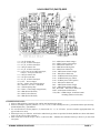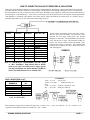
1
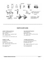
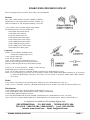
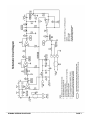
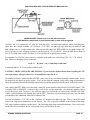
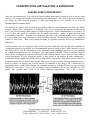
CONSTRUCTION, INSTALLATION, & OPERATION
DYNAMIC SPEECH PROCESSOR ©
Have you ever wondered why every AM or FM Rock broadcast station always sounds so loud, or why the sound
portion of TV commercials always seems louder than the program itself? The reason is that smart broadcasters
use exactly the same powerful principles of audio processing that are now available to you with the
Dynamic Speech Processor (DSP).
The nature of the human voice is such that it normally modulates a radio transmitter only about 30% on the
average. Almost all the “intelligibility” or readability of the voice is contained in the consonant sounds such as
B, K, S, etc. However these sounds contain very little average power. On the other hand the vowel sounds (A, E,
I, O, U) don’t add greatly to readability, but do contain high-intensity “spikes” or peaks that can easily
overmodulate a transmitter. Therefore if we can increase the energy of the consonant sounds relative to those of
the vowel sounds, the average audio power will be noticeably increased. The signal will come across with more
“punch” or “talk power.” With correct speech processing, it’s possible to increase the average modulation to
about 90%!
At the same time, the voice frequencies under 500 Hz and above 2500-3000 Hz don’t add much readability or
average power, and aren’t needed for voice communications typical of two-way radio. What’s needed is a circuit
that will cut off or “clip” the high-intensity peaks, increasing average modulation and at the same time reducing
the strength of the unnecessary voice frequencies. That’s the purpose of the DSP. Unlike all common CB power
mikes, the use of clipping is much more effective for radio communications. Power mikes are either ordinary
circuits that amplify all voice frequencies equally, or they operate on the principle of audio “compression.”
Compression simply amplifies the weaker voice elements relative to the peaks. These mikes are very sensitive to
background noises and AC hum on base stations. Many tests over the years have shown that compression isn’t
nearly as effective as clipping, and its actual increase in readability is only about 1 dB. Compare the two
photographs below, which clearly illustrate .the advantages of clipping. With the DSP there’s a very noticeable
difference in “talk power.” Up to 15 dB of clipping is quite acceptable to the ear, has little effect on voice
quality, and provides about 4 dB of true signal readability improvement. This 4 dB is equal to
©
Copyright 1979–2001 by L.M. Franklin. All rights reserved
CBC INTERNATIONAL · P.O. BOX 30655 · TUCSON AZ 85751 U.S.A.
TEL/FAX: (888) 434-9227, (520) 298-7980 · Email: [email protected]
more than doubling the effective transmitter power. A 4-watt CB sounds more like 10 watts! Further clipping up
to about 25 dB is tolerable under conditions of heavy interference (QRM). It adds another 1.5 dB of readability
to the signal, but the distortion in the voice quality starts to become noticeable.
Another advantage of clipping is that background noise and hum aren’t nearly as noticeable as they are in typical
audio compression mikes. That’s because the DSP doesn’t amplify the weak sounds relative to the strong sounds.
Instead it reduces the stronger, low readability peaks relative to the weak ones. The difference is very subtle but
the results often mean a dramatic increase in real talk power!
The main problem with clipping is that it creates harmonics that can cause bleedover to adjacent channels.
Proper harmonic filtering is essential and must never be ignored. In the DSP this filtering is easily done by
adding a few extra parts at its output to form a “Low Pass” filter, just like those used to reduce TVI.
Even a properly filtered clipping circuit can still overmodulate (more than 100%) and cause bleedover. Any
clipper circuit must also have some way to control its output level. In the DSP both the output level and the
amount of input clipping are fully adjustable using small trimmers. This means your mike audio is increased to a
much higher average power level but without causing needless interference. In other words, LOUD!
Over the years our Dynamic Speech Processor kit has undergone many changes to make it even more effective
and easier to build. Our current design uses the very reliable LM324 op-amp and can be installed in just about
any combination of radio and mike equipment. Two user options when building the kit make the DSP easily
compatible with both high- and low-impedance mikes, and most power mikes. We’ve included special holes in
the PC board for those rare times when extra RF or AC filtering may be needed. These options are fully
explained below and in the INSTALLATION section.
THEORY OF OPERATION
Refer to the Schematic Circuit Diagram, Page 7. The incoming mike signal is first coupled through C2, to an input
matching and gain level buffer circuit at A1. A1 is one of four sections of an LM324 quad op-amp IC. The user
can select several possible options here to make the DSP compatible with most low-impedance dynamic mikes,
power mikes, or high-impedance mikes. This is done by choosing among jumper wire combinations when
building the circuit. The gain of an op-amp is set mainly by the ratio of input resistance to feedback resistance.
Therefore separate pairs of resistors with different gain ratios are used at RL-1, RL-2, RH-1, and RH-2. The
impedance seen by the mike itself is generally whatever the amp’s input resistance happens to be, and the jumper
wires that connect between the “Z” holes and the “L” or the “H” holes can control this. The Schematic shows
jumpers set for a standard low-impedance dynamic type mike.
The majority of modern CB and Ham rigs use low-impedance mikes, typically 300Ω–1KΩ. Jumpering the “Z” to
“L” holes puts resistors RL-1 and RL-2 in the circuit. These are 1KΩ each which will provide a good impedance
match for this type of mike. Since radio operators now tend to use either power mikes or stock low-impedance
mikes rather than high-impedance mikes, the RH-1 and RH-2 resistor values were chosen to match power mikes.
Power mikes use amplifiers having about 5KΩ maximum output impedance, depending on the setting of the mike
control. This is considered low-impedance for our purposes. A true high-impedance mike has a crystal or
ceramic element, and is common in the older tube type CBs or high-power Ham transceivers. Those mike
impedances are usually in the range of 47KΩ–100KΩ.
___________________________________________________________________________________________________
DYNAMIC SPEECH PROCESSOR
PAGE 2
The problem with power mikes is that they tend to overdrive the input circuit of the DSP, causing self-oscillation
and squealing Selecting the “Z” to “H” input jumpers reduces much of the power mike gain. Since RL-1 and RL2 are equal A1 has no gain at all and acts only as a buffer. By jumpering RH-1 and RH-2 in the circuit there’s
now a voltage reduction of about 10:1, since RH-1 = 1KΩ and RH-2 = 100Ω. This makes a power mike much
more compatible with the DSP. If you have a true high-impedance mike (like the original non amplified D-104)
or an older tube type radio, replace RH-1 and RH-2 with 47KΩ–100KΩ resistors. This makes a good impedance
match with a zero-gain, buffered input at A1.
Continuing along, the signal couples through C3, VR1, and R3 to A2, the preamplifier. VR1 is the Clipping Level
adjustment. Clipping requires that a signal first be greatly amplified in voltage. The combination of R5 and
VR1/R3 sets the gain of A2, which at its minimum setting has a gain of approximately 1 (10K Ω ÷ [10KΩ + 220Ω
]) and can be increased to about 45 (10KΩ ÷ 220Ω). The output signal couples through C4 to A3, the next
amplifier stage. The value of C4 is chosen for the most natural sounding voice quality and can be any ceramic
disc capacitor from .001 µF to .1 µF. The .002 µF value was chosen by experimentation. As the value becomes
larger (closer to .1 µF), the voice sounds more bassy and “muddy.” The smaller value gives a good crisp voice
quality because it can pass more of the higher voice frequencies. The combination of R6 and C4 forms a highpass filter to reduce voice frequencies below about 500 Hz.
The output of A3 is coupled through C5 to the clipper circuit Two 1N914 fast-switching silicon diodes are wired
back to back, such that one clips on negative modulation peaks and one on positive peaks These diodes, D1 and
D2, are forward biased slightly by R9, R10, and R11 to make the clipping start more quickly. The resting DC
voltage at their anodes is about 0.82 VDC, which means any signal above this preset level is automatically
clipped. This ensures that at high modulation levels, clipping action will be almost constant.
Since clipping produces undesirable harmonics that cause channel “bleedover,” they’re removed first by a
low-pass filter consisting of R12 and C7. They’re further reduced along with unneeded voice frequencies above
3000 Hz by A4. A4 acts as both an amplifier and an active filter, with R13 and C8 being the filter elements. The
processed signal is coupled through C9 to the output level adjustment VR2.
Following VR2 are two output paths: one directly from its wiper (Hole #1) and one through R17 (Hole #2). In
most applications the output can be taken directly from Hole #1. In a few cases where it’s impossible to control
the transmit modulation level because the overall gain of the radio and processor together are too high, Hole #2
can be used. This puts another 10KΩ in series with the output to lower the audio level reaching the transmitter.
In true high-impedance input circuits you can replace R17 with a resistor of 47KΩ–100KΩ and use it with Hole
#2 for impedance matching. Most radios can use Hole #1 directly without changes. Please read the special
modification notes on Page 16 before you build the kit; these apply to many popular models.
The processor is powered from the radio’s main +13.8 VDC source. D3 is a 6.2 volt Zener diode that provides a
well regulated power source to the processor. RF is decoupled from the DC power supply by C1. Holes are
included on the circuit board for extra filter capacitors CF1 and CF2 (dotted lines). For RF filtering, CF1 can be
a .01 µF or .1 µF ceramic disc type. CF2 would be a large electrolytic of 10µF–100 µF and would help reduce
AC hum pickup if the DSP is powered by a poorly filtered radio or AC-to-DC converter. (These parts not
included in kit.) A small disc capacitor of .001 µF can sometimes help reduce RF feedback (squealing) in certain
situations; you would install this directly across the gray INPUT cable’s center and shield wires. RF chokes of
about 470 µH can also be used and would be wired in series with the INPUT or OUTPUT (or both) center
conductors. NOTE: Linear amps are common among CBers now, and most are very poorly designed. They are
guaranteed to cause feedback squeal and are not recommended when using the DSP.
___________________________________________________________________________________________________
DYNAMIC SPEECH PROCESSOR
PAGE 3
REFERENCES & SUGGESTED READING
RADIO HANDBOOK (any recent edition), by William I. Orr
MacMillan Publishing, 11711 N. College Av., Carmel, IN 46032. TEL: (800) 428-5331, (317) 573-2500.
THE RADIO AMATEUR’S HANDBOOK (any recent edition), by American Radio Relay League (ARRL),
225 Main St., Newington CT, 06111. TEL: (800) 243-7767, (203) 666-1541. FAX: (203) 665-1166.
SOLID-STATE DESIGN FOR THE RADIO AMATEUR. ARRL, address above.
LINEAR IC DATA BOOK
National Semiconductor Inc., 2900 Semiconductor Dr., P.O. Box 58090, Santa Clara, CA., 95052.
TEL: (800) 272-9959, (408) 721-5000. FAX: (408) 739-9803.
_________________________________________________________________________________
ASSEMBLY INSTRUCTIONS
PLEASE READ CAREFULLY BEFORE PROCEEDING!
NOTICE
This device will operate as advertised when properly constructed, installed, and adjusted.
CBC INTERNATIONAL has no control over the skill of the builder; therefore no warranty can be
given. We will accept for repair units built only from our own kits for $25 prepaid with returned
unit. NO BASKET CASES PLEASE!
Proper soldering is essential and poor solder joints are the single biggest cause of problems. Finished joints
should look shiny, never dull. Use only a small iron (25-45 watt) with a very fine round or slot tip to avoid
shorts. See the sketch at the top of the next page for soldering tips.
Assembly consists of stuffing the parts into the proper PC board holes as illustrated in the X-Ray View drawing,
Page 8. Check against the Schematic if you’re in doubt about the correct holes. Push all parts down tight,
wiggling back and forth if necessary as you press down. (See photo, Page 15.) The diodes and resistors will
bend naturally to the proper hole spacing.
NOTES
1. Pin #1 of the LM324 is clearly marked by a tab on the PCB. See sketch on next page.
2. Diodes must be installed with the banded [–] end in the correct hole as shown in the X-Ray View. The [–]
end is marked on the PCB for easy identification.
3. Save some of the cut off parts leads to use for the “Z,” “L,” or “H” jumper holes, as described in the
THEORY and INSTALLATION sections.
4. Observe polarity of electrolytic capacitors. The [+] ends are marked on the PCB, and usually the [–] ends
are marked on the plastic vinyl covering the capacitor body. The [+] lead is usually longer too.
5. If you’re building from our plans using your own parts, you’ll see a few extra PC foil pads and holes.
These are provided so the most common electronic parts sizes will fit in the PC hole spacings.
6. Recheck all work for shorts, solder bridges, and proper parts locations. Check proper polarities of
diodes and electrolytics. Holding the PCB up to a strong back light will easily show any possible shorts.
Clean off the solder flux with acetone or flux remover (Radio Shack #64-4330, etc.) for a professional
finish to your kit. This also makes it much easier to spot bad solder joints or bridges.
If you expect your kit to work properly, try very hard to install the parts neatly and correctly, as shown in
the X-Ray View and the photograph. Press all parts down tight against the PC board; rock the diode or
resistor leads back and forth while pressing, until they fit flush against the PC board.
___________________________________________________________________________________________________
DYNAMIC SPEECH PROCESSOR
PAGE 4
___________________________________________________________
PARTS SUPPLIERS
CIRCUIT SPECIALISTS INC.
220 S. Country Club Dr. #2
Mesa AZ 85210
TEL: (800) 528-1417, (480) 464-2485
FAX: (480) 464-5824
www.cir.com or www.web-tronics.com
MOUSER ELECTRONICS
1000 N. Main St.
Mansfield TX 76063
TEL: (800) 346-6873, (817) 804-3888
www.mouser.com
DIGIKEY CORP.
701 Brooks Av. South
P.O. Box 677
Thief River Falls MN 56701
TEL: (800) 344-4539, (218) 681-6674
FAX: (218) 681-3380
www.digikey.com
ALLIED ELECTRONICS
(over 80 locations all over the U.S.)
Main HQ: 7410 Pebble Dr.
Fort Worth TX 76118
TEL: (800) 433-5700, (817) 336-5401
FAX: (817) 595-6444
www.avnetallied.com
___________________________________________________________________________________________________
DYNAMIC SPEECH PROCESSOR
PAGE 5
DYNAMIC SPEECH PROCESSOR PARTS LIST
Parts are designated by their locations on the X-Ray View and Schematic.
Resistors
VR1, VR2 = 10KΩ (Mouser 32AA401, 32RH401, 32RW401,
DigiKey K4A14, Circuit Specialists #32AA401, 32JR401, etc.)
These are miniature 0.1 watt, horizontal mounting, 8 or 10 mm.
1 each, 330Ω ½-watt, 5% carbon (orange-orange-brown)
The following are all ¼-watt, 5% carbon types:
1 each, 100Ω (brown-black-brown)
1 each, 220Ω (red-red-brown)
9 each, 1KΩ (brown-black-red)
4 each, 10KΩ (brown-black-orange)
1 each, 47KΩ (yellow-violet-orange)
1 each, 100KΩ (brown-black-yellow)
1 each, 180KΩ (brown-gray-yellow)
2 each, 470KΩ (yellow-violet-yellow)
1 each, 1MΩ (brown-black-green)
Capacitors
(NOTE: You can substitute Tantalums for the
electrolytics at slightly higher cost.)
1 each, 150 pF ceramic disc
2 each, .002 µF ceramic disc
1 each, .01 µF ceramic disc (Radio Shack 272-131)
These are all low-voltage (25-50 VDC) types which are
physically small enough to fit across the PCB hole spacings.
4 each, 4.7 µF 25 VDC electrolytic. Radial or axial lead types.
(Radio Shack 272-1012 axial, 272-1024 radial.)
1 each, 1 µF 25 VDC electrolytic or tantalum. Radial or axial lead type. (Radio Shack 272-1434)
NOTE: For 1 µF electrolytic you can sub: 0.47 µF electrolytic, 0.47µF ceramic (Radio Shack #RSU11298320), 0.1 µF electrolytic
or metal film (Radio Shack #276-1069, #276-1053), 0.22 µF ceramic or electrolytic (Radio Shack #RSU11298312,
#272-1070).
Diodes
2 each, 1N914 or 1N4148 type fast-switching silicon (SK3016, ECG177, Radio Shack 276-1122, etc.)
1 each, 6.2 volt, ½-watt Zener (1N4735A, 1N5234B, Radio Shack #276-561 or #RSU-11673498, ECG5013A, SK3058, etc.)
Miscellaneous
1 each, LM324 quad op-amp (ECG987, SK3643, Radio Shack 276-1711, etc.)
1 each, 14-pin DIP IC socket. (Radio Shack 276-1999.) Highly recommended!
1 each, Dynamic Speech Processor PC board
1 piece each, RED and BLACK #22 AWG stranded or solid hookup wire. (Radio Shack 278-1218, 278-1224.)
1 piece , RG 174/U or similar shielded audio cable. (Radio Shack 278-512, Alpha #2254/1, Mouser #178-1803M, etc.)
A complete kit is available for $38 including shipping from:
CBC INTERNATIONAL · P.O. BOX 30655 · TUCSON AZ 85751 USA.
TEL & FAX: 1-888-I-FIX-CBs (1-888-434-9227) · Local: (520) 298-7980
Internet: www.cbcintl.com · Email: [email protected]
___________________________________________________________________________________________________
DYNAMIC SPEECH PROCESSOR
PAGE 6
___________________________________________________________________________________________________
DYNAMIC SPEECH PROCESSOR
PAGE 7
X-RAY VIEW TOP (PARTS) SIDE
C1 = .01 µF ceramic disc
C2 = 4.7 µF, 25 VDC electrolytic
C3 = 4.7 µF, 25 VDC electrolytic
C4 = .002 µF ceramic disc
C5 = 4.7 µF, 25 VDC electrolytic
C6 = 1 µF or 0.47 µF 25 VDC electrolytic,
or 0.1µF—0.22 µF ceramic disc
C7 = .002 µF ceramic disc
C8 = 150 pF ceramic disc
C9 = 4.7 µF, 25 VDC electrolytic
CF1, CF2 — See text Page 3.
D1, D2 = 1N914, fast-switching silicon
D3 = 1N4735A, 6.2 volt, ½-watt Zener
IC1 = LM324 quad op-amp
R1 = 330Ω ½-watt (orange-orange-brown)
R2 = 1KΩ (brown-black-red)
R3 = 220Ω (red-red-brown)
R4 = 1KΩ (brown-black-red)
R5 = 10KΩ (brown-black-orange)
R6 = 47KΩ (yellow-violet-orange)
R7 = 1KΩ (brown-black-red)
R8 = 1MΩ (brown-black-green)
R9 = 1KΩ (brown-black-red)
R10 = 10KΩ (brown-black-orange)
R11 = 1KΩ (brown-black-red)
R12 = 100KΩ (brown-black-yellow)
R13 = 180KΩ (brown-gray-yellow)
R14 = 470KΩ (yellow-violet-yellow)
R15 = 1KΩ (brown-black-red)
R16 = 10KΩ (brown-black-orange)
R17 = 10KΩ (brown-black-orange)
RL1, RL2, RH1 = 1KΩ (brown-black-red)
RH2 = 100Ω (brown-black-brown)
VR1, VR1 = 10KΩ trimpot, 10 mm horizontal
mounting (Mouser #32AA401)
___________________________________________________________________________________________________
CONSTRUCTION NOTES
1. Observe diode polarities. Install D1, D2, and D3 with banded ends as shown.
2. Observe electrolytic capacitor polarities. C2, C3, C5, C6, C9 will normally have the [–] end marked on the capacitor body,
and the PCB has the [+] end marked.
3. Use cut off lead wires for the jumpers (“J”) between the “Z,” “L,” or “H” holes. (See text; install in appropriate holes for
type of mike to be used.)
4. Electrolytics may be either the axial lead or radial lead type; holes are provided for both. (Radials are shown with dotted
circle; C6 may also be a disc capacitor.)
5. Parts values aren’t critical except C7, R13, C8, R14 for filter. Substitute next standard value up or down if you can’t find
exact parts.
___________________________________________________________________________________________________
DYNAMIC SPEECH PROCESSOR
PAGE 8
HOW TO FIGURE THE VALUE OF RESISTORS & CAPACITORS
These parts use the Electronics Industry Association (EIA) standard marking. Resistors have always had a simple color code, but
nowadays many disc and mica capacitors use EIA markings. (Especially true when dealing with Japanese parts.) The information
here should make it very easy to figure the values of these parts. Remember, many capacitors will have the values marked directly in
micro farads (µF.) or picofarads (pF.). After a while you will easily see from the physical size of the capacitor what the approximate
value should be. For example, a disc marked “.005” means .005 µF, while a disc marked “68” means 68 pF. A 0.1 µF disc is always
physically larger than a .01 µF disc of the same voltage rating, and so on
RESISTORS
COLOR
1st DIGIT
Black
Brown
Red
Orange
Yellow
Green
Blue
Violet
Gray
White
Gold
Silver
2nd DIGIT
0
1
2
3
4
5
6
7
8
9
0
1
2
3
4
5
6
7
8
9
—
—
—
—
MULTIPLY BY
1
10
100
1000
10,000
100,000
1,000,000
10,000,000
100,000,000
1,000,000,000
0.1
Typical carbon composition resistors like those used in
most kits have four color bands. The first three colors
represent the first digit, second digit, and decimal
multiplier, in that order. The fourth band is the tolerance
value. Our kits use 5% types. This means that a 1KΩ, 5%
resistor can measure between 950Ω and 1050Ω. (The
same tolerances apply to capacitors.) The tolerance band
is always silver or gold, so it’s easy to know which end to
start counting from.
0.01
NOTE: K = 1,000 (KILO); M = 1,000,000 (MEGA). Thus 10K = 10,000
Ω , 10M = 10,000,000Ω . Begin with the GOLD or SILVER
band on your right. Then read from left to right to get the
first digit, second digit, and decimal multiplier. SILVER 4th
band = 10%; GOLD 4th band = 5%; no 4th band = 20%.
_________________________________________________________________________________
DISC CAPACITORS (in pF)
IF 3rd CAPACITOR
NUMBER IS
0
1
MULTIPLY
BY
none
10
151K =
103M =
20%
472K =
202 =
EXAMPLES:
15 x 10 = 150 pF, 10%
10 x 1,000 = 10,000 pF or 0.01 µF,
47 x 100 = 4700 pF or 0.0047 µF, 10%
20 x 100 = 2000 pF or 0.002 µF
2
100
3
1,000
4
10,000
NOTE: Tolerance letter may follow:
J = 5%; K = 10%; M = 20%
Mica capacitors are generally 5% and use the same code; so 270J = 27 x 1 = 27 pF, 5%, and 271J = 27 x 10 = 270 pF 5%, etc.
Capacitors with no tolerance letter are read directly: “360” = 360 pF.
___________________________________________________________________________________________________
DYNAMIC SPEECH PROCESSOR
PAGE 9
INSTALLATION
The DSP connects in series with the mike and the main audio input circuit of the radio. Operating power comes
directly from the radio. The DSP is meant to fit inside the radio permanently; however instructions for external
box mounting are shown later. With box mounting it would be best to power the unit directly from a 9-volt
battery. Two PCB mounting holes are provided for bolting the PCB using 6/32 or 4/40 nuts and bolts. If washers
are used, be very careful that they don’t short out to any PCB foil traces. If you don’t want to bolt it in, the unit
can simply be laid inside the radio’s cabinet after adjustment with the solder side up to prevent shorts. Avoid
mounting in the area of the RF power circuit. This area is near the antenna coax socket at the rear or along one
side of the frame.
The DSP is soldered to the inside of the mike socket where the audio line and ground are located. If the radio
doesn’t use a socket, you’ll have to follow the mike cord into the main chassis and determine which wire is
which. Many newer models use ribbon cables to tie the front panel’s PCB to the main PCB; this may require a
service manual or schematic to find the exact wire.
If you don’t have a circuit diagram of the radio, you can usually figure out which mike wire is which, as explained
next.
All transceivers use either relay or electronic T/R switching. Relays are more expensive, so only the older
23-channel SSB rigs, a few of the better old 23-channel AM rigs, and some Ham rigs use relay switching. All the
rest use electronic switching. You can decide which type you have in two easy ways:
1. Look inside on the main radio PC board for the relay, which is a large rectangular plastic object about 1"
long. If you see one, key the mike and watch to see if the relay contacts move; a few rigs contain extra
relays that are used for other than T/R purposes.
2. Unplug the mike. If you can still hear noise from the speaker, you most likely have relay switching;
electronic switching disconnects one side of the speaker circuit on Transmit.
CAUTION: A few rigs, like some Realistics with the 5-pin DIN socket, have special shorting terminals so
that the speaker will still be heard, even with the mike unplugged. However these rigs are still
electronically switched, so be aware. Some other exceptions are the Uniden µPD2824 SSB chassis
(Cobra 146GTL, President AR-144, etc.) and export rigs such as the Cobra 148GTL-DX.
The majority of CBs use either the 5-pin DIN socket, a 6-pin DIN, or 4-pin or 5-pin male socket with threaded
coupling nut. Unless you have the radio’s schematic diagram, you must figure out which wire performs which
function. To do this, use a piece of wire or a clip lead, touching it to pairs of socket terminals and observing what
happens. You should find the following:
1. One pair will key the transmitter. (GROUND plus TX.)
2. One pair will cause the speaker to be heard. (GROUND plus RX.)
3. The fourth wire is the mike audio line you are looking for. The one wire that was common to all the other
functions is the ground terminal. If you have an ohmmeter, check each terminal by connecting one ohmmeter
lead to the black [–] power connection of the radio, and the other lead to each socket pin. The one socket
connection that shows zero ohms is the ground or “common” terminal.
Once you know the ground terminal you can connect across it and the other terminals, one by one. You’ll find that
one terminal keys the Transmitter, and one causes the speaker to be heard. If the socket only has four terminals,
the remaining terminal logically must be the mike’s audio terminal. If the radio uses a 5- or 6-pin socket, there
may be more than one ground because only four wires are needed for electronic T/R switching.
___________________________________________________________________________________________________
DYNAMIC SPEECH PROCESSOR
PAGE 10
On these rigs you can also locate the mike audio terminal by either shorting the pair that keys the Transmitter, or
use the radio’s mike to key the Transmitter. Then touch each of the other terminals with your finger while
listening to the carrier on another CB tuned to the same channel. When you touch the mike audio line with your
finger, you should hear a carrier hum on the other radio.
A few rigs use remote controls (Squelch, Volume, Channel Select) built into the mike, and may require the actual
circuit diagram to find the specific connections. Shown below are the mike plug numbers for the most common
CB socket types.
When you’ve located the mike audio and ground pins, unsolder the audio wire from its pin. Connect this wire
instead to the center conductor of the GRAY shielded cable, on the OUTPUT side of the DSP. (The OUTPUT
cable is the one coming from the PCB holes marked “G,” “1,” or “2.”) The shield at the loose cable end isn’t
needed, and can be cut off or taped back against the vinyl covering.
Now connect the loose cable end of the DSP’s INPUT side to the mike audio and ground pins on the mike socket.
(The INPUT cable is the one connecting to the “G” and the “IN” holes on the PC board.) Connect the center
conductor of the GRAY cable to the now-empty socket pin, and the shield to the ground terminal right along with
whatever radio wire is already on that pin. As shown on the next page, you have simply installed the Processor’s
audio INPUT and OUTPUT cables in series with the radio’s mike audio line.
NOTES
1. Many newer radios (Cobra 140/142GTL, etc.) connect a separate small PC board to the mike socket pins.
This board has all the same functions (TX, RX, AUDIO, GROUND). Locate and unsolder the audio wire,
and tack-solder the GRAY cable on to the small mike PC board instead.
2. A few old relay type CBs and HAM rigs use a small shielded wire running to the mike socket, which
carries the audio signal. If you have this type, you can unsolder both center wire and shield, and connect to
center and shield of the GRAY DSP output cable; this provides better audio shielding.
3. Make sure you have installed the jumper wires, as described in the THEORY and the ASSEMBLY
sections, to the correct holes that match the type of mike you are using. To repeat: both jumper wires
should connect between the “Z” and “L” holes for stock low-impedance mikes, and between the “Z” and
“H” holes for power mikes. If yours happens to be an old tube type rig, or the mike is crystal or ceramic,
these are high-impedance circuits. In such cases remove resistors RH-1 and RH-2 and replace both with
47KΩ resistors. (Not provided.) In addition the center wire of the GRAY output cable is moved over to
the #2 output hole, and R17 (10KΩ) is replaced with a 47KΩ resistor. These changes for high-impedance
circuits will ensure the proper impedance matching. Refer to the X-Ray View and Circuit Diagram for
parts locations.
___________________________________________________________________________________________________
DYNAMIC SPEECH PROCESSOR
PAGE 11
BASIC PROCESSOR INSTALLATION IN SERIES WITH MIKE AUDIO/LINE
NEWER RADIOS: Colored wires on all the mike socket pins.
OLDER RADIOS: Colored wires or small shielded cable on mike audio and ground.
All that’s left is to connect the +12 volts DC from the radio. All solid-state transistor radios, including base
types, have this voltage available. (It’s closer to +13.8 VDC.) On tube type rigs, there may be both low- and
high-voltage sources, or high-voltage only. But you can still connect the DSP’s RED wire to a high-voltage +DC
source by using a series dropping resistor to get the required +12-14 volts DC. Since the DSP draws about 24
mA. (0.024 Amp) total current, use Ohm’s Law to calculate the required series resistor.
For example if a +250 VDC power source is available in the radio, you want to drop [250 –12] = 238 volts of
that. The series dropping resistor would be:
R=E
÷ I;
R = [250 — 12] ÷ 0.024 Amp = 9,916 ohms.
A standard 10KΩ, 1 or 2 watt resistor could be used.
CAUTION—HIGH VOLTAGES ARE LETHAL! If you have the slightest doubt about installing the DSP
in a high-voltage, tube type transceiver, let a qualified technician do it!
On mobiles and bases, connect the BLACK DSP power wire to any convenient ground or common point. It may
be marked on the chassis or power socket. You can also find the common circuit foil by using an ohmmeter to
check for continuity between the intended connection point and the ground you already know on the mike socket.
Now connect the DSP RED wire to the radio’s main DC power located at the ON/OFF/VOLUME control. This
is usually RED or ORANGE. Connect to the switched side, not the input side. On solid-state mobiles, this is
always the proper point. However a few old base transceivers switch the AC mains at the ON/OFF/VOLUME
control; connection there will instantly blow out the DSP! Those base rigs are extremely rare now, but if in doubt
you should test the connection point with a voltmeter first.
You can also find the +13.8 VDC on the “converter” PC board used in base type rigs. This is a small PC board
close to the large power transformer on the chassis. The +DC is typically available at the Emitter of the large
PNP series regulator transistor on this board. The following shows base and mobile hookups. Don’t rely solely
on the GRAY wire shield for the DC return path; always use the BLACK wire!
___________________________________________________________________________________________________
DYNAMIC SPEECH PROCESSOR
PAGE 12
NOTE: Additional PCB holes are provided for two types of filter capacitors, if needed. These are labeled “CF1” and
“CF2” on the X-Ray View and Circuit Diagram. Occasionally the use of a linear amplifier, high antenna SWR, or poor radio
filtering will cause RF feedback or “squealing” during TX. Sometimes an AC hum will appear on the transmitted signal due
to poor AC filtering in a base radio. A .01 µF or .1 µF ceramic disc at “CF1” may help the RF feedback problem, and an
electrolytic capacitor of 10-100 µF at “CF-2” should cure the AC hum problem. Holes are provided to fit many types of
capacitors. This problem is rare and generally only happens if you put the DSP in an external plastic box with long power
wire leads from the rig or from a separate DC supply. Before adding such capacitors, read the special notes on Page 16
first; most problems will be cured using those tips instead.
Many people have asked about installation in a separate box external to the radio, with an IN/OUT switch for those
occasions when speech processing isn’t needed. Shown next is the basic hookup. You would need to install suitable mike
plugs and sockets on a metal mini-box, or run a bunch of loose wires to the radio. On base rigs it’s best to use 9-volt battery
power instead of the main AC to minimize hum or RF pickup. You’ll need a 3PDT switch to kill the battery power in the
“OUT” position any time the DSP isn’t in use.
NOTE: Although we are including information for an external hookup, this isn’t recommended due to the problem of RF
feedback in long wires. Install it this way at your own risk! A much better idea, if your rig has a MIKE GAIN control, is to
use that to control clipping levels. Install the DSP internally and set it to maximum clipping. Then adjust the MIKE GAIN as
needed.
ADJUSTMENT & OPERATION
Normally an oscilloscope should be used for proper adjustment of any speech processor. Since this is a very expensive
instrument and usually only available to technicians, an inexpensive Modulation/Power/SWR type meter (or the rig’s own, if
present) can be used instead. The basic idea is to set the INPUT clipping pot VR1 for the desired amount of clipping while
adjusting the VR2 OUTPUT pot for 100% modulation of the transmitter. Both adjustments will interact slightly so that if
clipping is turned down, the output may have to be turned up, and vice-versa. Since most operators install the DSP
permanently inside the transceiver, this should be a one-time, set-it- and-forget-it operation.
___________________________________________________________________________________________________
DYNAMIC SPEECH PROCESSOR
PAGE 13
Have a friend listen to your transmitted signal, or else use a second radio tuned to the same channel. Begin with
VR1 and VR2 trimmers at their midpoint. The following sketch
shows the direction of maximum levels for both adjustments.
Speak into the mike in a normal voice (or whistle) while turning the
OUTPUT trimmer VR2 for 100% modulation. Then turn up the
INPUT trimmer VR1 until the voice sounds strong and “punchy”
without being too fuzzy, harsh, or distorted. The voice may sound
slightly less natural but otherwise quite clear. Don’t advance either
trimmer up too far or you may get self-oscillation (squealing) due to
the overall high gain of the combined DSP, power mike (if used), and
radio circuits all working together. The majority of newer rigs have
very high audio gain and may oscillate with over adjustment.
The DSP is designed to provide approximately the same peak-peak audio output (about 3.0 V) as the output from a
typical dynamic mike preamp. If you can’t lower the OUTPUT far enough to prevent overmodulation, move the
center conductor of the OUTPUT cable over to the #2 hole. This puts another 10KΩ series resistance in line
through R17 to reduce the OUTPUT level. If the radio’s modulation limiting circuit (AMC) or control pot
was turned up or removed, it should be restored to normal. Without it you will severely overmodulate and
cause lots of channel bleedover. Those modifications aren’t needed at all with a properly adjusted DSP.
Remember, the whole idea is to maintain near 100% modulation, but no more!
The squeal problem is very common in many newer Uniden SSB rigs, such as the Cobra 140/142GTL, Cobra
148/2000GTL, and any µPD2824 SSB type chassis. A .001 µF disc capacitor placed directly across the center
and shield of the GRAY INPUT cable at the mike socket should stop it. Sometimes a second .001 µF capacitor is
needed inside the mike itself. Don’t get carried away though or you may start losing the higher audio frequencies.
Also keep the BLACK power wire as short as possible and solder it directly to the nearest metal transformer. In
really tough cases, add one or more RF chokes of about 470 µH in series with the INPUT and/or OUTPUT leads
to decouple all the stray RF. See Page 16 for details.
When your only test instrument is a DC voltmeter, you can still get a rough test for clipping action by placing the
[+] lead at the junction of R10/D1/D2. It normally reads 0.9 VDC here; with VR1 at maximum, a loud whistle
into the mike will deflect the voltage downwards.
Power mikes are really not needed, not recommended, and often complicate the installation. The D104 types are
the worst! We can’t guarantee they’ll work. If you insist on trying, be sure to move the input jumpers from the
“Z” and “L” holes to the “Z” and “H” holes. This adds a 10:1 voltage reduction to prevent the power mike from
overdriving the DSP. The power mike’s control will then make a convenient clipping adjustment control: By
setting VR1 for maximum you can use the mike’s control to change the clipping as desired.
If your radio has a MIKE GAIN control, this makes an even better method. Set that and VR1 to maximum,. set
VR2 for 100% modulation, then use a stock mike with the DSP to conveniently control the clipping level.
Good DX-ing!
_________________________________________________________________________________________
If you need help finding the right audio, ground, or DC power connections in your rig, we’ll try to help. Send a
#10 (business size) self-addressed stamped envelope and the exact manufacturer’s make or model of radio to:
CBC INTERNATIONAL · P.O. BOX 30655 · TUCSON AZ 85751 U.S.A.
___________________________________________________________________________________________________
DYNAMIC SPEECH PROCESSOR
PAGE 14
___________________________________________________________________________________________________
DYNAMIC SPEECH PROCESSOR
PAGE 15
IMPORTANT INSTALLATION NOTICE
In many installations squeal will occur unless certain modifications are made. The squeal is caused by either RF
feedback or excess audio gain, and is specific to certain radios. The most common models having this problem
include all Uniden and Uniden “clone” SSB models, such as: Cobra 140GTL, 142GTL, 148GTL, 2000GTL,
2010GTL, Uniden GRANT, GRANT XL, MADISON, WASHINGTON, Uniden µPD2824 SSB types, and all
Uniden “clone” export models like Galaxy, etc. There may be other brands and models as well.
You must decouple the excess RF if this is the problem. If the following steps don’t eliminate the squeal, then try
the methods described below under “EXCESS AUDIO GAIN.”
RF DECOUPLING:
Install a ceramic disc capacitor (470 pF to .001 µF) directly across the mike audio and ground (chassis common,
not metal case) right at the inside of the mike socket itself, keeping the leads very short. A .001 µF capacitor is
included in our kit. In addition, you may need another one soldered directly across the DSP foil traces where the
INPUT gray cable enters the PC board. Don’t use any capacitor larger than about .001 µF, or you may lose some
of the higher audio frequencies.
Also solder the BLACK [-DC] power wire to the shortest, most direct chassis common point possible. Usually
this will be at one of the metal tuning transformer cans on the radio PC board. Solder will stick to these cans.
NOTE: Do not run the BLACK power wire back to the rear DC input point. Besides the long wire
length, the DC input socket is RF-isolated from chassis common by a small choke in most radios,
and could create a ground loop that makes the problem even worse. Ground the BLACK wire only
to the same common point as the audio ground, metal transformer cans, etc.
In the Uniden MB8719 type PLL radios, it may help to power the RED lead from Pin #1 of the MB3756 voltage
regulator IC (+8 VDC), which provides somewhat isolation and filtering than the +13.8 VDC bus.
For really stubborn cases, you may need to add an RF choke of about 470 µH in series with either the INPUT or
OUTPUT (or both) center conductors of the GRAY cables. Some rigs like the Uniden HR2510 will definitely
need this modification. Put the RFC directly on the main PC board where the audio signal enters from the mike
socket PC board. (We stock these chokes in a 5-pack only, $6.00 postpaid.)
EXCESS AUDIO GAIN:
This is an equally common problem caused by the high gain of the DSP in series with all the existing audio gain
already in the radio. First, make sure you’ve used the #2 OUTPUT hole, which adds the 10KΩ series resistance
of R17. Next, replace R12 (100KΩ, brown-black-yellow) with 470KΩ (yellow-violet-yellow) which will
sharply reduce the DSP’s total gain. An extra 470KΩ resistor is included with our kit. Refer to the X-Ray View
on Page 8 to locate R12.
All the radio types listed on this page will need this minor parts change. We suggest you do it while you’re
building the kit and avoid having to unsolder the 100KΩ resistor at all.
___________________________________________________________________________________________________
DYNAMIC SPEECH PROCESSOR
PAGE 16