1
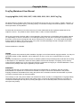
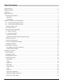
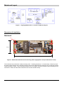
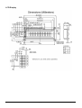
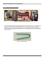
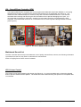
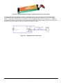
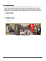
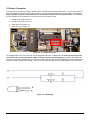
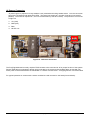
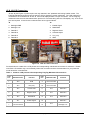
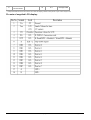
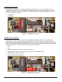
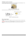
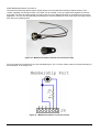
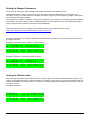
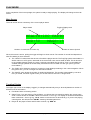
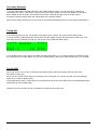
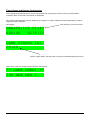
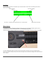
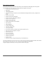
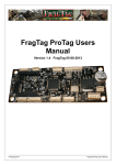
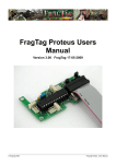
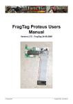
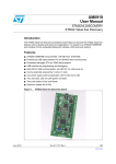
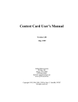
FragTag Mainboard Users Manual Version 3.50 FragTag 29-10-2012 © FragTag 2012 FragTag Mainboard Users Manual Copyright Notice FragTag Mainboard User Manual Copyright 2004, 2005, 2006, 2007, 2008, 2009, 2010, 2011, 2012 FragTag All rights reserved. No part of this work may be reproduced in any form or by any means – graphic, electronic, or mechanical, including photocopying, recording, taping, or information storage and retrieval systems – without the written permission of the publisher. Products that are referred to in this document may be either trademarks and/or registered trademarks of the respective owners. The publisher and the author make no claim to these trademarks. While every precaution has been taken in the preparation of this document, the publisher and the author assume no responsibility for errors or omissions, or for damages resulting from the use of information contained in this document or from the use of programs and source code that may accompany it. In no event shall the publisher and the author be liable for any loss of profit or any other commercial damage caused or alleged to have been caused directly or indirectly by this document. Feb 2012 Melbourne, Australia. TERMS FragTag products are protected by both Australian Copyright Law and international copyright treaties. You may not seperately publish, market, distribute, sell or sublicense, for fee or no fee, the Licensed Product or any part thereof. FragTag will endeavour to provide free access to software updates to all purchased products that are still currently in development. The distribution method of these updates is at the sole discretion of FragTag, and for security reasons product updates may involve returning electronic components to FragTag or a licensed distributor. In this instance return postage costs may be payable by the purchaser. WARRANTY FragTag warrants that your purchased product will perform substantially in accordance with the provided documentation for a period of 12 months from the date of receipt. In the event of deviations in the product, FragTag will make a reasonable effort to bring the product into conformance with the documentation to provide you with a corrected version as soon as possible. This warranty is void if the product failure has resulted from abuse, accident, or misapplication. FragTag's liability is limited to refund of the money paid for the product, and in no event will FragTag be liable for any indirect or consequential damages that may arise (including damages for loss of business profits, business information, or other pecuniary losses). © FragTag 2012 Page 2 of 51 Table Of Contents Copyright Notice .................................................................................................................................................... 2 Table Of Contents ................................................................................................................................................. 3 Introduction............................................................................................................................................................ 6 Mainboard Layout .................................................................................................................................................. 7 Dimensions & Installation ................................................................................................................................... 7 Mainboard ...................................................................................................................................................... 7 LCD Display.................................................................................................................................................... 8 Hardware Installation and Configuration................................................................................................................. 9 IC1 – Central Processing Unit (CPU).................................................................................................................. 9 IC2 – Sound Effects Controller (SFX)............................................................................................................... 10 Mainboard Sound List ................................................................................................................................... 10 VR1 Volume Control ........................................................................................................................................ 10 VR2 LCD Contrast Adjustment ......................................................................................................................... 12 J1 – Power Connector ...................................................................................................................................... 12 J2 – Controls Connector................................................................................................................................... 14 J3 Output Connector..................................................................................................................................... 15 Notes about the Alternating Fire Special Config............................................................................................ 16 J4 Sensor Connector........................................................................................................................................ 17 J5 & J6 LCD Connectors .................................................................................................................................. 18 Pin outs of supplied LCD display:.................................................................................................................. 19 J7 Speaker Connector...................................................................................................................................... 20 J8 Expansion Connector .................................................................................................................................. 20 Odin Master Controller Connections ............................................................................................................. 21 Weapon Special Output................................................................................................................................ 21 Software Users Guide.......................................................................................................................................... 23 Version Number ............................................................................................................................................... 23 Configuration Data ........................................................................................................................................... 23 Configuration Summary ................................................................................................................................... 23 Configuration Menus ........................................................................................................................................ 24 Game Style .................................................................................................................................................. 24 Health........................................................................................................................................................... 25 Magazines .................................................................................................................................................... 25 Sound Set..................................................................................................................................................... 25 Signal Format ............................................................................................................................................... 26 Team ............................................................................................................................................................ 26 Player ID ...................................................................................................................................................... 26 Advanced Configuration ............................................................................................................................... 27 Advanced Config: Friendly Fire..................................................................................................................... 27 Advanced Config: Range .............................................................................................................................. 27 © FragTag 2012 Page 3 of 51 Advanced Config: Game A/B........................................................................................................................ 28 Advanced Config: Safety Fire Mode enable .................................................................................................. 28 Advanced Config: Disable Hit Led ................................................................................................................ 28 Advanced Config: Death Time ...................................................................................................................... 29 Advanced Config: Respawn Time ................................................................................................................. 29 Advanced Config: Simulation: Bleed Effect................................................................................................... 29 Advanced Config: Simulation: Damage Multiplier ......................................................................................... 30 Advanced Config: Simulation: Physical Magazines....................................................................................... 30 Advanced Config: Auto Respawn.................................................................................................................. 30 Confirming Settings ...................................................................................................................................... 31 Loading Default Configuration .......................................................................................................................... 31 Setting the Weapon Parameters ................................................................................................................... 32 Setting the iButton enable............................................................................................................................. 32 Setting the Weapon Special Output Mode .................................................................................................... 33 PLAY MODE ....................................................................................................................................................... 34 Main Screen..................................................................................................................................................... 34 Toggling Display .............................................................................................................................................. 34 Fire Modes....................................................................................................................................................... 35 Reloading......................................................................................................................................................... 35 Secondary Weapons........................................................................................................................................ 36 Taking Hits....................................................................................................................................................... 36 The Hit LED ..................................................................................................................................................... 36 Dieing .............................................................................................................................................................. 37 Respawning ..................................................................................................................................................... 37 ADVANCED TOPICS .......................................................................................................................................... 38 LCD Backlight .................................................................................................................................................. 38 Near Miss......................................................................................................................................................... 39 Target .............................................................................................................................................................. 39 Timed Games and Remote Configuration ........................................................................................................ 40 Gun Status....................................................................................................................................................... 41 iButton System................................................................................................................................................. 41 Bleed Simulation.............................................................................................................................................. 42 Stuns ............................................................................................................................................................... 43 Explosive and Radiation Damage .................................................................................................................... 44 Anti-Cheat Functions........................................................................................................................................ 45 Power Logging.............................................................................................................................................. 45 Sensor Failure .............................................................................................................................................. 45 Field Code .................................................................................................................................................... 45 Data Logging and Scoring ................................................................................................................................ 46 Upgrading the Firmware................................................................................................................................... 49 Items Needed ............................................................................................................................................... 49 © FragTag 2012 Page 4 of 51 Procedure..................................................................................................................................................... 49 Troubleshooting ............................................................................................................................................ 51 © FragTag 2012 Page 5 of 51 Introduction Welcome to FragTag, a highly advanced, dual format commercial ‘laser’ tag combat simulation system that follows open standards. The FragTag mainboard is a hardware and software package that uses state of the art electronics to receive, process and transmit low power infra red (IR) light signals tens to hundreds of meters. These signals carry coded data that details such things as the transmitting player identification and associated team membership among other things. © FragTag 2012 Page 6 of 51 Mainboard Layout Figure 1. FragTag Mainboard v1.1/1.2 main component layout Dimensions & Installation Mainboard 0,0 120.69 3.6 9 9 42.45 33.45 33.45 3.6 120.69 124.25 Figure 2. Mainboard dimensions and mounting holes highlighted in red (all dimensions in mm). The mainboard is provided with 4 (M4) mounting holes. Insulating washers (i.e. not electrically conductive) must be used on both surfaces of the mounting holes to prevent the mainboard from shorting to any conductive surface inside the tag gun casing. Care must also be taken not to over tighten mounting screws to prevent damage to the mainboard. Failure to follow these instructions will void the limited warranty. © FragTag 2012 Page 7 of 51 LCD Display © FragTag 2012 Page 8 of 51 Hardware Installation and Configuration IC1 – Central Processing Unit (CPU) IC1 CPU Figure 3. IC1 Central Processing Unit (CPU) The FragTag Mainboard operates with a pre-programmed microcontroller (see Figure 3). The mainboard uses a 28-pin narrow IC socket for easy CPU installation/removal. Care must be exercised when inserting and removing the CPU so as to prevent damaging the IC pins. It is recommended the operator is sufficiently ‘earthed’ to prevent static electricity from damaging the CPU. An ‘IC extraction tool’ is also recommended for removing and inserting the CPU (refer Figure 4). Bent or otherwise damaged CPU pins are not covered under the limited warranty. Figure 4. IC extraction tool. © FragTag 2012 Page 9 of 51 IC2 – Sound Effects Controller (SFX) The FragTag Mainboard is equipped with a pre-programmed WinBond© ChipCorder ISD2560, or a FragTag HQ-SFX sound module, for storing all the required sound effects for the mainboard (see Figure 5). The mainboard uses a standard 28-pin IC socket for easy SFX Controller installation/removal. Care must be exercised when inserting and removing the SFX Controller so as to prevent damaging the IC pins. It is recommended the operator is sufficiently ‘earthed’ to prevent static electricity from damaging the SFX Controller. We recommend the use of an ‘IC extraction tool’ for removing and inserting the SFX Controller (refer Figure 4). IC2 SFX Figure 5. IC2 Sound Effects Controller (SFX) Mainboard Sound List The SFX controller does come pre-recorded with a set of quality sound effects, however, the following information is provided for those who may wish to customize their sound effects. Refer to FragTag Sound Order manual for details. VR1 Volume Control The volume can be set by adjusting this trimpot (see Figure 6). It is recommended that the volume be adjusted down to prevent distortion at the speaker. The actual level will be determined by the specifics of the speaker that is connected. © FragTag 2012 Page 10 of 51 VR1 Volume Control Figure 6. VR1 Volume Control Trimpot © FragTag 2012 Page 11 of 51 VR2 LCD Contrast Adjustment The contrast of the LCD display may be set by adjusting this trimpot (see Figure 7). Generally this control will be set (if the mainboard was supplied with a LCD), otherwise the contrast will need to be adjusted to suit the particular LCD model being used. VR2 LCD Contrast Control Figure 7. VR2 LCD Contrast Control J1 – Power Connector J1 (refer Figure 8) requires a 2-way standard .156” polarised and locking header socket. The FragTag mainboard requires a battery source of 7.2v and is connected here to J1. From left to right the pins are: 1- GND 2- +7.2v 1 2 J1 Power - + Connector Figure 8. J1 - Power Connector We recommend the use of a 7.2v rechargeable NiMh battery pack commonly used in radio controlled cars (refer Figure 9). The exact specifications can vary but we suggest obtaining a battery pack with a supply of at least 2000MaH capacity (3000mAh preferred). © FragTag 2012 Page 12 of 51 Figure 9. Suggested Battery supply. A typical RC model car 'racing pack' It is suggested that a keyswitch be mounted in the tagger to turn off the power supply to the mainboard and a switched DC jack port be installed for charging the batteries without having to remove them from your tagger casing. We provide a schematic for your reference of the suggested power sub-circuit (Figure 10). A switched DC jack port used in this configuration isolates the Mainboard from the charging supply providing an extra level of protection from mains supply in the event a fault occurs with the charger. Figure 10. Suggested Power sub-circuit. © FragTag 2012 Page 13 of 51 J2 – Controls Connector J2 (refer Figure 11) requires a 8-way standard .100” polarised and locking header socket. J2 is the connection for all the controls of the gun. The FragTag mainboard supports 4 switches. The buttons for Primary fire (Trigger), Primary Reload and Fire Mode also operate other functions (as described later under software operation). However, if secondary fire is not required then button for this function is optional (not required for system functions). All switches for these controls need to be momentary action, normally open switches (e.g. common momentary action pushbutton switches). The pinouts from top to bottom of J2 are: 1- Primary Fire (Trigger) 2- Primary Fire (Trigger) 3- Primary Reload 4- Primary Reload 5- Secondary Fire (Trigger) 6- Secondary Fire (Trigger) 7- Fire Mode Select 8- Fire Mode Select 1 2 3 4 5 6 7 8 J2 Controls Connector Figure 11. J2 Controls Connector © FragTag 2012 Page 14 of 51 J3 Output Connector J3 (refer Figure 12) requires a 4-way standard .156” polarised and locking header socket. J3 is the connection for the LED outputs for the primary fire and secondary fire (if supported) as well as any muzzle flash LED (optional). * NOTE * All LED’s require a load resistor to be connected in series with the respective LED. Load resistors are not installed on the mainboard. The pinouts from left to right of J3 are: 1- Primary Fire Output LED +ve 2- Primary Fire Output LED –ve 3- Secondary Fire Output +ve 4- Secondary Fire Output –ve 1 2 3 4 J3 Output Connector + - + - Figure 12. J3 Output Connector The suggested IR LED to be used with the FragTag Mainboard is the TSAL6100. An external resistor must be used to limit the current through the LED to prevent overdriving and damaging it. Muzzle flash LED’s can be simply connected in parallel to the respective IR LED. Note that muzzle flash LEDs also require a load resistor to be connected in series with the LED – value to be determined by the type and specifications of the LED used. Figure 13. LED Wiring © FragTag 2012 Page 15 of 51 Fire Rate (rounds per minute) Suggested R1 IR LED resistor value Less than 350 3.3 ohm 350 to 400 4.7 ohm 400 to 450 6.8 ohm Above 450 10 ohm The value for R2 Muzzle Flash LED resistor can be calculated from the peak current capability of your LED: Resistor value (ohms) = 5.6 / LED peak current in Amps Example: for a LED with a peak current of 150 mA, Resistor = 5.6 / 0.15 = 37 ohms Lower values can be used if desired but may result in led burnout. Notes about the Alternating Fire Special Config ** Note ** the following information only applies to mainboard software configurations in which the Alternating Fire option is enabled. The dual outputs of the FragTag mainboard can be used together instead of in a primary/ secondary type arrangement. If the alternating fire config is used, the secondary outputs are either connected in parallel to the primary outputs (single barrel type) or a second IR LED output is used (double barrel type). In the single barrel case, a larger load resistor (no less than 15 ohms) is recommended to prevent overdriving the IR LED. © FragTag 2012 Page 16 of 51 J4 Sensor Connector J4 (refer Figure 14) requires a 4-way standard .100” polarised and locking header socket. J4 is the connection point for the IR sensors and optional hit-LEDs. The board can support any number of sensors (connected in parallel). The minimum required is 1, but 2 is recommended (1 front and 1 back). The pinouts for J4 from left to right are: 1- +5v (Vdd) 2- GND (Vss) 3- Data 4- Hit LED +5v 1 2 3 4 J4 Sensor Connector Figure 14. J4 Sensor Connector The FragTag Mainboard currently requires TSOP sensors to be connected at J4 for proper function of the system. Sensor cable failure (unplugged or broken wire) is sensed by the system and an audible alarm is sounded until either power is disconnected from the mainboard or a sensor is reconnected. A FragTag Sensor is recommended. For typical operation we recommend 2 sensor modules be used mounted on the head (front and back). © FragTag 2012 Page 17 of 51 J5 & J6 LCD Connectors J5 and J6 (see Figure 15) each require a 6-way standard .100” polarised and locking header socket. The FragTag Mainboard requires a 16x2 character LCD for displaying system messages. The LCD needs to be connected to the mainboard at J5 and J6. Most LCD displays follow a 16-pin convention. As the FragTag mainboard uses the 4-bit data transmission protocol for communicating with the LCD display, only 12 of the 16 pins are required. J5 and J6 are numbered from left to right as follows: J5 J6 1- Backlight GND 1- Enable Signal 2- Backlight +5v 2- Read/Write 3- Data Bit 7 3- Register Select 4- Data Bit 6 4- Contrast Adjust 5- Data Bit 5 5- Vcc (+5v) 6- Data Bit 4 6- GND 1 2 3 4 5 6 1 2 3 4 5 6 J5 LCD-1 Connector J6 LCD-2 Connector Figure 15. J5 & J6 LCD Connectors Provided below is a table of the LCD pinouts and corresponding mainboard connections for reference. Please note Each LCD module may not necessarily follow this convention and the documentation for your particular model should be consulted first. Table 1. Common LCD pinouts & Corresponding FragTag Mainboard Connections LCD Pin* Mainboard Pin Function LCD Pin* Mainboard Pin 1 J6-6 GND 9 Not Connected 2 J6-5 VCC(+5V) 10 Not Connected 3 J6-4 Contrast ADJ 11 J5-6 Data Bit 4 4 J6-3 Register Select 12 J5-5 Data Bit 5 5 J6-2 Read/Write 13 J5-4 Data Bit 6 6 J6-1 Enable Signal 14 J5-3 Data Bit 7 7 Not Connected 15 J5-2 Backlight +5v © FragTag 2012 Function Page 18 of 51 8 Not Connected 16 J5-1 Backlight GND * LCD pinouts listed are what is most common on a 16x2 LCD display; however check pinouts on your LCD to verify this first. Pin outs of supplied LCD display: © FragTag 2012 Page 19 of 51 J7 Speaker Connector J7 requires a 2-way standard .100” polarised and locking header socket. J7 is the connection point for a speaker (see Figure 16). A 1w 8-ohm speaker is recommended, but 4 ohms is also compatible. It may be necessary to adjust the volume control (VR1), for the particular speaker to prevent distortion (too loud). The pinouts for J7 from left to right are: 1- +ve Speaker 2- -ve Speaker + 1 2 J7 Speaker Connector Figure 16. J7 Speaker Connector J8 Expansion Connector J8 (see Figure 17) requires a 6-way standard .100” polarised and locking header socket. The FragTag Mainboard can be further expanded through the expansion connection to support accessories like the Odin Master Controller and the Dallas membership ID buttons, or provide a 5v, low power connection point for gun accessories like Red Dot scopes and Illuminated Zoom Scopes. All these optional accessories are connected to the mainboard at J8. The pinouts for J8 from right to left are as follows: 1- GND 2- +5v 3- Dallas Membership button input – refer below (optional) 4- “weapon special” output. Function depends on selection (refer Software section) 5- Odin Master Controller Clock (CLK) 6- Odin Master Controller Data (DAT) 6 5 4 3 2 1 J8 Expansion Connector Figure 17. J8 Expansion Connector © FragTag 2012 Page 20 of 51 Odin Master Controller Connections If the optional Odin Master Controller is also being used with the Mainboard (for Odin data uploading), a 3.5mm stereo audio socket is required to be mounted on the gun (see Figure 18). Figure 18. Typical 3.5mm stereo audio socket This socket will need to be connected to pins 1, 5 and 6 of J8 as shown in Figure 19. Mainboard Odin Data Connector DAT CLK CLK (J8-5) GND DAT CLK DAT (J8-6) GND Odin Data Plug (shown for reference only) GND (J8-1) Figure 19. Odin Data Connector Pinouts Weapon Special Output The Weapon Special Output can be configured in the menus for various functions. Refer to the software section for details. Critical Note: this output provides for a low current output only. Do not draw more than 20 mA from this output. Failure to observe this limit may cause permanent damage to the circuitry and will not be covered under warrantee. © FragTag 2012 Page 21 of 51 Dallas Membership Button connections The optional membership button system allows players to be allocated with small disc-shaped “buttons” that contain a globally unique large number. The button can be “swiped” on the gun (held briefly against an external port) which can then be used to identify the player when the score data arrives back in the FragScore PC scoring application. This can then automatically print the player’s name and details on their score sheet, and keep track of their data over multiple games. Figure 20. Membership button (bottom) and reader port (top) Figure 21 shows the required wiring for the membership port. The 4.7k ohm resistor must be mounted externally to the mainboard, in the wiring loom. Figure 21. Membership button Connector Pinouts © FragTag 2012 Page 22 of 51 Software Users Guide This section describes the operation of the mainboard software. Version Number When the mainboard is first switched on, it will display the software version that is running, and a counter in hours and minutes that shows how long the gun has been running for. This is useful for an operator to perform auditing and ensure that all use of equipment is accounted for. FragTag.com.au V3.26 RN0019:11 Version Time that the gun has been active for, in hours:minutes Configuration Data Configuration data refers to the values and settings that control the operation of the gun. The configuration data parameters are stored in such a manner that they are not cleared when the power is turned off, so the system will remember the last used configuration automatically. Configuration Summary When power is first applied to the system, the LCD display will show the software version, and a display showing the number of hours and minutes that the system has been running for. After 1 second you will be presented with a screen like the following: *FIRE TO CONFIG* H100 M15 F RED20 The upper line informs you that you must pull the trigger in order to enter the configuration menus. If the trigger is not pulled within 4 seconds, it will time-out and begin to run normally, ready for game play. The second line shows a summary of the current configuration. It can be interpreted as follows: H Initial Health M Initial Clips Signal Format/Game style © FragTag 2012 Team colour Player ID number Page 23 of 51 The first item is the currently configured health. The letter “H“ is followed by a value; the value is the amount of health that the player will begin the game with The second item is the number of primary mags. The letter “M“ is followed by a value; the value is the amount of clips the player will begin the game with The third item firstly shows the signal format. The letter “W“ signifies that the system is running in “Worlds Of Wonder“ mode (WOW mode) and the letter “F“ signifies that the system is running in “FragTag“ mode. After 2 seconds this item will change to show either an “A” to signify that it is running in Arcade style or “R” to signify Realistic style. Refer below for details about these styles and formats. The fourth item is a 3-letter code representing your team colour (eg RED, YEL, BLU etc.) The fifth item is a number representing your player ID number Upon pulling the trigger, the configuration menus will be entered. Configuration Menus In all configuration menus, the following buttons and functions apply: Button Function Trigger Enter Button: Accept current value and advance to next item Primary Reload Down Button: Move down through allowed values for current item Primary Fire Mode Up Button: Move up through allowed values for current item Game Style ENTER MODE: REAL (FIRE TO ACCEPT) This menu allows the setting of the style of game play. Game Style Description Easy Suited to kids. You can be hit once every 3 seconds, you have unlimited ammunition, and you take only half damage. Arcade Suited to younger or less experienced players. In this mode, you can only be hit once every 3 seconds. You will typically be given lots of ammunition. Realistic Suited to military simulations, this mode allows you to be hit once every 0.25 seconds. You will typically be given more realistics (smaller) amounts of ammunition to more closely simulate real-world clip sizes. Simulation Advanced Military simulation mode. Hits can be taken at a high rate, with © FragTag 2012 Page 24 of 51 the optional addition of Bleed simulation, Damage multiplication, and Physical Magazines. Healing takes time. Each press of the Up/Down buttons steps to the next style. Health ENTER HEALTH:100 (FIRE TO ACCEPT) This menu allows the setting of the player’s initial health. Each press of the Up/Down buttons steps in 10 points. Minimum allowed value is 10, maximum is 100. Magazines ENTER MAGS:10 (FIRE TO ACCEPT) This menu allows the setting of the player’s initial number of ammo mags. Each press of the Up/Down buttons steps in 1 mag. Minimum allowed value is 1, maximum is determined by the weapon configuration (refer to the Weapon Library setting below.) Sound Set ENTER SOUND: PRI (FIRE TO ACCEPT) This menu allows the setting of the style of fire sounds that would like to use. The actual sounds used can be customised by the user when recording sounds. Sound Set Description PRI (primary) This sound set is typically used for the standard set of gun sounds. SEC (secondary) This set is typically used for silenced gun sounds. Each press of the Up/Down buttons steps to the next set. © FragTag 2012 Page 25 of 51 Signal Format ENTER FORMAT:FTG (FIRE TO ACCEPT) This menu allows the setting of the signal format to use. Each press of the Up/Down buttons steps to the next available signal format. Currently the supported formats are Worlds or Wonder (abbreviated as WOW) and FragTag (abbreviated as FTG). Team ENTER TEAM: RED (FIRE TO ACCEPT) This menu allows the setting of the player’s team, for FragTag mode. Each press of the Up/Down buttons steps to the next available team colour, from the following list: Display (3 character abbreviation) Team RED Red BLU Blue YEL Yellow Note that if you select Wow mode in the Signal Format, this menu item will be skipped. Player ID ENTER PLAYER:1 (FIRE TO ACCEPT) This menu allows the setting of the player’s ID number. Each press of the Up/Down buttons steps to the next ID, between 0 and 95 for Red and Blue teams, and 0 to 31 for Yellow team. Warning: When playing in FragTag mode, each player must be assigned a unique Team and Player ID. If any player’s have duplicate settings, they will not be able to hit each other due to the self-hit prevention feature. Note that if you select Wow mode in the Signal Format, this menu item will be skipped. Team and Player IDs are not relevant when using WOW mode. © FragTag 2012 Page 26 of 51 Advanced Configuration ADVANCED CONFIG? (FIRE TO ACCEPT) The Advanced Configuration menu allows you to set a number of Advanced configuration items. To enter this menu, press either the Up or Down buttons. To skip this menu, press the Enter button. Advanced Config: Friendly Fire DISABLE FF: NO (FIRE TO ACCEPT) This menu allows the enabling or disabling of “Friendly Fire”; if Friendly Fire is enabled (default), Players can hit members of there own Team. If it is disabled, they cannot hit members of there own Team Press Up or Down buttons to change the setting. Advanced Config: Range RANGE: LONG (FIRE TO ACCEPT) This menu allows the Range of the gun to be adjusted. The available settings are “Long”, for full power Outdoor use; and “Short”, for reduced power Indoor use. Press Up or Down buttons to change the setting. © FragTag 2012 Page 27 of 51 Advanced Config: Game A/B GAME: A (FIRE TO ACCEPT) This menu allows the setting of one of two different Game settings. This allows two games to be run side by side with minimal interference. Guns set to Game A cannot hit guns set to Game B, and vice versa. If a Gun is set to Game A, shooting a Gun set to Game B will result in a Near Miss ricochet sound effect. Press Up or Down buttons to change the setting. Advanced Config: Safety Fire Mode enable For enhanced realism, guns can utilise a Safety fire mode, where the gun can be placed into a Safety mode and cannot fire. ENABLE SAFE: NO (FIRE TO ACCEPT) Press Up or Down buttons to change the setting. Advanced Config: Disable Hit Led DISABLE HLED: NO (FIRE TO ACCEPT) When a Gun is hit by another Gun, it will flash its Hit Led in the sensor to inform the Shooting player. During Night missions, this may give away a Player’s position and be undesired. This menu allows the Hit Led flashing to be disabled Press Up or Down buttons to change the setting. © FragTag 2012 Page 28 of 51 Advanced Config: Death Time DEATH TIME: 0 (FIRE TO ACCEPT) The Death Timer is a Timer that begins when a player is killed. It is intended for Game play styles that require the Player to remain still for a timer period after being Killed. This setting is in minutes. Press Up or Down buttons to change the setting. Advanced Config: Respawn Time RESPAWN TIME: 0 (FIRE TO ACCEPT) The Respawn Timer is a Timer that begins when a player is Respawned. This timer prevents the Player from shooting or being killed until the timer expires. This setting is in seconds. Press Up or Down buttons to change the setting. Advanced Config: Simulation: Bleed Effect SIM BLEED: NO (FIRE TO ACCEPT) The Simulation Bleed enable controls whether or not in Simulation Mode, the Bleed Simulation is active. If the Bleed Effect is enabled, when a player is hit, they will begin Bleeding, and require Bandaging to stop the Bleed. Press Up or Down buttons to change the setting. © FragTag 2012 Page 29 of 51 Advanced Config: Simulation: Damage Multiplier SIM DAM MLT: NO (FIRE TO ACCEPT) The Simulation Damage Multipler enable controls whether or not in Simulation Mode, the Damage Multiplier is active. If the Damage Multiplier is enabled, hits to the Player will be multiplied by a scaling factor, that gets progressively higher if multiple hits occur in a short time period. This can increase the difficulty of game play. Press Up or Down buttons to change the setting. Advanced Config: Physical Magazines PH. MAGS: NO (FIRE TO ACCEPT) The Physical Magazine enable controls whether or not physical magazines are active. If Physical Magazines are enabled, the normal Reload button is disabled, and Player’s must carry physical ammunition magazines. Press Up or Down buttons to change the setting. Advanced Config: Auto Respawn AUTO RSPN: 0005 (FIRE TO ACCEPT) The Automatic Respawn feature allows the Gun to automatically respawn itself when dead, after a configurable time delay. The value is shown in seconds, and can be changed in 5 second increments. Press Up or Down buttons to change the setting. © FragTag 2012 Page 30 of 51 Confirming Settings At the completion of the configuration menus, you will be asked to confirm them. Pressing Fire will accept the settings, or pressing Reload or Fire Mode will go back to the start of the menus and allow you to correct any needed values. CONFIRM SETTINGS (FIRE TO ACCEPT) Loading Default Configuration If for some reason you wish to restore the default configuration, this can be achieved by switching off the power, pressing and holding the primary reload button, and switching on the power. When you see the message “LOAD DEFAULTS“, release the button, and the display will change to “DEFAULT CONFIG LOADED.“ Once this procedure has been performed, the configuration parameters are restored to the default values. This procedure will happen automatically if the system detects that the configuration is invalid, which happens when the system’s CPU is first programmed. After performing this procedure, you will be taken to some additional configuration menus that allow for low level settings that would not normally need to be changed frequently. © FragTag 2012 Page 31 of 51 Setting the Weapon Parameters The first menu to be shown after reseting to the default parameters is the Weapon Library. The Weapon Library is a built in collection of guns that can be selected independently for both primary and secondary. That is, you could select for example a sub machine gun for your main (primary) weapon, and a pistol as your backup (secondary) weapon. The weapons in the library will depend on what type of software you are running. The FragTag mainboard software is available in two types; “player carried” containing weapons for normal players to use, and “emplaced weapons” that are larger and more powerful, intended for fixed installations. Refer to this document for a full listing of the available weapons (for mainboard version 3.26+) http://www.fragtag.com.au/downloads/FragTag_weapon_library.pdf To select a weapon, use the Primary reload and Fire Mode buttons to move up or down through the list, and pull the trigger to accept. Exampe of setting the primary weapon to Assault Rifle 2: P.WPM:4 ASSLT2 (FIRE TO ACCEPT) Example of setting the secondary weapon to Pistol1: S.WPM:1 PSTL1 (FIRE TO ACCEPT) Setting the iButton enable After the weapon parameters have been selected, you will be given the option to enable the iButton system. If you wish to use membership buttons, or bleed simulation, or real ammo mag carrying, and you have fitted the port and resistor as detailed in the hardware section, then use the Primary reload and Fire Mode buttons to select YES and then Fire to accept. Otherwise, select NO. ENABL iBUTTON:NO (FIRE TO ACCEPT) © FragTag 2012 Page 32 of 51 Setting the Weapon Special Output Mode The Weapon Special Output (J8-4) can be configured to be driven at one of a number of different times. This can allow for Recoil, external muzzle flash systems, or other external accessories. Select the index according to the table below, and then Fire to accept. Weapon Special Index Function 0 Disabled 1 Output pulses briefly low at the start of a Shot, and idles high. Used for 5 channel external firing system (“Doppelganger”). 2 Output switches on continuously when firing is occurring, and off otherwise 3 Output switches on briefly (approx 35 msec) once for every shot. Suitable for Recoil. Weapon Spec: 1 (FIRE TO ACCEPT) Note: selecting a “Bolt Action” style configuration will override the Weapon Special output setting. Weapon Special outputs cannot be used when using a Bolt Action configuration. © FragTag 2012 Page 33 of 51 PLAY MODE At the completion of the boot up stage, the system is ready to begin playing. The display will change to the main screen. Main Screen The main screen shows a summary of the current player status: Player Health Toggling Display Area HEALTH:100 FAUTO RND:50 MAGS:15 Number of rounds left in current clip Number of ammo clips left When this screen is active, pulling the trigger will begin to shoot rounds. The number of rounds fired depends on what Fire Mode you have selected. The “HEALTH” value shows the amount of health the player has left. The FragTag system uses health in a similar manner to a PC game; 100 health is the normal full value, and 0 health is dead. This is done due to the variable damage system; the more commonly used laser tag concept of “lives” is not suitable for variable damage systems as we take away a different amount of health for each gun (which gives far more realism.) The “RND” value shows the amount of rounds (or virtual bullets) remaining in the current magazine. When this gets to zero, you can no longer fire and need to Reload The “MAGS” value shows the number of remaining Magazines. This number is decreased by one each time you reload, and when it gets to zero you are out of ammo and can no longer shoot. Toggling Display The upper right corner of the display “toggles” (ie changes automatically every 2 seconds) between a number of different lines of information: Fire Mode: Refer to following section Game Time: If you are playing a Timed Game, you will see the time remaining before the current game ends. It will be shown as “>1 HR” if there is more than 1 hour to go, or a display of minutes and seconds if there is less than 1 hour to go eg. “12:10” means 12 minutes and 10 seconds to go. If you are not playing a timed game, this will show as “UNLMT” meaning Unlimited game time. Player ID: the player’s Team and ID value ar shown, eg “RED 20” © FragTag 2012 Page 34 of 51 Fire Modes The available Fire Modes depends on the weapon type that you have selected in the Weapon Selection Menu. Mode Display Description Safety SAFTY Shots cannot be fired when the Safety is on (note that the use of Safety fire mode is optional and is set in Advanced Config menu.) Full Automatic FAUTO Shots are fired continuously for as long as the trigger is held down (and the clip has ammo.) Typically used on machine guns and assault rifles. Burst Fire BURST For each trigger pull, a burst of multiple rounds is fired. The number of rounds in a burst is part of the weapon configuration. Only one burst will be fired for each press of the trigger. Typically used on sub machine guns. Single Shot SINGL One single shot is fired for each press and release of the trigger. Holding the trigger down will produce only one shot. This is typically used on Sniper Rifles. Each available Fire Mode can be cycled through by pressing the Primary Fire Mode button. It will advance one mode for each button press and release. Reloading Once you have fired all of the rounds in the current clip, the main screen will change to show that your clip is empty: ** MAG EMPTY ** At this time, pulling the trigger will play a sound to indicate you have no ammo left. When this occurs, it is necessary to press the Primary Reload button, to reload the gun with a new clip. Provided you have some primary clips left, the display will change to the following: ** RELOADING █████████ ** The bar graph at the bottom will advance along from left to right showing the progress of the reload; when it gets to the right side the reloading is complete, and the display will change back to the normal main screen (a sound effect will be heard at this time too.) The time taken to reload is set by the selected Weapon. © FragTag 2012 Page 35 of 51 Secondary Weapons If you have selected a Secondary Weapon in the weapon selection menu, you can fire this by pressing the “Secondary Fire” button. This will fire a round from the secondary weapon, and the main display will change to show “SCND” as the fire mode, and the Rounds and Clips values will change to the secondary values. Pressing the primary trigger button will change back to the primary weapon. When the secondary weapon runs out of rounds, it will reload automatically (there is no secondary reload button.) Taking Hits If an opposing player hits you, your display will change to show “OUCH” and a sound effect will be heard. If you are running in MilesTag mode, the second line of the display will show the team/player ID that it you, and how many points of damage you took (i.e. how much of your health was taken away.) **** OUCH! **** RED 1 10 PTS If your Health is above zero, after a time delay (the delay depends on if you have set Arcade or Realistic modes) the LCD returns to the main display, and you can continue playing. When your health reaches zero, you are dead. The Hit LED When you are hit, the “Hit Led” on the sensor will flash quickly to alert other players that they have been successful in hitting you. When you die, the Hit Led will stay on continuously for a time period of 4 minutes, and then it will automatically switch off to conserve battery power. During Respawning delay, or start delay for a timed game (refer to Odin User Manual for more details about timed games) the Hit Led will flash slowly. Flashing of the Hit Led when hit can be disabled in the Advanced Config menu. © FragTag 2012 Page 36 of 51 Dieing When your last amount of health is used, the screen will change to show “DEAD” and a sound effect is played. **** DEAD!! **** RED 1 01:04 Player ID Game Time remaining, in minutes:seconds At this point you are out of the game. You will see the time remaining in the current game on the second line of the display, and if you are running in MilesTag mode the bottom line of the display will also show your own team and player ID. Respawning When you are dead, you can be bought back to life (respawned) by a FragTag Master Controller or Utility Box device, or by using the power key to switch the power off and then on again. When this happens from a controller or box, the display will change to show a countdown until you can rejoin the game. This countdown value is set to 2 seconds by default, but can be changed from the Master Controller device, or from the Advanced Config menu. ** GET READY! ** RESPAWN IN: 18 Time until respawn in seconds © FragTag 2012 Page 37 of 51 ADVANCED TOPICS LCD Backlight This is considered an advanced function, and is not essential to the use of the system. Some players may find it difficult to remember how to operate; in this case just ignore this function. The LCD display has a backlight that allows the screen to be seen clearly in darkness. The backlight consumes battery power, so by default it is switched off. If the ambient light is not sufficient to view the screen, you can turn on the backlight by pressing and holding the primary fire mode button. After holding it for 1 second, the display will change to the next backlight mode. The backlight should be used sparingly to prevent draining your batteries too quickly. Backlight Mode Description TIME The backlight will turn on after any button push or hit, and then turn off after 5 seconds of inactivity. ON The backlight will remain on at all times. OFF Backlight is always off. Each mode is cycled in turn, for each 1-second press/hold/release of the button. The backlight mode is reset back to OFF when the power to the system is turned off. The screen will change to show the currently selected backlight mode as it is selected, and return to the main screen 1 second after you release the button. BACKLIGHT MODE: ON BACKLIGHT MODE: OFF © FragTag 2012 Page 38 of 51 Near Miss If your gun receives a hit signal that is not quite fully intact (for example, you may have just got the end of a signal, or a reflection) then you may experience a “near miss.” A sound effect will be played (a ricochet) and your firing may pause briefly. You will not take any damage from this, and it serves as a warning that you are under fire and should seek cover immediately. Target All FragTag mainboards have the option to be configured as a Target, by setting the Target weapon type in the weapon library (refer to the configuration section for details.) The Target mode can be used for simple target practice, range testing, sensor/gun testing, or scope calibration. In this mode, the main Idle screen will show “Target” and you will not be able to fire. Hits will be taken from any Player ID (including from the same player ID as the Target itself ie self hits are not prevented) but no damage will be taken (ie the Target cannot be killed and doesn’t need to be respawned.) TARGET © FragTag 2012 Page 39 of 51 Timed Games and Remote Configuration The FragTag mainboard allows full remote configuration and remote game control by using our Odin Master Controller. Refer to the Odin user manual for full details. When playing timed games, the main display may change to a number of different screens depending on what is happening. Some examples: Idle Display: Time remaining, minutes:seconds HEALTH:100 01:43 RND:40 CLIP:10 GAME STARTS IN: 00:28 Before a game starts, counting down (no firing or hits allowed during this time.) Game Over, after the configured game duration has expired: ** GAME OVER! ** YOU ARE RED 1 © FragTag 2012 Page 40 of 51 Gun Status The Odin Master Controller can request the gun to show its status. If this is done, the following screen will be shown for 4 seconds: Primary Weapon Secondary Weapon ASSLT2 RN0011:45 NONE RED1 Run Timer – counts time gun has been active for, in hours:minutes Player Team and number iButton System If the hardware has been fitted (refer to Hardware section) and you have enabled the iButton system (refer to configuration section) then a Membership button, or Field Bandage may be used. The gun must have a reader port fitted in such a manner that it can be easily reached by the player, for example: To use the Membership system, the player must touch and hold his ID button to the port for approximately 1 second. If the button is ready correctly, the screen will change to show a welcome message, and a welcome sound effect is played. © FragTag 2012 Page 41 of 51 If the button is not read correctly, an error screen will be shown and the alarm will sound. If this occurs, hold the button against the port again. Be careful not to move it around for the time period. If you continue to have errors, ensure that both the button and the port are clean and free of any mud or dirt. If problems persist on all buttons tried, you may need to check the internal wiring or replace the reader port. Important Note: if the Membership system has not been enabled, the system will completely ignore any buttons held against the port. Refer to the configuration section for details of how to enable the Membership system. Bleed Simulation In Simulation mode, when you are hit, you will start to “bleed.” Every 10 seconds, you will lose additional health points, the amount of which depends on how severe the hit was. To stop the bleeding, it is necessary to use a “FragTag Field Bandage” device, which simulates a bandage and will stop the bleeding. To use the bandage, press and hold it against the iButton port, and watch the LCD and/or listen to the sound effects. Bandaging takes approximately 10 seconds, and the screen will show a bar graph during this time. Sound effects of bandaging will be heard, until the end when an “ahhhh” sound will be heard. If a bandage is not applied, you will eventually bleed out and die. Note that bandaging does not restore any health points, it just prevents additional points from being lost. A Medic Box accessory can be used to restore Heath points. The Field Bandage has a set number of uses, typically 5. Each time it is used, the number of uses is decreased, until it gets to 0, when it will no longer function. To recharge it, hold it against the iButton port of a Medic Box device until a beep is heard. This will restore it to 5 uses. The Odin Master Controller device can also recharge Field Bandages. At the beginning of a new game, all Bandage devices should be recharged (unless the scenario calls for otherwise.) FragTag Field Bandage You can check the number of uses of the Bandage left by holding it against your gun’s iButton port when you are not bleeding. You will see the number of uses left on the LCD display. © FragTag 2012 Page 42 of 51 Stuns The system supports “Stuns” for example from a “Flash-bang” grenade. When this signal is received, the display will show “Stunned!” and you cannot fire for a time period. You can still take hits in this state. HEALTH:33 RED1 *** STUNNED! *** © FragTag 2012 Page 43 of 51 Explosive and Radiation Damage Certain FragTag products generate signals that simulate Explosive or Radiation damage (for example, Thor’s Hammer time bomb.) If the mainboard receives this type of damage, the value and type will be displayed on the screen. **** OUCH!! **** EXPLOSIVE 54 **** OUCH!! **** RADIATION 2 © FragTag 2012 Page 44 of 51 Anti-Cheat Functions Power Logging The mainboard software logs any occurrences of the power being switched off during a game, to detect cheating by players respawning themselves (a common problem for our competitor’s systems.) If this occurs on a FragTag system, the score data uploaded at the end of the game will be marked as having a power off event. Sensor Failure If a sensor fails (or is disconnected on a system that allows unpluggable sensors) then an alarm will sound and the system will cease to function until the problem is rectified. ** ERROR! ** ** NO SENSOR ** In certain circumstances failure of a single wire within a connecting cable may cause the sensor to stop functioning yet not be detected. This is a limitation of the sensor modules and cannot be changed, however this would be a very rare occurrence. Field Code Guns can be configured via the Odin Master Controller to accept Respawn, Healing and Ammo signals from certain authorised devices only, and reject signals from unauthorised devices. Refer to the Odin User Manual for more details. Important note: If the gun plays the alarm warning four times and shows a message “Invalid Field Code”, it received a signal that did not contain the correct Field Code. In this case, use Odin to configure the Gun and/or Utility Box and/or Odin to the correct setting that is consistent in all devices that need to be used together. © FragTag 2012 Page 45 of 51 Data Logging and Scoring The FragTag mainboard has the outdoor tag industry’s most comprehensive data logging and scoring system. For every player (224 total supported) the following items are logged for each game: Hit Data (who you hit and who hit you) Shots Fired Total Damage inflicted Calculated Soldiering score (this is a value calculated from Damage inflicted, accuracy, respawns and heals) Number of times healed Number of times ammo was added Number of times the Administrator killed you Number of times respawned Number of times player died Health remaining at the end of the game Clips remaining Ammo remaining Primary damage value Secondary damage value Accuracy percentage Run Counter (number of minutes the gun has been switched on for) Rank among the other players in the game Membership ID code Bonus points awarded Explosive damage taken Radiation damage taken Number of stuns Detection for power cycling (cheating via key off, flat batteries etc.) This data is uploaded from each gun at the end of a game using the FragTag Odin Master Controller. Odin collects all the data and can then pass it on to a PC, using the FragTag FragScore PC application. FragScore displays all information and can print Score Cards for each player. © FragTag 2012 Page 46 of 51 Sample display of FragScore, from a 24 hour game at Lazer Storm 2006: Refer to the Odin and FragScore user manuals for further details of the scoring and data logging system. © FragTag 2012 Page 47 of 51 Sample Soldier’s Scorecard: © FragTag 2012 Page 48 of 51 Upgrading the Firmware The FragTag mainboard has the ability to have its internal software updated by the owner, without opening the gun casing, in approximately 60 seconds per gun. In this manner you can maintain and upgrade yout fleet yourself without the need for expensive or time consuming replacing of chips. Items Needed You will need the following items to perform this procedure: A USB interface cable can be used, available from our Store. A installed copy of FragScore, available from our web site. Procedure Be sure to follow all steps carefully, or malfunction may result. Step 1: Download the firmware file that you wish to update to, from our web site Product Page. This will be a small file with a “.ftg” extenstion on it, for example “mainboard_3.26_pw.ftg” Step 2: Switch off power to the gun. Connect the USB cable to the Gun’s Odin port, and the other end to the PC. Step 3: Start the FragScore PC application, and select the “Settings” menu, and then “Communications Port”. In the window that appears, select the communication port number corresponding to your USB cable. If you are unsure, it will usually be a number higher than 2. It may take some guess work and trying of somesettings to see which one works. When you have made your selection, press “Save and Exit.” © FragTag 2012 Page 49 of 51 Step 4: Select the “Tools” menu, and then “Firmware Update” Step 5: In the window that appears, select the “Open File” button, and browse to the firmware file downloaded in Step 1. © FragTag 2012 Page 50 of 51 Step 6: Press the “Download” button. Step 7: Switch on the gun. After a short time, the FragScore display should show that it has connected, and the progress bar will begin to move across the screen. At this time, the gun display will be blank, and the hit led will be illuminated. Step 8: After approximately 60 seconds, the progress bar will reach 100% and the gun will start up automatically, and you will be taken to the configuration menus (refer to configuration section.) Unplug the stereo audio cable from the gun. This completes the update procedure. Additional guns can be updated by plugging in a new gun (with the gun power off) and repeating steps 6 to 8. At the completion of all updates, exit from FragScore and unplug the cable. Troubleshooting If the above procedure does not work, check these items: Try a different comm port number in the step 3. It can be difficult to identify which port the USB cable adopts on the PC Double check all of your connections and cables, including the connection between the mainboard and the Odin port inside the gun (refer to Hardware section.) If all of the above still fail to work, contact us on [email protected] © FragTag 2012 Page 51 of 51