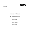
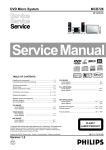
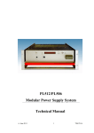
1
Notice
● CORRECTION
PRODUCTION CHANGE
SERVICE FLASH
ADD INFORMATION
FILE NO.
REVISION-1
Please add this notice to the Service Manual listed below.
Category :
Multi-media Projector
Model :
Destination :
PLV-Z4
U.S.A.,Canada,
Europe,Asia,Africa
Issued Date :
December / 2005
Effective from :
Chassis No. M4W-Z400
REF. NO. :
SM5110744
NOTE: Match the Chassis No. on the unit’s back cover with the Chassis No. in the Service
Manual.
If the Chassis No. does not match the unit’s, additional Service Literature is required.
Only the Difference Service Information is given in this manual. For detail Service
Information, Refer to the Original Service Manual SM5110744-00, issued in October
2005, for Model PLV-Z4.
Differences:
There are some miss-prints on the service manual SM5110744-00, see the next pages for correction.
FILE WITH ORIGINAL SERVICE MANUAL (SM5110744)
PRODUCT CODE
PLV-Z4 1 122 316 00
PLV-Z4 1 122 317 00
PLV-Z4 1 122 317 02
(M4WA)
(P4WA)
(P4WC)
REFERENCE NO. SM5110744-01
Contents / Mechanical Disassemblies
- NOTE Any information not contained in this manual will be found in the original model's service manual
SM5110744-00 for model PLV-Z4.
MAJOR CHANGES as below:
- Mechanical disassemblies
- Electrical adjustments
- Troubleshooting (No Power)
● On Page 22 about "Main power ass'y disassemblies-3"
Amend the following information;
7-4
- the screws-B for correction
Main power ass'y disassemblies-3.
1. Remove the 3 screws-A(M3x6) and remove the Power board.
2. Remove the 4 screws-B(T3x8), remove the Ballast unit and remove the Holder.
A
A
A
Power board
Holder
B
B
B
Ballast unit
B
Cover power bottom
Fig. 7-4
● On Pages from 23 to 25 about the order of mechanical disassemblies
Amend the following information;
- the order for correction
the order in the original service manual
8-1
8-2
9
10-1
10-2
the corrected order
Optical base lamp ass'y removal
Optical base lamp ass'y disassemblies
Lamp ass'y and filters removal
Lamp duct ass'y removal
Lamp cooling Fan(FN902) ass'y removal
8-1
8-2
9-1
9-2
10
-2-
Lamp duct ass'y removal
Lamp cooling Fan(FN902) ass'y removal
Optical base lamp ass'y removal
Optical base lamp ass'y disassemblies
Lamp ass'y and filters removal
Mechanical Disassemblies
● On Page 26 about "Filter board removal"
Amend the following information;
12
- the screw-C and the spacer sheet for correction
Filter board removal.
1.Remove the screw-C(T3x10) and remove the spacer sheet.
2.Remove the 4 screws-A(T3x8), remove the screw-B(M3x6) and remove the Filter board.
Spacer sheet
C
A
A
B
A
A
Filter board
Fig. 12
● On Page 27 about "Duct cover removal"
Amend the following information;
13
- the screw-A for correction
Duct cover removal.
1.Remove the screw-A(T3x8), remove the screw-B(M2x4), and remove the Duct cover.
B
Duct cover
A
Fig. 13
-3-
Mechanical Disassemblies
● On Page 38 about "Optical base top removal"
Amend the following information;
26
- the screws-A for correction
Optical base top removal.
1.Remove the 7 screws-A(T3x10) and remove the Optical base top.
A
A
A
A
A
A
the corrected screw
A
Optical base top
Fig. 26
-4-
Electrical Adjustments
● On Page 55 about "Iris adjustment"
Amend the following information;
- the iris adjustment method for correction
x Iris adjustment
Equipment
NIL
After replacing or repairing the LAMP IRIS, this readjustment is needed.
1. Enter the service mode.
2. Select group/item no. "105 - 14", and press the
"POINT RIGHT" button, then automatic iris adjustment will be done after about 30 sec. and the data
value will be changed from “0” to “1” automatically.
3. After this adjustment, change this data value from
“1” to “0” manually for normal operation.
● On Page 57 about "Optical base top removal"
Amend the following information;
- from 1 line dot pattern to 50% whole-white pattern for correction
n Common Center adjustment
Input mode
Image mode
Input signal
Computer [RGB(Analog)]
Powerful
50% whole-white pattern 720p computer signal
1. Enter the service mode.
2. Select group/item no. "4 - 114", and change data
value from “ 0 ” to “ 2 ”. (Flicker adjustment mode
...See Note)
3. Project only one color component to the screen.
4. Change data value to obtain the minimum flicker
for each color on the screen.
5. After this adjustment, select group/item no. "4 -114",
and change data value from “2” to “0” for normal
operation.(Or turn off the projector, then this data
value will be reset to “0” .)
Item no.
3-0
3-1
3-2
Screen
Only green color picture
Only blue color picture
Only red color picture
Note:
The FRP signal (common electrode reverse signal)
works at 120Hz, so flicker is invisible for human eyes.
The service mode "4 - 114" can change the FRP signal from 120Hz to 60Hz, and flicker can be seen.
-5-
Troubleshooting
● On Pages 80 and 81 about "No Power"
Amend the following information;
● No Power
- Troubleshooting description for correction
(with the underline)
This projector provides a function which can be specified a defective area simply by indicating the LEDs on the control panel. Connect the AC cord and turn the projector on and then check the LED indication.
Indicators
Troubleshooting
POWER
WARNING
red/green
red
No
Does a indicator flash
or light?
Yes
The primary power supply circuit
does not operate properly.
Yes
Is fuse (F601) broken?
No
Check SS5V power supply line.
-
POWER (red)
and WARNING
(red) indicators
are lighting?
When the main power switch is ON,
SS5V line is supplied to IC4801(Sub
CPU).
Yes
The symptom indicates that the projector detected an
abnormality in the cooling fan operation or in the power
supply secondary circuits. Check fan operation and power
supply lines, and the driving signal status.
-
Check following
items
An abnormality
occurs on the secondary power supply lines
An abnormality
occurs on the fan
control circuits.
An abnormality
occurs on power
starter signals.
POWER_FAIL (Error:L) signals are sent to IC301 via IC871
and IC1801, then IC301 shuts down the power supply circuit.
Check power supply lines, S5V,S-5V, S16V, etc. on the Main
board.
-
Refer to the diagram "Power Supply Lines".
Power failure detection diodes detect the fan operation stop.
Check FN901/902/903/904/905 and peripheral circuit.
Check connectors K8E/K8F from TH901/TH902.
-
Refer to the diagram "Fan control circuit".
Check power starter signals as follows:
-
-
To next page
Check Varistor (VA611).
Check Power Board.
-
PWR_SW signal (Power-on:H) is output from pin 12 of IC4801 and
sent to the Power Board and S16V, S16V_F, S6.5V, S5V, S-5V lines
are supplied.
MAINON_SW signal (Power-on:H) is output from pin 80 of IC301
and sent to the Power Board and lamp ballast 375V line is supplied.
5V_SW signal (Power-on:H) is output from pin 336 of IC301 and
sent to IC1581, IC8251, IC8281, Q4601, Q4603, then 12V, 3.3V_D,
3.3V_A, -5V, 6.5V lines are supplied.
3.3V_SW signal (Power-on:H) is output from pin 76 of IC301 and
sent to IC3601, then 3.3V, 1.2V lines are supplied.
15V_SW signal (Power-on:H) is output from pin 79 of IC301 and
sent to Q591, then 15.5V line is supplied.
FAN_SW signal (Power-on:H) is output from pin 81 of IC301 and
applied to the Fan power supply circuit.
-6-
Troubleshooting
yellow
LAMP
REPLACE
red
WARNING
Troubleshooting
From previous page
Cooling
WARNING (red) and
POWER (red) indicators are flashing?
The symptom indicates that the projector detected an
abnormal temperature risen inside the projector.
Check the air filters and remove the object near the
intake and exhaust fan openings, and wait until the
POWER indicator stops flashing, and then try to turn
on the projector.
- The internal temperature is monitored by the sensors,
Yes
IC8841 on Main Board, TH901 and TH902.
(Refer to "Fan control circuit")
Cooling
No
Cooling
POWER
red/green
/orange
Indicators
POWER (red) and
LAMP REPLACE
(yellow) indicators are
flashing?
The symptom indicates that the projector detected an
abnormality in the lamp driving signal. Check the
lamp driving signal, Lamp Cover SW and the
Thermal SW.
Yes
-
-
No
-
LAMP_SW signal (Lamp-on:L) from pin 16 of IC4801 is
sent to Lamp Ballast Unit through SW8803(Lamp Cover
SW) and SW902(Thermal SW).
TXL signal is output from pin 17 of IC4801 and sent to
Lamp ballast Unit via IC4833.
(TXL signal is applied for lamp power control. Lo: Low
power, Hi: High power)
RXL signal (Lamp status signal) is output from Lamp
Ballast Unit and sent to pin 18 of IC4801 via IC4833,
then LAMP_ERR signal is output from pin 4 of IC4801
and sent to IC301 via pin 7 of IC1801.
If an abnormality occurred on the lamp ballast unit, RXL
signal and LAMP_ERR signal become "H" and then the
projector will be cooled down and to stand-by mode
(POWER indicator lights red).
Lamp Cover Switch (SW8803 on Lamp SW board)
POWER indicator is
flashing orange?
Make sure that the lamp cover is mounted correctly. If
not or the lamp cover removed, the lamp does not light
on for the safety. Check the lamp cover and lamp cover
switch.
Yes
Thermal Switch (SW902) ......short in normal
SW902 opens when the surrounding temperature of the
switch exceeds 90°C.
Shutter Error at 3 cases;
(1) Error when turning on:
Flashing orange (continuation).
(2) Error when turning off:
Flashing red (60sec.),
flashing orange (60sec.),
and then lighting red.
(3) Error at normal mode:
Flashing red (60sec.) and
then lighting red.
• • • lights green.
• • • flashes green.
• • • flashes orange.
• • • flashes yellow.
The symptom indicates that the projector detected an
abnormality in the slide shutter. Check the slide shutter and the door switches.
Door Switches (SW8801/SW8811 on Door SW-A/B
board)
Make sure that the shutter is open or close. If it is halfopen or close, the lamp does not light.
• • • lights red.
-7-
• • • flashes red.
• • • off
(M4WA) Dec. 2005 BB 400 Printed in Japan
SANYO Electric Co., Ltd.