1
1979
UNIT REPAIR (OVERHAUL)
MANUAL
covering
CHEVROLET, MALIBU,
M O N TE CARLO, NOVA,
CAMARO
and
LIGHT DUTY TRUCKS
(SERIES 10-30)
FOREW ORD
T h is m an u al includes procedu res in volved in disassem bly and assem bly
o f m a jo r c o m p o n e n ts o f 1 9 7 9 C h e v ro le t, M a lib u , M o n te C a rlo , N o v a , C a m a ro
and L ig h t D u ty T ru c k s . In fo rm a tio n on diagnosis, m a in te n a n c e and a d ju s t
m ents, m in o r service o p e ra tio n s , and rem oval and in s ta lla tio n fo r these
c o m p o n e n ts is c o n ta in e d in e ith e r th e 1 9 7 9 Passenger C ar o r th e L ig h t D u ty
T r u c k S ervice M anuals.
T h e S e c tio n In d e x on th e c o n te n ts page enables th e user to q u ic k ly lo c a te
any desired s ectio n . A t th e beginning o f each section c o n ta in in g m o re th a n
one m a jo r subject is a T a b le o f C o n te n ts , w h ic h gives th e page n u m b e r on
w h ic h each m a jo r su bject begins. A n in d e x is placed a t th e b e ginning o f each
m a jo r su b ject w ith in th e s e ction.
S u m m a rie s o f S pecial T o o ls , w h e n re q u ire d , are fo u n d a t th e end o f m a jo r
sections.
W h en re fe re n c e is m ade in th is m an u al to a b rand n am e, n u m b e r, or specific
to o l, an e q u iv a le n t p ro d u c t m a y be used in place o f th e re c o m m e n d e d ite m .
T h e m an u al should be k e p t in a h a n d y place fo r re a d y re fe re n c e . If p ro p
e rly used, it w ill e n ab le th e te c h n ic ia n to b e tte r serve th e o w n e rs o f C h e v
ro le t b u ilt vehicles.
A ll in fo rm a tio n , illu s tra tio n s and s p e c ific a tio n s c o n ta in e d in this lite ra tu re
are based on th e latest p ro d u c t in fo rm a tio n availab le a t th e tim e o f p u b lic a
tio n a p p ro v a l. T h e rig h t is reserved to m a k e changes at a n y tim e w ith o u t
n o tic e .
IMPORTANT SAFETY NOTICE
P ro p er service and rep air is im p o rta n t to th e safe, reliable o p e ra tio n o f all
m o to r vehicles. T h e service p ro c ed u res re c o m m en d ed and described in this
service m an u al are effectiv e m e th o d s fo r p erfo rm in g service o p e ratio n s.
Som e o f these service o p e ra tio n s req u ire th e use o f to o ls specially designed
fo r th e p u rp o se. T he special to o ls sh o u ld be used w hen and as rec o m m en d ed .
It is im p o rta n t to n o te th a t this m anual co n tain s various C au tio n s and
N otices w hich sh o u ld be carefu lly read in o rd e r to m in im ize th e risk o f
p ersonal in ju ry to service p erso n n el or th e p o ssibility th a t im p ro p e r service
m e th o d s will be follo w ed w hich m ay dam age th e vehicle o r re n d e r it unsafe.
It also is im p o rta n t to u n d e rsta n d th a t these C au tio n s and N o tices are n o t
exhau stiv e. T he m a n u fa c tu re r co u ld n o t possibly k n o w , evalu ate and advise
th e service tra d e o f all conceivable w ays in w hich service m ig h t be d o n e
or o f th e possible h a za rd o u s conseq u en ces o f each w ay. C o n se q u e n tly ,
th e m a n u fa c tu re r has n o t u n d e rta k e n any such b ro a d ev alu atio n . A c co rd
ingly, a n y o n e w ho uses a service p ro ce d u re o r to o l w hich is n o t re c o m m e n d
ed m u st first satisfy h im se lf th o ro u g h ly th a t n e ith e r his safety n o r vehicle
safety will be je o p a rd iz e d by th e service m e th o d he selects.
SECTION INDEX
SECTION
1979
UNIT REPAIR (OVERHAUL)
M ANUAL
NAME
1D
AIR CONDITIONING
COMPRESSOR
3B
STEERING
4B
REAR AXLE
4C
FRONT WHEEL DRIVE
5
BRAKES
7A
AUTOMATIC TRANSMISSION
7B
MANUAL TRANSMISSION
7C
CLUTCH
7D
TRANSFER CASE
CAUTION
This vehicle contains so m e parts dim ensioned in the m etric system
a s well a s in the custom ary system. S o m e fasteners are metric and
are very d o s e in dim ension to familiar custom ary fasteners in the
inch system. It is im portant to note that, during any vehicle m ainte
n an ce procedures, replacem ent fasteners m u st have the sa m e
m easurem ents a n d strength a s those removed, whether m etric or
custom ary. (N um bers on the h eads of metric bolts a n d on surfaces
o f m etric n u ts indicate their strength. Custom ary bolts use radial
lines for this purpose, while m o st custom ary nuts do not have
strength m arkings.) M ism a tch e d or incorrect fasteners can result in
vehicle dam age or malfunction, or po ssib ly p e rso n al injury. There
fore, fasteners re m o ve d from the vehicle sh o u ld be s a v e d for re-use
in the sa m e locations w henever possible. Where the fasteners are
not satisfactory for re-use, care sh o u ld be taken to select a re
placem ent that m a tch e s the original. For information a n d a ssis
tance, see your Authorized dealer.
© 1979 G e n e r a l M o t o r s C o r p o r a tio n -
j
P rinted In U .S .A .
AIR C O N D IT IO N I N G C O M P R E S S O R O V E R H A U L ID -1
SECTIO N 1D
A IR C O N D IT IO N IN G C O M P R E S S O R
O VERH A U L
For Compressor REM OVAL A N D INSTALLATION , see Air
Conditioning Section. For D ISCH A RG IN G , A D D IN G OIL,
EV A CU A TIN G A N D C H A R G IN G PROCEDURES FO R C.C.O.T.
A /C SYSTEMS, see Air Conditioning Section.
CO NTENTS OF TH IS SECTIO N
M inor Repair Procedures for the A-6
Com pressor........................................................ .........
A-6 Compressor Clutch Plate and
H ub Assem bly.............................................. .........
A-6 Compressor Pulley and Bearing
Assembly........................................................ .........
..
A-6 Compressor Pulley Bearing...................
A-6 Compressor Clutch Coil and
Housing Assembly........................................ .........
M ajor A-6 Compressor Repair
P rocedures.......................................................... .........
A-6 Compressor Shaft Seal............................ .........
Seal Leak D etection.................................... .........
A-6 Compressor Pressure Relief
Valve or Pressure Sw itch........................... .........
A-6 Compressor Cylinder and Shaft
Assembly......................................................... .........
R em oval.......................................................... .........
D isassem bly................................................... ........
Gaging O peration......................................... .........
A-6 Teflon Piston Ring
Replacem ent.............................................. ........
Assembly......................................................... .........
Re-Install........................................................ .........
M inor Repair Procedures for the R-4
C om pressor........................................................ ........
R-4 Compressor Clutch Plate and
Hub A ssem bly.............................................. .........
R-4 Compressor Clutch Rotor
a n d /o r B earing............................................. .........
Replace R otor and Bearing
ID-2
ID-2
ID-5
ID-7
ID-7
ID-8
ID-9
ID-9
ID-11
ID-11
ID-12
ID-14
ID-15
ID-19
ID-19
ID-21
ID-26
ID-26
ID-26
For all practical purposes, all vehicles make use of the
same air conditioning 4 and 6-cylinder compressors. Actual
differences between compressors are found in their
mounting brackets, pulleys, connector assemblies and
compressor capacitires, none of which will affect the
following Overhaul Procedures.
When servicing the compressor, it is essential that steps
be taken to prevent dirt or foreign material from getting on
or into the compressor parts and system during disassembly
or reassembly of the compressor. CLEA N TOOLS AND
CLEA N W O RK A R EA A R E VERY IM PO RTA N T FOR
PRO PER SERVICE. The compressor connection areas and
Assembly (On C a r)................................ ...........
Replace Rotor and Bearing
Assembly (O n B e n c h ).......................... ...........
R-4 Compressor Clutch Coil
and/or Pulley R im .................................... ............
R-4 Compressor Inertia Ring
Installation................................................... ...........
Major R-4 Compressor Repair
Procedures....................................................... ...........
R-4 Compressor Shaft Seal.......................... ...........
Seal Leak D etection.................................. ...........
R-4 Compressor Shaft Seal
Replacement (O n C a r )......................... ...........
R-4 Compressor Shaft Seal
Replacement (O ff C a r )......................... ...........
R-4 Compressor Pressure Relief
Valve or Pressure Sw itch......................... ...........
R-4 Compressor Front Head
and/or O -Ring............................................ ...........
R-4 Compressor Thrust and
Belleville W ashers...................................... ...........
R-4 Compressor Main Bearing................... ...........
R-4 Compressor Shell and/or
O -R ings......................................................... ...........
R-4 Compressor Discharge Valve
Plate and/or R etain er............................... ...........
R-4 Compressor Cylinder and
Shaft Assembly........................................... ...........
A-6 and R-4 Comp. Leak Testing
(External and In te rn a l)............................ ...........
ID-30
ID-31
ID-32
ID-32
ID-34
ID-35
ID-35
ID-35
ID-37
ID-37
ID-37
ID-39
ID-39
ID-39
ID-41
ID-42
ID-42
exterior of the compressor should be cleaned off as much
as possible prior to any "on car" repairs or removal of the
compressor for workbench service. The parts must be kept
clean at all times and any parts to be reassembled should
be cleaned with
naphtha, Stoddard solvent,
kerosene or equivlent solvent and dried off with dry air.
When necessary to use a cloth on any part, it should be of
a non-lint producing type.
Although certain service operations can be performed
without completely removing the compressor from the
vehicle, the operations described herein are based on bench
over-haul with the compressor removed from the vehicle.
1 D-2 A IR C O N D IT IO N I N G C O M P R E S S O R O V E R H A U L
They have been prepared in sequence in order of
accessibility of the components. Pad fender/skirt and secure
compressor near top of fender skirt with wire, rope, etc.
when performing on-car service.
When an A -6 or R-4 compressor is removed from the
vehicle for servicing, the am ount of oil remaining in the
compressor should be drained and measured. This oil should
then be discarded and new 525 viscosity refrigerant oil
added to the compressor (See Figure ID-1, and "C.C.O.T.
Refrigerant Oil Distribution" in the Air Conditioning
section).
Should an A -6 compressor, its compressor shaft seal or
any other component ever be removed for servicing because
it was determined to be the cause of excessive signs of oil
leakage in the A /C system, then the oil in the A -6
compressor must be drained, measured and replaced
according to "C.C.O.T. Refrigerant Oil Distribution" in the
Air Conditioning section to determine oil loss. The
accumulator in this A -6 system then must also be removed
- oil drained - measured, etc. according to same section.
NOTICE: Do not kink or place excessive tension on
refrigerant lines or hoses.
M IN O R R E P A IR P R O C E D U R E S FOR
THE A-6 C O M P R E S S O R
THE FOLLOW ING OPERATIONS TO THE A-6
COMPRESSOR CLUTCH PLATE AND HUB, PULLEY
AND BEARING, AND COIL AND HOUSING ARE
COVERED AS "MINOR" BECAUSE THEY M A Y BE
PERFORMED W ITHO UT FIRST PURGING THE
SYSTEM OR REMOVING THE COMPRESSOR FROM
THE VEHICLE.
The Compressor Shaft Seal assembly, Pressure Relief
Valve and Pressure Switch may also be serviced W ITHOUT
REM O V IN G T H E COM PRESSOR from the vehicle but
these operations are covered later in this section as "Major
Repair Procedures" because the system MUST FIRST BE
PU R G ED of Refrigerant-12.
Illustrations used in describing these operations show
the compressor removed from the vehicle only to more
clearly illustrate the various operations.
When servicing the compressor, remove only the
necessary components that preliminary diagnosis indicates
are in need of service. Refer to the A IR C O N D IT IO N IN G
section and Figure ID -2 and Figure ID-3 for information
relative to parts nomenclature and location.
Removal and illustration of external compressor
components and disassembly and assembly of internal
components must be performed on a clean workbench. The
w ork area, tools, and parts must be kept clean at all
times. Parts Tray J-9402 (Figure ID -38) should be used for
all A -6 internal compressor parts being removed, as well as
for replacement parts.
A-6 C O M P R E S S O R CLU TCH PLATE
A N D HUB A S S E M B L Y
Figure 1D-1 A-6 Com pressor
2. Keep clutch hub from turning with Clutch Hub
Holder J-25030 or J-9403, and remove locknut from end of
shaft using Thin Wall Socket J-9399 (Figure ID -4).
NOTICE: To avoid internal damage to the compressor,
DO NOT D RIV E OR PO U N D on the Clutch Plate
and Hub assembly OR on the end of the shaft. If proper
tools to remove and replace clutch parts are not used,
it is possible to disturb the position of the axial plate
(keyed to the main shaft), resulting in compressor
damage and seal leakage due to shifting of the
crankshaft.
3. Thread Clutch Plate and Hub assembly Remover
J-9401 into hub. Hold body of Remover with a wrench and
tighten center screw to remove Clutch Plate and Hub
assembly (Figure ID -5).
4. Remove square drive key from shaft or drive plate
hub.
5. Remove hub spacer retainer ring using Snap-Ring
Pliers J-5403 ( # 2 1 ) , and then remove hub spacer (Figure
ID - 6).
6. Inspect driven plate for cracks or stresses in the drive
surface. Do not replace driven plate for a scoring condition
(Figure ID -7).
If the frictional surface shows signs of damage due
to excessive heat, the Clutch Plate, Hub, Pulley and
Bearing should be replaced. Check further for the
underlying cause of the damage (i.e. low coil-voltage - coil
should draw 3.2 amps at 12 volts - or binding of the
compressor internal mechanism (cylinder and shaft
assembly), clutch air gap too wide (see Figure ID -11),
broken drive plate to hub assembly sprints, etc.
Replace
1. Insert the square drive key into the hub of driven
plate; allow it to project approximately 3/16" out of the
Remove
keyway.
2. Line up the key in the hub with key way in the shaft
1.
Place Holding Fixture J-9396 in a vise and clamp the
(Figure ID - 8).
compressor in the Holding Fixture.
O-RING
FRONT H EAD
SHAFT SEA L A SSEM BLY
SEA L SEAT
I
/
O -R IN G S
j j C T iA
P R E S S U R E R E L IE F
/
R IN G
o
4?
I
/ /
S E A L S E A T R E T A IN E R R IN G
/
Tj J
^ 0
7
O -R IN G *
O -RIN G
SU C T IO N S C R E E N
/
A BSO RBEN T SLEEVE
S L E E V E R E T A IN E R
C L U T C H C O IL R E T A IN E R R IN G
1 /
Qk / /
C O M PRESSO R SH E LL
C L U T C H C O IL A N D H O U SIN G A S S E M B L Y
PULLEY
O IL
D R A IN PLU G
IN N E R O IL PUMP G E A R
B E A R IN G
O IL PIC K-U P T U B E
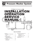
Figure
|
B E A R IN G R E T A IN E R
O -RING *
\
P U L L E Y R E T A IN E R R IN G
CLUTCH PLATE A N D
HUB A SSE M B L Y
/
O U T E R O IL PUMP C O V E R
R E A R D IS C H A R G E V A L V E PLAT E A S S E M B L Y
SH A FT
L O C K NU T
j
T E F L O N PIST O N R IN G
BALL
SH O E D IS C
COM PRESSOR
of A-6 Com pressor
R E A R SU C T IO N R E E D
B U S H IN G
N E E D L E B E A R IN G /
O -R IN G
R E A R C Y L IN D E R H A LF
T E F L O N R IN G T Y P E PIST O N
T E F L O N PIST O N R IN G
SHAFT
D IS C H A R G E C R O S S O V E R T U B E
TH RU ST RA CES
OVERHAUL
B U S H IN G *
FRONT
S U C T IO N R E E D
'D IS C H A R G E C R O S S O V E R T U B E O -R IN G OR B U S H IN G
AIR CO N D ITIO N IN G
1D-2 Exploded View
LOCK NUT
R EA R HEAD
F R O N T D IS C H A R G E
V A L V E PLATE A SSE M B L Y
4978
1D -3
1 D-4 A IR C O N D IT IO N I N G C O M P R E S S O R O V E R H A U L
SUCTIO N REED
TE FLO N PISTON R ING
SHELL)
FR O N T
DISCHARG E V A L V E PLATE
SH A FT SEAL ASM.
* PU LLEY
PU LLE Y B EA R IN G
CLUTCH PLATE
AND
HUB A SSEM BLY
REAR HEAD
O IL PUMP
GEARS
^ S E A L SEAT
R E TA IN E R RING
PRESSURE R ELIE F
VALVE
SEAL SLEEVE
O IL PICK-UP TUBE
REAR C Y L IN D E R
HALF
FR O N T C Y L IN D E R
H ALF
CLUTCH C O IL
TH R U ST B EARING
A N D HOUSING
4987
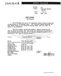
Figure 1D-3 A-6 Compressor Cross Section
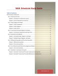
Figure 1D-4 Rem oving A-6 Shaft Lock Nut
Figure 1D-5 Removing A-6 Clutch Plate and
Hub Assembly
A IR C O N D IT IO N IN G C O M P R E S S O R O V E R H A U L 1D -5
Figure 1D-6 Removing or Installing Retainer Ring in A-6 Clutch
Drive Plate
Figure 1D-9 Installing A-6 Drive Plate
NOTICE: Make certain key remains in place when
pressing hub on shaft.
A ZERO thrust race is approximately 3/32" thick and
may be used to roughly gage this operation. Use Clutch Hub
Holder J-25030 or J-9403 to hold Clutch Plate and Hub if
necessary.
5. Install the hub spacer and, using Snap-Ring Pliers
J-5403 ( # 2 1 ) , install the retainer ring (see installed Retainer
Ring in Figure ID -10), with convex side of ring facing
spacer.
5038
Figure 1D-7 A-6 Clutch Driven Plate and Drive Plate
H O L D IN G FIX TU R E
6. Using Thin-Wall Socket J-9399 and Clutch Hub
Holder J-25030 or J-9403 to install a new shaft locknut w ith
shoulder or circular projection on the locknut facing
towards retainer ring. Tighten the nut to 14-26 lb.ft.
torque. Air gap between the frictional faces should now be
.022" to .057" (Figure ID -11). If not, check for
mispositioned key or shaft.
7. The pulley should now rotate freely.
8. Operate the refrigeration system in the MAX A /C
control selector (m ode) lever position and warm engine (off
fast idle) speed at 2000 PRM . Rapidly cycle the compressor
clutch by turning the A /C control selector (m ode) lever
from OFF-to-M AX at least 15 times at approximately one
second intervals to burnish the mating parts of the clutch.
A-6 C O M P R E S S O R PULLEY A N D
B E A R IN G A S S E M B L Y
Remove
Figure 1D-8 Aligning A-6 Drive Plate Key
3. Install the Drive Plate Installer J-9480-1 as
illustrated. This Installer has a left hand thread on the body
(Figure ID -9).
4. Press the driven plate onto the shaft until there is
approximately 3/32" space between the frictional faces of
the Clutch Drive Plate and Pulley.
1. Remove Clutch Plate and Hub assembly as described
in "A-6 Compressor Clutch Plate and Hub Assembly"
Removal procedure.
2. Remove pulley retainer ring, using Snap-Ring Pliers
J-6435 ( # 2 6 ) , Figure ID-12.
3. Pry out absorbent sleeve retainer, and remove
absorbent sleeve from compressor neck.
4. Place Puller Pilot J-9395 over end of compressor
shaft.
I D - 6 A IR C O N D IT IO N IN G C O M P R E S S O R O V E R H A U L
SHAFT SEAL ASM.
Figure 1D -12 Removing A-6 Pulley Retainer Ring
Pulley and Bearing asssembly should be cleaned with
naphtha, Stoddard solvent, kerosene or
equivalent solvent before reinstallation.
Replace
Figure 1D -10 Installing Hub Retainer Ring On A-6 Compressor
1. If original Pulley and Bearing assembly is to be
reinstalled, wipe frictional surface of pulley clean. If
frictional surface of pulley shows any indication of damage
due to overheating, the Pulley and Bearing assembly should
be replaced.
2. Check bearing for brineling, excessive looseness,
noise, and lubricant leakage. If any of these conditions exist,
bearing should be replaced. See "A-6 Compressor Pulley
Bearing" Replacement procedure.
PULLER
J-8433
Figure 1 D -1 1 Checking A-6 Air Gap
NOTICE: It is im portant that Puller Pilot J-9395 be
used to prevent internal damage to compressor when
removing pulley. Under no circumstances should
Puller be used D IRECTLY against drilled end of shaft.
PULLEY A N D
BEARING
A SSEM B LY
PULLER PILOT
J-9395
5066
Figure 1D -13 Removing A-6 Pulley and Bearing Assem bly
5.
Remove Pulley and Bearing Assembly, using Pulley
3.
Press or tap Pulley and Bearing assembly on neck
Puller J-8433 (Figure ID -13).
of compressor until it seats, using Pulley and Bearing
Installer J-9481 with Universal Handle J-8092 (Figure 1D14). The Installer will apply force to inner race of bearing
Inspection
and prevent damage to bearing.
Check the appearance of the Pulley and Bearing
assembly (see Figure ID -7). The frictional surfaces of the
A IR C O N D IT IO N IN G C O M P R E S S O R O V E R H A U L I D - 7
J-9398 with Universal Handle J-8092, drive Bearing
assembly out of pulley (Figure ID -16).
UNIVERSAL
HANDLE
J-8092
PULLEY A N D
BEARING
INSTALLER
J-9481
Figure 1D -14 Installing A-6 Pulley and Bearing Assembly
5039
4. Check pulley for binding or roughness. Pulley should
rotate freely.
5. Install retainer ring, using Snap Ring Pliers J-6435
(# 2 6 ).
6. Install absorbent sleeve retainer in neck of
compressor. Using sleeve from Seal Seat Remover-Installer
J-23128, install retainer so that outer edge is recessed 1/32"
from compressor neck face.
7. Install Clutch Plate and Hub assembly as described
in "A-6 Compressor Clutch Plate and Hub Assembly"
Replacement procedure.
A-6 C O M P R E S S O R PULLEY B E A R IN G
Remove
1. Remove Clutch Plate and Hub assembly as described
in "A-6 Compressor Clutch Plate and Hub Assembly"
Removal procedure.
2. Remove Pulley and Bearing assembly as described
in "A-6 Compressor Pulley and Bearing Assembly"
Removal procedure.
3. Remove pulley bearing retainer ring with a small
screwdriver or pointed tool (Figure ID -15).
BEARING
RETAINER
RING
Figure 1D -16 Rem oving Bearing From A-6 Pulley Assembly
Replace
1. Install new bearing in pulley using Pulley and
Bearing Installer J-9481 with Universal Handle J-8092
(Figure ID -17). The Installer will apply the force to the
outer race of the bearing.
NOTICE: DO NOT CLEAN NEW BEA RIN G
ASSEMBLY W ITH ANY TY PE OF SOLVENT.
Bearing is supplied with correct lubricant when
assembled and requires no other lubricant at any time.
2. Install bearing retainer ring, making certain that it
is properly seated in ring groove.
3. Install Pulley and Bearing assembly as described in
"A-6 Compressor Pulley and Bearing Assembly"
Replacement procedure.
4. Install Clutch Plate and Hub assembly as described
in "A-6 Compressor Clutch Plate and Hub Assembly"
Replacement procedure.
A-6 C O M P R E S S O R CLUTCH COIL A N D
H O U SIN G A S S E M B L Y
Remove
1. Remove Clutch Plate and Hub assembly as described
in "Compressor Clutch Plate and Hub Assembly" Removal
procedure.
2. Remove Pulley and Bearing assembly as described
in "A-6 Compressor Pulley and Bearing Assembly"
Removal procedure.
Figure 1D -15 Removing A-6 Pulley and Bearing Retainer Ring
4.
Place Pulley and Bearing assembly on inverted
Support Block J-21352 and, using Pulley Bearing Remover
NOTICE: Position of terminals on coil housing and
scribe location on compressor front head casting.
3.
Remove coil housing retaining ring, using Snap-Ring
Pliers J-6435 ( # 2 6 ) (Figure ID -18).
1 D-8 A IR C O N D IT IO N I N G C O M P R E S S O R O V E R H A U L
S N A P R IN G P LIE R S
J -6 4 3 5 ( # 2 6 )
CLUTCH COIL AND
HOUSING ASSEMBLY
TAINER
sIG
UNIVERSAL
HANDLE
J-8092
THIS RIDGE
OF TOOL
M U ST BE
UP WHEN
INSTALLING
BEARING
SUPPORT
BLOCK
J-21352
Figure 1D -18 Removing A-6 Coil Housing Retainer Ring
PULLEY AND
BEARING
INSTALLER
J- 9 4 8 1
4952
E L E C T R IC A L
T E R M IN A L S
Figure 1D -17 Installing Bearing on A-6 Pulley
4. Lift Coil and Housing assembly off compressor.
Replace
1. Position coil and housing assembly on compressor
front head casting so that electrical terminals line up with
marks previously scribed on compressor (Figure ID -19).
2. Align locating extrusions on coil housing with holes
in front head casting.
3. Install coil housing retainer ring w ith flat side of
ring facing coil, using Snap-Ring Pliers J-6435 ( # 2 6 ) .
4. Install Pulley and Bearing assembly as described in
"A-6 Compressor Pulley and Bearing Assembly"
Replacement procedure.
4959
Figure 1D -19 Installing A-6 Coil Housing
5. Install Clutch Plate and Hub assembly as described
in "A-6 Compressor Clutch Plate and Hub Assembly"
Replacement procedure.
M A J O R A-6 C O M P R E S S O R REPAIR P R O C ED U R ES
Service repair procedures to the Compressor Shaft Seal,
Pressure Relief Valve, Pressure Switch or disassembly of the
Internal Compressor Cylinder and Shaft Assembly are
considered "Major" since the refrigeration system must be
completely purged of refrigerant before proceeding and/or
because major internal operating and sealing components of
the compressor are being disassembled and serviced. Should
an A-6 compressor, it’s compressor shaft seal, or any other
component ever be removed for servicing because it was
determined to be the cause of excessive signs of oil leakage
in the A-6 A /C system, then the oil in the compressor must
be drained, measured and replaced according to "C.C.O.T.
Refrigerant Oil Distribution" in the Air Conditioning
section to determine oil loss. The accumulator in this A-6
system must then also be removed - oil drained - measured,
etc. according to same section.
When replacing the shaft seal assembly (see Figure 1D20), pressure relief valve (see Figure ID -26) or pressure
switch (see Figures ID -27 and 28), even if the compressor
remains on the vehicle during the operation, it will be
necessary to purge the system of refrigerant as outlined in
the Air conditioning section (see "Discharging, Adding Oil,
Evacuating and Charging Procedures for C.C.O.T. A /C
A IR C O N D IT IO N IN G C O M P R E S S O R O V E R H A U L 1D-9
Systems"). The same holds ture for any disassembly of the
internal A-6 compressor cylinder and shaft assembly.
If the A-6 Compressor Internal Cylinder and Shaft
Assembly is to be serviced or replaced, then the oil in the
compressor must be drained, measured and replaced
according to "C.C.O.T. Refrigerant Oil Distribution" in the
Air Conditioning section to determine addition of proper oil
quantity to new assembly.
A clean workbench, preferably covered with a sheet of
clean paper, orderliness in the work area and a place for all
parts being removed and replaced is of great importance, as
is the use of the proper, clean service tools. Any attempt to
use make-shift or inadequate equipment may result in
damage and /o r improper compressor operation.
These procedures are based on the use of the proper
service tools and the condition that an adequate stock of
service parts is available. All parts required for servicing the
internal compressor are protected by a preservation process
and packaged in a manner which will eliminate the necessity
of cleaning, washing or flushing of the parts. The parts can
be used in the internal assembly just as they are removed
from the service package.
Piston shoe discs and shaft thrust races will be
identified by "number" on the parts themselves for reference
to determine their size and dimension (see Figure ID -38).
Remove
1. "Discharge the Refrigerant System" according to the
DISCH A RG IN G , A D D IN G OIL, EVACUATING AND
CH A R G IN G PROCEDURES FO R C.C.O.T. A /C
SYSTEMS in the A IR C O N D ITIO N IN G section.
2. Remove the Clutch Plate and Hub assembly and
shaft key as described in "A-6 Compressor Clutch Plate and
Hub Assembly" Removal procedure.
3. Pry out the sleeve retainer and remove the absorbent
sleeve. Remove the shaft seal seat retaining ring, using SnapRing Pliers J-5403 ( # 2 1 ) . See Figure ID-21.
4. Thoroughly clean inside of compressor neck area
surrounding the shaft, the exposed portion of the seal seat
and the shaft itself. This is absolutely necessary to
prevent any dirt or foreign material from getting into
compressor.
5. Place Seal Protector J-22974 over the end of the shaft
to prevent chipping the ceramic seat. Fully engage the
knurled tangs of Seal Seat Remover-Installer J-23128 into
the recessed portion of the seal seat by turning the handle
clockwise. Remove the Seal Seat from the compressor with
a rotary-pulling motion (Figure ID -22). Discard the Seat.
A-6 C O M P R E S S O R SH A F T S EA L
S E A L LEAK DETECTION
A shaft seal should not be changed because of an oilline on the hood insulator. The Seal is designed to seep some
oil for lubrication purposes. Only change a Shaft Seal when
a leak is detected by evidence of oil sprayed in large amounts
and then only after actual refrigerant leakage is determined
by test.
Should an A-6 compressor shaft seal ever have to be
replaced because it was determined to be the cause of
excessive signs of oil leakage in the A /C system, then the
oil in the A-6 compressor must be drained, measured and
replaced according to "C.C.O.T. Refrigerant Oil
Distribution" in the Air Conditioning section to determine
oil loss. The accumulator in this A-6 system must then also
be removed - oil drained - measured, etc. according to same
section.
Figure 1D-21
Removing or Installing A-6 Shaft Seal Seat
Retaining Ring
NOTICE: DO NOT tighten the handle with a wrench
or pliers; however, the handle must be hand-tightened
securely to remove the seat.
S P E C IF IC A T IO N PA R TS
V eal
SEAT
f c a rb o n
m a te r ia l
L A R G E C H A M F E R ON
IN S ID E O IA M T E R .
I C E R A M IC M A T E R IA L
W IT H PO LIS H E D
FAC E.
O R IN G S j N EO P R E N E , T H U S
I C A P A B LE OF
G IV IN G H E A T
R E S IS T A N C E A N D
__________ | L IF E E X P E C T A N C Y .
0858
Figure 1D -20 Specification A-6 and R-4 Com pressor Shaft Seal
Kit
6. With Seal Protector J-22974 still over the end of the
shaft, seat Seal Remover-Installer J-9392 down over shaft
end, turning clockwise, while pressing down, to engage
remover tangs with the tabs on the Seal assembly. Then lift
the Shaft Seal assembly out (see Figure ID -23). Discard the
Seal.
7. Remove and discard the seal seat O-Ring from the
compressor neck, using O-Ring Remover J-9533 (see Figure
ID-22).
8. Recheck the shaft and inside of the compressor neck
for dirt or foreign material and be sure these areas are
perfectly clean before installing new parts.
1 D -1 0 A IR C O N D IT IO N IN G C O M P R E S S O R O V E R H A U L
Replace
Figure 1D -22 Removing A-6 Shaft Seal Seat and O-Ring
Figure 1D -23 Replacing A-6 Seal and O-Ring
Inspection
Seals should not be reused. Always use a new seal kit
on rebuild (see Figure ID -20). Be extremely careful that the
face of the Seal to be installed is not scratched or damaged
in any way. Make sure that the Seal Seat and Seal are free
of lint and dirt that could damage the seal surface or prevent
sealing.
1. Coat the new seal seat O-ring in clean 525 viscosity
referigerant oil and assemble onto O-Ring Installer J-21508
(see Figure ID -23).
2. Insert the O-Ring Installer J-21508 completely
down into the compressor neck until the installer
"bottoms". Lower the movable slide of the O-Ring Installer
to release the O-ring into the seal seat O-ring lower groove.
(The compressor neck top groove is for the shaft seal
retainer ring). Rotate the Installer to seat the O-ring and
remove Installer (See Figure ID -24).
3. Coat the O-ring and seal face of the new Seal
assembly with clean 525 viscosity refrigerant oil. Carefully
mount the Seal assembly to Seal Installer J-9392 by engaging
the tabs of the Seal with the tangs of the Installer (Figure
ID -23).
4. Place Seal Protector J-22974 (Figure ID -23) over
end of compressor shaft and carefully slide the new Seal
assembly down onto the shaft. Gently twist the Installer
J-9392 CLOCK-W ISE, while pushing the seal assembly
down the shaft until the Seal assembly engages the flats on
the shaft and is seated in place. Disengage the Installer by
pressing downward and twisting counter-clockwise.
5. Attach the ceramic Seal Seat to the Seal Seat
Remover and Installer J-23128 and dip the ceramic Seat in
clean 525 viscosity refrigerant oil to coat the seal face and
outer surface. Carefully install the Seat over the compressor
shaft end and Seal Protector J-22974 and push the Seat into
place with a rotary motion. Take care not to dislodge the
seat O-ring. However, be sure Seal Seat makes a good seal
with O-ring. Remove Installer J-23128 and Seal Protector
J-22974 (Figure ID -22).
6. Install the new seal seat retainer ring w ith its fla t
side against the Seal Seat, using Snap-Ring Pliers J-5403
( # 2 1 ) . See Figure ID-21. Use the sleeve from Seal Seat
Remover-Installer J-23128 (Figure ID -22) to press in on the
seal seat retainer ring so that it snaps into its groove.
7. Install Compressor Leak Test Fixture J-9625 (Figure
ID -25) on rear head of compressor and connect gage
charging lines or pressurize SUCTION SIDE (low-pressure
side) of compressor on vehicle with Refrigerant-12 vapor to
equalize pressure to the drum pressure. Temporarily install
the shaft nut and, with compressor in horizontal position
and oil sump down, rotate the compressor shaft in normal
direction of rotation several times by hand. Leak test the
Seal with Electronic Leak Detector J-23400. Correct any
leak found. Remove, discard and later replace the shaft nut.
8. Remove any excess oil, resulting from installing the
new seal parts, from the shaft and inside the compressor
neck.
9. Install the new absorbent sleeve by rolling the
material into a cylinder, overlapping the ends, and then
slipping the sleeve into the compressor neck with the overlap
towards the top of the compressor. With a small screwdriver
A IR C O N D IT IO N IN G C O M P R E S S O R O V E R H A U L 1D-11
shaft seal leaks may be the result of mispositioning of
the axial plate on the compressor s h a ft The
mispositioning of the axial plate may be caused by improper
procedures used during pulley and driven plate removal,
pounding, collisions or dropping the compressor. If the axial
plate is mispositioned, the carbon face of the shaft seal
assembly may not contact the seal seat and the rear thrust
races and bearing may be damaged.
To check for proper positioning of the axial plate on
the shaft, remove the clutch driven plate and measure the
distance between the front head extension and the flat
shoulder on the shaft as shown in Figure ID-24. To measure
this distance, use a wire gage (the clearance should be
between .026" and .075"). If the shaft has been pushed
back in the axial plate (measurement greater than .075"),
disassemble the compressor and replace the shaft and axial
plate assembly rear thrust races and thrust bearing.
If there also appears to be too much or insufficient air
gap between the drive and driven plates, dislocation of the
shaft should be suspected. If the carbon seal is not seating
against the seal seat, it will not be possible to completely
"Evacuate
the
System"
as
outlined
under
D ISCH A RG IN G , A D D IN G OIL, EVACUATING AN D
C H A R G IN G PRO CEDURES FO R C.C.O.T. A /C
SYSTEMS in the A IR C O N D IT IO N IN G section.
12.
"Add Oil, Evacuate and Charge System" (see
D ISC H A R G IN G , A D D IN G OIL, EVACUA TING A N D
C H A R G IN G PROCEDURES FO R C.C.O.T. A /C
SYSTEMS in the A IR C O N D IT IO N IN G section).
A-6 C O M P R E S S O R P R E S S U R E RELIEF
V A LV E OR P R E S S U R E S W IT C H
When necessary to replace the Pressure Relief Valve (or
Pressure Switch if so located), located in the compressor
rear head casting (Figure ID -26 and Figures ID -27 and 28),
the valve/switch assembly should be removed after
PU R G IN G TH E SYSTEM OF R EFR IG ER A N T. A new
valve/switch and O-ring coated with 525 viscosity
refrigerant oil should be installed (see D ISCH A RG IN G ,
A D D IN G OIL, EVA CU A TIN G A N D CH A R G IN G
PROCEDURES FO R C.C.O.T. A /C SYSTEMS in the
A IR C O N D ITIO N IN G section).
A-6 C O M P R E S S O R IN TER N A L
M E C H A N I S M (CYLIN D ER A N D SH AFT
ASSEM BLY)
Figure 1D -25 Leak Testing A-6 Com pressor
or similar instrument, carefully spread the sleeve until the
ends of the sleeve butt at the top vertical centerline.
10. Position the new metal sleeve retainer so that its
flange face will be against the front end of the sleeve. Pulley
Puller Pilot J-9395 (see Figure ID -13) may be used to install
the retainer. Press and tap with a mallet, setting the retainer
and sleeve into place (retainer should be recessed
approximately 1/32" from the face of the compressor neck).
(See Figure ID -24).
11. Reinstall the Clutch Plate and Hub assembly as
described in "A-6 Compressor Clutch Plate and Hub
Assembly" Replacement procedure. Some compressor
Service operations to the A-6 compressor Rear Head
or Internal Mechanism Cylinder and Shaft) of the
compressor should be performed with the system PU R G ED
OF R E FE R IG E R A N T according to the D ISC H A R G IN G ,
A D D IN G OIL, EV A CU A TIN G A N D C H A R G IN G
PROCEDURES FO R C.C.O.T. A /C SYSTEMS in the
A IR C O N D IT IO N IN G section. The compressor must also
be removed from the vehicle to insure that the necessary
degree of cleanliness may be maintained. Additionally,
"Compressor Clutch Plate and Hub, Pulley and Bearing,
Clutch Coil and Housing and Shaft Seal" Removal
procedures, as described earlier in the OVERHAUL
section, all are to have been followed. Clean hands, clean
tools and a clean bench, preferably covered with clean
paper, are of extreme importance.
1 D -1 2 A IR C O N D IT IO N I N G C O M P R E S S O R O V E R H A U L
2. All oil in compressor should be drained and
measured. Assist draining by positioning compressor with
oil drain plug down. Record the amount of oil drained
from the compressor (See "C.C.O.T. Refrigerant Oil
Distribution” in the AIR CO NDITIO NING section).
3. Invert compressor and Holding Fixture J-9396, with
front end of compressor shaft now facing downward (Figure
1-29).
DISCHARGE SYSTEM BEFORE
REMOVING HIGH PRESSURE
RELIEF VALVE
REAR HEAD
SHELL
5040
H O L D IN G
F IX T U R E
J -9 3 9 6
Figure 1D -26 A-6 High Pressure Relief Valve
0 R IN G
COMPRESSOR
PRESSURE S W ITCH
SNAP R IN G
Figure 1D -29 A-6 Com pressor Installed in Holding Fixture
6363
Figure 1D -27 Com pressor Pressure Switch
6364
Figure 1D -28 A-6 C om pressor Pressure Switch on A, B
An inspection should be made of the Internal
Mechanism (Cylinder and Shaft) assembly to determine if
any service operations should be performed. A detailed
inspection of parts should be made to determine if it is
feasible to replace them.
Additional oil may leak from the compressor at this
time. All oil must be drained into a container so that
TOTAL amount can be measured. (SEE STEP 2 ABOVE).
A liquid measuring cup may be used for this purpose.
Drained oil should then be discarded.
4. Remove four locknuts from threaded studs on
compressor shell and remove rear head. Tap uniformly
around rear head if head is binding (Figure ID -29).
5. Wipe excess oil from all sealing surfaces on rear head
casting webs, and examine sealing surfaces (Figure ID -30)
If any damage is observed, the Rear Head should be
replaced.
6. Remove Suction Screen and examine for any damage
or contamination. Clean or replace if necessary.
7. Paint an identifying mark on exposed face of innei
and outer Oil Pump Gears and then remove gears.
Identifying marks are to assure that gears, if re-used, will
be installed on identical position.
8. Remove and discard rear head to shell O-ring.
9. Carefully remove Rear Discharge Valve Plate
assembly. Use two small screwdrivers under reed retainers
to pry up on assembly (Figure ID-31). Do not position
screwdrivers between reeds and reed seats.
10. Examine Valve Reeds and Seats. Replace entire
assembly if any reeds or seats are damaged.
11. Using two small screwdrivers, carefully remove
Rear Suction Reed (Figure ID -32). Do not pry up on
horseshoe-shaped reed valves.
12. Examine reeds for damage, and replace if necessary,
13. Using Oil Pick-Up Tube Remove J-5139 (Figure
1.
Before proceeding with disassembly, wipe exterior ID -33), remove Oil Pick-Up Tube. Remove O-ring from oil
inlet.
surface of compressor clean.
Removal
A IR C O N D IT IO N IN G C O M P R E S S O R O V E R H A U L 1 D -1 3
Figure 1D -32 Removing A-6 Rear Scution Reed
REAR HEAD
SEALING
SU R FA C ES
SHELL TO HEAD
" 0 " RING
O I L P IC K - U P T U B E
R E M O V E R J -5139
O I L P IC K - U P T U B E
OIL PUMP
ROTORS
5042
Figure 1D -30 A-6 Rear Head Removal
Figure 1D -33 Removing A-6 Oil Pick-Up Tube
NOTICE: To prevent damage to shaft, DO NOT TAP
ON EN D O F COMPRESSOR SHAFT to remove
Internal Cylinder and Shaft Assembly. If Internal
Assembly will not slide out of compressor shell, tap on
Front Head with a plastic hammer.
16. Rest compressor shell on its side and push Front
Head assembly through Compressor Sheel, being careful
not to damage sealing areas on inner side of front head.
Discard O-ring. It may be necessary to tap on outside of
front head, using a plastic hammer, to overcome friction of
O-ring seal between front head and compressor shell.
17. Wipe excess oil from sealing surfaces on front head
casting webs and examine sealing surface. If any surface
damage is observed, the head should be replaced.
Figure 1D-31 Removing A-6 Rear Discharge Valve Plate
18. Remove Front Discharge Valve Plate assembly and
Front Suction Reed Plate. Examine reeds and seats. Replace
14.
Loosen compressor from Holding Fixture J-9396, necessary parts.
place Internal Cylinder and Shaft Assembly Support Block
J-21352 over oil pump end of shaft and, while holding
19. Remove Suction Cross-Over Cover by prying with
Support Block in position with one hand, lift compressor
screwdriver between cylinder casting and cover (Figure 1Dfrom Holding Fixture with other hand. Invert compressor
34).
(shaft will now be facing upw ard) and position on bench
with Internal Assembly Support Block resting on bench.
20. Examine Internal Cylinder and Shaft Assembly for
any obvious damage. If Internal Assembly has sustained
major damage, due to loss of refrigerant or oil, it may be
15.
Lift Front Head and Compressor Shell Assembly necessary to use the Service Internal Cylinder and Shaft
up, leaving Internal Cylinder and Shaft Assembly resting on
Assembly rather than replace individual parts.
Internal Assembly Support Block.
1 D -1 4 A IR C O N D IT IO N I N G C O M P R E S S O R O V E R H A U L
Figure 1D -36 S eparating A-6 Cylinder Halves
Figure 1D -34 Removing A-6 Suction Cross-Over Cover
A-6 C O M P R E S S O R IN TERNAL
C Y L IN D E R A N D SH A F T A S S E M B L Y
NOTICE: U N D ER NO CIRCUM STANCE SHOULD
SHAFT BE STRUCK AT EITH ER END in an effort
to separate upper and lower cylinder halves because the
shaft and the axial plate could be damaged.
4. Carefully remove the rear half of the cylinder from
the pistons and set the front cylinder half, with the piston,
Use Parts Tray J-9402 (Figure ID -38) to retain
shaft and axial plate in Compressing Fixture J-9397.
compressor parts during disassembly.
5. Pull up on compressor shaft and remove piston
1. Remove Internal Cylinder and Shaft Assembly from
previously identified as No. 1, with balls and shoe discs,
compressor as described in "A-6 Compressor Internal
from axial plate, a. Inspect the Teflon piston rings for
Mechanism (Cylinder and Shaft Assembly)” Removal
nicks, cuts or metal particles imbedded in exposed ring
procedure.
surface and replace the piston rings as required if either
2. Identify by pencil mark, or some other suitable
condition exists. See "A-6 Teflon Piston Ring" Replacement
means, each piston numbering them as 1, 2 and 3 (Figure
procedure.
ID -35).
6. Remove and discard the piston shoe discs.
7. Remove and examine piston balls, and if satisfactory
for re-use, place balls in No. 1 compartment of Parts Tray
J-9402 (Figure ID -38).
8. Place piston in No. 1 compartment of Parts Tray
J-9402, w ith notch in casting w eb at front end of piston
(Figure 1D-37) into the dimpled groove of Parts Tray
FRONT
compartment.
C Y L IN D E R
9. Repeat Steps 5 through 9 for Pistons No. 2 and No.
HALF
3.
10. Remove rear combination of thrust races and thrust
P IS T O N
bearing from shaft. Discard races and bearing.
11. Remove shaft assembly from front cylinder half. If
the Discharge Cross-Over Tube remained in the front
cylinder half, it may be necessary to bend discharge cross
SUPPORT
over tube slightly in order to remove shaft.
B L O C K J-21
12. Remove front combination of thrust races and
bearing from shaft. Discard races and bearing (Fig. ID -39).
13. Examine surface of Axial Plate and Shaft. Replace
Figure ID -3 5 Num bering A-6 Piston and Cylinder Bores
as an assembly, if necessary.
A certain am ount of shoe disc wear on axial plate is
Number the piston bores in the front cylinder half in
normal, as well as some markings indicating load of needle
like manner, so that pistons can be replaced in their original
bearings on shaft.
locations.
14. Remove Discharge Cross-Over Tube from cylinder
3.
Separate cylinder halves, using a wood block and
half, using self-clamping pliers. This is necessary only on
mallet (Figure ID -36). Make certain that discharge cross
original factory equipm ent as ends ofthe tube are
over tube does not contact axial plate when separating
swedged into cylinder halves. The discharge cross-over tube
cylinder halves (a new Service Discharge Cross-Over Tube
in Internal Cylinder and Shaft Assemblies that have been
will be installed later - see Step 5 of Internal Cylinder and
previously serviced have an O-ring and bushing at EACH
Shaft Assembly procedure).
Disassembly
A IR C O N D IT IO N IN G C O M P R E S S O R O V E R H A U L 1 D -1 5
16.
Needle bearings may be removed if necessary by
driving them out with special Thin-Wall Socket J-9399.
Insert socket in hub end (inner side) of cylinder head and
drive bearing out.
To install needle bearing, place cylinder half on Support
Block J-21352, and insert bearing in end of cylinder head
with bearing identification marks UP. Use Needle Bearing
Installer J-9432 and drive bearing into cylinder head (Figure
ID -40), until Installer "bottoms" on the cylinder face.
Two different width needle bearings are used in
Production compressors - a 1/2” size and a 5/8” size. The
bearings are interchangeable. Service replacement bearings
are all 1/2”.
Figure 1D -37 Notch Identifying Front End of A-6 Piston
N EEDLE B E A R IN G
IN S T A L L E R J -9432
NEEDLE B E A R IN G
C Y LIN D E R
HEAD
SUPPORT
B LO C K J-2 1 3 5 2
4975
Figure 1D -40 Installing A-6 Needle Bearing
17.
Wash all parts to be re-used with
naphtha, stoddard solvent, kerosene, or a similar solvent.
Air-dry parts using a source of clean, dry air. A-6
compressor internal components may be identified by
referring to Figure ID-2 and Figure ID-3.
T H R U S T RACE
A-6 C O M P R E S S O R IN TERNA L
C Y LIN D E R A N D SH A F T A S S E M B L Y
THRUST
S U P P O R T B LO C K
J -2 1 3 5 2
Gaging Operation
1.
Install Compressing Fixture J-9397 on Holding
Fixture J-9396 in vise. PLACE FRO N T CYLINDER
H A LF in Compressing Fixture, flat-side down. Front
cylinder half has long slot extending out from shaft
hole. "Legs" of front cylinder half will be pointed upward.
2.
Secure from Service parts stock four ZERO thrust
races, two thrust bearings and three ZERO shoe discs.
3. Now install a ZERO THRUST RACE, then one
thrust bearing, and a SECOND ZERO THRUST RACE
Figure 1D -39 Removing A-6 Front Thrust Races and Bearings
ONTO FRO N T EN D of compressor shaft. Lubricate races
and bearing with petrolatum.
EN D of the tube, and can be easily removed by hand (see
4. Insert threaded end of axial shaft through needle
Figure ID -58).
bearing in front cylinder half, and allow thrust race and
15.
Examine piston bores and needle bearings in front bearing assembly (race-bearing-race) to rest on hub of
cylinder.
and rear cylinder halves. Replace Front and Rear Cylinder
Halves. Replace front and rear cylinders if any cylinder bore
5. Now install a ZERO THRUST RACE ON REAR
is deeply scored or damaged.
END of compressor axial shaft (Figure ID -41), so that it
1 D -1 6 A IR C O N D IT IO N IN G C O M P R E S S O R O V E R H A U L
rests on hub of axial plate. Then add one thrust bearing and
a SECOND ZERO THRUST RACE onto shaft. Lubricate
races and bearing with petrolatum. At this point, BOTH
front end and rear end of axial shaft will have a stack-up
of one ZERO race-one bearing-one ZERO race.
THRUST BEARING
RACE
THRUST RACE
COMPRESSING
FIXTURE
J-9397
HOLDING FIXTURE
J-9396
FRONT
CYLINDER
HALF
Figure 1D -42 Installing A-6 Front Shoe Disc
REAR NEEDLE
THRUST BEARING
AND "ZERO” THRUST
RACES
Figure 1D-41 Installing A-6 Rear Thrust Races and Bearings
PISTON DRIVE
BALL ONLY
AT REAR
6. Lubricate ball pockets of the No. 1 Piston with 525
viscosity refrigerant oil and place a ball in each socket. Use
balls previously removed if they were considered acceptable
for re-use.
7. Lubricate cavity of a ZERO SHOE disc with 525
viscosity refrigerant oil and place shoe disc OVER BALL
IN FRO N T EN D of piston (Figure ID -42). Front end of
piston has an identifying notch in casting web (Figure
ID -37).
NOTICE: Exercise care in handling the Piston and
Ring Assembly, particularly during assembly into and
removal from the cylinder bores to prevent damage to
the Teflon piston rings.
SHOE DISCS SHOULD NOT BE INSTALLED ON
REAR of piston during following "Gaging" operation.
8. Rotate shaft and axial plate until high point of axial
plate is over the No. 1 Piston cylinder bore.
9. Lift the axial shaft assembly up a little out of front
cylinder half and hold front thrust race and bearing
assembly ("zero" race-bearing-"zero" race) against axial
plate hub.
10. Position No. 1 Piston over No. 1 cylinder bore
(notched end of piston being on bottom and piston
straddling axial plate) and lower the shaft to allow No. 1
Piston to drop into its bore (Figure ID -43).
11. Repeat Steps 6 through 10 for Pistons No. 2 and
No. 3.
12. NOW INSTALL R EA R C Y LIN D ER H A LF
ONTO PISTONS, aligning cylinder with discharge cross
over tube hole in front cylinder half. Tap into place using
a plastic mallet or piece of clean wood and hammer (Figure
ID -44).
r
FRONT CYLINDER
PISTON DRIVE
BALL AND
''ZERO” SHOE
DISC AT FRONT
Figure 1D -43 Installing A-6 Piston During Gaging Operation
13. Position discharge cross-over tube opening between
a pair of Compressing Fixture J-9397 bolts to permit access
for feeler gage.
14. Install top plate on Compressing Fixture J-9397.
Tighten nuts to 15 lb. ft. (20 N *m ) torque using a 0-25 lb.
ft. (0-60 N *m ) torque wrench.
Gaging Procedure (Steps 15 thru 18)
The gaging operations which follow have been worked
out on a simple basis to establish and provide necessary
running tolerances. Two gaging procedures are necessary.
The first is made to choose the proper size shoe discs
to provide, at each piston, a .0016" to .0024" total preload
between the seats and the axial plate at the tightest place
through the 360-degree rotation of the axial plate. The
bronze shoe discs are provided in .0005" variations,
including a basic ZERO shoe.
The second, performed at the rear shaft thrust race
and bearing stack-up, is designed to obtain .0025” to
.0030” preload between the hub surfaces of the axial
plate and the front and rear hubs of the cylinder. A total
A IR C O N D IT IO N IN G C O M P R E S S O R O V E R H A U L 1 D -1 7
4963
Figure 1D -44 Assem bling A-6 Cylinder Halves
of 14 steel thrust races, including a basic ZERO race, are
provided in increments of .0005" thickness to provide the
required fit.
Feeler and Tension Gage Set J-9564-01 or J-9661-01
may be used for gaging proper shoe disc size. Feeler Gage
Set J-9564-01 or Dial Indicator Set J-8001 may be used to
determine proper thrust race size.
PR O PER SELECTION O F THRUST RACES A N D
BALL SEATS IS OF EX TREM E IM PORTANCE.
15. Measure clearance between REA R BALL of No.
1 Piston A N D A X IA L PLATE, in following manner:
a. Select a suitable combination of well-oiled Feeler
Gage leaves to fit snugly between ball and axial plate.
b. A ttach Tension Gage J-9661-3 to the feeler gage. A
distribution point checking scale or Spring Scale J-544 may
be used.
c. Pull on Spring Scale to slide Feeler Gage stock out
from between ball and axial plate, and note reading on
Spring Scale as Feeler Gage is removed (Figure ID -45).
Reading should be between 4 and 8 ounces.
d. If reading in Step “ c” above is under 4 or over 8
ounces, reduce or increase thickness of Feeler Gage leaves
and repeat Steps a. through c. above until a reading of 4 to
8 ounces is obtained. Record the clearance between ball and
axial plate that results in the desired 4 to 8 ounce pull on
Spring Scale.
16. Now rotate shaft 120° and repeat Step 15 between
this same No. 1 Piston Rear Ball and axial plate. Record
this measurement.
If shaft is hard to rotate, install shaft nut onto shaft and
turn shaft with wrench.
Figure 1D -45 Gaging A-6 Rear Piston Ball
17. Rotate shaft another 120° and again repeat Step 15
between these same parts and record measurements.
18. Select a "NUM BERED" SHOE disc corresponding
to minimum feeler gage reading recorded in the three
checks just made above. (See example in Figure ID -47).
Place the selected shoe discs in Parts Tray J-9402
compartment corresponding to Piston No. 1 and rear ball
pocket position.
Shoe discs are provided in .0005" (one-half
thousandths) variations. There are a total of 11 sizes
available for field servicing. All shoe discs are marked wtih
the shoe size, which corresponds to the last three digits of
the piece part number. (See Shoe Disc Size Chart in Figure
ID -46).
Once a proper selection of the shoe has been made, the
matched combination of shoe disc to rear ball and spherical
cavity in piston must be kept in proper relationship during
disassembly after Gaging operation, and during final
assembly into the internal Cylinder and Shaft Assembly.
19. Repeat in detail the same Gaging Procedure
outlined in Steps 15 through 18 for Piston No. 2 and No.
3.
20A. Mount Dial Indicator J-8001 on edge of
Compressing Fixture J-9397 with Clamp J-8001-1 and
Sleeve J-8001-2 (Figure ID -48). Position Dial Indicator on
rear end of axial shaft and adjust to "zero".
From bottom, apply full hand-force at end of shaft a
few times before reading clearance. This will help squeeze
the oil out from/between mating parts. Now push upward
again and record measurement. Dial Indicator increments
are .001"; therefore, reading must be estimated to nearest
.0005".
1 D -1 8 A IR C O N D IT IO N I N G C O M P R E S S O R O V E R H A U L
THRUST BEA RIN G RACE
SHOE DISC
PART NO.
END ING IN
ID EN TIF IC A T IO N
STAMP
M IN .F E E L E R
G AGE R EA D IN G
PART NO.
ENDING IN
ID EN T IF IC A T IO N
STAMP
D IA L IN DICA TO R
R EA D IN G
000
175
180
185
190
195
200
205
210
215
220
0
17-1/2
18
18-1/2
19
19-1/2
20
20-1/2
21
21-1/2
22
.0000
.0175
.0180
.0185
.0190
.0195
.0200
.0205
.0210
.0215
.0220
000
050
055
060
065
070
075
080
085
090
095
100
105
110
115
120
0
5
5-1/2
6
6-1/2
7
7-1/2
8
8-1/2
9
9-1/2
10
10-1/2
11
11-1/2
12
.0000
.0050
.0055
.0060
.0065
.0070
.0075
.0080
.0085
.0090
.0095
.0100
.0105
.0110
.0115
.0120
09 13
Figure 1D -46 Available A-6 Service Shoes and Thrust Races
POSITION
1
POSITION
2
POSITION
3
SELECT
AN D USE
SHOE NO.
PISTON NO. 1
.019”
.0195"
.019"
19
PISTON NO. 2
.020"
.020"
.020"
20
PISTON NO. 3
.021"
.021"
.022"
21
D IA L IN D IC A T O R
J -8 0 0 1 -3
SLEEVE
J -8 0 0 1 -2
CLAMP
J -8 0 0 1 -1
0914
Figure 1D -47 Selection of Proper A-6 Shoe Disc
20B. An alternate method of selecting a proper race is
to use Gage Set J-9661-01 selecting a suitable feeler gage leaf
until the result is a 4 to 8 ounce pull on the scale between
the rear thrust bearing and upper (which also happens to
be the outer rear) thrust race (Fig. ID -49). If the pull is just
less than 4 ounces, add .0005" to the thickness of the feeler
stock used to measure the clearance. If the pull on the scale
reads just over 8 ounces, then subtract .0005" from the
thickness of the feeler stock.
21. For either method used, select a thrust race with
a "number" corresponding to TW O (2 ) FU LL SIZES
LA R G E R than Dial Indicator or Feeler Gage measurement
of the amount of end play shown. (I f measurement is .007",
select a No. 9 or 090 race.)
Place thrust race in right-hand slot at bottom center of
parts tray J-9402.
Fifteen (1 5 ) thrust races are provided in increments of
.0005" (one-half thousandths) thickness and one ZERO
gage thickness, providing a total of 16 sizes available for
field service. The thrust race "number" also corresponds to
the last three digits of the piece part number. See Thrust
Race Size Chart in Figure ID-46.
22. Remove nuts from top plate of compressing fixture
J-9397, and remove top plate.
23. Separate cylinder halves while unit is in fixture. It
may be necessary to use a wooden block and mallet.
24. Remove rear cylinder half and carefully remove one
piston at a time from axial plate and front cylinder half. Do
not lose the relationship of the front ball and shoe disc and
rear ball. Transfer each piston, ball and shoe disc to its
proper place in Parts Tray J-9402.
Figure 1D -48 Gaging A-6 Rear Thrust Race
25. Now remove rear outer zero thrust race (it will be
on top) from shaft and install the thrust race just selected
in Steps 20 and 21 that is presently setting in the right-hand
slot at bottom center of parts tray J-9402.
CHECKING FOR
REAR
THRUST
AND RACE
THICKNESS
FRONT THRUST
GIVES PROPER
HEAD CLEARANCE
CHECKING FOR SHOE
THICKNESS “X”
4980
Figure 1D -49 Checking A-6 Piston and Shaft End Play
A IR C O N D IT IO N IN G C O M P R E S S O R O V E R H A U L 1 D -1 9
The removed ZERO thrust race may be put aside for
re-use in additional Gaging or rebuilding operations.
26. Repeat for each piston.
A-6 C O M P R E S S O R C Y L IN D E R A N D
SH A F T A S S E M B L Y
A-6 Teflon Piston Ring Replacement
The Teflon piston ring installing, sizing and gaging
tools are shown in Figure ID-50.
1. Remove the old piston rings by CAREFULLY
slicing through the ring with a knife or sharp instrument,
holding the blade almost flat with the piston surface. Be
careful not to damage the aluminum piston or piston
groove in cutting to remove the ring.
C A U T IO N : Exercise personal care
cutting the piston ring for removal.
in
2. Clean the piston and piston ring grooves with
naphtha, Stoddard solvent, kerosene or
equivalent solvent and blow the piston dry with dry air.
3. Set the piston on-end on a clean, flat surface and
install the Ring Installer Guide J-24608-2 on the end of the
piston (Figure ID -51).
4. Install a Teflon ring on the Ring Installer Guide
J-24605-2 as shown in Figure ID -51, w ith the dished or
dullside down and glossy-side up.
5. Push the Ring Installer J-24608-5 down over the
Installer Guide J-24608-2 to install the Teflon ring in the
piston ring groove (Figure ID -52). If the Teflon ring is
slightly off position in the ring groove, it can be positioned
into place by fingernail or blunt-edged tool that will not
damage the piston.
The Ring Installer J-24608-5 will retain the Installer
Guide J-24608-2 internally when the Teflon ring is installed
on the piston. Remove the Installer Guide from the Ring
Installer and do not store the Installer Guide in the Ring
Installer, as the Ring Installer Segment Retainer O-Ring
J-24608-3 will be stretched and possibly weakened during
storage. This could result in the O-Ring J-24608-3 not
holding the Ring Installer segments tight enough to the
Installer Guide J-24608-2 to properly install the Teflon ring
on the piston.
6. Lubricate the piston ring area with 525 viscosity
refrigerant oil and rotate the Piston and Ring Assembly into
the Ring Sizer J-24608-6 at a slight angle (Figure ID-53).
R otate the piston, while pushing inward, until the piston is
inserted against the center stop of the Ring Sizer J-23608-6.
NOTICE: DO NOT push the Piston and Ring
Assembly into the Ring Sizer J-24608-6 without proper
positioning and rotating as described above, as the ends
of the needle bearings of the Ring Sizer may damage
the end of the piston.
7. Rotate the Piston and Ring Assembly in the Ring
Sizer J-24608-6 several CO M PLETE turns, until the
Assembly rotates relatively free in the Ring Sizer (Figure
ID-53).
8.
Remove the Piston and Ring Assembly, wipe the
end of the piston and ring area with a clean cloth and then
push the Piston and Ring Assembly into the Ring Gage
J-24608-1 (Figure ID -54). The piston should go through the
Ring Gage with a 6-lb. force or less without lubrication. If
not, repeat Steps 6 and 7.
9. Repeat the procedure for the opposite end of the
piston (Figure ID-55).
NOTICE: DO NOT lay the piston down on a dirty
surface where dirt or metal chips might come into
contact and become imbedded in the Teflon ring
surface.
10. Lubricate BOTH ENDS of the piston with 525
viscosity refrigerant oil before inserting the piston into the
cylinder bore.
NOTICE: Reasonable care should be exercised in
installing the piston into the cylinder bore to prevent
damage to the Teflon ring.
A-6 C O M P R E S S O R IN TER N A L
C Y LIN D E R A N D SH A F T A S S E M B L Y
Assembly
After properly performing the "Gaging Procedure",
choosing the correct shoe discs and thrust races, and
installing any needed Teflon piston rings, the cylinder
assembly may now be reassembled. Be sure to install all
NEW seals and O-rings. All are included in the compressor
O-Ring Service Kit.
Assembly procedure is as follows: 1. Support the
FRONT half of the cylinder assembly on Compressing
Fixture J-9397. Install the shaft and axial plate, threaded
end down, with its front bearing race pack (ZERO racebearing-NUM BERED race), if this was not already done
at the end of the "Gaging Procedure".
2. Apply a light smear of petroleum jelly to the
"numbered" shoe discs chosen in the Gaging Procedure and
install all balls and shoe discs in their proper place in the
piston assembly.
3. Rotate the axial plate so that the high point is above
cylinder bore No. 1.
a. Carefully assemble Piston No. 1, complete with
BALL A N D "ZERO" SHOE DISC ON TH E FRONT and
BALL A N D "NUM BERED" SHOE DISC ON TH E
REAR over the axial plate.
b. Hold front thrust bearing pack tightly against axial
plate hub while lifting hub.
c. Insert the Piston Assembly into the Front Cylinder
Half (Figure ID -56).
4. Repeat this operation for Pistons No. 2 and No. 3
(Figure ID -57).
5. W ithout installing any O-rings or bushings, assemble
one end of the new Service Discharge Cross-Over Tube into
the hole in the front cylinder half (Figure ID -58 and ID -59).
Be sure the flattened protion of this tube faces the
inside of the compressor to allow for axial plate clearance
(Figure ID-59).
Cylinder Half
6. Now rotate the shaft to position the pistons in a
stair-step arrangement; then carefully place the Rear
1 D -2 0 A IR C O N D IT IO N IN G C O M P R E S S O R O V E R H A U L
J -2 4 6 0 8 -2
R IN G IN S T A L L E R
G U ID E
J -2 4 6 0 8 -b
R IN G S IZ IN G T O O L
J -2 4 6 0 8 -1
P IS T O N R IN G G A G E
J -2 4 6 0 8 3 O -R IN G
Figure 1D -50 A-6 Teflon Piston Ring Installing, Sizing and Gaging Tools
T E F L O N PISTON RING
*
J-24608-5
RING INSTALLER
i
J - 2 4 6 0 8 - 2 RING
IN STA LLER
GUIDE
TEFLON RING
4984
Figure 1D -5 1 A-6 Teflon Piston Ring Positioned on Ring Installer
Guide
Figure 1D -52 Installing A-6 Teflon Piston Ring
8.
When all parts are in proper alignment, tap with a
clean wooden block and mallet to seat the rear half of the
7.
When all three Piston and Ring assemblies are in cylinder over the locating dowel pins. If necessary, clamp
the cylinder in Compressing Fixture J-9397, to complete
their respective cylinders, align the end of the discharge
drawing the cylinder halves together.
cross-over tube with the hole in the rear half of the cylinder.
Cylinder H alf over the shaft and start the pistons into the
cylinder bore (Figure ID-60).
A IR C O N D IT IO N IN G C O M P R E S S O R O V E R H A U L 1D-21
" S E L E C T E D " R E A R SH O E D IS C
PISTON AND
RING A SSEM B LY
"SELEC TED "
R E A R T H R U S T RA C E
BEARING
"Z E R O " FR O N T
SH O E D ISC
RO" THRUST
R A C E S L IF T
S H A FT UPW ARD
A N D HO LD THE
T H R U S T R A C ES
A N D B E A R IN G
A G A IN S T H U B
J-24608-6 RING
SIZING TOOL
4985
Figure 1D -53 Turning A-6 Piston and Ring Assembly Into Ring
Sizing Tool
T H R U S T B E A R IN G
09 20
Figure 1D -56 Installing 1st A-6 Piston Assembly Into Front
P IS T O N A N D R IN G A S S E M B L Y
N O T C H E D E N D ------- ^
4986
Figure 1D-54 Gaging A-6 Piston Ring Size
Figure 1D -57 Installing 2nd A-6 Piston
A-6 C O M P R E S S O R IN TERNA L
C Y LIN D E R A N D SH A F T A S S E M B L Y
Figure 1D -55 A-6 Teflon Piston Ring Installed in Piston
Re-Install
9. Generously lubricate all moving parts with clean 525
viscosity refrigerant oil and check for free rotation of the
parts.
1. Place Internal Cylinder and Shaft Assembly on
Internal Assembly Support Block J-21352, with rear-end of
shaft in Support Block hole.
10. Replace the Suction Cross-Over Cover (Figure 1D61). Compress the cover as shown to start it into the slot,
and then press or carefully tap it in until flush on both ends.
2. Now install new O-ring and bushing in front-end of
discharge cross-over tube (Figure ID -62). The O-ring and
bushing are service parts only for Internal Cylinder and
1 D -2 2 A IR C O N D IT IO N IN G C O M P R E S S O R O V E R H A U L
PISTONS IN "S T A IR STEP" POSITION
REAR TH R U S T
RACES A N D
BEAR IN G
Figure 1D -58 Service-type A-6 Discharge Cross-Over Tube
FR O NT
C Y L IN D E R H ALF
COMPRESSING F IX T U R E
0924
Figure 1D -60 A-6 Pistons Positioned in Stair-Step
Figure 1D -59 Installing A-6 Discharge Cross-over Tube
Shaft Assemblies that have been disassembled in the field
(Also see Figure ID -58).
3. Install new dowel pins in front cylinder half, if
previously removed.
4. Install Front Suction Reed Plate on front cylinder
half. Align with dowel pins, suction ports, oil return slot,
and discharge cross-over tube (Figure ID -63).
5. Install Front Discharge Valve Plate assembly (it has
a large diameter hole in the center), aligning holes with
dowel pins and proper openings in front suction reed plate
(Figure ID -64 and Figure ID -65.)
6. Coat sealing surfaces on webs of compressor front
head casting with clean 525 viscosity refrigerant oil.
7. Determine e x a c t position of Front Head casting in
relation to dowel pins on Internal Cylinder and Shaft
Assembly. M ark position of dowel pins on sides of Front
Head assembly and on sides of Internal Cylinder and Shaft
Assembly with a grease pencil. Carefully lower Front Head
casting into position (Figure ID -66), making certain that
sealing area around center bore of head assembly does not
contact shaft as head assembly is lowered. Do not rotate
head assembly to line up with dowel pins, as the sealing
areas would then contact the reed retainers.
8. Generously lubricate new O-ring and angled groove
at lower edge of front head casting with 525 viscosity
refrigerant oil and install new O-ring into groove (Figure
ID -67).
Figure 1D-61 Installing A-6 Suction Cross-over Cover
9.
Coat inside machined surfaces of compressor shell
with 525 viscosity refrigerant oil and position shell on
Internal Cylinder and Shaft Assembly, resting on O -ring
seal.
10.
Using flat-side of a small screwdriver, gently
position O-ring in around circumference of Internal
Cylinder and Shaft Assembly until Compressor Shell slides
down over Internal Cylinder and Shaft Assembly. As shell
slides down, line up oil sump with oil intake tube hole
(Figure ID-68).
A IR C O N D IT IO N IN G C O M P R E S S O R O V E R H A U L 1 D -2 3
£gf
FRONT
DISCHARGE
VALVE PLATE
ASSEMBLY
DOWEL PINS
Figure 1D -62 Installing 0-Ring On A-6 Discharge Cross-Over
xTube
SU PPO RT BLOCK
J-21352
5075
Figure 1D -64 - Installing A-6 Front Discharge Valve Plate
S U C T IO N
REED
LA R G E R
D IA . H OLE
R ECESS
REA R D IS C H A R G E
V A L V E PLA TE
Figure 1D -63 Installing A-6 Front Suction Reed
F R O N T D IS C H A R G E
V A L V E PLA TE
4953
Figure 1D -65 Front and Rear A-6 Discharge Valve Plates
15. Now install new O-ring and bushing on rear-end
of discharge cross-over tube (See Figure ID-58).
11. Holding Support Block J-21352 with one hand,
invert Internal Cylinder and Shaft Assembly and place back
into Holding Fixture J-9396 with front end of shaft now
facing downward. Remove Support Block.
slot TO W ARDS sump.
12. Install new dowel pins in rear cylinder half, if
previously removed.
17. Install Rear Discharge Valve Plate assembly over
dowel pins, w ith reed retainers UP.
13. Install new O-ring in oil pick-up tube cavity.
18. Position Inner Oil Pump Gear over shaft with
previously applied identification mark UP.
14. Lubricate Oil Pick-Up Tube with 525 viscosity
refrigerant oil and install into cavity, rotating compressor
mechanism to align tube with hole in shell baffle (Figure
ID -69).
16. Install Rear Suction Reed over dowel pins, w ith
19. Position Outer Oil Pump G ear over inner gear with
previously applied identification mark up and, when
standing facing oil sump, position outer gear so that it
1 D -2 4 A IR C O N D IT IO N I N G C O M P R E S S O R O V E R H A U L
CO M PRESSOR
SHELL
SHAFT
OIL PU M P
FRONT HEAD
CASTING
FRONT
DISCHARGE
VALVE PLATE
ASSEMBLY
O-RING
SU PPO RT
BLOCK J-21
OIL INTAKE
TUBE HOLE
SU PPO RT BLOCK
J-21352
Figure 1D -68 - Installing A-6 Compressor Shell
Figure 1D -66 Installing A-6 Front Head Casting
OIL PICK-UP TUB
OIL PU M P
FRONT
HEAD
O-RING
Figure 1D -69 Installing A-6 Oil Pick-up Tube
4950
SUPPORT
BLOCK J - 2 1 351
Figure 1D -67 - A-6 Front Head 0-Ring Installed
meshes with inner gear at the 9-o’clock position. The
resulting cavity between gear teeth is then at 3-o’clock
position (Figure ID-70).
20. Generously oil Rear Discharge Valve Plate
assembly with 525 viscosity refrigerant oil around outer
edge where large diameter O-ring will be placed. Oil the
valve reeds, pump gears, and area where sealing surface will
contact Rear Discharge Valve Plate.
21. Using the 525 oil, lubricate new head to-shell O-ring
and install on rear discharge valve plate, in contact with
shell (Figure ID-71).
A IR C O N D IT IO N IN G C O M P R E S S O R O V E R H A U L 1 D -2 5
22. Install Suction Screen in rear head casting, using
care not to damage screen.
23. Coat sealing surface on webs of compressor rear
head casting with 525 viscosity refrigerant oil.
24. Install Rear Head assembly over studs on
compressor shell. The two lower threaded compressor
mounting holes should be in alignment with the compressor
sump.
Make certain that suction screen does not drop out of
place when lowering rear head into position (Figure ID -72).
CAVITY BETWEEN
GEAR TEETH
(3 O'CLOCK)
OIL S U M P
6 O'CLOCK)
If Rear Head assembly will not slide down over dowels
in Internal Cylinder and Shaft Assembly, twist Front Head
assembly back-and-forth very slightly by-hand until Rear
Head drops over dowel pins.
25. Install nuts on threaded shell studs and tighten
evenly to 25 lb. ft. (34 N ‘m torque using a 0-50 lb. ft. (0-60
N *m ) torque wrench.
26. Invert compressor in Holding Fixture and install
compressor Shaft Seal as described in "A-6 Compressor
Shaft Seal" Replacement procedure.
27. Install compressor Clutch Coil and Housing
assembly as described in "A-6 Compressor Clutch Coil and
Housing Assembly" Replacement procedure.
28. Install compressor Pulley and Bearing assembly as
described in "A-6 Compressor Pulley and Bearing"
Replacement procedure.
29. Install compressor Clutch Plate and Hub assembly
as described in "A-6 Compressor Clutch Plate and Hub
Assembly" Replacement procedure.
30. Add required amount of 525 viscosity refrigerant
oil (see "C.C.O.T. Refrigerant Oil Distribution" in the A IR
C O N D ITIO N IN G section).
31. Check for external and internal leaks as described
in the following "A-6 Compressor Leak Testing" procedure
found at the end of this OVER-HAUL section.
32. "Evacuating and Charge the Refrigerant System"
according to the D ISC H A R G IN G , A D D IN G OIL,
EVACUATING A N D C H A R G IN G PROCEDURES
FOR
C.C.O.T.
A /C
SYSTEMS
in
the
A IR
C O N D ITIO N IN G section.
OIL DRAIN
PLUG
Figure 1D -70 Positioning A-6 Oil Pump Gears
REAR H EA D
FRONT
HEAD
SHELL
HEAD
CYLINDER
A SSEM B LY
S L IG H T L Y R O TA TE
FR O N T H E A D IF
N E C E S S A R Y TO
LINE U P LO C A TO R
PIN S A N D H O LES
5063
*
4955
Figure 1D-71 A-6 Shell-To-Front Head 0-Ring Installation
Figure 1D -72 Installing A-6 Rear Head
1 D -2 6 A IR C O N D IT IO N I N G C O M P R E S S O R O V E R H A U L
M IN O R REPAIR PRO C ED U R ES FOR THE R-4
COMPRESSOR
TH E FO LLO W IN G O PERATIONS TO TH E R-4
COM PRESSOR CLUTCH PLA TE A N D HUB, ROTOR
A N D BEA RIN G , AN D COIL PULLEY RIM ARE
COVERED AS "MINOR" BECAUSE THEY MAY BE
PER FO R M ED W ITHOUT FIRST P U R G IN G THE
SYSTEM OR REM OVING TH E COMPRESSOR FROM
TH E VEHICLE.
The Compressor Shaft Seal assembly, Pressure Relief
Valve and Pressure Switch may also be serviced W ITHOUT
REM O V IN G T H E COMPRESSOR from the vehicle but
these operations are covered later in this section as "Major
Repair Procedures" because the system MUST FIRST BE
PU RG ED of Refrigerant-12.
Illustrations used in describing these operations show
the compressor removed from the vehicle only to more
clearly illustrate the various operations.
When servicing the compressor, remove only the
necessary components that preliminary diagnosis indicates
are in need of service. Refer to the A IR CO N D IT IO N IN G
section Figure ID -74 and Figure ID-75 for information
relative to parts nomenclature and location.
Removal and installation of external compressor
components and disassembly and assembly of internal
components must be performed on a clean workbench. The
work area, tools and parts must be kept clean at all
times.
2. Keep the clutch hub from turning with the Clutch
Hub Holding Tool J-25030, and remove, discard and later
replace the shaft nut, using Thin Wall Socket J-9399, Figure
ID-77.
3. Thread the Clutch Plate and Hub Assembly
Remover J-9401, into the hub. Hold the body of the
Remover with a wrench and turn the center screw into the
Remover body to remove the Clutch Plate and Hub
assembly (Figure ID -78).
4. Remove the shaft key.
Replace
1. Install the shaft key into the hub key groove (Figure
ID -79). Allow the key to project approximately 3/16" out
of the keyway.
The shaft key is curved slightly to provide an
interference fit in the shaft key groove to permit the key
projection without falling out.
2. Be sure the frictional surface of the clutch plate and
the clutch rotor are clean before installing the Clutch Plate
and Hub assembly.
3. Align the shaft key with the shaft key way and place
the Clutch Plate and Hub assembly onto the compressor
shaft.
NOTICE: To avoid internal damage to the compressor,
do not drive or pound on the clutch hub or shaft.
5139
Figure 1D -73 R-4 Compressor
R-4 C O M P E S S O R CLUTCH PLATE A N D
HUB A S S E M B L Y
4. Install the Clutch Plate and Hub Installer J-94801-01
as illustrated in Figure ID-80.
5. Hold the hex portion of the Installer Body J-9480-1
with a wrench and tighten the center screw to press the hub
onto the shaft until there is a .020-.040 inch air gap between
the frictional surfaces of the clutch plate and clutch rotor.
6. Install a new shaft nut with the small diameter boss
of the nut against the crankshaft shoulder using Thin Wall
Socket J-9399. Hold the Clutch Plate and Hub assembly
with Clutch Hub Holding Tool J-25030, and tighten to 8-12
foot pounds (11-16 N *m ) torque, using a 0-25 pounds (0-60
N *m ) torque wrench.
7. If operation is performed with compressor on car,
connect drive belt, tighten mounting brackets and adjust
belt tension.
R-4 C O M P R E S S O R CLUTCH ROTOR
A N D /O R B E A R IN G
Remove
1.
If compressor is not removed from the car, loosen Remove
compressor mounting brackets, disconnect the compressor
1.
Remove the Clutch Plate and Hub assembly as
drive belt and reposition the compressor for access, if
described in "R-4 Compressor Clutch Plate Hub Assembly"
necessary.
Removal procedure.
If compressor has been removed from the car, attach
the compressor to Holding Fixture J-25008-1, and clamp the
Holding Fixture in a vise (Figure ID -76).
2.
Remove Rotor and Bearing assembly retaining ring,
using snap ring pliers J-6083 ( # 2 4 ), Fig. ID-81. Mark the
location of the clutch coil terminals.
PULLEY RIM
SPECIAL WASHER-PULLEY RIM
MOUNTING SCREW LOCKING
O-RING, PRESSURE
RELIEF VALVE
COIL AND HOUSING ASSEMBLY
PRESSURE RELIEF
VALVE
ROTOR BEARING
SCREW
ROTOR
RETAINER RING
Figure
SHIPPING-^
PLATE
CLUTCH HUB KEY
SHAFT NUT
PLATE / .
CYLINDER AND SHAFT ASSEMBLY
O-RING, SEAL SEAT
O-RING, CYLINDER TO SHELL
SHAFT SEAL
SHELL
SEAL SEAT
RING SEAL, FRONT HEAD
TO CYLINDER
...
SHAFT SEAL KIT f
*
RETAINER RING
1 D -2 7
1607
OVERHAUL
SCREW AND WASHER ASSEMBLY-.
FRONT HEAD MOUNTING
COM PRESSOR
of R-4 Com pressor
RETAINER RING
AIR CO N D ITIO N IN G
1D-74 Exploded View
O-RING,
SUCTION-DISCHARGE
PORTS
1 D -2 8 A IR C O N D IT IO N IN G C O M P R E S S O R O V E R H A U L
T H R U S T A N D B ELL E V IL LE
WASHERS
C OM PRESSOR SHELL
M A I N B E A R IN G — F R O N T
C L U T C H C O IL
T E R M IN A L S
P U L L E Y R IM
D IS C H A R G E P O RT
P U L L E Y R IM
M TG . SCREW
P U L L E Y R IM M T G .
SCREW LOCKW ASHER
R O T O R B E A R IN G
ROTOR
B E A R IN G
R E T A IN E R
S U C T I O N P O RT
SEAL SEAT
R E T A IN E R
S H A F T KEY
SHAFT NUT
M A I N B E A R IN G — REAR
S HAFT SEAL
SEAL SEAT
SEAL SEAT
O -R IN G
P IS T O N A S S E M B L Y
L U T C H DRIVE
ASSEMBLY
ROTOR A N D HUB
ASSEMBLY
S H E L L R E T A IN E R
C L U T C H C O IL A N D H O U S IN G A S S E M B L Y
V A L V E PLA TE
ASSEMBLY
V A L V E P LA T E R E T A IN E R RIN G
Figure 1D -75 R-4 Com pressor Cross Section
D IS C H A R G E
PORT
S U C T IO N
PORT
J 25030
C LU TCH HUB
H O L D IN G T O O L
SHAFT NUT
SOCKET
CLUTCH
ASSEMBLY
J -2 5 0 0 8 1
H O L D IN G
F IX T U R E
H IG H P R E S S U R E
R ELIEF V A L V E
Figure 1D -76 R-4 In Holding Fixture
J 25008 1
HOLDING
FIXTURE
Figure 1D -77 Removing R-4 Shaft Nut
A IR C O N D IT IO N IN G C O M P R E S S O R O V E R H A U L 1 D -2 9
DRIVE PLATE
J 9480-1
J 9401
HUB A N D C L U T C H
, D R IV E P LA TE
A S M .R E M O V E R
PLATE
INSTALLER
BEARING
CLUTCH
A N D H UB ASM.
AIR GAP
.040")
**■
C LU T C H PLA TE
A N D H UB ASM.
Figure 1D -80 Installing R-4 Clutch Plate and Hub Assembly
J
H O L D IN G
F IX T U R E
Figure 1 D -7 8 R -4 C lutch Plate H u b A ssem bly Rem oval
Figure 1D-81
Removing R-4 Rotor and Bearing Assem bly
Retainer Ring
If the Clutch Rotor and/or R otor Bearing only are to
be replaced, bend the lockwashers away from the pulley rim
mounting screws (see Figure ID -79), and remove the six
mounting screws and special lock washers before proceeding
with Step 3. Discard the lock washers.
Figure 1D -79 Installing R-4 Shaft Key
3. Install Rotor and Bearing Puller J-25031-2 down into
the rotor until the Puller arms engage the recessed edge of
the rotor hub. Hold the Puller and arms in place and tighten
the Puller screw against the Puller Guide to remove the
Clutch Rotor and Bearing assembly (Figure ID -82 and 1D83), being careful not to drop the Puller Guide.
1 D -3 0 A IR C O N D IT IO N I N G C O M P R E S S O R O V E R H A U L
4. If the pulley rim mounting screws and washers were
removed in Step 2, only the Clutch Rotor and Bearing
assembly will be removed for replacement. The Clutch Coil
and Housing assembly is pressed onto the Front Head of
the compressor with a press fit and will not be removed
unless the pulley rim mounting screws are left securely in
place and the pulley rim pulls the Coil and Housing
assembly off with the total Clutch Rotor and Pulley Rim
Assembly.
5. Place the Rotor and Bearing assembly on blocks as
shown in Figure ID-84. Drive the bearing out of the rotor
hub with R otor Bearing Remover J-25029. It is not
necessary to remove the staking at the rear of the rotor hub
to remove the bearing (see Figure ID -85).
J-25031-2
ROTOR AND
BEARING PULLER
J-25031-1
GUIDE
Replace
1. Place the Rotor and Hub assembly face down on a
clean, flat and firm surface.
J-25031-1
ROTOR AND
BEARING
PULLER GUIDE
Figure 1D -83 Removing R-4 Clutch Rotor Assembly
J8092
PULLEY RIM
D R IV E R
HANDLE
# J25029
ROTO R
BEAR ING
REMOVER
PULLEY RIM
SCREW A N D
LOCKWASHER
(6) LOCATIONS
Figure 1D -82 Installing R-4 Rotor and Bearing Puller Guide
5134
Figure 1D -84 R-4 Clutch Rotor Bearing Removal
2. Align the new bearing squarely with the hub bore
and using Pulley and Bearing Installer J-9481 with
Universal Handle J-8092, drive the bearing fully into the
hub (Figure ID -86). The Installer will apply force to the
outer race of the bearing.
3. Using a center punch with a 45° angle point, stake
(0.45 "-.055" deep) the bearing in three places 120° apart as
shown in Figure ID-85, but do not stake too deeply to avoid
distorting the outer race of the bearing.
4.
REPLA CE
ROTOR
ASSEMBLY (O N CA R)
AN D
BEA RING
NOTICE: Rotor and Bearing assembly removal and
installation may be completed on the car without
"Discharging" the A /C system.
A. Position the Rotor and Bearing assembly on the
front head.
B. With R otor and Bearing Installer J-26271 (without
driver handle) in position and Rotor and Bearing assembly
aligned with the Front Head as illustrated, drive the
assembly part way onto the head (Figure ID-87).
A IR C O N D IT IO N IN G C O M P R E S S O R O V E R H A U L 1D-31
BEAR
STAKE
L O C A T IO N S
Figure 1D -85 R-4 Rotor and Bearing Assem bly
C. Plug clutch coil connector onto Clutch Coil.
D. Position the Clutch Coil so the 3 locating tabs will
align with the holes in the head and continue to drive the
Rotor and Bearing assembly onto the front head.
E. Install the retainer ring (Figure ID -81).
F. Reassemble the Clutch Plate and Hub with the shaft
key onto the shaft with Installer J-9480-1 until .020" to
.040" air gap is obtained.
y J 8092
D R IV ER
HANDLE
f
Figure 1 D -8 7 Installing R -4 R o to r and Bearing A ssem bly
(O n Car)
force will be applied to the inner race of the bearing when
installing the assembly onto the front head of the
compressor.
5. Install rotor and bearing assembly retainer ring,
using Snap Ring Pliers J-6083 ( # 2 4 ) (see Figure ID -81).
6. Apply sealer (Loctite RC-75, Loctite 601 or
equivalent) to threads of pulley rim mounting screws. Install
screws and new special lock washers but do not torque the
screws.
J 9481
P U L L E Y B E A R IN G
AND PULLEY
IN S T A L L E R
ROTOR
B E A R IN G
ROTOR AN
HUB ASM.
4694
Figure 1D -86 Installing R-4 Clutch Rotor Bearing
G. Install shaft lock nut. Torque to 12 ft. lbs.
4.
REPLA CE
ROTOR
A ND
BEARING
Figure 1D -88 Installing R-4 Rotor and Bearing Assem bly (On
ASSEMBLY (O N BENCH). Reassemble the Rotor and
Bench)
Bearing assembly to the front head of the compressor using
Rotor Bearing Installer J-26271. With Installer assembled
to the Universal Handle J-8092, as shown in Figure ID-88,
1 D -3 2 A IR C O N D IT IO N I N G C O M P R E S S O R O V E R H A U L
7. Rotate the pulley rim and rotor to insure that pulley
rim is rotating "in-line". If pulley rim is distorted (does not
rotate in-line) adjust or replace pulley rim.
8. Tighten pulley rim mounting screws to 100 inchpounds torque and lock screw heads in place by bending
special lock washers (Figure ID -88).
9. Reinstall Clutch Plate and Hub assembly as
described in "R-4 Compressor Clutch Plate and Hub"
Replacement procedures.
R-4 C O M P R E S S O R CLUTCH COIL
A N D / O R PULLEY R IM
NOTICE: If original pulley rim was equipped with an
inertia ring, either bolted or welded on, or if a ring is
to
be
added,
refer
to
IN E R T IA
R IN G
IN STA LLA TIO N following.
Remove
1. Perform Steps 1 through 4 of "R-4 Compressor
Clutch Rotor and/or Bearing" Removal procedure but do
not loosen or remove the pulley rim mounting screws until
the Clutch Rotor, Coil and Pulley Rim assembly have been
removed from the Front Head. Be careful not to drop the
Puller Guide J-2 50 3 1-1 when removing the assembly.
2. Remove the pulley rim mounting screws and special
lock washers. Discard the lock washers.
3. Slide the pulley rim off the Rotor and Hub assembly.
The Pulley Rim and the Clutch Coil (Figure ID -89) are
replaceable at this point.
4702
Figure 1D-90 Assem bling R-4 Clutch Coil, Pulley Rim and Rotor
and Bearing
3. Install the rotor and bearing assembly retaining ring
and reassemble the Clutch Plate and Hub assembly as
described in "R-4 Compressor Clutch Plate and Hub
Assembly" Replacement procedure. Check to see that the
clutch plate to clutch rotor air gap is .020 - .040 inches.
Rotate the Pulley Rim and R otor to be sure the Pulley
Rim is rotating "in-line" and adjust or replace as required.
4. Tighten the pulley rim mounting screws to 100 inchpounds torque and lock the screw heads in place by bending
lock washers (Figure ID -88).
R-4 C O M P R E S S O R IN ER T IA RING
IN ST A LLA T IO N
FRONT SURFACE
4703
Figure 1D -89 R-4 Clutch Coil Assembly
Replace
1. Assemble the Clutch Coil, Pulley Rim and the
Clutch Rotor and Bearing assembly as shown in Figure 1D90. Use new special lock washers and apply sealer (Loctite
RC-75, Loctite 601, or equivalent) to screw threads but do
not lock the screws in place.
2. Place the assembly on the neck of the Front Head
and seat into place using R otor and Bearing Installer J26271 (Figure ID -88).
Before fully seating the assembly on the Front Head,
be sure the clutch coil terminals are in the proper location
in relation to the compressor and that the three protrusions
on the rear of the clutch coil align with the locator holes
in the Front Head.
R-4 compressors will be built with one of three
conditions:
1) No Inertia Ring installed - no installation is required
unless directed by a diagnostic procedure. If a ring is to be
added, use Procedure I.
2) A bolted - on Inertia Ring is installed - replace using
Procedure I. All new screws, washers, and Loctite 601 (or
equivalent) must be used.
3) A welded - on Inertia Ring is installed - replace using
Procedure II.
Procedure I
1. Loosen the compressor drive belt and rotate the
compressor pulley as required to locate one screw and lock
washer mounted through a "mounting hole" of the Pulley
Rim, Figure ID -91, rather than a "mounting notch" screw
location. DO NOT remove the drive belt unless necessary.
NOTICE: For identification purposes, washers locked
over the edge of the Pulley Rim at the "mounting hole"
locations will not usually dimple down in the center like
the indentation of the lockover at a "mounting notch"
screw location.
2. Remove the three mounting screws and lockwashers
at the pulley rim "mounting hole" locations. (The pulley rim
"mounting holes" are located 120° apart radially around the
A IR C O N D IT IO N IN G C O M P R E S S O R O V E R H A U L 1 D -33
rim or every other mounting screw location.) Do not remove
the screws in the "mounting notches".
3. Temporarily make a trial fit of the Inertia Ring to
the Pulley Rim. If any portion of the sheer edge of the Pulley
Rim prevents the installation of the Inertia Ring, the raised
edge may be filed off to remove the excess metal and
facilitate installation. DO NOT use undue force or cock the
ring in assembling the Inertia Ring in place over the Pulley
Rim that could cause ring distortion or stress.
M O U N TIN G HOLES (3)
4. Assemble the Inertia Ring onto the Pulley Rim,
being careful to align the inertia ring mounting holes with
the mounting holes in the pulley rim. If the Inertia Ring
must be rotated on the Pulley Rim for centering the
mounting holes and cannot be shifted by hand, use a drift
punch or blunt tool and a hammer to carefully tap the
Inertia Ring at a clearance notch, Figure ID-92, to move
the ring into position.
5. Install a special lockwasher onto each 1/4-28 X 17/
32" mounting screw.
6. Apply Loctite 601 (o r equivalent sealer) to the screw
threads of each mounting screw and threads of the mounting
holes in the Clutch Rotor. Wet the threads thoroughly to
ensure complete thread coverage.
7. Install the screws into the mounting holes and
tighten finger-tight. Torque each screw to 100 in. lbs.
torque.
8. Lock the three screws in place by flattening the
special washer against two sides of the hex head screw using
vise grip pliers and one portion of the lockwasher bent down
over the edge of the inertia ring slot, Figure ID-92. DO
NOT move the screw heads from the torqued position.
Locking of the screws must be similar to the production
forming of the lockwasher in order to effectively retain the
screw.
9. Retighten the compressor drive belt to proper belt
tension.
10. Check compressor and system operation.
NOTICE: If "mounting notch" screws must be replaced
for any reason, the screws should be torqued into place
(100 in. lbs. torque) using Loctite 601 (or equivalent
sealer) on the threads and locked into place similar to
the original locking method.
Procedure II
INERTIA RING AND PULLEY RIM WELDED
ASSEMBLY - REPLACEMENT (NEW PULLEY RIM AND
INERTIA RING KIT REQUIRED)
1. Loosen the compressor mounting bracket and
remove the compressor drive belt.
2. Remove the Clutch Hub and Drive Plate assembly
as described in "R-4 Compressor Clutch Plate and Hub
Assembly" Removal procedure.
3. To remove as an assembly, perform Steps 1 through
4 of "R-4 Compressor Clutch Rotor and/or Bearing"
Removal procedures but do not loosen or remove the
pulley rim mounting screws, so as to remove the Clutch
Rotor and Bearing, Clutch Coil, Pulley Rim and Inertia
Ring as a TO TA L assembly. Be careful not to drop the
Puller Guide J-25031 when removing the assembly.
6197
Figure 1D-91 R-4 Pulley Rim M ounting Location Detail
4. Remove all six pulley rim mounting screws and
lockwashers from the assembly and discard.
5. Separate the Pulley Rim and Inertia Ring assembly
away from the Rotor and Bearing assembly.
6. Inspect the drive surfaces of the Rotor and Drive
Plate to be sure they are still in good condition. Replace as
required.
7. Assemble a new Pulley Rim over the Clutch Coil and
mount the Pulley Rim to the Rotor and Bearing assembly,
using the short notch mounting locations, Figure ID-91.
The mounting notches are located 120° apart radially
around the Pulley Rim.
8. Assemble three new lockwashers on the three new
1/4-28 X 5/16" mounting screws and apply Loctite 601 (or
equivalent sealer) to the entire thread surface of the
mounting screws into the short notch mounting hole
locations and tighten finger tight.
9. Align the Pulley Rim so that the bottom of the rim
notches touch the mounting screws at all three mounting
locations. Also center the drilled holes in the Pulley Rim
with the remaining mounting holes in the Rotor. When the
rim is positioned properly, tighten the three mounting
screws to 100 in. lbs. torque.
10. Temporarily make a trial fit of the Inertia Ring to
the Pulley Rim. If any portion of the sheer edge of the Pulley
Rim prevents the installation of the Inertia Ring, the raised
edge may be filed off to remove the excess metal and
facilitate installation. DO NOT use undue force or cock the
ring in assembling the Inertia Ring in place over the Pulley
Rim that could cause ring distortion or stress.
1 D -3 4 A IR C O N D IT IO N I N G C O M P R E S S O R O V E R H A U L
Figure 1D -92 R-4 Pulley Rim and Inertia Ring M ounting Detail
11. Assemble the Inertia Ring onto the Pulley Rim
being careful to align the Inertia Ring mounting holes with
the mounting holes in the Pulley Rim. If the Inertia Ring
cannot be moved by hand and must be rotated for centering
the mounting holes/ use a drift punch or blunt tool and a
hamm er to carefully tap at one of the large clearance
notches in the inertia ring to rotate the ring into position,
Figure ID-92.
12. Install the special lock washers onto the 1/4-28 X
17/32" mounting screws and apply Loctite 601 (or
equivalent sealer) to the total screw thread and the threads
of the mounting holes in the rotor.
13. Install the screw and washers into the rotor
mounting holes and tighten finger tight. When all screws
are in place, torque each screw to 100 in. lbs. torque.
14. Using Rotor and Bearing assembly Installer J26271 and Universal Handle J-8092, install the Pulley,
Clutch Coil, R otor and Bearing assembly onto the Front
Head of the compressor. Be sure to locate the clutch coil
terminals in the proper position.
15. Spin the R otor and Pulley assembly to ascertain
that the pulley runs "in line". If not, the mounting screws
will have to be loosened and the parts aligned.
16. When all screws are torqued in place, lock all
mounting screws in position by flattening the special washer
against two opposite sides of the hex head screw, using visegrip pliers. Form a portion of the lock washer down over
the pulley rim or over the Inertia Ring slot to secure the
screws in place. DO NOT move the screw heads from the
torqued position. See Figure ID -92.
17. Install the Clutch Hub and Drive Plate as described
in "R-4 Compressor Clutch Plate and Hub Assembly."
Replacement procedures.
18. Install the compressor drive belt and adjust for
proper tension.
19. Operate the air conditioning system to check for
proper operation.
M A J O R R-4 C O M P R E S S O R REPAIR PR O C E D U R E S
Service repair procedures to the Compressor Shaft Seal,
Pressure Relief Valve, Pressure Switch or disassembly of the
Internal Compressor Cylinder and Shaft Assembly are
considered "Major" since the refrigeration system must be
completely purged of refrigerant before proceeding and/or
because major internal operating and sealing components of
the compressor are being disassembled and serviced.
When replacing the shaft seal assembly (see Fig. 1D20), pressure relief valve (see Figure ID -102) or Pressure
Switch (see Figures ID -27 and ID -102), even if the
compressor remains on the vehicle during the operation, it
will be necessary to purge the system of refrigerant as
outlined in the air conditioning section (see "Discharging,
Adding Oil, Evacuating and Charging Procedures for
C.C.O.T. A /C Systems"). The same holds true for any
A IR C O N D IT IO N IN G C O M P R E S S O R O V E R H A U L 1 D -3 5
disassembly of the internal R-4 compressor cylinder and
shaft assembly.
If the R-4 Compressor Internal Cylinder and Shaft
Assembly is to be serviced or replaced, then the oil in the
R-4 compressor must be drained, measured and replaced
according to "C.C.O.T. Refrigerant Oil Distribution" in the
Air Conditioning section to determine addition of proper oil
quantity to new assembly.
A clean workbench, preferably covered with a sheet of
clean paper, orderliness in the work area and a place for all
parts being removed and replaced is of great importance, as
is the use of the proper, clean service tools. Any attem pt to
use make-shift or inadequate equipment may result in
damage an d /o r improper compressor operation.
These procedures are based on the use of the proper
service tools and the condition that an adequate stock of
service parts is available. All parts required for servicing the
internal compressor are protected by a preservation process
and packaged in a manner which will eliminate the necessity
of cleaning, washing or flushing of the parts. The parts can
be used in the internal assembly just as they are removed
from the service package.
6.
Place Seal Protector J-22974 over the end of the shaft
to prevent chipping the ceramic seat. Fully engage the
knurled tangs of Seal Seat Remover-Installer J-23128 into
the recessed portion of the seal seat by turning the handle
clockwise. Remove the Seal Seat from the compressor with
a rotary-pulling motion (Figure IB-93). Discard the Seat.
NOTICE: DO NOT tighten the handle with a wrench
or pliers; however, the handle must be hand-tightened
securely to remove the Seat.
R-4 C O M P R E S S O R SH A F T S E A L
Seal Leak Detention
A shaft seal should not be changed because of an oilline on the hood insulator. The Seal is designed to seep some
oil for lubrication purposes. Only change a Shaft Seal when
a leak is detected by evidence of oil sprayed in large amounts
and then only after actual refrigerant leakage is determined
by test.
Should an R-4 Compressor Shaft Seal ever have to be
replaced because it was determined to be the cause of
excessive signs of oil leakage in the A /C system, then the
accumulator in this R-4 system must also be removed from
the vehicle; the oil in the accumulator then must be drained,
measured and replaced according to "C.C.O.T. Refrigerant
Oil Distribution" in the Air Conditioning section to
determine oil loss.
Figure 1D -93 Removing R-4 Ceram ic Seal Seat (On Car)
7.
With Seal Protector J-22974 still over the end of the
shaft, set Seal Remover-Installer J-9392 down onto shaft
end, turning clockwise, while pressing down to engage
Remover tangs with the tabs on the Seal assembly. Then lift
the Shaft Seal assembly out (see Figure IB-94). Discard the
Seal.
R-4 C O M P R E S S O R S H A F T S E A L
REPLACEMENT
Remove (On Car)
1. "Discharge the Refrigerant System" according to the
D ISC H A R G IN G , A D D IN G OIL, EV A CUATING AND
C H A R G IN G PROCEDURES FOR C.C.O.T. A /C
SYSTEMS in the A IR C O N D IT IO N IN G section.
2. Loosen and reposition compressor in mounting
brackets.
3. Remove Clutch Plate and Hub assembly from
compressor as described in "R-4 Compressor Clutch Plate
and Hub Assembly" Removal procedure.
4. Remove the shaft seal seat retainer ring using Snap
Ring Pliers J-5403 # 2 1 ) . See Figure ID-21.
5. Thoroughly clean inside of compressor neck area
surrounding the shaft, the exposed portion of the seal seat
and the shaft itself. This is absolutely necessary to
prevent any d irt or foreign material from getting
into compressor.
4300
Figure 1D -94 Removing R-4 Seal (On Car)
8. Remove and discard the seal seat O-ring from the
compressor, neck using O-Ring Remover 9553 (Figure 1D95).
9. Recheck the shaft and inside of the compressor neck
for dirt or neck foreign material and be sure these areas are
perfectly clean before installing new parts.
Inspection
Seals should not be re-used. Always use a new
specification service seal kit on rebuild (see Figure ID -20).
Be extremely careful that the face of the Seal to be installed
is not scratched or damaged in any way. Make sure that the
1 D -3 6 A IR C O N D IT IO N I N G C O M P R E S S O R O V E R H A U L
Figure 1D -95 Removing R-4 0-Ring (On Car)
Seal Seat and Seal are free of lint and dirt that could damage
the seal surface or prevent sealing.
Replace (On Car)
1. Coat the new seal seat O-ring in clean 525 viscosity
refrigerant oil and assemble onto O-Ring Installer J-21508
(see Figure ID -96).
2. Insert the O-Ring Installer J-21508 completely
down into the compressor neck until the Installer
"bottoms". Lower the moveable slide of the O-Ring
Installer to release the O-Ring into the seal seat O-ring
lower groove. (The compressor neck top groove is for the
shaft seal retainer ring). Rotate the Installer to seat the Oring and remove the Installer. (See Figure ID -24.)
Figure 1D -97 Installing R-4 Seal (On Car)
shaft and J-22974 Seal Protector and push the Seat into
place with a rotary motion (Figure ID -98). Take care not
to dislodge the seat O-ring. However, be sure Seal Seat
makes a good seal with O-ring. Remove Installer J-23128
and Seal Protector J-22974.
6.
Install the new seal seat retainer ring w ith its flat
side against the Seal Seat, using Snap-Ring Pliers J-5403
( # 2 1 ) . See Figure ID-21. Use the sleeve from Seal Seat
Remover-Installer J-23128 to press in on the seal seat
retainer ring so that it snaps into its groove.
CERAMIC
SEAL
SEAT____ |
Figure 1D -96 Installing R-4 O-Ring (On Car)
3. Coat the O-Ring and seal face of the new Seal
assembly with clean 525 viscosity refrigerant oil. Carefully
mount the Seal assembly to Seal Installer J-9392 by engaging
the tabs of the seal with the tangs of the Installer (Figure
ID -97).
4. Place Seal Protector J-22974 over end of compressor
shaft and carefully slide the new Seal assembly onto the
shaft. Gently twist the Installer J-9392 CLOCK-W ISE,
while pushing the Seal assembly down the shaft until the
Seal assembly engages the flats on the shaft and is seated
in place. Disengage the Installer by pressing downward and
twisting counterclockwise.
5. Attach the ceramic Seal Seat to the Seal Seat
Remover and Installer J-23128 and dip the ceramic Seat in
clean 525 viscosity oil refrigerant to coat the seal face and
outer surface. Carefully install the Seat over the compressor
Figure 1D -98 Installing R-4 Ceram ic Seal Seat (On Car)
7. For Leak Test, pressurize SUCTION SIDE (lowpressure side) of compressor on vehicle with Refrigerant-12
vapor to equalize pressure to the drum pressure.
Temporarily install the shaft nut and, with compressor in
horizontal position, rotate the compressor shaft in normal
direction of rotation several times by hand. Leak test the
Seal.
Correct any
leak found. Remove, discard and later replace the shaft nut.
8. Remove any excess oil, resulting from installing the
new seal parts, from the shaft and inside the compressor
neck.
9. Install the Clutch Plate and Hub assembly as
described in "R-4 Compressor Clutch Plate and Hub
Assembly" Replacement procedure.
A IR C O N D IT IO N IN G C O M P R E S S O R O V E R H A U L 1 D -3 7
10. Re-install compressor belt and tighten bracketry.
11. "Evacuate and Charge the Refrigerant System"
according to the D ISC H A R G IN G , A D D IN G OIL,
EV A CU A TIN G AN D C H A R G IN G PROCEDURES
FOR
C.C.O.T.
A /C
SYSTEMS
in
the
AIR
C O N D IT IO N IN G section.
R-4 C O M P R E S S O R SH A F T S EA L
R E P L A C E M E N T (OFF CAR)
1. Follow applicable ON-CAR PROCEDURES.
2. For Leak Test, use Compressor Test Fixture J-9625
as described in Step 7 of "A-6 Compressor Shaft Seal"
Replacement procedure.
3. See Figures ID-99, ID -100 and ID-101.
J 9 392
SHAFT SEAL REMOVER
A N D IN S T A L L E R
SHAFT
SEAL
J 22974
SHAFT SEAL PROTECTOR
R-4 C O M P R E S S O R P R E S S U R E RELIEF
V A L V E OR P R E S S U R E S W IT C H
When necessary to replace the Pressure Relief Valve (or
Pressure Switch if so located), located in the compressor
rear head casting (Figures ID -27 and 102), the valve/switch
assembly should be removed after P U R G IN G THE
SYSTEM OR R EFR IG E R A N T . A new valve/switch and
O-ring coated with 525 viscosity refrigerant oil should be
installed
(see D ISC H A R G IN G ,
A D D IN G
OIL,
EV A CU A TIN G A N D C H A R G IN G PROCEDURES
FO R
C.C.O.T.
A /C
SYSTEMS
in
the
A IR
C O N D IT IO N IN G section).
Figure 1 D -1 0 0 Removing and Installing R-4 Seal (Off Car)
R-4 C O M P R E S S O R FRONT HEAD
A N D /O R O-RING
J 23128
S E A L S EA T
REMOVER AND
IN S T A L L E R
Remove
1. "Discharge the Refrigerant System" according to the
"D ISCH A RG IN G , A D D IN G OIL, EVACUATING
AND C H A R G IN G PROCEDURES FOR C.C.O.T. A /C
SYSTEM" in the A IR C O N D ITIO N IN G section.
2. Perform steps 1 through 4 of "R-4 Compressor
Clutch Rotor and/or Bearing" Removal procedure but do
C E R A M IC
SEAL
SEAT
not loosen or remove the pulley rim mounting screws
J 229 7 4
S H A F T S E A L P R O TE C TO R
1634
so as to remove the Clutch Rotor and Bearing, Clutch Coil
and Pulley Rim as a TOTAL assembly. Be careful not to
drop the Puller Guide J-25031, when removing the
assembly.
3. Remove and discard the Shaft Seal parts as described
in "R-4 Compressor Shaft Seal" Removal procedure.
4. Remove the four front head mounting screws (Figure
ID -103) and remove the Front Head assembly (Figure 1D104).
5. Remove and discard the front head O-ring.
Replace
Figure 1D -99 Removing and Installing R-4 Seal S eat (Off Car)
1. Check the Front Head and compressor cylinder area
for any dirt, lint, etc. and clean, if necessary. Install a new
Service thrust washer kit, if required, as described in "R-4
Compressor Thrust and Belleville Washers " Removal and
Replacement procedures.
2. Coat the new front head O-ring in clean 525 viscosity
refrigerant oil and install in the seal groove on the front head
(Figure ID -104).
1 D -3 8 A IR C O N D IT IO N IN G C O M P R E S S O R O V E R H A U L
FRONT
M O U N T IN G
SCREW S <4)
Figure 1 D -1 0 3 Removing R-4 Front Head Mounting Screws
OIL HOLE TO
SHAFT SEAL AREA
FRONT H E A D
SEALING RING
Figure 1D -101 - Installing R-4 Seal Seat O-Ring (Off Car)
MAIN
BEARING
THRUST
AND BELLEVILLE
WASHER
Figure 1 D -1 0 4 Removing R-4 Front Head Assembly
3. Position the oil hole in the Front Head to be "up"
when assembled to the compressor cylinder to correspond
with the "up" position of the compressor. Install the Front
Head and tighten the front head mounting screws to an 20
lb.ft. (27 N *m ) torque.
Figure 1D -1 02 R-4 Com pressor Pressure Relief Valve and
Pressure Switch on A, B
Series
4. Install new specification Service Shaft Seal kit
(Figure ID -20) as described in "R-4 Compressor Shaft Seal"
Replacement procedure.
5. Install the Clutch Rotor and Bearing assembly,
Clutch Coil and Pulley Rim assembly to the Front Head,
using Rotor and Bearing Installer J-26271 (Figure ID -88).
A IR C O N D IT IO N IN G C O M P R E S S O R O V E R H A U L 1 D -3 9
Before fully seating the assembly onto the Front Head,
be sure the clutch coil terminals are in the proper location
in relation to the compressor and that the three protrusions
on the rear of the clutch coil align with the locator holes
in the Front Head.
6. Install the rotor and bearing assembly retainer ring
and reassemble the Clutch Plate and Hub assembly as
described in "R-4 Compressor Clutch Plate and Hub"
Replacement procedure. Check to see that the clutch plate
to clutch rotor gap is .020 - .040 inches.
7. "Evacuate and Charge the Refrigerant System"
according to the D ISC H A R G IN G , A D D IN G OIL,
EVACU A TIN G , A N D C H A R G IN G PROCEDURES
FO R
C.C.O.T.
A /C
SYSTEMS
in
the
AIR
C O N D IT IO N IN G section.
R-4 C O M P R E S S O R T H R U S T A N D
BELLEVILLE W A S H E R S
THRUST
WASHERS
Figure 1 D -1 0 5 Replacing R-4 Thrust and Belleville W ashers
Remove and Replace
1. Discharge the Refrigerant System" according to the
"D ISC H A RG IN G , A D D IN G OIL, EVACUATING
A N D C H A R G IN G PROCEDURES FOR C.C.O.T. A /C
SYSTEMS in the A IR C O N D IT IO N IN G section.
2. Remove the Front Head assembly as described in
"R-4 Compressor Front Head" Removal procedure.
Remove and discard the front head O-ring seal.
3. Remove the two thrust washers and one belleville
washer from the compressor shaft. Note the assembled
position of the washers.
4. Install a new thrust washer on the compressor shaft
with the thrust washer tang pointing "up" (Figure ID -105).
5. Install the new belleville washer on the shaft with
the high center of the washer "up".
6. Install the remaining thrust washer on the shaft with
the tang pointing "down" (Figure ID -105).
7. Lubricate the three washers with clean 525 viscosity
refrigerant oil and assemble the Front Head and new O-ring
onto the compressor as described in "R-4 Compressor Front
Head" Replacement procedure.
R-4 C O M P R E S S O R M A IN B E A R IN G
Remove
1. "Discharge the Refrigerant System" according to the
D ISCH A R G IN G , A D D IN G OIL, EV A CUATIN G A N D
C H A R G IN G PROCEDURES FO R C.C.O.T. A /C
SYSTEMS in the A IR C O N D IT IO N IN G section.
2. Remove the Front Head assembly as described in
"R-4 Compressor Front Head" Removal procedure.
Discard front head O-ring.
3. Place the Front Head assembly on two blocks, as
shown in Figure ID -106, and use Main Bearing Remover
J-24896 to drive the Main Bearing out of the Front Head.
J 24896
BEARING
REMOVER
FRONT
HEAD
Figure 1D-106 Removing R-4 M ain Bearing
Head and drive the bearing into the Front Head. The
Installer J-24895 must seat against the Front Head to insert
the bearing to the proper clearance depth (see Figure 1D107).
3. Assemble the Front Head to the cylinder, using a
new O-ring as described in "R-4 Compressor Front Head"
Replacement procedure.
4. "Evacuate and Charge the Refrigerant System"
according to the D ISCH A RG IN G , A D D IN G OIL,
EVACUATING A N D C H A R G IN G PROCEDURES
FOR
C.C.O.T.
A /C
SYSTEMS
in the
A IR
C O N D ITIO N IN G section.
R-4 C O M P R E S S O R SHELL A N D /O R ORIN G S
Replace
Remove
1. Place the Front Head "with neck-end down" on a
flat, solid surface.
2. Align the new Main Bearing and the Bearing
Installer J-24895 squarely with the bearing bore of the Front
1.
"Discharge the Refrigerant System" according to the
DISCH A RG IN G , A D D IN G OIL, EVACUATING AND
CH A R G IN G PROCEDURES FO R C.C.O.T. A /C
SYSTEMS in the A IR C O N D ITIO N IN G section.
I D - 4 0 A IR C O N D IT IO N IN G C O M P R E S S O R O V E R H A U L
J 24895
B E A R IN G
IN S T A L L E R
RETAINING
STRAP
M A IN
B E A R IN G
J 25008-1
HOLDING
FIXTURE
FRONT
HEAD
4699
Figure 1 D -1 07 Installing R-4 M ain Bearing
Figure 1 D -1 0 8 Releasing R-4 Shell Retaining Strap
2. Thoroughly clean exterior of compressor to prevent
dirt from getting into compressor during shell removal.
3. Remove the Clutch Plate and Hub assembly as
described in "R-4 Compressor Clutch Plate and Hub"
Removal procedures.
J 25008-1
HOLDING FIXTURE
4. Perform Steps 1 through 4 of "R-4 Compressor
Clutch Rotor and/or Bearing" Removal procedure but do
SHELL TO
CYLINDER
O-RING
not loosen or remove the pulley rim mounting screws
so as to remove the Clutch Rotor and Bearing, Clutch Coil
and Pulley Rim as a TOTAL assembly. Be careful not to
drop the Puller Guide J-25031 when removing the assembly.
5. Pry the shell retaining strap away from the cylinder
and position the strap high enough to clear the cylinder as
the Shell is removed (Figure ID -108).
ALTERNATELY
TIGHTEN SCREWS
M APPROX, i /
F 1/4 TURN J J
6. Remove Compressor Holding Fixture J-25008-1, and
reverse Holding Fixture with step block protrusions
engaging the compressor Shell. Install the medium-length
bolts through the Holding Fixture and thread them
fmgertight on both sides into the compressor cylinder until
the step of the fixture protrusions contact the compressor
Shell. (Figure ID -109). W ith compressor at room
temperature, check to be sure the step protrusions do not
overlap the cylinder but will pass both sides.
7. Using a wrench, alternately tighten each bolt
approximately 1/4 turn to push the Shell free of the O-rings
on the cylinder. If one screw appears to require more force
to turn than the other, immediately turn the other screw to
bring the screw threading sequence in-step or the Shell will
be cocked and made more difficult to remove. Normal
removal does not require much force on the wrench if the
screws are kept in-step while turning. The Shell can be
removed by hand as soon as the Shell is free of the shell to
cylinder O-rings. Do not turn the screws any further than
necessary to release the Shell.
8. Remove the compressor Shell and remove the
Holding Fixture J-25008-1 from the compressor. Reverse
the Holding Fixture to again hold the compressor by the
opposite side, using the short-length screws.
9. Remove and discard both cylinder to Shell O-rings.
STEP CONTACTS
[COMPRESSOR SH ELL 4696
Figure 1 D -1 0 9 Removing R-4 Shell
Replace
1. Check the compressor cylinder assembly and interior
of the compressor Shell to be sure they are free of lint, dirt,
etc.
2. Dip a new cylinder-to-shell O-ring in clean 525
viscosity refrigerant oil and install in the rear O-ring groove
of the cylinder. Be careful in moving the O-ring across the
cylinder surface to prevent damaging the O-ring.
3. Dip the remaining cylinder-to shell O-ring in the 525
oil and install it in the front O-ring groove of the cylinder.
A IR C O N D IT IO N I N G C O M P R E S S O R O V E R H A U L 1D-41
4. Also coat inner surface of compressor Shell with the
oil and swab oil onto shell-to-cylinder O-rings. Place the
compressor Shell on the cylinder and rotate the retaining
strap to its original location.
5. Attach the Shell Intalling Fixture J-25008-2 to the
Holding Fixture J-25008-1, using the long-bolts and plate
washers of the set. Align the step projections of the
Installing Fixture J-25008-2, to contact the compressor
Shell evenly on both sides.
6. Push the compressor shell as close to the O-ring,
Figure ID -110, as possible by hand and check for equal
alignment of the shell around the cylinder. Tighten the
Fixture screws finger tight.
A L T E R N A T E L Y T IG H T E N
SCREWS APPROX.
1/4 TU R N
J 25008-1
H O L D IN G
F IX T U R E
/
10.
"Evacuate and Charge the Refrigerant System"
according to the D ISC H A R G IN G , A D D IN G OIL,
EV ACU ATING A N D C H A R G IN G PROCEDURES
FOR C.C.O.T. A /C SYSTEMS IN TH E A IR
C O N D IT IO N IN G section.
R-4 C O M P R E S S O R D IS C H A R G E
V A LV E PLATE A N D / O R RETAINER
Remove and Replace
1. "Discharge the Refrigerant System" according to the
the D ISC H A R G IN G , A D D IN G OIL, EVACUATING
A N D C H A R G IN G PROCEDU RES FOR C.C.O.T. A /C
SYSTEMS in the A IR C O N D IT IO N IN G section.
2. Perform Steps 1 through 9 of "R-4 Compressor Shell
and/or O-Rings" Removal procedure.
3. Remove valve plate retainer ring, using Internal Snap
Ring Pliers J-4245 ( # 2 3 ) , Figure ID-111. Remove
Compressor Discharge Valve Plate (Figure ID -112) for
valve plate replacement and/or piston inspection.
Repeat this operation for additional valve plates and
retainer rings. If all four valve plates and retainers are to
be removed, remove two sets and then rotate compressor
and Holding Fixture J-25008-1 in vise for access to the
remaining two valve plates and retainers.
J 4245
PLIERS
VALVE PLATE
RETAINER RING
Figure 1 D -1 1 0 Installing R-4 Shell
7. Using a wrench, alternately tighten each bolt
approximately 1/4 turn to push the compressor. Shell over
the O-rings and back against the shell stop flange at the rear
of the compressor cylinder.
If one screw appears to require more force to turn than
the other, immediately turn the other screw to bring the
screw threading sequence in-step or the Shell will be cocked
and made more difficult to install. Normal installation does
not require much force on the wrench if the screws are kept
in-step while turning.
8. When the Shell is seated against the stops, bend the
shell retaining strap down into place by tapping gently with
a hammer. Remove the Shell Installing Fixture J-25008-2.
9. Re-install Clutch Rotor and Bearing Assembly,
Clutch Coil and Pulley Rim as an assembly with Installer
J-26271 (Figure ID -88), and the Clutch Plate and Hub
Assembly with Installer J-9480-01 (Figure ID -80).
Figure 1 D -1 11 Replacing R-4 Valve Plate Retainer
4.
Install Discharge Valve Plates and/or Retainers as
shown in Figures ID-111 and ID -112. Reposition
compressor and Holding Fixture in vise as necessary for
access.
1 D -4 2 A IR C O N D IT IO N I N G C O M P R E S S O R O V E R H A U L
5. Re-install compressor Shell as described in "R-4
Compressor
Shell
and/or O-Rings
"Replacement
procedures.
6. "Evacuate and Charge the Refrigerant System"
according to the D ISCH A R G IN G , A D D IN G OIL,
EV A CU A TIN G A N D C H A R G IN G PROCEDURES
FOR
C.C.O.T.
A /C
SYSTEMS
in
the
A IR
C O N D IT IO N IN G section.
6. Remove the Thrust and Bellville Washers as
described in "R-4 Compressor Thrust and Bellville
Washers" Removal procedures.
7. Remove the compressor Shell as described in "R-4
Compressor Shell" Removal procedure.
8. Remove the Discharge Valve Plate and Retainer as
described in "R-4 Compressor Discharge Valve Plate an d /
or Retainer" Removal procedure.
9. Remove the High Pressure Relief Valve and Pressure
Switch (if so equipped) as described in "R-4 Compressor
High Pressure Relief Valve or Pressure Switch" Removal
procedure.
VALVE
Replace
1. Replace above parts in opposite order.
2. "Evacuate and Charge the Refrigerant System"
according to the D ISC H A R G IN G , A D D IN G OIL,
EVACUA TING A N D C H A R G IN G PROCEDURES
FOR
C.C.O.T.
A /C
SYSTEMS
in the
A IR
C O N D ITIO N IN G section.
A-6 A N D R-4 C O M P R E S S O R LEAK
TESTING (EXT ERN A L A N D INTERNAL)
Bench-Check Procedure
1. Install Test Plate J-9625 on Rear Head of
compressor.
2. Attach center hose of Manifold Gage Set on
Charging Station to a refrigerant drum standing in an
upright position and open valve on drum.
3. Connect Charging Station H IG H and LOW pressure
lines to corresponding fittings on Test Plate J-9625, using
J-5420 Gage Adapters.
__________________________________________1662
Figure 1 D -1 12 Replacing R-4 Discharge Valve Plate
R-4 C O M P R E S S O R C Y L I N D E R A N D
SHAFT A S S E M B L Y
Remove
1. "Discharge the Refrigerant System" according to the
D ISC H A R G IN G , A D D IN G OIL, EVACU A TIN G AND
C H A R G IN G PRO CED U RES FO R C.C.O.T. A /C
SYSTEMS in the A IR C O N D IT IO N IN G section.
2. Remove the Clutch Plate and Hub assembly as
described in "R-4 Compressor Clutch Plate and Hub"
Removal procedure.
3. Perform Steps 1 through 4 of "R-4 Compressor
Clutch Rotor and/or Bearing" Removal procedure but do
not loosen or remove the pulley rim mounting screws,
so as to remove the Clutch Rotor and Bearing, Clutch Coil
and Pulley Rim as a TOTAL assembly. Be careful not to
drop the Puller Guide J-25031, when removing the
assembly.
4. Remove the Shaft Seal as described in "R-4
Compressor Shaft Seal" Removal procedure.
5. Remove the Front Head as described in "R-4
Compressor Front Head" Removal procedure.
NOTICE: Suction port (low-side) of compressor has
large internal opening. Discharge port (hi-side) has
smaller internal opening into compressor.
4. Open LOW pressure control, H IG H pressure control
and R E FR IG E R A N T control on Charging Station to allow
refrigerant vapor to flow into compressor.
5. Using
Leak Detector
, check for
leaks at Pressure Relief Valve, Pressure Switch (if so
located) on compressor, compressor Shell to cylinder,
compressor front head seal (and also rear head seal and oil
charge port on A-6 compressor), and compressor Shaft Seal.
After checking, shut off LOW pressure control and H IG H
pressure control on Charging Station.
6. If an external leak is present, perform the necessary
corrective measures and recheck for leaks to make certain
the leak has been corrected.
7. Loosen the Manifold Gage hose connections to the
Gage Adapters J-5420 connected to the LOW and H IG H
sides and allow the vapor pressure to release from the
compressor.
8. Disconnect both Gage Adapters J-5420 from the
Test Plate J-9625.
9. Rotate the CO M PLETE compressor assembly ( not
the crankshaft or drive plate hub ) slowly several turns
to distribute oil to all cylinder and piston areas.
A IR C O N D IT IO N IN G C O M P R E S S O R O V E R H A U L 1 D -4 3
10. Install a shaft nut on the compressor crankshaft if
the drive plate and clutch assembly are not installed.
11. Using a box-end wrench or socket and handle,
rotate the compressor crankshaft or clutch drive plate on
the crankshaft several turns to ensure piston assembly to
cylinder wall lubrication.
12. Connect the Charging Station H IG H pressure line
or a H IG H pressure gage and Gage Adapater J-5420 to the
Test Plate J-9625 H IG H side connector. 13. Attach on
A dapter J-5420 to the suction or LOW pressure port of the
Test Plate J-9625 to open the schrader-type valve.
NOTICE: Oil will drain out of the compressor suction
port adapter if the compressor is positioned with the
suction port downward.
14. A ttach the compressor to the Holding Fixture J25008-1 (R -4 compressor), and J-9396 (A -6 compressor),
and clamp the Holding Fixture in a vise so that the
compressor can be manually turned with a wrench.
15. Using a wrench, rotate the compressor crankshaft
or drive plate hub 10-complete revolutions at a speed of
approximately one-revolution per second.
NOTICE: Turning the compressor at less than onerevolution per second can result in a lower pump-up
pressure and disqualify a good pumping compressor.
16. Observe the reading on H IG H pressure gage at the
completion of the tenth revolution of the compressor. The
pressure reading for a good pumping compressor should be
50 psi or above for the R-4 and 60 psi or above for the A -6
compressor. A pressure reading of less than 45 psi for the
R-4 or 50 psi for the A -6 would indicate one or more suction
and/or discharge valves leaking, an internal leak, or an
inoperative valve and the compressor should be
disassembled and checked for cause of leak. Repair as
needed, reassemble and repeat the pump-up test. Externally
leak te s t.
17. When the pressure pump-up test is completed,
release the air pressure from the H IG H side and remove the
Gage Adapters J-5420 and Test Plate J-9625.
18. On the R-4 compressor, tilt the compressor so that
the compressor suction and discharge ports are down. Drain
the oil from the compressor. On the A -6 compressor,
remove oil charge screw and drain the oil sump.
19. Allow the compressor to drain for 10 minutes, then
charge with the proper amount of oil. The oil may be poured
into the suction port.
NOTICE: If further assembly or processing is required,
a shipping plate or Test Plate J-9625 should be installed
to keep out air, dirt and moisture until the compressor
is installed.
S T E E R IN G
3B-1
S E C T IO N 3B
S T E E R IN G
C O N T EN T S OF T H IS S E C T IO N
M anual Steering G ear............................................................................35.1
Power Steering P u m p ............................... ........................................... .3B-5
Integral Power Steering G ear............................................................. ..3B-12
Special T o o ls.......................................................................................... ..3B-18
M A N U A L ST EE R IN G G E A R S
OVERHAUL MANJAL
3B -2
S T E E R IN G
1.
R E M O V E A N D IN S T A L L W O R M S H A F T
SEALrG EA R A SSE M B LE D
INSTALL
REMOVE
W ra p 0 1 m m to 0 .2 m m
( 0 0 5 " to .008 ") sh im stock
a ro u n d shaft a n d insert
b e tw e e n shaft and seal
Pry seal out
Install parts as sho w n
J -2 1 4 2 1 -0 1
S C R E W D R IV E R
W ORM SHAFT
SEAL
W O RM SHAFT
SHIM STOCK
H O U S IN G
W O R M S H A FT,
SEA L
H O U S IN G
Install seal
NO TIC E: Do not turn steering wheel hard
against "stops" when linkage is disconnected.
2.
R EM O VE A N D IN S TA LL P IT M A N S H A F T
A N D SID E C O VER
REMOVE
INSTALL
1. Center steering gear.
2. Remove parts as shown.
1. Before installing turn
preload adjuster screw
counter-clockwise until
it bottoms, then back
screw off one half turn.
2. Install parts as shown.
C h e c k in g e n d c le a ra n c e
If c le a ra n c e is g re a te r th an 05 m m ( 0 0 2 " ) a s te e rin g g e a r
lash a d ju ster kit is a v a ila b le
PR ELO A D ADJUSTER NUT
(If replacing gasket only, do not remove.)
^
/
S H IM
FEELER G AUGE
S ID E C O V E R B O L T S
(Select to get
p ro p e r cle a ra n ce )
COVER
P IT M A N S H A F T
S H IM
H O U S IN G
P IT M A N
S H A FT SEAL
P IT M A N S H A F T
SEAL
Install seal
L U B R IC A T IO N
T h e s teerin g g e a r re q u ire s 3 1 18 kg (11 oz ) of lu b rica n t
G M 4 6 7 3 M o r e q u iv a le n t
Fig. 3 B 2 - 2 ~ M a n u a l G e a r O v e rh a u l, C h a r t A
O VERH AU L M A N U A L
S T E E R IN G
3. REMOVE AND INSTALL WORMSHAFT
AND BALL NUT
REMOVE
1
Lo o s en lock nut. U se p u n c h
a g a in s t ed g e of slot.
2
R em o ve parts as sho w n
4. DISASSEMBLE AND ASSEMBLE WORM
BEARING ADJUSTER
INSTALL
I
1
3B-3
DISASSEMBLE
Install parts as sho w n.
ASSEMBLE
Pry lo w e r b e a rin g re
ta in e r o u t w ith s c re w
d riv er
R em ove
cup
1.
Press c u p in to a d ju s te r
using J -5 7 5 5
2.
Install parts as sh o w n .
u s in g
J -5 8 2 2 p u lle r and
NOTICE: U se c a re th at th e ball nut does not run
d o w n to e ith e r en d o f th e w o rm . D a m a g e m ay be d o n e
to th e end s of th e ball g u id e s if th e ball nut is a llo w e d
to ro ta te until s to p p e d at th e e n d o f th e w o rm
slide h am m e r.
W O R M R E A R IN G
ADJU STER
LO W ER W O RM
B E A R IN G C U P
W O R M B E A R IN G
A D JU STER LO C K N U T
LO W ER W O RM
B E A R IN G
L O W E R B E A R IN G R E T A IN E R
5. DISASSEMBLE AND ASSEMBLE
WORMSHAFT AND BALL NUT
DISASSEMBLE
1
D is a s s e m b le
sh o w n
2
C le a n
p a r ts
w ea r
parts
ASSEMBLE
as
1
A s s e m b le
sho w n
p a rts
as
an d in sp ec t all
fo r e x c e s s iv e
2
R e fe r to Fig
A fo r
n u m b e r o f balls used
BALL N U T
X
W ORM SHAFT
/
•“l r J-5755
B A L L G U ID E S
BALLS
B A L L G U ID E C L A M P
/
B A L L G U ID E
CLAM P SCREW S
OLI
—
)TT
In s ta tin g B alls
NARROW END OF TO O TH
A s s e m b le w o rm s h a ft
Remove bearing cup
from housing only
if necessary.
Remove Cup
D im e n s io n A -M e a s u re land
b e tw e e n ball g ro o ves
Install Cup
D im A
B alls
in per circ u it
mm
0 04
25
1.0
25
0 10
27
5.0
0.20
27
Fig. 3 B 2 - 3 - M a n u a l G e a r O v e rh a u l, C h a r t B
OVERH AU L M A N U A L
3B -4
S T E E R IN G
6.
A D J U S T W O R M B E A R IN G PR ELO A D
1
T ig h te n w o rm b ea rin g a d ju s te r until it b o tto m s th en
lo o sen o n e -q u a rte r tu rn
2
C a re fu lly tu rn th e w o rm s h a ft all th e w ay to en d o f travel
th en tu rn back o n e -h a lf tu rn
3
T ig h te n a d ju s te r plug until to rq u e w re n c h re ad s 0 6
to 1 0 N m (5 to 8 in lbs )
4.
Tig hten lo c k o u t using p unch against edge of slo t.
A D J U S T M E N T S P E C IF IC A T IO N S - M A N U A L S T E E R IN G
T O R Q U E TO
TURN W O RM SHAFT
ADJU STM EN T
Worm B e a rin g................................................ 0 .6 -1 .0 N m .............................................5-8 In. Lbs.
O ver C e n ter P r e lo a d ............................................................0 .5 -1 .2 IM -m ........................................... 4-10 In. Lbs.
In excess of Worm Bearing Preload.
Total Steering Gear Preload ................................. 1 .8 IM-m.
16 In. Lbs. Maximum
R E C O M M E N D E D T O R Q U E S P E C IF IC A T IO N S
M A N U A L S T E E R IN G G E A R
FT. LB.
N m
. .
Gear to Frame Bolts .............................................. 95
Pitman Shaft Nut
Starfire ............................................................. 224
Om ega and Cutlass ........................................... 251
Side Cover Bolts .................................................... 40
Pitman Shaft Adjusting Screw Locknut ...................... 34
Coupling Flange Nuts ( 5 2 5 ) ................................. 24
Coupling Flange To G ear P inch B o l t ......................... 40
C o u p lin g C lam p N u t ( 515 ) ................................................... 70
C lam p T o Ball N u t Screw
. .. 165
. .. 185
30
.... 25
.... 18
.... 30
.... 50
...
5.5
TO O L S
J-21421-01 Seal Installer
J-5755 W orm Bearing
Cup Installer
J-21421-01
J-5755
J-5822
Fig. 3 B 2 - 4 - - M a n u a l G e a r O v e rh a u l, C h a r t C
O VERH AU L M A N U A L
70
J-5822 W orm Bearing
Adjuster C u p Puller
A
S T E E R IN G
3B-5
PO W ER ST EERIN G P U M P
C A U T IO N : If w h e n o ve rh au lin g a p o w er
steerin g
gear
or
pum p,
broken
com po nents or fo reig n m a te ria l are
en co u n tered , th e rem ain in g com po nents
o f th e en tire h yd ra u lic system should be
disassem bled,
inspected,
th o ro u g h ly
cleaned and flu s h ed b efo re servicing is
com pleted.
L-6 AND
SMALL V-8
MARK V-8
1
1.
2.
3.
4.
4A.
5.
6.
7.
8.
9.
2
3
4
6
7
8
9
10
1 1 12
10.
11.
12.
13.
14.
15.
16.
17.
18.
19.
Union
Union " 0 " Ring Seal
Mounting Studs
Reservoir Mark Engine & Truck
Reservoir L-6 and Small V-8 Only
Dip Stick and Cover
Element (Corvette only)
Filter Assembly (Corvette only)
End Plate Retaining Ring
End Plate
13 1 4 15 16
17
21
Spring
Pressure Plate
Pump Ring
Vanes
Drive Shaft Retaining Ring
Rotor
Thrust Plate
Dowel Pins
End Plate " 0 " Ring
Pressure Plate "0"'R in g
22
23
20.
21.
22.
23.
24.
25.
26.
27.
28.
24
25
26
27
28
Mounting Stud Square Ring Seals
Flow Control Valve
Flow Control Valve Spring
Flow Control Valve Square
Ring Seal
Pump Housing
Magnet
Reservoir " 0 " Ring Seal
Shaft Seal
Shaft
F ig . 3 B 3 - 1 - P o w e r S t e e r in g P u m p ( E x p lo d e d )
DISASSEMBLY
ASSEMBLY
1. REMOVE FILLER CAP AND DRAIN
OIL FROM RESERVOIR BEFORE
REMOVING PARTS. THEN REMOVE
PARTS AS SHOWN.
1. INSTALL PARTS AS SHOWN.
USE NEW " 0 " RINGS AND
SEALS. LUBRICATE ALL SEALS
W ITH POWER STEERING FLUID
BEFORE INSTALLATION.
DISASSEMBLY
ASSEMBLY
1. REFER TO VIEW A FOR REMOVING
RETAINING RING.
2. REMOVE RARTS AS SHOWN.
1. INSTALL END PLATE (LUBRICATE
WITH POWER STEERING FLUID)
AND RETAINING RING AS SHOWN
IN VIEW B.
2. INSTALL PARTS AS SHOWN.
PRESS
WELCH PLUG - DO NOT REMOVE
IF DEFORMED OR DISLODGED.
REPLACE HOUSING.
RETAINING RING
■'(LOCATE RING GAP
£AT POSITION SHOWN)
STUDS
VIEW A
■RETAINING
RING
iROCK BY HAND TO REMOVE]
Fig. 3 B 3 - 2 - R e m o v e an d R e p la c e Reservoir
HOUSING
o S LVALVE
SPRING
CONTROL VALVE
ASSEMBLY
CAUTION: BEFORE PROCEEDING, EXAMINE THIS PART
OF DRIVE SHAFT. IF IT IS CORRODED, CLEAN WITH
CROCUS CLOTH BEFORE REMOVING. THIS WILL PREVENT
DAMAGE TO THE SHAFT BUSHING WHICH MIGHT REQUI RE
REPLACEMENT OF THE ENT I RE HOUSING.
Fig. 3 B 3 - 3 ~ R e m o v e C ontrol V a lv e an d End Pla te
O VERH AU L M AN U A L
3B-6
S T E E R IN G
DISASSEMBLY
ASSEMBLY
1. W ITH PLASTIC HAMMER, TAP 1. INSTALL RING AS SHOWN IN
LIGHTLY UNTIL PRESSURE
VIEW A.
PLATE IS FREE.
2. INSTALL PARTS AS SHOWN.
I REMOVE PARTS AS SHOWN.
DISASSEMBLY
ASSEMBLY
1. Remove retaining ring and
discard, then remove parts
as shown.
1. Install parts as shown,
INSTALL W ITH ROUNDED
EDGE OF VANES OUTWARD.
SHAFT
THRUST PLATE
ROTOR
RETAINING
RING
Fig. 3B3-6~Remove Thrust Plate and Rotor
VANES
HOUSING
RING
PRESSURE
PLATE
THRUST PLATE
F ig . 3 B 3 - 4 - R e m o v e R o t a t i n g G r o u p
ASSEMBLY
D IS A S S E M B L Y
1. R E M O V E P A R T S A S S H O W N .
IN S T A L L D R IV E S H A F T S E A L A S
S H O W N IN V IE W A A N D IN S T A L L
PARTS AS SHOW N. USE NEW "0"
R IN G S A N D S E A LS . L U B R IC A T E
" 0 " R IN G S W IT H P O W E R S TE E R
IN G F L U ID BEFO R E IN S T A L L A T IO N .
D O W E L P IN S
H O U S IN G
D R IV E S H A F T
SEAL
F ig . 3 B 3 - 5 - - R e m o v e a n d R e p l a c e S e a ls
O V ERH AU L M A N U A L
S T E E R IN G
3B -7
POWER STEERING GEAR (605 MODEL)
GENERAL DESCRIPTION
This Integral Power Steering Gear has a
control valve which directs oil to either side
of the rack piston. The rack piston converts
hydraulic power into mechanical force. This
force is transmitted to the mating pitman
shaft teeth, through the pitman shaft to the
steering linkage.
This is a small design steering gear. To
determine this gear from our large steering
gear see difference in side cover below.
R o u n d sid e co v e r — held in
p la c e with reta in in g ring
SMALL GEAR
P a rt N a m e
1 -H O U S IN G , STEERIN G G EAR
2 -R ETA IN ER , STRG C O U PLIN G SHIELD
3 -B E A R IN G ASSY., NEEDLE (STUB SHAFT)
4 -S E A L , STUB SHAFT
5 -S E A L , STUB SHAFT DUST
6 - R IN G . RETAIN IN G (STUB SHAFT SEAL)
7 -B E A R IN G ASSY., NEEDLE (PITMAN SHAFT)
8 -S E A L PITMAN SHAFT
9-W /kSH ER, SEAL BACK-UP (PITMAN SHAFT)
1 0 -SE A L, PITMAN SHAFT OUST
11- R IN G , RETAIN IN G (PITM AN SHAFT SEAO
12-W A SH ER , LOCK (PITMAN SHAFT)
13-N U T, PITMAN ARM
1 4 -B E A R IN G ASSY , RACE & UPPER
1 5 -R IN G , VALVE BODY (3)
1 6 -SE A L, " O ' RING (VALVE BO DY) (3)
1 7 - BODY ASSY., VALVE
1 8 -S E A L, "O " RIN G (DAMPNER)
1 9 -SPO O L, VALVE
K ey N o .
R e c ta n g u la r s id e .c o v e r held in
place with fo ur b o lts -
LARGE GEAR
(800-808 M O D EL)
(605 M O D EL)
Kay N o .
NOTE: Whenever a part which forms a
sealing surface for an “O ” ring seal is
removed, the “O ” ring seal should also be
removed and replaced with a new seal.
Whenever one of the Pitman shaft or stub
shaft seals are removed all adjacent seals
should be removed and replaced with new
seals. Lubricate all new seals with power
steering fluid to ease assembly.
P a rt N a m e
2 0-SH A FT ASSY , STUB
2 1 -S E A L , "O " RING (SHAFT TO WORM)
2 2-W O RM A S S Y , PIN & STRG
2 3 -R IN G , RETAIN IN G (SHAFT TO WORM)
2 4 -R IN G , RACK PISTON
2 5 -S E A L, “O" RING (RACK PISTON)
26-RACK-PISTO N -N U T
2 7 -B E A R IN G ASSY , SUPPORT & LWR THR
2 8 -SE A L, "O " RING (ADJUSTER PLUG)
2 9 -P LU G ADJUSTER
30-N UT, ADJUSTER LOCK
3 1 -S P R IN G , SIDE COVER
3 2 -S E A L, "O " RIN G (ADJUSTER PLUG)
3 3 -G E A R ASSY , PITMAN SHAFT
3 4 -C O V E R , ASSY., H O U SIN G SIDE
3 5 - R IN G , RETAIN IN G (SIDE COVER)
3 6 -N U T , PRELOAD ADJUSTER SEALIN G
3 7 -C O N N EC T O R , INVERTED FLARE (2)
© —©
O —©
Fig. 3 B 3 - 1 C ~ O v e r h a u l 6 0 5 G ear, C h a r t A
OVERH AU L M A N U A L
3B -8
S T E E R IN G
REMOVE AND INSTALL PITMAN SHAFT
SEALS IN CAR
REM O VE
C le a n e x p o s e d e n d of
p itm a n s h a ft a n d e n d
of h o u s in g a fte r
re m o v in g a rm .
INSTALL
1
In s ta ll p a rts as sh o w n
H O U S IN G A S S E M B L Y
In s p e c t fo r b u r rs .'
2. Remove retaining ring
3 . S ta rt e n g in e a n d tu rn
w h e e ls fu lly to th e
rig h t to fo rc e s e a ls
a n d w a s h e r ou t.
3. REMOVE AND INSTALL PITMAN SHAFT
AND SIDE COVER
INSTALL
REMOVE
1. If p itm a n s h a ft and
s id e c o v e r a re to be
s e p a ra te d , re m o v e
p re lo a d a d ju s te r nut
IT IS A L E F T H A N D
THREAD.
1. In stall parts as sh o w n .
U s e n e w re ta in in g ring,
m a k e s u re th at open
e n d of re ta in in g ring
is ap p ro x. 13 m m (V i")
from a c c e s s h o le.
2. R o ta te stub sh a ft
to c e n te r g e a r, th e n
re m o v e parts as s h o w n .
T a p on th re a d e n d of
p itm a n sh a ft w ith
p lastic h a m m e r.
4 . T u rn off e n g in e .
5 . In s p e c t h o u s in g
a n d s h a ft.
2 . S id e c o v e r m ust be
d e p re s s e d to install
re ta in in g ring.
i
(S E E B E L O W )*
■S ID E C O V E R
c ! >
R E T A IN IN G R IN G
P R E L O A D A D J. N U T -
P IT M A N S H A F T —
In s p e c t s e a l s u r la c e for
r o u g h n e s s a n d p ittin g
T o rq u e to 2 7 N e w to n
R E T A IN IN G R IN G
P IT M A N A R M
M e tre s (2 0 Ft. lbs)
P IT M A N S H A F T G E A R
S ID E C O V E R - O ” R IN G S E A L
PR ELO A D A D JU STER
S ID E C O V E R S P R IN G
S ID E C O V E R
R etain in g ring a c cess
hole (u se p u n c h ).
S e p a r a te p itm a n s h a ft
fro m s id e c o v e r if re q u ire d
* D e pre ss sid e cover
In s ta ll S e a ls
REMOVE AND INSTALL STUB SHAFT
SEALS W ITHOUT DISASSEMBLING GEAR
REMOVE
R e m o v e re ta in in g rin g
a n d d u s t se al. T a k e c a re
n o t to s c ra tc h s h a ft.
W ra p 0 .1 m m to 0 .2 m m
(.0 0 5 " to .0 0 8 " ) sh im
s to c k a ro u n d s h a ft a n d
in s e rt b e tw e e n s h a ft
a n d s e a lin g lip u n til
it b o tto m s . P ry s e a l o u t *
INSTALL
1. In stall stub s h a ft se al.
L ib e ra lly c o a t to p of se a l
w ith a n h y d ro u s ca lc iu m
g re a s e .
2
In stall dust s e a l just d e e p
e n o u g h to c le a r re ta in in g
ring g ro o v e , th e n install
re ta in in g ring.
INSTALL
REMOVE
1. L o o s e n lo c k nut
U s e p u n c h a g a in s t
e d g e of o n e slo t
1. Install parts as sho w n.
2. A djust th rust b e a rin g
p re lo a d (s e e a d ju s tm e n t
p ro c e d u re ) b e fo re
tig h ten in g lock nut.
2 . R e m o v e p a rts as s h o w n
3. In s p e c t lo w e r th ru s t
b e a rin g a s s e m b ly .
H O U S IN G A S S E M B L Y
D U S T SEAL
R E T A IN IN G R IN G
STUB SHAFT
S H IM S T O C K
4. REMOVE AND INSTALL LOWER BEARING
AND ADJUSTER
L O W E R T H R U S T B E A R IN G
A S S E M B L Y — In s p e c t for
s m o o th o p e ra tio n
LO C K N U T -y
O IL S E A L
S c r e w d r iv e r
A D J U S T E R P L U G " O ” R IN G S E A L
H O U S IN G A S S E M B L Y
A D JU S TE R PLUG
H e x a g o n D riv e r (1 7 m m )
Fig. 3 B 3 - 2 C - - O v e r h a u l 6 0 5 G ea r, C h a rt B
O VERH AU L M A N U A L
ST E E R IN G
5. REMOVE AND INSTALL RACK PISTON AND
VALVE ASSEMBLY
REMOVE
7. REMOVE AND INSTALL VALVE
ASSEMBLY FROM WORM ASSEMBLY
INSTALL
1. R e m o v e p arts as
sh o w n . P u s h on
stub sh a ft. D O N O T
re m o v e u p p e r b ea rin g
a s s e m b ly (s e e stub
s h a ft se a l re m o v a l)
REMOVE
1. Install parts as
show n. M a k e su re
rack piston teeth
are positioned tow ard
side co v er opening .
3B -9
INSTALL
1. Install parts as show n.
S e e below .
•R e ta in in g rin g
a c c e s s h o le
1. R e m o v e parts as
show n.
VALVE A S S E M B L Y W ORM
S id e cover
opening
H O U S IN G A S S E M B L Y
R a c k piston te eth
SHA FT TO W O RM
" O ” R IN G S E A L
S H A F T T O W O R M R E T A IN IN G R IN G
^ S T U B SHAFT
A s s e m b le w orm to va lv e
R E T A IN IN G R IN G — Install w ith-
■VALVE A S S E M B L Y
•W O R M A S S E M B L Y
'cu rved in en d " on s a m e side as
R A C K -P IS T O N -N U T
a c cess hole.
6. REMOVE AND INSTALL VALVE AND WORM
ASSEMBLY FROM RACK PISTON
REMOVE
INSTALL
1. U n s c re w v a lv e an d w o rm
fro m rack.
1. Install 0 ring and
te flon ring as sho w n.
2. S crew w orm and va lv e
into rack piston
S e e p ro c e d u re below
2
R e m o v e teflon ring an d
ra c k piston “O ' ring from
ra ck piston
VALVE A N D W O R M ASSEM BLY
W O R M ASSEM BLY
R etain in g ring a c c e s s h o le ^ j
8. DISASSEMBLE AND ASSEMBLE VALVE
DISASSEMBLE
ASSEMBLE
1. D is a s s e m b le parts
as sho w n.
2
A s s e m b le parts
as show n
VA LV E B O D Y 0 R IN G
VA LVE B O D Y — .
V A LV E S P O O L - \ ^ ' ,\
S T U B S H A F T -7 \
^ V A L V E BODY
R IN G (teflo n)
■SPOOL T O B O D Y "O ' R IN G
S h a ft cap
A
Loosen shaft cap
B. R e m o v e and install stub shaft.
Pull ca p out app rox. 6 m m ('/4")
^ - T a p lightly on
w o o d b lo c k
c. T u rn w orm an d va lv e c lo ck w is e
to co m p le te a s s e m b ly ----------------B
S c re w w orm an d v a lv e into
ra c k piston until v a lv e fa c e
a n d ra c k piston fa c e are
flu s h _________ _____________
\
/
^ P i n on s h a ft and hole in
spool ( D is e n g a g e to re m o v e )
C . R e m o v e and install spool j D
C h e c k re la tio n of stub sh a ft a n d ra c k piston
a
i
STUB SHAFT
b. W ith ra ck piston in position sh o w n ,
\
flats on stu b sh a ft an d piston a re to be
p a ra lle l. If not p a ra lle l, d is a s s e m b le a n d re p e a t "A" ab o ve.
R o ta te w hile
rem o vin g or
.
in s ta llin g ------ ------------ I
Lu b ric ate spool and body
with p o w e r s te e rin g fluid.
E n g a g e stub shaft
\
.
j J
N o tch m ust fully en g ag e
pin a n d ca p m ust s e a t
ag a in s t sho ulder.
Fig. 3 B 3 - 3 C - O v e r h a u l 6 0 5 G ea r, C h a r t C
OVERH AU L M A N U A L
3 B -1 0
S T E E R IN G
9. REMOVE AND INSTALL STUB SHAFT
SEALS AND BEARINGS
INSTALL
REMOVE
1. C le a n e n d of h o u s in g to
p re v e n t dirt from e n te rin g
g e a r.
1. If re m o v e d , install n e w
stub s h a ft n e e d le b ea rin g .
B o tto m tool on housing
c o u n te rb o re .
2. R e m o v e parts as s h o w n ,
b e in g c a re fu l not to s c o re
hou s in g b o re
3
R e m o v e stu b s h a ft n e e d le
b e a rin g a n d u p p e r th ru st
b e a rin g if re q u ire d
P u t a fin g e r into th e stub
s h a ft ca vity a n d h ook it
o nto th e u p p e r thrust
b e a rin g ra ce. T u rn th e
ra c e w h ile pulling up. If
b e a rin g o p e ra tio n is
s m o o th , it d o e s not n e e d
re m o v a l. C h e c k th e stub
s h a ft n e e d le b e a rin g for
s m o o th n e s s . If O .K .. d o
not re m o v e .
NOTICE: S E R V IC E th rust
b e a rin g D O E S N O T
S N A P O N n e e d le b ea rin g .
If re m o v e d , in stall as
sh o w n b elo w .
2
Install stub s h a ft se al
L ib e ra lly c o a t to p of se al
w ith a n h y d ro u s c a lc iu m
g re a s e
3. In stall dust s e a l just d e e p
e n o u g h to c le a r re ta in in g
ring g ro o v e , th en install
re ta in in g ring.
10. REMOVE AND INSTALL PITMAN SHAFT
SEALS AND BEARING
INSTALL
REMOVE
B o tto m oil se al in
c o u n te rb o re . Install
w a s h e r. C o a t se a l lip a n d
w a s h e r fa c e with
a n h y d ro u s calcium
g re a s e .
1. C le a n en d of
housing th oroug hly
to p reven t dirt from
entering a n d be
e x tre m e ly ca refu l not
to score th e housing
bore.
In stall re m a in in g p a rts as
sh o w n .
2. R e m o v e retaining ring
with sn a p ring pliers
J -4 2 4 5 .
H O U S IN G A S S E M B L Y
3. U sing sc rew driver,
pry se als and w a s h e r
from bore.
In s p e c t fo r burrs
D U ST SEAL
H O U S IN G A S S E M B L Y
N E E D L E B E A R IN G
D U S T SEAL
R e m o v e only if it
R E T A IN IN G R IN G
n e e d s re p lacin g
-----------1
I
In staller J -8 8 1 0
Install w ith le tte re d
S TU B S H A FT SEAL
R E T A IN IN G R IN G
i
e d g e of b e a rin g a g a in s t
|
tool an d flush w ith
I
bo tto m of c o u n te rb o re .
A
R e m o v e b e a rin g s
R e m o v e a n d install b e a rin g (n ot
n e c e s s a ry u n le s s b e a rin g is to
b e re p la c e d ).
R e m o v e r J -8 5 2 4 -2
STUB SH AFT
N E E D L E B E A R IN G
U P P E R T H R U S T B E A R IN G
11. REMOVE AND INSTALL CONNECTORS
INSTALL
REMOVE
1. R e m o v e p a rts as s h o w n .
1. In s ta ll p a rts as s h o w n .
NOTICE:
Som e
m o d els will not use
th e s e co n nectors.
R e m o v e r No. 4
S c re w E x tra c to r
Installer J -6 2 1 7
B
In stall b e a rin g s
S T U B S H A F T N E E D L E B E A R IN G —
Install fro m sm all en d of housing .
IN V E R T E D
H O U S IN G A S S E M B L Y
FLA R E
CO NNECTORS
U P P E R T H R U S T B E A R IN G — C e n te r
on v a lv e body.
R A C K P IS T O N A N D V A LV E
A S S E M B L Y — H old in po sitio n
s h o w n a n d slip hou s in g
a s s e m b ly on.
^— H O U S IN G A S S E M B L Y
Fig. 3 B 3 - 4 C - - O v e r h a u l 6 0 5 G ea r, C h a r t D
OVERH AU L M A N U A L
S T E E R IN G
12. ADJUST THRUST BEARING PRELOAD
3B-11
13. ADJUST “ OVER CENTER” PRELOAD
B. T u rn a d ju s te r in until
T ig h te n a d ju s te r plug until it
B. M e a s u re 1 3 m m (V2") c o u n
b o tto m s (u s e 1 7 m m h e x .
t e r c lo c k w is e a n d m a r k
(L E F T H A N D T H R E A D )
to rq u e to tu rn stu b s h a ft is
d riv e r). T o rq u e to ap p ro x.
hou s in g o n ly
until it sto p s, th e n turn
0 .6 to 1 .2 N e w to n
it in o n e full tu rn .—
m e tre s (6 to 10 in. lbs.)
A . B a c k o ff p re lo a d a d ju s te r
4 0 N e w to n m e tre s (3 0 Ft.
lbs.)
m o re th a n re a d in g #1
M a r k h o u s in g a n d
a d ju s te r in lin e
C
T u r n a d ju s t e r b a c k u n til
m a rk lin e s up w ith s e c o n d
■W ith g e a r at c e n te r
D. T ig h te n lo ck nut. U s e p unch
of tra v e l, c h e c k to rq u e
in notch
m a rk on h o u s in g —
-T o rq u e a d ju s te r lock
nut to 2 7 N e w to n
to tu rn s tu b s h a ft
m e tre s (2 0 Ft. lb s.)
(re a d in g # 1)
P re v e n t a d ju s te r s c re w
fro m tu rn in g w h ile
to rq u e in g lo c k nut.
RECOMMENDED TORQUE SPECIFICATIONS
NEWTON METRES
G ear To Fram e Bolts ................................................................................... 95
1st Design High Pressure Line Fitting (At Gear) ............................. 54
2nd Design High Pressure Line Fitting (At Gear) ............................. 35
1st Design Oil Return Line Fitting (At Gear) ...................................... 54
2nd Design Oil Return Line Fitting (At Gear) .................................... 54
Adjusting Screw Locknut ............................................................................. 27
Adjuster Plug Locknut .................................................................................110Pitman Shaft N u t ............................................................................................ 250
Coupling Flange Bolt ................................................................................... 42
FOOT-POUNDS
.....................................
.....................................
.....................................
.....................................
.....................................
.....................................
.....................................
.....................................
.....................................
70
40
25
40
40
20
80
180
30
S P E C IA L T O O L S
J-4245
—
J-5504
—
J-6133-01 —
J-6217
—
J-7754
—
S nap Ring Pliers
Pitman Arm Puller
Pitman Shaft Seal Installer
Connector Seat Installer
0-5 Newton-m etre Torque Wrench
(0-25 inch-pounds)
J-8058
— 0 -1 2 5 Newton-m etre Torque Wrench
(0-50 foot-pounds)
J-8524-2 — Adjuster Plug Bearing Remover
J-8810
— Pitman Shaft Bearing Remover
And Installer
J-25323 — Power Steering Analyzer
Fig. 3 B 3 - 5 C - - O v e r h a u l 6 0 5 G ea r, C h a r t E
O VERH AU L M A N U A L
3 B -1 2
S T E E R IN G
POW ER S TE E R IN G G EAR (800 A N D 605 M O D E LS )
GENERAL DESCRIPTION
These Integral Power Steering Gears
have a control valve which directs oil
to either side of the rack piston. The
rack piston converts hydraulic power
into m echanical force. This force is
transm itted to the mating pitm an
shaft teeth, through the pitman shaft
to the steering linkage.
The model 800 incorporates a
recirculating ball system in which
steel balls act as a rolling thread
between a steering w orm -shaft and
the rack-piston. The model 605 uses
an acm e thread on the worm which
mates with an acm e thread in the
rack-piston.
R o u n d s id e c o v e r h e ld in
p la c e w ith re ta in in g ring
Repair procedures for these two
models are different. Note the side
cover differences in the sketch
below.
NO TICE: W henever a part which
forms a sealing surface for an ‘‘O ’’
ring is rem oved, the "O ” ring seal
should also be removed and
replaced with a new seal. W hen
ever one of the Pitman shaft or
stub shaft seals are rem oved all
adjacent seals should be removed
and replaced with new seals. Lub
ricate all new seals with pow er
steering fluid to ease assembly.
R e c ta n g u la r s id e c o v e r h e ld in
SMALL GEAR
LARGE GEAR
(6 0 5 M O D E L )
(8 0 0 M O D E L )
F ig . 3 B 3 - 6 C - - O v e r h a u l 8 0 0 a n d 8 0 8 G e a r s , C h a r t A
OVERH AU L M A N U A L
K tr « •
Part NaaM
1 - H O U S IN G , STEERING GEAR
2 — RACE, THRUST BEARING (W O R M )
3 - B E A R IN G AS S Y., ROiLER THRUST (W O R M )
4 -R A C E , THRUST BEARING (W O R M )
5 - W O R M , STEERING
6 - S E A L , " O " R IN G (STUB SHAFT)
7 - S H A F T , STUB
8 - S P O O L , V A LV E
9 — SEAL, " O " R IN G (SPOOL)
1 0 - B O D Y , V A LV E
11 - R IN G , V A LV E B O D Y (3)
1 2 - S E A L , " O " R IN G (V A LV E B O D Y ) (3)
1 3 -R E T A IN E R , B E A R IN G (ADJUSTER)
1 4 -S P A C E R , THRUST BEARING
1 5 - R A C E , UPPER THRUST B EARING (SMALL)
1 6 -B E A R IN G . UPPER THRUST
1 7 - RACE, UPPER THRUST BE A R IN G (LARGE)
1 8 - SEAL, " O " R IN G (ADJUSTER)
Kty Na.
Part N am
1 9 - P L U G , ADJUSTER
2 0 - B E A R IN G , NEEDLE
21 - SEAL, STUB SHAFT
2 2 - S E A L , STUB SHAFT DUST
2 3 - R IN G , RETAINING
24 - NUT, ADJUSTER PLUG LOCK
2 5 -B E A R IN G A SSY., NEEDLE (PITMAN SHAFT)
26 - SEAL, PITMAN SHAFT (SINGLE LIP)
2 7 - W A S H E R , SEAL BACK-UP (PITMAN SHAFT)
2 8 - S E A L . PITMAN SHAFT (DOUBLE LIP)
2 9 - W A S H E R . SEAL BACK-UP (PITMAN SHAFT)
3 0 - R IN G , RETAINING (PITMAN SHAFT SEAL)
3 1 - W A S H E R , PITMAN SHAFT LOCK
3 2 - N U T , PITMAN SHAFT
3 3 - N U T , RACK PISTON
34 - BALL
3 5 - G U ID E , BALL RETURN (2 )
3 6 - C L A M P , BALL RETURN GUIDE
Kty No.
fa r t Nome
3 7 -S C R E W A SSY., LOCKW ASHER & (2 )
3 8 -P L U G , RACK PISTON
3 9 - S E A L , "O " RING (RACK PISTON)
4 0 - R IN G , RACK PISTON
41 -S E A L , "O " RING (HOUSING END PLUG)
4 2 - P L U G , HOUSING END
4 3 - R IN G , RETAINING (HOUSING END PLUG)
4 4 - G E A R A SSY., PITMAN SHAFT
4 5 - S E A L A SSY., GASKET
4 6 - C O V E R A SSY., HOUSING SIDE
4 / - B O L T , HEX. HEAD (SIDE COVER) (4 )
48 - NUT, LASH ADJUSTER
49 - SPRING, CHECK VA LVE
5 0 -P O P P E T . CHECK VALVE
5 1 -C O N N EC T O R . INVERTED FLARE
52 - CONNECTOR, INVERTED FLARE
5 3 - B O L T , COUPLING PINCH
5 4 -C O U P L IN G , STEERING SHAFT
® jy ®
®
A s s e m b lie s a nd S e r v ic e K its
POWER STEERIN G GEAR EXPLO DED VIEW
3B -13
F ig . 3 B 3 - 7 C - O v e r h a u l 8 0 0 a n d 8 0 8 G e a r s , C h a r t B
STEERING
GEAR A S S Y ., STEERING
VA LVE A S S Y ., STEERING GEAR
PLUG SERV. A S S Y ., ADJUSTER
SEAL SERV. KIT. ADJUSTER PLUG
SEAL SERV. KIT, V A LV E RIN G &
NUT SERV. KIT, RACK-PISTON
HOUSIN G SERV. KIT, STRG. G EAR
COVER SERV. KIT, HSG. SIDE
G EAR SERV. KIT, PITM AN SHAFT
THIS NUMBER NOT USED
SEAL SERV. KIT, END PLUG
SEAL SERV. KIT, HSG . SIDE C O VER
SEAL SERV. KIT, M ASTER
SEAL SERV. KIT, RACK-PISTON
VA LVE SERV. KIT, CHECK
SEAL SERV. KIT, PITM AN SHAFT
BALL SERV. KIT, RECIRCULATIN G
BEARIN G A SSY. SERV. KIT, UPR. THR.
BEARIN G A S S Y . SERV. KIT, LW R. THR.
3 B -1 4
S T E E R IN G
1. REMOVE AND INSTALL PITMAN SHAFT
SEALS IN CAR
REMOVE
R e m o v e re ta in in g
rin g w ith s n a p
rin g p lie rs J -4 2 4 5 .
REMOVE
INSTALL
1. C le a n e x p o s e d e n d
o f p itm a n s h a ft a n d
e n d o f h o u s in g a fte r
re m o v in g p itm a n arm .
1. In s ta ll p a rts as s h o w n ,
Turn o ff e n g in e .
In s p e c t h o u s in g
a n d sh a ft.
P IT M A N S H A F T -------- '
In s p e c t se al s u rfa c e
fo r ro u g h n e s s a n d p ittin g
1. R e m o v e p a rts
as s h o w n .
INSTALL
1. In s ta ll p a r ts as s h o w n ,
O p e n e n d o f re ta in in g
rin g to b e a p p ro x . 25 m m
H O U S IN G A S S E M B L Y
In s p e c t fo r b u rrs
(
S ta r t e n g in e a n d
tu rn w h e e ls fu lly
to th e le ft to
fo rc e s e a ls a n d
w a s h e r o u t.
3. REMOVE AND INSTALL HOUSING END
PLUG
R e ta in in g rin g
a c c e s s h o le
(U s e P u n c h )—
S E A L (S IN G L E LIP )
W ASHER
S E A L (D O U B L E L IP )
W ASHER
R E T A IN IN G R IN G
P IT M A N A R M
LOCK W ASHER
N U T -T o rq u e
to 2 5 0 N ew to n M etres
(1 8 0 Ft. Lbs.)
H O U S IN G A S S E M B L Y
H O U S IN G E N D P L U G
“0 ” R IN G S E A L
H O U S IN G E N D P L U G
P u lle r
J -6 6 3 2
R e m o v e P itm a n A rm
In s ta lle r
J -6 2 1 9
In s ta ll S e a ls
2. REMOVE AND INSTALL PITMAN SHAFT
AND SIDE COVER
REMOVE
R E T A IN IN G R IN G
INSTALL
If p itm a n s h a ft a n d
s id e c o v e r a re to be
s e p a ra te d , re m o v e
p re lo a d a d ju s te r nut.
1. If re m o v e d , in stall
g a s k e t se al by
b e n d in g ta b s a r o u n d
c o v e r ed g es.
R o ta te s tu b s h a ft to
c e n te r gear, th e n
re m o v e p a rts as s h o w n .
2. In s ta ll p a rts
as s h o w n .
S ID E C O V E R B O L T S
T o rq u e to 6 0 N ew to n M etres
(4 0 Ft. Lbs.)
4. REMOVE AND INSTALL RACK PISTON
REMOVE
1. R e m o v e p a rts as s h o w n .
INSTALL
1. In s ta ll p a r ts as s h o w n
W h e n installing rack,
care should be ta ken not
to cut teflon seal, rack
piston seal co m p ress o r
J -7 5 7 6 or J -8 9 4 7 m a y b e used
to co m p ress seal, -y
PRELOAD
A D JU STER N UT
S ID E C O V E R
P IT M A N S H A F T
GEAR
S e p a ra te p itm a n
s h a ft a n d g a s k e t
seal fro m s id e
c o v e r if re q u ire d .
STU B SHAFT
R A C K P IS T O N P L U G
M u s t b e re m o v e d
b e fo re re m o v in g
ra ck.
H O U S IN G A S S E M B L Y
Fig. 3 B 3 - 8 C - O v e r h a u l 8 0 0 an d 8 0 8 G ears, C h a rt C
O VERH AU L M A N U A L
In s e rt b all re ta in e r
J -2 1 5 5 2 . H o ld to o l tig h tly
a g a in s t w o rm w h ile
tu rn in g s tu b sh a ft
c o u n te r -c lo c k w is e . T h e
ra c k -p is to n w ill be fo rc e d
o n to th e to o l. R e m o v e th e
ra c k -p is to n an d ball
re ta in e r fro m th e g e a r
h o u s in g to g e th e r.
S T E E R IN G
5. REMOVE AND INSTALL ADJUSTER PLUG
ASSEMBLY
REMOVE
1. L o o s e n lo c k n u t.
U se p u n c h a g a in s t
e d g e o f slo ts.
7. REMOVE AND INSTALL BEARING, WORM,
AND VALVE ASSEMBLY
INSTALL
REMOVE
1. In s ta ll p a rts
as s h o w n .
2. R e m o v e a d ju s te r
p lu g u s in g s p a n n e r
w re n c h J -7 6 2 4 .
3 B -15
INSTALL
1. G ra s p s tu b s h a ft a n d
re m o v e v a lv e a n d w o rm
a s s e m b ly as a u n it.
In s ta ll p a r ts as
show n.
S e p a ra te th e v a lv e fro m th e w o rm
N o te h o w th e p in in th e w o rm
fits th e s lo t in th e v a lv e .-------^
LOCK NUT
T H R U S T B E A R IN G
AND RACES —
A D J U S T E R P L U G ------- \
NOTICE: W h e n installing
a d ju s te r p lu g ca re should
be taken not to cut se als.
V A LV E A S S E M B L Y
W O RM ASSEM BLY
6. DISASSEMBLE AND ASSEMBLE ADJUSTER
PLUG ASSEMBLY
DISASSEMBLE
ASSEMBLE
1. D is a s s e m b le p a r ts
as s h o w n
1. A s s e m b le p a rts
as s h o w n .
NOTICE: W h e n re a s s e m b lin
g e a r m a k e s u re a n g le o f th ru s t
ra c e s a re as s h o w n .
8. DISASSEMBLE AND ASSEMBLE VALVE
DISASSEMBLE
1. D is a s s e m b le p a rts
as s h o w n .
/
/ /
/ /
/
ASSEMBLE
1
A s s e m b le p a rts
as s h o w n
V A LVE B O D Y "O " R IN G
£ R E T A IN IN G R IN G
STUB SHAFT
DUST SEAL
V A LVE B O D Y
V A LVE S P O O L
STUB SHAFT 7 \
L STUB SHAFT SEAL
L - N E E D L E B E A R IN G
L A D JU STER PLUG
- 0 R IN G S E A L
U P P E R B E A R IN G R A C E (L A R G E )
U P P E R T H R U S T B E A R IN G
V A LVE B O D Y
R IN G (te flo n )
S P O O L T O B O D Y " O ' R IN G
S h a ft c a p
U P P E R B E A R IN G R A C E (S M A L L )
T H R U S T B E A R IN G S P A C E R
B E A R IN G R E T A IN E R
A
L o o s e n s h a ft c a p
B. R e m o v e a n d in s ta ll s tu b sh a ft.
P u ll c a p o u t a p p ro x . 6 m m j'A " )
— R E T A IN E R
S c r e w d r iv e r
P ry b e a rin g re ta in e r
at ra is e d a re a .
R e m o v e b e a rin g re ta in e r.
D river J -7 0 7 9 -2
D rive r J -7 0 7 9 -2
Installer J -8 5 2 4 -1 .
A lso u se fo r seal
in s ta lla tio n a fte r
b e a rin g is in p la c e .
C . R e m o v e a n d in s ta ll sp o o l
Pin on s h a ft a n d h o le in
s p o o l (D is e n g a g e to re m o v e )
D. E n g a g e s tu b s h a ft
R o ta te w h ile re m o v in g o r
in s t a llin g ------
D riv e b e a rin g
a n d s e als
fro m a d ju ster.
B earing
re m o ver
J -8 5 2 4 -2
Tap lig h tly on
w o o d b lo c k
B e a rin g w ith
id e n tific a tio n
to w a rd to o l.
A D JU S TE R PLUG
A D JU STER PLUG
R e m o v e b e a rin g a n d se als
In s ta ll b e a rin g a n d seals.
L u b ric a te s p o o l a n d b o d y
w ith p o w e r s te e rin g flu id .
N o tc h m u s t fu lly e n g a g e
p in a n d c a p m u s t s e a t
a g a in s t s h o u ld e r.
Fig. 3 B 3 - 9 C - - O v e r h a u l 8 0 0 an d 8 0 8 Gears, C h a r t D
O VERH AU L M AN U A L
3 B -1 6
S T E E R IN G
9.
10. REMOVE AND INSTALL PITMAN SHAFT
SEALS AND BEARING
DISASSEMBLE AND ASSEMBLE RACK
PISTON
1. D is a s s e m b le p a rts
as s h o w n .
C le a n a n d in s p e c t
all p a r ts fo r
e x c e s s iv e w ear.
REMOVE
ASSEMBLE
DISASSEMBLE
INSTALL
C o a t seal lip an d w as h er fa c e
with an h yd ro u s calcium g rease .
C le a n e n d o f
h o u s in g th o ro u g h ly
to p re v e n t d irt fro m
e n te rin g a n d be
e x tr e m e ly c a re fu l n o t
to s c o re th e h o u s in g
b o re.
1. A s s e m b le p a rts
as s h o w n .
NOTICE:
T h e b la c k
b a lls a re s m a lle r th a n th e
s ilv e r b alls. T h e b la c k
a n d s ilv e r b a lls m u s t b e
in s ta lle d a lte rn a te ly in to
th e ra c k -p is to n a n d
re tu rn g u id e to m a in ta in
ra c k p is to n to w o rm g e a r
p re lo a d .
2. Install p a r ts as s h o w n .
H O U S IN G A S S E M B L Y
In s p e c t fo r b u r r s ---------
R e m o v e re ta in in g ring
w ith s n a p rin g p lie rs
J -4 2 4 5 .
U s in g s c re w driver,
pry s e a ls a n d w a s h e rs
fro m b o re.
P IT M A N S H A F T S E A L
(S IN G L E L IP )
T E F L O N S E A L A N D " 0 " R IN G
If re p la c e d lu b ric a te n e w seal
a n d "0 " rin g w ith p o w e r
s te e rin g flu id .
P IT M A N S H A F T S E A L
(D O U B L E LIP )
R E T A IN IN G R IN G
Turn w o rm u n til w o rm g ro o v e
is a lig n e d w ith th e lo w e r
b all re tu rn g u id e h o le .
N E E D L E B E A R IN G
R e m o v e o n ly if it
n e e d s re p la c in g .
SEAL BACK UP W ASHER
B earing
re m o ver
J -6 2 7 8
W O R M — S lid e all th e w ay
in to th e ra c k -p is to n . —
R e m o v in g b e a rin g
B e fo re a s s e m b lin g ra c k
in h o u s in g , b all re ta in e r
J -2 1 5 5 2 m u s t b e in s e rte d
in to ra c k to a llo w
re m o v a l o f w o rm .
L u b r ic a te b alls w ith
p o w e r s te e rin g flu id .
In s ta ll b alls, th ro u g h
b a ll re tu rn g u id e ho le,
w h ile ro ta tin g w o rm
c o u n te rc lo c k w is e .
Installer
J -8 0 9 2
G U ID E — A lte rn a te ly
in stall re m a in d e r of
b alls a n d re ta in w ith
g re a s e at e a c h
e n d o f g u id e .
In s ta lle r
J -6 2 1 9
Installer
J -2 2 4 0 7
CLAM P
S C R E W -T ig h te n
to 5 N ew to n M etres
(4 Ft. L b s .)
|
W h e n to o l b o tto m s on
h o u s in g b e a rin g is
fu lly in s t a lle d .---------------
In s ta ll P itm a n s h a ft b e a rin g .
Fig. 3 B 3 - 1 0 C - - Q v e r h a u l 8 0 0 and 8 0 8 G ears, C h a r t E
O V ERH AU L M A N U A L
In s ta ll P itm a n s h a ft seals.
S T E E R IN G
11. REMOVE AND INSTALL CONNECTORS
& CHECK VALVE
REMOVE
INSTALL
1. R e m o v e p a r ts as s h o w n .
1. In s ta ll p a rts as s h o w n
NOTICE: S o m e m odels
will not use connectors,
c h e ck va lv e, or
spring.
3 B -1 7
PITMAN SHAFT ‘OVER-CENTER
SECTOR ADJUSTMENT
Installer J -6 2 1 7
Rem over
No. 4
S c r e w E x tra c to r
T an g s o n c h e c k
v a lv e to b e p o in tin g
!
d o w n . ---------------------------
S p r in g s h o u ld be
s e a te d in c o u n te r
b o re o f p o r t .— /
IN V E R T E D
FLARE
CO NNECTO RS
W h e n g e a r is o n c e n te r \
fla t o n s tu b s h a ft is
n o rm a lly o n s a m e s id e as,
a n d p a ra lle l w ith , s id e cover.
C H E C K V A LV E
S P R IN G
H O U S IN G A S S E M B L Y
12. ADJUST WORM BEARING PRELOAD
T h e b lo c k to o th o n th e P itm a n
s h a ft is in lin e w ith th e
o v e r-c e n te r p re lo a d a d ju s te r. -
A. U sing sp a n n er w rench
J -7 6 2 4 , tighten adjuster
plug until thrust
b ea rin g is firm ly
bottom ed , 2 7 N ew to n
M etres (2 0 Ft. Lbs.)
M a r k h o u s in g a n d
fa c e o f a d ju s te r
p l u g . -----------------------
T urn a d ju s te r
c o u n te r c lo c k w is e u n til
m a rk o n fa c e o f a d ju s te r
lin e s u p w ith s e c o n d
m a rk o n h o u s in g .------------
B. B a c k o ff p r e lo a d a d ju s te r
u n til it sto p s , th e n tu rn
it in o n e fu ll t u r n .- i
C. Turn a d ju ster in until
to rq u e to turn stub shaft
is 0 .6 to 1.2 N ew to n M etres
(6 to 10 in. Lbs.)
m o re th an re ad in g # 1. --------
M e a s u re b a c k
c o u n te r c lo c k w is e
13 m m (1/ 2") a n d p la c e a
s e c o n d m a rk o n h o u s in g
U s in g p u n c h in n o tc h
tig h te n lo c k n u t s e cu re ly .
H o ld a d ju s te r p lu g to
m a in ta in a lig n m e n t of
th e m arks.
W ith g e a r at c e n te r
of tra v e l, c h e c k to rq u e
to tu rn s tu b s h a ft
(r e a d in g # 1).
T o rq u e ad ju ster lock
nut to 2 7 N ew to n M etres
(2 0 Ft. Lbs.)
----------------P re v e n t a d ju s te r s c re w
fro m tu rn in g w h ile
to rq u e in g lo c k n u t.
Fig. 3 B 3 - 1 1 C - O v e r h a u l 8 0 0 an d 8 0 8 G ears, C h a r t F
O VERH AU L M A N U A L
3 B -1 8
S T E E R IN G
RECOMMENDED TORQUE SPECIFICATIONS
NEW TON METRES
G e a r to Fram e B o lt s .....................................................................
1st D esign High P ressure Line Fitting (At G e a r) ..........
2nd D esign High P ressure Line Fitting (At G e a r) ..........
1st D esign Oil Return Line Fitting (At G e a r) ...................
2nd D esign Oil Return Line Fitting (At G e a r) .................
Adjusting S crew Locknut ............................................................
S ide C o ver Bolts
........................................................................
A djuster Plug Locknut .................................................................
C oupling F lan g e Nuts .................................................................
R eturn G u id e C lam p S crew s ..................................................
R ack-P isto n Plug ..........................................................................
Pitm an Shaft N u t .............................................................................
Cm ml inn Flanne Rnlt
.
............
................... 95
................... 54
................... 35
................... 54
................... 3 5
................... 2 7
................... 61
...................108
................... 27
...................
5
................... 102
................... 2 4 4
41
FOOT-POUNDS
......................................
70
...................................... 4 0
...................................... 2 5
...................................... 4 0
...................................... 2 5
...................................... 2 0
...................................... 4 5
...................................... 8 0
......................................
20
......................................
4
......................................
75
...................................... 180
...................................... 3 0
SPECIAL TOOLS
J -4 2 4 5
J -6 2 1 7
J -6 2 1 9
J -6 2 7 8
J -6 6 3 2
J -7 0 7 9 -2
J-7576
J -7 6 2 4
J -7 7 5 4
—
—
—
—
—
—
S nap Ring Pliers
C onnector S e a t Installer
P itm an S haft S ea l Installer
Pitm an S haft B earing R em o ver
Pitm an Arm Puller
H an d le
— Rack Piston S ea l C om pressor
(7 9 m m [ 3 1/4"1 Piston Bore)
— S p a n n e r W rench
— 0 -5 N e w to n -m e tre Torq u e W rench
(0 -2 5 inch-pounds)
0 -1 2 5 N e w to n -m e tre T o rq u e W rench
(0 -5 0 foot-pounds)
J -8 0 9 2
— H an d le
J -8 5 2 4 -1 — A djuster Plug B earing Installer
J -8 5 2 4 -2 — A djuster Plug B earing R e m o v e r
J -8 9 4 7
— R ack Piston S ea l C om p ressor
(7 0 m m [2 3/4” ] Piston B ore)
J -2 1 5 5 2 — Ball R etainer
J -2 2 4 0 7 — P itm an Shaft B earing Installer
J-25323 — P ow er Steering A n alyzer
J -8 0 5 8
—
Fig. 3 B 3 - 1 2 C ~ 0 v e r h a u l 8 0 0 an d 8 0 8 G ears, C h a r t G
O V ERH AU L M A N U A L
R EAR A X L E D IF F E R E N T IA L
4B-1
S E C T IO N 4B
REAR A X LE DIFFEREN TIAL C A R R IE R
8-1/2 A N D 8-7/8" RING G EA R
IN D E X
Differential C ase.............................................................
Removal and Disassembly..........................................
Inspection.......................................................................
Side Bearing Replacem ent..........................................
Ring Gear R eplacem ent.............................................
Installation and A djustm ent......................................
Drive Pinion.....................................................................
Removal...........................................................................
Bearing Replacem ent...................................................
4B-1
4B-1
4B-1
4B-2
4B-2
4B-3
4B-5
4B-5
4B-5
Setting Pinion D e p th ....................................................4B-5
Installation and A djustm ent...................................... .4B-9
Checks and A djustm ents.............................................. .4B-10
Pinion Bearing Preload............................................... .4B-10
Side Bearing P re lo ad ....................................................4B-10
Pinion Depth and Backlash.........................................4B-10
Gear Tooth Contact Pattern Check..........................4B-10
G EN ER A L IN F O R M A T IO N
A X L E ID E N T IF IC A T IO N
The rear axle codes are located as follows:
10 Series
The code is stamped on top of the right axle tube, 3"
to 5" outboard of the carrier.
3. Roll out the differential pinions and thrust washers,
then remove side gears and thrust washers. M ark pinions
and side gears so that they can be reassembled in original
position.
4. M ark the bearing caps and housing for reassembly
in same position. Loosen bearing cap bolts. Tap surface of
bearing caps to loosen.
20-30 Series
The code is stamped on the top of the right axle tube,
6" to 8" outboard of the carrier.
Dana Axles
Dana rear axles used in Light Duty Trucks will be
stamped with the D ana part number and production code
indicating the month, day, year, shift and production line
on which the axles were assembled.
D IF F E R E N T IA L C A SE
R em o val and D isassem bly
N O TIC E : Before proceeding with following steps, it
is advisable to check the existing ring gear to pinion
backlash
as
described
under
"Checks
and
Adjustments". This will indicate gear or bearing wear
or an error in backlash or pinion depth setting which
will help in determining cause of axle noise. Backlash
should be recorded so that if same gears are reused,
they may be reinstalled at original lash to avoid
changing gear tooth contact.
1. Remove screw that retains differential pinion shaft,
and remove pinion shaft.
2. Remove rear axle shafts as outlined in the Service
Manual.
N O TIC E : Do not attempt to pry caps off as this may
damage machined face of caps.
5. Using a pry bar as shown in figure 2B, pry
differential case out of carrier. Exercise caution in prying
on carrier so that gasket sealing surface is not damaged. If
the bearings are preloaded, the case will suddenly fall free
when it is pried past a certain point; therefore, make sure
case is properly supported to prevent damage. The bearing
caps may be loosely installed, as shown in Figure 2B, to
prevent case from falling.
6. Place left and right bearing cups with bearing caps
so that they may be reinstalled in original positions. Place
shims with appropriate cups.
Inspection
1. Clean all parts in cleaning solvent; inspect all bearing
cups, races and rollers for scoring, chipping or evidence of
excessive wear.
2. Inspect axle shaft and side gear splines for evidence
of excessive wear.
3. Inspect hypoid ring gear and pinion teeth for possible
scoring, cracking or chipping.
4. Inspect differential case, pinions side gears, thrust
washers and , pinion shaft for cracks, scoring, spalling or
excessive wear.
O V ERH AU L M A N U A L
4 B -2
REAR A X L E D IF F E R E N T IA L
TRUCK REAR AXLE IDENTIFICATION
All rear axles used in Chevrolets are stam ped with a prefix code designating the axle ratio and vehicle
identification, build date, axle source, and shift code.
EXAMPLE:
RAA
1
/
Axle & Vehicle
Code
Jan. 1 = 001
See Chart Below
EXAMPLE:
DANA P/N
Source Code
Day Code
C
G
K
W
i
Shift Code
= Buffalo
= G ear & Axle
= G M of Canada
= W arren
1st Shift
603560-1
MONTH
CODE
DAY CODE
MODEL
YEAR
SHIFT CODE
PRODUCTION
LINE CODE
The Dana Part num ber and build date are stam ped on the rear surface of the right hand axle tube. In
addition, the three digit axle code appears on a strip of tape attached to the outboard end of the axle tube.
5. Check fit of differential side gears in case.
D iffe re n tia l B earing R ep la cem en t
1. Install Tool J-22888 and Adapter Plug J -8 107-4,
assuring puller legs are fitted securely in notches in case and
against bearing cone, as shown in figure 3B.
2. Tighten puller screw to remove bearing.
3. Place new bearing on hub with thick side of inner
race toward case and drive into place, using J-22175 for
8-7/8" or J-22761 for 8-1/2" ring gear and Driver Handle
J-8092, as shown in figure 4B.
4. Before bearing installation on opposite hub, support
differential case on A dapter Plug J -8 107-4. This allows
differential case to rest on adapter instead of bearing cage.
See figure 4B. Install remaining bearing as instructed in step
3.
OVERH AU L M A N U A L
Ring G ear or D iffe re n tia l C ase R e p la cem en t
1. Remove the ring gear bolts and, using a soft drift
and a hammer, tap ring gear off the case.
N O TIC E : Do not attempt to pry ring gear from case.
To do so may damage machined surfaces.
2. Remove any nicks or imbedded dirt from case flange
surface which mates with ring gear. Clean all surfaces.
3. Liberally coat the differential case pilot with hypoid
lubricant. Pre-align ring gear and differential case bolt
holes, and press on adaptor plug J -8 107-4 to initially start
ring gear on case pilot, as shown in figure 5B.
4. Start all ring gear bolts during initial assembly to
maintain bolt hole adlignment. Draw up all bolts evenly,
using a criss-cross pattern to avoid cocking the gear on the
case.
RE AR A X L E D IF F E R E N T IA L
1.
2.
3.
4.
C o m p a n io n F lange
D e fle cto r
P inio n O il Seal
P in io n Front Bearing
D iffe re n tia l C a se
Shim
G a sk e t
13. C o v e r
19. Thrust W a sh e r
20.
21.
D iffe re n tia l P inion
Shim
2 2.
23.
P in io n Rear Bearing
D riv e P in io n
5.
P in io n Bearing Spa ce r
D iffe re n tia l Bearing
" C " Lock
14.
15.
16.
17.
P in io n Shaft
R ing G e a r
S id e G e a r
Bearing C a p
6.
D iffe re n tia l C a rrie r
Pinion Shaft Lock .S c re w
18. A x le Shaft
4B -3
F ig . 1 B - -C r o s s S e c t i o n o f D i f f e r e n t i a l
5.
Insure that the gear is seated firmly against the case, In s ta lla tio n and A d ju s tm e n t
then torque the bolts to 60 ft. lbs.
1. Check condition of bearing, bearing cups, cup seat
in carrier and carrier caps to make sure that they are free
R eassem bly
from nicks, burrs and foreign material.
1. Install thrust washers and side gears into case. If
2. Lubricate bearings with axle lubricant; position cups
original parts are being reused, replace in original positions.
on proper bearing, then install differential assembly in
2. Position pinions and thrust washers through loading
carrier and support the assembly to prevent it from falling.
hole in case 180° apart so they engage side gears.
3. Install strap J-22779-6 on left bearing by tightening
3. Rotate gears until the differential pinion bores and
bearing bolts alternately and evenly to snug fit.
the case shaft holes are aligned.
4. W ith the ring gear tight against the pinion gear
4. Install pinion shaft and lock screw. It is not
(.000" to .001" backlash), insert gaging Tool J-22779
necessary to torque lock screw until axle shafts are installed.
between the left bearing cup and carrier housing as shown
in figure 6B.
5. Differential may be installed in carrier now, or after
service is performed on the drive pinion.
5. While oscillating tool, turn adjusting nut clockwise
until a noticeable drag is produced.
O VERH AU L M A N U A L
4 B -4
REAR A X L E D IF F E R E N T IA L
J—8 09 2
J-22175
j _ 8 107-4
F ig . 2 B - - D i f f e r e n t i a l C a s e R e m o v a l
6. Tighten lock bolt on side of tool.
7. Between the right bearing and carrier, install Service
Spacer A (.170"), Service Shim B and Feeler Gage C.
Thickness of Feeler Gage must be sufficient to produce a
slight "drag" when moved between carrier and Service
Shim.
8. Now measure the above dimensions as shown in
figure 7B.
a. Using a micrometer as in figure 8B, measure the
thickness of J-22779 in a minimum of three places and
average these readings. Record the result.
b. Add together the dimensions of the Service Shim,
Service Spacer and Feeler Gage. Record the result.
9. Use the sample procedure in figure 7B to determine
the proper thickness for each shim pack.
N O TIC E : Production preloading of the differential
bearings is accomplished by the use of cast iron preload
shim. These shims cannot be used when rebuilding the
carrier as they may break when tapped into place.
J 22888
Fig. 3B --D iffe re n tia l B e a rin g R em oval
O VERH AU L M A N U A L
F ig . 4 B - - D i f f e r e n t i a l B e a r i n g I n s t a ll a t i o n
10. Install left shim first, then wedge right shim
between bearing cup and spacer. Position shim so that
chamfered side is outward or next to spacer. If shim does
not have sufficient chamfer or lead around O.D. to allow
easy installation without scraping spacer, file or grind
chamfer before installing.
11. If difficulty is encountered in installing shim,
partially remove case and slide case and shim into position.
Tap shim into position, using a soft faced hammer, while
rotating differential case with free hand as shown in figure
9B.
12. Install bearing caps in original position and torque
to 60 ft. lbs.
At this point, the differential side bearings are properly
preloaded. If any adjustments are required in later
procedures, make sure the preload remains as established
in step 9. If backlash is changed in later steps, be sure the
to ta l thickness of the two shim packs does not change.
13. M ount a dial indicator on the carrier and check the
backlash between the ring gear and pinion, as shown in
figure 10B. The backlash should be within the range of
0.005"-0.008". Check gear lash at four different equally
RE AR A X L E D IF F E R E N T IA L
4B -5
6. To remove the drive pinion, first thread the original
pinion nut half way on the pinion, for thread protection.
7. Place the differential cover temporarily back onto
the housing, using two screws. This will prevent the pinion
from falling to the floor during removal.
8. Tap the end of the pinion nut with a large hammer
and a soft drift, as shown in figure 14B.
Care must be taken not to damage pinion bearings
while removing pinion from carrier. Inspect bearings and
cups for damage and replace if needed.
9. Remove the pinion oil seal and the front pinion
bearing. Remove the cover and retrieve the drive pinion
from the housing. Discard the pinion oil seal, nut, and
collapsible spacer. Use a new oil seal, nut and spacer on
reassembly.
B earing R em o val and C up R e p la cem en t
F ig . 6 B ~ l n s t a l li n g G a g i n g T o o l
spaced positions around the gear. Variation in readings
should not exceed .001". Position the dial indicator so that
indicator button is perpendicular to tooth angle and in line
with gear rotation.
14. If variation in backlash readings exceeds .002";
measure ring gear and case runout as shown in figure 1 IB.
G ear runout should not exceed .003"; should runout exceed
this limit, check ring gear and case for deformation and/or
foreign m atter between case and gear.
15. If gear lash is not within limits, correct by
decreasing shim thickness on one side and increasing
thickness of other shim th e sam e am o u n t. Total shim
thickness must be maintained at all times to maintain proper
preload.
16. Backlash changes approximately .002" for each
.003" change in shim dimensions.
If backlash exceeds .008", increase the shim thickness
on the ring gear side, while decreasing the shim thickness
on the opposite side an equal am o u n t. If backlash is less
than .005", decrease the shim thickness on the ring gear
sid.e, while increasing the shim thickness on the opposite
side an equ al am o u n t.
D R IV E P IN IO N
R em o val
1. Remove differential as previously outlined.
2. Check torque required to rotate drive pinion, as
described under "Drive Pinion - Installation and
Adjustment". If there is no preload reading, check for
looseness of pinion assembly by shaking (push-pull) the
companion flange. Looseness indicates the need for bearing
replacement.
3. Install Holder J-8614-11 on flange by using two bolts
with flat washers, as shown in figure 12B. Position J-861411 on flange so that the four notches are toward the flange.
4. Remove pinion nut and washer.
5. Thread end of J-8614-3 into small O.D. end of J8614-2. Then with J-8614-11 installed as in step 3, insert
J-8614-2 into J-8614-11 and turn it 1/8 of a turn to locked
position. Remove flange by turning J-8614-3 while holding
J-8614-11 as shown in figure 13B.
1. If front pinion bearing is to be replaced, drive outer
race from carrier using a drift in slots provided for this
purpose. Tap alternately on opposite sides of the bearing cup
to avoid cocking.
2. If rear pinion bearing is to be replaced drive outer
race from carrier using a drift in slots provided for this
purpose.
3. Remove rear pinion bearing from pinion shaft using
press plate J-8612 for 8-1/2" ring gear and J-22912 for 8-7/
8" ring gear as shown in Figure 15B.
Tighten nuts on tool until plates are under the bearing
inner race. Then set the tool on a press. Make sure the plates
straddle the opening on the press. Do not position bolts
across the opening. To do so may bend the bolts when
pressure is applied. Press bearing from pinion. Record the
thickness of shim removed from between bearing and pinion
head.
4. Inspect carrier pinion bearing bores and shoulders
for nicks. Remove as necessary. Clean the bores and the
installation tools.
5. Lubricate both bearing cups with liberal amounts of
hypoid lubricant.
6. Install the rear cup, with the large end against the
bore shoulder, using Installer J-8608 for 8-1/2" ring gear
and J-0270-14 for the 8-7/8" ring gear as shown in figure
16B.
7. Install the front cup, with the large end against the
bore shoulder, using Installer J-8 6 11-01 for the 8-1/2" ring
gear or J-7137 for the 8-7/8" ring gear as shown in figure
17B.
8. Check both bores to make sure cups are fully seated.
S e ttin g Pinion D e p th and In s ta llin g Pinion
B earings
If the original ring gear and pinion and the pinion rear
bearing assembly are to be reinstalled, the original shim
thickness may be used.
Ring and pinion gear sets are matched in a special test
machine which permits adjustment of pinion depth in ring
gear until a point is reached where best operation and proper
tooth contact under load is obtained. At this point, the
setting of the pinion with reference to the centerline of the
ring gear is indicated by the machine. This setting may vary
slightly from the design or "nominal setting " due to
allowable variation in machining the parts. When a pinion
is found haivng a plus or minus reading recorded in
O VERH AU L M A N U A L
4B -6
RE AR A X L E D IF F E R E N T IA L
EXAM PLE
R IN G G E A R S ID E
.2 5 0 "
Thickness o f T o o l J -2 2 7 7 9
required to force ring
gear in to c o n tact w ith
pinion
O PPO SITE S ID E
C o m b in ed to ta l of:
Service Spacer
Service S him
Feeler Gauge
(A )
(B )
(C )
.2 6 5 "
- .0 1 0 ”
.2 4 0 "
T O M A IN T A IN P R O P E R B A C K L A S H (.0 0 5 " - .0 0 8 " ), ring gear is
m oved aw ay fro m p in io n by subtracting .0 1 0 " shims fro m ring gear
side and adding .0 1 0 " shims to o th e r side
+ .0 1 0 "
.2 7 5 "
+ .0 0 4 "
T O O B T A IN P R O P E R P R E L O A D
to each side.
+ .0 0 4 "
.2 4 4 "
S him dim ension required
fo r ring gear side
on side bearings, add .0 0 4 " shims
S him dim ension required
fo r oppo site side
Fig. 7 B - D e t e r m i n i n g S id e B e a rin g S h im R e q u ir e m e n ts
O VERH AU L M A N U A L
.2 7 9 "
RE AR A X L E D IF F E R E N T IA L
4B -7
F ig . 8 B ~ M e a s u r i n g G a g e P l a t e T h i c k n e s s
F ig . 1 0 B - - C h e c k i n g R in g G e a r B a c k la s h
thousandths on the rear face of the pinion, this indicates that
the pinion during testing was found to have best tooth
contact at a position varying from design or nominal depth.
In order to compensate for all of the allowable
machining variables, a procedure of gaging the carrier and
shimming the pinion has been developed. After gaging a
carrier, the assembler must install the appropriate shim
between the drive pinion shoulder and rear bearing so that
pinion depth can be adjusted to the required position for best
tooth contact in each axle assembly.
Proper pinion depth is determined with Pinion Setting
Gage J -2 1777-01.
1. Clean the housing assembly and all gage parts to
insure accurate measurements.
2. Lubricate front and rear pinion bearings which will
be used in final assembly and position them in their
respective races in the carrier.
3. Use cloverleaf gage plate J -2 1777-29 for 8-1/2" ring
gear or J -2 1777-36 for 8-7/8" ring gear mounted on preload
stud J-2 1777-43 insert stud through rear bearing and pilot
J -2 1777-35, and through front bearing and pilot J -2 1777-42.
Install the hex nut until snug and rotate the bearings to
make sure they are properly seated. See figure 18B for
illustration of proper positioning.
4. Hold the preload stud stationary with a wrench on
the flats and tighten hex nut. Tighten until 20 in. lbs. of
torque are required to rotate the bearings, as shown in figure
19B.
5. M ount the side beairng discs J -2 1777-45 on the ends
of arbor J -2 1777-1, using the step of the disc that
corresponds to the bore of the carrier.
6. Place the arbor and plunger assembly into the
carrier, being sure the side bearing discs are seated properly.
7. Install the bearing caps finger tight to hold the discs
from movement.
8. Position dial indicator J-8001 on the mounting post
of the arbor with the contact button resting on the top
surface of the plunger.
9. Preload the dial indicator one-half revolution, and
tighten in this position.
10. Select the button on the gage plate that corresponds
to the ring gear size and rotate the plate until the plunger
rests directly upon that button.
Fig. 9 B --ln s tallin g D iffe re n tia l Shim
Fig. 1 1 B ~ C h e c k in g Ring G e a r R u n o u t
OVERH AU L M A N U A L
4 B -8
REAR A X L E D IF F E R E N T IA L
11. Rock the plunger rod slowly back and forth across
the button until the dial indicator reads the greatest
deflection. At this point, set the dial indicator to zero. Tools
will now be positioned as shown in figure 20B.
It is im portant to use a dial indicator correctly when
determining pinion depth requirements. Be sure to record
the number indicated by the indicator needle; do not record
the amount of travel of the needle.
After "zeroing" the dial indicator on the highest point
of deflection on the gauge plate, the indicator probe is swung
off the gauge plate, allowing the needle to move. The
number which the needle points toward is the correct shim
thickness required for a nominal pinion. See figure 2 IB.
12. Repeat the rocking action of the plunger several
times to verify the setting.
13. Once the zero reading is obtained, swing the
plunger until it is removed from the gaging plate button.
The dial indicator will now read the required pinion
shim thickness for a "nominal" pinion. Record this figure.
14. Check the rear face of the drive pinion being
installed for a pinion code number. This number indicates
the necessary alteration of the pinion shim thickness as
Fig. 1 3 B ~ D r iv e Pinion F la n g e R em oval
O V ERH AU L M A N U A L
determined in step 13.
a. If the pinion is stamped with a plus ( + ) number,
add that many thousandths to the indicator reading. For
example, if indicator reading is .019, and pinion is marked
( + 2), the correct depth shim for installation will be .019
+ .002 = .021 inch.
b. If the pinion has no plus ( + ) or minus (- ), use the
indicator reading as the correct shim thickness.
c. If the pinion is stamped with a minus ( - ) number,
s u b tra c t that many thousandths from the indicator
reading. For example, if the indicator reading is .031, and
pinion is marked (- 3 ), the correct depth shim for installation
will be .031 - .003 = .028 inch.
15. Remove bearing caps and depth gaging tools from
carrier.
16. Position the shim selected in step 14 on the pinion
shaft against pinion head.
17. Lubricate the rear pinion bearing with liberal
amounts of hypoid lubricant and install rear bearing. Use
J-8609-01 for the 8-1/2" ring gear or J-5590 for the 8-7/8"
ring gear, as shown in figure 22B.
Fig. 15 B ~ R e m o v in g Drive Pin ion R ea r B earing
RE AR A X L E D IF F E R E N T IA L
4B -9
F ig . 1 6 B —I n s t a ll i n g P in io n R e a r B e a r i n g C u p
In s ta lla tio n and A d ju s tm e n t
1. Lubricate the front bearing with liberal amounts of
hypoid lubricant, and place into outer cup.
2. For 8-7/8" ring gear position seal in bore and place
gage plate J-22804-2 over seal and against flange. Gage plate
insures proper seating of seal in carrier bore. See figure 23B.
Use J-2 3 9 1 1 to press seal into bore until gage plate is flush
with the carrier shoulder and seal flange. Turn gage plate
180°; seal must be square in carrier to seal propberly.
For 8-1/2" ring gear place a new seal into position in
carrier bore. Tap lightly with a protective plate and a
ham m er until seal flange seats against carrier.
3. Coat lips of pinion oil seal and seal surface of pinion
flange with hypoid lubricant.
4. Install a new pinion bearing spacer onto drive pinion.
5. Place drive pinion into position, and mount a
suitable thick washer or sheet metal plate over the pinion
stem. Install the original pinion nut and tighten sufficiently
to draw pinion through the front bearing far enough to leave
threads exposed when the companion flange is placed into
position. Remove the washer and install the companion
flange, using J-8614-11.
6. Tighten nut until all end play is removed from drive
pinion.
When no further end play is detectable, and when
Holder J-8614-11 will no longer pivot freely as pinion is
rotated, preload specifications are being neared. Further
tightening should be done only after nut and washer
installation and preload has been checked.
7. While observing the preceding caution, carefully set
preload drag at 20-25 inch pounds on new bearings, or 10-15
inch pounds on reused bearings. Use an inch-pound torque
wrench such as J-5853 as shown in figure 24B, to , measure
the rotating torque.
After torque has been checked, final tightening should
be done very carefully. For example, if when checking,
torque was found to be 5 inch-pounds, additional tightening
of the pinion nut as little as 1/8 turn can add 5 additional
inch pounds drag. Therefore, the pinion nut should be
further tightened only a little at a time and torque should
be checked after each slight amount of tightening.
Exceeding torque specifications may compress the
collapsible spacer too far and require its replacement.
Fig. 1 7 B—In stallin g Pinion Fro n t B e a rin g C u p
OVERH AU L M A N U A L
4 B -1 0
REAR A X L E D IF F E R E N T IA L
8.
Rotate the pinion several times to assure that
bearings have been seated. Check preload again. If drag has
been reduced, re-set preload to specifications.
CHECKS A N D A D JU S TM E N TS
Four adjustments are essential for proper operation of
the differential and its related parts. These adjustments are
a) Pinionn Bearing Preload, b) Side Bearing Preload, c)
Pinion Depth and d ) Ring Gear-to-Pinion Backlash.
Pinion Bearing Preload is set to specifications in step
7 of "Drive Pinion Installation and Adjustment".
- Side Bearing Preload is set to specifications in step
9 of "Differential Case-Installation and Adjustment".
Following service to the Differential Case or to the
Drive Pinion and Ring Gear, a Gear Tooth Contact Pattern
Check m u st be m ade to v e rify the accurace of the work
in setting the pinion depth and the ring gear-to-pinion
backlash.
Gear Tooth Contact Pattern Check
Prior to final assembly of the differential, a Gear Tooth
Contact Pattern Check is necessary to verify the correct
relationship between ring gear and drive pinion. Gear sets
which are not positioned properly may be noisy, or have
short life or b o th ., With a pattern check, the most desireable
contact between ring gear and drive pinion for low noise
level and long life can be assured.
G ear T oo th N o m e n c la tu re
The side of the ring gear tooth which curves outward,
or is convex, is referred to as the "drive" side. The concave
side is the "coast" side. The end of the tooth nearest center
of ring gear is referred to as the "toe" end. The end of the
tooth farthest away from center is the "heel" end. Toe end
of tooth is smaller than heel end. See figure 25B.
T es t
1. Wipe oil out of carrier and carefully clean each tooth
of ring gear.
2. Use gear marking compound and apply this mixture
sparingly to all ring gear teeth using a medium stiff brush.
When properly used, the area of pinion tooth contact will
be visible when hand load is applied.
O VERH AU L M A N U A L
3. Tighten bearing cap bolts to 55 lb. ft.
4. Expand brake shoes until a torque of 20-30 lb. ft. is
required to turn the pinion. A test made without loading
the gears will not give a satisfactory pattern. Turn
companion flange with wrench so that ring gear rotates one
full revolution then reverse rotation so that ring gear rotates
one revolution in opposite direction Excessive turning of
ring gear is not recommended.
5. Observe pattern on ring gear teeth and compare with
Figure 26B.
R EAR A X L E D IF F E R E N T IA L
F ig . 2 2 B ~ l n s t a l l i n g R e a r B e a r in g
A d ju s tm e n ts A ffe c tin g T o o th C o n ta c t
Two adjustments can be made which will affect tooth
contact pattern. These are backlash and position of drive
pinion in carrier. The effects of bearing preloads are not
readily apparent on hand loaded teeth pattern tests;
however, these adjustments should be within specifications
before proceeding with backlash and drive pinion
adjustments.
N O TIC E : It may be necessary to adjust both pinion
depth and backlash to obtain the correct pattern.
The position of the drive pinion is adjusted by
increasing or decreasing the shim thickness between the
4B -1 1
pinion head and inner race of rear bearing. The shim is used
in the differential to compensate for manufacturing
tolerances. Increasing shim thickness will move the pinion
closer to centerline of the ring gear. Decreasing shim
thickness will move pinion farther away from centerline of
the ring gear.
Backlash is adjusted by means of the side bearing
adjusting shims which moves the entire case and ring gear
assembly closer to, or farther from the drive pinion. (The
adjusting shims are also used to set side bearing preload).
To increase backlash, increase right shim and decrease left
shim an equal amount. To decrease backlash, decrease right
shim and increase left shim an equal amount.
The im portant thing to note is that the contact pattern
is centrally located up and down on the face of the ring gear
teeth.
J— 2 2 8 0 4 - 2
C O N V E X S ID E
'(D R IV E )
Fig. 2 3 B - l n s t a l l i n g Pinion Oil Seal
C O N C A V E S ID E
(C O A S T )
Fig. 2 5 B - - G e a r T o o th N o m e n c la tu r e
OVERH AU L M A N U A L
4 B -1 2
R E A R A X L E D IF F E R E N T IA L
Fig. 2 6 B -G e a r Tooth C ontact Pattern Check
S E R IE S 20-30 T R U C K DIFFERENTIAL
10-1/2" RIN G G EA R
IN D E X
Differential C ase............................................................. .4B-12
Removal............................................................................4B-12
Side Bearing Replacem ent...........................................4B-13
Ring Gear R eplacem ent............................................. .4B-14
Disassembly and Reassembly.................................... .4B-14
Installation and Adjustm ent........................................4B-15
Drive Pinion..................................................................... .4B-15
Removal............................................................................4B-15
Disassembly.....................................................................4B-15
Inspection....................................................................... .4B-16
Reassembly......................................................................4B-16
Installation and A djustm ent...................................... .4B-17
Checks and A djustm ents.............................................. .4B-17
O VERH AU L M A N U A L
Pinion Bearing Preload..................................................4B-17
Side Bearing P relo a d ................... ............................... ..4B-17
Pinion Depth and Backlash..........................................4B-18
Gear Tooth Contact Pattern Check...........................4B-18
D IF F E R E N T IA L C A S E
R em oval
1. M ount axle assembly in a bench vise or holding
fixture.
2. Remove cover bolts and cover, as seen in figure 2E,
and allow lubricant to drain into pan.
R E A R A X L E D IF F E R E N T IA L
4 B -1 3
23
22
21
1.
2.
3.
4.
5.
6.
7.
8.
9.
C o m p a n io n F lan g e
O il D e fle c to r
O il Seal
B e a rin g R e ta in e r
S h im
P in io n F r o n t B ea rin g
C o lla p s ib le S p a cer
P in io n R ea r B e a rin g
D riv e P in io n
10.
11.
12.
13.
14.
15.
16.
17.
18.
S tra d d le B earing
R in g G e a r
D iff e r e n tia l S p id e r
D iff e r e n tia l Case
D iffe r e n tia l P in io n
D iff e r e n tia l S id e G e a r
S id e B ea rin g
S id e B e a rin g A d ju s tin g N u t
A d ju s tin g N u t R e ta in e r
19.
20.
2 1.
2 2.
23.
24.
25.
R e ta in e r S crew
B e a rin g Cap
C a s e -to -R in g G e a r B o lt
D iff e r e n tia l C o ve r
B e a rin g C ap B o lt
C o v e r S c re w
A x le S h a ft
F ig . 1 E --C r o s s S e c t i o n o f T r u c k D i f f e r e n t i a l w i t h 1 0 1 / 2 " R in g G e a r
3. Remove axle shafts as outlined in Truck Service
Manual.
5. M ark bearing caps for reinstallation in the same
position, and remove caps.
N O T IC E : Before proceeding with following steps, it
6. Loosen side bearing adjusting nuts, using J-24429 as
shown in figure 3E.
caps.
is advisable to check the existing ring gear to pinion
backlash as described in Step 9 of "Differential Case
- Installation." This will indicate gear or bearing wear
or an error in backlash or pinion depth setting which
will help in determining cause of axle noise. Backlash
should be recorded so that if same gears are reused,
then may be reinstalled at original lash to avoid
changing gear tooth contact.
1. Install bearing puller J-8 107 onto one side bearing,
with puller screw centered on pilot plug as shown in figure
4E. Be sure to install puller fingers into notches of case, in
order to pull on inner race only.
4. Remove adjusting nut lock retainers from bearing
2. Tighten puller screw, while rotating bearing to insure
that bearing cage is not being distorted.
7. Remove differential from carrier.
Side B earing R e p la c e m e n t
3. Remove the other bearing in the same manner.
O VERHAUL M A N U A L
4 B -1 4
RE AR A X L E D IF F E R E N T IA L
Fig. 2E~Cover Removed from Carrier
4. Inspect bearings and hub for nicks, burrs or evidence
of abnormal wear.
5. To install bearings, place bearing onto hub, and use
driver handle J-8092 and bearing installer J-24430 to drive
bearing onto hub until it seats against the shoulder.
6. When installing the second bearing, support case on
pilot plug as shown in figure 5E to prevent damage to first
bearing installed.
Ring G ear R ep la cem en t
1. Remove the ring gear bolts and lock washers, and
use a soft faced hammer to tap the ring gear from the case.
2. Place new ring gear into position on case and install
lock washers and bolts.
3. Torque bolts alternately to specifications.
D isassem bly o f Case
Fig. 4E--Differential Bearing Removal
Inspection
1. Inspect the differential gears, pinions, thrust
washers, spider and all mating surfaces for evidence of
abnormal wear.
2. Clean all parts thoroughly in suitable solvent.
3. Replace parts as necessary.
R eassem bly o f D iffe re n tia l
1. Lubricate internal parts with hypoid gear lubricant.
2. Place differential pinions and thrust washers onto
spider.
3. Assemble differential gears and washers to case and
cover.
4. Assemble differential case and cover making sure
scribe marks align.
1. M ark the case and cover halves with a scribe line
for reassembly in the same position.
2. With ring gear removed, separate case and cover.
3. Remove the internal parts and keep separated so they
may be installed in the same relative positions.
5. Install ring gear and attaching bolts and lockwashers
and torque alternately to specifications.
Fig. 3 E ~ L o o s e n in g A d ju s tin g N uts
Fig. 5 E --D iffe re n tia l B ea rin g Ins tallation
O VERH AU L M A N U A L
REAR A X L E D IF F E R E N T IA L
Fig. 6E-M easuring Backlash
4 B -1 5
Fig. 7E~Removing Retainer Bolts
6.
The differential may be installed into the carrier at D R IV E P IN IO N A S S E M B L Y
this point, or may be installed after servicing the drive
R em oval
pinion.
1. Remove differential as previously outlined.
In s ta lla tio n and A d ju s tm e n t
2. Check pinion bearing preload as described under
1. Place bearing cups over side bearings and lift the
"Drive Pinion - Reassembly". Record the result. If there is
differential assembly into the carrier. Install bearing caps,
no preload reading, check for loosenes of pinion assembly
making sure marked caps are installed in original positions.
s by shaking the companion flange. Looseness indicates the
Secure the cap bolts snugly.
need for bearing replacement.
2. Loosen the right side adjusting nut and tighten the
3. Remove the pinion bearing retainer bolts from the
left side nut, using J-24429 as shown in figure 3E, until the
housing as shown in figure 7E.
ring gear contacts the drive pinion. Do not force the gears
4. Remove the pinion and bearing retainer assembly.
into contact so as to bind them. At this point, zero lash is
It may be necessary to rap on the pilot end of the pinion
obtained.
to assist the assembly from the carrier.
3. Back off the left adjusting nut approximately two
5. Record the thickness of the shims removed from
slots. Install locking fingers into holes and fasten fingers to
between the bearing retainer flange and the carrier housing.
bearing cap.
D isassem bly
4. Tighten right adjusting nut firmly to force the case
1. Clamp the pinion assembly in vise.
into solid contact with the left adjusting nut.
2. Install Holder J-8614-11 on flange by using two bolts
5. Loosen right adjusting nut until it is free from its
with flat washers, as shown in figure 8E. Position J-8614-11
bearing, then retighten until it contacts the bearing.
on flange so that the four notches are toward the flange.
6. Tighten right adjusting nut approximately two slots
3. Use a suitable sized socket to remove the pinion nut
if used bearings are being installed, or three slots if new
and washer. Discard the pinion nut and use a new one upon
bearings are being installed.
reassembly.
7. Install locking retainer into holes and attach fingers
4. Thread end of J-8614-3 into small O.D. end of Jto bearing cap.
8614-2. Then with J-8614-11 installed as a step 2, insert
8. Torque bearing cap bolts to specifications. At this
J-8614-2 into J-8614-11 and turn it 1/8 of a turn to locked
point the differential bearings are properly preloaded. If any
position. Remove flange by turning J-8614-3 while holding
additional adjustments are required in the following
J-8614-11
as shown in figure 9E.
procedures, make sure that the preload remains as
5. Support the bearing retainer as shown in figure 10E
established. If one adjusting nut is loosened, the other nut
and press out the drive pinion. Do not allow drive pinion
must be tightened an equal am o u n t to maintain this
to fall onto the floor.
preload.
6. Separate the pinion flange, the oil seal, the front
9. Mount a dial indicator on the housing and measure
bearing
and the bearing retainer. The oil seal may have to
the backlash between the ring gear and pinion. Backlash
be driven from the bearing reatiner if it is being replaced.
should be from .003" to .012" with .005" to .008" preferred.
7. Drive the pinion front and rear bearing cups from
Refer to figure 6E.
the bearing retainer, using a drift.
If backlash is more than .012", loosen the right
8. To remove the rear bearing, use J-22912 as shown
adjusting nut one slot and tighten left adjusting nut one slot.
in figure 1 IE.
If backlash is less than .003", loosen the left adjusting nut
one slot and tighten the right adjusting nut one slot.
9. Drive the pinion straddle bearing from the carrier
housing, using a drift as shown in figure 12E.
O VERH AU L M A N U A L
4 B -1 6
REAR A X L E D IF F E R E N T IA L
Fig. 8E-Removing Pinion Nut
Fig. 10E--Pressing Drive Pinion from Bearing Retainer
Inspection
1. Clean all parts in a suitable solvent and dry with air.
2. Inspect the drive pinion for chipped, cracked or
excessively worn teeth and inspect the splines for wear.
3. Inspect the bearings for worn or pitted rollers or
races. Inspect the pinion flange splines for wear.
4. Inspect the bearing retainer
imperfections, corrosion, pits and grooves.
for
cracks,
5. Place bearing retainer, with cups in position, onto
the drive pinion. Install a new collapsible spacer into
position.
6. Press front bearing onto drive pinion.
7. Lubricate the oil seal lips with a lithium-base
extreme pressure lubricant, and install the seal in the
retainer bore. Use J-24434 with driver handle J-8092. Press
the seal into the bore until it seats against internal shoulder.
8. Install pinion flange and oil deflector onto the
splines, then install lock washer and new pinion nut.
5. Replace parts as required.
R eassem bly
1. Lubricate all parts with hypoid lubricant.
2. Press pinion rear bearing onto drive pinion as shown
in figure 13E, using J-24433.
3. Install the front end rear pinion bearing cups into
the bearing retainer, using driver handle J-8092 on J-8608
for the front cup, and on J-24432 for the rear cup.
4. Install the pinion straddle bearing into the carrier
housing, using driver handle J-8092 and installer J-23322,
as shown in figure 14E.
9. Clamp the pinion flange into a vise. Install J-8614-11
as in figure 8E. Tighten the nut to achieve proper bearing
preload.
a. Proper preload is attained when rotational torque
required to rotate the pinion is 25-35 in. lbs. for new
bearings, or 5-15 in. lbs. for used bearings.
b. Tighten pinion nut to approximately 350 ft. lbs., then
take a torque reading as shown in figure 15E, using J-5853.
c. Continue tightening pinion nut in small increments
until proper preload is attained.
J -8 6 1 4 -3
J— 8614-2
J -8 6 1 4 -1 1
Fig. 9 E --R e m o vin g Fla n g e
O VERH AU L M A N U A L
Fig. 1 1 E--Removing Pinion R ea r B earing
REAR A X L E D IF F E R E N T IA L
Fig. 12E-Removing Straddle Bearing
N O TIC E : Over-tightening of pinion nut may collapse
spacer too much, requiring its replacement.
In s ta lla tio n and A d ju s tm e n t
1. Examine the head of the drive pinion for a pinion
depth code number.
2. Compare the depth code number with the number
on the original pinion. Use the following chart to select the
proper shim for preliminary setting of pinion depth.
3. Refer to the thickness of the shim recorded earlier
in Pinion Removal procedures. Increase or decrease the
shim dimension as indicated by the chart in figure 16E.
a. For example, if original shim measured .014 inch,
original code was -1 and new code is + 2 , the correct shim
would be .014 inch plus .003 = .017 inch.
b. If original shim was .012 inch, original code + 2 , and
new code is -2 , the correct shim would be .012 minus .004
= .008 inch.
4. Place the pinion shim as determined in step 3 onto
the carrier housing, making sure the bolt holes align with
those of carrier, and that the mating surfaces are clean and
Fig. 1 3 E —In stalling Pinion R ear B ea rin g
4 B -1 7
Fig. 14E—InstaIIing Straddle Bearing
free from foreign material.
5. Place the pinion retainer assembly into position, and
align bolt holes to carrier. Install retaining bolts and tighten
in a crosswise manner. Torque to specifications.
6. Following dirve pinion service, a Contact Pattern
Check must be made.
CHECK A N D A D JU S TM E N TS
Four adjustments are essential for proper operation of
the differential and its related parts. These adjustments are
a) Pinion Bearing Preload, b) Side Bearing Preload, c)
Pinion Depth and d) Ring Gear-to-Pinion Backlash.
Pinion Bearing Preload is set to specifications in step
9 of "Drive Pinion Reassembly".
Side Bearing Preload is set to specifications in step 6
of "Differential Case-Installation and Adjustment".
Following service to the Differential assembly or to the
Drive Pinion, the Pinion Depth and Ring-Gear-to-Pinion
Backlash m u st be checked, using a G ear Tooth Contact
Pattern Check as outlined below.
Fig. 1 5 E - M e a s u r i n g R o tatin g T o r q u e
OVERH AU L M A N U A L
4 B -1 8
RE AR A X L E D IF F E R E N T IA L
G ear T o o th N o m e n c la tu re
CODE NUMBER ON O R IG IN A L PINION
+2
+2
-
+1
0
-1
-2
ADD .001 ADD .002 ADD .003 ADD .004
CODE + 1 SUBT.
.001
NUMBER
ON
SERVICE 0 SUBT.
.002
PINION
-
ADD
.001
ADD
.002
ADD
.003
SUBT.
.001
-
ADD
.001
ADD
.002
-1
SUBT.
.003
SUBT.
.002
SUBT.
.001
-
ADD
.001
-2
SUBT.
.004
SUBT.
.003
SUBT.
.002
SUBT.
.001
-
Fig. 16E-Pinion Depth Codes
Gear Tooth Contact Pattern Check
Prior to final assembly of the differential, a Gear Tooth
Contact Pattern Check is necessary to verify the correct
realtionship between ring gear and drive pinion. Gear sets
which are not positioned properly may be noisy, or have
short life, or both. With a pattern check, the most desireable
contact between ring gear and drive pinion for low noise
level and long life can be assured.
The side of the ring gear tooth which curves outward,
or is convex, is referred to as the "drive" side. The concave
side is the "coast" side. The end of the tooth nearest center
of ring gear is referred to as the "toe-in" end. The end of
the tooth farthest away from center is the "heel" end. Toe
end of tooth is smaller than heel end. See Figure 17E.
Pattern Check
1. Wipe oil out of carrier and carefully clean each tooth
of ring gear.
2. Use gear marking compound and apply this mixture
to ring gear teeth. When properly applied, the area of tooth
contact will be clearly visible after load is applied.
3. Tighten bearing cap bolts to specifications.
4. Apply load to gears by expanding brake shoes or by
wrapping a heavy rag around the companion flange to resist
rotation.
N O TIC E : A test made without loading the gears will
not give a satisfactory pattern. Turn companion flange
with wrench so that ring gear rotates one full
revolution then reverse rotation so that ring gear
rotates one revolution in opposite direction. Excessive
turning of ring gear is not recommended.
5. Observe pattern on ring gear teeth and compare with
figure 18E. Make adjustments as outlined below.
6. The important thing to achieve in the pattern check
and subsequent adjustments is to locate the contact pattern
centrally on the face of the ring gear teeth.
Pinion D e p th A d ju s tm e n t
1. The pinion depth shim may be replaced as necessary
to place the drive pinion at the correct depth. See figure 18E.
2. Depth shims are available from .006 inch to .024
inch, in increments of .001 inch.
B acklash A d ju s tm e n t
Fig. 17E-Gear Tooth Nomenclature
O VERH AU L M A N U A L
1. Remove locking retainers from side bearing
adjusting nuts.
2. Move adjusting nuts an equal am o u n t in or out
to achieve proper backlash.
a. To increase backlash, loosen the left adjusting nut
and tighten the right adjusting nut an equal a m o u n t .
b. To decrease backlash, loosen the right adjusting nut
and tighten the left adjusting nut an equal a m o u n t .
RE AR A X L E D IF F E R E N T IA L
4 B -1 9
D A N A D IFFEREN TIALS
1 0 -1 12 . R IN G G E A R
IN D E X
Differntial Case - Removal and Disassembly................................... ..4B-20
Drive Pinion - Removal and Disassembly...........................................4B-21
Differential Case - Reassem bly............................................................ ..4B-22
Shim Requirements - Gaging Procedures.......................................... ..4B-22
Drive Pinion - Assembly and Installation...........................................4B-23
Differential Case - Installation and A djustm ent............................. ..4B-24
Checks and A djustm ents....................................................................... ..4B-25
OVERH AU L M A N U A L
4 B -2 0
REAR A X L E D IF F E R E N T IA L
Pinion Nut
Washer
Companion Flange
Oil Seal
Oil Slinger
Pinion Front Bearing
Front Bearing Cup
Preload Shim Pack
Pinion Depth Shim Pack
Rear Bearing Cup
Pinion Rear Bearing
Drive Pinion
Ring Gear
Differential Case
Ring Gear Bolt
Differential Side Bearing
Side Bearing Cup
Side Bearing Adjusting Shims
Bearing Cap
Bearing Cap Bolt
21.
22.
23.
24.
25.
26.
27.
28.
29.
Differential Spider
Differential Side Gear
Washer
Pinion Gear
Washer
Gasket
Cover
Cover Screw
Drain Plug
Fig. 1F -Dana Differential with 10-1/2" Ring Gear - Exploded View
G E N E R A L D E S C R IP T IO N
This Dana Spicer axle is similar in design to other
Salisbury type axles with the following exceptions:
a. Remove axle shaft to hub attaching nuts.
b. Rap on axle shaft to loosen shaft from hub and
remove shafts.
1. In order to remove the differential case, the carrier
must be spread.
2. The drive pinion assembly incorporates an inner and
outer bearing shim. The inner shim is used to maintain
proper pinion depth. The outer shim is used to maintain
proper preload on the pinion bearing.
4. Remove plug in carrier and drain lubricant.
5. Remove cap screws and lock washers attaching cover
to carrier. Remove cover and gasket.
D IF F E R E N T IA L C A S E
6. M ark one side of carrier and matching cap for
reassembly in the same position. Remove bearing caps.
R em oval
7. Using spreader tool J-24385, and a dial indicator as
shown in figure 2F, spread carrier a maximum of .015 inch.
1. Place vehicle on hoist with rear axle hanging free.
2. Remove wheel and tire assemblies.
3. The axle shafts are full-floating type with flanged
outer end of shaft attached to wheel hub by studs and nuts.
Wheel is supported by tapered roller bearings at outer end
of axle housing.
OVERH AU L M A N U A L
N O TIC E : Do not exceed this dimension, as carrier
may be permanently damaged.
8. Remove the dial indicator and use a prybar to
remove the differential case from the carrier. Record the
R E AR A X L E D IF F E R E N T IA L
Fig. 2F-Spreading the Carrier
dimensions and location of the side bearing shims. Remove
the spreader tool.
D isassem bly
1. Remove differential side bearings by placing J-22912
under bearings and supporting plates on a press bed. Apply
force to pilot plug J -8 107-3 to drive the case from the
bearing.
Use care not to damage case hubs with tool J-22912.
2. Remove the ring gear bolts and the ring gear. Tap
the ring gear with a soft-faced ham m er to free it from the
case.
3. Scribe both case halves for reassembly in same
position.
4. Remove bolts holding case halves together, as shown
in figure 3F.
5. Tap lightly on top half of case to free it from the
bottom half. Remove top half of case.
6. Lift out all internal parts.
Fig. 3 F - S e p a r a t i n g C a s e Halv es
4B-21
Fig. 4F-lnternal Parts Inspection
Inspection
1. Clean all gears and bearings in solvent. Inspect cups,
races and rollers for scoring, chipping or evidence of
excessive wear.
2. Inspect ring gear teeth and machined surfaces.
Examine fit of internal gears.
3. Inspect pinion cross-shaft.
4. Replace parts as required.
D R IV E P IN IO N
R em oval and D isassem bly
1. Remove differential as previously outlined.
2. Check pinion bearing preload as described under
"Drive Pinion - Installation and Adjustment." If there is no
preload reading, check for looseness of pinion assembly by
shaking the companion flange. Looseness indicates the need
for bearing replacement.
3. Install Holder J-8614-11 on flange by using two bolts
with flat washers, as shown in figure 5F. Position J-8614-11
on flange so that the four notches are toward the flange.
4. Remove pinion nut and washer. Discard pinion nut
and use a new one upon reassembly.
5. Thread end of J-8614-3 into small O.D. end of J8614-2. Then with J-8614-11 installed as in step 3, insert
J-8614-2 into J-8614-11 and turn it 1/8 of a turn to locked
position. Remove flange by turning J-8614-3 while holding
J-8 6 14-22 as shown in figure 6F.
6. Remove drive pinion from carrier. It may be
necessary to tap on the pinion with a soft faced hammer.
7. W ith a long drift tap on inner race of outer pinion
bearing , to remove pinion oil seal, slinger, gasket, outer
pinion cone and roller and shim pack. Tag shim pack for
reassembly.
8. Should inspection indicate necessity, pinion bearing
cups can be removed from carrier using a long drift and
hammer. Remove shims and oil slinger which are located
behind the inner bearing cup. Tag shims for reassembly.
9. Remove rear pinion bearing using J-22912, and an
arbor press.
O V ERH AU L M A N U A L
4 B -2 2
REAR A X L E D IF F E R E N T IA L
Fig. 5F~Removing Pinion Nut
Fig. 7F--lnstalling Side Bearing
Inspection
D IF F E R E N T IA L C A SE
1. Clean all gears and bearings in cleaning solvent and
inspect all bearing cups, races and rollers for scoring,
chipping or evidence of excessive wear. On pinion bearing
rollers, inspect large end of rollers for wear. This is where
wear is most evident on tapered roller bearings.
R eassem bly
2. Inspect pinion splines and flange splines for evidence
of excessive wear.
3. Inspect ring gear and pinion teeth for possible
scoring, cracking or chipping.
4. Inspect differential case for cracks or scores or side
gears, thrust washers, and pinion thrust faces.
5. Check fit of differential side gears in case.
6. Check fit of side gears and axle shaft splines.
7. Inspect differential pinion shaft and spacer for
scoring or evidence of excessive wear.
1. Assemble new washers to side gears. Apply a small
amount of hypoid lubricant on the side gear hubs.
2. Assemble pinion gears and new washers onto cross
shaft.
3. Place side gears, pinion gears, cross shaft and
washers into flanged half of case.
4. Assemble top half of case to bottom half, making
sure scribe marks are aligned.
5. Assemble body bolts finger tight. Then tighten bolts
alternately to specifications.
6. Install ring gear to differential case.
7. Install ring gear-to-case bolts finger tight, then
tighten alternately to specifications.
8. Place side bearing into position and install, using
tools J-8092 and bearing installer J-24383 as shown in figure
7F.
9. Install bearing on opposite side in the same manner.
Be sure to support differential case on pilot plug J -8 107-3.
S H IM R E Q U IR E M E N T S - G A G IN G
PROCEDURES
Side Bearing Shims
Fig. 6F-Removing Companion Flange
O VERH AU L M A N U A L
1. W ith the pinion removed from the carrier, place the
bearing cups over the side bearings, and install the
differential case into the carrier.
2. Place the shim which was originally installed on the
ring gear side into its original position.
3. Install the bearing caps lightly in their marked
positions. Tighten the caps just enough to keep the bearings
in place.
4. M ount a dial indicator on the carrier with the tip
of the indicator on the back face of the ring gear.
5. Position two screwdrivers between the bearing shim
and carrier on the ring gear side of the case. Pull on the
screwdrivers and force the differential case as far as possible
away from the dial indicator.
6. W ith force still applied, set the indicator dial to
"zero", being sure the probe is still in contact with the ring
RE A R A X L E D IF F E R E N T IA L
4 B -2 3
gear set. This dimension is controlled by the shimming
behind the inner bearing cup. Whenever baffles or oil
slingers are used, they become a part of the adjusting shim
pack.
For example: if a pinion is etched + 3 , this pinion
would require .003" less shims than a pinion etched "0".
This means by removing shims, the mounting distance of
the pinion is increased by .003" which is just what a +
etching indicates. 3 Or if a pinion is etched - 3 , we would
want to add .003" more shims than would be required if the
pinions were etched "0". By adding .003" shims, the
mounting distance of the pinion was decreased .003" which
is just what a - 3 etching indicated. Refer to figure 10F.
If the old ring and pinion set is to be reused, measure
the old shim pack and build a new shim pack to this same
dimension. If baffle is in the axle assembly, it is considered
as part of the shim pack.
Fig. 8F -Screwdrivers Against Case
To change the pinion adjustment, shims are available
in thicknesses of .003", .005" and .010".
gear.
7. Reposition the screwdrivers to the opposite side of
the differential case as shown in figure 8F.
8. Pull on the screwdrivers and force the differential
case back toward the dial indicator. Repeat several times until
the same indicator reading is obtained.
9. To the dial indicator reading, add the thickness of
the shim. Record the result, as this figure will be used during
determination of side bearing shim requirements.
Pinion Shims
Ring gears and pinions are supplied in matched sets
only. Matching numbers on both pinion and ring gear are
etched for verficiation. If a new gear set is being used, verify
the numbers of each pinion and ring gear before proceeding
with assembly.
On the rear face of each pinion there is etched a plus
( + ) number, a minus ( - ) number, or a zero (0 ) number,
which indicates the best running position for each particular
N O T IC E : If baffle or slinger is bent or mutilated, it
should be replaced.
Measure each shim separately with a micrometer and
add together to get total shim pack thickness from original
build up.
If a new gear set is being used, notice the plus or minus
etching on both the old and new pinion, and adjust the
thickn ss e of the old shim pack to compensate for the
difference of these two figures.
For example: If the old pinion reads ( + 2 ) and the
pinion is (- 2 ), add .004" shims to the original shim pack.
D R IV E P IN IO N
A ssem b ly and In s ta lla tio n
1.
Determine the correct pinion depth shim by using
the chart in figure 9F.
New Pinion M arking
Old P inion
M arking
- 4
- 3
- 2
- 1
0
+1
+2
+3
+4
+4
+ 0.008
+ 0.007
+ 0.006
+ 0.005
+ 0.004
+ 0.003
+ 0.002
+ 0.001
0
+3
+ 0.007
+ 0.006
+ 0.005
+ 0.004
+ 0.003
+ 0.002
+ 0.001
0
- 0.001
+2
+ 0.006
+ 0.005
+ 0.004
+ 0.003
+ 0.002
+ 0.001
0
- 0.001
- 0.002
+1
+ 0.005
+ 0.004
+ 0.003
+ 0.002
+ 0.001
0
- 0.001
- 0.002
- 0.003
0
+ 0.004
+ 0.003
+ 0.002
+ 0.001
0
- 0.001
- 0.002
- 0.003
- 0.004
- 1
+ 0.003
+ 0.002
+ 0.001
0
- 0.001
- 0.002
- 0.003
- 0.004
- 0.005
- 2
+ 0.002
+ 0.001
0
- 0.001
- 0.002
- 0.003
- 0.004
- 0.005
- 0.006
- 3
+ 0.001
0
- 0.001
- 0.002
- 0.003
- 0.004
- 0.005
- 0.006
- 0.007
- 4
0
- 0.001
- 0.002
- 0.003
- 0.004
- 0.005
- 0.006
- 0.007
- 0.008
Fig. 9 F - D a n a Pin ion C o d e C h a r t
O VERH AU L M A N U A L
4 B -2 4
REAR A X L E D IF F E R E N T IA L
J—2 43 8 4
Fig. 10F~Pinion Code Location
2. Install the pinion depth shim in rear cup bore.
3. Install rear bearing cup by using driver handle J8092 and installer J-24381.
4. To the outer shim pack (for setting preload) add or
remove an equal amount as was added or removed from the
inner shim pack.
5. Install outer cup in carrier bore, using installer J7818 with Drive Handle J-8092.
Fig. 1 1F—Installing Pinion Oil Seal
D IF F E R E N T IA L C A S E
In s ta lla tio n and A d ju s tm e n t
1. Place the differential case, with side bearings and
cups installed, into position in the carrier.
2. Select the smallest of the original shims as a "gaging
shim " and place it between the bearing cup and the carrier
on the ring gear side of the case.
7. Install drive pinion and bearing into the differential
carrier.
3. Install bearing caps and bearing screws finger tight.
Make sure bearing caps are in correct marked position.
4. M ount a dial indicator on the ring gear side of the
carrier, with the indicator probe in contact with the back
face of the ring gear.
8. Install preload shims and front pinion bearing. Do
not install oil seal at this time.
5. Position two screwdrivers between the bearing cup
and the carrier on the side opposite the ring gear.
9. Install flange and holding bar J-8614-11 as shown
in "Drive Pinion - Removal".
6. Pull on the screwdrivers and force the differential
case as far as possible toward the indicator. With force still
applied, set the dial indicator to zero.
7. Reposition the screwdrivers on the ring gear side of
the case. Force the ring gear into mesh with the drive pinion
and observe the dial indicator. Repeat this operatio several
times until the same reading is obtained.
8. Add the indicator reading to the “gaging” shim
thickness to determine the correct shim dimension for
installation on the ring gear side of the case.
6. Press rear pinion bearing onto pinion shaft, using
installer J-24433.
10. Install washer and nut onto pinion shaft. Torque
nut to 250 lbs. ft.
11. Remove holding bar and with an inch pound torque
wrench measure rotating torque. Rotating torque should be
10 to 20 in. lbs. with original bearings or 20 to 40 in. lb.
with new bearings.
Torque reading to start shaft turning must be
disregarded.
12. If torque requirements (preload) are not to
specifications, adjust shim pack as necessary.
a. To increase preload, decrease the thicknes of preload
shims.
b. To decrease preload, increase the thickness of preload
shims.
13. When bearing preload meets specifications, remove
nut, washer and flange from pinion shaft.
14. Install new pinion oil seal into housing as shown
in figure 11F, using J-24384.
15. Install flange, washer and nut. Using holder bar
J-8614-11, torque nut to 250 lbs. ft.
O VERH AU L M A N U A L
For example, if the gaging shim was .155 inch, and the
indicator reading in step 7 was .017 inch, the correct shim
would be .155 -f .017 = .172 inch.
9. Remove the "gaging" shim and install the correct
size shim into position between the bearing cup and the
carrier on the ring gear side of the case.
10. To determine the correct dimension for the
remaining shim, first refer to the dimension obtained in step
8 of "Gaging Procedures-Side Bearing Shims". From that
figure, subtract the size of the shim installed in step 9 above;
then add .006 inch for preload and backlash.
For example, if the reading in step 18 was .329 inch,
and the shim just installed on the ring gear side of the case
was .172 inch, the correct shim dimension would be
.329-. 172 = .157 + .006 = .163 inch.
REAR A X L E D IF F E R E N T IA L
4 B -2 5
11. Spread the differential carrier as shown in figure
2F.
12. Assemble the shim determined in step 10 into place
between the bearing cup and the carrier.
13. Remove the spreader and the dial indicator.
14. Install the bearing caps in marked positions and
torque cap screws to specifications.
15. Install dial indicator and check ring gear backlash
at four equally spaced points around the ring gear. Backlash
must be held to .004" to .009" and must not vary more than
.002" between positions checked.
16. Whenever backlash is not within limits, differential
bearing shim pack should be corrected to bring backlash
within limits.
a. Low backlash is corrected by decreasing the shim on
the ring gear side and increasing the opposite side shim an
equal am o u n t .
F ig . 1 2 F - G e a r T o o t h N o m e n c la t u r e
b. High backlash is corrected by increasing the shim
on the ring gear side and decreasing the opposite side shim
an equal a m o u n t .
17. Check gear tooth contact, as described in "Gear
Tooth Contact Pattern Check".
18. Using a new gasket, install housing cover and
torque bolts to specifications.
19. Reinstall the rear universal joint, and torque "U"
bolt nuts to specifications.
20. Install axles into carrier and axle flange over hub
studs.
21. Torque hub stud nuts to specifications.
22. Fill differential with lubricant.
23. Install wheel and tire assembly.
CHECKS A N D A D JU S TM E N TS
Four adjustments are essential for proper operation of
the differential and its related parts. These adjustments are
a) Pinion Bearing Preload, b) Side Bearing Preload, c)
Pinion Depth and d) Ring Gear-to-Pinion Backlash.
Pinion Bearing Preload is set to specifications in step
12 of "Drive Pinion - Assembly and Installation". Side
Bearing Preload is set to specifications in step 10 of
"Differential Case - Installation and Adjustment".
Following service to the Differential Case or to the Drive
Pinion and Ring Gear, a Gear Tooth Contact Pattern Check
m ust be made, to verify the accuracy of the work in setting
the pinion depth and the ring gear-to-pinion backlash.
G EAR T O O T H C O N T A C T P A T T E R N C H E C K
Prior to final assembly of the differential, a G ear Tooth
Contact Pattern Check is necessary to verify the correct
relationship between ring gear and drive pinion. Gear sets
which are not positioned properly may be noisy, or have
short life or both. W ith pattern check, the most desireable
contact between ring gear and drive pinion for low noise
level and long life can be assured.
G ear T o o th N o m e n c la tu re
The side of the ring gear tooth which curves outward,
or is convex, is referred to as the "drive" side. The concave
side is the "coast" side. The end of the tooth nearest center
of ring gear is referred to as the "toe end. " The end of the
tooth farthest away from center is the "heel" end. Toe end
of tooth is smaller than heel end. See figure 12F.
Test
1. Wipe oil out of carrier and carefully clean each tooth
of ring gear.
2. Use gear marking compound and apply this mixture
sparingly to all ring gear teeth using a medium stiff brush.
When properly used, the area of pinion tooth contact will
be visible when hand load is applied.
3. Tighten bearing cap bolts to specifications.
4. Apply load to gears by expanding brake shoes or by
wrapping a heavy rag around the companion flange to resist
rotation.
N O TIC E : A test made without loading the gears will
not give a satisfactory pattern. Turn companion flange
with wrench so that ring gear rotates one full
revolution then reverse rotation so that ring gear
rotates one revolution in opposite direction. Excessive
turning of ring gear is not recommended.
5. Observe pattern on ring gear teeth and compare with
figure 13F. Make adjustments as necessary.
6. The im portant thing to achieve in the pattern check
and subsequent adjustments is to locate the contact pattern
centrally on the face of the ring gear teeth.
A d ju s tm e n ts A ffe c tin g T o o th C o n ta c t
Two adjustments can be made which will affect tooth
contact pattern. These adjustments are backlash and
position of drive pinion in carrier. The effects of bearing
preloads are not readily apparent on hand loaded teeth
pattern tests; however, these adjustments should be within
specifications before proceeding with backlash and drive
pinion adjustments.
It may be necessary to adjust both pinion depth and
backlash to obtain the correct pattern.
The position of the drive pinion is adjusted by
increasing or decreasing the shim thickness of the inner
shim, located between the rear bearing cup and the carrier
housing. Increasing the shim thickness will move the pinion
closer to centerline of the ring gear. Decreasing shim
thickness will move pinion farther away from centerline of
the ring gear.
O V ERH AU L M A N U A L
4 B -2 6
REAR A X L E D IF F E R E N T IA L
Backlash is adjusted by means of the side bearing
adjusting shims which moves the entire case and ring gear
assembly closer to, or farther from the drive pinion. (The
adjusting shims are also used to set side bearing preload).
To increase backlash, increase right shim and decrease left
shim an equal am o u n t. To decrease backlash, decrease
right shim and increase left shim an equal am o u n t.
D A N A 9-3/4. R IN G G EA R
IN D E X
General D escription................................................................................ ..4B-27
Differential Case-Removal and Disassembly.................................... ..4B-27
Drive Pinion-Removal and Disassem bly........................................... ..4B-28
Differential Case-Reassembly............................................................... ..4B-29
Drive Pinion-Installation and A djustm ent..........................................4B-29
Differential Case-Installation and A djustm ent...................................4B-30
O VERH AU L M A N U A L
REAR A X L E D IF F E R E N T IA L
4 B -2 7
G E N E R A L D E S C R IP T IO N
2.
The pinion assembly incorporates an inner and outer
bearing shim. The inner shim is used to maintain proper
pinion depth. The outer shim is used to maintain proper
1.
The differential side bearing shims are located preload on the pinion bearing.
between the side bearing cone and roller assembly and the
differential case. See figure 14F. These bearings are of the
tapered roller design and are preloaded. In order to remove
the differential case the carrier must be spread.
This Dana Spicer axle is similar in design to other
Salisbury type axles with the following exceptions:
1. Nut
2. Washer
3. Companion Flange
4. Pinion Oil Seal
5. Gasket
6. Outer Pinion Oil Slinger
7 and 8. Cone and Roller
(Outer Pinion Bearing)
9. Shims (Outer Pinion
Bearing)
10. Inner Pinion Oil Slinger
11. S h i m s ( I n n e r P i n i o n
12.
13.
14.
15.
16.
B e a rin g )
C u p (In n e r P in io n
B e a rin g )
C o n e a n d R o lle r
(In n e r P in io n )
R in g a n d P in io n
G a s k e t (H o u s in g
C over)
S crew and W asher
(C o v e r)
17. C o v e r a n d P l u g
18. L o c k P i n ( P i n i o n
S h a ft)
19. D i f f e r e n t i a l C a s e
20. S h i m s ( D i f f e r e n t i a l
A d ju s tin g )
C o n e a n d R o lle r
(D iffe r e n tia l B e a rin g )
22. C u p ( D i f f e r e n t i a l
B e a rin g )
23. C a p ( D i f f e r e n t i a l
B e a rin g )
21.
24. Bolt (Differential
Bearing Cap)
25. Bolt (Ring Gear)
26. Pinion Shaft
27. Thrust Washer
(Pinion)
28. Pinion
29. Side Gear
30. Thrust Washer (Side
Gear)
Fig. 14F~Dana Differential With 9-3/4" Ring Gear - Exploded View
D IF F E R E N T IA L C A SE
R em oval
1. Place vehicle on hoist with rear axle hanging free.
2. Remove wheel and tire assemblies.
3. The axle shafts are full-floating type with flanged
outer end of shaft attached to wheel hub by studs and nuts.
Wheel is supported by tapered roller bearings at outer end
of axle housing.
a. Remove axle shaft to hub attaching nuts.
b. Rap on axle shaft to loosen shaft from hub and
remove shafts.
4. Remove plug in carrier and drain lubricant.
5. Remove cap screws and lock washers attaching cover
to carrier. Remove cover and gasket.
6. Mark one side of carrier and matching cap for
reassembly. Remove cap screws attaching bearing caps to
carrier.
7. Using spreader Tool J-24385 and dial indicator as
shown in figure 15F, spread carrier a maximum of .020".
N O T IC E : Do not exceed this dimension as carrier may
be permanently damaged.
OVERH AU L MANUAi.
4 B -2 8
REAR A X L E D IF F E R E N T IA L
J 22888
F ig . 1 6 F - R e m o v i n g D i f f e r e n t i a l S i d e B e a r i n g s
6.
Remove inner pinion cone and roller using Tool J22912, installed as shown in Figure 18F, and press pinion
from bearing.
F ig . 1 5 F ~ T o o l J - 2 4 3 8 5 M o u n t e d o n C a r r i e r
Inspection
1. Clean all gears and bearings in cleaning solvent and
8.
Remove dial indicator and with the use of a pry bar inspect all bearing cups, races and rollers for scoring,
remove differential case from carrier. Remove spreader.
chipping or evidence of excessive wear. On pinion bearing
rollers, inspect large end of rollers for wear. This is where
D isassem bly
wear is most evident on tapered roller bearings.
1. Remove differential bearing cups and identify with
a tag for reassembly.
2. Place differential in vise and drive out pinion shaft
lock pin.
3. Remove differential bearing cone and roller using
Puller J-22888, with Plug J -8 107-3, as in figure 16F. Tag
cone and rollers for assembly.
If ring gear and pinion are to be reassembled, note
position of shims and replace accordingly.
4. Remove spacer, pinion shaft, pinions, side gears and
thrust washers from differential case.
5. Remove screws attaching ring gear to differential
case. Remove gear.
D R IV E P IN IO N
R em oval
1. Separate rear universal joint, tape trunnion bearings
to joint, position propeller shaft to one side and tie propeller
shaft to frame side rail.
2. Using Holding Bar J-8614-11, attach d to pinion
shaft flange, remove self- e locking nut and washer from
pinion shaft.
3. Install Tool J-8614-2, and 3 into holding bar as
shown in figure 17F and remove flange from drive pinion.
Remove drive pinion from carrier.
4. With a long drift, tap on inner race of outer pinion
bearing to remove pinion oil seal, slinger, gasket, outer
pinion cone and roller and shim pack. Tag shim pack for
reassembly.
5. Should inspection indicate necessity, pinion bearing
cups can be removed from carrier using long drift and
hammer. Remove shims and oil slinger which are located
behind the inner bearing cup. Tag shims for reassembly.
O VERH AU L M A N U A L
N O TIC E : The pinion bearings are of the tapered type,
and the natural wear pattern is a frosted condition with
occasional slight scratches on races or rollers. This does
not indicate a defective bearing.
2. Inspect pinion splines and flange splines for evidence
of excessive wear.
3. Inspect ring gear and pinion teeth for possible
scoring, cracking or chipping.
4. Inspect differential case for carcks or scores. Inspect
side gears, thrust washers, and pinion thrust faces.
RE AR A X L E D IF F E R E N T IA L
4 B -2 9
6. Place differential case in carrier and install bearing
caps. Care should be taken to install caps in original
position. Use mark placed on caps and carrier at removal.
Tighten caps just enough to keep bearing caps in place.
F ig . 1 8 F ~ R e m o v i n g In n e r P in io n B e a r i n g C o n e a n d R o l le r
5. Check fit of differential side gears in case.
6. Check fit of side gears and axle shaft splines.
7. Inspect differential pinion shaft and spacer for
scoring or evidence of excessive wear.
D IF F E R E N T IA L C A SE
R eassem bly
7. Install dial indicator on carrier with indicator button
contacting back of ring gear, as in figure 19F. Rotate
differential case and check for runout. If runout is greater
than .002", the assembly should be removed and the ring
gear removed from the case. Again install differential case
and check runout at differential case flange.
8. Should runout of case flange be greater than .002"
the defect is probably due to , bearings or differential case,
and should be corrected before proceeding further.
9. Position two screwdrivers between bearing cup and
carrier on opposite side of ring gear (away from dial
indicator side). Pull on screwdrivers and force differential
case as far as possible toward the dial indicator. Rock the
ring gear to set the bearings. With force still applied, set
indicator at "O".
10. Reposition screwdrivers between bearing cup and
carrier on ring gear side. Pull on screwdrivers and force
differential case as far as possible toward center of carrier.
Record the indicator reading. This will be the total amount
of shims needed (less preload) for setting backlash later
during assembly.
11. Remove differential from carrier.
D R IV E P IN IO N
1. Position differential side gears and new thrust
washers in differential case.
2. Position differential pinions and new thrust washers
in differential case. Align pinions with holes in differential
case.
3. Install pinion shaft in differential case. Align hole
in shaft with hole in case, then install lock pin. Peen hole
to prevent pin dropping out of case.
4. Position ring gear to case, then install cap screws.
Tighten cap screws evenly and alternately to specifications.
5. W ith an arbor press, press differential side bearings
onto case using Tool J-21051. Do not install shims at this
time.
In s ta lla tio n and A d ju s tm e n t o f D e p th and
Preload
Ring gears and pinions are supplied in matched sets
only. Matching numbers on both pinion and ring gear are
etched for verification. If a new gear set is being used, verify
the numbers of each pinion and ring gear before proceeding
with assembly.
On the button end of each pinion there is etched a plus
( + ) number, a minus ( - ) number, or a zero (0 ) number,
which indicates the best running position for each particular
gear set. This dimension is controlled by the shimming
behind the inner bearing cup. Whenever baffles or oil
slingers are used, they become a part of the adjusting shim
pack.
For example: If a pinion is etched + 3 , this pinion
would require .003" less shims than a pinion etched "0".
This means by removing shims, the mounting distance of
the pinion is increased by .003" which is just what a +
etching indicates. 3 Or if a pinion is etched -3 , we would
want to add .003" more shims than would be required if the
pinions were etched "0". By adding .003" shims, the
mounting distance of the pinion was decreased .003" which
is just what a -3 etching indicated. See figure 20F.
If the old ring and pinion set is to be reused, measure
the old shim pack and build a new shim pack to this same
dimension. If baffle is in the axle assembly, it is considered
as part of the shim pack.
To change the pinion adjustment, shims are available
in thicknesses of .003", .005" and .010".
Fig. 1 9 F ~ C h e c k in g R u n o u t
N O TIC E : If baffle or slinger is bent or mutilated, it
should be replaced.
O VERH AU L M A N U A L
4 B -3 0
REAR A X L E D IF F E R E N T IA L
12. Install oil slinger, gasket and using Tool J-22804
install oil seal.
13. Install flange, washer and nut. Torque nut to
specifications.
D IF F E R E N T IA L C A SE
Preload and A d ju s tm e n t
F ig . 2 0 F ~ M a r k i n g F r o m N o m in a l o n P in io n
Measure each shim separately with a micrometer and
add together to get total shim pack thickness from original
build up.
If a new gear set is being used, notice the plus or minus
etching on both the old and new pinion, and adjust the
thickness of the old shim pack to compensate for the
difference of these two figures.
For example: If the old pinion reads ( + 2) and the new
pinion is (- 2 ), add .004" shims to the original shim pack.
1. Determine proper inner shim pack (for setting pinion
depth) by using chart in figure 2 IF.
2. Install inner shim pack and oil slinger in inner cup
bore and drive inner cup into position using Tool J-21059
used with J-8092.
3. To the outer shim pack (for setting preload) add or
remove an equal amount as was added or removed from the
inner shim pack.
4. Install outer cup in carrier bore, using installer J7818 with Drive Handle J-8092 as shown in figure 22F.
5. Press inner pinion bearing cone and roller onto
pinion shaft using Installer J-9772 on arbor press as shown
in figure 23F.
6. Install drive pinion and inner bearing cone and roller
assembly in differential carrier.
7. Install shims and outer pinion cone and roller on
pinion shaft using Tool J-5590 and companion flange to
press bearing onto pinion, as in figure 24F.
8. Install flange holding bar and install washer and nut
on pinion shaft. Torque nut to 255 ft. lbs.
9. Remove holding bar and with an inch pound torque
wrench measure rotating torque. Rotating torque should be
10 to 20 in. lbs. with original bearings or 20 to 40 in. lb.
with new bearings.
Torque reading to start shaft turning must be
disregarded.
10. If torque requirements (preload) are not to
specifications, adjust shim pack as necessary. Increase the
outer shim pack to reduce rotation torque. Decrease shim
pack to increase rotating torque.
11. Remove nut, washer and flange from pinion shaft.
O V ERH AU L M A N U A L
1. Place differential assembly (w ith pinion assembled)
into housing. Install bearing caps in their proper position
and tighten screws just enough to hold the bearing cups in
place.
2. Install dial indicator on carrier with indicator button
contacting back of ring gear, as in figure 19F.
3. Place two screwdrivers between bearing cup and
housing on ring gear side of case, and pry ring gear into
mesh with pinion gear as far as it will go. Rock ring gear
to allow bearings to seat and gears to mesh. With force still
applied, set indicator to "0".
4. Reposition screw drivers on opposite side of ring gear
and pry ring gear as far as it will go. Now take an indicator
reading. Repeat until the same reading is obtained every
time. This reading will be the necessary amount of shims
between the differential case and differential bearing on the
ring side gear. Remove differential bearing from the ring
side and assemble proper amount of shims. Reassemble
bearing.
5. Remove the differential bearing from the opposite
side of ring gear. To determine the amount of shims needed
here, use the following method.
a. Subtract the size of shim pack just installed on ring
gear side of case from the reading obtained and recoreded
in step 10 of Differential Case-Reassembly.
b. To this figure, add an additional .015" shims to
compensate for preload and backlash.
Example: If reading in step 10 of Differential CaseReassembly was .085", and the shims installed on ring gear
side of case was .055", the correct amount of shim will be
.085" - .055" + .015" - .045".
6. Install shims as indicated in step 5, (which will give
the proper bearing preload and backlash) and install side
bearing.
In s ta lla tio n
1. Spread differential carrier, using spreader as shown
in figure 15F.
2. Install differential bearing outer races in their correct
location, then install differential case into carrier.
3. Install differential bearing caps in the correct
location as indicated by marks made at disassembly. Install
cap screws finger tight. Rotate differential assembly and rap
on case with a soft faced hammer to ensoure proper seating
of case in carrier.
4. Remove spreader and torque cap bolts to
specifications.
5. Install dial indicator and check ring gear backlash
at four equally spaced points around the ring gear. Backlash
must be held to .004" to .009" and must not vary more than
.002" between positions checked.
6. Whenever backlash is not within limits, differential
bearing shim pack should be corrected to bring backlash
within limits.
REAR A X L E D IF F E R E N T IA L
O ld P in io n
M a rk in g
4B-31
N e w P in io n M a rk in g
- 4
- 3
- 2
- 1
0
+ 1
+ 2
+ 3
+ 4
+ 4
+ 0 .0 0 8
+ 0 .0 0 7
+ 0 .0 0 6
+ 0 .0 0 5
+ 0 .0 0 4
+ 0 .0 0 3
+ 0 .0 0 2
+ 0 .0 0 1
0
+ 3
+ 0 .0 0 7
+ 0 .0 0 6
+ 0 .0 0 5
+ 0 .0 0 4
+ 0 .0 0 3
+ 0 .0 0 2
+ 0 .0 0 1
0
- 0 .0 0 1
+ 2
+ 0 .0 0 6
+ 0 .0 0 5
+ 0 .0 0 4
+ 0 .0 0 3
+ 0 .0 0 2
+ 0 .0 0 1
0
- 0 .0 0 1
- 0 .0 0 2
+ 1
+ 0 .0 0 5
+ 0 .0 0 4
+ 0 .0 0 3
+ 0 .0 0 2
+ 0 .0 0 1
0
- 0 .0 0 1
- 0 .0 0 2
- 0 .0 0 3
0
+ 0 .0 0 4
+ 0 .0 0 3
+ 0 .0 0 2
+ 0 .0 0 1
0
- 0 .0 0 1
- 0 .0 0 2
- 0 .0 0 3
- 0 .0 0 4
- 1
+ 0 .0 0 3
+ 0 .0 0 2
+ 0 .0 0 1
0
- 0 .0 0 1
- 0 .0 0 2
- 0 .0 0 3
- 0 .0 0 4
- 0 .0 0 5
- 2
+ 0 .0 0 2
+ 0 .0 0 1
0
- 0 .0 0 1
- 0 .0 0 2
- 0 .0 0 3
- 0 .0 0 4
- 0 .0 0 5
- 0 .0 0 6
- 3
+ 0 .0 0 1
0
- 0 .0 0 1
- 0 .0 0 2
- 0 .0 0 3
- 0 .0 0 4
- 0 .0 0 5
- 0 .0 0 6
- 0 .0 0 7
- 4
0
- 0 .0 0 1
- 0 .0 0 2
- 0 .0 0 3
- 0 .0 0 4
- 0 .0 0 5
- 0 .0 0 6
- 0 .0 0 7
- 0 .0 0 8
Fig. 21F~Dana Pinion Code Chart
7. Check gear tooth contact, as described earlier in
"Dana 10-1/2" Ring Gear" section, under "Gear Tooth
Contact Pattern Check". Refer to figure 25F.
8. Using a new gasket, install housing cover and torque
bolts to specifications.
9. Reinstall the rear universal joint, and torque "U"
bolt nuts to specifications.
11. Fill differential with lubricant.
12. Install wheel and tire assembly.
C A U T IO N : See C a u tio n on page 1 o f th is
section reg ard in g th e fa s te n e rs referred
to in th e above steps.
10. Install axles into carrier and axle flange over hub
studs. Torque hub stud nuts to specifications.
Fig. 22F-lnstalling Outer Pinion Bearing Cup
Fig. 23F~lnstalling Inner Pinion Cone and Roller
OVERH AU L M A N U A L
4 B -3 2
REAR A X L E D IF F E R E N T IA L
OVERHAUL M A N U A L
R E A R A X L E D IF F E R E N T IA L
4 B -3 3
T R U C K DIFFERENTIAL
12-1/4" RING G EAR
IN D E X
Case and Drive Pinion............................ ...................
Rem oval.................................................. ...................
D isassembly........................................... ...................
Repairs......................................................... ...................
Pinion Disassembly.............................. ...................
Pinion Inspection................................. ...................
Pinion Reassembly............................... ...................
Differential Disassembly.................... ...................
Differential Inspection........................ ...................
4B-34
4B-34
4B-34
4B-35
4B-35
4B-35
4B-35
4B-36
4B-36
Ring G ear R eplacem ent............................... .........
Differential Bearing R eplacem ent.............. .........
Differential Reassem bly................................ .........
Reassembly....................................................... .........
Ring G ear and Pinion A djustm net................ .........
Backlash and Preload A djustm ent............ .........
Ring G ear Thrust Pad A djustm ent.......... .........
Installation........................................................ .........
4B-36
4B-36
4B-36
4B-37
4B-37
4B-37
4B-37
4B-37
4 B -3 4
REAR A X L E D IF F E R E N T IA L
1.
2.
3.
4.
5.
6.
7.
Universal Joint Yoke
Pinion Bearing Oil
Seal and Retainer
Oil Seal
Oil Seal Gasket
Front Pinion Bearing
Drive Pinion
Rear Pinion Bearing
8. Ring Gear Thrust Pad
9. Ring Gear
10. Differential Spider
11. Differential Pinion
(Spider) Gear
12. Differential Side Gear
13. Differential Case-Left
Half
14.
15.
16
Axle Shaft
Differential Bearing
Differential Bearing
Adjusting Nut
17. Adjusting Nut Lock
18. Differential
C ase -Righ t Half
Cross Section of Truck Differential With 12-1/4" Ring Gear
C A S E A N D D R IV E P IN IO N
D isassem bly
R em oval
1. Mount carrier assembly in a bench vise or holding
fixture.
1. Drain lubricant from differential, remove axle shaft
as outlined in Truck Service Manual. See "Axle Shaft
Removal".
2. Loosen ring gear thrust pad locknut and remove
thrust pad.
2. Remove two trunnion bearing "U" bolts from the
rear yoke and split the rear universal joint. The bearings can
be left on the trunnion and held in place with tape.
3. Remove differential adjusting nut locks and bearing
cap bolts and lock washers.
3. Swing propeller shaft to one side and tie to the frame
side rail.
4. Mark bearing caps and carrier for reassembly in
same position. Remove bearing caps and adjusting nuts by
tapping on bosses of caps with a soft faced hammer until
caps are free from dowels.
4. Remove bolts and lock washers which retain the
carrier assembly to the axle housing. Support the differential
housing with a floor jack and roll it from under truck.
N O TIC E : Do not attempt to pry cap off as this may
damage machined face of cap.
OVERH AU L M A N U A L
REAR A X L E D IF F E R E N T IA L
4 B -3 5
REAR
P IN IO N B E A R IN G
PR E S S
PLATE
Fig. 2G-Pinion Rear Bearing Removal
Fig. 3G-Drive Pinion Front Bearing Removal
5. Remove differential and ring gear assembly from the
carrier. Exercise care that differential bearing outer races
are not dropped while removing assembly from carrier.
6. Remove the bolts which attach the pinion bearing
retainer to the carrier.
7. Remove the pinion and bearing assembly from the
carrier. It may be necessary to drive this unit from carrier.
Use brass drift against pilot end of pinion.
2. Press the oil seal into the reatiner. Position seal lips
toward the pinion bearing, using Tool J-22281 as shown in
figure 4G.
Repairs
Pinion D isassem bly
1. Clamp pinion drive flange in bench vise.
2. Remove cotter pin, nut and washer from end of
pinion.
3. Remove drive flange and bearing retainer assembly
from pinion.
4. Drive oil seal from retainer. Discard seal as new
parts should be used at assembly.
5. Remove pinion rear bearing snap ring and press
bearing from pinion, using Tool J-1453, as shown in figure
2G.
6. Position drive pinion in an arbor press so that the
bearing is supported by two pieces of flat steel stock as
shown in figure 3G. Place flat stock parallel to each other
and against pinion so as to pick up a large area of bearing
outer race. Press pinion from bearing making sure pinion
is supported to prevent damage when removed from
bearing.
3. Install the pinion rear bearing assembly on pinion
shaft making sure that chamfered side of inner race seats
against shoulder on pinion shaft. Then install pinion bearing
lock ring using Tool J - 1364 as shown in figure 5G.
4. To install pinion front bearing, position the one-piece
double row ball bearing on pinion shaft, so that extended
portion of inner race is toward pinion head. Then, using a
suitable length of 2 inch pipe, press bearing onto shaft until
it seats against the pinion head.
When pressing bearing on pinion, exercise care to
prevent damage to ground surface of pilot.
5. Slide oil seal retainer on pinion shaft, then tap drive
flange onto pinion splines.
6. Clamp drive flange in a bench vise and install flange
washer and nut. Torque to specifications and install cotter
pin without backing off on nut.
Pinion Inspection
1. Wash all parts in cleaning solvent.
2. Inspect pinion for scored, cracked, chipped or worn
teeth.
3. Inspect splines on pinion shaft for excessive wear.
4. Inspect pinion bearing assemblies for roughness,
defects or excessive wear.
Pinion R eassem bly
1.
Pack the cavity between the pinion oil seal lips with
a lithium-base EP lubricant to provide initial lubrication
and to aid in inserting pinion flange.
Fig. 4G-Pinion Oil Seal Installation
O V ERH AU L M A N U A L
4 B -3 6
REAR A X L E D IF F E R E N T IA L
Fig. 5G-Pinion Rear Bearing Lock Ring Installation
D iffe re n tia l D isassem bly
1. Check differential case to make sure that the two
halves are marked so they may be reassembled in same
relation. See figure 6G.
2. Remove bolts holding case and cover together. Ring
gear is mounted on the case.
3. Separate cover from case and remove differential side
gears and thrust washers, pinion gears with thrust washers
and differential spider.
D iffe re n tia l Inspection
1. Wash all parts thoroughly in cleaning solvent.
2. Inspect ring gear for chipped, scored or worn teeth.
3. Check radial clearance between differential side
gears and differential case, also fit of differential pinions on
spider.
4. Inspect spider arms for wear and distortion.
5. Inspect splines and teeth of differential side gears and
pinions for chipping or excessive wear.
6. Check thrust washers for wear and replace if even
slight wear is indicated.
Fig. 7G-Differential Bearing Removal
7. Check differential side bearings and cups for broken
races, discoloration or roughness.
8. Inspect differential case for cracks or distortion.
Ring G ear R e p la cem en t
1 . Remove ring gear from case by tapping the back of
the gear with a soft faced hammer.
2. Inspect ring gear pilot case flange and back of ring
gear for dirt or burrs.
3. Install two guide pins (m ade from cap screws with
heads cut off and ends slotted) to new gear diametrically
opposite each other.
4 . Start guide pins through case flange and tap ring gear
on case.
D iffe re n tia l B earing R e p la c e m e n t
1. Install Tool J -8 1 0 7 making sure puller legs are fitted
securely in notches in case and tighten retaining yoke as
shown in figure 7 G .
2. Tighten puller screw to remove bearing.
3. Place new bearing on hub with thick side of inner
race toward case and install bearing using J -1 4 8 8 as shown
in figure 8 G .
The side bearing tool is counterbored and has pilot to
assure proper installation and seating of bearing.
D iffe re n tia l R eassem bly
Fig. 6 G - D i f f e r e n t i a l C a s e Lin e -U p M a r k s
OVERH AU L M A N U A L
1. Lubricate differential side gears, pinions and thrust
washers.
2. Place differential pinions and thrust washers on
spider.
3. Assemble side gears and pinions and thrust washers
to left half of differential case.
4 . Assemble right half of case to left half being sure to
line up marks on the two halves.
5. Install differential to-ring bolts and lock washers and
tighten evenly - until ring gear is flush with case flange.
6. Remove two guide pins and install remaining two
bolts. Torque all bolts alternately and evenly to
specifications.
REAR A X L E D IF F E R E N T IA L
Fig. 8G--Differential Bearing Installation
R eassem bly
1. Place new pinion bearing retainer gasket on the
retainer and install pinion assembly in carrier.
N O TIC E : The pinion assembly should be pressed into
the carrier to prevent the possibility of damaging the
shims.
2. Install pinion bearing retainer bolts and lock washers
and torque bolts to specifications.
3. Lubricate differential bearing rollers with engine oil
and place outer races over them.
4. Install differenital assembly in carrier and install
adjusting nuts. Carefully slide adjusting nuts alongside the
bearings so that threads on nuts fit into threads in carrier.
5. Install differential bearing caps making sure the
marks on the caps line up with the marks on the carrier.
6. Install bearing cap bolts and lock washers and
tighten until lock washers just flatten out.
B acklash and Preload A d ju s tm e n t
1. W ith differential bearing cap bolts loosened just
enough to permit turning the bearing adjustment nuts with
Tool J-0972, remove all lash between ring gear and pinion.
See figure 9G.
2. Back off left hand adjusting nut one to two notches
to a locking position.
3. Tighten right hand adjusting nut firmly to force
differential in solid contact with left hand adjusting nut.
4. Back off right hand adjusting nut until free of
bearing; then retighten snugly against bearing.
5. Tighten right hand nut from one to two additional
notches to a locking position.
This method of adjustment provides for proper preload
of bearings.
6. M ount a dial indicator on the carrier and check the
backlash between ring gear and pinion as shown in figure
10G. Backlash should be from .003" to .012" (.005" to .008"
preferred).
If backlash is more than .012 inch, loosen the right
hand adjusting nut one notch and tighten left hand adjusting
nut one notch. If backlash is less than .003 inch, loosen the
4 B -3 7
Fig. 9G--Backlash and Preload Adjustment
left hand adjusting nut one notch and tighten right hand nut
one notch.
7. Tighten bearing cap bolts to specifications.
8. Install side bearing adjusting nut locks and torque
to specifications.
Ring G ear T h ru s t Pad A d ju s tm e n t
1. Inspect bronze tip of thrust pad and if worn install
a new one.
2. Install thrust pad and tighten screw until bronze tip
engages back face of ring gear while rotating gear.
3. Back off screw one-twelfth (1 /1 2 ) turn and tighten
locknut to specifications. See figure 11G.
Make sure screw does not turn during locking process.
This adjustment provides .005 in. to .007 in. clearance
between thrust pad and ring gear face.
In s ta lla tio n
1. Clean out axle housing and cover and place new
gasket over axle housing.
2. Assemble differential carrier to axle housing, install
lockwashers and bolts and tighten securely.
Fig. 10G--Checking Backlash
O VERH AU L M A N U A L
4 B -3 8
REAR A X L E D IF F E R E N T IA L
4. Assemble rear universal joint.
LO CK NUT s
C A U T IO N : This propeller s h a ft to pinion
fla n g e fa s te n e r is an im p o rta n t a tta c h in g
p a rt in th a t it could a ffe c t th e
p erfo rm a n c e o f vita l com po nents and
system s, a n d /o r could resu lt in m ajo r
rep air expense. It m ust be replaced w ith
one of th e sam e p a rt n u m b er or w ith an
e q u iv a le n t p a rt if re p la c e m e n t becom es
necessary. Do not use a rep la c e m e n t p art
o f lesser q u a lity or s u b s titu te design.
Torq u e valu es m u st be used as specified
during reassem bly to assure proper
re te n tio n o f th is part.
ADJUSTING
SCREW
Fig. 1 1G-Ring Gear Thrust Pad Adjustment
5. Install axle shafts as outlined in applicable axle
installation procedure in Service Manual.
3.
Replace axle housing inspection cover, if removed,
using new gasket.
6. Fill axle with lubricant to a level even with bottom
of filler hole. See Section 0 in the Truck Service Manual for
proper lubricant.
LIM ITED SLIP DIFFERENTIAL UNITS
IN D E X
Eaton Limited Slip....................................................... .... 4B-39
Disassembly................................................................. ..4B-39
Inspection.......................................................................4B-40
Reassembly.................................................................. ..4B-40
Chevrolet Limited S lip ....................................................4B-42
Disassembly................................................................. ..4B-42
Inspection.......................................................................4B-42
Reassembly.................................................................. ..4B-42
Borg W arner (Cone T y p e ).............................................4B-44
D escription.................................................................. ..4B-44
Disassembly......................................................................4B-44
Inspection.........................................................................4B-45
A ssem bly........................................................................4B-45
O VERH AU L M A N U A L
Power-Lok Differential....................................................4B-46
Disassembly................................................................. ..4B-46
Inspection.......... .......................................................... ..4B-46
A ssem bly...................................................................... ..4B-47
Testing Procedure...................................................... ..4B-47
Eaton Positive Locking Differentials
1/2 Ton and 3 /4 Ton U n its....................................... ..4B-48
D escription.......................................................................4B-48
Disassembly................................................................. ..4B-51
Inspection.......................................................................4B-51
Cam /Clutch Service.....................................................4B-51
Reassembly.....................................................................4B-52
RE AR A X L E D IF F E R E N T IA L
Ring Gear-to-Case
Bolt
2. Differential Case
3. Side Bearing
4. Pinion Lock Screw
and Washer
5
6
7.
8.
9
10 .
Ring Gear
Shim
Clutch Pack Guide
Clutch Disc
Clutch Plates
Side Gear
11.
12.
13.
14.
15.
4 B -3 9
Spring Retainer
Pinion Thrust washer
Pinion Gear
Pinion Shaft
Preload Spring
F ig . 1 D - E a t o n L i m it e d S l ip E x p lo d e d V i e w
EATON LIM IT ED SLIP - FIGURE 1D
as shown in figure 5D. Center the bar stock over the axle
shaft hole in the spring retainer, then compress " C " clamp
sufficiently to permit withdrawal of spring pack.
5. Position spring pack in vise and remove 1/4 inch
bolts.
Alternately relieve "C" clamp pressure and vise
springs by tap p in g on th e spring re ta in e r th ro u g h
pressure until spring compression is relieved. See figure 6D.
th e observatio n hole in th e case. See fig u re 2D .
6. For T ru c k M o d els , roll out the differential
D rive th e spring re ta in e r fro m th e case s u ffic ie n ly
to a llo w insertion of a 1 /4 inch bolt in each of th e
pinions and thrust washers.
tw o fro n t springs. Secure each bolt w ith a n u t as
For P asseng er m odels , pinion gears can be
in fig u re 3D .
removed by rotating them in one direction only. Using
4.
After installing the retaining bolts, continue to drive figure 7D as a reference, rotate differential case clockwise
spring retainer from the case until enough of the retainer
to remove the first gear, then rotate case counter-clockwise
is exposed to permit installation of bar stock and "C" clamp
to remove the second gear. To remove second gear, it may
D isassem bly
1. Remove ring gear and side bearings following the
procedures established for the conventional differential unit.
2 . R em ove th e preload spring re ta in e r and
O VERH AU L M A N U A L
4 B -4 0
RE AR A X L E D IF F E R E N T IA L
be necessary to assist pinion gear upon its seat by prying on
gear through observation holes on case. Mark pinions and
side gears for reassembly in original position.
7. Remove side gear, clutch pack, shims and guides
from case. Tap the assembly from the case, using a brass
drift as shown in figure 8D. Repeat removal on opposite
gear.
8. Separate clutch pack assembly from side gear. Retain
clutch pack assembly with original side gear.
Inspection
1. Check clutch plates and discs for excessive wear and
signs of overheating.
Clutch plates and discs are not serviced separately. If
replacement is required, clutch pack must be replaced as an
assembly.
2. Inspect preload springs for distortion and other
defects.
3. Compress springs and determine if they are capable
of properly preloading the clutch pack, replace springs that
are weak or questionable.
4. Examine spring retainer for alignment between the
retainer halves and for excessive wear at spring seats.
Fig. 3 D —l nsta 11i ng Bolts to R eta in Spring s
O VERH AU L M AN U A L
Fig. 5D--C-Clamp and Bar Stock Installed for Spring Removal
R eassem bly
1. Lubricate clutch plates and discs with special limited
slip lubricant.
2. Alternately position clutch plate and clutch disc on
side gear, beginning and ending with clutch plate, until
assembly of clutch pack is complete. See figure 9D.
3. Install clutch pack guides on the clutch plate lugs.
Make sure that the clutch disc lugs engage with side gear
teeth.
4. Select shims of equal thickness as those removed
from the case, or if old shims are suitable, reinstall them
over the side gear hub.
5. Lubricate and assemble opposite side gear as above.
6. Install one side gear, clutch pack assembly and
shim (s) in the differential case.
7. Position pinion gears and thrust washers on side
gears. Install pinion shaft through case and gears.
8. Install dial indicator in case so that contact button
rests against pinion gear as shown in figure 10D.
9. Compress clutch pack, using a screwdriver as shown
in figure 11D. Move the pinion gear to obtain tooth
REAR A X L E D IF F E R E N T IA L
4B-41
Fig. 9D~Assembling Clutch Pack
Fig. 7D-Rem oving Differential Pinion Gears
18. Drive spring pack into side gears sufficiently to
retain front springs, then remove 1/4 inch bolts from
springs. Drive spring pack into position. See figure 13D.
clearance.
10. Tooth clearance should be .001" to .008". If
required, change shims to obtain proper tooth clearance.
11. Remove side gear assembly and repeat tooth
clearance procedure for other side gear on opposite side of
case.
12. Remove pinion shaft, gears and thrust washers.
13. Install remaining side gear, clutch pack assembly
and shims in case.
14. Install pinion gears and thrust washers. Installation
of pinion gears can be performed by reversing the pinion
gear removal procedure.
15. For all e xc ep t C o rv e tte , assemble springs in
spring retainer and clamp assembly in vise. Install "C"
clamp and bar stock on spring retainer then install a 1/4
inch bolt and nut in each front spring. See figure 11D.
16. Position spring pack between side gears and remove
bar stock and "C" clamp.
17. On C o rv e tte install Tool J-22311 to compress
clutch p a c k ,, secure pack with 1/4" bolts as shown in figure
12D. Partially install pack then remove bolts and complete
pack installation. Remove tool.
c. With wheel and tire assembly still on vehicle held
firmly to prevent turning, measure torque required to rotate
opposite axle shaft with a 0-150 lb. torque wrench attached
to J-5748 . Torque required to rotate axle shaft should be
no less than 40 ft. lbs.
Fig. 8 D ~ R e m o v in g S id e G e a r
Fig. 10 D - M e a s u r i n g Pinion G e a r T o o th C le a r a n c e
19. Install the pinion shaft and lock screw to retain side
gears until axle shafts are installed.
20. Check alignment of spring retainer with side gears.
Slight movement of the spring pack can be made if
necessary.
21. Install side bearings and ring gear to case using
procedure outlined for the conventional differential.
22. Place differential in carrier and adjust bearings and
backlash as outlined for the conventional differential.
23. Check operation of unit as follows:
a. Raise rear of vehicle until rear wheels are off the
ground, and remove one wheel and tire assembly.
b. A ttach A dapter J-5748 to axle shaft flange and
install a 1/2-13 bolt into adapter, shown in figure 14D.
OVERH AU L M A N U A L
4 B -4 2
REAR A X L E D IF F E R E N T IA L
Fig. 13D-lnstalling Spring Pack
Fig. 1 1D--Spring Pack Compressed for Installation
Fig. 12D--lnstalling Spring Pack Compression Tool (Corvette)
Fig. 14 D-M easuring Positraction Rotating Torque
CH EVRO LET LIM IT ED SLIP - FIGURE 15D
D isassem bly
Inspection
1. Remove ring gear and side bearings following the
procedures established for the conventional differential unit.
Remove pinion shaft.
Check the clutch plates and discs for wear and signs
of overheating. Check the condition of the preload spring.
Check the gear teeth for signs of wear. Replace parts as
needed. Clean all parts to be used for assembly.
2. Using a wide, blunt instrument such as a drift or
block of wood, drive the preload spring from the case.
The force required to compress the preload spring to
1-5/16 inches should be 300 + 30 lbs.
3. Support an axle shaft in a vise, and slide the case into
the shaft; then turn the case to remove both pinions and
thrust washers.
R eassem bly
4. Remove the case from the axle shaft and remove
both side gears, clutch packs and shims. Mark the gears,
clutch packs and shims for reinstallation in same positions.
OVERH AU L M A N U A L
1. Lubricate the clutch discs and plates with limited slip
lubricant.
2. Alternately position clutch plates and discs on a side
gear, beginning and ending with a clutch plate.
3. Position the side gear, clutch pack and original shim
into the case.
RE AR A X L E D IF F E R E N T IA L
4 B -4 3
SHIM
BOLT
(P IN IO N SHAFT)
SPLINED
DISC (3)
FIXED
DISC (4)
PIN IO N
SHAFT
THRUST
WASHER
BOLT
(RING GEAR)
PINIO N
GEAR
RELOAD
SPRING
SIDE
BEARING
Fig. 15D~Chevrolet Limited Slip - Exploded
4. Install both pinion gears and thrust washers into the
case, and install pinion shaft.
10. Follow the procedure in steps 5, 6 and 7 to
determine the proper shim dimension.
5. Place the case onto an axle shaft supported in a vise.
11. When the proper shims have been determined to
achieve .005" to .008" backlash between both pinion gears
and both side gears, install shims, clutch packs and side
gears into case.
6. Insert a screwdriver between the pinion shaft and the
face of the side gear. Force the screwdriver in until the
clutch pack is compressed.
7. Check the backlash between side gear and pinion
gears. If backlash does not fall into the range of .005" to
.008", adjust the shim dimension as required. Increasing
shim thickness will decrease backlash; to increase backlash,
decrease the thickness of the shim.
Service shims are availabel from .070" to .122" in
increments of .004".
8. Remove the pinion shaft, pinion gears, side gear,
clutch pack and shim from the case.
9. Install the opposite gear, clutch pack and original
shim into the opposite side of the case. Place both pinion
gears, and thrust washers into position, and install the
pinion shaft.
12. Mount the case onto the axle shaft locked in a vise.
Place both pinions and thrust washers into position-180°apart-and carefully "roll in" by turning the case on the shaft.
A large "C" clamp may be used to apply slight
compression against pinion gears to aid the "rolling in"
procedure.
13. Tap the preload spring into place with a hammer.
14. Install the pinion shaft and lock screw.
15. Install the side bearings and ring gear using the
procedure outlined for conventional units.
16. Place the differential unit in the carrier and adjust
ring gear and pinion backlash, and gear tooth pattern.
O VERH AU L M A N U A L
4 B -4 4
RE AR A X L E D IF F E R E N T IA L
BO RG W A R N E R (CONE TYPE)
D E S C R IP T IO N
L U B R IC A T IO N
The limited slip differential can be identified by a tag
attached to the lower right section of axle cover. It is
designed to direct the major driving force to the wheel with
greater traction, thereby reducing the posibility of the car
becoming stuck while driving under adverse conditions.
The differential should be checked for leaks and level
every oil change. Maintain level to within 3/8" of the filler
plug opening.
If necessary to add lubricant, use only lubricant No.
1052271 or equivalent.
All rear axle parts of vehicles equipped with the limited
slip differential are interchangeable with those equipped
with the conventional differential, except for the case
assembly. It is similar in all respects to the conventional case
assembly, with the addition of cone clutches splined to each
side gear.
CASE
Differential Case
CLUTCH CONEI
SIDE GEA
D isassem ble
SPRING
■ PINION
SHAFT
PINION
GEAR
SPRING
LOCK
SPRING
CLUTCH CONE I
IDE GEAR
30 FT. LB S ^|
Fig. 4B-16D-Limited Slip (Cone Type)
O VERH AU L M A N U A L
Rear axle service procedures are the same for the
limited slip as for the conventional differential, except for
servicing the case assembly.
If the case, clutch cone/side gears, or pinion gears are
damaged, it is necessary to replace case assembly.
C A U T IO N : N e ver raise one w h e e l and run
th e en g in e w ith th e tran sm is sio n in gear.
T h e drivin g fo rce to th e w h e e l on th e flo o r
w ill cause th e v e h icle to m ove. Do not use
"on th e vehicle" ty p e w h e e l balancers on
th e rear w h e e ls , unless both w h e e ls a re
o ff th e floo r.
20 FT. LBS.
PINION
THRUST
WASHER
S E R V IC E P R O C E D U R E S
1. Before disassembling differential case, inspect
differential side bearings for visible damage of rollers and
outer races.
2. Place one outer race onto its matched inner race and
roller assembly and turn slowly, applying hand load.
3. If bearing outer race turns smoothly and no visible
damage is found, bearing can be reused.
4. Repeat above operation with other race and matched
bearing and check for smoothness.
Both side bearings and their outer races are matched
parts. If either bearing is to be replaced, its matching outer
race must also be replaced.
5. Inspect fit of inner races on case hubs by prying
against shoulders at puller recesses. Bearing inner races
must be tight on case hubs.
If either bearing is loose on case, entire case must be
replaced.
6. If bearing inspection indicates that bearings should
be replaced, remove side bearings by using tools as shown
in the 1979 Service Manual.
7. If removing ring gear, clamp case in vise so jaws are
90° to pinion shaft holes and remove ten ring gear retaining
bolts.
8. Partially install two bolts on opposite sides of ring
gear.
9. Remove ring gear from case by alternately tapping
on bolts.
Do not pry between case and ring gear.
10. Remove differential case half attaching bolts.
11. Lift cap half of case from flange half. Remove
clutch cone/side gears, spring blocks, preload springs,
pinion gears and shaft.
RE AR A X L E D IF F E R E N T IA L
4 B -4 5
4. Install second cone/gear assembly face down on
spring block so that gear will mesh with pinion gears.
5. Install flange half of differential case over cone,
insert case bolts finger tight. (Fig. 4B-20D).
Be certain that each clutch cone/side gear and pinion
gear are marked so they can be installed in their original
location.
C lean in g and Inspection
1. Make certain all parts are absolutely clean and dry.
2. Inspect pinion shaft, pinion and side gears, brake
cone surfaces and corresponding cone seats in case. The
cone seats in case should be smooth and free of any excessive
scoring. Slight grooves or scratches, indicating passage of
foreign material, are permissable and normal. The land
surface on the heavy spirals of male cones will duplicate case
surface condition. If case or clutch cone/side gear are
damaged, it is necessary to replace case assembly. All other
parts are serviceable.
6. Tighten bolts one turn at a time in sequence shown
in Fig. 4B-21D. Then torque case bolts to 30 ft. lbs.
7. If side bearings were removed, lubricate outer
bearing surfaces and press on bearings as shown in the
Service Manual.
8. After making sure that matching surfaces are clean
and free of burrs, position ring gear on case so holes are in
line.
9. Lubricate NEW attaching bolts with clean engine oil
and install.
10. Pull ring gear onto case by alternately tightening
bolts around case. When all bolts are snug, tighten bolts
evenly and alternately across diameter to 120 ft. lbs. torque.
Do not use hammer to force ring gear on case.
A ssem b ly
1. Install proper cone/gear assembly, seating it into
position in cap half of case. (Fig. 4B-17D ).
Be certain that each cone/gear is installed in proper
case half, since tapers and surfaces become matched and
their positions should not be changed.
2. Place one spring block in position over gear face, in
alignment with pinion gear shaft grooves. Install pinion
shaft, pinion gears and thrust washers into cap half or
differential case in such a manner that pinion shaft retaining
dowel can be inserted through pinion gear shaft into
differential case. This prevents pinion shaft from sliding out
and causing damage to carrier. (Fig. 4B-18D).
Be certain that pinion gears are installed in their
original locations.
3. Insert five springs into spring block that is already
installed into case, then place second spring block over
springs. (Fig. 4B-19D ).
O VERH AU L M A N U A L
4 B -4 6
REAR A X L E D IF F E R E N T IA L
Fig. 4B-2 1D~Bolt Torque Sequence
11.
Install unit into axle carrier following instructions
given for Standard Differential.
Fig. 4B-20D--Case-Cone Installation
POW ER-LOK DIFFERENTIAL
The Power-Lok differential shown in figure 22D is a
unit which is installed as optional equipment in place of the
standard differential. The locking differential permits the
major driving force to be transm itted to the wheel with
better traction. This means that the vehicle can be operated
on ice, snow, sand or under other adverse conditions with
a minimum amount of slippage through one wheel.
D isassem bly
1. Remove differential bearing cups and tag for
reassembly reference.
2. Remove differential bearing cones, using Puller Tool
J-22888.
3. Tag each bearing cone and shim for reassembly
reference, as they should be replaced in their original
locations.
4. Scribe mark on both halves of differential so they can
be reassembled in their original locations.
5. Remove eight bolts attaching two halves of case
together.
O VERH AU L M A N U A L
6. Separate plain half of differential case from flanged
half.
7. Remove five plates and discs from side gear ring.
A series of clutch plates and dished (Belleville) friction
plates on each side of differential side gears transmits drive
from differential case to axle shafts. Carefully observe the
order in which the plates are used, since they must be
replaced in the same order. Refer to figure 22D.
8. Remove side gear ring and side gear.
9. Remove two cross shafts and pinion gears.
10. Remove side gear, side gear ring, and five plates and
discs from the opposite side. Observe the order in which the
plates are used.
Inspection
1.
Inspect cross shafts and pinions for scoring, wear,
pitting, etc. If the center lands of either cross shaft show
signs of wear, examine ends of axle shafts to determine if
the axle shaft is rubbing against cross shaft. This rubbing
condition may cause a whine or howl that is similar to a
pinion bearing noise, at 40 to 50 MPH. This condition can
REAR A X L E D IF F E R E N T IA L
1. Differential Case Bolt
2. Differential
Case-Plain Half
3. Differential
Case-Flanged Half
4. Friction Plate-Tabbed
(Belleville)
5. Friction Disc-Toothed
(Belleville)
6.
Friction Plate-Tabbed
(Flat)
7. Friction Disc-Toothed
(Flat)
8.
9.
10.
11.
4 B -4 7
Side Gear Ring
Side Gear
Pinion Gears
Cross Shafts
Fig. 22D-Power-Lok Differential
be corrected by grinding 1/32" off the end of the axle shaft.
2. Inspect clutch discs and plates for wear, cracked, or
distorted condition.
3. Inspect side gear rings, side gears, and differential
cases for worn, cracked, or distorted condition that would
render these parts unfit for further services.
A ssem bly
During assembly operations, all parts should be kept
clean and free of dirt or other foreign material. As each part
is assembled in its proper position, it is necessary that it be
lightly coated with the correct lubricant.
1. Place tabbed Belleville friction plate (4 ) in flanged
differential case, being extremely careful that convex
(bulged) side is toward the side gear. See figure 22D.
2. Assemble remaining plates and discs to splines of
side gear ring, being sure they are assembled in the same
order of removal. The convex (bulged) side of the Belleveille
friction disc (5 ) should be toward the side gear and it should
nest into the Belleville friction plate (4).
3. Place assembled side gear ring with plates and discs
in flanged half of differential case.
4. Install side gear and cross shafts with pinions.
5. In the order listed install the following: (1 ) side gear,
(2 ) side gear ring, (3 ) flat plate with tabs, (4 ) flat disc with
teeth, (5 ) flat plate with tabs, (6 ) Belleville disc with convex
(bulged) side up, or toward side gear, (7 ) Belleville plate,
with convex (bulged) side up, or side toward gear.
6. Position plain half of differential case over previously
assembled parts with scribe markings on both halves of case
in alignment.
7. Install differential case bolts, but do not tighten at
this time.
8. Before tightening bolts, use axle shafts and align
splines of the side gear and side gear ring, on each side.
Tighten bolts evenly and alternately. Remove axle shafts.
9. Observe if Power-Lok components have been
assembled properly. Each pinion cross shaft can be tight on
its ramp or if there is clearance it should be only a few
thousandths, and it should be equal at all four cross shaft
ends.
Testing Procedure
The Power-Lok can be effectively tested for correct
operation by placing one rear wheel on good dry pavement
and the other on ice, snow, mud, gravel, grease, etc.
It can easily be determined whether or not the non
slipping wheel is providing pulling power. The procedure
should then be repeated with the opposite wheels on the dry
and slippery surfaces.
The above testing procedure is a rough test that can
be made by the owner of the vehicle. However, if it is
suspected that the unit is not operating properly, it can be
checked by the following procedure.
Be sure the transmission is in neutral. Raise one wheel
off the floor and place a block in the front and rear of the
opposite wheel. Remove the hub cap and install a special
tool across two wheel studs. Apply a torque wrench to
OVERH AU L M A N U A L
4 B -4 8
REAR A X L E D IF F E R E N T IA L
special tool. Disregard breakaway torque and observe only
the torque required to continuously turn the wheel
smoothly.
If the torque reading is less than 40 foot-pounds or
more than 200 ft. lbs., the unit should be disassembled and
the necessary repairs made.
EATON PO SITIVE LO CKIN G DIFFERENTIAL
differentials of less than approximatley 100 rpm, the unit
operates as a standard or open differential.
At vehicle speeds above approximately 20 mph (32
km /h), the latching bracket overcomes a spring preload and
swings away from the flyweights. A t this vehicle speed or
greater, the differential will not lock as the added traction
is not necessary.
D E S C R IP T IO N
Trucks equipped with locking differentials use one of
the Eaton locking units in Figure 4B-1H, 2H. These
differentials provide true differential action and also
incorporates a speed sensitive device which automatically
and positively locks both rear wheels together if either wheel
should spin excessively during slow vehicle operation.
Locking is accomplished through the use of a flyweight
governor mechanism, cam system, and multi-disc clutch.
The flywheights on the governor mechanism move outward
to engage a latching bracket whenever the wheel-to-wheel
speed varies by approximately 100 rpm or more. This action
retards a cam which, in turn, compresses a multi-disc clutch
locking one side gear to the case. At wheel-to-wheel
Service Test Procedure
1. Place the Truck on a frame-contact hoist, allowing
free rotation of the rear wheels.
2. Raise hoist until wheels clear floor. Holding one
wheel stationary, slowly rotate other wheel approximately
1/2 revolution per second, in both the forward and reverse
B U S H IN G
LO C K W A S H E R
B U S H IN G
LO CK SC R EW
S T O P PIN
P IN IO N TH R U S T W A S H E R (2)
P IN IO N SH A FT
SHIM
S ID E G E A R
C A M FO RM SID E G E A R
C A M PLATE
TH R U ST B LO C K
P IN IO N G E A R (2)
W A V E S P R IN G
SHIM
T H R U S T R IN G
G U ID E C LIP
G O V E R N O R A SS'Y
D IS C P A C K S/A
Fig. 4B -1 H - - 1 / 2 T o n U nit
O V ERH AU L M A N U A L
L A T C H IN G BRK'T A S S 'Y .
REAR A X L E D IF F E R E N T IA L
4 B -4 9
SCREW (3)
SHIM
GU ID E CLIP (6)
DISC PACK S/A
THRUST W A S H ER (3)
CASE HALF-R.H
GU ID E CLIP (6)
PIN ION GEAR (3)
GO VERN O R ASS Y
SIDE GEAR
SHIM
EARED DISC (3)
*—
PINION YOKE
THRUST BLOCK (2)
SPLINED DISC (2)
LATCHIN G BRK'T ASS Y
Fig. 4B-2H -3/4 Ton Unit
directions.
attem pt to
defective.
Rapid
differential
direction.
Wheel should rotate freely. If both wheels
turn together, the differential is locking and is
wheel rotation will cause a properly operating
to lock and both wheels will rotate in the same
3. Raise hoist to maximum height with one person in
vehicle.
4. Start engine making sure that carburetor is set to
provide a low idle speed of 600-800 rpm.
5. Place transmission in drive range and apply brakes.
With manual transmission, depress clutch and place
transmission in first gear.
6. Lock one rear wheel by pulling one parking brake
cable from under the vehicle.
7. With engine at low idle, slowly release brakes. With
manual transmission, slowly engage clutch.
8. Locked rear wheel will remain stationary and free
wheel will begin turning. It is im portant that brakes or
clutch be released slowly enough to start the free wheel
turning and allow the free wheel to gradually increase in
speed. As speed of the free wheel is increased, the
differential will lock causing the rotating wheel to stop or
both wheels to turn at the same speed. The engine may stall
if equipped with a manual transmission. It may be necessary
to accelerate engine until approximately 10 mph is indicated
on vehicle speedometer to cause differential lock. If
indicated speed can be increased beyond 20 mph (32 km /h)
without causing differential lock, the unit is not functioning
properly.
Rapid release of brakes or clutch, or rapid acceleration
of engine will invalidate test.
9. Lock opposite rear wheel and repeat procedure. The
following chart provides guidelines for diagnosis and repair
of differential complaints
O V E R H A U L P R O C E D U R E S 8 - 7 /8 R IN G G EAR
A X L E 1 /2 T O N T R U C K S
N O T IC E : Due to critical internal clearance
dimensions, differential side gears and case cannot be
serviced separately. If any side gear or case damage is
found, the entire differential must be replaced.
Internal clearances are such that shims, reaction block,
and thrust rings should not be replaced unnecessarily
even if slight wear indications are present. If shims,
reaction block, or thrust ring must be replaced due to
damage, correct measurement and replacement pro
cedures must be followed. Failure to do so may disturb
critical clearances and could result in differential
complaints.
OVERH AU L M A N U A L
4 B -5 0
RE AR A X L E D IF F E R E N T IA L
D IF F E R E N T IA L DIAG NO SIS
Complaint
Does not lock:
Locks in turns:
Possible Cause
Correction
A.
Little or no spring
preload on the latching
bracket.
A.
Replace governor assembly
and latching bracket.
B.
Flyweights on governor
assembly stuck closed.
B.
Replace governor assembly and
latching bracket.
C.
Broken Drive teeth on
governor and/or cam
gear assembly.
C.
Replace cam plate, governor
assembly and latching bracket.
D.
Broken clutch plates
in cam gear assembly.
D.
Replace clutch plates and
wave spring.
A.
Governor assembly
tight in case.
A.
Free up governor assembly.
B.
Broken or weak
governor flyweight
spring.
B.
Replace governor assembly
and latching bracket.
C.
Flyweight in governor
assembly stuck open.
C.
Replace governor assembly
and latching bracket.
D.
Broken cam plate and/or
governor drive teeth.
D.
Replace cam plate, governor
assembly and latching bracket.
Noisy:
NOTE:
In addition to normal axle noise (see section on standard differential), the locking differential exhibits some
clutch noise upon engagement and disengagement.
A.
Broken clutch plates.
A.
Replace clutch plates and
wave spring.
B.
Broken reaction block.
B.
Replace reaction block.* Check
closely for other damage.
Replace entire unit if
housing, side gear, or pinion
gears are damaged.
C.
Broken differential
gears.
C.
Replace entire unit.
Reaction blocks must be replaced with blocks of identical thickness.
Fig. 4 B - 3 H ~ D ia g n o s i s C h a r t
O VERH AU L M A N U A L
REAR A X L E D IF F E R E N T IA L
4B -51
2. Using bushing puller tool No. J-26252, remove
governor assembly and latching bracket by pulling the
retaining bushings as shown in Figure 4B-5H. Pull the
latching bracket spring out of the way while pulling the
governor assembly bushing to prevent damage. Remove the
stop pin by driving through the case with a drive pin punch.
3. Remove lock screw and pinion shaft, and roll out
differential pinion gears.
4. Remove thrust block and pinion thrust washers.
5. Remove cam gear, disc pack assembly and disc pack
guide clips.
6. Remove plain side gear and shims.
Inspection
Fig. 4B-4H~Governor and Latching Bracket
Internal components can be inspected through the
windows of the differential housing.
If the governor assembly and latching bracket are
the only items to be replaced, proceed only through
step No. 2 of the disassembly procedure. To install new
governor and latching bracket, begin at step No. 6 of
the reassembly procedure.
D isassem bly
1.
Note position of governor and latching bracket
assembly, Figure 4B-4H. Remove ring gear and side
bearings following procedures established for the standard
differential.
1. Clean all parts with solvent. Inspect all bearing for
chipping or evidence of excessive wear. Replace parts as
needed.
2. Inspect all differential components for excessive
wear and breakage. Replace parts as needed . The following
are serviceable components for this differential:
• Governor assembly and latching bracket with spring
and stop pin.
• Cam plate.
• Clutch disc pack with guides and guide clip.
• Pinion cross-shaft.
• Pinion gears.
• Pinion thrust washers.
• Reaction block (4 sizes).
• Thrust ring.
• Flange end shim (4 sizes).
N O T IC E : Attem pts to service other components may
disturb critical clearances and could result in
differential complaints.
If reaction block or flange end shim must be
replaced, the original pieces must be carefully
measured for thickness and replaced with a piece of the
same size.
C A M /C L U T C H S E R V IC E
D isassem bly
Fig. 4 B - 5 H - - B e a r in g Puller J - 2 6 2 5 2
If cam plate or clutch discs must be replaced, the cam
gear sub-assembly must be serviced as follows:
1. Measure and record overall length of gear assembly
(front face of gear to back side of thrust ring, include shim).
This dimension will be needed to reassembly unit if thrust
ring is replaced. D O N O T R E P LA C E T H R U S T R IN G
U N LE S S N E C E S S A R Y . If ring is excessively worn or
scored, check bore in case for scoring. If bore is scored,
replace entire differential.
2. With gear hub end up, compress disc pack and install
jaws of split ring bearing remover (J-22912) between the
thrust ring and the top eared disc. Bevel side of bearing
remover should face up toward thrust ring.
3. Place cam gear assembly with bearing remover
attached in an arbor press supporting the bearing remover
on both sides.
4. Install a 1-1/2" to 1-3/4" diameter plug similar to
(J -8 107-4) on gear hub. Press against plug with ram of press
to remove thrust ring. Keep all components in the proper
order, Figure 4B-6H.
O V ERH AU L M A N U A L
4 B -5 2
REAR A X L E D IF F E R E N T IA L
3. Lock an axle shaft in vise, in a vertical position.
Mount the differential case over the end of the axle shaft
engaging the spline of the side gear with the shaft. Grease
the two pinion gear thrust washers and locate them in their
proper position. Install the opposite end side gear and
original shim.
N O T IC E : Original shim must be used to maintain
proper clearance dimensions.
4. Insert one pinion gear through the small window
opening in the case while at the same time inserting the
reaction block and other pinion gear through the large
window opening. Rotate the two pinion gears and thrust
block 90° so as to position the reaction block with the open
side towards the small window opening in the case. Be sure
the two pinion gears and thrust washers are in their proper
location.
Fig. 4B-6H--Bearing Remover J-229 12
R eassem bly
Replace cam plate and wave spring or clutch discs as
necessary and reassemble as follows: See Fig. 4B-1H.
1. Place gear on bench with hub end up.
2. Assemble cam plate with cam form down to mate
with cam form on gear.
3. Assemble onto cam plate: (2 ) eared discs, (1 ) splined
disc, and (1 ) wave spring alternaely as shown.
4. Assemble on to gear hub (3 ) splined discs and (3 )
eared discs alternately as shown. Begin with a splined disc
and end with an eared disc.
5. Locate cam gear assembly in arbor press with hub
end up. Place thrust ring on gear hub and press to shoulder
making sure that ring is square with hub.
N O TIC E : Compress disc pack by pushing down on the
discs to keep the splined discs from becoming wedged
between the thrust ring and gear shoulder while
pressing the sub-assembly together. Completed subassembly should be checked for proper disc sequence.
Also, make sure the first splined disc (large spline) is
properly located on the cam plate.
R eassem bly
1. Install (4 ) clutch pack guide clips on the ears of the
cam gear clutch pack using grease for retention.
2. Install cam gear assembly and original shim in flange
end of case. If a new thrust ring has been pressed on the
cam gear, reshimming may be necessary. Measure the
overall length of the new cam gear assembly, including the
shim and compare to the dimension obtained in Step A of
cam gear service section. If the length of the new assembly
varies by more than .003" larger or smaller than the original
dimension, reshimming will be necessary. Select a shim
which will result in a reading closest to the original.
N O TIC E : Incorrect shimming will disturb critical
clearance dimensions and may result in differential
failure.
O VERH AU L M A N U A L
N O TIC E : Reaction block must be replaced with a
block of the identical thickness. Incorrect block
thickness will disturb critical clearance dimensions and
may result in differential failure.
5. Install shaft and lock screw.
6. Insert governor assembly and latching bracket into
case, Figure 4B-4H. Place straight end of latching bracket
spring over and to the outside of the engagement shaft to
preload the latching bracket against the governor assembly.
Press bushing and 1/4" stop pin into case. Press bushing
for governor assembly into case to give .004 to .020 shaft
end play. Press bushing for latching bracket into case to
remove end play. A 3/8 diameter plug or socket will aid in
pressing the bushings into the housing. Press stop pin flush
with top of case.
N O T IC E : For the latching bracket use bushing with
the tapered hole. The bushing for the governor
assembly has a straight hole.
7. Install ring gear and side bearings using the
procedure outlined for conventional differentials.
8. Place differential unit in carrier and adjust ring gear
and pinion backlash and gear tooth pattern as outlined in
the conventional differential section.
9. Check operation as outlined in the Service Test
Procedure.
N O T IC E : Use standard differential lubricant. Do not
use lubricant designed for "Limited Slip" differentials.
1 0 -1 /2 " R IN G G EA R A X L E 3 / 4 T O N A N D 1TON TRUCKS
C A U T IO N : D u e to c ritic a l in te rn a l
c le a ra n c e dim ensions, d iffe re n tia l side
gears and case c a n n o t be serviced
s ep arate ly. If an y side g ea r or case
d a m a g e is fo u n d , th e e n tire d iffe re n tia l
m u st be replaced.
R E AR A X L E D IF F E R E N T IA L
4 B -5 3
D isassem bly
1. Remove ring gear and side bearings following
procedures established for the standard differential.
2. Remove (3 ) screws on front face of ring gear flange.
3. Set unit on right side case half and gently pry apart
at yoke hole locations Fig. 4B-7H.
4. Remove left side case half. To prevent side gear from
falling out, hold thumb against inside of gear hub while
separating case halves.
5. Inspect components for damage. If the governor
assembly and latching bracket are the only items to be
replaced, remove and proceed to Step 7 of reassembly
procedure. Pry under pinion yoke and remove and proceed
with detailed inspection if further damage is observed.
In spection
Fig. 4B-7 H -3/4 Ton Unit
In te rn a l c learan c es are such th a t
shim s, reactio n blocks, and th ru s t ring
should not be replaced un n ecessarily
even if slig h t w e a r in d icatio n s are
present. If shim s, reactio n blocks, or
th ru s t ring m u st be replaced due to
d am ag e, co rre c t m e a s u re m e n t and
re p la c e m e n t
procedures
m u st
be
fo llo w e d . Failure to do so m ay d istu rb
c ritic a l clearan ces and could resu lt in
d iffe re n tia l com p lain ts.
1. Clean all parts with solvent. Inspect all bearings for
chipping or evidence of excessive wear. Replace parts as
needed.
2. Inspect all differential components for excessive
wear and breakage. Replace parts as needed. TH E
FO LLO W IN G A R E SERVICEABLE COM PONENTS
FOR THIS D IFFE R E N T IA L .
• Governor assembly and latching bracket with spring.
• Cam Plate.
• Clutch disc pack with wave spring and guide clips.
• Pinion yoke.
• Pinion gears.
• Pinion thrust washers.
• Reaction blocks (4 sizes).
• Thrust ring.
• Right side shim (4 sizes).
• Left side guide clips.
A ttempts to service other components will disturb
critical clearances and may result in differential failure. If
reaction blocks or right side shim must be replaced, the
original pieces must be carefully measured for thicknes and
replaced with a piece of the same size.
C A M /C L U T C H S E R V IC E
D isassem bly
Fig. 4 B - 8 H - 3 / 4 Ton A s s e m b ly
If cam plate or clutch discs must be replaced, the cam
gear sub-assembly must be serviced as follows: Refer to
Figure 4B-9H.
1. Measure and record overall length of gear assembly
(front face of gear to back side of thrust ring, include shim).
This dimension will be needed to reassemble unit if thrust
ring is replaced. D O N O T R E PLA C E T H R U S T R IN G
U N LE S S N E C E S S A R Y . If ring is excessively worn or
scored, check bore in case for scoring. If bore is scored,
replace entire differential.
2. With gear hub end up, compress disc pack and install
jaws of split ring bearing removed (J-22912) between the
thrust ring and the top eared disc. Bevel side of bearing
remover should face up toward thrust ring.
3. Place cam gear assembly with bearing remover
attached in an arbor press supporting the bearing remover
on both sides.
4. Install a 1-1/2" to 1-3/4" diameter plug (J-8107-4)
on gear hub. Press against plug with ram of press to remove
thrust ring. Keep all components in the proper order.
O VERH AU L M A N U A L
4 B -5 4
REAR A X L E D IF F E R E N T IA L
2. Install cam gear assembly and original shim in right
side case half. If a new thrust ring has been pressed on the
cam gear, reshimming may be necessary. Measure the
overall length of the new cam gear assembly, including the
shim and compare to the dimension obtained in Step A of
cam gear service section. If the length of the new assembly
varies by more than .003" larger or smaller than the original
dimension, reshimming will be necessary. Select a shim
which will result in a reading closest to the original.
N O T IC E : Incorrect shimming will disturb critical
clearance dimensions and may result in differential
failure.
3. Install right side reaction block on gear face with
button side of block facing up. Use original block unless
severely scored or worn. If new block is used, determine
face-to-face thickness of original block with calipers and
replace with a service block of the same thickness.
N O TIC E : Incorrect block thickness will disturb
critical clearances and may result in differential failure.
Fig. 4B-9H~Cam Plate and Clutch Discs
R eassem bly
Replace cam plate and/or clutch discs as necessary and
reassemble as follows:
1. Place gear on bench with hub end up.
2. Assemble cam plate with cam form down to mate
with cam form on gear.
3. Assemble onto cam plate (2 ) eared discs, (1 ) splined
disc, and (1 ) : wave spring alternately as shown, Fig. 4B-9H.
4. Assemble onto gear hub: (4 ) eared discs and (3 )
splined discs alternately as shown. Begin and end with an
eared disc.
5. Locate cam gear assembly in arbor press with hub
end up. Place thrust ring on gear hub and press to shoulder
making sure that ring is square with hub.
N O TIC E : Compress disc pack by pushing down on the
discs to keep the splined discs from becoming wedged
between the thrust ring and gear shoulder while
pressing the sub-assembly together. Completed subassembly should be checked for proper disc sequence.
Also, make sure the first splined disc (large spline) is
properly located on the cam plate.
R eassem bly
1.
Install (6 ) clutch pack guide clips on the ears of the
cam gear clutch pack using grease for retention.
O VERH AU L M A N U A L
4. Preassemble pinions and pinion thrust wahsers on
pinion yoke. Index yoke to proper position and install in
housing with center over button end of reaction block. A
light tap on the yoke may be needed to seat it in the housing.
5. Install left side reaction block on the yoke with flange
side up. Use original block unless severely scored or worn.
If new block is used, determine face-to-face thickness of
original block with calipers and replace with a service block
of the same thickness.
N O TIC E : Right and left side reaction blocks may not
be the same thickness. If blocks are broken or cannot
be accurately measured for thickness, the entire
differential must be replaced. Incorrect block thickness
will disturb critical clearances and may result in
differential failure.
6. Install governor assembly and latching barcket in
their respective locations. Place straight end of latching
bracket spring over and to the outside of the governor shaft
to preload the latching bracket against the governor
assembly.
7. Install the original (3 ) eared and (2 ) splined clutch
plates on the left side gear alternately, starting and ending
with an eared disc.
N O T IC E : Original discs must be used. Attempts to
install other than original discs will disturb critical
clearances and may result in differential failure.
8. Install (6 ) clutch pack guide clips on the left side disc
pack assembly using grease for retention.
9. Install original shim in left side case half.
N O TIC E : Original shim must be used. Attem pts to
install other than original shim will disturb critical
clearances and may result in differential failure. Slight
polishing or scuffing on discs and shims is normal.
REAR A X L E D IF F E R E N T IA L
10. Remove disc pack from side gear and carefully
lower disc pack assembly into left side case half. Make sure
car guide clips are in their proper position.
11. Install side gear in left side case half. Rotate gear
to engage spline with splines on discs.
12. Being careful not to dislodge side gear assembly
(hold thum b on inside of side gear spline), lower the left
hand case assembly onto the right hand case. Index left hand
case so holes in housing will line up for the governor
assembly and latching bracket shafts.
13. Turn entire unit over and install three (3 ) screws.
14. Lock an axle shaft in a vise in a vertical position.
Install differential assembly on axle shaft engaging the
spline of the axle with a side gear. Rotate unit slowly. A
short shaft held in pinion yoke hole will aid in rotating. The
unit should turn smoothly without binding or locking up.
4 B -5 5
N O TIC E : Differential will lock if turned rapidly--50
rpm or greater.
15. Install ring gear and side bearings using the
procedure outlined for conventional differentials.
16. Place differential unit in carrier and adjust ring gear
to pinion backlash and gear tooth pattern as outlined in the
conventional differential section.
N O TIC E : Use standards differential lubricant. DO
NOT use lubricants specifically designed for "limited
slip differentials".
O VERHAUL M A N U A L
4 B -5 6
REAR A X L E D IF F E R E N T IA L
S P E C IA L TOOLS
■......I >,
«
■
o
o
!
M
n
10
+
2. J-23597-1
3. J 22779
4. J 22175
J 22761
J 25299
5. J 9458
6. J 5590
7. J-8001
8. J-5748
Pinion Setting Gauge
J-6266-28 Barrel Adapter
J 6266 25 Plug
J-6266-52 Gauge Plate
J-6266-53 Gauge Plate
J 6266 31 Adapter Rings
Pinion Setting Gauge (7-1/2”)
J 21777-1 Arbor
J 21 777-45 Side Discs
J 21777-29 Gauge Plate
J-21777 42 Front Bearing Plug
J-21777 43 Stud
Side Bearing Shim Gauge
J 22779
Strap
Side Bearing Installer (8-3/4” )-(8-7/8")
(8-1/2")
(7-1/2”)
Companion Flange Installer - Passenger Car
Pinion Rear Bearing Cup Installer - Truck Axle
Dial Indicator Set
Positraction Torque Measuring Adapter
18
22
Differential Bearing Remover
Driver Handle (Insert Type)
Driver Handle (Threaded Type)
Pinion Rear Bearing Installer - Passenger Car
(7-1/2")
Rear Pinion Bearing Remover
13.
(7-1/2")
Pinion Rear Bearing Cup Installer
14.
(7-1/2")
0-150 Ft. Lbs. Torque Wrench
15.
In. Lbs. Torque Wrench
16.
Pinion Front Bearing Cup Installer
17.
(Used with J 8092)
J 7817
(7-1/2")
Differential Bearing Remover - Installer
18. J-8107 4
(Used with J-9537 and J-22779)
Companion Flange Holder
19. J 8614
20. J-22864 1, 2 Pinion Seal Gauge Plate (7 1/2”,8-1/2”,8-7/8
Pinion Oil Seal Installer (7-1/2",8-1/2”,8-7/8")
21. J-23911
22. J 0270-14 Pinion Rear Bearing Cup Installer
Truck Axle (Used with J-8092)
9.
10.
11.
12.
J-22888
J-7079-2
J 8092
J 8609 01
J 5590
J-8612
J-253200
J-8608
J 7817
J 1313
J-5853
J 7137
Fig. 1T --Sp ecial To o ls - 8 - 1 / 2 ” an d 8 - 7 / 8 ” Ring G e a r D if fe re n tia ls
OVERHAUL M A N U A L
O
17
20
1. J-6266
13
12
16
15
........ -.... i t
RE AR A X L E D IF F E R E N T IA L
4 B -5 7
▼
9
o
15
11
16
IS
&
19
21
23
B
Jar"''
1
24
22
20
17
1.
2.
3.
4.
5.
6.
7.
8.
9.
10.
11.
12.
J 22912
J-1453
J-8107
J-8107-3
J-22888
J-1364
J-1488
J-8608
J-5853
J-8092
J-8614
J-22281
Press Plate
Pinion Bearing Press Plate
Differential Bearing Puller Set
Adapter Plug
Differential Side Bearing Remover
Pinion Bearing Ring Drive
Differential Side Bearing Replacer
Drive Pinion Rear Bearing Cup Installer
(Used with J-8092)
In.-Lbs. Torque Wrench
Drive Handle
Companion Flange Holder and Remover
Pinion Flange Oil Seal Installer
13.
14.
15.
16.
17.
18.
19.
20.
21.
22.
23.
24.
J-8001
J-0972
J-24381
J-24383
J-24384
J-24385
J-24430
J-24432
J-23322
J-24429
J-24434
J-24433
Dial Indicator Set
Differential Nut Wrench
Pinion Rear Bearing Cup Installer
Side Bearing Installer
Pinion Oil Seal Installer
Case Spreader Tool
Side Bearing Installer
Pinion Rear Cup Installer
Pinion Straddle Bearing Installer
Adjusting Nut Wrench
Pinion Oil Seal Installer
Pinion Rear Bearing Installer
Fig. 2 T - S p e c i a l T o o ls 1 0 - 1 / 2 " and 1 2 - 1 / 4 " Ring G e a r D if fe re n tia ls
O VERH AU L M A N U A L
F R O N T W H E E L D R IV E
4C-1
S E C T IO N 4 C
F R O N T A XLE D IFFEREN T IA L
(4-WHEEL DRIVE)
CONTENTS
Front Axle Differential.................................................... .4C-1
General Inform ation.................................................... ... 4C-1
Differential C ase............................................................. .4C-1
Removal............................................................................4C-1
Oil Seal Replacement................................................... .4C-2
Disassembly.....................................................................4C-2
Drive Pinion......................................................................4C-2
Removal............................................................................4C-2
Inspection....................................................................... .4C-2
Differential C ase............................................................. .4C-2
Reassem bly......................................................................4C-2
Drive Pinion....................................................................... .4C-2
Installation and A djustm ent..........................................4C-2
Differential C ase.............................. ................................ .4C-6
Preload and A djustm ent............................................... .4C-6
Installation........................................................................ .4C-7
Gear Tooth Contact Pattern C heck............................ .4C-7
Gear Tooth N om enclature............................................4C-7
T e st....................................................................................4C-7
A djustm ents..................................................................... .4C-7
Special T ools...................................................................... .4C-9
G EN ERA L IN F O R M A T IO N
K 10-20 Models use a Chevrolet or a Dana (44 Series)
style front axle, which incorporates an 8-1/2" ring gear. The
K-30 axle is a Dana (60 series) which incorporates a 9-3/4"
ring gear.
The following procedures pertain to Dana model axles
only. Procedures for the Chevrolet 8-1/2" model are the
same as covered previously in Section 4B of this manual.
5.
of .020".
Expand spreader tool to spread carrier a maximum
N O TIC E : Do not attem tp to remove differential
without using the spreader tool. Do not expand carrier
F R O N T A X L E D IF F E R E N T IA L
Differential Case (Dana-Models)
R em o val (Fig. 4C -1)
1. If front axle assembly is removed from vehicle,
mount assembly in suitable holding fixture and remove axle
shafts as outlined in Axle Shaft Removal, Truck Service
Manual.
2. Remove cover attaching bolts and lock washers and
the metal tag secured by one of the attaching bolts . Remove
cover and gasket.
The tag shows the number of teeth on pinion and drive
gear.
3. Remove differential side bearing caps, making sure
they are marked for reassembly in the same position.
4. Position Spreader Tool J-24385 so the two dowels
on tool fit into recesses in carrier, install two hold down
bolts and install a dial indicator at one end of opening in
carrier to indicate width of opening.
Fig. 4C-1~Spreading Case With J-24385
O VERH AU L M A N U A L
4 C -2
F R O N T W H E E L D R IV E
more than .020 in. or it may be damaged and take a
permanent set.
4. Inspect differential case for cracks or scores on side
gears, thrust washers, and pinion thrust faces.
5. Check fit of differential side gears in case.
6.
Remove dial indicator and, using a pry bar, lift out
6. Check fit of side gears and axle shaft splines.
differential assembly. Remove and tag bearing cups so they
7. Inspect differential pinion shaft and spacer for
may be reinstalled in their original positions. Relieve
scoring or evidence of excessive wear.
pressure on spreader tool and remove tool.
Oil Seal R e p la cem en t
The axle shaft inner oil seals are located just outboard
of the differential bearings, item 28 Fig. 4C-2. , They can
be replaced only after the differential is removed from the
carrier, using tool J-28648.
D isassem bly
1. Remove bearing cups from differential case and
identify for reassembly.
2. Remove bearing cones from case, using puller J22888 and correct plug (fig. 4C -4) and remove shims from
case. Identify all parts so they may be reassembled in their
original location.
3. Drive the pinion shaft lock pin out of case.
4. Remove ring gear bolts from case and separate ring
gear from case.
5. Remove pinion shaft, pinions, side gears and thrust
washers from case.
D R IV E P IN IO N
R em oval
1. Using Holding Bar J-8614-1, attached to pinion shaft
flange, remove self-locking nut and washer from pinion
shaft.
2. Install Tool J-8614-2, and 3 into holding bar as
shown in Figure 4C-5 and remove flange from drive pinion.
Remove drive pinion from carrier.
3. With a long drift, tap on inner race of outer pinion
bearing to remove pinion oil seal, slinger gasket, outer
pinion cone and roller and shim pack. , Tag shim pack for
reassembly.
4. Should inspection indicate necessity, pinion earing
cups can be removed from b carrier using a long drift and
hammer. Remove shims and oil slinger which are located
behind the inner bearing cup. Tag shims for reassembly.
5. Remove inner pinion cone and roller using Tool J22912, installed as shown in Figure 4C-6, and press pinion
from bearing.
Inspection
1. Clean all gears and bearings in cleaning solvent and
inspect all bearing cups, races and rollers for scoring
chipping or evidence of excessive wear. , On pinion bearing
rollers, inspect large end of rollers for wear. This is where
wear is most evident on tapered roller bearings.
N O TIC E : The pinion bearings are of the tapered type,
and the natural wear pattern is a frosted condition with
occasional slight scratches on races or rollers. This does
not indicate a defective bearing.
2. Inspect pinion splines and flange splines for evidence
of excessive wear.
3. Inspect ring gear and pinion teeth for possible
scoring, cracking or chipping.
O VERH AU L M A N U A L
D IF F E R E N T IA L C A SE
R eassem bly
1. Position differential side gears and new thrust
washers in differential case.
2. Position differential pinions and new thrust washers
in differential case. Align pinions with holes in differential
case.
3. Install pinion shaft in differential case. Align hole
in shaft with hole in case, then install lock pin. Peen hole
to prevent pin dropping out of case.
4. Position ring gear to case, then install cap screws.
Tighten cap screws evenly and alternately to specifications.
5. With an arbor press, press differential side bearings
onto case using Tool J-22175. Do not install shims at this
time.
6. Place differential case in carrier and install bearing
caps. Care should be taken to install caps in original
position. Use mark placed on caps and carrier at removal.
Tighten caps just enough to keep bearing caps in place.
7. Install dial indicator on carrier with indicator button
contacting back of ring gear (Fig. 4C-7). Rotate differential
case and check for runout. If runout is greater tha .002",
the assembly should be removed and the ring gear n
removed from case. Again install differential case and check
runout at differential case flange.
8. Should runout of case flange be greater than .002",
the defect is probably due to bearings or differential case,
and should be corrected before proceeding further.
9. Position two screwdrivers between bearing cup and
carrier on opposite side of ring gear (away from dial
indicator side). Pull on screwdrivers and force differential
case as far as possible toward the dial indicator. Rock the
ring gear to set the bearings. With force still applied, set
indicator at "0".
10. Reposition screwdrivers between bearing cup and
carrier on ring gear side. Pull on screwdrivers and force
differential case as far as possible toward center of carrier.
Repeat several times until the same reading is obtained.
Record the indicator reading. This will be the total amount
of shims needed (less preload) for setting backlash later
during assembly.
11. Remove differential from carrier.
D R IV E P IN IO N
In s ta lla tio n and A d ju s tm e n t o f D ep th and
Preload
Ring gears and pinions are supplied in matched sets
only. Matching numbers on both pinion and ring gear are
etched for verification. If a new gear set is being used, verify
the numbers of each pinion and ring before proceeding with
assembly.
On the button end of each pinion there is etched a plus
+ number, a minus - number, or a zero(0) number, which
indicates the best running position for each particular gear
set. This dimension is contolled by the shimming behind the
F R O N T W H E E L D R IV E
1. Nut
2. Washer
3 . Pinion Flange
4. Outer Bearing Shims
5. Drive Pinion
6. Inner Bearing Shims
7. Lock Pin
8. Differential Side Gear
9. Thrust Washer
10. Axle Shaft
11. Differential Bearing Cone
12. Differential Bearing Cup
13. Bearing Cap
14. Differential Bearing Adjusting
Shims
15. Differential Pinion
16. Thrust Washer
17. Cover
18. Pinion Cross Shaft
19. Ring Gear
20. Differential Case
21. Differential Bearing Adjusting
Shims
22. Differential Bearing Cap
23. Differential Bearing Cone
24. Differential Bearing Cup
25. Cover Bolt
26. Gasket
27. Axle Shaft
28. Oil Seal
29.
30.
31.
32.
33.
34.
35.
36.
37.
38.
4 C -3
Thrust Washer
Ring Gear Bolt
Oil Slinger
Differential Carrier
Inner Bearing Cone
Inner Bearing Cup
Outer Bearing Cup
Outer Bearing Cone
Oil Slinger
Oil Seal
Fig. 4 C - 2 - F r o n t A x le D iffe re n tia l A s s e m b ly
OVERH AU L M A N U A L
4C-4
FRONT
WHEEL D R IV E
Fig. 4C-3--Differentia l - Exploded
V ie w
15
1. N u t
2. Washer
3. C o m panio n Flange
4. Pinion Oil Seal
5. Gasket
6. O u te r Pinion Oil Slinger
7 and 8. Cone and Roller
(O u te r Pinion Bearing)
9. Shims (O u te r Pinion
Bearing)
10. Inner Pinion Oil Slinger
11.
12.
13.
14.
15.
16.
Shims (In n er Pinion
Bearing)
Cup (In n e r Pinion
Bearing)
Cone and Roller
(In n e r Pinion)
Ring and Pinion
Gasket (Housing
Cover)
Screw and Washer
(Cover)
17.
18.
19.
20.
21.
22.
23.
Cover and Plug
Lock Pin (Pinion
Shaft)
D ifferen tial Case
Shims (D iffe ren tial
Adjusting)
Cone and Roller
(D iffe ren tial Bearing)
Cup (D iffe ren tial
Bearing)
Cap (D iffe ren tial
Bearing)
24.
25.
26.
27.
28.
29.
30.
Bolt (D iffe rential
Bearing Cap)
Bolt (Ring Gear)
Pinion Shaft
T hrus t Washer
(Pinion)
Pinion
Side Gear
T h ru s t Washer (Side
Gear)
F R O N T W H E E L D R IV E
4 C -5
J 22888
Fig. 4C -6 --R em o vin g In n e r Pinio n B e a rin g Cone and Roller
Fig. 4 C -4 ~ R e m o vin g Sid e B earin g
inner bearing cup. Whenever baffles or oil slingers are used,
they become a part of the adjusting shim pack.
For example: If a pinion is etched + 3 , this pinion
would require .003" less shims than a pinion etched "0".
This means by removing shims, the mounting distance of
the pinion is increased by .003" which is just what a + 3
etching indicates. Or if a pinion is etched -3, we would want
to add .003" more shims than would be required if the
pinions were etched "0". By adding .003" shims, the
mounting distance of the pinion was decreased .003" which
is just what a -3 etching indicated.
If the old ring and pinion set is to be reused measure
the old shim pack , and build a new shim pack to this same
dimension. If baffle is in the axle assembly, it is considered
as part of the shim pack.
Measure each shim separately with a micrometer and
add together to get total shim pack thickness from original
build up.
If a new gear set is being used, notice the plus or minus
etching on both the old and new pinion, and adjust the
thickness of the old shim pack to compensate for the
difference of these two figures.
For example: If the old pinion reads + 2 and the new
pinion is -2, add .004" shims to the original shim pack.
1. Determine proper inner shim pack (for setting pinion
depth) by using chart (fig. 4C-8).
2. Install inner shim pack and oil slinger in inner cup
bore and drive inner cup into position using Tool J-21059
used with J-8092.
3. To the outer shim pack (for setting preload) add or
remove an equal amount as was added or removed from the
inner shim pack.
To change the pinion adjustment, shims are available
in thicknesses of .003", .005" and .010".
4. Install outer cup in carrier bore, using installer J7818 with Drive Handle J-8092.
N O T IC E : If baffle or slinger is bent or mutilated, it
5. Press inner pinion bearing cone and roller onto
pinion shaft using Installer J-9772 on arbor press as shown
in Figure 4C-9.
should be replaced.
J -8 6 1 4 -1
Fig. 4C -5 --R e m o v in g Pinion Fla n g e
Fig. 4 C - 7 ~ C h e c k in g R u n o u t
O VERH AU L M A N U A L
4 C -6
F R O N T W H E E L D R IV E
P inion
M arking
New
O ld
P inion M a rk in g
- 4
- 3
- 2
- 1
0
+ 1
+ 2
+ 3
+ 4
+ 4
+ 0.008
+ 0.007
+ 0.006
+ 0.005
+ 0.004
+ 0.003
+ 0.002
+ 0.001
0
+ 3
+ 0.007
+ 0.006
+ 0.005
+ 0.004
+ 0.003
+ 0.002
+ 0.001
0
- 0.001
+ 2
+ 0.006
+ 0.005
+ 0.004
+ 0.003
+ 0.002
+ 0.001
0
- 0.001
- 0.002
+ 1
+ 0.005
+ 0.004
+ 0.003
+ 0.002
+ 0.001
0
- 0.001
- 0.002
- 0.003
0
+ 0.004
+ 0.003
+ 0.002
+ 0.001
0
- 0.001
- 0.002
- 0.003
1
- 0.004
- 1
+ 0.003
+ 0.002
+ 0.001
0
- 0.001
- 0.002
- 0.003
- 0.004
- 0.005
- 2
+ 0.002
+ 0.001
0
- 0.001
- 0.002
- 0.003
- 0.004
- 0.005
- 0.006
- 3
+ 0.001
0
- 0.001
- 0.002
- 0.003
- 0.004
- 0.005
- 0.006
- 0.007
- 4
0
- 0.001
- 0.002
- 0.003
- 0.004
- 0.005
- 0.006
- 0 .0 0 7
- 0 .0 0 8
F ig . 4 C - 8 - D r i v e P in io n S h im C h a r t
6. Install drive pinion and inner bearing cone and roller
assembly in differential carrier.
7. Install shims and outer pinion cone and roller on
pinion shaft using Tool J-5590 and companion flange to
press bearing onto pinion (Fig. 4C-10).
8. Install flange holding bar and install washer and nut
on pinion shaft. Torque nut to 255 ft. lbs.
9. Remove holding bar and with an inch pound torque
wrench measure rotating torque. Rotating torque should be
10 to 20 in. lbs. with original bearings or 20 to 40 in. lb.
with new bearings.
Torque reading to start shaft turning must be
disregarded.
10. If torque requirements (preload) are not to
specifications, adjust shim pack as necessary . Increase the
outer shim pack to reduce rotation torque. Decrease shim
pack to increase rotating torque.
11. Remove nut, washer and flange from pinion shaft.
12. Install oil slinger, gasket and using Tool J-22804
install oil seal.
13. Install flange, washer and nut. Torque nut to
specifications.
Fig. 4 C - 9 - l n s t a l l i n g In n e r Pinion C o re an d Roller
O VERH AU L M A N U A L
D IF F E R E N T IA L C A SE
Preload and A d ju s tm e n t
1. Place differential assembly (with pinion assembled)
into housing Install bearing caps in their proper position and
tighten screws just enough to hold the bearing cups in place.
2. Install dial indicator on carrier with indicator button
contacting back of ring gear (Fig. 4C-7).
3. Place two screwdrivers between bearing cup and
housing on ring gear side of case, and pry ring gear into
mesh with pinion gear as far as it will go. Rock ring gear
to allow bearings to seat and gears to mesh. With force still
applied, set indicator to "0".
4. Reposition screw drivers on opposite side of ring gear
and pry ring gear as far as it will go. Now take and indicator
reading. Repeat until the same reading is obtained every
time. This reading will be the necessary amount of shims
J -5 5 9 0
Fig. 4 C - 10 - l n s t a l l i n g Pinion Fla nge
F R O N T W H E E L D R IV E
between the differential case and differential bearing on the
ring gear side. Remove differential bearing from the ring
gear side and assemble proper amount of shims. Reassemble
bearing.
5. Remove the differential bearing from the opposite
side of ring gear. To determine the amount of shims needed
here, use the following method.
a. Subtract the size of shim pack just installed on ring
gear side of case from the reading obtained and recorded
in step 10 of Differential Case Reassembly.
b. To this figure, add an additional .015" shims to
compensate for preload and backlash.
Example: If reading in step 10 of Differential C aseReassembly was .085" and the shims installed on ring gear
side of case was .055", the correct amount of shim will be
.085" - .055" + .015" = .045".
6. Install shims as indicated in step 5, (which will give
the proper bearing preload and backlash) and install side
bearing.
4 C -7
F ig . 4 C - 1 1 ~ G e a r T o o t h N o m e n c la t u r e
In s ta lla tio n
1. Spread differential carrier, using spreader as shown
in Figure 4C-1.
2. Install differential bearing cups in their correct
locations then install differential case into carrier.
3. Install differential bearing caps in the correct
location as indicated by marks made at disassembly. Install
cap screws finger tight. Rotate differential assembly and rap
on case with a soft-faced hammer to ensure proper seating
of case in carrier.
4. Remove spreader and torque cap bolts to
specifications.
5. Install dial indicator and check ring gear backlash
at four equally spaced points around the ring gear. Backlash
must be held to .004" to .009" and must not vary more than
.002" between positions checked.
6. Whenever backlash is not within limits, differential
bearing shim pack should be corrected to bring backlash
within limits.
7. Check gear tooth contact as described in "Gear
Tooth Contact Pattern Check".
8. After a successful pattern check, install housing
cover using a new gasket.
9. Install axle shafts and install axle assembly into
vehicle (See Service Manual).
10. Fill with recommended lubricant, lower vehicle to
floor and road test vehicle.
G EA R T O O T H C O N T A C T P A T T E R N C H E C K
Prior to final assembly of the differential, a Gear Tooth
Contact Pattern Check is necessary to verify the correct
relationship between ring gear and drive pinion. Gear sets
which are not positioned properly may be noisy, or have
short life, or both. With a pattern check, the most desirable
contact between ring gear and drive pinion for low noise
level and long life can be assured.
G ear T o o th N o m e n c la tu re
The side of the ring gear tooth which curves outward,
or is convex, is referred to as the "drive" side. The concave
side is the "coast" side. The end of the tooth nearest center
of ring gear is referred to as the "toe" end. The end of the
tooth farthest away from center is the "heel" end. Toe end
of tooth is smaller than heel end. See Figure 4C-11.
Test
1. Wipe oil out of carrier and carefully clean each tooth
of ring gear.
2. Use gear marking compound and apply this mixture
sparingly to all ring gear teeth using a medium stiff brush.
When properly used, the area of pinion tooth contact will
be visible when hand load is applied.
3. Tighten bearing cap bolts to 55 lb. ft.
4. Apply a load until a torque of 40-50 lb. ft. is required
to turn the pinion.
A test made without loading the gears will not give a
satisfactory pattern. Turn companion flange with wrench
so that ring gear rotates one full revolution then reverse
rotation so that ring gear rotates one revolution in opposite
direction. Excessive turning of ring gear is not
recommended.
5. Observe pattern on ring gear teeth and compare with
Figure 4C-12.
A d ju s tm e n ts A ffe c tin g T o o th C o n ta c t
Two adjustments can be made which will affect tooth
contact pattern. These are backlash and position of drive
pinion in carrier. The effects of bearing preloads are not
readily apparent on hand loaded teeth pattern tests:
however, these adjustments should be within specifications
before proceeding with backlash and drive pinion
adjustments.
It may be necessary to adjust both pinion depth and
backlash to obtain the correct pattern.
The position of the drive pinion is adjusted by
increasing or decreasing the shim thickness between the
pinion head and inner race of rear bearing. The shim is used
in the differential to compensate for manufacturing
tolerences. Increasing shim thickness will move the pinion
closer to centerline of the ring gear. Decreasing shim
thickness will move pinion farther away from centerline of
the ring gear.
Backlash is adjusted by means of the side bearing
adjusting shims w'hich moves the entire case and ring gear
O VERH AU L M AN U A L
4 C -8
F R O N T W H E E L D R IV E
Fig. 4C-12-Gear Tooth Pattern Contact Pattern
assembly closer to, or farther from the drive pinion. (The
adjusting shims are also used to set side bearing preload).
To increase backlash, increase right shim and decrease left
shim an equal amount. To decrease backlash .decrease right
shim and increase left shim an equal amount.
OVERH AU L M A N U A L
The important thing to note is that the contact pattern
is centrally located up and down on the face of the ring gear
teeth,
F R O N T W H E E L D R IV E
4 C -9
o o
J -2 4 3 8 5
J -2 2 8 8 8
J 22175
J -5 5 9 0
J -6 3 6 8
i-8 0 9 2
J -9 2 7 6 -2
S p re a d e r - A x le C a rrie r
P u ller - S id e B earing
In s ta lle r - S id e B earing
In s ta lle r - P in io n in n e r and
o u te r b ea rin g con e
In s ta lle r - P in io n o u te r
b ea rin g c u p (use w ith J ; 8 0 9 2 )
D riv e r H a n d le (use w ith J -6 3 6 8 )
In s ta lle r - P in io n in n e r b ea rin g
8.
J -8 6 1 4 -0 1
J -2 3 4 7 6
J -5 3 4 1
J -8 0 0 1
J -2 2 9 1 2
J -2 3 4 9 4
H o ld e r a n d R e m o v e r C o m p a n io n F lan g e
In s ta lle r - C o m p a n io n F la n g e
G au g e - P in io n D e p th Consists
o f Parts:
(1 ) SE 1 0 6 5 -1 , (2 )- 5 , ( 2 )- 6 ,
(2 )-9 S S , (1 )- 1 0 ,
( 1 )- 5 8 w ith 1 " m ic ro m e te r
D ia l In d ic a to r S e t
Press P la te P in io n b ea rin g
In s ta lle r - P in io n o il seal
use w ith J -2 3 4 7 6
Fig. 4C-13--Special Tools Chart 4C-A
O V ERH AU L M A N U A L
BRAKES
5-1
S E C T IO N 5
BRAKES
The following caution applies to one or more steps in the assembly
procedure of components in this portion of the manual as indicated at
appropriate locations by the terminology "See Caution on page 1 of this
section".
C A U T IO N : This fastener is an im portant attaching part in that it
could affect the performance of vital components and systems, and/or
could result in major repair expense. It must be replaced with one of the
same part number or with an equivalent part if replacement becomes
necessary. Do not use a replacement part of lesser quality or substitute
design. Torque values must be used as specified during reassembly to
assure proper retention of this part.
CONTENTS
Delco Tandem Power Brake U nit...........................................................
Bendix Tandem Power Brake U n it................... ....................................
Delco Single Diaphragm Power Brake U n it........................................
Bendix Single Diaphragm Power Brake U n it......................................
Bendix Hydro-Boost Power U n it............................................................
5-1
5-7
5-11
5-18
5-22
DELCO T A N D E M P O W ER B R A K E UNIT
UNIT REPAIR
D isassem bly
Scribe a line across front and rear housing to facilitate
assembly.
1. Remove and discard the vacuum check valve and
grommet from the front housing.
2. M ount unlock Tool J-23456 in a vise. Position
housing assembly on tool so that four studs fit in holes
provided. See Figure 5-1 A.
M ark staked interlocks so they will not be restaked.
Then straighten staked interlocks (Fig. 5-9A).
If all interlocks have been used, a new unit must be
installed on assembly.
3. Position handle over two studs with tubular
projections downward. Rotate screw to apply downward
pressure to handle, then
rotate front housing
counterclockwise to unlock housing. It is normal for this
operation to require heavy pressure to unlock housing.
4. Rotate screw to release spring tension and remove
front housing group.
5. Remove the power piston return spring.
6. Remove rear housing from Tool J-23456.
Rear Housing Group
1.
Remove the boot and boot retainer from the rear
housing and push rod. Remove the felt silencer from inside
the boot.
Fig. 5-1 A ~ U n !o c k in g Fro n t a n d R ea r H o u s in g s
O VERH AU L M A N U A L
52
BRAKES
Fig. 5-2A-Power Piston Group--Explode
housing and remove the power piston bearing from the
center opening of the rear housing.
Pow er Piston Group (Fig. 5-2A)
1. Remove reaction retainer and piston rod from the
power piston.
2. Remove the power head silencer from the neck of
the power piston tube.
3. Turn power piston group upside down so that end
of push rod is against a hard surface. Grasp entire power
piston group with both hands and use slight force or impact
on push rod to remove diaphragm retainer.
4. Remove diaphragms, support plates and divider
from the power piston. Remove center bearing from housing
divider.
5. Separate both the primary
diaphragms from the support plate.
and
secondary
6. Using a screwdriver, remove reaction body retainer.
7. Remove reaction body.
OVERH AU L M A N U A L
8. Remove reaction disc and reaction piston from the
center of reaction body by pushing down on the end of the
reaction piston with a small blunt punch.
9. Remove air valve spring.
10. Remove the rubber reaction bumper on the end of
the air valve.
11. Using Truarc No. 2 pliers (J-4880 or equivalent)
remove the retaining ring from the air valve.
12. Remove the air filter from the tubular section of
the power piston.
13. Remove the air valve push rod assembly from the
push rod end of the power piston. The following removal
methods are recommended.
a. Place the power piston in an arbor press and press
the air valve push rod assembly out of the bottom of the
power piston tube with a rod not exceeding 1/2" in
diameter.
b. An alternate method would be the use of a heavy,
round shanked screwdriver. Insert screwdriver on both sides
of the push rod, and pull the air valve push rod assembly
BRAKES
5-3
straight out. A considerable force will be required.
14. Removal of the air valve push rod assembly will
disassembly the control valve retainer.
15. Remove the "O" ring from the air valve.
16. Air valve push rod assemblies with a formed eye
on the end of the push rod will be serviced using a complete
assembly, since the floating control valve cannot be removed
over the eye end of the push rod.
C lean in g
After disassembly, immerse all metal parts in
denatured alcohol. Plastic parts, as well as the rubber power
diaphragms, should be cleaned in denatured alcohol or clean
brake fluid. Care should be taken to avoid chipping or
damaging plastic parts in handling. Use air to blow out dirt
and cleaning solvent from recesses and internal passages.
Inspection o f R ubber P a rts
Wipe fluid from the rubber parts and carefully inspect
each rubber part for cuts, nicks or other damage. These
parts are the key to the control of fluid or air flow. If there
is any question as to the serviceability of rubber parts,
REPLA CE them.
Insp ectin g M e ta l P arts
Fig. 5-3A-lnstalling Air Valve Push Rod Retainer
BADLY D A M A G ED ITEMS, O R THOSE W H ICH
W OULD T A K E EXTENSIVE W O RK OR TIM E TO
REPA IR, SHOULD BE REPLA CED . In case of doubt,
install new parts.
9. Install air valve spring on end of air valve.
A ssem bly
11. Install reaction body retainer.
Be careful during the rebuild procedure that no grease
or mineral oil comes in contact with the rubber parts of the
power brake unit.
Lubricate power unit parts, as outlined below, with
power brake silicone lubricant. This lubricant is provided
in the service repair kit.
10. Install reaction body with large I.D. hole up.
12. Install reaction piston into reaction body, large
diameter up.
13. Apply a light film of silicone lubricant to the O.D.
of the rubber reaction disc.
14. Place the rubber reaction disc in the cavity of the
reaction body.
Front Housing Group Assembly.
1. Insert the NEW grommet in the front housing.
2. Install the NEW vacuum check valve into the
grommet.
Pow er Piston Group (Fig. 5-2A)
1. Lubricate the "O" ring seal with silicone lubricant
and place on the air valve.
2. Wipe a thin film of silicone lubricant on the large
and small O.D. of the floaing control valve.
3. If the floating control valve needs replacement,
replace the complete air valve push rod assembly.
4. Place the air valve end of the air valve push rod
assembly into the tube of the power piston. Manually press
the air valve push rod assembly so that the floating control
valve bottoms on the tube section of the power piston.
5. Place lip of retainer on the O.D. of Tool J-23175 (fig.
5-3A). Manually press the retainer until seated in the power
piston tube (fig. 5-4A).
6. Install filter element over the push rod eye and press
into the power piston tube.
7. Using snap ring pliers, place the snap ring into the
groove in the air valve.
8. Install the rubber reaction bumper on the end of the
air valve.
Fig. 5-4A~Seating Air Valve Push Rod Retainer Using
J -2 3 1 75
OVERH AU L M A N U A L
5-4
BRAKES
Fig. 5-5A-lnstalling Secondary Diaphragm and Support Plate
Assembly
Fig. 5-7A-lnstalling Primary Support Plate and Diaphragm
Assembly
15. Place the power piston on bench with the push rod
up. Install assembly cone J-28458 over push rod end of
piston (fig. 5-5A).
17. With assembly Tool J-28458 mounted on the power
piston, place the secondary diaphragm and support plate
assembly over the power piston (see Figure 5-5A ) and push
down until it bottoms on power piston.
16. Assemble secondary diaphragm to secondary
support plate. Press the raised flange on the I.D. of the
diaphragm through the center hole of the support plate. Be
sure that the edge of the support plate center hole fits into
the groove in the raised flange of the diaphragm. Apply a
thin coat of silicone lubricant to the I.D. of the secondary
diaphragm.
O VERH AU L M A N U A L
18. Hold the housing divider so that the formed over
flange (that holds the primary diaphragm ) of the divider
faces down. Place the power piston bearing in the I.D. of
the divider so that the extended lip of the bearing faces up.
19. Lubricate the I.D. of the power piston bearing with
silicone lubricant.
BRAKES
5-5
bottom of the cavity.
28. Place the power piston bearing in rear housing
center hole so that the formed flange of the housing center
hole fits into the groove of the power piston bearing. The
thin lip of the bearing will protrude to the outside of the
housing.
29. Coat the I.D. of the power piston bearing with
silicone lubricant.
Final A ssem b ly (Fig. 5 -1 OA)
1. M ount Tool J-23456 in vise and position rear
housing in tool. Retain rear housing with two nuts.
2. Install the power piston assembly to the rear housing
by pressing the tube of the power piston through the rear
housing bearing. Press down until the housing divider seats
in the rear housing and the power piston bottoms against
the housing.
3. Install power piston return spring over reaction body
retainer.
4. Lower front housing over rear housing and position
bar on front housing.
Be sure scribe marks are aligned.
5. Tighten down on front housing and fit the tangs in
the appropriate slots on the rear housing.
6. Rotate the bar clockwise into locked position.
Remove bar from front housing. Stake housing interlocks
at 2 new locations 180° apart (fig. 5-9A).
20. W ith Tool J-28458 still positioned on the power
piston, hold the housing divider so that formed over flange
of the divider faces up. Press the divider down over the tool
and onto the power piston tube where it will rest against
the secondary diaphragm (fig. 5-6A).
21. Assemble the primary diaphragm to the primary
support plate. Press the raised flange on the I.D. of the
diaphragm through the center hole of the support plate. Be
sure that the edge of the support plate center hole fits into
the groove in the raised flange of the diaphragm. Lubricate
the diaphragm I.D. with silicone lubricant.
22. Remove Tool J-28458 from power piston.
23. Fold the primary diaphragm away from the O.D.
of the primary support plate and place the primary support
plate and diaphragm assembly over the power piston and
push down until it bottoms (fig. 5-7A).
24. Fold the primary diaphragm back into position on
the primary support plate and pull the diaphragm O.D. over
the formed flange of the housing divider. Check that the
bead on the diaphragm is seated evenly around the complete
circumference.
25. Place the diaphragm retainer over power piston and
onto diaphragm. Place Tool J-28458 over power piston onto
diaphragm retainer. Strike with hammer until retainer is
locked on neck of power piston (fig. 5-8A).
26. Install power head silencer over neck of power
piston until it rests on retainer.
27. Wipe a thin film of silicone lubricant on the O.D.
of the piston rod retainer. Insert the master cylinder piston
rod retainer into the cavity in the power piston so that the
flat end bottoms against the rubber reaction disc in the
G aging
1. Insert the master cylinder piston rod, flat end first,
into the piston rod retainer.
2. Press down on the master cylinder piston rod (with
approximately a 40-50 pound load) to be sure it is properly
seated.
3. Remove the front housing seal to assure that no
vacuum is in the power head while gaging.
4. Place Gage J-22647 over the piston rod in a position
which will allow the gage to be slipped to the left or right
without contacting the studs (fig. 5-11 A).
5. The center section of the gage has two levels. The
piston rod should a lw a y s contact the longer section (lower
level) of the gage. The piston rod should never contact the
shorter section (higher level) of the gage. Move gage from
side to side to check piston rod height.
6. Any variation beyond these two limits must be
compensated for by obtaining the service adjustable piston
rod and adjusting the self-locking screw to meet gaging
specifications.
7. Wipe a thin film of silicone lubricant on the I.D. of
the front housing seal and position seal in the depression in
the housing.
8. Remove power brake unit from Tool J-23456.
9. Place the silencer in the closed end of the push rod
boot. Push the boot retainer over the boot. Stretch the boot
over the push rod and over the flange in the center of the
rear housing.
10. Refer to "Power Brake Unit Installation".
OVERH AU L M A N U A L
5-6
BRAKES
FRONT HOUSING SEAL
Fig. 5 -1 1 A --G a ging Piston Rod
O VERH AU L M A N U A L
BRAKES
5-7
B E N D IX T A N D E M P O W E R B R A K E UNIT
UNIT R EP A IR
Disassembly
1. Scribe a line across the front and rear housings to
facilitate reassembly.
2. Carefully remove hydraulic push rod and seal and
slide seal from rod.
3. Remove vacuum check valve and grommet.
4. Remove dust boot and silencer from operating valve
rod.
5. Remove dust guard retainer, dust guard and
silencers from rear plate hub with an awl. Then reinstall
steel retainer on hub.
6. Squirt denatured alcohol down the operating valve
rod to lubricate rubber grommet in the valve plunger.
7. Position two small blocks of wood on either side of
air valve rod and install end of air valve rod in vise, leaving
just enough clearance to position two (2 ) open end wrenches
between the vise and retainer on hub of rear plate.
8. Using the wrench nearest the vise as a pry, force the
air valve off the ball end of the rod. DO NOT damage the
plastic hub or allow vacuum cylinder to fall to the floor (fig.
5 -IB and 5-2B).
9. The edge of the rear housing contains twelve (1 2 )
lances. Four (4 ) of these lances (one in each quadrant) are
deeper than the other lances. The metal that forms the four
(4 ) deep lances must be partially straightened so that the
lances will clear the cutouts in the front housing. If the metal
tabs that form the deep lances break during straightening,
the housing must be replaced (fig. 5-3B).
10. Remove the hydraulic push rod and vacuum seal
from the front housing.
11. A ttach base of Holding Fixture J-22805 to front
housing with nuts and washers and draw down tight to
eliminate bending or damage to studs.
12. Place power unit with Holding Fixture J-22805 in
an arbor press with rear housing up and secure to plate of
press by a suitable means of holding Tool J-22805 (fig. 54B). By using a 1-1/2" open end wrench on Tool J-22805
and allowing unit to turn against back of arbor press, press
will hold unit from turning.
13. Place Spanner W rench J-9504 over studs on rear
shell (fig. 5-4B). Use three washers and nuts to attach
wrench to housing. Use a suitable piece of pipe of
approximately two inches I.D. and approximately three
inches in length. Place over plastic diaphragm plate hub.
Place a piece of flat stock steel over end of pipe and press
rear housing down far enough to relieve tension of
diaphragm rubber lip and spring.
14. Rotate spanner bar counterclockwise until the
lances in the edge of the rear housing are aligned with the
cut-outs in the front housing. Considerable effort may be
required to rotate the front housing.
C A U T IO N : T h e d iap h rag m re tu rn spring
is com pressed in th e p o w e r section and
exp ands as th e pressure on th e housings
is rem oved. If th e housings do not
s e p a ra te w h e n th e s c re w has been tu rn e d
slig h tly to reduce th e pressure, ta p th e
housings w ith a rubber h a m m e r to b reak
th e bond.
15. Slowly release press to permit the two housings to
separate.
16. Continue to release press until diaphragm spring
tension has been removed.
O VERH AU L M A N U A L
5-8
BRAKES
23. Twist the rear diaphragm plate counterclockwise,
using hand leverage on the outer edge of the plate. It may
be necessary to use a 1" x 1-3/16" x 8" wood strip as a lever
in cover slot on outside circumference of rear plate.
24. After the two (2 ) plates have been loosened, remove
the plates from Tool J-22839 and place on a bench with the
front plate down. Unscrew the rear plate completely and
carefully lift it off the front plate hub, grasping the air valve
plunger and valve return spring as the parts are separated
(fig. 5-5B).
25. Remove the square ring seal from the shoulder of
the front diaphragm plate hub.
26. Remove the reaction disc from inside the front
diaphragm plate hub. Carefully slide the center plate off the
hub of the front plate.
27. Remove the diaphragms from the plates.
28. Use a blunt punch or 1 -1 /4 ' socket to drive seal
from rear housing (figs. 5-6B and 5-7B).
Cleaning
17. Remove the front housing and return spring.
18. Remove three nuts and washers from Spanner
Wrench and separate wrench and rear housing.
19. Remove Holding Fixture J-22805 from front
housing.
20. Work edges of front diaphragm from under lances
of rear housing and remove complete vacuum assembly
from rear housing, using care not to damage rear housing
seal. Bosses on center plate must be aligned with cutouts in
rear housing to remove the assembly.
21. Wet the rear diaphragm retainer with denatured
alcohol and remove the retainer using fingers only.
22. Clamp Tool J-22839 in a vise. Place the diaphragm
and plate assembly on the tool with the tool seated in the
hex opening in the front plate.
J -9 5 0 4
J-22805
1Vz" OPEN END
WRENCH
Fig. 5-4B-Holding and Separating Housings Using J-22805
and J-9504 in Arbor Press
O V ERH AU L M A N U A L
All parts to be reused should be washed in denatured
alcohol or brake fluid. Dry the parts with compressed air
and place them on clean paper or lint free cloth.
Small rust spots inside the shells may be removed with
crocus cloth or fine emery cloth. Be sure to clean thoroughly
after using any abrasive.
Inspect all parts and replace any that are damaged or
show excessive wear.
Assembly
1. Press the new bearing and seal into the cavity in the
rear housing using Tool J-22677 (fig. 5-8B). The flat rubber
surface of the seal should be 5/16" below the flat, inside
surface of the rear housing.
2. Install reaction disc in hub of front plate with small
tip toward hole. Use rounded rod to seat disc.
3. Mount Tool J-22839 in vise.
4. Install front diaphragm on front plate. Long fold of
diaphragm must be facing down.
5. Install Tool J-22733 over threads on front plate hub
(fig. 5-9B).
6. Apply a light film of silicone lubricant to front plate
hub and to seal in center plate, then guide center plate, seal
first, onto the front plate hub, being careful not to damage
center plate seal. Remove Seal Protector J-22733.
7. Apply a light coat of silicone lubricant to bearing
surfaces of air valve plunger, being careful not to apply
lubricant to rubber grommet inside plunger. Install square
ring seal on shoulder of front plate hub and install valve
plunger return spring and plunger in base of front plate hub
(fig. 5-10B).
8. Set rear plate over hub of front plate, and using
hands only, screw plate on hub, making sure that valve and
spring are properly aligned. I ind torque plates to 150 in.
lbs. Check travel of valve plunger with index finger.
9. Assemble rear diaphragm to rear plate and place lip
of diaphragm in groove in rear plate. Install diaphragm
retainer over rear diaphragm and lip of center plate. Using
fingers, press retainer until it seats on shoulder of center
plate (fig. 5-1 IB).
BRAKES
5-9
SQUARE SECTIONED O-RING
VALVE RETURN SPRING
VALVE PLUNGER
\
REAR DIAPHRAGM PLATE,
REAR DIAPHRAGM,
REAR DIAPHRAGM RETAINER
REAR SHELL
VALVE POPPET
POPPET RETAINER
VALVE ROD SPRING
SILENCER
SILENCER RETAINER
VALVE OPERATING ROD
FRONT SHELL
SPRING
REACTION DISC
FRONT DIAPHRAGM PLATE
:RONT DIAPHRAGM
CENTER PLATE
Fig. 5-5B~Diaphragm and Plates
10. Apply talcum powder to inside wall of rear housing
and silicone lubricant to the scalloped cutouts of front
housing and to seal in rear housing. Assemble diaphragm
and plate assembly into rear housing by carefully guiding
rear plate hub through seal in rear housing. Bosses on center
plate must be aligned between lances in rear housing for
reassembly. Work outer rim of front diaphragm into rear
housing with screwdriver blade so that it is under lances in
housing.
11. Attach base of Holding Fixture J-22805 to front
housing with nuts and washers and draw down tight to
eliminate bending or damage to studs.
12. Secure front housing and Holding Fixture J-22805
on arbor press plate by a suitable means (fig. 5-4B).
13. Place Spanner Wrench J-9504 over studs on rear
housing. Use three washers and nuts to attach wrench to
housing. Place a suitable piece of pipe (approximately two
inch I.D. and approximately three inches in length) over
plastic diaphragm plate hub. Place a piece of flat stock steel
over end of pipe.
14. Install diaphragm return spring so that small end
of spring is against front housing.
O VERH AU L M A N U A L
5-10
BRAKES
Fig. 5-6B--Removing Rear Seal
21. Install n e w check valve and grommet
. 22. Apply silicone lubricant to piston end of hydraulic
push rod and insert in cavity in front plate. Twist rod to
eliminate air bubbles at reaction disc. Assemble seal over
push rod and press into recess in front housing.
15. Place rear housing over front housing, and align
scribe marks.
16. Rotate spanner wrench clockwise until housings are
locked together. Bend tabs of the four deep lances back to
their original position.
17. Remove three nuts and lock washers securing rear
housing to spanner wrench.
18. Remove Holding Fixture J-22805 from front
housing by removing two nuts and washers.
19. Wet poppet valve with denatured alcohol and
assemble in rear plate hub, small end first. Wet poppet
retainer with denatured alcohol and assemble with shoulder
inside poppet. Assemble retainer, filters and silencer over
ridge on rod and return spring over ball end of operating
valve rod. Wet grommet in valve plunger with denatured
alcohol and guide air valve rod into valve plunger. Tap end
of operating valve rod with plastic hammer to lock ball in
grommet. Press filters and silencers into hub and install
retainer on hub.
20. Assemble silencer in dust boot, wet dust boot
opening with denatured alcohol and assemble over
operating valve rod and over flange of rear housing.
2. Remove the front housing seal to assure that no
vacuum is in the power head while gaging.
3. Insert the master cylinder piston rod, flat end first,
into the piston rod retainer.
4. Press down on the master cylinder piston rod ( with
approximately a 40-50 pound load) to be sure it is properly
seated.
5. Place Gage J-22647 over the piston rod in a position
which will allow the gage to be slipped to the left or right
without contacting the studs (fig. 5-12B).
6. The center section o f the gage has two levels. The
piston rod should always contact the longer section (lower
level) o f the gage. The piston rod should never contact the
Fig. 5 - 7 B - R e a r B ea rin g an d R ear Shell
Fig. 5 - 9 B - S e a l P ro tec to r J - 2 2 7 3 3 Installed
O VERH AU L M A N U A L
Piston Rod G auging
1. Place the power head assembly in a padded vise
(front housing up); Do not clamp tight.
BR A K E S
shorter section (higher level) of the gage. Move gage from
side to side to check piston rod height.
7. Any variation beyond these two limits must be
compensated for by obtaining the service adjustable piston
rod and adjusting the self-locking screw to meet the gaging
specifications.
8. Wipe a thin film of silicone lubricant on the I.D. of
the front housing seal and position seal in the depression in
the housing.
F ig . 5 - 1 0 B ~ l n s t a l l i n g A i r V a l v e P l u n g e r
REAR PLATE
1
REAR DIAPHRAGM
5-11
*
FRONT DIAPHRAGM KjaRETAINEI
CENTER PLATE
F ig . 5 - 1 1 B ~ l n s t a l li n g R e a r D i a p h r a g m R e t a i n e r
DELCO SIN G LE D IA P H R A G M P O W E R B R A K E UNIT
UNIT R EP A IR
2. Using holder J-22805-01 and Handle J-9504-01,
rotate rear housing counterclockwise to unlocked position
1.
Scribe a mark on bottom center of front and rear (fig. 5-2C). Loosen housing carefully as it is spring-loaded.
housings to facilitate reassembly. M ark staked interlocks so
3. Lift rear housing and power piston assembly from
they will not be restaked. Then straighten staked interlocks.
unit. Then remove return spring.
Disassembly
N O T IC E : If all interlocks have been used, a new unit
must be installed.
4. Remove clevis and jam nut from push rod. Remove
retaining ring on push rod that holds silencer in place on
push rod. Remove silencer.
OVERHAUL M AN U A L
5 -1 2
BRAKES
Fig. 5-1C-- Typical Power Brake Unit - Exploded View
5.
Remove seal from front housing, and if defective,
vacuum check valve.
P o w e r Piston A ssem bly G roup (Fig. 5-3C )
N O TIC E : Care must be used in handling the
diaphragm of power piston assembly. G uard
diaphragm against grease, oil, foreign m atter and nicks
or cuts.
Fig. 5-2C- Separating Power Brake Unit
O VERH AU L M A N U A L
1. Remove power piston assembly from rear housing.
2. Remove silencer from neck of power piston tube.
3. Remove lock ring from power piston by prying one
end out from under large divided locking lug and then
proceed to pull ring from under other two locking lugs on
power piston (fig. 5-4C).
4. Remove reaction retainer, piston, reaction plate,
three (3 ) reaction levers and air valve spring. Also remove
reaction bumper and air valve spring retainer from air valve
(fig. 5-5C).
5. Place power piston Tool J-21524 with square shank
in vise. Hold support plate and power piston with tube of
power piston up (fig. 5-6C).
6. Pull diaphragm edges away from support plate so
hands can grip steel support plate. Position assembly on
power piston Tool J-21524 so three lugs on tool fit into three
notches in power piston (fig. 5-7C).
7. Press down on support plate and rotate counter
clockwise until support plate separates from power piston
(fig. 5-8C).
8. Remove diaphragm from support plate and lay both
parts aside.
9. Position power piston, tube down, in a tool,
fabricated from a piece of wood 2 " x 4" x 8" long with a
1-3/8" hole in center, clamped in a vise. Do not clamp tube
in vise.
10. Use Snap Ring Pliers J-4880 to remove snap ring
on air valve (fig. 5-9C).
11. Set up Power Ram and Hydraulic Pump with J9746 Press Plate. Insert power piston, tube down, in press
plate and remove air valve assembly using a 3/8" drive
BRAKES
5 -1 3
PUSH RO D
RE A C T I O N R E T A I N E R —,
REACTION LEVERS-t
/
REACTION BUM PER-t /
/
LOCK R I NG
" O ” RING
S N A P R I NG
' — R E A C T I O N PLATE
POWER PISTON
A I R V A L V E S PR I NG
AI R V A L V E
^
S P R I N G RETAINER
S U P P O R T PLATE
O ” RING
FLOATING CO NTROL
VALVE ASSEMBLY
AI R FILTER
A I R SI LE NCE R
RETAINER CLIP
J AM N U T
DIAPHRAGM
CLEVIS
Fig. 5-3C-Power Piston Assem bly - Exploded View
extension as a remover (fig. 5 -IOC).
12. Removal of air valve-push rod assembly
disassembles the following parts from power piston: floating
control valve assembly, floating valve retainer, push rod
limiter washer and air filter.
13. Remove floating control valve assembly from push
rod as it must be replaced by a new floating control valve
assembly at rebuild.
14. The master cylinder push rod can now be pushed
from center of reaction retainer. Remove " O " ring from
groove in master cylinder piston rod.
C L E A N IN G A N D IN S P E C T IO N
Cleaning of Parts
1. Use denatured alcohol to clean thoroughly all metal
brake parts. Blow out all passages, orifices and valve holes.
A ir dry and place cleaned parts on clean paper or lint free
clean cloth.
2. If slight rust is found inside either front or rear
housing assemblies, polish clean with crocus cloth or fine
emery paper, washing clean afterwards with specified
cleaning fluid.
N O T IC E : If there is any suspicion of contamination
or
any evidence of corrosion,
completely
flush
hydraulic brake system. Failure to clean hydraulic
brake system can result in early repetition of trouble.
Use of gasoline, kerosene, anti-freeze alcohol or any
other cleaner with even a trace of mineral oil will
damage rubber parts.
D irt is the major cause of trouble and wear in service.
Be sure to keep parts clean. Rewash at reassembly if there
is any occasion to doubt cleanliness-such as parts dropped
or left exposed for eight hours or longer.
Inspection and Replacement of Parts
1. Inspect all rubber parts. Wipe free of fluid and
carefully inspect each rubber part for cuts, nicks or other
damage. These parts are the key to control of fluid or air
flow and should account for the majority of troubles
traceable to leakage. In case of doubt, install new parts for
safety.
2. Inspect in accordance with Inspection Table: (The
table is organized by power brake unit groups.)
GENERAL A SSEM B LY
Be certain that all rubber parts are clean at reassembly.
Rewash in specified cleaning fluid if there is any doubt of
cleanliness. Be careful during rebuild process that no grease
or mineral oil comes in contact with rubber parts of power
O VERH AU L M A N U A L
5 -1 4
BRAKES
LOCK RING
Fig. 5-4C-Removing Lock Ring From Power Piston
brake unit. Lubricate rubber parts with Delco approved
lubricant or equivalent.
Fig. 5-6C~Positioning Support Plate Retainer in Vise
Front Housing G roup A ssem b ly
1. Install a new vacuum check valve using a new
grommet lubricated with power brake lubricant or
equivalent.
2. Place new front housing seal in housing so flat
surface of cup lies against bottom of depression in housing.
REACTION
RETAINER
P o w e r Piston G roup A ssem bly
1. Place new "O" ring in groove on the master cylinder
piston rod. Wipe a thin film of Power Brake Lube or
equivalent on "O" ring.
2. M aster cylinder piston rod is now inserted through
the reaction retainer so round end of piston rod protrudes
from end of the tube on reaction retainer.
3. Place J-21524 power piston wrench in a vise.
Position power piston on wrench with three lugs fitting into
notches in power piston.
REACTION
LEVERS
POWER PISTO
REACTION
PLATE
Fig. 5-5C-Removing Reaction Retainer
O VERH AU L M A N U A L
Fig. 5-7C--Positioning Power Piston on Support Plate
Remover
BRAKES
5-1 5
3 /8 "
E X TE N S IO N
POW ER
PIS T O N
SUPPORT
PLATE
O W ER
PISTON
SUPPORT PLATE
REM OVER A N D
INSTALLER J-21524
Fig. 5-8C~Removing Support Plate
4. Position new "O" ring on air valve in second groove
from push rod end.
5. On reassembly of power piston, floating control
valve assembly must be replaced with a new one since the
force required to remove it distorts component parts.
SN AP RIN G
POW ER PISTON
PUSH ROD
A IR V A LV E ASSEM BLY
Fig. 5 -9 C ~ R e m o v i n g P o w e r Piston S n a p Ring
Fig. 5-10C-Rem oving Air Valve Assembly
6. Place floating control valve on push rod-air valve
assembly so flat face of valve will seat against valve seat on
air valve.
7. Wipe a thin film of Power Brake Lube (or equivalent)
on large O.D. of floating control valve and on "O" ring on
air valve.
8. Press air valve-push rod assembly, air valve first,
onto its seat in tube of power piston.
9. Place floating control valve retainer over push rod
so flat side seats on floating control valve.
10. Start floating control valve and its retainer into
power piston tube. Press the floating control valve to seat
in the tube, by placing J -2 1601-01 Floating Control Valve
Retainer Installer on top of retainer and pushing down by
hand (fig. 5-11C).
11. After floating control valve is seated, position push
rod limiter washer over push rod and down onto floating
control valve. A ir filter element can now be stretched over
end of push rod and pressed into power piston tube.
12. Assemble power piston diaphragm to diaphragm
support plate from side of support plate opposite locking
tangs. The raised flange of diaphragm is pressed through
hole in center of support plate. Be sure that edge of center
hole fits into groove in flange of diaphragm.
13. Pull diaphragm away from O.D. of support plate
so that support plate can be gripped with hands.
14. With power piston still positioned on holding tool
in vise, coat bead of diaphragm that contacts power piston
with Power Brake Lube (or equivalent).
15. Holding support plate by metal, with locking tangs
down, place support plate and diaphragm assembly over
tube of power piston. The flange of diaphragm will fit into
groove on power piston (fig. 5-12C).
16. Press down and rotate support plate clockwise,
until lugs on power piston come against stops on support
plate (fig. 5-12C).
O VERH AU L M A N U A L
5-1 6
BR A K E S
IN S P E C T IO N C H A R T
Corrective A ction
Inspect For
Part
1. Cracks, distortion,
chipping, damaged lever
seats, pitted or rough
holes.
1. Clean up or replace.
2. Worn seal surfaces
(tubes).
2. Replace
3. Rough or uneven floating
valve seat.
3. Replace
4. Open passages and flow
holes.
4. Clean
Reaction Levers or Plates
1. Cracks, distortion, tears
and heavy wear.
1. Replace
Floating Control Valve
1. Deterioration of rubber
or warped valve face.
1. Replace
Air Valve - Push Rod
Assembly
1. Air valve: scratches,
dents, distortion, or
corrosion of I.D. or O.D.
All seats to be smooth
and free of nicks and
dents.
1. Do not repair - Replace.
2. Push rod must move freely
in air valve, but must not
pull out.
2. If worn, replace air valve push rod assembly.
Power Piston and Support
Plate and Reaction
Retainer
Front and Rear Housings
1. Replace, unless easily repaired
1. Scratches, scores, pits,
dents, or other damage
affecting rolling or seal
ing of diaphragm or other
seals.
2. Replace, unless easily repaired
2. Cracks, damage at ears,
damaged threads on studs.
Air Filters
OVERH AU L M A N U A L
3. Bent or nicked locking
lugs.
3. Replace, unless easily repaired
4. Loose studs.
4. Replace or repair.
1. Dirty
1. Replace
BRAKES
INSTALLER
J-2 1 6 0 1
PO W ER
P IS T O N
F ig . 5 - 1 1 C —In s t a ll i n g F l o a t in g C o n t r o l V a l v e A s s e m b ly
17. This assembly can now be turned over and placed,
5-1 7
tube down, in a tool, fabricated from a piece of wood, 2"
x 4" x 8" long with a 1-3/8" hole in the center, clamped
in a vise.
18. With Snap Ring Pliers J-4880, assemble snap ring
into groove in air valve.
19. Place air valve spring retainer on snap ring.
Assemble reaction bumper into groove in end of air valve.
20. Position air valve return spring, large end down,
on spring retainer.
21. The three reaction levers are now placed into
position with ears on wide end in slots in power piston. The
narrow ends will rest on top of air valve return spring.
22. Position reaction plate (with numbered side up) on
top of reaction levers. Press down on plate until large ends
of reaction levers pop up so plate rests flat on levers. Be sure
reaction plate is centered.
23. Master cylinder piston rod and reaction retainer
assembly is now assembled to the power piston.
24. With round end of piston rod up, and with reaction
retainer held toward top of piston rod, place small end of
piston rod in hole in center of reaction plate. Line up ears
on reaction retainer with notches in power piston and push
reaction retainer down until ears seat in notches.
25. Maintain pressure on reaction retainer and position
large lock ring down over master cylinder push rod.
26. There is a lug on the power piston which has a
raised divider in the center. One end of lock ring goes under
lug and on one side of divider.
27. As you work your way around power piston (either
way), the lock ring goes over ear of reaction retainer, under
a lug on power piston, and so forth, until other end of lock
ring is seated under lug with raised divider.
Be sure both ends of lock ring are securely under large
lug.
R ear Housing G roup A ssem bly
1. Place a new power piston bearing in center of rear
housing so flange on center hole of housing fits into groove
of power piston bearing. The large flange on power piston
bearing will be on stud side of housing.
2. Coat inside of power piston bearing with Delco
Power Brake Lube (or equivalent).
Final Assembly
SUPPORT
PLATE
PO W ER
P IS T O N
I SU P PO R T PLATE
•REM OVER A N D
IN S T A L L E R J - 2 1 5 2 4
Fig. 5 - 1 2 C —Installing S u p p o r t Pla te on P o w e r Piston
1. Place air silencer over holes on tube of power piston.
Wipe tube of power piston with Delco Power Brake Lube
(or equivalent).
2. Assemble power piston to rear housing.
3. Wipe tube of reaction retainer with Delco Power
Brake Lube (or equivalent) and lay assembly aside.
4. Place front housing in a vise. Place power piston
return spring over the insert in the front housing. Lubricate
the I.D. of the support plate seal with power brake lube or
equivalent.
5. Lightly lubricate beaded edge of the diaphragm with
Power Brake Lube (or equivalent). Hold rear housing and
power piston assembly over front housing with master
cylinder push rod down. Position rear housing so that when
rotated into locked position, scribe marks on the housings
will be in line.
6. Using Holder J-22805-01 and W rench J-9504-01
lock housings together. Stake housing interlocks at 2 new
OVERH AU L M A N U A L
5 -1 8
B R AKE S
F ig . 5 -1 4 C ~ G a g i n g M a s t e r C y l i n d e r P u s h R o d
piston assembly, master cylinder piston or master cylinder
assembly is replaced with a new part. The gage measures
how far the master cylinder push-rod projects from front
housing. This dimension must be correct to insure proper
clearance in master cylinder between primary cup and
compensating port.
Make check as follows:
locations 180° apart (fig. 5-13C). Do not break studs loose
1. Place Tool J-22647 over piston rod in a position
in rear housing or put pressure on power piston tube when
which will allow gage to be slipped to left or right without
locking housings.
7.
Push felt silencer over push rod to seat against end contacting studs.
of power piston tube. Snap ring retainer is now placed on
push rod so it can hold silencer against power piston tube.
The center section of gage has two levels. The piston
Plastic boot is now pushed to seat against rear housing.
rod end should always touch the longer section of gage
Raised tabs on side of boot will locate in holes in center of
which extends into front housing. The piston rod end should
brackets. The jam nut and clevis can now be reassembled
never touch the shorter section of gage (fig. 5-14C).
to push rod.
G aging of P o w er B rake U n it
The following gaging operation is necessary only when
a major structural part such as front or rear housing, power
2. Any variation beyond these two limits must be
compensated for by obtaining the service adjustable piston
rod, and adjusting the screw in end to match height of gage.
B E N D IX SIN G LE D IA P H R A G M P O W ER B R A K E UNIT
UNIT REPAIR
Disassembly (Figs. 5-1D and 5-2D)
1. Scribe a line across front and rear housings to
facilitate reassembly.
2. Remove the front housing seal (fig. 5-2D); pulling
the piston rod from the front housing will also remove the
seal assembly. Remove the piston rod.
3. Attach base of Holding Fixture J-22805 to front
housing with nuts and washers and draw down tight to
eliminate bending or damage to studs. Clamp base in bench
vise with power section up (fig. 5-1 A).
OVERHAUL M A N U A L
C A U T IO N : Be sure to alig n tool so th a t
th e ch eck valve in th e fro n t housing is not
dam ag ed.
4. Loosen locknut and remove push rod clevis and
locknut, if so equipped.
5. Remove the mounting bracket from the rear
housing, if so equipped.
6. Remove the dust boot retainer, dust boot and
silencer from the diaphragm plate extension.
BRAKES
1.
2.
3.
4.
5.
6.
7.
8.
M aster C ylinder
V a c u u m C heck Valve
G rom m et
D iaph ragm
D ia p h ra g m Plate
Rear H ousing
D iaphragm Spring
R e a c tio n D isc
9. A ir V alve
10. F ro n t H o u sin g Seal
11. P oppet Valve
12. P o p p et Valve Spring
13. P o p p e t R etainer
14. Dust B oot
15. V alve Push R o d
16. Filter a n d S ilencers
F ig . 5 - 1 D - B e n d i x S i n g l e D i a p h r a g m
17.
18.
19.
20.
21.
22.
23.
5 -1 9
V alve R eturn Spring
M ounting Stud
A ir V alve L o c k Plate
D ia p h rag m Lip
Front H ousing
Fro nt Housing Seal
Piston R o d
U n it (T y p ic a l)
O VERH AU L M A N U A L
5 -2 0
BRAKES
1
2
3
4
5
8. Place Spanner W rench J-9504 over studs on rear
housing and attach with nuts and washers. Draw nuts down
tight to eliminate bending or damaging of studs (fig. 5-2A).
6
9. Press down on Spanner W rench J-9504 and rotate
the rear housing clockwise to separate the two housings. If
the rear housing cannot be readily loosened, tap the rear
housing lightly with plastic hammer.
10. Remove Tool J-9504 from the rear housing.
7
8
9
10
11
12
13
C A U T IO N : C a re m u st be exercised not to
d am a g e or loosen studs in th e rear
housing. Also, ta k e care t h a t no pressure
is b ro u g h t to bear on p lastic d iap h rag m
p la te tension.
14
11. Lift the rear housing assembly from the unit.
R ear H ousing G roup
13
1.
2.
3.
4.
5.
6.
7.
Rear Housing M ou nting
Brackets
Push Rod Boot
Foam and F e lt A ir
Filter-S ilencers
Rear Housing
Rear Housing Seal
Diaphragm
A ir Valve Push Rod
Assembly
8.
9.
10.
11.
12.
13.
14.
15.
16.
16
A ir Valve Lock
Diaphragm Plate
R eaction Disc
Piston Rod
Diaphragm R eturn
Spring
F ro n t Housing
F ro n t Housing Seal
G rom m et
Check Valve
F ig . 5 - 2 D ~ B e n d i x P o w e r B o o s t e r C o m p o n e n t s ( T y p i c a l )
1. Remove the air filter element from location within
the diaphragm plate extension.
C A U T IO N : To p re v e n t ch ipping o f th e
p lastic d ia p h ra g m p late, exercise e x tre m e
ca u tio n w h e n rem oving th e air filte r
re ta in e r. Use a sm all s c re w d riv e r or o th e r
s u ita b le tool, and pry a t several peripheral
locatio ns u n til th e re ta in e r is freed.
2. Separate the diaphragm plate assembly from the rear
housing and lay the rear housing aside.
3. Disassemble diaphragm plate assembly (fig. 5-2D).
a. Remove rolling diaphragm from the groove in the
7.
The edge of the rear housing contains twelve lances.
diaphragm plate hub.
Four of these lances (one in each quadrant) are deeper than
the other lances (fig. 5-3D). The metal that forms the four
C A U T IO N : C a re should be used in
deep lances must be partially straightened so that the lances
h an d lin g th e d iap h rag m o f th e d iap h rag m
will clear the cutouts in the front housing. If the metal tabs
p late assem bly. T h e d ia p h ra g m should be
that form the deep lances crack or break during
p ro tected fro m grease, oil, fo reig n m a tte r
straightening, the housing must be replaced.
and fro m nicks, scratch e s and gouges.
b. Hold the diaphragm plate so that the push rod is in
its normal (horizontal) installed position, depress the push
rod slightly (approximately 1/16 inch), and rotate piston so
the air valve lock will fall from its location in the diaphragm
plate hub. Remove the air valve-push rod assembly from the
diaphragm plate. Remove the reaction disc from its location
in the diaphragm plate bore (insert the piston rod or other
suitable tool through diaphragm plate extension and push
disc from its seat). Exercise care so as not to chip surface
of passages in the diaphragm plate.
N O T IC E : Perform Step 4 only if seal is defective and
a new seal is available. Do not reuse seal once it has
been removed from the unit.
4. Support outer surface of rear housing on blocks of
wood or other suitable material (stud side up) and drive out
seal with a punch or a thin blade screwdriver. Discard seal.
O VERH AU L M A N U A L
BRAKES
5-21
F ront H ousing G roup
1. Remove check valve from grommet and then remove
grommet from front housing; discard valve and grommet.
2. Remove front housing and holding fixture from vise;
then remove holding fixture from front housing.
Cleaning
Use clean brake fluid to thoroughly clean all reusable
brake parts. Immerse in the cleaning fluid and brush metal
parts with hair brush to remove foreign matter. Blow out
all passages, orifices and valve holes. Air dry and place
cleaned parts on clean paper or lint free clean cloth. If slight
rust is found inside either the front or rear half housing
assemblies, polish clean with crocus cloth or fine emery
paper, washing clean afterwards. D irt is the major cause of
trouble and wear in service. Be sure to keep parts clean until
re-assem bly. Re-wash at re-assembly if there is any occasion
to doubt cleanliness-such as parts dropped or left exposed
for eight hours or longer.
C A U T IO N : If th e re is a n y suspicion of
c o n ta m in a tio n or an y evid en ce of
corrosion, c o m p letely flu s h th e veh icle
h yd ra u lic b rake system . F ailure to clean
th e h yd ra u lic b ra k e system can resu lt in
e a rly rep etitio n o f tro u b le. Use of gasoline
kerosene, a n ti-freeze, alcohol or an y o th e r
cle a n e r, w ith , even a tra c e o f m in eral oil,
w ill dam ag e rubber parts.
Inspecting Rubber Parts
Wipe fluid from the rubber parts and carefully inspect
each rubber part for cuts, nicks or other damage. These
parts are the key to the control of fluid or air flow, if the
unit is in for overhaul, or if there is any question as to the
serviceability of rubber parts, REPLA CE them.
Inspecting M etal Parts
BADLY D A M A G ED ITEMS, OR THOSE W H ICH
W OULD T A K E EXTENSIVE W O RK OR TIM E TO
R E PA IR , SHOULD BE REPLA CED . In case of doubt,
install new parts. Do not rely on the brake unit being
overhauled at an early or proper interval. New parts will
provide more satisfactory service, even if the brake unit is
allowed to go beyond the desired overhaul period.
Assembly (Figs. 5-1D and 5-2D)
1. Be careful during the rebuild procedure that no
grease or mineral oil comes in contact with the rubber parts
of the power brake unit.
2. Lubricate power head parts, as outlined below, with
silicone lubricant provided in the service repair kit.
Front Housing G roup
1. Install new check valve grommet in front housing
with beveled edge of grommet inside of housing. Dip new
check valve in clean denatured alcohol and install in
grommet—check valve stem is to be outside of housing.
2. Position and secure Holding Fixture J-22805 to
mounting studs, and place tool and front housing in a vise.
Be sure to align tool so that check valve is not damaged.
N O TIC E : If either or both of the housings are
F ig . 5 - 4 D - l n s t a l l i n g R e a r H o u s in g S e a l
replaced, make sure alignment marks are transferred
to the new housing.
R ear Housing G roup
1. Place rear housing on a block of wood, stud side
down, and position housing seal in center hole. Use Tool
J-22677 (fig. 5-4D ) to seat seal in recess of rear housing.
Tool bottoms against housing when seal is in place.
2. Assemble diaphragm plate assembly (see fig. 5-2D).
a. Apply silicone lubricant to outside diameter of
diaphragm plate and extension, to bearing surfaces of air
valve and to outer edge of valve poppet. Insert air valve and
push rod assembly in extension of diaphragm plate.
N O TIC E : The air valve, poppet valve and push rod
are serviced as an assembly; a complete unit must be
installed if there is damage to any of the component
parts.
b. Depress the push rod slightly and install the air valve
lock. Make sure the lock indexes and retains the air valve.
c. Install the rolling diaphragm in the groove of
diaphragm plate.
d. Apply silicone lubricant to surface of reaction disc
and position disc in center bore of diaphragm plate. Use
piston rod to seat disc in bore. Make sure disc is fully seated
before removing piston rod.
N O TIC E : If reaction disc is not fully seated, it will
result in an erroneous push rod height adjustment.
3. Apply silicone lubricant to I.D. of rear housing seal
and diaphragm bead contact surface of rear housing. Install
diaphragm plate assembly in rear housing.
4. Place air filter element over push rod and into
diaphragm plate extension. Install filter retainer.
O VERH AU L M A N U A L
5 -2 2
BRAKES
Final Assembly
1. A ttach base of Holding Fixture J-22805 to front
housing with nuts and washers and draw down tight to
eliminate bending or damage to studs. Clamp base in bench
vise with power section up (fig. 5-1 A).
C A U T IO N : Be sure to alig n tool so th a t
th e ch e ck valve in th e fro n t housing is not
dam ag ed.
2. Place Spanner Wrench J-9504 over studs on rear
housing and attach with nuts and washers. Draw nuts down
tight to eliminate bending or damaging of studs.
3. Place diaphragm plate return spring in front housing
and position rear housing assembly on front housing (small
end of spring downward). Position rear housing so that
when housings are locked, scribe marks on front and rear
housings will be in alignment.
4. Press down on Spanner Wrench J-9504 and rotate
the rear housing counterclockwise to assemble the two
housings.
C A U T IO N : Bend lances in on th e rear
housing. If th e ta n g s cra c k or b reak
during th is o p e ra tio n it w ill be necessary
to replace th a t h a lf o f th e housing.
5. Remove Tool J-9504 from the rear shell.
6. Install air silencers over push rod end and then
install push rod boot. Install boot retainer.
7. C levis Type Push Rod - Install locknut and push
rod clevis.
8. Install mounting bracket to the rear shell, if so
equipped.
C A U T IO N : See "C au tio n " on Page 1 of
th is section.
9. Remove power cylinder from vise and remove
Holding Fixture J-22805.
10. Apply silicone lubricant sparingly to the piston rod,
keeping lubricant away from rounded end of rod. Guide
piston rod into center bore of the diaphragm plate until it
is fully seated against reaction disc.
11. Install front housing seal. Press seal into front
housing until seal is bottomed in recess of housing.
Gaging
1. Place the power head assembly in a padded vise
(front housing up). D o not clam p tight .
2. Remove the front housing seal to assure that no
vacuum is in the power head while gaging.
3. Insert the master cylinder piston rod, flat end first,
into the piston rod retainer.
4. Press down on the master cylinder piston rod (with
approximately a 40-50 pound load) to be sure it is properly
seated.
5. Place Gage J-22647 over the piston rod in a position
which will allow the gage to be slipped to the left or right
without contacting the studs (fig. 5-5D).
6. The center section of the gage has two levels. The
piston rod should always contact the longer section (lower
level) of the gage. The piston rod should never contact the
shorter section (higher level) of the gage. Move gage from
side to side to check piston rod height.
7. Any variation beyond these two limits must be
compensated for by obtaining the service adjustable piston
rod and adjusting the self-locking screw to meet the gaging
specifications.
8. Wipe a thin film of silicone lubricant on the I.D. of
the front housing seal and position seal in the depression in
the housing.
B E N D IX H Y D R A U L IC B R A K E BO O ST ER (HYDRO-BOOST)
UNIT REPAIR
C A U T IO N : T h e a c c u m u la to r co n tain s
com pressed gas. A lw a y s use proper tools
and fo llo w recom m end ed procedures or
personal in ju ry m ay result. Do not apply
h e a t to a cc u m u la to r. Do not a tte m p t to
rep air an
in o p erative
a cc u m u la to r.
O VERH AU L M A N U A L
a lw a y s replace w ith a n e w acc u m u la to r.
D ispose o f an in o p erative a c c u m u la to r by
d rillin g a 1 /1 6 " d ia m e te r hole th ro u g h th e
end o f th e a c c u m u la to r can opposite th e
"O" ring.
BRAKES
5 -2 3
SPOOL RETURN SPRING
Fig. 5-1 E~Bendix Hydro-Boost Explode-Typical
The Bendix Hydraulic Brake Booster utilizes the
hydraulic pressure supplied by the power steering pump to
provide power assist for brake applications. The dual master
cylinder is mounted to the output push rod end of the
booster.
The procedures below include removal of the mounting
bracket even though it is not necessary to remove the
bracket for overhaul of the internal assembly.
retainer, the piston return spring and output rod from the
opening (fig. 5-3E).
7.
Place the booster cover in a vise equipped with soft
jawed devices. Remove the five screws that secure the
booster housing to the cover.
Disassembly (Fig. 5-1E)
1. Secure the booster in a vise (bracket end up) and use
a hammer and chisel to cut the bracket nut that secures the
mounting bracket to the power section (cut the nut at the
open slot in the threaded portion of the housing). Be careful
to avoid damage to the threads on the booster hub. Spread
the nut and remove it from the power section. Then remove
the mounting bracket.
2. Remove the pedal rod boot (if equipped) by pulling
it off over the pedal rod eyelet.
3. Place Tool J-24569 around the pedal rod and resting
on the input rod end as shown in Figure 5-2E.
4. Place a punch (or similar tool) through the pedal rod
from the lower side of Tool J-24569. Push the punch on
through to rest on the higher side of the tool. Lift up on the
punch to shear the pedal rod retainer; remove the pedal rod.
5. Remove the remnants of the rubber grommet from
the groove near the end of the pedal rod and from the groove
inside the input rod end.
6. With a small screwdriver, pry the plastic guide out
of the output push rod retainer. Disengage the tabs of the
spring retainer from the ledge inside the opening near the
master cylinder mounting flange of the booster. Remove the
O VERH AU L M A N U A L
5 -2 4
BRAKES
Fig. 5-3E-Output Rod, Spring and Retainer
8. Remove the booster assembly from the vise and
while holding the unit over a pan, separate the cover from
the housing. Remove the "figure eight" seal from the
housing cover; discard the seal.
9. Remove the input rod and piston assembly, the spool
assembly and spool spring from the booster housing.
Compare spool valve condition to Figure 5-4E. If spool
valve is defective, the complete unit must be replaced.
10. Inspect power piston. If scratches big enough to be
felt with a fingernail are present, the input rod and piston
must be replaced.
11. Remove the input rod seals from the input rod end,
and the piston seal from the piston bore in the housing;
discard the seals.
12. Place the accumulator retaining cap Tool J-26889
over the master cylinder stud and install the nut as shown
in Figure 5-6E.
13. Using Tool J-22269-01 or a large " C " clamp (6"
minimum), depress the accumulator. Insert a punch into the
hole in the housing and remove retaining ring with a small
screwdriver, (fig. 5-6E).
O V ERH AU L M A N U A L
14. Slowly back off the clamp until tension on the
accumulator is released; remove accumulator and "O" ring.
15. If accumulator valve was determined to be faulty,
remove valve using a small diameter wire tool (fig. 5-5E).
Remove the dump valve by catching the tool under the pin
guide near the center of the valve, then remove two function
valves and seat (fig. 5-8E).
16. Return hose fitting "O" ring can be removed if
leaking.
17. Push spool valve plug in and use a small
screwdriver to remove retaining ring (Fig. 5-9E).
18. Remove spool valve plug and "O" ring.
19. Remove the tube seats using No. 4 easy-out as
shown in Figure 5-10E.
C lean in g and Inspection
C A U T IO N : Be sure to keep p arts clean
u n til reassem bly. W a s h a t reassem bly if
th e re are an y p arts dropped or le ft
exposed fo r e ig h t hours or longer.
L u b ricate all seals and m e ta l fric tio n
BRAKES
5 -2 5
assembly.
points w ith
p o w e r steerin g flu id .
W h e n e v e r th e booster is disassem bled
and all disturbed seals and d am ag ed tu b e
in serts should be replaced. A ll o f th ese
p arts are included in a k it. If an y o f th e
a c c u m u la to r va lv e co m p o n en ts are
d am ag ed or lost, rep lace all th e v alve
com po nents.
1. Clean all metal parts in a suitable solvent. Be careful
to avoid losing small parts.
2. Inspect the valve spool and the valve spool bore in
the housing for corrosion, nicks, scoring or other damage.
Discoloration of the spool or bore, particularly in the
grooves, is not harmful and is no cause for replacement.
3. If the valve spool or the valve spool bore has nicks
or scoring that can be felt with a fingernail, particularly on
the lands, the entire booster should be replaced as an
N O T IC E : The clearance between the spool valve and
the spool valve bore of the housing assembly is
important. Because of this, the valve spool valve and
the housing assembly make up a selective assembly.
The spool valve is selected to match the spool valve
bore.
4.
Inspect the piston for scratches, nicks, etc. If
scratches on the outside diameter can be felt with a
fingernail, the input rod and piston must be replaced.
Assembly
1.
5-1 IE.
2.
3.
4.
power
Install tube seat with Tool J-6217 as shown in Figure
Install "O" ring and spool valve plug (fig. 5-9E).
Push spool valve plug in and install retaining ring.
Coat the piston bore and the piston seal with clean
steering fluid, and assemble the N E W seal in the
O V ERH AU L M A N U A L
5 -2 6
BRAKES
Fig. 5-13E~lnstalling Input Rod and PistonAssembly into
Booster (Typical)
bore. The lip of the seal must be toward the rear (away from
the master cylinder mounting flange). Be sure the seal is
fully seated in the housing.
5. Lubricate the input rod end, N E W input rod seals
and Seal Installer with clean power steering fluid. Slide the
seals on the tool with the lip of the cups toward the open
end of the tool (fig. 5-12E).
6. Slide the tool over the input rod end and down to
the second groove; then slide the forward seal off the tool
and into the groove. Assemble the other seal in the first
groove. Be sure that both seals are fully seated.
N O TIC E : Only one seal is used on JD 3 and JD5
applications.
7. The piston counterbore on JF9 applications is of a
different diameter than on JB8. Remove the pilot portion
of Tool J-24551.
8. Lubricate the piston and Piston Installing Tool with
clean power steering fluid. Hold the large end of the tool
against the piston (fig. 5-13E), and slide the tool and piston
into the piston bore and through the piston seal. Remove
piston installing tool.
9. If removed, install return hose fitting with new "O"
ring.
10. If accum ulator valve was removed, install new seat
into the valve bore. The seat can be forced to the bottom
by installing the two function valve (fig. 5-8E).
N O TIC E : Make certain the check valve seat is cup side
up when in bore.
11. If removed, insert new dum p valve over the two
function valve making certain that the dump valve plunger
is held in place until installation is complete.
12. Insert spool valve spring and spool valve assembly
into bore in housing. Extend power piston lever to accept
sleeve on spool valve, then slide lever pins into slot in sleeve.
13. Position a N E W "figure eight" seal in the groove
in the housing cover. Then join the booster housing and
cover and secure with five screws. Tighten the screws to 20
ft. lbs.
C A U T IO N : See "C au tio n " on Page 1 of
th is section.
14. Install output rod, spring and new spring retainer.
15. Secure new baffle and spring retainer using Piston
Installing Tool or 7/8" socket as shown in Figure 5-14E.
16. Using clean power steering fluid, lubricate
accum ulator seal. Install seal and accumulator in housing
and then place the retaining ring over the accumulator (fig.
5-7E). Place Tool J-26889 over accumulator.
17. Using Tool J-22269-01 or a large "C" clamp (6"
minimum) depress the accumulator making certain that the
accumulator is compressed straight (fig. 5-6E).
O V ERH AU L M A N U A L
BRAKES
5 -2 7
J-24551 (JB8, JF9)
Fig. 5-14E—Installing Baffle and Spring Retainer
18. Snap the retaining ring into the housing groove by
pushing it down all the way around with a small
screwdriver.
19. Remove Tool J-22269-01 or "C" clamp and
retaining cap Tool J-26889.
C A U T IO N : C a re fu lly c h e ck to m a k e sure
th e re ta in in g ring w a s co m p letely
in stalled properly.
20. Position the mounting bracket on the booster. The
tab on the inside diameter of the large hole in the bracket
should fit into a slot in the threaded portion of the booster
hub.
21. Install the N E W bracket nut with the staking
groove outward on the threaded hub of the booster. Using
Tool J-24554 and a torque wrench (fig. 5-15E), tighten the
nut to 110 ft. lbs.
C A U T IO N : See "C au tion" on P age 1 of
th is section.
22. Use a hammer and a small punch inserted into the
staking groove of the nut, at the slot in the booster hub (fig.
5-16E), to stake the nut in place. Be sure that the outer
thread of the nut is upset.
23. Assemble a boot (if used) on the pedal rod. Then
assemble a N E W grommet in the groove near the end of
the pedal rod.
24. Moisten the grommet with water (to ease
assembly), and insert the grommet end of the pedal rod into
the input rod end of the booster housing. Push on the end
of the pedal rod to seat the grommet in the groove inside
the housing.
N O TIC E : When the grommet is fully seated, the pedal
rod will rotate freely with no binding.
25. Slide the boot on the pedal rod and assemble the
large end of the boot onto the hub of the power section.
O VERH AU L M A N U A L
5 -2 8
BRAKES
S P E C IA L TO O LS
1.
2.
3.
4.
5.
6.
7.
8.
9.
10.
11.
12.
J-4880
J-21524
J-21601
J-22657
J-22647
J-22677
J-22733
J-28458
J-22805
J-22839
J-22893
J-23101
Snap Ring Pliers
Power Piston Remover and Installer
Power Brake Retainer and Installer
Bushing Retainer Socket
Height Gauge
Power Cylinder Seal Installer
Seal Installer and Protector
Power Piston Seal Protector
Power Cylinder Holding Fixture
Front Plate Holding Fixture
Booster Separating Adapter
Power Piston Holding Tool
13. J-23175 Control Valve Installer
14. J-23188 Secondary Bearing Protector
15. J-24551 Piston Installers
J-25083
16. J-24553 Input Rod Seal Installers
J-28485
J-28497
17. J-24554 Socket
18. J-24569 Pedal Push Red Remover
19. J-9504 Power Cylinder Spanner Wrench
20. J-26889 Accumulator Compressor
Fig. 5 - 1 7 E - S p e c i a l To o ls
OVERH AU L M A N U A L
A U T O M A T I C T R A N S M I S S IO N
( 2 0 0 ) 7 A-1
S E C T IO N 7 A
A U T O M A T IC T R A N S M I S S I O N
UNIT R E P A IR (OVERHAUL)
CONTENTS
2 0 0 Automatic T ransm ission..............................
(200)7A -1
350 Automatic Transm ission.............................. (350)7A -1
4 0 0 Automatic Transm ission.............................. (4 0 0 )7 A-1
200 A U T O M A T IC T R A N S M IS S IO N
IN D E X
Disassembly........................................................................
Removal of Converter..................................................
Teflon Seals...................................................................
External P a rts ...............................................................
Front Unit P a rts...........................................................
Front Gear Parts...........................................................
Rear Gear P arts............................................................
Manual Shaft and Parking Paw l..............................
Inspection and Reassem bly............................................
C a se .................................................................................
Manual Shaft and Parking Paw l..............................
7A-1
7A-1
7A-1
7A-2
7A-5
7A-7
7A-9
7A-10
7A-11
7A -11
7A-13
7A-15
7A-18
7A-21
7A-24
7A-27
Rear Gear P a rts....................
Low and Reverse C lutch....
Front Gear P arts...................
Front Unit P a rts ..................
Forward and Direct Clutch
Pump A ssem bly...................
External P a r ts .......................
Control Valve Assembly.....
Bushing R eplacem ent..............
Specifications..............................
Special T ools.............................
7A-31
7A-35
7A-38
7A-43
7A-48
7A-48
D IS A S S E M B L Y
R em oval o f C o n verter
1. With transmission in cradle of portable jack, remove
J -2 1366 and then converter assembly by pulling straight out.
2. Install Holding Fixture, J-8763-02 on transmission
and place into Holding Fixture J-3289-20, with manual
shaft facing bench and oil pan , side up (Fig. 7A-1A).
Do not over-torque fixture holding screw.
Cleanliness is an im portant factor in the overhaul of
the transmission. Before attempting any disassembly
operation, the exterior of the transmission should be
throughly cleaned to prevent the possibility of dirt entering
the transmission internal mechanism. During inspection
and reassembly, all parts should be thoroughly cleaned with
cleaning fluid and then air dried. Wiping cloths or rags
should not be used to dry parts.
1. Remove and discard old angle cut seal rings; full
circle rings must be cut off.
2. Inspect seal ring groove for burrs or damage.
3. When installing angle cut seal rings, do not over
stretch. Make sure cut ends are in same relation as cut (Fig.
N O T IC E : Do not use solvents on neoprene seals,
composition-faced clutch plates or thrust washers, or
damage may occur.
Teflon Seals
If any teflon seal rings are damaged (distorted, cut,
scored, etc.), or do not rotate freely in their groove, and
replacement is necessary, do the following:
Fig. 7 A-1 A --T ran s m is sio n H o ld in g Fixture
O VERH AU L M A N U A L
( 2 0 0 ) 7 A-2
A U T O M A T I C T R A N S M I S S IO N
Fig. 7A-4A~Removing Throttle Valve and Bracket Assembly
7A-2A). Also, make sure rings are seated in the grooves to
prevent damage to the rings during reassembly of mating
part over rings. Retain with petrolatum.
4. New angle cut or full circle teflon seal rings may
appear to be distorted after being installed. Once exposed
to normal transmission oil temperatures, the new seal rings
will return to their normal shape and fit freely in their bores.
5. The teflon seal rings allow for a free fit in their bores
after operation. The free fit of the rings in their bores does
not indicate leakage during operation.
Snap Rings
Do not over expand snap rings when removing or
installing.
Thrust Washer Surfaces
The thrust washers and thrust bearings will polish the
surfaces they protect. This is not to be considered a damaged
part because of this condition.
EXTER NAL PARTS - R E M O V A L
1. Remove oil pan and discard gasket.
2. Remove oil screen and discard gasket (Fig. 7A-3A).
OIL SCREEN
Fig. 7 A - 3 A - R e m o v i n g Oil Screen
OVERHAUL MANUAL
The two oil screen attaching bolts are about 10mm (3 /
8") longer than the control valve assembly attaching bolts,
and they are not interchangeable.
3. Control Valve Assembly:
a. Remove throttle lever and bracket assembly (Fig.
7A-4A). Do not bend throttle lever link. T.V. exhaust valve
lifter and spring may separate from throttle lever and
bracket assembly.
b. Remove manual detent roller and spring assembly
(Fig. 7A-5A).
c. Remove remaining control valve assembly attaching
bolts.
N O TIC E : Do not drop manual valve, or damage may
occur.
d.
Holding manual valve with finger, remove control
valve assembly, spacer plate, and gaskets together, to
prevent the dropping of 4 check balls, located in the control
valve assembly (Fig. 7A-6A).
MANUAL DETENT
ROLLER & SPRING
ASSEMBLY
Fig. 7 A -5 A --R e m o v in g M a n u a l D e te n t Roller and S pring
A s s e m b ly
A U T O M A T I C T R A N S M I S S IO N
CONTROL VALVE ASSY
( 2 0 0 ) 7 A-3
GOVERNOR R E TA IN IN G
RING
MANUAL VALVE
VALVE BODY
SPACER PLATE
Fig. 7A-6A-Rem oving Control Valve Assembly from Case
Fig. 7A-9A--Removing Govenor Cover Retaining Ring
e.
Lay control valve assembly down with spacer plate
side up and discard gaskets.
4. Remove 1-2 accumulator spring (Fig. 7A-7A).
5. Remove 5th check ball located in case (Fig. 7A -8A ).
6. Governor Assembly:
N O TIC E : To prevent damage to the governor driven
gear and speedometer driven gear, they must be
removed from the transmission before removing the
output shaft and rear unit parts.
1-2 ACCUMULATOR
SPRING
Fig. 7A-7A~Removing 1-2 Accumulator Spring
a. Using small screwdriver, remove governor cover
retaining ring (Fig. 7A-9A).
b. Using pliers, remove governor cover and discard 2
seal rings; seal rings may be located in case (Fig. 7A -10A).
Governor assembly may come out with cover. Do not use
any type of pliers to remove governor assembly.
c. Remove governor assembly from case. It may be
necessary to rotate output shaft counterclockwise while
removing the governor.
GOVERNOR
COVER
Fig. 7 A - 8 A - R e m o v i n g 5th C h e c k Ball
Fig. 7 A-1 O A - R e m o v in g G o v e r n o r C ove r
OVERHAUL MANUAL
( 2 0 0 ) 7 A -4
A U T O M A T I C T R A N S M I S S IO N
ID E N TIFIC A TIO N
INTERMEDIATE SERVO
COVER
> IN TERM EDIA TE SERVO
i RETAINING R I N G * ^
IN TER M E DIA TE
SERVO PISTON
ASSEMBLY
IN TER M EDIA TE
SERVO COVER
RING SEAL
Fig. 7A-1 4A~Removing Piston and Apply Pin
Fig. 7A-1 1A-Depressing Servo Cover
Fig. 7A-1 2A-Rem oving Retaining Ring
7. Intermediate Servo Assembly:
a. Using two oil pan bolts, install J-28653 on case, and
depress cover, as in Fig. 7A-11A.
b. Using small screwdriver, remove intermediate servo
cover retaining ring (Fig. 7A-12A).
c. Remove J-28653.
d. Using pliers remove intermediate servo cover and
discard seal rings; , cover seal ring may be located in case
(Fig. 7A -13A).
e. Remove intermediate servo piston and band apply
pin assembly (Fig. 7A -14A).
8. Check for proper intermediate band apply pin as
follows:
a. Install J-25014-2 in intermediate servo bore and
retain with intermediate servo cover retaining ring, aligning
ring with gap at case slot (Fig. 7A -16A ).
b. Install pin J-25014-1 into J-25014-2 (Fig. 7A-16A).
Make sure the tapered pin end is properly located against
the band apply lug. Also, make sure the band anchor pin
is properly located in the case and band anchor lug.
INTERMEDIATE
SERVO COVER
SERVO INNER
SPRING
SPRING
RETAINER
Fig. 7 A - 1 3 A - R e m o v i n g In t e r m e d i a t e S erv o C o ve r
OVMHAUL MANUAL
OIL SEAL
RING
PISTON
INTERM EDIATE
SERVO COVER
SEAL
Fig. 7 A - 1 5 A - S e r v o C o m p o n e n ts
A U T O M A T I C T R A N S M I S S IO N
( 2 0 0 ) 7 A-5
Fig. 7A-19A~Checking Front Unit End Play
Fig. 7A-1 6A-Checking for Proper Intermediate Band Apply
Pin
c. Install dial indicator J-8001 and position dial
indicator point (Fig. 7A -16A ) on top of J-25014-2 zero post
and set dial indicator to zero. Seat J-25014-2 squarely
against the servo retaining snap ring.
d. Align stepped side of pin J-25014-1 with torquing
arm of J-25014-2. Arm must stop against step of pin J-
INTERMEDIATE BAND APPLY PIN
SELECTION CHART
D IA L IN D IC A T O R T R A V E L
.0
-.72m m
,72mm-1,44mm
1.44mm-2.16mm
2.16mm-2.88mm
(0
-.029")
(.029"-.057")
(.057"-.086")
(.086"-.114")
APPLY PIN
ID E N T IF IC A T IO N
1 Ring
2 Rings
3 Rings
Wide Band
Fig. 7A-1 7A~lntermediate Band Apply Pin Selector Chart
Fig. 7 A-1 8 A - ln s t a ll in g T o o ls on R ea r End of Case
25014-1. If band selection pin does not register between the
high and low limits, look for possible problem with the
intermediate band, direct clutch or case.
e. Apply 12 N *m (1 00 in. lbs.) of torque to hex nut on
side of gauge. Slide dial indicator over pin J-25014-1 (Fig.
7A-16A). Read dial indicator and see chart in Fig. 7A-17A
for proper size.
Dial indicator travel is reversed, making the indicator
readings backwards. On an indicator that ranges from 0100, a .5 m (.020") travel will read 2mm m (.080"), a 1.5mm
(.06 0 " ) travel will read 1mm (.040"). The identification ring
is located on the band end of the pin.
f. Remove tools J-25014-2 and J-25014-1.
F R O N T U N IT P A R T S
R em oval
1. Check front unit end play as follows:
a. Install J-25013-1 sleeve on output shaft first; then
bolt J-25013-5 on end of case (Fig. 7A -18A ).
b. Turn transmission to vertical position, pump side up.
c. Remove pump to case bolt and washer and install
278m m (1 1 " ) long bolt and locking nut as shown (Fig. 7A19 A).
d. Push turbine shaft downward.
e. Install J-25022 on J-24773 tool and secure on end
of turbine shaft (Fig. 7A-19A).
f. M ount dial indicator and clamp assembly on bolt,
positioning indicator point against cap nut of J-24773.
g. Move output shaft upward by turning the adjusting
screw on J-25013-5 until the white or scribed line on sleeve
J-25013-1 begins to disappear (Fig. 7A -18A ), then set dial
indicator to zero.
h. Pull J-24773 on turbine shaft upward and read end
play. Front unit end play should be 0.56m m -1.30m m
(.022 "-.051").
Selective washer controling this end play is located
between the output shaft and turbine shaft. If more or less
washer thickness is required to bring end play within
specifications, select proper washer from the chart shown
in figure 7A-20A.
i. Remove dial indicator clamp assembly, J-24773 and
J-25022 (Fig. 7A -19A).
OVERHAUL MANUAL
( 2 0 0 ) 7 A -6
A U T O M A T I C T R A N S M I S S IO N
FRO NT U N IT END PLAY CHA RT
THICKNESS
ID E N T IF IC A T IO N
Number and/or Color
1.66-1.77mm (0.065"-0.070")
1.79-1.90mm (0.070"-0.075")
1.92-2.03mm (0.076"-0.080")
2.05-2.16mm (0.081"-0.085")
2.18-2.29mm (0.086"-0.090")
2.31 2.42mm (0.091 "-0.095")
2.44-2.55mm (0.096"-0.100")
2.57-2.68mm (0.101"-0.106")
2.70-2.81mm (0.106"-0.111")
2.83-2.94mm (0.111 "-0 .116")
2.96-3.07mm (0 .1 17"-0.121")
3.09-3.20mm (0.12 2"-0 .126")
3.22-3.33mm (0.127"-0.131")
3.35-3.46mm (0 .132"-0.136” )
3.48-3.59mm (0 .137"-0.141")
1
2
3
4
5
6
7
8
9
10
11
12
13
14
15
Black
Light Green
Scarlet
Purple
Cocoa Brown
Orange
Yellow
Light Blue
Pink
Green
Gray
Fig. 7A-20A~Front Unit End Play W asher Chart
Fig. 7A-22A-Rem oving Pump Assembly
j. Do not remove J-25013-5 or J-250131-1.
2. Pump:
a.
7A-21A).
If necessary remove pump oil seal and discard (Fig.
, b. Remove remaining pump to case bolts and washers;
discard washers.
c.
Using J-24773 tool, remove pump assembly, pump
to case gasket and discard gasket (Fig. 7A-22A).
TURBINE SHAFT &
FORW ARD CLUTCH
ASSEMBLY
3. Forward and Direct Clutch:
a. Grasp turbine shaft and remove direct and forward
clutch assemblies (Fig. 7A -23A ).
b. Lift direct clutch assembly off forward clutch
assembly. The direct-to-forward clutch thrust washer may
stick to the end of the direct clutch housing when it is
removed from the forward clutch housing.
4. Remove intermediate band assembly (Fig. 7A -24A).
<AUL M A N U A L
DIRECT CLUTCH
HOUSING
Fig. 7A-23A-Rem oving Forward and Direct Clutch
Assemblies
A U T O M A T I C T R A N S M I S S IO N
INTERMEDIATE BAND
ANCHOR PIN
( 2 0 0 ) 7 A-7
_ DIAL INDICATOR
^ J-8001
OUTPUT
SHAFT
CLAM P
LOCATION
Fig. 7A-27A-Checking Rear Unit End Play
Fig. 7A-25A-Rem oving Intermediate Band Anchor Pin
R EA R UNIT END PLAY C H A R T
5. Remove band anchor pin (Fig. 7A-25A).
T H IC KN ESS
FRONT GEAR PARTS
ID EN T IF IC A T IO N
Number and/or Color
R em oval
1. Remove output shaft to turbine shaft front selective
washer (Fig. 7A-26A). This washer may be stuck to the end
of the turbine shaft.
2. Check Rear Unit end play as follows:
a. Loosen J-25013-5 adjusting screw on output shaft
and push output shaft downward (Fig. 7A-18A).
b. Install gauge clamp on case as shown (Fig. 7A-27A).
c. Install dial indicator J-8001 and plunger extension
J-7057. Position extension against end of output shaft and
set dial indicator to zero (Fig. 7A -27A ).
d. Move output shaft upward by turning adjusting
screw on J-25013-5 until the white or scribed line on sleeve
J-25013 begins to disappear; then read end play. (R ear unit
end play should b 0.10-0.63m m .) (.004"-.025".)
e
Selective washer controlling this end play is
located between the front internal gear thrust washer and
output shaft snap ring. If more or less washer thickness is
required to bring end play within specifications, select
proper washer from the chart shown in Fig. 7A-28A.
2.903.083.26
3.443.623.803.984.16
4.34-
3.01mm
3.19mm
3.37mm
3.55mm
3.73mm
3.91mm
4.09mm
4.27mm
4.45mm
(0.114' '-0.119")
(0.121' '-0.126")
(0.128' '-0.133")
(0.135' '-0.140")
(0.143' '-0.147")
(0.150' '-0.154")
(0.157' '-0.161")
(0.164''-0.168")
(0.171' '-0.175")
1 Orange
2 White
3 Yellow
4 Blue
5 Red
6 Brown
7 Green
8 Black
9 Purple
Fig. 7A-28A-Rear Unit End Play W asher Chart
e.
Remove dial indicator and clamp assembly (Fig. 7A27A ). Do not remove J-25013 tools. It may be necessary to
tighten J-25013 adjusting screw on output shaft to remove
snap ring.
3.
Using snap ring pliers, remove output shaft to
selective washer snap ring (Fig. 7A-29A).
ID E N T IF IC A T I O N
REAR SELECTIVE
WASHER &
ID EN TIFICA TIO N
THRUST
WASHER
f W A SH ER
■FRONT
" in t e r n a l
GEAR
t
Fig. 7 A -2 6 A - - L o c a t io n of Front S e le c tiv e W a s h e r
Fig. 7 A - 2 9 A - R e m o v i n g O u tp u t S h a ft to S e le c tiv e W a s h e r
S n a p Ring
O VE RH AU L M A N U A L
( 2 0 0 ) 7 A-8
A U T O M A T I C T R A N S M I S S IO N
Fig. 7A-30A--Removing Front Carrier and Roller Thrust
Bearing
4. Front Internal Gear:
a. Remove front internal gear, rear selective washer and
thrust washer.
b. Remove rear selective washer and thrust washer
from front internal gear.
5. Remove front carrier assembly and the front internal
gear to front carrier roller bearing assembly (Fig. 7A -30A ).
The front sun gear to front carrier thrust bearing assembly
may come out as the front carrier is removed.
6. Remove front sun gear and front sun gear to front
carrier thrust bearing assembly (Fig. 7A-31A). This thrust
bearing requires only one thrust race.
7. Input drum and rear sun gear assembly:
a. Remove input drum and rear sun gear (Fig. 7A32A).
b. Remove the 4 tanged input drum to reverse clutch
housing thrust washer from rear of input drum or from
reverse clutch housing.
8. Low and Reverse clutch housing assembly:
a. Grind approximately 20mm (3 /4 " ) from the end of
a 6.3mm (No. 4 ) easy-out, then remove the housing to case
cup plug and seal by turning and pulling straight out.
Discard cup plug and seal (Fig. 7A -33A).
b. Remove low and reverse clutch housing to case
beveled snap ring (Fig. 7A-34A ). The flat side of the ring
should have been against the low and reverse clutch housing
with beveled side up.
Fig. 7A-3 1A--Removing Thrust Bearing Assembly and Front
Sun Gear
Fig. 7 A - 3 2 A -- R e m o v in g In p u t D ru m and R ear Sun G e a r
Fig. 7 A - 3 4 A - R e m o v i n g L o w an d R everse H ousing to C ase
S n a p Ring
A U T O M A T I C T R A N S M I S S IO N
( 2 0 0 ) 7 A-9
c. Using J-25012, remove low and reverse clutch
housing assembly by moving J-25012 back and forth (Fig.
7A-35A).
d. Remove low and reverse clutch housing to case
spacer ring (Fig. 7A -36A).
REAR G EA R P A R T S
R em oval
LO& REVERSE
CLUTCH HOUSING
J-25012
Fig. 7A-35A-Rem oving Low and Reverse Clutch Housing
LO& REVERSE
CLUTCH HOUSING
TO CASE SPACER
Fig. 7A-36A-Proper Location of Low and Reverse Housing to
Case Spacer
1. Make sure the governor has been removed, then
grasp the output shaft and lift out remainder of rear unit
parts and lay down in a horizontal position (Fig. 7A-37A).
2. Roller clutch and rear carrier assembly.
a. Remove roller clutch and rear carrier assembly off
output shaft.
b. Remove the 4 tanged rear carrier to rear internal
gear thrust washer off the end of the rear carrier, or inside
the rear internal gear (Fig. 7A-38A).
3. Remove low and reverse clutch plates off output
shaft.
4. Rear internal gear:
a. Remove rear internal gear to rear sun gear roller
thrust bearing assembly off rear internal gear.
b. Remove rear internal gear off output shaft (Fig. 7A39A).
THRUST WASHER
REAR
CARRIER
ASSEMBLY
Fig. 7A-38A-Rem oving Thrust W ashers
OUTPUT
OUTPUT SHAFT
Fig. 7 A - 3 7 A ~ R e m o v in g R ear U n it Parts
Fig. 7 A - 3 9 A ~ R e m o v i n g R ea r In te rn al G e a r
O VERH AU L M A N U A L
( 2 0 0 ) 7 A -1 0
A U T O M A T I C T R A N S M I S S IO N
REAR OIL SEAL
Fig. 7A-40A-Rem oving Rear Oil Seal
5. Turn transmission to horizontal position and remove
J-2 5 0 13-5 and J-25013-1 tools from case. Turn transmission
to vertical position with rear end up.
6. If necessary remove rear oil seal (Fig. 7A-40A).
M A N U A L S H A F T A N D P A R K IN G P A W L
PARTS
R em oval
1. Turn transmission to horizontal position, oil pan side
up.
Fig. 7A-42A-Rem oving Manual Shaft Nut
2.
If necessary, remove manual shaft and parking
linkage as follows:
a. Remove hex nut which holds inside detent lever to
manual shaft (Fig. 7A -42A).
b. Remove parking lock actuator rod and inside detent
lever assembly.
c. Remove manual shaft retaining pin from case and
slide manual shaft out (Fig. 7A -43A).
d. Inspect manual shaft to case seal for damage. If
necessary, pry out manual shaft seal using screwdriver (Fig.
7A-44A).
Fig. 7 A - 4 1 A - M a n u a l S h a ft and P arkin g S h a ft Parts
OVERH AU L M A N U A L
A U T O M A T I C T R A N S M I S S IO N
(200)7A -11
e. Remove parking lock bracket (Fig. 7A-45A).
f. Remove parking pawl shaft retaining pin (Fig. 7A46A ).
g. Using 6.3mm (No. 4 ) easy out, remove parking pawl
cup plug and discard (Fig. 7A -47A). Grind approximately
20mm (3 /4 " ) from end of 6.3mm (No. 4) easy out to remove
cup plug.
h. Using 4mm (No. 3) easy out, remove parking pawl
shaft (Fig. 7A-48A).
i. Remove parking pawl and return spring.
IN S P E C T IO N A N D R E A S S E M B L Y
Inspection o f C ase A ssem bly
Fig. 7A-43A~Removing Manual Shaft from Case
1.
Inspect case assembly for damage, cracks, porosity
or interconnected oil passages. If case is porous, refer to
porosity repair.
Fig. 7A-44A~Removing Manual Shaft Seal From Case
Fig. 7A-46A--Removing Parking Pawl Shaft Pin
Fig. 7 A - 4 5 A - R e m o v i n g P arkin g P aw l B r a c k e t B olt
Fig. 7A-47A~Removing Parking Pawl Shaft Cup Plug from
Case
O VERH AU L M A N U A L
(200)7A -12
A U T O M A T IC T R A N S M I S S IO N
L IN E R E V E R S E D R I V E
PUMP IN T A K E
L IN E BOOST!
D IR E C T »
CLUTCHI
(FROM C O O L E R
4m m (# 3)
PA R K IN G
P A W L SHAFT
TO C O O L E R
EASY OUT
CASE
VENT
Fig. 7A-48A-Rem oving Parking Pawl Shaft from Case
2. Inspect orifice plug in the intermediate servo bore.
If the plug requires replacement, place the new plug, orifice
end first, into plug hole in case. Drive plug flush to slightly
below top of plug hole.
3. Inspect the exhaust vents for being opened.
4. Inspect reverse clutch lugs, governor bore,
intermediate servo bore, speedometer bore and snap ring
grooves for damage.
Fig. 7A-50A~Oil Passages, Front of Case
PART
THRO TTLE
m
D IR EC T
CLUTCH
TV EXH A U ST
D IR E C T CLUTCH
ACCUM
3RD. ACCUM .
CHECK VALVE
ASSY.
SERVO EXHAUST
TV
Fig. 7 A - 4 9 A ~ O i l Pas sa ges - B o tto m of Case
O VERH AU L M A N U A L
A U T O M A T I C T R A N S M I S S IO N
( 2 0 0 ) 7 A -1 3
11.
If removed, install new cooler line connector(s),
using a commercial thread sealant on connector thread.
Torque connector(s) to 20.0-27.0 N *m (15-20 ft. lbs.).
J-21426
M A N U A L S H A F T A N D P A R K IN G P A W L
P A R T S (Fig. 7 A -5 2 A )
Inspection
R E A R O IL
SEAL
Fig. 7A-5 1A--lnstalling Rear Oil Seal
5. Inspect reverse clutch seal and intermediate band
anchor pin bores for damage.
6. Inspect for damaged or stripped bolt holes. If any
threaded holes require heli-coils or equivalent, install these
to renew the threads.
7. Turn transmission to vertical position, rear end up.
8. Inspect cooler line connectors for damage. Do not
remove unless replacing.
9. Inspect case bushing for damage or scoring.
10. If removed, install a new oil seal, using J-21426
(Fig. 7A -51A ).
1. Align actuator rod tangs with hole in inside detent
lever and separate.
2. Inspect parking actuator rod for damage, or broken
retainer lugs.
3. Inspect parking actuator spring for damage.
4. Inspect actuator for free fit on actuator rod.
5. Inspect parking pawl for cracks or damage.
6. Inspect parking pawl return spring for deformed end
or coils.
7. Inspect parking pawl shaft for damage.
8. Inspect parking bracket for cracks or wear.
9. Inspect inside detent lever for cracks or loose pin.
10. Inspect manual shaft for damaged threads and the
flats for raised edges. File down any raised edges.
R eassem bly
1. Turn transmission to horizontal position, oil pan side
up.
Fig. 7 A - 5 2 A - - M a n u a l S h a ft and P arkin g S h a f t Parts
O VERH AU L M A N U A L
(2 0 0 )7 A -1 4
A U T O M A T IC T R A N S M I S S IO N
MANUAL
SHAFT
14M M (9 /1 6 ” ) SEAL
SO C K E T
%
^
Fig. 7 A - 5 3 A - l n s t a l l i n g M a n u a l S h a f t S e a l In to C a s e
2. If removed, install new manual shaft seal with lip
facing inward into transmission case using a 13mm or 9/16"
socket to seat seal (Fig. 7A -53A ).
3. Install parking pawl and return spring with tooth
toward inside of case and parking pawl return spring under
pawl tooth with spring ends toward inside of case (Fig. 7A54A). Make sure spring ends locate against case pad.
4. Align parking pawl and return spring with case shaft
bore.
5. Install parking pawl shaft, tapered end first.
6. Using 10mm (3 /8 " ) rod, install new parking pawl
shaft cup plug, open end out, past retaining pin hole (Fig.
7A-55A ).
7. Install parking pawl shaft retaining pin.
8. While holding the parking pawl toward center of
transmission, install parking bracket. Torque bolts to 20.027.0 N -m (15-20 ft. lbs.).
9. Install parking actuator rod into inside detent lever
on pin side, locating lever between actuator rod tangs.
10. Install parking actuator rod and inside detent lever
with detent lever pin toward center of transmission and
actuator plunger between parking pawl and parking bracket
(Fig. 7A -56A ).
Fig. 7 A - 5 4 A - -ln s t a llin g Parkin g P aw l
O V ERH AU L M A N U A L
CUP PLUG
Fig. 7 A - 5 5 A - l n s t a l l i n g P a r k in g P a w l C u p P lu g
PARK
BRACKET
P A R K IN G
PAWL
A C TU A T O R
PLUNGER
F ig. 7 A - 5 6 A - l n s t a l l i n g P a r k in g P a w l R o d
NOTICE: File any burrs or raised edges off the manual
shaft that could damage the seal during installation of
the shaft.
11.
Install manual shaft, small identification ring
groove first, through case. Install manual shaft to case
retaining pin, indexing with larger groove on manual shaft
(Fig. 7A-57A).
Fig. 7 A - 5 7 A - l n s t a l l i n g M a n u a l S h a ft Into Case
A U T O M A T I C T R A N S M I S S IO N
(2 0 0 ) 7 A - 1 5
SPEEDOMETER
D R I V E G E A R C LIP
SPEEDOMETER
D R IV E G EA R
OUTPUT SHAFT
Fig. 7A-58A-Output Shaft
Fig. 7A-59A~lnstalling Speedometer Drive Gear and Clip
12. Aligning inside detent lever with flats on manual
shaft, install inside detent lever on shaft.
13. Install hex nut on manual shaft and torque to 27.034.0 N -m (20-25 ft. lbs.).
REAR G E A R P A R TS
Output S haft (Fig. 7A-58A)
The service output shaft has one speedometer drive
gear clip hole at the front speedometer gear location which
is about 6.3 m (1 /4 " ) diameter m and opposite this hole is
another clip hole which is about 4.0m m (5 /3 2 " ). The shaft
also has the same size holes at the rear speedometer gear
location.
1. Inspect journals and snap ring grooves for wear or
damage.
2. Inspect lubrication passages for being plugged or
damaged.
3. Inspect splines for damage.
4. Inspect governor drive gear for rough or damaged
teeth.
5. Inspect speedometer drive gear for rough or
damaged teeth and also the clip for damage.
6. If necessary to replace speedometer drive gear,
proceed as follows:
For nylon gear,
a. Depress speedometer drive gear clip.
b. Remove gear and clip, tapping gear lightly with
plastic hammer. Make sure speedometer drive gear is
located so speedometer driven gear will mesh with it.
c. Place speedometer drive gear clip with the tanged
end in the correct hole in the output shaft (Fig. 7A -59A).
d. Align the slot of the speedometer drive gear with the
clip and install the gear.
J-28578
SPEEDOMETER
D R IV E GEAR
For steel gear, (m odels PA , CO , CR , CS, CY),
a. Remove steel gear, using J -2 1427-01 and suitable
puller such as J-8433. (Fig. 7A -60A )
b. Position front end of shaft on a block of wood to
prevent damaging the front end.
c. Position gear, larger chamfered inside diameter first,
over rear end of output shaft.
Fig. 7 A - 6 1 A —In stallin g S tee l G e a r
O VERH AU L M A N U A L
(2 0 0 )7 A -16
STEEL
A U T O M A T I C T R A N S M I S S IO N
END OF
Fig. 7 A - 6 2 A ~ P o s i t i o n i n g S t e e l G e a r
T H R U ST B E A R IN G ASSY.
(IN S ID E D IA M E T E R R A C E
A G A IN S T G E A R )
R E A R IN T E R N A L
GEAR
\
Fig. 7 A - 6 4 A - - l n s t a l l i n g T h r u s t B e a r i n g A s s e m b ly
2. Remove roller clutch assembly and inspect roller
d.
Using J-28578 or J-6133, drive the gear to 156 mm
bearings cage and springs for damage or wear (Fig. 7A(6 -5 /3 2 " ) from end of output shaft to rear face of gear. (Figs.
65A).
7A-61A, 7A -62A )
3. Remove and inspect rear carrier to roller clutch
7.
If necessary, remove rear internal gear to output
thrust washer for signs of scoring or excessive wear.
shaft snap ring. If damaged, replace with a new snap ring
(Fig. 7A-58A).
4. Inspect 4 tanged rear carrier to rear internal gear
thrust washer for being scored or distorted tangs (Fig. 7A65A ).
Rear Internal Gear
5. Inspect rear carrier for damage.
1. Inspect rear internal gear, splines, teeth and bearing
6. Inspect roller clutch cam ramps for damage.
surface for wear, cracks or damage.
7. Inspect bushing for damage or scoring.
2. Inspect parking pawl lugs for cracks or damage.
8. Inspect planet pinions for damage, rough bearings
3. Install rear internal gear, hub end first, on output
or tilt.
shaft, as shown in Fig. 7A-63A.
9. Check pinion end play. Pinion end play should be
4. Thoroughly clean, air dry and inspect closely, the
0.24-0.69m m (0.009"-0.027") (Fig. 7A-66A).
rear internal gear to rear sun gear roller thrust bearing
assembly for pitted or rough conditions.
5. Install rear internal gear to rear sun gear roller thrust
bearing assembly by placing the small diameter race over
R eassem bly
the output shaft (Fig. 7A -64A ).
1. Install roller clutch to rear carrier thrust washer
(Fig. 7A-67A).
2. Install rollers that may have come out of roller clutch
Inspection
cage, by compressing the energizing spring with forefinger
1.
Remove roller clutch race. Inspect race and splineand inserting roller from outer edge (Fig. 7A -68A ).
for scoring or wear (Fig. 7A -65A ).
3. Install roller clutch assembly into roller clutch cam
(Fig. 7A-69A).
4. Install roller clutch race, spline side out and rotate
clutch race counterclockwise into position (Fig. 7A-70A).
5. Install 4 tanged rear carrier to rear internal gear
thrust washer. Align tangs into slots of rear carrier and
retain with petrolatum (Fig. 7A-71A ).
6. Install roller clutch and rear carrier assembly into
rear internal gear (Fig. 7A-72A ).
7. Install J-25013-1, open end first, into rear end of
case. Bolt J-2 5 0 13-5 on end of case (Fig. 7A -73A ).
8. Turn case to vertical position, pump end up.
9. Install rear unit parts into case and into J-25013-1
sleeve (Fig. 7A -74A ) indexing rear internal gear parking
pawl lugs to pass by parking pawl tooth.
10. Using J-25013-5 adjusting screw (Fig. 7A -73A ) and
looking through parking pawl case slot, adjust the height
of the rear internal gear parking pawl lugs to align flush with
the parking pawl tooth.
Roller Clutch and Rear Carrier Assembly
O V ERH AU L M A N U A L
A U T O M A T I C T R A N S M I S S IO N
(2 00J7 A -17
THRUST
WASHER
ROLLER CLUTCH
RACE
ROLLER CLUTCH
R E A R C A R R IE R
Fig. 7 A - 6 5 A ~ R o l l e r C lu tc h a n d R e a r C a r r i e r - E x p l o d e d
REAR C A R R IE R
FE ELER
GAGE
Fig. 7 A - 6 6 A - C h e c k i n g R e a r C a r r i e r P in io n E n d P la y
Fig. 7 A - 6 8 A - l n s t a l l i n g R o lle r In to C a g e
TH R U S T W ASHER
REAR C A R R IER
ROLLER CLUTCH
Fig. 7 A - 6 7 A - l n s t a l l i n g T h r u s t W a s h e r Into R ear C arrier
R EAR C A R R IE R
Fig. 7 A - 6 9 A - l n s t a l l i n g Roller C lutch Into R ea r C a rrie r
O VERH AU L M A N U A L
( 2 0 0 ) 7 A -1 8
A U T O M A T I C T R A N S M I S S IO N
N O TIC E : Make sure speedometer drive gear is visible
through speedometer gear bore. If drive gear is not
visible, it may be located on wrong journal of shaft.
L O W A N D RE VER SE C L U T C H
Inspection
Inspect low and reverse clutch composition-faced and
steel clutch plates for signs of wear or burning.
Low and Reverse Clutch Housing Assembly
(Fig. 7A-75A)
ROLLER CLUTCH
RACE
REAR CARRIER
F ig. 7 A - 7 0 A - l n s t a l l i n g R o lle r C lu tc h R a c e
D isassem bly
1.
Compress low and reverse clutch spring retainer,
remove snap ring and retainer and inspect for damage or
distortion (Fig. 7A-76A).
THRUST WASHER
J-25013-5
J-25013-1
REAR
CARRIER
ASSEMBLY
Fig. 7 A - 7 1 A - l n s t a l l i n g T h r u s t W a s h e r
Fig. 7 A - 7 3 A ~ l n s t a l l i n g T o o ls o n R e a r E n d o f C a s e
OUTPUT SHAFT
PARKING PAWL
LUGS
OUTPUT SHAFT
REAR C A R R IE R
REA R IN T E R N A L GEAR
Fig. 7 A - 7 2 A - l n s t a l l i n g R ear C a r r ie r Into R ear In te rn a l G e a r
OVERH AU L M A N U A L
Fig. 7 A - 7 4 A ~ ln s t a llin g R ea r U n it Parts
A U T O M A T I C T R A N S M I S S IO N
L O & REVERSE
CLUTCH
HOUSING
L O & REVERSE
ASSEMBLY
PISTON SEALS
SNAP
RING
(HOUSING
TO CASE)
HOUSING
TO CASE
SPACER
(2 0 0 ) 7 A - 1 9
L O & REVERSE
L O & REVERSE CLUTCH
L O & REVERSE
CLUTCH APPLY SPRING
STEEL CLUTCH
PLATE
RETAINER
RING
LO & REVERSE
PISTON
ASSEMBLY
WAVE
RELEASE
SPRING
SNAP
RING
L O & REVERSE
COMPOSITION
FACED PLATE
Fig. 7 A - 7 5 A - -L .O W a n d R e v e r s e C l u t c h H o u s i n g - E x p l o d e d V i e w
2. Remove waved spring (Fig. 7A-77A ).
3. Remove low and reverse clutch piston.
4. Remove outer and inner piston seals (Figs. 7A-78A
and 7A-79A).
5. Remove clutch apply ring.
Inspection
LO & REVERSE
CLUTCH HOUSING
1. Inspect low and reverse clutch housing for damage,
plugged feed hole.
2. Inspect low and reverse clutch housing bushing for
damage or scoring.
3. Inspect low and reverse clutch splines and snap ring
groove for damage or burrs. Remove any burrs on splines
or snap ring groove.
Fig. 7 A - 7 6 A ~ R e m o v i n g o r In s t a llin g L o w a n d R e v e r s e C lu tc h
S p r in g R e t a in in g S n a p R ing
W AVE R E L E A S E
LO & R E V E R S E
CLUTCH H O U SIN G
LO & R
CLUTCH PISTON
CLUTCH OUTER SEAL
(LIP UP)
Fig. 7 A - 7 7 A - R e m o v i n g o r In s t a llin g L o w a n d R e v e rs e C lu t c h
W a v e R e le a s e S p rin g s
Fig. 7 A - 7 8 A - R e m o v i n g o r In s t a llin g L o w a n d R e v e r s e C lu tc h
O u ter Seal
O VERH AU L M A N U A L
( 2 0 0 ) 7 A -2 0
A U T O M A T IC T R A N S M I S S IO N
4. Inspect low and reverse clutch piston and clutch
apply ring assembly for distortion, cracks or damage. The
apply ring is identified by a number located on the ring. See
Fig. 7A-82A.
5. Inspect low and reverse clutch spring retainer for
damage.
6. Inspect waved spring for damage.
7. Inspect low and reverse clutch housing to case spacer
ring for damage.
R eassem bly
LO &
CLUTCH PISTON
CLUTCH INNER SEAL
(LIP UP)
Fig. 7 A - 7 9 A - R e m o v i n g o r I n s t a llin g L o w a n d R e v e rs e C lu tc h
Inner Seal
1. Install clutch apply ring on low and reverse clutch
piston.
2. Install new outer and inner seals on piston with lips
facing away from clutch apply ring side.
3. Install seal protector J-2 50 1 1. Apply transmission
fluid to all clutch seals before reassembly.
N O TIC E : Flat screwdriver surface area must be
smooth to prevent damaging outer seal.
4. Using flat edged small screwdriver, or piston
installing tool shown in Fig. 7A -107A, install low and
reverse clutch piston, while rotating and pushing down into
place (Fig. 7A -80A).
5. Remove seal protector J-2 50 1 1.
6. Install waved release spring (Fig. 7A-77A).
7. Install retainer, cupped faced down
8. Compress retainer and install snap ring (Fig. 7A76A).
LO & REVERSE
CLUTCH HOUSING
J-25011
L O & REVERSE
CLUTCH PISTON
Fig. 7 A - 8 0 A ~ l n s t a l l i n g L o w a n d R e v e rs e C lu tc h P is to n
LO & REVERSE
CLUTCH HOUSING
TO CASE SPACER
In s ta lla tio n
1. Oil and install the lo and reverse clutch plates into
the case, starting with a flat steel and alternating
composition faced and flat steel - clutch plates. (See Clutch
Plate Usage Chart, Fig. 7A-82A).
2. Install low and reverse clutch housing to case spacer
ring in case (Fig. 7A-81A).
3. Install low and reverse clutch housing assembly
aligning reverse clutch housing feed hole to reverse clutch
case feed passage, using J-25012 (Fig. 7A -83A ).
If the low and reverse clutch housing does not seat past
the case snap ring groove, proceed as follows:
a. Remove tool J-25012.
b. Using rear sun gear and input drum as a tool, install
input drum and rear sun gear in case.
c. Rotate rear sun gear back and forth, tapping lightly
with input drum, to align roller clutch race and low and
reverse clutch hub splines (Fig. 7A-84A ).
d. Remove tool (input drum and rear sun gear). It may
be necessary to loosen adjusting screw on J-25013-5 on
output shaft to install snap ring.
e. Repeat the above steps if low and reverse d u tc h
housing is not fully seated past case snap ring groove.
Fig. 7 A - 8 1 A - P r o p e r L o c a t io n o f L o w a n d R e v e rs e H o u s in g to
Case Spacer
O V ERH AU L M A N U A L
4. Install low and reverse clutch housing to case snap
ring, flat side against housing (beveled side up). Position
snap ring gap on opposite side of parking actuator rod.
A U T O M A T I C T R A N S M I S S IO N
D IREC T CLUTCH
MODELS
COMP.
FLA T STEEL PLATE FACED
PLATE
W AVED PLATE
FLA T STEEL PLATE
COMP.
FACED
PLATE
APPLY RING
F LA T
STEEL
PLATE
COMP.
FACED
PLATE
APPLY RING
‘ W IDTH
NO.
THICKNESS
NO.
THICKNESS
NO.
ID .
•W ID T H
NO.
NO./TYPE
ID .
•W IDTH
1
16.99mm
(.669")
1
1,585mm
(.062")
2
1,969mm
(.077")
3
0
1 7.50mm
(.689")
5
4-/
GRO OVED
5
24.34mm
(.958")
3
2
2 1 ,44mm
(.844")
1
1,585mm
(.062")
2
1,969mm
(.077")
3
0
1 7.50mm
(.689")
5
4-/
GROOVED
5
24.34mm
(.958")
2.324mm
(.091")
4
1
16.99mm
(.669")
1
1,585mm
(.062")
3
1.969mm
(.077")
4
8
13.51 mm
(.532")
6
5 -/ N O N GROOVED
4
20.14mm
(.793")
5
2.324mm
(.091")
5
9
12.50mm
(.492")
1
1,585mm
(.062")
3
1,969mm
(.077")
4
8
1 3.51 mm
(.532")
6
5 -/N O N GROOVED
4
20.14mm
(.793")
5
2.324mm
(.091")
5
9
1 2.50mm
(.492")
1
1,585mm
(.062")
3
1,969mm
(.077")
4
8
13.51 mm
(.532")
7
6-. N O N
GROOVED
3
15.94mm
(.628")
NO.
THICKNESS
NO
ID .
PA, PY
4
2.324mm
(.091")
4
BR, CX
3
2.324mm
(.091")
CS
4
BZ, 0W
PG,
CO,
CY.
OS,
PH,
CR,
BA,
OT
LOW & REV. C LU T C H
F O R W ARD CLUTCH
APPLY RING
( 2 0 0 ) 7 A-21
NOTE:
T H E D IR E C T A N D F O R W A R D C L U T C H F L A T S T E E L C L U T C H P L A T E S A N D T H E F O R W A R D
C L U T C H W A V E D S T E E L P L A T E S H O U L D BE ID E N T IF IE D B Y T H E IR T H IC K N E S S .
T H E D IR E C T A N D F O R W A R D P R O D U C T IO N I N S T A L L E D C O M P O S IT IO N - F A C E D C L U T C H
P L A T E S M U S T N O T B E IN T E R C H A N G E D . F O R S E R V IC E , D IR E C T A N D F O R W A R D C L U T C H
U S E T H E S A M E C O M P O S IT IO N - F A C E D P L A T E S .
A L L LOW A N D R E V E R S E C L U T C H C O M P O S IT IO N - F A C E D P L A T E S A R E S E R V I C E D W IT H
T H E G R O O V E D C O M P O S IT IO N - F A C E D P L A T E S .
* M E A S U R E T H E W ID T H O F T H E C L U T C H A P P L Y R IN G F O R P O S IT IV E ID E N T IF IC A T IO N .
Fig. 7 A - 8 2 A - C l u t c h P la t e U s a g e a n d A p p l y R in g Id e n t if ic a t i o n
FR O N T G EA R P A R T S
Rear Sun Gear and Input Drum (Fig. 7A -85A)
Inspection
L O & REVERSE
CLUTCH HOUSING
1. Inspect rear sun gear for cracks, splits, damage
spline, worn gear or journals and plugged lubrication holes
(Fig. 7A-85A).
2. Inspect rear sun gear bushing for damage or scoring.
3. If necessary remove input drum to rear sun gear snap
ring and remove , sun gear from input drum.
4. Inspect input drum for damage.
5. Inspect 4 tanged input drum to low and reverse
clutch housing thrust washer for scoring or distorted tangs.
6. If damaged, replace rear sun gear to input drum snap
ring.
Fig. 7 A - 8 3 A - - l n s t a l li n g L o w a n d R e v e rs e C lu tc h H o u s in g
INPUT
DRUM
INPUT DRUM
SNAP RING
(INPUT DRUM TO
REAR SUN GEAR)
Fig. 7 A - 8 4 A - l n s t a l l i n g In p u t D rum and R ear Sun G e a r
REAR SUN GEAR
THRUST WASHER
(DRUM TO HOUSING)
Fig. 7 A - 8 5 A - R e a r Sun G e a r an d In p u t Drum
OVERHAUL MANUAL
( 2 0 0 ) 7 A -2 2
A U T O M A T IC T R A N S M I S S IO N
R eassem bly
R E A R SUN
G EAR
1. Install rear sun gear into input drum, spline side first,
and retain with snap ring.
2. Install 4 tanged thrust washer on input drum over
sun gear end; align tangs into input drum and retain with
petrolatum (Fig. 7A-86A).
3. Install rear sun gear and input drum assembly (Fig.
7A-84A).
Front Sun Gear
Fig. 7 A - 8 6 A ~ l n s t a l l i n g T h r u s t W a s h e r
1. Inspect front sun gear splines and teeth for damage
or wear.
2. Inspect machined face for pitting, scoring or damage.
3. Install front sun gear face with the identification
mark (a drill spot or groove) against input drum to rear sun
gear snap ring (Fig. 7A-87A and 7A-88A).
4. Thoroughly clean, air dry and inspect front sun gear
to front carrier thrust race and thrust bearing for pitted or
rough conditions.
5. Install front sun gear to front carrier thrust bearing
and race assembly with roller thrust bearing against the
front sun gear (Fig. 7A-89A). This thrust bearing requires
only 1 thrust race.
ID E N T IF IC A T IO N
Fig. 7 A - 8 7 A - F r o n t S u n G e a r Id e n t if ic a t io n
Fig. 7 A - 8 9 A - l n s t a l l i n g T h r u s t B e a r i n g A s s e m b ly A g a i n s t
Front Sun G ea r
F R O N T C A R R IE R
Fig. 7 A - 8 8 A - l n s t a l l i n g Front Sun G e a r
OVERHAUL MANUAL
Fig. 7 A - 9 0 A - C h e c k i n g Front C a r r ie r Pinion End Play
A U T O M A T I C T R A N S M I S S IO N
Front Carrier Assembly
Inspection
1. Inspect front carrier for damage (Fig. 7A-90A).
2. Inspect pinions for damage, rough bearings or tilt.
3. Check pinion end play. Pinion end play should be
0.24m m -0.69m m (0.009" to 0.027")(Fig. 7A-90A).
4. Thoroughly clean, air dry and inspect closely, front
carrier to front internal gear roller thrust bearing assembly
for pitted or rough conditions.
R eassem bly
1. Install front carrier to front internal gear roller
thrust bearing assembly by placing the smaller diameter
race against carrier. Retain with petrolatum (Fig. 7A-91 A).
2. Install front carrier and thrust bearing assembly
(Fig. 7A -93A ).
Front Internal Gear and Thrust W asher
1. Inspect forward clutch hub for worn splines and for
lubrication holes.
2. Inspect internal gear for cracks or damage.
T H R U S T B E A R IN G ASSY.
(IN S ID E D IA M E T E R RACE
A G A IN S T C A R R IE R )
F R O N T C A R R IE R
Fig. 7 A - 9 1 A ~ l n s t a l li n g T h r u s t B e a r i n g A s s e m b ly O n t o F r o n t
C arrier
( 2 0 0 ) 7 A -2 3
3. Inspect gear teeth for excessive wear or damage.
4. Inspect bushing for damage or scoring.
5. Inspect thrust washer, front internal gear to selective
washer for scoring or damage.
6. Install thrust washer on front internal gear and
retain with petrolatum (Fig. 7A-92A).
7. Install front internal gear and thrust washer.
Rear Selective Thrust W asher
1. Inspect selective washer for scoring or damage (Fig.
7A-92A). The rear selective thrust washer must be installed
with the identification number toward the front of the
transmission.
2. Install rear selective washer.
3. Inspect output shaft to selective thrust washer snap
ring for damage or distortion. It may be necessary to move
output shaft upward by turning the adjusting screw on J25013-5 to install output shaft to selective washer snap ring.
4. Install snap ring on output shaft (Fig. 7A-92A).
N O TIC E : Make sure snap ring is fully seated in output
shaft groove, or damage may occur.
C h eck R ear U n it End Play
1. Loosen J-25013-5 adjusting screw on output shaft
and push output shaft downward (Fig. 7A -94A ). Do not
install clamp assembly on any machined case surfaces.
2. Install gauge clamp on case as shown in Fig. 7A95A.
3. Install dial indicator J-8001 and plunger extension
J-7057. Position extension against end of output shaft. Set
dial indicator to zero (Fig. 7A-95A).
4. Move output shaft upward by turning the adjusting
screw on J-25013-5 until the white or scribed line on sleeve
J-25013-1 begins to disappear (Fig. 7A -94A ) and read end
play. Rear unit end play should be 0.10-0.64mm
(.004"-.025").
The selective washer controlling this end play is located
between the front internal gear thrust washer and output
SNAP
RING
C A R R IE R
R E A R S E L E C T IV E
W A SH ER &
ID E N T IF IC A T IO N
ffH R U ST
W A SH ER
(FRONT
|
IN T E R N A L
GEAR
Fig. 7 A - 9 2 A ~ l n s t a l l i n g O u t p u t S h a f t to S e l e c t i v e W a s h e r
S n a p Ring
ROLLER THRUST
E A R IN G ASSY.
Fig. 7 A - 9 3 A - l n s t a l l i n g F r o n t C a r r i e r a n d R o lle r T h r u s t
B ea rin g
OVERHAUL MANUAL
( 2 0 0 ) 7 A -2 4
A U T O M A T IC T R A N S M I S S IO N
7. Inspect output shaft to turbine shaft front selective
thrust washer for damage or scoring.
8. Install output shaft to turbine shaft, front selective
thrust washer, locating in output shaft and retain with
petrolatum (Fig. 7A-97A).
F R O N T U N IT P A R T S
Direct Clutch Housing Assembly (Fig. 7A-98A)
Fig. 7 A - 9 4 A - l n s t a l l i n g T o o l s o n R e a r E n d o f C a s e
shaft snap ring. If more or less washer thickness is required
to bring end play within specifications, select proper washer
from the chart shown in Figure 7A-96A.
5. Remove dial indicator and clamp assembly (Fig. 7A95A).
6. Loosen J-25013-5 adjusting screw on output shaft.
1. Remove snap ring (Fig. 7A-99A).
2. Remove the clutch backing plate from the direct
clutch housing.
3. Remove the clutch plates from the direct clutch
housing and keep them separated from the forward clutch
plates. (See Clutch Plate Usage Chart, Fig. 7A-82A).
4. Inspect composition-faced plates and steel clutch
plates for wear or burning.
5. Inspect clutch backing plate for scoring or other
damage.
6. Using J-23327, compress retainer and spring
assembly (Fig. 7A -100A ), remove snap ring and inspect for
damage distortion.
7. Remove J-23327.
8. Remove retainer and spring assembly from housing.
9. Inspect release spring retainer for being collapsed.
10. Inspect release springs for being collapsed.
11. Remove release spring guide and inspect for
damage.
12. Remove direct clutch piston.
13. Remove outer and inner seals from direct clutch
piston and discard (Figs. 7A -101A and 7A -102A).
14. Do not remove the clutch apply ring from the
piston unless the piston or apply ring requires replacement.
The apply ring is identified as shown in Fig. 7A-82A.
15. Inspect direct clutch piston assembly for distortion
cracks, damage and , check ball for free operation.
16. Remove center seal from direct clutch housing and
discard (Fig. 7A -103A).
17. Inspect direct clutch housing for cracks, wear and
open oil passages.
18. Check for free operation of check ball.
19. Inspect direct clutch housing snap ring grooves for
damage.
Fig. 7 A - 9 5 A ~ C h e c k i n g R e a r U n i t E n d P la y
R EA R U N IT E N D P LA Y C H A R T
T H IC K N E S S
ID E N T IF IC A T IO N
N u m b e r a n d /o r C olor
2 .9 0 3 .0 8 3.26 3 .4 4 3.62
3 .8 0 3 .9 8 4 .1 6 4.34 -
3 .01 m m
3 .1 9 m m
3 .3 7 m m
3 .55 m m
3 .73 m m
3 .9 1 m m
4 .09 m m
4 .27 m m
4 .45 m m
(0 .1 1 4 ' '-0 .1 1 9 " )
( 0 . 121' - 0 . 1 2 6 " )
(0 .1 2 8 ' '- 0 .1 3 3 " )
(0 .1 3 5 ' '-0 .1 4 0 " )
(0 .1 4 3 ' '- 0 .1 4 7 ” )
(0 .1 5 0 ' '- 0 .1 5 4 " )
(0 .1 5 7 ' '-0 .1 6 1 ")
(0 .1 6 4 ' '-0 .1 6 8 " )
(0 .1 7 1 ' '-0 .1 7 5 " )
1
2
3
4
5
6
7
8
9
Orange
W h ite
Y ellow
Blue
Red
B row n
Green
B lack
P u r p le
Fig. 7 A - 9 6 A - - R e a r U n it End Pla y W a s h e r T h ic k n e s s C h a r t
O VERH AU L M A N U A L
Fig. 7 A - 9 7 A - L o c a t i o n of Front S e le c tiv e W a s h e r
A U T O M A T I C T R A N S M I S S IO N
D IR E C T
CLUTCH
P IS T O N
SEALS
D IR E C T
CLUTCH
H O U S IN G
D IR E C T
CLUTCH
APPLY
R IN G
D IR E C T C L U T C H
P IS T O N A S S E M B L Y
D IR E C T
CLUTCH
R E T A IN E R
& S P R IN G
RELEASE
S P R IN G
G U ID E
FLAT
STEEL
PLATE
SNAP
R IN G
( 2 0 0 ) 7 A -2 5
D IR E C T
CLUTCH
B A C K IN G
PLATE
C O M P O S IT IO N
FACED PLATE
SNAP
R IN G
Fig. 7A-98A-Direct Clutch Assembly - Exploded
20.
scoring.
SNAP R IN G
Inspect direct clutch bushings for damage or
R eassem bly
1. Install clutch apply ring on piston.
2. Install new inner and outer seals on piston with lips
facing away from clutch apply ring side (Figs. 7A -104A and
7 A -105 A).
3. Install new center seal on direct clutch housing with
lip facing up.
4. Install seal protector J-25010 (Fig. 7A -105A ).
D IR
CLUTCH
H O U SIN G
N O TIC E : Use care when installing direct clutch piston
past larger direct clutch snap ring groove. Groove
could cut outer seal on piston.
Fig. 7A-99A~Removing or Installing Direct Clutch Snap Ring
J-23327
D IR E C T
CLUTCH
H O U S IN G
SN A P
R IN G
Fig. 7A-1 OOA-Removing or Installing Direct Clutch Inner
Snap Ring
DIR
CLUTCH
PISTON
CLUTCH OUTER SEAL
(LIP UP)
Fig. 7A-101 A-Rem oving Direct Clutch Piston Outer Seal
( 2 0 0 ) 7 A -2 6
A U T O M A T I C T R A N S M I S S IO N
5. Oil seals and install direct clutch piston (Fig. 7A106A). To make the piston easier to install, insert tool
between seal and housing; rotate tool around the housing
to compress the lip of the seal, while pushing down slightly
on the piston. See Fig. 7A-107A.
6. Remove seal protector J-25010.
7. Install release spring guide with the omitted rib over
the check ball in the piston, as shown in Fig. 7A -108A.
8. Install retainer and spring assembly. Models BR,
CX, PA and PY use a direct clutch retainer and spring
assembly which contains (1 6 ) release springs. All other
models use a retainer and spring assembly with (1 0 ) release
springs.
—*
D IR E C T
C LU TC H
PISTON
C LU T C H IN N E R SEAL
(LIP UP)
NOTICE: Retainer could locate in snap ring groove
and forcing retainer to compress springs, could damage
retainer plate when installing.
Fig. 7A-102A-Removing Direct Clutch Piston Inner Seal
9. Using J-23327 tool, compress retainer and spring
assembly past the snap ring groove. Install the snap ring
(Fig. 7A -100A ). An arbor press and J-23327-1 can be used
to compress the retainer and spring assembly.
D IR E C T
CLUTCH
H O U S IN G
CENTER SEAL
(L IP UP)
Fig. 7A-103A~Removing or Installing Center Seal of Direct
Clutch Housing
DIR
CLUTCH
PISTON
CLUTCH OUTER SEAL
(LIP UP)
Fig. 7A-105A-lnstalling Direct Clutch Piston Outer Seal
D IR E C T
CLUTCH
HOUSI
J-25010
D IR E C T
C LU TC H
PISTON
C LU T C H IN N E R SEAL
(LIP UP)
Fig. 7 A - 1 0 4 A - - ln s t a ll in g D ire c t C lu tch Piston In n e r Seal
OVERHAUL MANUAL
D IR E C T
CLUTCH
PISTON
Fig. 7 A - 1 0 6 A - - ln s t a ll in g D ire c t C lu tch Piston
A U T O M A T I C T R A N S M I S S IO N
(2 0 0 ) 7 A - 2 7
Fig. 7A-107A-Piston Installing Tool
O M ITTE D
RIB
EL
PLA T ES
R E L E A S E S P R IN G
G U ID E
CHECK BALL
ASSEMBLY
D IR E C T C L U T C H
PIST O N
LUTCH
H O U SIN G
Fig. 7A-108A-lnstalling Release Spring Guide
Fig. 7A-109A-lnstalling Clutch Plates into Direct Clutch
Housing
10. Remove J-23327-1 and/or J-6129.
11. Oil and install the direct clutch plates into the direct
clutch housing, starting with a flat steel and alternating
composition-faced and flat steel clutch plates. (See Figs. 7A109A and Fig. 7A-82A).
5. Remove backing plate from the forward clutch
housing.
6. Remove the clutch plates from the forward clutch
housing and keep them separated from the direct clutch
plates. (See Clutch Plate Usage Chart Fig. 7A-82A ).
7. Inspect composition-faced and steel clutch plates for
signs of wear or burning.
8. Inspect backing plate for scratches or damage.
9. Using tools J-25018, -25024 and J-23327, compress
retainer and spring assembly and remove snap ring (Fig.
7A -113A). An arbor press and tools J-25018 and J-23327-1
can be used to compress the retainer and spring assembly.
10. Remove J-23327-1, J-25024 and J-25018.
11. Remove retainer and spring assembly from
housing.
12. Inspect release spring retainer for distortion.
13. Inspect release springs for being collapsed.
14. Remove forward clutch piston.
15. Remove forward clutch outer and inner piston seals
and discard (Figs. 7A -114A and 7A -115A).
16. Do not remove the clutch apply ring from the
piston unless the piston or apply ring requires replacement.
12. Install backing plate, chamfered side up.
13. Install snap ring (Fig. 7A -99A ). Make sure
composition clutch plates turn freely.
14. Set direct clutch assembly aside.
Forward Clutch Housing Assembly (Fig. 7A110A )
Inspection
1. Inspect teflon oil seals on turbine shaft for damage
and free fit in grooves. Do not remove unless replacing.
2. Remove and inspect forward clutch to direct clutch
thrust washer for damage (Fig. 7A -111A ).
3. Place forward clutch down with turbine shaft
through hole in work bench.
4. Remove snap ring and inspect for damage (Fig. 7A112A).
( 2 0 0 ) 7 A -2 8
A U T O M A T I C T R A N S M I S S IO N
T U R B IN E
SHAFT
SEAL
R IN G S
FORW ARD
CLUTCH
H O U S IN G
ASSEM BLY
TH R U ST
W A SH E R
(D IR E C T TO
FORW ARD
CLUTCH)
FORW ARD
CLUTCH
R E T A IN E R &
S P R IN G
ASSEM BLY
FORW ARD
CLUTCH
P IST O N
ASSEM BLY
FORW ARD
CLUTCH
PIST O N
SEALS
FORW ARD
CLUTCH
A PPLY
R IN G
W AVED
STEEL
PLATE
SNAP
R IN G
C O M P O S IT IO N FACED
PL^TE
FORW ARD
CLUTCH
B A C K IN G
PLATE
FLAT
STEEL
P LA T E
SN AP
R IN G
Fig. 7A-1 10A-Forward Clutch Assembly - Exploded View
J-25024
SNAP
R IN G
THRU ST
W ASHER
J-23327-1
FORW ARD
CLUTCH
A SSE M B LY
J-25018
*
%
Fig. 7A-1 1 1A-Removing or Installing Forward Clutch to
Direct Clutch Thrust Washer
FORW ARD
CLUTCH
H O U S IN G
Fig. 7A-1 13A-Removing or Installing Forward Clutch Release
Spring Snap Ring
SN A P
R IN G
CLUTCH
B A C K IN G
PLATE
FORW ARD
C LU T C H
A SSEM BLY
C LU T C H O U T E R S E A L
(LIP UP)
Fig. 7A -1 1 2 A - R e m o v i n g or In stalling S n a p Ring from
F o r w a r d C lu tch H o using
Fig. 7A -1 1 4 A ~ R e m o v in g or In stalling O u t e r Piston Sea l
A U T O M A T I C T R A N S M I S S IO N
( 2 0 0 ) 7 A -2 9
17. Inspect the forward clutch piston and clutch apply
N O TIC E : Use care when installing forward clutch
ring assembly for cracks or damage. The apply ring is
piston past large forward clutch snap ring groove.
identified as shown in Fig. 7A-82A.
Groove could cut outer seal on piston.
18. Inspect forward clutch housing for cracks, opened
oil passages or other damage (Fig. 7A -116A ).
3. Lubricate seals and install forward clutch piston
19. Check for free operation of check ball.
(Fig. 7A -117A ). To make the piston easier to install, insert
tool between the inner seal and shaft; rotate tool around the
20. Inspect forward clutch housing snap ring groove
shaft to compress the lip of the seal, while pushing down
for damage or burrs.
slightly on the piston. Use the same procedure between the
21. Inspect turbine shaft for open oil passages on both
outer seal and the housing. Refer to Figs. 7A-117A and
ends of shaft and journals for damage.
7A-118A.
22. Inspect cup plug for damage. If cup plug is
4. Install retainer and spring assembly.
damaged or missing, proceed as follows:
a.
Use 4 m (No. 3) easy out (grind to fit) and remove
N O TIC E : Retainer could locate in snap ring groove
cup plug.
and forcing retainer to compress springs, could damage
m b. Install new cup plug to 1.0mm (.039") below
retainer plate.
surface.
R eassem bly
1. Install clutch apply ring on piston.
2. Install new outer and inner seals on piston with lips
facing away from clutch apply ring side (Figs. 7A-114A and
7A -115A ).
5. Using J-23327-1, J-25024 and J-25018 adaptor,
compress retainer past the snap ring groove, and install snap
ring (Fig. 7A -113A ). An arbor press and J-23327-1 and J25018 can be used to compress the retainer and spring
assembly.
C L U T C H IN N E R S E A L
(LIP UP)
FO RW A RD CLUTCH
P IST O N
F O R W A R D C L U T C H PIST O N
FO RW ARD CLUTCH
H O U S IN G
Fig. 7 A - 1 1 5 A - -R e m o v in g o r In s t a llin g In n e r P is to n S e a l
FORW ARD
CLU T C H
H O U SIN G
Fig. 7 A - 1 1 7 A -- ln s ta llin g F o r w a r d C lu tc h P isto n
E X H A U ST
CHECK
BA LL
LUBE
HOLE
P
PLUG
F O R W A R D CLUTCH
FEED HOLE
Fig. 7A-1 1 6 A ~ F o r w a r d C lutch H ousing
D IR EC T
C LU T C H
P IS T O N
D IR EC T
C LU T C H
H O U S IN G
Fig. 7A -1 1 8 A --ln s ta llin g F o r w a r d C lu tch Piston
( 2 0 0 ) 7 A -3 0
A U T O M A T I C T R A N S M I S S IO N
6. Remove J-23327-1 and J-25018.
7. Oil and install the forward clutch plates into the
forward clutch housing, starting with the waved steel plate
and alternating composition- faced and flat steel clutch
plates . (See Fig. 7A-119A, and Clutch Plate Usage Chart
Fig. 7A -82A ).
8. Install backing plate, chamfered side up.
9. Install snap ring (Fig. 7A -112A ). Make sure
composition clutch plates turn freely.
10. Install forward to direct clutch thrust washer and
retain with petrolatum (Fig. 7A -111A ).
11. If removed, install new turbine shaft seal rings,
making sure cut ends are assembled in the same relationship
as cut and rings are seated in their groove. Retain with
petrolatum. (See Fig. 7A -120A for correct way to position
cut ends.)
Interm ediate Band Assembly
1. Inspect band for burning, flaking or damage.
2. Install intermediate band, locating band apply lug
and anchor pin lug in case slots (Fig. 7A -125A ).
Forward and Direct Clutch
In s ta lla tio n
1. Position direct clutch assembly, clutch plate end up,
over hole in bench. Align direct clutch composition-faced
clutch plate teeth one above the other to make the forward
clutch assembly easier to install.
2. Install forward clutch assembly into direct clutch.
Hold direct clutch housing and rotate forward clutch back
and forth until the forward clutch is seated (Fig. 7A -121A ).
When the forward clutch is seated, it will be
approximately 15.8mm (5 /8 " ) from the tang end of the
direct clutch housing to the end of the forward clutch drum,
Fig. 7A-122A.
3. Grasp direct and forward clutch assemblies to
prevent their separation and position on bench, with the
turbine shaft up.
4. Install J-25021 as shown in Fig. 7A-123A.
5. Install direct and forward clutch assemblies, using
J-25021, and rotate into position (Fig. 7A -123A ). The direct
FORW ARD
CLUTCH
H O U S IN G
W A V E D ST E E L PLA TE
F O R W A R D CLUTCH
H O U SIN G
Fig. 7A-1 19A~lnstalling Clutch Plates Into Forward Clutch
HOusing
D IR E C T
CLUTCH
H O U S IN G
Fig. 7A-121 A-lnstalling Forward Clutch Assembly
FORW ARD
CLUTCH
H O U S IN G
15.8 mm (5/8”)
— r
D IR E C T
CLUTCH
H O U S IN G
Fig. 7 A-1 2 0 A - T e f l o n Oil Sea l Rings
OVERHAUL MANUAL
Fig. 7A-1 22A-Forward Clutch Properly Seated in Direct
Clutch
A U T O M A T I C T R A N S M I S S IO N
PUM P B O D Y
(2 0 0 )7 A -3 1
PUMP C O VER
TH R UST WASHER
PUMP O IL
S E A L R IN G S
CHEC
BAL_
P R E S S U R E R E G U L A T O R S P R IN G
PRESSURE R E G U L A T O R G U ID E
PRESSURE R EG U LA TO R V A L V E
V A L V E BORE PLUG
R E T A I N E R R IN G
Fig. 7 A - 1 2 3 A ~ l n s t a l l i n g D ir e c t a n d F o r w a r d C lu tc h
A s s e m b lie s
Fig. 7 A - 1 2 6 A - P u m p A s s e m b ly - E x p lo d e d V i e w
clutch housing will be approximately 33.34m m (1 -5 /1 6 " )
from the pump face in case when correctly seated. See Fig.
7A-124A.
6. Remove J-25021.
Pump Assembly (Fig. 7A -126A)
Inspection
1. Remove pump to case seal ring and inspect groove
for damage.
2. Place pump over hole in bench with pump cover side
up.
3. Remove pump to direct clutch thrust washer and
inspect for damage or wear (Fig. 7A -127A).
4. Inspect 3 teflon oil ring seals for damage and free
fit in grooves. Do not remove unless replacing.
Fig. 7 A - 1 2 4 A - - D i r e c t a n d F o r w a r d C lu t c h A s s e m b li e s P r o p e r ly
In s ta lle d
THRUST
WASHER
PUMP ASSEMBY
Fig. 7 A - 1 2 5 A - - l n s t a l l in g I n t e r m e d i a t e B a n d A s s e m b ly
Fig. 7 A - 1 2 7 A - - R e m o v i n g o r In s t a llin g T h r u s t W a s h e r fr o m
Pump
OVERHAUL MANUAL
( 2 0 0 ) 7 A -3 2
A U T O M A T I C T R A N S M I S S IO N
Fig. 7A-128A Removing or Installing Pressure Regulator
Valve
Pressure Regulator
Inspection
1. To prevent the pump from turning while removing
the pressure regulator valve, place a bolt or screwdriver
through a hole in the pump and bench (Fig. 7A -128A).
2. Using small screwdriver, push on bore plug,
compressing pressure regulator spring; and using snap ring
pliers, remove retaining ring (Fig. 7A -128A ).
3. Release valve spring tension slowly and remove valve
train.
4. Inspect pressure regulator valve for nicks or damage.
5. Inspect spring and guide for damage or distortion.
6. Inspect pressure regulator valve for free operation
in bore. Do not drop the check ball that is in the pump, as
the pump body and pump cover are separated.
7. Remove pump cover to pump body attaching bolts
and separate pump cover from pump body.
five 6.35mm (.25 0 ) check balls used in the case and control
valve assembly.
2. Remove drive gear and driven gear from pump body
(Fig. 7A -129A ).
3. Inspect drive and driven gears fro scoring, galling
or damage. Driven gear identification marks should be
against the pump body gear pocket. (See Fig. 7A -133A for
identification.) The drive gear has 1 identification m ark on
each drive tang (Fig. 7A -129A ). This side should be facing
away from the pump body gear pocket.
4. Inspect drive and driven gear pocket and crescent
for scoring or damage.
5. Inspect pump body face for nicks and overall
flatness.
6. Inspect for open oil passages (Fig. 7A -130A).
7. Inspect for damaged bolt hole threads.
8. Inspect for open drainback hole.
9. Inspect bushing for scores or nicks.
10. If removed, coat outside of seal body with non
hardening sealing compound; support pump body, oil seal
side up, and using J-25016, install new pump body oil seal
(Fig. 7A -131A ).
VOID
CONVERTER
TO COOLER
CONVERTER
FEED
FROM
COOLER
TO LUBE
L IN E
BOOST
DIRECT
L IN E
LINE
BOOST
PU M P
IN T A K E
PUMP
INTAKE
SE A L D R A IN
BACK HOLE
Pum p Body
® C H E C K BALL
7 14 mm (.281")
REVERSE
Inspection
3 R D /R E V E R S E
PU M P B O D Y
1.
Remove the 7.14mm (.281") check ball from the
pump body or pump cover and keep it separated from the
Fig. 7A-130A-Pum p Body Assembly
PUMP BO DY
J-25016
PUMP
D R IV E N
G EAR
PUMP B O D Y
SEAL,
PUMP D R IV E G E A R
(ID E N T IF IC A T IO N M A R K S ON
TANG S UP)
Fig. 7 A - 1 2 9 A - R e m o v i n g Pu m p Drive G e a r
Fig. 7 A - 1 3 1 A —In stallin g S eal In to P u m p B ody
A U T O M A T I C T R A N S M I S S IO N
(200)7A -33
Fig. 7A-132A-lnstalling Pump Driven Gear
Fig. 7A-134A-Checking Pump Body-to-Gear End Clearance
11. Install driven pum p gear with identification mark
down against gear pocket of pump body (Figs. 7A-132A and
7A -133A ).
12. Install drive gear with identification marks on drive
tangs up (Fig. 7A -129A ).
13. Pum p body face to gear face clearance should be
0.020-0.055m m (,0007"-.0021") (Fig. 7A -134A ).
14. Place the check ball into the check ball pocket in
the pump body and retain it with petrolatum. (See Fig. 7A130A for ball location).
4. Inspect for chips in pressure regulator bore.
5. Inspect stator shaft for damaged splines or damaged
bushings.
6. Inspect orifice plug (see Fig. 7A -135A ). If the plug
requires replacement, place new plug, orifice end first, into
plug hole from the rough casting side. Drive the plug flush
to .25mm (.01 0 " ) below top of hole, rough casting side.
Stake the top of hole two places to retain the plug.
Pump Cover
Inspection
1. Inspect for open oil passages (Figs. 7A -135A and
7A -136A ).
2. Inspect seven (7 ) cup plugs. If a plug is missing, drive
a new cup plug to .79mm (1 /3 2 " ) below top of hole, using
a 7.14m m (9 /3 2 " ) diameter rod on the smaller plugs and
a 7.92m m (5 /1 6 " ) diameter rod on the larger plugs. Stake
top of hole two places, directly opposite each other, to retain
plug.
3. Inspect pump cover face for nicks and overall
flatness.
R eassem bly
1. Place pump body over hole in bench.
2. Assemble pump cover to pump body with attaching
bolts, finger tight.
3. Align pump cover and pump body using J-25015
(Fig. 7A -137A ) and place bolt or screwdriver through pump
to case bolt hole and bench.
4. Torque pump cover attaching bolts to 20.0-27.0
N -m (15-20 ft. lbs.).
5. Remove J-25015.
6. Install pressure regulator spring, guide, valve with
stem end out, and bore plug, hole side out (Fig. 7A -126A ).
7. Compress pressure regulator valve spring by pushing
on bore plug with small screwdriver and install retaining
ring (Fig. 7A -128A ).
A IR
BLEED
O R IF
CONVERTER
TO C O O L E R
VENT
F RO M
CO OLER
TO LU BE
CONVERTER
FEED
D IR E C T
PRESSU RE
CO NTROL
O R IF IC E
L IN E
BO OST
PU M P
IN T A K E
D R A IN
BACK HOLE
3 R D /R E V E R S E
L IN E
D R IV E
Fig. 7 A - 1 3 5 A - P u m p C o v e r A s s e m b ly
OVERHAUL MANUAL
( 2 0 0 ) 7 A -3 4
A U T O M A T I C T R A N S M I S S IO N
LU BE
D IR E C T
C LU T C H
REVERSE
LUBE
HOLE
Fig. 7A-136A~Pump Cover Oil Passages
PUMP
ASSY.
8. If removed, install 3 new oil seal rings, making sure
cut ends are assembled in the same relationship as cut (Fig.
7A -120A ). Also, make sure rings are seated in the grooves
to prevent damage to the rings during reassembly of mating
part over rings Retain with petrolatum.
9. Install pump to case seal ring, chamfered side out,
making sure the ring is not twisted.
10. Install pump to direct clutch thrust washer and
retain with petrolatum (Fig. 7A -127A ).
11. Remove holding bolt or screwdriver.
12. Install new pump to case gasket on pump and retain
with petrolatum.
13. Install 2 pump to case alignment pins in case as
shown in Fig. 7A-138A. Before installing pump, make sure
intermediate band anchor pin lug is aligned with band
anchor pin hole in case.
14. Install pump assembly and finger start pump to case
bolts and new washers, except one bolt hole (Fig. 7A -139A ),
which will be used to make the front unit end play check.
N O T IC E : If turbine shaft cannot be rotated as pump
is being pulled into place, the forward or direct clutch
housings have not been installed properly to index with
all the clutch plates. This condition must be corrected
before pump is pulled fully into place.
15. Replace 2 alignment pins with 2 bolts and new
washers.
16. Torque pump to case bolts to 20.0-27.0 N *m (15-20
ft. lbs.). Make sure turbine shaft rotates freely.
C h eck Front U n it End P lay (Fig. 7 A -1 3 9 A )
Fig. 7A-137A-Aiigning Pump Cover and Pump Body
1. Install 278m m (1 1 " ) bolt and locking nut as shown
in Fig. 7A-139A.
2. Push turbine shaft downward.
3. Install J-25022 on J-24773 tool and locate on end of
turbine shaft (Fig. 7A -139A ).
4. Mount dial indicator on bolt and position indicator
point against cap nut of J-24773.
5. Move output shaft forward by turning the adjusting
screw on J-25013-5 until the white or scribed line on sleeve
G U ID E P IN S
Fig. 7 A - 1 3 8 A ~ l n s t a l l i n g P u m p A s s e m b ly
OVERHAUL MANUAL
Fig. 7 A - 1 3 9 A - - C h e c k in g Front U n it End Pla y
A U T O M A T I C T R A N S M I S S IO N
J-25013-1 begins to disappear, then set dial indicator to
zero.
6. Pull turbine shaft upward, and read end play. Front
unit end play should be 0.56m m -1.30m m (.022 "-.051").
The selective washer controlling this end play is located
between the output shaft and turbine shaft. If more or less
washer thickness is required to bring end play within
specifications, select proper washer from Fig. 7A-140A.
7. Remove front unit end play checking tools.
8. Install remaining pump to case bolt and new washer,
torquing bolt to 20.0-27.0 N -m (15-20 ft. lbs.).
9. Remove J-25013-5 and J-25013-1 from rear end of
transmission (Fig. 7A -141A ).
10. Turn transmission to horizontal position, oil pan
side up.
(200)7A -35
FRONT UNIT END PLAY CHART
THICKNESS
IDENTIFICATION
Number and/or Color
1.66-1.77mm
1.79-1.90mm
1.92-2.03mm
2.05-2.16mm
2.18-2.29mm
2.31-2.42mm
2.44-2.55mm
2.57-2.68mm
2.70-2.81mm
2.83-2.94mm
2.96-3.07mm
3.09-3.20mm
3.22-3.33mm
3.35-3.46mm
3.48-3.59mm
(0.065”-0.070")
(0.070"-0.075")
(0.076"-0.080"|
(0.081"-0.085")
(0.086"-0.090")
(0.091”-0.095")
(0.096”-0.100")
(0.101 "-0.106")
(0.106"-0.111")
(0.111 "-0.116")
(0.117"-0.121")
(0.122"-0.126”)
(0.127"-0.131")
(0.132"-0.136")
{0.137"-0.141")
1
2
3
4
5
6
7
8
9
10
11
12
13
14
15
Black
tight Green
Scarlet
Purple
Cocoa Brown
Orange
Yellow
Light Blue
Pink
Green
Gray
F ig. 7 A - 1 4 0 A - F r o n t U n i t E n d P la y W a s h e r T h i c k n e s s C h a r t
EXTER N A L PARTS
Governor Assembly
Inspection
1. Inspect governor cover for damage, scored or worn
bore or plugged , oil passage.
2. Wash in cleaning solvent and blow out oil passage.
3. Inspect governor driven gear for nicks or damage.
4. Inspect governor shaft seal ring for cuts, damage and
free fit in groove.
5. Inspect for free operation of governor weights.
6. Inspect for damaged, mispositioned, or tilted
springs. (Models BR and CX use one spring; all other
models use two.)
7. Inspect for presence of 2 check balls.
8. Inspect shaft for damage.
9. Inspect governor washer for damage.
10. If damaged, cut seal ring off governor shaft.
N O T IC E : Do not damage seal ring groove when
removing seal, or damage may occur.
J-25013-5
J-25013-1
Fig. 7 A - 1 4 1A - l n s t a l l i n g T o o l s o n R e a r E n d o f C a s e
In s ta lla tio n
1. If removed, install new seal ring on shaft and place
seal ring end into governor cover to size seal; lubricate with
petrolatum.
2. Lubricate with petrolatum and install 2 new seal
rings on governor cover.
GO VERNO R COVER
N O T IC E : The governor cover seal rings must be well
lubricated with petrolatum to prevent damage or
cutting of the rings. Also, make sure 2 check balls are
in the governor before installation.
3. Install governor assembly, seal ring end first, into
cover.
N O TIC E : Do not use any type of hammer to install
governor assembly and cover into case. Damage to
case, governor or cover could result.
4. Install governor and cover assembly, aligning
governor shaft with shaft hole in case (Fig. 7A -142A ).
GOVERNOR
ASSEMBLY
(G O VE R N O R TO
iCASE W A S H E R
O " R IN G SEALS
F ig. 7 A - 1 4 2 A - l n s t a l l i n g G o v e r n o r a n d C o v e r A s s e m b ly
O VE RH AU L M A N U A L
( 2 0 0 ) 7 A -3 6
A U T O M A T I C T R A N S M I S S IO N
SERVO INNER
OIL SEAL
INTERM EDIATE
OIL SEAL
SERVO
SPRING
RETAIN ER
INNER SERVO
PISTON
SEAL
Fig. 7 A - 1 4 4 A - l n t e r m e d i a t e S e r v o - E x p lo d e d
F i g . 7 A - 1 4 3 A —l n s t a l l i n g I n t e r m e d i a t e B a n d A n c h o r P in
Interm ediate Servo Piston Assembly (Fig. 7A144 A)
Rotate governor and cover assembly and output shaft
slightly. The governor cover fits tight in the bore the last
1.5mm (1 /1 6 " ).
Inspection
2. Install anchor pin, stem end first, making sure stem
locates in hole of intermediate band lug (Fig. 7A -143A).
a.
Install J-25014-2 in intermediate servo bore and
retain with intermediate servo cover retaining ring, aligning
1. Inspect pin and oil seal rings for damage and fit in
case bore.
2. Inspect inner and outer piston seal rings for damage
N O TIC E : Governor shaft is not aligned with case hole,
and free fit in ring grooves. Do not remove unless replacing.
if retaining ring cannot be installed.
3. Inspect springs.
4. Inspect intermediate servo cover and piston
5.
Install governor retaining ring. Align ring gap with
assembly for proper combination and usage. (See Fig. 7Aan end showing in case slot.
145A).
5. Check for proper intermediate band apply pin as
Interm ediate Band Anchor Pin
follows:
1. Inspect anchor pin for damage.
Fig. 7 A - 1 4 5 A - l n t e r m e d i a t e S ervo C o v e r an d Piston U s a g e C h a r t
O VE RH AU L M A N U A L
A U T O M A T I C T R A N S M I S S IO N
Fig. 7 A - 1 4 6 A - l n t e r m e d i a t e B a n d A p p l y G a g e s
ring with gap at case slot (Fig. 7A -146A ).
b. Install pin J-25014-1 into J-25014-2. Make sure the
tapered pin end is properly located against the band apply
lug. Also, make sure the band anchor pin is properly located
in the case and band anchor lug.
c. Install dial J-8001 and position dial indicator point
on top of J-25014-2 zero post, and set dial indicator to zero.
IN T E R M E D IA T E B A N D A P P LY PIN
S E L E C T IO N C H A R T
D IA L IN D IC A T O R T R A V E L
.0
-.7 2 m m
.7 2 m m - 1 , 4 4 m m
1 .4 4 m m - 2 . 1 6 m m
2 .1 6 m m - 2 . 8 8 m m
(.0
- .0 2 9 " )
( ,0 2 9 " - . 0 5 7 " )
(.0 5 7 "-.0 8 6 " )
( .0 8 6 " - . 1 1 4 " )
A P P L Y P IN
ID E N T IF IC A T IO N
1 Ring
2 Rings
3 Rings
Wide Band
( 2 0 0 ) 7 A -3 7
d. Align stepped side of pin J-25014-1 with torquing
arm of J-25014-2. Arm must stop against step of pin J25014-1. If band selection pin does not register between the
high and low limits, look for possible problem with the
intermediate band, direct clutch housing or case
Make sure J-25014-2 gauge plate is pulled backwards
and seated squarely against the retaining ring.
e. Apply 12 N *m (100 in. lbs.) of torque to hex nut on
side of gauge. Slide dial indicator over gauge pin J-25014-1
(Fig. 7A -146A ). Read dial indicator and see Fig. 7A-147A
for proper size.
Dial indicator travel is reversed, making the indicator
readings backwards. On an indicator that ranges from 0100, a 5mm (.02 0 " ) travel will read 2mm (.080"), a 1.5mm
(.06 0 " ) travel will read 1mm (.040"). The identification ring
is located on the band end of the pin.
f. Remove retaining ring and band apply pin gauges.
If new apply pin or replacement of piston is required,
proceed as follows:
D isassem bly and R eassem bly
1. Using small flat edge screwdriver, remove
intermediate pin to snap ring retainer, as shown in Fig. 7A148A.
2. Install retainer on band apply pin. Install snap ring
on band apply pin.
3. Install band apply pin, retainer end first, through
intermediate servo pistons.
4. If removed, install new intermediate servo piston,
inner and outer seal rings. Make sure cut ends are assembled
in the same relationship as cut. Make sure rings are seated
in the grooves to prevent damage to the rings. Retain with
petrolatum.
5. Lubricate with petrolatum and install new seal ring
on intermediate servo cover.
N O TIC E : The intermediate servo cover seal rings
must be well lubricated with petrolatum to prevent
damage or cutting of ring.
F ig . 7 A - 1 4 7 A - l n t e r m e d i a t e B a n d A p p l y Pin C h a r t
6. Install intermediate servo piston assembly into
intermediate servo cover.
7. Install intermediate servo assembly into case, Fig.
7A-149A.
Fig. 7 A - 1 4 8 A - R e m o v i n g In t e r m e d i a t e S e r v o P is to n fr o m
A p p l y Pin
Fig. 7 A - 1 4 9 A - l n s t a l l i n g In t e r m e d ia te S e rv o In to C ase
O VE R H A U L M A N U A L
( 2 0 0 ) 7 A -3 8
A U T O M A T IC T R A N S M I S S IO N
INTERM EDIATE SERVO
cover
INTERM EDIATE SERVO
RETAINING RING ^
7 A - 1 5 0 A - l n s t a l l i n g R e t a in in g R ing
N O T IC E : Make sure the tpaered end of the band apply
pin is properly located against the band apply lug.
Fig. 7 A - 1 5 1 A -- ln s ta llin g C a s e C u p P lu g a n d S e a l
8. Using two oil pan bolts, install J-28653 on case and
depress servo cover, as in Fig. 7A-150A.
9. Install servo cover retaining ring. Align ring gap with
an end showing in case slot. Remove J-28653.
Low and Reverse Clutch Housing to Case Cup
Plug and Seal (Fig. 7A -151 A)
1. Install new cup plug and seal assembly, with seal end
first, into hole in case.
2. Using a 10mm (3 /8 " ) diameter by 150mm (6 " ) metal
rod and hammer, drive the cup plug and seal assembly until
it seats against the low and reverse clutch housing. See Fig.
7A-151A.
Control Valve Assembly
D isassem bly
As each valve train is removed, place the individual
valve train in the order that it is removed and in a separate
location relative to its position in the valve body. None of
the valves, bushings or springs are interchangeable; some
coiled pins are interchangeable.
Remove all coiled pins by pushing through from the
rough cast surface side of the control valve assebmly, except
the 2 pins which retain the throttle valve and throttle valve
plunger.
1. Remove the 4 check balls.
2. Position control valve assembly as shown in Fig. 7A152 A.
3. Remove 1-2 accum ulator piston.
4. Remove manual valve from upper bore.
S H IF T
TV PLUG
S H IF T T V
VALVE
F ig. 7 A -1 5 3 A - R e m o v i n g S h i f t T . V . Plu g
S C R E W D R IV E R
N O TIC E : Some of the coiled pins in the control valve
assembly have pressure against them. Therefore, hold
a shop towel over the bore while removing the pin, to
prevent possibly losing a bore plug, spring etc.
5. Remove coiled pin from upper right bore. Remove
2-3 throttle valve bushing 2-3 throttle valve spring, 2-3
IAU L M A N U A L
S H IF T T V
PLUG
6 .3 M M ( 1 / 4 " ) D I A . R O D
9 .5 M M ( 3 / 8 ” ) L O N G
Fig. 7 A-1 5 4 A - R e m o v i n g S h ift T .V . Plug
A U T O M A T I C T R A N S M I S S IO N
P in u p
BM C > » a w O
11
12
( 2 0 0 ) 7 A -3 9
w
£
10
19
20
v* J
is | IU H
26
27
25 I
I
28
JUUUUUi)
\
am * V
40
41
43
44
45
46
N OTE: 1979 M O D E L S BR A N D C X O N L Y U SE A D E T E N T PIN
(IT EM <35). O T H E R M O D E L S DO NOT USE A D E T E N T PIN.
1. M A N U A L V A L V E
17 .
R E T A I N I N G C O I L E D P IN
33. T H R O T T L E V A L V E
2. R E T A I N I N G C O I L E D P I N
18 .
R E T A I N I N G C O I L E D P IN
34.
R E T A I N I N G C O I L E D P IN
19 .
D IR E C T C L U T C H E X H A U S T S P R IN G
35.
D E T E N T P IN
3.
IN T E R M E D IA T E B O O S T S P R IN G
4.
IN T E R M E D IA T E BO OST V A L V E
20. D I R E C T C L U T C H E X H A U S T V A L V E
36. T H R O T T L E V A L V E S P R IN G
5. 2 - 3 S H I F T V A L V E
21. R E V E R S E B O O S T V A L V E
37. T H R O T T L E V A L V E P L U N G E R
6. 2-3 T H R O T T L E V A L V E
22. R E V E R S E B O O S T S P R I N G
38. T H R O T T L E V A L V E P L U N G E R B U S H IN G
7. 2 - 3 T H R O T T L E V A L V E S P R I N G
23.
R EVERSE BOOST BORE PLUG
39.
R E T A I N I N G C O I L E D PIN
8. 2 -3 T H R O T T L E V A L V E B U S H I N G
24.
R E T A I N I N G C O I L E D PIN
40.
1-2 A C C U M U L A T O R S P R I N G
9.
R E T A I N IN G C O IL E D P IN
25.
R E T A I N I N G C O I L E D P IN
41.
1- 2 A C C U M U L A T O R P I S T O N S E A L
10. R E T A I N I N G C O I L E D P I N
26.
1-2 A C C U M U L A T O R B O R E P L U G
42.
1-2 A C C U M U L A T O R P IS T O N
11. L O O V E R R U N C L U T C H S P R I N G
27.
1-2 A C C U M U L A T O R V A L V E
43.
CHECK BALL #4
12.
28.
1-2 A C C U M U L A T O R V A L V E S P R I N G
44. C H E C K B A L L # 3
LO O V E R R U N C L U T C H V A L V E
13 .
1-2 S H I F T V A L V E
29. S H I F T T .V . V A L V E
45. C H E C K B A L L # 2
14 .
1-2 T H R O T T L E V A L V E
30. SH I F T T .V . S P R IN G
46.
15 .
1-2 T H R O T T L E V A L V E S P R I N G
31.
16 .
1-2 T H R O T T L E V A L V E B U S H I N G
32. S H IF T T .V . B O R E P L U G
C H E C K B A L L # 1 (N o te: 5th Check
R E T A I N I N G C O I L E D PIN
Ball Is In T h e Cas e)
Fig. 7 A - 1 5 2 A - C o n t r o l V a l v e A s s e m b l y - E x p lo d e d V i e w
throttle valve and 2-3 shift valve. The 2-3 throttle valve
spring and 2-3 throttle valve may be inside the 2-3 throttle
valve bushing.
6. From next bore down, remove coiled pin. Remove
1-2 throttle valve bushing, 1-2 throttle valve spring, 1-2
throttle valve and 1-2 shift valve. The 1-2 throttle valve
spring and the 1-2 throttle valve may be inside the 1-2
throttle valve bushing.
7. From next bore down, remove coiled pin and bore
plug. Remove reverse boost spring and reverse boost valve.
8. Check the operation of the shift T.V. valve in the
next bore down, by moving the valve against the spring. If
it is necessary to remove the valve, proceed as follows: (Figs.
7A -153A and 7A -154A ).
a. Remove coiled pin and place valve body on shop
towel with rough casting surface up.
b. Using needle nose pliers, compress the shift T.V.
spring by pushing on the shift T.V. valve; hold valve with
small screwdriver.
c. Place 6.3mm (1 /4 " ) rod, 9.5mm (3 /8 " ) long, against
the end of the shift T.V. valve.
d. Prying on end of the rod with a large screwdriver,
remove small screwdriver and remove shift T.V. plug, shift
T.V. spring and shift T.V. valve.
e. Discard shift T.V. plug and remove 6.3mm (1 /4 " )
rod from shift T.V. bore.
9. From next bore down, remove outer coiled pin.
OVLHhAU;. MANUAL
( 2 0 0 ) 7 A -4 0
A U T O M A T I C T R A N S M I S S IO N
ALLEN
WRENCH
F ig. 7 A - 1 5 5 A ~ R e m o v i n g I n n e r C o i le d R e t a i n i n g Pin
Remove the throttle valve plunger, bushing, throttle valve
spring and, on models BR and CX, remove the detent pin.
Using a 1.5mm (1 /1 6 " ) alien wrench with ground sides to
fit inside the pin, remove the inner coiled pin (Fig. 7A155A). Remove the throttle valve.
10. From upper left bore, remove coiled pin,
intermediate boost spring and intermediate boost valve.
11. From next bore down, remove coiled pin, low
overrun clutch spring and low overrun clutch valve.
12. From next bore down, remove coiled pin, direct
clutch exhaust spring and direct clutch exhaust valve.
13. From next bore down, remove coiled pin, valve bore
plug, 1-2 accumulator valve and 1-2 accum ulator valve
spring.
Inspection
1. Wash control valve body, valves, springs, and other
parts in clean solvent and air dry.
2. Inspect 1-2 accum ulator piston for damage.
3. Inspect 1-2 accum ulator piston seal for damage and
free fitting groove. Do not remove seal unless replacing.
4. Inspect valve for scoring, cracks and free movement
in their bores.
5. Inspect bushings for cracks or scored bores.
6. Inspect valve body for cracks damage or scored
bores.
7. Inspect springs for distortion or collapsed coils.
8. Inspect bore plugs for damage.
1-2 accumulator valve, smaller stem end out. Install bore
plug, hole out, and coiled pin.
3. In next bore up, install direct clutch exhaust valve,
longer stem end out, direct clutch exhaust spring and coiled
pin.
4. In next bore up, install low overrun clutch valve,
longer stem end out, low overrun clutch spring and coiled
pin.
5. In next bore up, install intermediate boost valve,
longer stem end out, intermediate boost spring and coiled
pin.
6. In lower right bore, install throttle valve, smaller
outside diameter land first, making sure valve is seated at
the bottom of the bore. Install inner coiled pin between the
lands of this valve (Fig. 7A -155A ). Install the detent pin (on
models BR and CX only) into the shift T.V. spring and
install these 2 parts into the bore. Install the throttle valve
plunger, stem end first, into the throttle valve plunger
bushing and install these 2 parts into the bore, valve end
first. Install outer coiled pin from rough cast surface side,
aligning pin with slot in bushing.
7. In next bore up, if removed, install shift T.V. valve,
larger outside diameter stem end out, shift T.V. spring and
coiled pin. Then, using plastic hammer, install new shift
T.V. plug flush with rough casting surface.
8. In next bore up, install reverse boost valve, stem end
out, reverse boost spring. Install bore plug, hole side out and
coiled pin.
9. In next bore up, install 1-2 shift valve, longer stem
end out, making sure valve is seated at the bottom of the
bore. Install 1-2 throttle valve spring into the 1-2 throttle
valve bushing and 1-2 throttle valve, stem end first, into the
bushing. Install these 3 parts, valve end first, into the bore,
aligning bushing so the pin can be installed in the pin slot.
(See Fig. 7A -156A for pin slot and identification of 1-2
throttle valve bushing.)
10. In next bore up, install 2-3 shift valve, longer stem
end out, making sure valve is seated at the bottom of the
bore. Install 2-3 throttle valve spring into the 2-3 throttle
valve bushing and 2-3 throttle valve, stem end first, into the
bushing. Install these 3 parts, valve end first, into the bore,
CONTROL
VALVE
ASSY.
1-2 T H R O T T L E
V A L V E B U S H IN G
R eassem bly
Install all flared coiled pins (zinc coated), with the
flared end out, and from the machined face of the control
valve assembly. Install the two (2 ) tapered coiled pins (black
finish) that retain the throttle valve and throttle valve
bushing, with the tapered end first. Coiled pins do not fit
flush on rough casting face. Make sure that all coiled pins
are flush at the machined face.
1. Position control valve body as shown in Fig. 7A152A.
2. Install into lower left bore, 1-2 accumulator spring,
OVERH AU L M A N U A L
PIN SLO T
ID E N T I F IC A T I O N
A U T O M A T I C T R A N S M I S S IO N
( 2 0 0 ) 7 A-41
1 - 2 ACCUM ULATO R
SPRING
Fig. 7 A -1 5 7 A - l n s t a i l i n g 2 - 3 T h r o t t le V a l v e B u s h in g
Fig. 7 A -1 5 8 A - l n s t a l l i n g
1-2 A c c u m u la t o r S p r in g
aligning bushing so pin can be installed in the pin slot (Fig.
7A -157A ).
11. Install manual valve with the inside detent lever pin
groove to the right.
12. If removed, install new seal ring on 1-2 accumulator
piston.
13. Oil and install 1-2 accumulator piston, spring
pocket side out, into 1-2 accum ulator piston bore of valve
body.
Control Valve Assembly
In s ta lla tio n
When installing a NEW control valve assembly, always
be sure to use one with the same casting number as the
original.
1. Inspect 1-2 accumulator spring for damage.
2. Install 1-2 accumulator spring into case (Fig. 7A158A).
3. Inspect control valve assembly and spacer plate for
damage (Fig. 7A-159A).
Fig. 7 A -1 5 9 A ~ T y p i c a l V a l v e B o d y S p a c e r P la t e
N O T IC E : The size of the 5 check balls used in the case
and control valve assembly is 6.35 m (.250"). m The
size of the check ball used in the pump is 7.14 m
(.281"). m Do not interchange, or damage may occur.
4. Install 5th check ball in case as shown (Fig. 7A160 A).
5. Install 2 guide pins as shown in Fig. 7A-161A.
6. Install 4 check balls into ball seat pockets in control
valve assembly and retain with petrolatum. (See Fig. 7A162A fo check ball location.)
r 7. Place the control valve assembly to spacer plate
gasket marked "VB" on the control valve assembly.
8. Place the valve body spacer plate on the gasket
marked "VB".
9. Place the spacer plate to case gasket marked " C " on
the spacer plate.
« 5th C H E C K B A L L
(T.V. E X H A U S T )
Fig. 7 A -1 6 0 A ~ l n s t a l l i n g 5 t h C h e c k B a ll
O VERH AU L M A N U A L
( 2 0 0 ) 7 A -4 2
A U T O M A T I C T R A N S M I S S IO N
14. Throttle lever and bracket assembly.
a. Inspect throttle lever and bracket assembly for
damage (Fig. 7A -164A ).
b. If removed, install spring on top of lifter, then lifter
spring first into throttle bracket.
c. Install link on throttle lever making sure link is
hooked as shown (Fig. 7A -165A).
d. Install throttle lever and bracket assembly, locating
slot in bracket with coiled pin, aligning lifter through valve
body hole and link through T.V. linkage case bore. Retain
with bolt.
15. Torque all control valve assembly to case attaching
bolts to 13.0-17.0 N -m (9-12 ft. lbs.).
M ANUAL VALVE
DETENT LEVER
PIN
G U ID E PINS
Oil Screen
Fig. 7 A - 1 6 1 A ~ ln s t a llin g C o n t r o l V a l v e A s s e m b ly U s in g G u id e
Pins
1. Thoroughly clean, air dry and inspect oil screen
assembly.
2. Install new oil screen gasket on screen and retain
with petrolatum.
3. Install oil screen assembly and attaching bolts (Fig.
7A-166A). Torque bolts to 13.0-17.0 N -m (9-12 ft. lbs.).
10. Insert 2 control valve assembly to case attaching
bolts through the control valve assembly, gaskets and spacer
plate; and install these parts, aligning the manual valve with
Oil Pan
the detent lever pin (Fig. 7A -161A ). Make sure check balls,
1. Clean and inspect oil pan for damage.
1-2 accumulator piston and manual valve do not fall out.
2. Install new oil pan to case gasket on case.
11. Start control valve assembly to case attaching bolts,
3. Install oil pan and retaining bolts. Torque bolts to
except the throttle lever and bracket assembly and the oil
14.0-18.0
N -m (10-13 ft. lbs.).
screen attaching bolts. The (2 ) oil screen attaching bolts are
about 10mm (3 /8 " ) longer than the control valve assembly
Speedometer Driven Gear (Fig. 7A -167A)
attaching bolts, and they are not interchangeable.
Inspection
n
12. Inspect inside manual detent roller and
1. Remove speedometer driven gear from housing and
spring assembly for damage.
13.
Remove guide pins and replace with bolts andinspect for damage.
2. Inspect housing for damage and "O" ring for damage
inside manual detent roller and spring assembly, locating
or cuts.
the tang in the control valve assembly, and the roller on the
3. If damaged, remove and discare "O" ring.
inside detern lever (Fig. 7A -163A ).
I N T E R M E D IA T E
BO O ST
L IN E
RNDI
REV ER SE BOOST
P U M P IN T A K E
PART TH R O TTLE
L IN E B O O S T
4 CHECK B A LLS
(N O T E : 5 T H C H E C K
B A L L IN C A S E )
D IR E C T
C LU TCH
3RD
D IR E C T C L U T C H
AC C U M U LATO R
Fig. 7 A - 1 6 2 A - L o c a t i o n of Four C h e c k Balls
O V E RH AU L M A N U A L
TV EXHAUST
A U T O M A T I C T R A N S M I S S IO N
(200)7A -43
M AN U AL DETENT
R O L L E R & S P R IN G
ASSEM BLY
T.V. E X H A U S T V A L V E L IF T E R
THROTTLE LEVER &
BRA CKET ASSEM BLY
THRO TTLE LEV E R TO
C A B L E L IN K
Fig. 7 A - 1 6 3 A —Installing Manual D e te n t Roller
and Spring Assembly
Fig. 7 A - 1 6 5 A - l n s t a l l i n g T h r o tt le V a l v e a n d B r a c k e t A s s e m b ly
R eassem bly
1. If removed, install new "O" ring on housing.
2. Install speedometer driven gear into housing.
O IL SCREEN
3. Install speedometer driven gear assembly into case
(Fig. 7A -167A ).
4. Install speedometer retainer and attaching bolt, align
slot in speedometer driven gear housing with retainer.
Torque bolt to 8.0-14.0 N *m (6-10 ft. lbs.).
5. Place transmission in cradle or transmission jack.
Remove holding fixture, J-8763-02 from transmission.
B U S H IN G R E P L A C E M E N T
P U M P C O V E R B U S H IN G S
Front Bushing
Fig. 7 A -1 6 6 A - l n s t a l l i n g O il S c r e e n
1.
Using tool J-24036 with Slide Hammer, J-7004-1,
remove bushing (Fig. 7A -168A ).
TV EXHAUST VALVE
L I F T E R S P R IN G
THROTTLE
L E V E R ...... -J S\ T V E X H A U S T
TO CABLE
V A L V E L IF T E R
L IN K
Fig. 7 A-1 6 4 A - T h r o t t l e Lever an d B r a c k e t A s s e m b ly
SPEEDOMETER D R IV E N
GEAR ASSEMBLY
Fig. 7 A - 1 6 7 A - R e m o v i n g a n d In s t a llin g S p e r D r iv e n G e a r
T y p ic a l
O VERH AU L M A N U A L
( 2 0 0 ) 7 A -4 4
A U T O M A T I C T R A N S M I S S IO N
2.
Using tool J-25019-2 with Driver Handle J-8092,
drive or press new bushing into place until tool bottoms
(Fig. 7A -169A).
J-7004-1
24036
Rear Bushing
PUMP
COVER
1. Using tool J-25019-14 with Slide Hammer J-7004-1,
remove bushing (Fig. 7A -170A ).
2. Using tool J-25019-6 with Driver Handle J-8092,
drive or press new bushing until tool bottoms (Fig. 7A171A)
P U M P B O D Y B U S H IN G
F ig. 7 A - 1 6 8 A - R e m o v i n g P u m p C o v e r B u s h in g - F r o n t
1. Place pump body with the machined face down, on
two blocks of wood, to prevent damaging the machined
surface.
2. Using tool J-25019-4 with Drive Handle J-8092,
remove bushing (Fig. 7A -172A ).
3. Using tool J-25019-12 with Driver Handle J-8092,
drive or press new bushing into place until tool bottoms
(Fig. 7A -173A ).
D IR E C T C L U T C H H O U S IN G
Front Bushing
J-8092
J-25019-2
PUMP
COVER
1. Using tool J-25019-16 with Slide Hammer J-7004-1,
remove bushing (Fig. 7A -174A).
2. Place bushing, chamfered inside diameter end first,
over tool J-25019-9. Using tool J-25019-9 with Driver
Handle J-8092, drive or press new bushing into place until
tool bottoms (Fig. 7A -175A ).
Rear Bushing
1. Place direct clutch housing with the thrust washer
face down on a block of wood to prevent damaging the
thrust washer surface.
2. Using tool J-25019-4 with Driver Handle J-8092,
remove bushing (Fig. 7A -176A ).
3. Using tool J-25019-6 with Driver Handle J-8092,
drive or press new bushing into place until tool bottoms
(Fig. 7A -177A ).
Fig. 7 A - 1 6 9 A - l n s t a l l i n g P u m p C o v e r B u s h in g - F r o n t
J-7004-1
J-8092
m
-J-25019-14
PUMP
COVER
Fig. 7 A - 1 7 0 A - R e m o v i n g P u m p C o ve r B ushing - Rear
O VERH AU L M A N U A L
J-25019-6
PUMP
COVER
Fig. 7 A - 1 7 1 A —Installing P u m p C o v e r B ushing - R ear
A U T O M A T I C T R A N S M I S S IO N
( 2 0 0 ) 7 A -45
J-8092
J-25019-4
PUMP
BODY
Fig. 7 A - 1 7 2 A ~ R e m o v i n g P u m p B o d y B u s h in g
Fig. 7 A - 1 7 5 A - - l n s t a l l i n g D ir e c t C lu tc h H o u s in g B u s h in g
Front
J-8092
J-25019 4
D IR E C T
CLUTCH
H O U S IN G
Fig. 7 A - 1 7 3 A - l n s t a l l i n g P u m p B o d y B u s h in g
Rg
? A -1 7 6 A ~ R e m o v in g D ire c t C lu tc h H o u s in g B u s h in g
Rear
X_
J-7004-1
J-25019-16
D IR E C T
CLUTCH
H O U S IN G
Fig. 7 A - 1 7 4 A ~ R e m o v i n g D ir e c t C lu t c h H o u s in g B u s h in g Front
D IR E C T
CLUTCH
H O U S IN G
Fig. 7 A - 1 7 7 A - l n s t a l l i n g D ire c t C lutch H o u s in g B ushing - R ea r
O VE R H A U L M A N U A L
( 2 0 0 ) 7 A -4 6
A U T O M A T I C T R A N S M I S S IO N
J -8092
J -2 5 0 1 9-3
FRONT
IN T E R N A L
GEAR
F ig. 7 A - 1 7 8 A - R e m o v i n g F r o n t In te r n a l G e a r B u s h in g
Fig. 7 A - 1 8 1 A -- ln s ta !lin g R e a r S u n G e a r B u s h in g
F R O N T IN T E R N A L G EA R B U S H IN G
1. Using tool J-25019-3 with Driver Handle J-8092,
remove bushing (Fig. 7A -178A).
J -8 0 9 2
2. Using tool J-25019-9 with Driver Handle J-8092,
drive or press new bushing into place until tool bottoms
(Fig. 7A-179A).
J -2 5 0 1 9-9
R EAR S U N G EA R
FRONT
IN T E R N A L
GEAR
1. Using tool J-25019-14 with Slide Hammer J-7004-1,
remove bushing (Fig. 7A -180A ).
2. Place rear sun gear with gear side down on block of
wood to prevent damaging the gear.
3. Using tool J-25019-2 with Driver Handle J-8092,
drive or press new bushing into place until tool bottoms
(Fig. 7A-181 A).
F ig. 7 A - 1 7 9 A - - l n s t a l l i n g F r o n t In te r n a l G e a r B u s h in g
J-7004-1
J - 2 5 0 1 9-1 6
REAR SUN GEAR
Fig. 7 A - 1 8 0 A - R e m o v i n g R ea r Sun G e a r B ushing
OVERH AU L M A N U A L
LO & R E V E R S E
CLUTCH
H O U S IN G
Fig. 7 A - 1 8 2 A - R e m o v i n g Lo a n d R e v e r s e C lu tc h H o u s in g
B ushing
A U T O M A T I C T R A N S M I S S IO N
J-8 0 9 2
J -2 5 0 19-8
& REVERSE
LUTCH
H O U S IN G
Fig. 7 A - 1 8 3 A - - l n s t a l l in g Lo a n d R e v e rs e C lu tc h H o u s in g
B u s h in g
LO A N D R EVER SE C L U T C H H O U S IN G
B U S H IN G
1. Using tool J-25019-16 with Slide Hammer J-7004-1
remove , bushing (Fig. 7A -182A ).
2. Place lo and reverse clutch housing with splined hub
between two blocks of wood to prevent damaging the
splines.
3. Using tool J-25019-8 with Driver Handle J-8092,
drive or press new bushing into place until tool bottoms
(Fig. 7A -183A ).
REAR C A R R IE R B U S H IN G
( 2 0 0 ) 7 A -47
J-25019-7
REAR
C A R R IE R
Fig. 7 A - 1 8 5 A ~ l n s t a l l i n g R e a r C a r r i e r B u s h i n g
remove bushing (Fig. 7A -184A ).
2.
Using tool J-25019-7 with Driver Handle J-8092,
drive or press new bushing into place until tool bottoms
(Fig. 7A -185A ).
C A S E B U S H IN G
1. Using tool J -2 1424-9 with Driver Handle J-8092,
remove bushing (Fig. 7A -186A ).
2. Using tool J -2 1424 9 with Driver Handle J-8092,
drive or press - new bushing to a distance of approximately
17.3mm (1 1 /1 6 " ) between rear end of the bushing and rear
end of the case (Fig. 7A -186A ).
1. Using tool J-25019-16 with Slide Hammer J-7004-1,
J-7004-1
J-8092
J-21424-9
J 25019-16
CASE
REAR
C A R R IE R
Fig. 7 A - 1 8 4 A - R e m o v i n g R ear C a r r ie r B ushing
Fig. 7 A - 1 8 6 A - R e m o v i n g or In stallin g C ase B ushing
OVERHAUL MANUAL
A U T O M A T I C T R A N S M I S S IO N
(2 00)7A -49
S P E C IA L TO O LS
1.
2.
3.
4.
5.
6.
7.
8.
9.
10.
11.
12.
13.
J25015
J25016
J25020-01
J25023
J25012
J25018
J25019
J25014
J25021
J25025
J25013
J25010
J25011
Oil P u m p B o d y a n d C o v e r A l i g n m e n t B a n d
F r o n t O i l P u m p Seal I n s t a ll e r
Converter S tator and T u rb in e End-Play C hecking Fixtu re
Rev ers e C l u t c h S e l e c ti v e S h i m G r o u p
Rev ers e C l u t c h H o u s i n g I n s t a ll e r a n d R e m o v e r
F o r w a r d C lu tc h S p rin g Com pressor
B u s h i n g S e r v ic e S e t
I n t e r m e d i a t e B a n d A p p l y Pin G a u g e
T u r b i n e S h a f t a n d D i r e c t C l u t c h I n s t a ll e r
A l i g n m e n t Pin a n d S t u d S e t
O u t p u t S h a ft and Rear U n it S u p p o rt F ix tu re
D i r e c t C l u t c h Seal P r o t e c t o r
Rev ers e C l u t c h Seal P r o t e c t o r
14.
15.
16.
17.
18.
19.
20.
21.
22.
23.
24.
25.
J25022
J-23327
J22269-01
J21426
J25024
J21427-01
J24773
J8092
J7004
J8001
J8433
J8763-02
J3289-20
End-Play C hecking F ix tu re A d a p te r
C lu tc h S pring C om pressor
D i r e c t C l u t c h S p r in g C o m p r e s s o r
R e a r O i l Seal I n s t a ll e r
F o r w a r d C l u t c h S p r in g C o m p r e s s o r
S p e e d o G e a r P u ller
Gaging F ix t u re
Driver H andle
S lid e H a m m e r
D i a l I n d i c a t o r Set
P u lle r
H o l d i n g F i x t u r e a n d Base
Fig. 7 A -5 T —2 0 0 A .T . Special Tools
OVERHAUL MANUAL
A U T O M A T IC T R A N S M IS S IO N
( 3 5 0 ) 7 A-1
S E C T IO N 7A
350 A U T O M A T IC T R A N S M I S S I O N
UNIT R E P A IR (O VERH A U L)
IN D E X
Transmission Disassembly and Reassembly .... .........
Disassembly (T ransm ission)............................... .........
Converter Inspection............................................ .........
Converter End Clearance Check .................... .........
Removal of Extension, Speedometer Driven Gear
Oil Pan and Screen .................................... ........
Removal of Valve Body and Linkage........... ........
Removal of Oil Pump and Internal Case
C om ponents.................................................... .........
Valve B ody.....................................................................
Disassem bly..................................................................
Inspection............................................................ .........
Reassem bly .................................................... ........
Oil P u m p .................................................................
Disassem bly ................................................... ........
Inspection............................................................ ........
A ssem bly............................................................. ........
Direct Clutch and Interm ediate Overrun
Roller C lutch.................................................... .......
Disassem bly......................................................... ........
Inspection............................................................ ........
R eassem bly.......................................................... ........
Forward C lutch ............................................... .......
D isassembly ................................................... .......
Inspection............................................................ ........
Reassembly.......................................................... ........
Sun Gear and Sun Gear Drive Shell.............. ........
Disassembly......................................................... .......
Inspection ...................................................... ........
A ssem bly............................................................. ........
7A-3
7A-3
7A-3
7A-4
7A-4
7A-6
7A-9
7A-16
7A-16
7A-16
7A-16
7A-17
7A-17
7A-17
7A-17
7A-21
7A-21
7A-23
7A-23
7A-24
7A-24
7A-25
7A-26
7A-27
7A-28
7A-28
7A-28
Low and Reverse Roller Clutch S upport....... ....... 7A-28
Disassembly.......................................................... ....... 7A-28
Inspection............................................................. ....... 7A-30
A ssem bly ........................................................ ....... 7A-30
. 7A-30
Governor A ssem bly .........................................
7A-31
Disassembly ....................................................
7A-31
Inspection .......................................................
7A-31
Governor Driven G ear Replacem ent............
. 7A-31
Reassem bly...........................................................
7A-31
Bushing R eplacem ent............................................
7A-31
Extension Housing B ushing...............................
7A-32
O utput Shaft B ushing..........................................
7A-32
Case Bushing ....................................................
7A-32
Stator Shaft Front B ushing ............................
7A-33
Stator Shaft Rear Bushing..................................
7A-33
Input Ring G ear Bushing...................................
7A-33
Sun Gear Bushing.................................................
7A-33
Reaction Carrier Bushing...................................
7A-33
Direct Clutch Bushing.........................................
7A-34
Transmission A ssem bly.........................................
7A-34
Transmission Internal C om ponents ...............
7A-35
Speedometer Drive G ear and Extension ........
M anual Linkage ............................................... .......7A-35
Intermediate Servo Piston,
Valve Body, Oil Pan and G asket................... ....... 7A-35
Governor and Vacuum M o dulator.................. .......7A-36
Intermediate Clutch A ccum ulator ................. .......7A-36
Specifications ...................................................... ...... 7A-37
Special T ools ...................................................... .......7A-38
INTERMEDIATE
CLUTCH
DIRECT
CLUTCH
FORWARD
CLUTCH
LOW AN D
REVERSE
CLUTCH
SUN
GEAR
OUTPUT
SHAFT
A u to m a tic
T r a n s m is s io n , S ectioned
G OVERNOR
LOW A N D REVERSE
OVERRUN ROLLER
CLUTCH
INPUT
SHAFT
PARKING
PAWL
V ie w
OUTPUT
CARRIER
STATOR
SHAFT
INTERMEDIATE
OVERRUN
ROLLER CLUTCH
M ANUAL
SHAFT
T R A N S M IS S IO N
Fig. 7 A - 1 B - 3 5 0
REACTION
CARRIER
A U TO M A TIC
OIL PUMP
ASSEMBLY
INTERMEDIATE
OVERRUN BAND
{ 3 5 0 )7 A-2
CONVERTER
ASSEMBLY
A U T O M A T I C T R A N S M I S S IO N
F i g . 7 A - 2 B - - T r a n s m i s s i o n in H o l d i n g F i x t u r e
( 3 5 0 ) 7 A-3
Fig. 7 A - 4 B ~ C h e c k i n g C o n v e r t e r f o r L e a k s
T R A N S M IS S IO N D IS A S S E M B L Y A N D R E A S S E M B L Y
D IS A S S E M B L Y
2. With transmission in holding fixture remove torque
converter assembly.
1.
Install Holding Fixture J-8763-02 on transmission
3. Remove vacuum modulator assembly attaching bolt
and place into Holding Tool base J-3289-20 with converter
and retainer.
facing up (fig. 7A-2B).
4. Remove vacuum modulator assembly, "O" ring seal,
Cleanliness is an im portant factor in the overhaul of
and modulator valve from case (fig. 7A-3B). Discard "O"
the transmission. Before attempting any disassembly
ring.
operation, the exterior of the case should be thoroughly
cleaned to prevent the possibility of dirt entering the
Inspection of Converter
transmission internal mechanism. During disassembly, all
1. Check converter for leaks as follows (fig. 7A-4B):
parts should be thoroughly cleaned in cleaning fluid and
a. Install Tool J-21369 and tighten.
then air dried. Wiping cloths or rags should not be used to
b. Apply 80 psi air pressure to tool.
dry parts.
c. Submerge in water and check for leaks.
2. Check converter hub surfaces for signs of scoring or
N O T IC E : Do not use solvents which could damage
wear.
rubber seals or clutch facings.
Fig. 7 A -3 B --R e m o v in g V a c u u m M o d u la to r A s s e m b ly
Fig. 7 A - 5 B - l n s t a l l i n g J-2 1 5 7 1-8
OVERHAUL MANUAL
( 3 5 0 ) 7 A -4
A U T O M A T I C T R A N S M I S S IO N
E X T E N S IO N
H O U S IN G
B U S H IN G
J-2 5 0 2 0
J -2 1 3 7 1 -3
Fig. 7 A - 6 B ~ C h e c k i n g C o n v e r t e r E n d C l e a r a n c e
Converter End Clearance Check (Figs. 7A-5B,
7A-6B)
1. Fully release collet end of Tool J-21371-8.
2. Install collet end of Tool J-21371-8 into converter
hub until it bottoms; then tighten cap nut to 5 ft. lbs. (fig.
7A-5B).
3. Install Tool J-21371-3 and tighten hex nut to 3 ft.
lbs. (fig. 7A-6B).
4. Install Dial Indicator J-8001 and set it at "zero"
while its plunger , rests on the cap nut of Tool J-21371-8.
5. Loosen hex nut while holding cap nut stationary.
With the hex nut loosened and holding Tool J-21371-3
firmly against the converter hub, the reading obtained on
the dial indicator will be the converter end clearance. End
clearance should be less than .050". If the end clearance is
.050" or greater, the converter must be replaced.
E X T E N S IO N
H O U S IN G
L IP S E A L
Fig. 7 A - 7 B - R e m o v i n g Extension H ousing Lip Seal
OVERHAUL MANUAL
Fig. 7 A - 8 B - - R e m o v i n g E x t e n s io n H o u s in g B u s h in g
R E M O V A L OF E X T E N S IO N , S P E E D O M E T E R
D R IV E N G E A R , G O V E R N O R , O IL P A N A N D
S C R EE N
1. Remove four housing to case attaching bolts.
2. Remove extension housing form case and remove
square cut "0" ring seal from extension housing.
3. Remove extension housing lip seal using screw driver
(fig. 7A-7B).
4. If extension housing bushing is to be replaced,
collapse bushing (fig. 7A-8B) and refer to Figure 7A-98B
for installation.
5. Install speedometer drive gear remover tool J-2142701 and J-9539 bolts with J-8105 or suitable puller on output
shaft and remove speedometer drive gear. Remove retaining
clip.
6. Using a screwdriver and hammer, gently tap along
governor cover lip (fig. 7A-9B), remove governor cover (fig.
7A-10B). Do not attempt to pry the screwdriver between
the case and governor cover as this could cause damage to
the case.
Fig. 7 A - 9 B ~ R e m o v in g G o v e r n o r Cover
A U T O M A T I C T R A N S M I S S IO N
(3 5 0 )7 A -5
APPLY S E A LA N T
GASKET
GOVERNOR COVER
Fig. 7 A -1 O B - G o v e r n o r C o v e r a n d " 0 " R in g S e a l
N O T IC E : When reinstalling cover, apply anaerobic
sealant to cover sealing surface. Be sure to install a new
bail wire retainer, since the loss of the governor cover
could result in loss of fluid and damage to the
transmission.
Fig. 7 A -1 2 B - R e m o v i n g T r a n s m is s io n O il P a n
8. Remove oil pan attaching screws (fig. 7A-12B), oil
pan, and gasket. Discard gasket.
9. Remove oil pump suction screen (strainer) to valve
body attaching screws (fig. 7A-13B).
7.
W ithdraw governor assembly from case (fig. 7A10. Remove oil pump screen (strainer and gasket from
1 IB) and check governor bore and governor sleeve for
valve body.
scoring.
Fig. 7 A-1 1 B - R e m o v in g G o v e r n o r from Case
Fig. 7 A - 1 3 B - - R e m o v i n g O il P u m p S u c t i o n S c r e e n ( S t r a i n e r )
fro m V a lv e B ody
OVERHAUL MANUAL
(3 5 0 ) 7 A - 6
A U T O M A T I C T R A N S M I S S IO N
TORQUE
WRENCH
!VALVE BODY;
jASSEMBLY
MANUAL
CONTROL
V ALVE‘ ‘S” LINK
SPACER SUPPORT PLATE
DETENT SPRING^
A N D ROLLER
ASSEMBLY
1
Fig. 7 A -1 6 B --R e m o v in g T r a n s f e r ( S p a c e r ) S u p p o r t P la te
Fig. 7 A - 1 4 B - D e t e n t S p r i n g a n d R o lle r A s s e m b l y
R E M O V A L OF V A L V E B O D Y A N D LIN K A G E
detent actuating lever (fig. 7A-15B). Refer to valve body
disassembly.
1. Remove detent spring and roller assembly from valve
body. Remove valve body to case attaching bolts (fig. 7A14B).
3. Remove transfer plate support bolts. Remove
transfer support plate (fig. 7A-16B).
2. Remove manual control valve link from range
selector inner lever. Remove detent control valve link from
4. Remove upper gasket, valve body transfer (spacer)
plate and valve body transfer (spacer plate to case gasket
(fig. 7A-17B).
V A L V E B O D Y S P A C E R PLATE
R A N G E SELECTOR
INNER LEVER
DETENT C O N T R O L 1
VALVE WIRE
V A L V E B O D Y S P A C E R PLATE
TO C A S E G A S K E T
Fig. 7 A - 1 5 B ~ R e m o v in g M a n u a l C ontrol V a lv e Link, V a lv e
B o d y and D e te n t A c t u a tin g Lever
OVERHAUL MANUAL
Fig. 7A -1 7 B - R e m o v i n g V a lv e B ody T r a n s fe r (Spacer) Pla te
and G a s k e t
A U T O M A T I C T R A N S M I S S IO N
( 3 5 0 ) 7 A-7
Fig. 7 A - 1 8 B ~ C h e c k B a ll F o u r (4 ) L o c a tio n s
Fig. 7 A - 2 0 B ~ R e m o v i n g G o v e r n o r F e e d S c r e e n
5. Remove four (4 ) check balls from correct passages
in case face (fig. 7A-18B).
7. Remove governor feed screen from governor feed
hole (drive oil) in case (fig. 7A-20B). On JA and JH models,
there are two governor feed screens.
6. Remove oil pump pressure screen from oil pump
pressure hole in case (fig. 7A-19B).
8. Remove manual shaft to case retainer with
screwdriver (fig. 7A-21B).
M A N U A L S H A F T TO
C A S E RETAINER
Fig. 7 A - 1 9 B - -R e m o v in g Oil P u m p Pressure S cre en
Fig. 7 A - 2 1 B --R e m ov ing M a n u a l S h a f t to C as e R e ta in e r
OVERHAUL MANUAL
( 3 5 0 ) 7 A-8
A U T O M A T I C T R A N S M I S S IO N
R A N G E SELECTOR INNER
LE VER TO M A N U A L SHAF T
NUT. T O R Q U E TO 30 LB.FT.
Fig. 7 A - 2 2 B - - L o o s e n i n g N u t H o l d i n g R a n g e S e l e c t o r I n n e r
L e v e r to M a n u a l S h a ft
Fig. 7 A - 2 4 B ~ R e m o v i n g M a n u a l S h a f t to C a s e Lip S e a l
9. Loosen nut holding range selector inner lever to
manual shaft (fig. 7A-22B).
10. Remove range selector inner lever from manual
shaft. Remove manual shaft from case. Remove inner lever
and parking pawl actuator rod from case. Disassembly inner
lever from parking pawl actuator rod (fig. 7A-23B).
11. Remove manual shaft to case lip seal (fig. 7A-24B).
12. Remove parking lock; lock bracket (fig. 7A-25B).
(Special Bolts).
13. Remove parking pawl disengaging spring (fig. 7A26B).
14. Remove parking pawl shaft retaining plug, parking
pawl shaft, and parking pawl (fig. 7A -27B) if replacement
is required.
N O T IC E : The parking pawl shafts retaining plug may
be removed by using a bolt extractor.
R A N G E SELECTOR
I N N E R L EVE R
M A N U A L SHAFT
PAR KIN G PAWL
A C T U A T IN G ROD
Fig. 7 A - 2 3 B - - R e m o v i n g M a n u a l S h a f t a n d In n e r L e v e r a n d
P arkin g P aw l A c tu a to r Rod fro m C ase
OVERHAUL MANUAL
Fig. 7 A - 2 5 B - R e m o v i n g Park Lock, Lock B ra c k e t
A U T O M A T I C T R A N S M I S S IO N
PARKIN G PAW L
( 3 5 0 ) 7 A-9
INTERMEDIATE SE R V O
PISTO N A N D SEAL
W A SH ER
APPLY PIN
SP R IN G SEAT
PARKING PAW L
D I S E N G A G IN G SPRING
Fig. 7 A - 2 6 B - - R e m o v i n g P a r k i n g P a w l D i s e n g a g in g S p r in g
SPRING
Fig. 7 A - 2 8 B ~ l n t e r m e d i a t e S e r v o P is to n a n d R e l a t e d P a r ts
15.
Remove intermediate servo piston and seal ring. R E M O V A L O F O IL P U M P A N D IN T E R N A L
Remove washer, spring seat and apply pin (fig. 7A-28B).
CASE C O M P O N E N T S
1.
Remove eight (8 ) pump attaching bolts with washer
type seals (fig. 7A-29B).
—
PUMP A S S E M B L Y
TO C A S E A T T A C H IN G
BOLTS
PARK P A W L
SHAFT
P A R K IN G PAWL SHAFT
R E T A I N I N G PLUG
Fig. 7 A - 2 7 B ~ P a r k i n g P a w l S h a f t R e t a in in g P lu g , P a r k in g P a w l
S h a fta n d P arkin g P aw l
Fig. 7 A -2 9 B - -R e m o v in g P u m p A tta c h in g Bolts
OVERHAUL MANUAL
(3 5 0 )7 A -1 0
A U T O M A T I C T R A N S M I S S IO N
SLIDE
HAMMERS
T IG H T E N J A M N U T S
Fig. 7 A - 3 0 B ~ R e m o v i n g P u m p fr o m C a s e
2. Install two (2 ) threaded slide hammers J-7004 into
threaded holes in pump body and remove pump assembly
from case (fig. 7A-30B). Discard pump gasket.
3. Remove intermediate clutch cushion spring (fig. 7A3 IB).
Fig. 7 A - 3 2 B - R e m o v i n g I n t e r m e d i a t e C lu t c h P l a t e s
4. Remove intermediate clutch drive plates and steel
reaction plates (fig. 7A-32B).
5. Remove intermediate clutch pressure plate (fig. 7A33B).
IN TERM ED IATE CLUTCH
C U SH IO N S P R I N G ^ !
IN T E R M E D IA T E CLUTCH
E
------ H
...Pn.R E S .S.U R E . P L A T----------Fig. 7 A - 3 1 B - R e m o v in g In t e r m e d ia t e Clu tch C ushion S prin g
OVERHAUL MANUAL
Fig. 7 A - 3 3 B - - R e m o v i n g I n t e r m e d i a t e C lu t c h P r e s s u re P la t e
A U T O M A T I C T R A N S M I S S IO N
(350)7A -11
[INPUT R I N G G E A R
INTERMEDIATE OVERRUN
BRAKE BAND
Fig. 7 A - 3 4 B - - R e m o v i n g I n t e r m e d i a t e O v e r r u n B r a k e B a n d
F R O N T IN PU T R I N G
G E A R THRUST W A S H E R
Fig. 7 A - 3 6 B ~ R e m o v i n g I n p u t R in g G e a r F r o n t T h r u s t W a s h e r
6. Remove intermediate overrun brake band (fig. 7A34B).
8. Remove input ring gear front thrust washer (fig. 7A36B). W asher has 3 tangs.
7. Pull outward on the input shaft to remove the direct
and forward clutch assemblies from case (fig. 7A-35B).
9. Remove input ring gear to output shaft snap ring
(fig. 7A-37B).
INPUT R I N G G E A R
OUTPUT SHAF T
SN AP RING
FORW ARD A N D DIRECT
CLUTCH ASSEMBLIES
Fig. 7 A -3 5 B - - R e m o v in g D ire c t an d F o rw a rd Clutch
A s s e m b lie s
Fig. 7 A -3 7 B - - R e m o v in g In pu t Ring G e a r to O u t p u t S h a ft S n a p
Ring
OVERHAUL MANUAL
(3 5 0 )7 A -12
A U T O M A T I C T R A N S M I S S IO N
Fig. 7 A - 3 8 B ~ R e m o v i n g I n p u t R in g G e a r
Fig. 7 A - 4 0 B - - R e m o v i n g O u t p u t C a r r i e r A s s e m b ly
10. Remove input ring gear (fig. 7A-38B).
11. Remove input ring gear rear (output carrier) thrust
washer (fig. 7A-39B).
12. Remove output carrier assembly (fig. 7A-40B).
13. Remove sun gear drive shell assembly (fig. 7A4 IB).
Fig. 7 A - 3 9 B - - R e m o v i n g I n p u t R in g G e a r R e a r T h r u s t W a s h e r
Fig. 7 A - 4 1 B - R e m o v in g Sun G e a r Drive Shell
OVERHAUL MANUAL
A U T O M A T I C T R A N S M I S S IO N
R E T A IN IN G ^
RING
(3 5 0 ) 7 A - 1 3
OUTPUT RIN G G E A R
A N D SHAFT A S S E M B L Y
__ A.___
L O W & R E V E R S E CLUTCH S U P P O R T
Fig. 7 A - 4 2 B ~ R e m o v i n g L o w a n d R e v e rs e C lu tc h S u p p o r t
R e t a in in g R ing
14. Remove low and reverse roller clutch support to
case retaining ring (fig. 7A-42B).
15. Remove low and reverse clutch support and race
assembly and anti-clunk spring.
16. Remove low and reverse clutch plates and steel
reaction plates (fig. 7A-43B).
L O W A N D REVERSE
CLUTCH P A C K
R E A C T IO N CARRIER
ASSEMBLY
Fig. 7 A - 4 4 B - - R e m o v i n g R e a c t i o n C a r r i e r A s s e m b l y
17. Remove reaction carrier assembly from output ring
gear and shaft assembly (fig. 7A-44B).
18. Remove output ring gear and shaft assembly from
case (fig. 7A-45B). On models so equipped, also remove
grease pack sleeves from output shaft before taking shaft
from case.
OU TP UT R I N G G E A R ,2
A N D OU TP UT S H A F T S ®
ASSEMBLY
K
Fig. 7 A - 4 5 B - - R e m o v in g O u t p u t Ring G e a r and S h a f t A s s e m b ly
Fig. 7 A - 4 3 B - R e m o v i n g L o w an d Reverse Clu tch Pack
OVERHAUL MANUAL
( 3 5 0 ) 7 A -1 4
A U T O M A T I C T R A N S M I S S IO N
OUTPUT RI NG G E A R
T A N G E D THRUST W A S H E R
Fig. 7 A - 4 6 B ~ R e m o v i n g O u t p u t R in g G e a r T o r r i n g t o n B e a r i n g
19. Remove reaction carrier-to-output
torrington bearing (fig. 7A-46B).
ring gear
20. Remove output ring gear to case needle bearing
assembly (fig. 7A-47B).
Fig. 7 A - 4 8 B ~ C o m p r e s s i n g L o w a n d R e v e rs e C lu tc h P is to n
S p rin g R e ta in e r
21. Compress low and reverse clutch piston spring
retainer using tool J-23327 (fig. 7A -48B) and remove piston
retaining ring and spring retainer.
22. Remove seventeen (1 7 ) piston springs from piston
(fig. 7A-49B).
L O W A N D REVERSE CLUTCH
P I S T O N RE TU RN S P R I N G S (17)-
OUTPUT
RI NG
GEAR
OUTPUT RI NG
G E A R TO C A S E
NEEDLE B E A R I N G
LOW AND R E V E R S E D
C L U T C H P I S T O N . I_ ^ _ r c S
Fig. 7 A - 4 7 B ~ R e m o v in g O u t p u t Ring G e a r to Case N e e d le
B ea rin g A s s e m b ly
OVERHAUL MANUAL
Fig. 7 A - 4 9 B - L o w and Reverse C lutch Piston S p rin g s and
Piston
A U T O M A T I C T R A N S M I S S IO N
( 3 5 0 ) 7 A -1 5
APPLY AIR PRESSURE
HE RE T O R E M O V E L O W &
REVERSE CLUTCH PIST O N
Fig. 7 A - 5 0 B - - R e m o v i n g L o w a n d R e v e r s e C l u t c h P is to n
Fig. 7 A - 5 2 B - R e m o v i n g L o w a n d R e v e r s e C lu tc h P is to n C e n t e r
a n d In n e r S eal
23. Remove low and reverse clutch piston assembly by
applying compressed air in passage shown on Figure 7A50B.
25. Remove low and reverse clutch piston center and
inner seal (fig. 7A-52B).
24. Remove low and reverse clutch piston outer seal
(fig. 7A-51B).
26. Install tool J-23069 to compress intermediate clutch
accumulator piston cover and remove retaining ring (fig.
7A-53B).
27. Remove intermediate clutch accumulator piston
cover and remove "O" ring seal from case.
28. Remove intermediate clutch accumulator piston
spring.
OUTER
SEAL
J-23069
REVERSE
LUTCH
PISTON
Fig. 7 A-5 1 B - R e m o v in g L o w an d Reverse C lu tch Piston O u ter
Seal
Fig. 7 A - 5 3 B - R e m o v i n g A c c u m u la t o r Piston C o v e r R eta ining
Ring
OVERHAUL MANUAL
(3 5 0 )7 A -16
A U T O M A T I C T R A N S M I S S IO N
2. Remove manual valve from lower left hand bore.
3. From lower right hand bore remove the pressure
regulator valve train retaining pin, boost valve sleeve,
intermediate boost valve, reverse and modulator boost
valve, pressure regulator valve spring, and the pressure
regulator valve.
4. From the next bore, remove the 2-3 shift valve train
retaining pin, sleeve, control valve spring, 2-3 shift control
valve, shift valve spring, and the 2-3 shift valve.
5. From the next bore, remove the 1-2 shift valve train
retaining pin, sleeve, shift control valve spring, 1-2 shift
control valve, and the 1-2 shift valve.
6. From the next bore, remove retaining pin, plug,
manual low control valve spring, and the manual low
control valve.
Fig. 7 A - 5 4 B ~ l n t e r m e d i a t e C lu tc h A c c u m u l a t o r C o m p o n e n t s
29. Remove intermediate clutch accumulator piston
assembly (fig. 7A-54B).
30. Also, remove inner and outer hook type oil seal
rings if required.
V A L V E B O D Y D IS A S S E M B L Y , IN S P E C T IO N ,
A N D R E A S S E M B L Y (FIG . 7 A -5 6 B )
7. From the next bore, remove the retaining pin, spring,
seat, and the detent regulator valve.
8. Install Tools J-22269 and J-24675 on direct clutch
accumulator piston and compress piston only enough to
remove retaining "E" ring (fig. 7A-55B).
N O TIC E : Piston may be damaged if piston is over
compressed.
9. Remove direct clutch accumulator piston, and metal
oil seal ring, and spring.
10. From the next bore down from the direct clutch
accumulator, remove the detent actuating lever bracket bolt,
1.
Position valve body assembly with cored face up and bracket, actuating lever and retaining pin, stop, spring
direct clutch accumulator piston pocket positioned as
retainer, seat, outer spring, inner spring, washer and detent
shown in Figure 7A-56B.
valve.
Disassembly
« » = 9 nmnrTm 1 ©
24
25
26
©=S*= nrmrm « 1 /=\
14
19
,, 20
21
& 2S& ttS S S —
c ssfe m m
17
18
M B B H lg )
12
cirrrmrrm m
1
2
MANUAL VALVE
PR ES SU RE R E G U L A T O R V A L V E
r 14
15
1-2 SH IF T V A L V E
1-2 SH IF T C O N T R O L V A L V E
3
4
5
6
7
PR E S S U R E R E G U L A T O R V A L V E S PR IN G
R EV ER SE AND M O D U L A T O R B O O S T V A L V E
IN T E R M E D IA T E B O O S T V A L V E
BO O ST V A LV E SLEEVE
R E T A I N I N G PIN
16
17
U8
1-2 SH IF T C O N T R O L V A L V E SPR IN G
1-2 SHIFT C O N T R O L V A L V E S L E E V E
R E T A I N IN G PIN
8
9
10
2-3 SHIFT V A L V E
2-3 SHIFT V A L V E S PR IN G
2-3 SHIFT C O N T R O L V A L V E
"19
20
21
122
r 23
M A N U A L LOW C O N T R O L V A L V E
M AN U AL LOW CONTROL VA LVE SPRING
P LU G
R E T A I N I N G PIN
DETENT R EG U LATO R VALVE
11 2-3 SHIFT C O N T R O L V A L V E S P R I N G
12 2-3 SHIFT C O N T R O L V A L V E S L E E V E
1 13 R E T A I N IN G PIN
24 DE TE NT R E G U L A T O R V A L V E S P R I N G S E A T
25 D E TE N T R E G U L A T O R V A L V E SP R IN G
t 26 R E T A I N I N G PIN
Fig. 7 A - 5 6 B ~ V a l v e Body - E xplo ded V i e w
OVERHAUL MANUAL
-
13
a a a s t^
f 27 D E T E N T V A L V E
28 W A SH ER
29 D E TE N T V A L V E I N N E R S P R IN G
30 D E TE N T V A L V E O U TE R S PR IN G
31
32
33
34
35
36
37
38
D E T E N T V A L V E O U T E R SP R IN G S E A T
D E T E N T V A L V E S PR IN G R ET AI N ER
D E T E N T V A L V E ST OP
D E TE N T V A L V E A C T U A T I N G LEV ER B R A C K E T
D E T E N T V A L V E A C T U A T I N G L E VE R
R E T A I N I N G BO L T
R E T A I N I N G PIN
CAP
A U T O M A T I C T R A N S M I S S IO N
Fig. 7 A - 5 5 B - - R e m o v i n g D i r e c t C l u t c h A c c u m u l a t o r P is to n
R e t a in in g "E" Ring
Inspection
1. Inspect all valves for scoring, cracks and free
movement in their respective bores.
2. Inspect valve body for cracks, scored bores,
interconnected oil passages and flatness of mounting face.
3. Check all springs for distortion or collapsed coils.
( 3 5 0 ) 7 A -1 7
2. Install special tools J-22269 and J-24675 and
compress spring and piston only enough to install retaining
ring. Align piston and oil seal ring when entering bore.
3. Install the detent valve, washer, outer spring, inner
spring, spring seat, and spring retainer. Install detent valve
stop and detent valve actuating bracket. Torque bolt to 52
in. lbs. Assembly detent actuating lever with retaining pin.
4. Install the pressure regulator valve, spring, reverse
and modulator boost valve, intermediate boost valve, boost
valve sleeve and retaining pin.
5. In the next bore up, install 2-3 shift valve, shift valve
spring, 2-3 shift control valve, shift control valve spring,
shift control valve sleeve and retaining pin.
6. In the next bore up, install the 1-2 shift valve, 1-2
shift control valve, control valve spring, control valve sleeve
and retaining pin.
7. In the next bore up, install the manual low control
valve, spring, plug and retaining pin.
8. In the top right hand bore, install the detent
regulator valve, spring seat, spring and retaining pin.
O IL P U M P (FIG . 7 A -5 7 B )
Reassembly
Disassembly
1.
Install direct clutch accumulator piston spring and
1.
Place pump cover and stator shaft assembly through
piston into valve body.
hole in bench.
.P U M P TO C O N V E R T E R
H U B LIP S E A L
SQ U A RE C U T " O " R IN G SEAL
IN T E R M E D IA T E C LU TC H
P IS T O N A S S E M B L Y
N Y L O N B E A R IN G
D IR E C T C LU TC H /
DRUM NEEDLE
B E A R IN G *
F O R W A R D CLUTCH
T O PUM P HUB TEFLON
OIL R IN G S (2 )
r-S P R IN G
\ R E T A IN E R
■titfabwrntml,.*
\ \t\
D R IV E N
GEAR
D IR E C T C L U T C H TO PUM P
H U B H O O K TYPE O IL
S E A L R I N G S (3)
-D R IV E G E A R
PUMP BO DY ASSEMBLY
PUM P C O V E R A N D STATOR
SHAFT ASSEMBLY
4 bbpcs£
PUM P C O V ER TO PUMP BODY
A T T A C H I N G B O L T S (5 )
Fig. 7 A - 5 7 B - P u m p A s s e m b ly - Exp loded V i e w
OVERHAUL MANUAL
(3 5 0 )7 A -18
A U T O M A T I C T R A N S M I S S IO N
INTERMEDIATE
CLUTCH SPRING
SEAT RETAINER
PUMP BODY BOLTS (5)
Fig. 7 A - 5 8 B ~ R e m o v in g P u m p C o ve r to Pum p B o d y B olts
Fig. 7 A - 6 0 B ~ R e m o v in g In te r m e d ia te C lu tc h Piston In n e r and
O ute r Seal
2. Remove pump cover to body attaching bolts 5/16
x 18-1 1/2 (fig. 7A-58B).
3. Remove intermediate clutch spring retainer, twenty
(2 0 ) intermediate clutch return springs and the intermediate
clutch piston assembly (fig. 7A-59B).
4. Remove intermediate clutch piston inner and outer
seals (fig. 7A-60B).
5. Remove two (2 ) forward clutch housing to pump hub
hook type oil seal rings and three (3 ) direct clutch drum to
pump hub hook type oil rings (fig. 7A-61B). Forward clutch
oil seal rings are teflon on JA and JH models.
6. Remove pump cover to direct clutch drum housing
torrington bearing (fig. 7A-61B).
RETURN
SPRINGS (20)
FORWARD
CLUTCH
OIL SEAL
RINGS
INTERMEDIATE
CLUTCH PISTON
DIRECT
CLUTCH
OIL SEAL
RINGS
SPRING
RETAINER
PUMP COVER TO DIRECT CLUTCH
NEEDLE BEARING
Fig. 7 A - 5 9 B - ln t e r m e d ia t e C lu tc h S prin g Retainer, Return
S pring s and Piston
OVERHAUL MANUAL
Fig. 7 A - 6 1 B ~ P u m p H ub Oil Seal Rings
A U T O M A T I C T R A N S M I S S IO N
PUMP C O V E R A N D
STATOR SHAFT
ASSEMBLY ^
(3 5 0 ) 7 A - 1 9
>
2. Inspect pump gears for nicks or damage.
3. Inspect body and cover faces for nicks or scoring.
Inspect cover hub O.D. for nicks or burrs which might
damage clutch drum bushing journal.
PUMP BODY
4. Inspect body bushing for galling or scoring. Check
clearance between body bushing and converter pump hub.
Maximum clearance is .005". If the bushing is damaged, the
oil pump body should be replaced.
5. Inspect converter housing hub O.D. for nicks or
burrs which might damage pump seal or bushing. Repair
or replace as necessary.
6. If hub lip seal is damaged or is leaking (and the pum
body is p otherwise suitable for reuse), replace seal.
Fig. 7 A - 6 2 B --S e p a ra tin g P um p C o ve r From P um p B od y
7. With parts clean and dry, install pump gears in pump
body and check pump body face to gear face clearance.
Clearance should be .0005"-.0015" (fig. 7A-63B).
7. Remove pump cover and stator shaft assembly from
pump body (fig. 7A-62B).
8. Remove pump drive gear and driven gear.
9. Remove pump outside diameter to case (square cut)
"O" ring seal. Discard seal.
Reassembly
1.
7A-65B).
Replace hub lip seal if defective (figs. 7A-64B and
Inspection
1.
Wash all parts in cleaning solvent and blow out all
oil passages. DO NOT USE RAGS TO DRY PARTS.
Some solvents may be harmful to rubber seals.
Fig. 7 A -6 4 B - - R e m o v in g Pu m p to C o n v e r te r H ub Lip Seal
OVERHAUL MANUAL
(350)7A -20
A U T O M A T I C T R A N S M I S S IO N
INTERMEDIATE
CLUTCH
C O O LE R OUT
FROM RAD IA TO R ]
J-21359
PU MP TO
CONVERTER
HUB LIP S E A L
C O O LE R IN
| TO RADIATOR ]
REVER SE
DI REC T CLUTCH
OUTER |
EXHAUST
C ONV ER TE R FEED
PUMP LIP SEAL DRAIN
FO R WA R D CLUTCH
DIRECT CLUTCH
PUMP BODY
Fig. 7 A -6 7 B --P u m p B o d y Oil Passages
PUMP B O D Y
W O O D BLOCKS
Fig. 7 A -6 5 B ~ ln s ta llin g H ub Lip Seal
2. Place pump body on wood blocks and pry out
defective seal. Coat outer diameter of new seal with a non
hardening sealer and install seal using seal installer J-21359
to seat seal fully in counterbore.
3. Install pump drive gear and driven gear (fig. 7A66B).
4. Install direct clutch drum housing to pump cover
selective thrust washer over pump cover delivery sleeve.
5. Install three (3 ) direct clutch to pump hub hook type
oil seal rings. Install two (2 ) forward clutch to pum p hub
hook type oil seal rings.
If the (2 ) forward clutch-to-hub oil seals are teflon, be
sure to compress the seals slightly to "set" them, to insure
a tight fit on the hub. Use care when assembling the forward
clutch not to damage the seals.
N O TIC E : Check pump cover and body oil passages to
make sure they are not restricted (figs. 7A-67B and
7A-68B), or damage may occur.
6. Install intermediate clutch piston inner seal and
outer seal on piston.
EXHAUST
DIRECT CLUTCH
FORWARD CLUTCH
INTERMEDIATE CLUTCH
PUMP LIP SE AL DRAIN
C OO LE R IN
TO RADIATOR |
CONVE RTE R FEED
PUMP
PRESSURE - S i
C O O LE R OUT
FROM RADIA TOR I
REVERSE
I DIRECT CLUTCH
OUTER
INTERMEDIATE
CLUTCH
PUM P C O V E R A N D STATOR SHAFT ASSEMBLY
Fig. 7 A - 6 6 B - -ln s t a llin g P u m p Drive an d Driven G ea rs
OVERHAUL MANUAL
Fig. 7 A - 6 8 B ~ P u m p C over Oil P as sa ges
A U T O M A T I C T R A N S M I S S IO N
(3 5 0 )7 A -2 1
D IR E C T C L U T C H D R U M
STEE L S E P A R A T O R
D IR E C T C L U TC H
P IS T O N A S S E M B L Y
R E T A IN IN G R IN G
D IR E C T C L U T C H PRESSURE PLATE
R E T A IN IN G R IN G
Fig. 7 A - 6 9 B ~ D i r e c t C l u t c h A s s e m b l y - E x p l o d e d V i e w
7. Install pump outside diameter to case (square cut)
"O’ ring seal.
8. Install intermediate clutch piston assembly into
pump cover being careful not to damage seals.
9. Install spring retainer with attached clutch return
springs, align pump body to cover, and install five (5 )
attaching bolt. Tighten bolts to 18 pound-feet.
10. Align pump body to cover and start bolts.
D IR E C T C L U T C H A N D IN T E R M E D IA T E
O V E R R U N RO LLER C L U T C H (FIG. 7 A -6 9 B )
Disassembly
1. Remove intermediate overrun clutch drum front
retaining ring and retainer (fig. 7A-70B).
2. Remove intermediate clutch overrun outer race (fig.
7A-70B).
3. Remove intermediate overrun roller clutch assembly
(fig. 7A-71B). Intermediate overrun roller clutch inner race
is a press fit. Do not remove unless replacement is necessary.
INTERMEDIATE O V E R R U N
TCH A S S E M B L Y
D IR ECT
C LU TC H
DRUM
F ig. 7 A - 7 0 B ~ R e m o v i n g O v e r r u n C lu t c h R e t a in in g R in g a n d
R e tain er
Fig. 7 A - 7 1 B - R e m o v i n g I n t e r m e d i a t e O v e r r u n R o lle r C lu t c h
O VERH AU L MANUAL
( 3 5 0 ) 7 A -2 2
A U T O M A T I C T R A N S M I S S IO N
DIRECT CLUTCH DRUM TO
FORWARD CLUTCH HOUSING
NEEDLE ROLLER BEARING
STEEL
PLATES
LINED PLATES
Fi g . 7 A - 7 2 B - - D i r e c t C l u t c h D r u m t o F o r w a r d C l u t c h H o u s i n g
N e e d le R o lle r B e a rin g
Fig. 7 A - 7 4 B - R e m o v i n g D r i v e a n d D riv e n P la t e s
4. Remove direct clutch drum to forward clutch
housing needle roller bearing (fig. 7A-72B).
5. Remove direct clutch pressure plate to clutch drum
retaining ring and pressure plate (fig. 7A-73B).
6. Remove drive plates and steel driven plates (fig. 7A74B).
7. Using compressor tool J-23327, remove direct clutch
piston return spring seat retaining ring, spring seat and
seventeen (1 7 ) clutch return coil springs (fig. 7A-75B).
-—--------- ------- -------?-T* ■ —
On JA and JH models, return coil springs are attached
to retaining ring.
8. Remove direct clutch piston.
---
R E T A I N I N G RING
PRESSURE PLATE
DIRECT CLUTCH DRUM
Fig. 7 A - 7 3 B -- R e m o v in g D ire c t Clu tch Pressure Pla te
OVERHAUL MANUAL
Fig. 7 A - 7 5 B - -C o m p r e s s in g D irec t C lutch Spring S e a t
A U T O M A T I C T R A N S M I S S IO N
( 3 5 0 ) 7 A -2 3
.020" PIANO WIRE CRIMPED
INT O C O P P E R TU BIN G
DIRECT CLUTCH H O U S I N G
Fig. 7A-76B-Rem oving Direct Clutch Outer and Inner Seals
Fig. 7A-78B--lnstalling Direct Clutch Piston
9. Remove direct clutch piston outer seal and inner seal
(fig. 7A-76B).
6.
distortion.
10. Remove direct clutch piston center seal from drum
(fig. 7A-77B).
Reassembly
Inspection
1. Inspect drive and driven clutch plates for signs of
burning, scoring or wear.
2. Inspect seventeen (1 7 ) springs for collapsed coils or
signs of distortion.
3. Inspect piston for cracks.
4. Inspect clutch housing for wear, scoring, open oil
passages and free operation of ball check.
5. Inspect roller clutch inner and outer race for
scratches or indentations.
Inspect roller cage for wear and roller springs for
1. Install new direct clutch piston outer seal and inner
seals.
2. Install new direct clutch piston center seal on drum
with lip facing upward.
3. Install direct clutch piston into housing with aid of
a feeler gage or a piece of .020" piano wire crimped into
copper tubing (fig. 7A-78B).
4. Install seventeen (1 7 ) clutch return coil springs.
5. Install piston return spring seat. Compress spring
seat with tool J-23327 and install retaining ring (fig. 7A79B).
DIRECT
CLUTCH
DRUM
CLUTCH PISTON
CENTER SEAL
Fig. 7 A - 7 7 B - R e m o v i n g D irect C lu tch Piston C e n te r Seal
Fig. 7A-79B--lnstalling Direct Clutch Springs, Spring Seat and
Retaining Ring
OVERHAUL MANUAL
( 3 5 0 ) 7 A -2 4
A U T O M A T IC T R A N S M I S S IO N
RET A IN IN G - I V FO RW ARD CLUTCH
RIN G
'd| A SSEM BLY
C L U T C H P L A T E S IN CBC 3 50
Interm ediate
Direct
Forw ard
Low/Reverse
Drive Driven Drive Driven Drive Driven Drive Driven
MODELS
AJ
3
3
4
4
4
4
5
5
5W C
3
3
4
4
4
4
4
4
5W L, W K, 5WZ, 5T E
5KE, 5 K K
2
2
3
3
4
4
4
4
5WB, 5T L, 5 T M
AG
FO RW ARD CLUTCH
PRESSURE PLATE
AN
Fig. 7 A - 8 2 B ~ R e m o v i n g F o r w a r d C lu t c h R e t a in in g R in g a n d
P ressu re P late
N O TIC E : If roller falls out during assembly operation,
reinstall roller from inside to outside cage direction to
avoid bending spring.
9. Install intermediate clutch overrun outer race. When
outer race is installed, it should free wheel in
counterclockwise direction only.
10. Install intermediate overrun clutch retainer and
retainer ring as shown on Figure 7A-70B.
Fig. 7 A - 8 0 B - - A u t o m a t i c C l u t c h C h a r t
6. Lubricate with transmission fluid and install face
plates and steel separator plates, alternating steel and faced
plates.
7. Install direct clutch pressure plate and retaining ring.
8. Install intermediate overrun roller clutch assembly
with four (4 ) holes toward front of transmission.
F O R W A R D C L U T C H (FIG . 7 A -8 1 B )
Disassembly
1.
Remove forward clutch retaining ring and pressure
plate (fig. 7A-82B).
■F O R W A R D CLUTCH P IS T O N A S SE M B L Y
STEEL SE P E R A T O R PLATES-
R E T A IN IN G
R IN G
F O R W A R D C LU TCH DRU M
Y/jk
L INPUT SHAFT
PIST O N RETURN SEAT
F A C E D PLATES —
R E T A IN IN G R IN G
F O R W A R D CLUTCH P R ESSU R E PLATE'
OVERHAUL MANUAL
Fig. 7 A -8 1 B --Forw ard C lu tch A s s e m b ly - Exp loded V i e w
A U T O M A T I C T R A N S M I S S IO N
(350)7A -25
Fig. 7 A - 8 3 B - - R e m o v i n g F o r w a r d C lu tc h , C lu tc h P a c k
Fig. 7 A - 8 5 B - - R e m o v i n g F o r w a r d C lu tc h P is to n I n n e r a n d
O u t e r S e a ls
2. Remove face plates, steel separator plates and
cushion spring (fig. 7A-83B).
3. Using tool J-23327, compress piston return seat and
remove retaining ring (fig. 7A-84B).
5. Remove forward clutch piston assembly.
6. Remove the forward clutch inner and outer piston
seals (fig. 7A-85B).
Inspection
4. Remove piston return seat and twenty-one (2 1 )
clutch return springs. On JA and JH models, return springs
are attached to return seat.
1. Inspect drive and driven clutch plates for signs of
burning, scoring or wear.
2. Inspect twenty one (2 1 ) springs for collapsed coils
or signs of distortion.
3. Inspect piston for cracks.
Fig. 7 A - 8 4 B - - C o m p r e s s in g F o r w a r d C lutch Piston Return S e a t
OVERHAUL MANUAL
( 3 5 0 ) 7 A -2 6
A U T O M A T I C T R A N S M I S S IO N
.020" PIANO WIRE CRIMPED
INTO COPP ER TUBING
PISTON
F O R W A R D CLUTCH H O U S I N G
FORW ARD CLUTCH
BALL CHECK
EXHAUST
F O R W A R D CLUTCH DRUM
Fig. 7 A - 8 6 B -- F o r w a r d C lu t c h E x h a u s t C h e c k B a ll In s ta llin g
P iston
4. Inspect clutch housing for wear, scoring, open oil
passages and free operation of exhaust check ball (fig. 7A86B).
5. Inspect input shaft. Input shaft and clutch housing
are serviced separately.
Fig. 7 A - 8 7 B - - l n p u t S h a f t, T e f l o n S e a l R e p l a c e m e n t
a. Inspect for open lubrication passages at each end.
over end of J-22974 and slowly push teflon seal down taper
and onto shaft and groove. Do not leave seal on untapered
or middle of tool as this will stretch the seal excessively.
c. Inspect ground bushing journals for damage.
After the seal is on the shaft, it must be sized. Dip end of
d. Inspect shaft for cracks or distortion.
input shaft in automatic transmission fluid to lubricate seal
e. On models with a teflon seal at the end of the input
and shaft, and slowly insert seal and shaft into output shaft
shaft, proceed as follows:
three times before final assembly of transmission. Check
•
Inspect the input shaft teflon seal ring for damage. that seal has not been cut and is free in the groove.
See Figure 7A-87B. If the seal is cut or otherwise damaged,
Reassembly
it must be replaced. Some scoring and/or scuffing of the
shaft is normal. Remove seal with a sharp pointed knife by
1. Install new forward clutch inner piston seal and
inserting under the seal and cutting, making sure not to
outer
piston seal.
damage the seal land area. Install new seal using J-22974
and J-9392-01. Position J-22974 with large open end on top
2. Install the forward clutch pistons assembly with the
of input shaft chamfer. Slide teflon seal partially down tool
aid of a feeler gage or a piece of .020" piano wire crimped
into copper tubing (fig. 7A-86B).
taper by hand. Position J-9392-01 or 9/16" box end wrench
b. Inspect splines for damage.
OVERHAUL MANUAL
A U T O M A T I C T R A N S M I S S IO N
W HEN DIM. C IS
.0160— .0520
.0 5 2 0 — .0 8 3 0
.0 8 3 0 — .1218
USE
(OR EQUIVALENT)
6261072
6261349
6261 35 0
( 3 5 0 ) 7 A -27
3. Install twenty-one (2 1) clutch return coif springs.
4. Install spring retainer. Compress spring retainer and
install retaining ring using tool J-23327-1 as shown on
Figure 7A-84B.
5. Lubricate with trans ission fluid and install cushion
spring face m plates and steel separator plates, starting with
the cushion spring and alternating steel and faced.
6. Install forward clutch pressure plate (selective fit)
and retaining ring. Using chart on Figure 7A-88B to select
correct pressure plate (dimension C), measure distance from
the top of clutch pack to the top of clutch drum (dimension
A). Measure distance from the lower edge of the notch on
the inner surface of the drum to the end of the drum
(dimension B). Subtract B from A to get dimension C.
Fig. 7 A - 8 8 B ~ D e t e r m i n i n g S e le c t iv e Fit fo r F o r w a r d C lu tc h
P re s s u re P late
I----S UN
/
GEAR
DRIVE SHELL
Fig. 7 A - 8 9 B - - P la n e t a r y G ea r Train - E xplo ded V i e w
O VERH AU L M A N U A L
(35 0 )7 A -2 8
A U T O M A T I C T R A N S M I S S IO N
SUN G E A R
R E T A IN IN G
R IN G
S U N G E A R D R IV E SHELL
Fig. 7 A - 9 0 B - R e m o v i n g S u n G e a r D r iv e S h e ll R e a r R e t a i n in g
R ing
S U N G EAR A N D S U N G EAR D R IV E SH ELL
(FIG. 7 A -8 9 B )
Fig. 7 A - 9 2 B ~ R e m o v i n g S u n G e a r to D r i v e S h e ll F r o n t S t e e l
Thrust W a s h e r
4. Remove sun gear to drive shell front retaining ring
(fig. 7A-92B). Discard retaining ring.
5. If bushing is to be replaced, refer to Figure 7A-104B.
Disassembly
1. Remove sun gear to sun gear drive shell rear
retaining ring (fig. 7A-90B).
2. Remove sun gear to drive shell flat rear steel thrust
washer (fig. 7A-91B).
Inspection
Check gear and sun gear shell for damage or wear.
Reassembly
3. Remove sun gear assembly from drive shell.
1. Install new sun gear to drive shell front retaining
ring.
2. Install sun gear assembly into drive shell.
S U N G E A R DRIV E SHELL
SUN G EA R
3. Install sun gear to drive shell flat steel thrust washer.
4. Install new sun gear to sun gear drive shell retaining
ring. Do not over-stress front and rear retaining rings at
installation.
L O W A N D REVER SE RO LLER C L U T C H
S U P P O R T (FIG . 7 A -9 3 B )
Disassembly
1.
Remove low and reverse clutch to sun gear shell
thrust washer.
FLAT THRUST W A S H E R
Fig. 7 A -9 1 B --R e m o v in g S u n G e a r to D riv e S h e ll R e a r S te e l
Thrust W a s h e r
OVERHAUL MANUAL
A U T O M A T I C T R A N S M I S S IO N
(350)7A -29
L O W A N D REVERSE
LUTCH S U P P O R T
ROLLERCLUTCH
ASSEMBLY
SNAP RING
INNER RACE
C A G E M U S T H A V E (4) E Q U A L L Y S P A C E D
.091 LUBE H O L E S O N THIS SI DE
THRUST W A S H E R
IF ROLLER F A LL S OUT, I N S T A L L ROLLER
F R O M ’ O U T S I D E I N " A S S H O W N TO
A V O ID BENDING SPRINGS
Fig. 7 A - 9 3 B - - L o w a n d R e v e rs e C lu tc h A s s e m b ly - E x p lo d e d V i e w
OVERHAUL MANUAL
( 3 5 0 ) 7 A -3 0
A U T O M A T I C T R A N S M I S S IO N
L O W A N D REVERSE
O V E R R U N C LU TC H R A C E
Fig. 7 A - 9 4 B ~ R e m o v i n g O v e r r u n C l u t c h I n n e r R a c e
2. Remove low and reverse overrun clutch inner race
from support (fig. 7A-94B).
3. Remove low and reverse clutch roller clutch
retaining ring (fig. 7A-95B).
4. Remove low and reverse roller clutch assembly (fig.
7A-96B).
L O W & R E V E R S E ROLLER
C LU TC H A S S E M B L Y
Fig. 7 A - 9 6 B ~ R e m o v i n g O v e r r u n R o l le r C lu tc h A s s e m b l y
Inspection
1. Inspect foller clutch inner and outer race for
scratches and identations.
2. Inspect rollers for wear and roller springs for
distortion.
Assembly
1. Install low and reverse roller clutch assembly to
inner race with oil holes toward rear of transmission.
2. Install low and reverse overrun clutch outer race.
3. Install low and reverse clutch to cam retaining ring.
Low and reverse overrun clutch inner race should free wheel
in the clockwise direction only.
LO W & REVERSE ROLLER
CLUTCH RETA IN ING RING
GOVERNOR ASSEM BLY
All components of governor assembly, with exception
of driven gear, are a select fit and each assembly is
calibrated. The governor, including the driven gear, is
serviced as a complete assembly. The driven gear can be
serviced separately.
It is necessary to disassembly governor assembly in
order to replace driven gear. Disassembly may also be
necessary due to improper operation. In such cases, proceed
as follows:
Fig. 7 A - 9 5 B - -R e m o v in g O verrun Roller Clu tch R eta in in g Ring
OVERHAUL MANUAL
A U T O M A T I C T R A N S M I S S IO N
( 3 5 0 ) 7 A-31
Governor Driven Gear Replacement
To facilitate governor repair in the field, a governor
driven gear and replacement pins are available for service
use. The service package contains a nylon driven gear, two
governor weight retaining pins and one governor gear
retainer split pin. Replacement of gear must be performed
with care in the following manner:
Disassembly
1. Cut off one end of each governor weight pin and
remove pins, governor thrust cap, governor weights, and
springs. Governor weights are interchangeable from side to
side and need not be identified (fig. 7A-97B).
2. Remove governor valve from governor sleeve. Be
careful not to damage valve.
3. Perform following inspections and replace governor
driven gear, if necessary.
Inspection
1. Wash all parts in cleaning solvent, air dry and blow
out all passages.
2. Inspect governor sleeve for nicks, burrs, scoring or
galling.
3. Check governor sleeve for free operation in bore of
transmission case.
4. Inspect governor valve for nicks, burrs, scoring or
galling.
5. Check governor valve for free operation in bore of
governor sleeve.
6. Inspect governor driven gear for nicks, burrs, or
damage.
7. Check governor driven gear for looseness on
governor sleeve.
8. Inspect governor weight springs for distortion or
damage.
9. Check governor weights for free operation in their
retainers.
10. Check valve opening at entry and exhaust (.020
inch minimum).
1. Drive out governor gear retaining split pin using
small punch.
2. Support governor on 3/16 inch plates installed in
exhaust slots of governor sleeve, place in arbor press, and
with a long punch, press gear out of sleeve.
3. Carefully clean governor sleeve of chips that remain
from original gear installation.
4. Support governor on 3 /1 6 inch plates installed in
exhaust slots of sleeve, position new gear in sleeve and, with
a suitable socket, press gear into sleeve until nearly seated.
Carefully remove any chips that may have shaved off gear
hub and press gear in until it bottoms on shoulder.
5. A new pin hole must be drilled through sleeve and
gear. Locate hole position 90 degrees from existing hole,
center punch and then, while supporting governor in press,
drill new hole through sleeve and gear using a standard (1 /8
inch) drill.
6. Install split retaining pin.
7. Wash governor assembly thoroughly to remove any
chips that may have collected.
Assembly
1. Install governor valve in bore of sleeve, large land
end first.
2. Install governor weights and springs, and thrust cap
on governor sleeve.
3. Align pin holes in thrust cap, governor weight
assemblies and governor sleeve, and install new pins. Crimp
both ends of pins to prevent them from falling out.
4. Check governor weight assemblies for free operation
on pins.
5. Check governor valve for free movement in governor
sleeve.
B U S H IN G R E P L A C E M E N T
Extension Housing Bushing
Remove extension housing bushing from housing using
tool J-2 1424-9 with drive handle J-8092. Install extension
OVERHAUL MANUAL
( 3 5 0 ) 7 A -3 2
A U T O M A T I C T R A N S M I S S IO N
J-8092
J-21424-9
EXTENSION
HOUSING
Fig. 7 A - 1 0 0 B - - R e m o v i n g S t a t o r S h a f t F r o n t B u s h in g
Fig. 7 A - 9 8 B - - l n s t a l li n g E x t e n s io n H o u s in g B u s h in g
housing bushing in housing flush to .010 below seal counter
bore surface using tool J-21424-9 with drive handle J-8092
(fig. 7A-98B).
Output Shaft Bushing
With output shaft properly supported, remove bushing
using remover J-9534-01 and slide hammer J-7004 (fig. 7A99B). Using tool J-23062-7, install bushing until tool
bottoms on output shaft.
Using tool J-23062-1 and drive handle J-8092 wiih extension
J-21465-13-, install bushing from interior of case to 3/16"
from front surface with crimpled line in bushing located
between the 10 o’clock and the 2 o’clock position.
Stator Shaft Front Bushing
With stator shaft properly supported, remove front
bushing using tool J-21465-16 and slide hammer with
adapter J -2 6 19-01 (fig. 7A-100B). Using tool J-21242-7 and
drive handle J-8092, install bushing to .250" from face (fig.
7A-101B).
Case Bushing
With case properly supported, drive out bushing from
rear of case using tool J-23062-1 and drive handle J-8092.
J-8092
DRIVE
HANDLE
J-21424-7
PUMP C O V E R
A N D STATOR
SHAFT ASSEMBLY
O U T PU T R I N G G E A R
PUMP
BO D Y
OUTPUT SH A FT
J-9534
J - 2619-4
ADAPTER
SL IDE H A M M E R
Fig. 7 A - 9 9 B - R e m o v i n g O u t p u t S h a ft B ushing
OVERHAUL MANUAL
Fig. 7 A - 1 0 1 B--InstaMing S ta to r S h a f t Front Bushing
A U T O M A T I C T R A N S M I S S IO N
SUN
GEAR
DRIVE
SHELL
( 3 5 0 ) 7 A -3 3
J-8092
J-23062-3
SUN GEAR
ASSEMBLY
Fig. 7 A - 1 0 2 B - - l n s t a l l i n g I n n e r a n d O u t e r S t a t o r S h a f t B u s h in g
Stator Shaft Rear Bushing
Fig. 7 A - 1 0 4 B - - l n s t a l l i n g S u n G e a r B u s h i n g s
Sun Gear Bushing
With stator shaft properly supported, remove front
bushing (fig. 7A-102B). Place tool J -2 1424-7 and drive
handle J-8092 with extension J -2 1465-13 through front of
stator shaft and drive out two (2 ) rear bushings. Using tool
J-23062-2 and extension J-2 1465-13 install inner bushing to
, approximately 1-5/32" below front face and outer bushing
3/32" below front face (fig. 7A-102B). Install new front
bushing (fig. 7A-101B).
Input Ring Gear Bushing
W ith input ring gear properly supported, remove
bushing using tool J-23062-5 and drive handle J-8092. Using
tool J-23062-5 and drive handle J-8092, install bushing to
approximately 1/16" below rear face inside gear end (fig.
7A-103B).
With sun gear properly supported, remove two (2 ) sun
gear bushing using tool J-23062-3 and drive handle J-8092
with extension J-2 1465-13. Using tool J-23062-3 and drive
handle J-8092, install sun gear bushing to .010" below
surface at either end (fig. 7A-104B).
Reaction Carrier Bushing
W ith reaction carrier properly supported, remove
bushing using tool J-23062-3 and drive handle J-8092. Using
tool J-23062-3 and drive handle J-8092, install bushing flush
to or .010" below inside face.
Direct Clutch Bushing
With direct clutch drum properly supported, remove
bushing (fig. 7A -105B). Using tool J-23329 and drive handle
CAPE CHISEL
B U S H IN G
J-8092
J-23062-5
INPUT
RING GEA R
Fig. 7 A - 1 0 3 B ~ ln s t a lli n g In p u t Ring G e a r S u p p o r t B ushing
DIRECT CLUTCH DRUM
Fig. 7 A - 1 0 5 B ~ R e m o v i n g D i r e c t C l u t c h D r u m B u s h in g
OVERHAUL MANUAL
(3 5 0 )7 A -34
A U T O M A T I C T R A N S M I S S IO N
Fig. 7 A - 1 0 6 B ~ l n s t a l l i n g D i r e c t C lu t c h D r u m B u s h i n g
J-8092, install direct clutch drum bushing (fig. 7A-106B).
T R A N S M IS S IO N A S S E M B L Y
When servicing transmission use only transmission oil
or , petroleum jelly as lubricants to retain bearings or races
during assembly. Lubricate all bearings, seal rings and
clutch plates prior to assembly.
Transmission Internal Components
1. Install low and reverse clutch piston assembly with
notch in piston installed adjacent to parking pawl.
2. Install seventeen (1 7) piston return (coil) springs.
LOW AND REVERSE
CLUTCH SUPPORT
LOW AND REVERSE
CLUTCH SUPPORT
RETAINER SPRING
3. Install spring retainer and retaining ring. Using tool
J-23327, compress return seat so spring retainer retaining
ring may be installed. Install output ring gear rear thrust
bearing in case.
4. Install output ring gear on output shaft.
5. Install reaction carrier to output ring gear front
torrington bearing into output ring gear support.
6. Install output shaft assembly int case.
o 7. Install reaction carrier assembly into output ring
gear and shaft assembly.
8. Oil and install low reverse clutch steel reaction plates
and face plates, starting with a steel plate and alternating
with face plates. Install low and reverse clutch support
retainer (anti-clunk) spring. Notch in steel separator plates
should be placed toward bottom of case.
9. Install low and reverse clutch support assembly with
position of notch with low and reverse clutch support
retainer (anti-clunk) spring as shown on Figure 7A-107B.
Make certain the splines on inner race of the roller clutch
align with splines on reaction carrier.
10. Install low and reverse roller clutch inner race to
sun gear shell thrust washer.
11. Install low and reverse clutch support to case snap
ring with anti-clunk spring between gap.
12. Install rear thrust washer and sun gear drive shell
assembly.
13. Install output carrier assembly.
14. Install input ring gear rear thrust washer.
15. Install input ring gear.
16. Install new input ring gear to output shaft snap
ring.
C A U T IO N : Do not over stress snap ring.
17. Install input gear front thrust washer.
18. Install direct clutch assembly, and special thrust
washer to forward clutch assembly.
19. Install clutch assemblies into case.
N O TIC E : Make certain forward clutch face plates are
positioned over input ring gear and the tangs on direct
clutch housing are installed into slots on the sun gear
drive shell, or damage may occur.
20. Install intermediate clutch overrun brake band.
21. Install intermediate clutch pressure plate.
22. Install face and steel intermediate clutch plates,
starting with a face plate and alternating steel and face.
Notch in steel reaction plates is installed toward selector
lever inner bracket.
23. Install intermediate clutch cushion spring.
Pum p to D ire c t C lu tch T h ru s t W a s h e r S e lec tio n
P rocedure
24.
To check for proper thickness of selective fit thrust
washer between the oil pump cover and direct clutch
assembly, proceed as follows:
Fig. 7 A -1 0 7 B - - ln s t a ll in g L o w an d Reverse C lu tch S u p p o rt
A s s e m b ly
OVERHAUL MANUAL
A U T O M A T I C T R A N S M I S S IO N
26. Install
seal ring.
27. Install
28. Install
bolts with new
( 3 5 0 ) 7 A -3 5
new pump assembly to case square cut oil
guide pins into case.
pump assembly into case. Install attaching
washer type seals.
If the input shaft can not be rotated as the pump is
being pulled into place, the direct and forward clutch
housings have not been properly installed to index the faced
plates with their respective parts. This condition must be
corrected before the pump is pulled into place.
Speedometer Drive Gear and Extension
Fig. 7 A - 1 0 8 B - P u m p C o v e r t o D i r e c t C l u t c h T o r r i n g t o n
B ea rin g
a. Install torrington bearing, (fig. 7A -108B) oil pump
gasket and using guide studs from J-3387 set install oil
pump. Install two pump to case bolts.
b. Move transmission so that output shaft points down.
M ount a dial indicator so that plunger of indicator is resting
on end of the input shaft. J-5492 may be used to support
the dial indicator as shown in Figure 7A-109B. Zero the
indicator.
c. Push up on the transmission output shaft and
observe the total indicator movement.
d. The indicator should read .010" to .044". If the
reading is within limits, the proper selective fit washer is
being used. If the reading is not within limits, it will be
necessary to remove the pump and change to a thicker or
thinner selective fit thrust washer, as required to obtain the
specified clearance. Repeat the above checking procedure.
Selective fit thrust washers are available in thicknesses
of .066", .083" and .100".
25. Install new pump assembly in case gasket.
1. Place speedometer drive gear retaining clip into hole
in output shaft.
2. Heat a new speedometer drive gear using a heat lamp
or suitable heat method.
3. Align slot in speedometer drive gear with retaining
clip and install.
4. Install extension housing to case square cut "O" ring
seal.
5. Attach extension housing to case using attaching
bolts. Torque to 25 ft. lbs.
6. If necessary, install a new extension housing seal,
using seal installer J-5154 or J-21426 (fig. 7A-110B).
Manual Linkage
1. If necessary, install a new manual shaft to case lip
seal using 3/4" diameter rod, seat seal in case.
2. Install parking pawl, tooth toward the inside of case,
into case.
3. Install parking pawl shaft into case and through
parking pawl.
4. Install parking pawl shaft retainer plug. Drive into
case using a 3/8" dia. rod, until retainer plug is .130" to
.170" below face of case, then stake in three places.
J-5154
Fig. 7 A - 1 0 9 B - C h e c k i n g End Play fo r P rope r T h ru s t W a s h e r
S electio n
Fig. 7 A -1 1 0 B - - I n s t a l l i n g E x t e n s io n H o u s i n g S e a l
OVERHAUL MANUAL
( 3 5 0 ) 7 A -3 6
A U T O M A T I C T R A N S M I S S IO N
4. Install oil pump pressure screen and governor feed
screen.
5. Install valve body transfer plate and gasket assembly.
6. Install valve body to transfer plate gasket.
7. Install valve body. Connect manual control valve
link to range selector inner lever. Torque bolts in random
sequence to 130 inch pounds.
8. Install spacer support plate, torque bolts to 130 in.
lbs.
9. Connect detent control valve wire to detent valve
actuating lever, then attach lever to valve body.
10. Install detent roller and spring assembly to valve
body.
11. Align lube holes in strainer with those in valve body
and install strainer assembly gasket and strainer.
12. Install oil pan using a new gasket. Tighten bolts to
130 inch pounds in succession until bolts maintain torque
specification.
Fig. 7 A - 1 1 1 B - -P a r k L o c k B r a c k e t S p e c i a l B o lt I d e n t if ic a t i o n
5. Install parking pawl disengaging spring, square end
hooked on pawl.
6. Install park lock bracket, torque bolts to 29 ft. lb.
(fig. 7A-111B), using 290 M Bolts - 6 marks on head.
7. Install range selector inner lever to parking pawl
actuator rod.
8. Install actuating rod under the park lock bracket and
parking pawl.
9. Install manual shaft through case and range selector
inner lever.
10. Install retaining nut on manual shaft. Torque to 30
ft. lbs.
11. Install manual shaft to case spacer clip.
Interm ediate Servo Piston, Valve Body, Oil Pan
and Gasket
1. Install intermediate servo piston, apply pin, spring
and spring seat.
2. Install intermediate servo piston and metal oil seal
ring.
3. Install four (4 ) check balls into proper transmission
case pockets (fig. 7A-18B).
OVERHAUL MANUAL
NOTICE: If a new oil pan is being installed, transfer
production code number is on right side of old pan to
new pan. On JA and JH models, production code
number is on governor cover.
Governor and Vacuum Modulator
1. Install governor assembly, cover and seal and
retainer wire.
2. Install vacuum modulator valve.
3. Install vacuum modulator and retainer clip. Torque
bolt to 130 inch pounds.
NOTICE: Position retainer with tangs pointing toward
modulator.
Interm ediate Clutch Accumulator (Refer to
Figures 7A-54B and 7A-55B)
1. Install intermediate clutch accumulator piston
assembly.
2. Install intermediate clutch accumulator spring.
3. Install new "O" ring seal in groove in case before
installing cover.
4. Install intermediate clutch accumulator cover and
retaining ring using tool J-23069.
A U T O M A T I C T R A N S M I S S IO N
( 3 5 0 ) 7 A -3 7
S P E C IF IC A T IO N S
TO R Q U E SP EC IFIC A TIO N S
Pump Cover to Pump B ody.................................17 ft. lbs.
Pump Assembly to Case................................18-1/2 ft. lbs.
Valve Body and Support P la te ........................130 in. lbs.
Parking Lock B racket........................................ 29 ft. lbs.
Oil Suction S creen............................................. 40 in. lbs.
Oil Pan to Case.................................................... 130 in. lbs.
Extension to Case................................................ *25 ft. lbs.
Modulator Retainer to C a s e .......................... 130 in. lbs.
Inner Selector Lever to S h a f t ........................ 25 ft. lbs.
Detent Valve Actuating B rack et..................... 52 in. lbs.
Converter to Flywheel B o l t s .......................... 35 ft. lbs.
Under Pan to Transmission C ase..................... 110 in. lbs.
Transmission Case to E n g in e .......................... 35 ft. lbs.
Oil Cooler Pipe Connectors to Transmission
Case (Straight Pipe F ittin g )........................... 25 ft. lbs.
(Tapered Pipe F ittin g )........................... 15 ft. lbs.
Oil Cooler Pipe to C onnectors........................... 10 ft. lbs.
Gearshift Bracket to F ra m e ................................15 ft. lbs.
Gearshift Shaft to Swivel.................................... 20 ft. lbs.
Manual Shaft to B ra c k e t.................................. 20 ft. lbs.
Detent Cable to Transm ission......................... 75 in. lbs.
Intermediate Band Adjust N u t ....................... 15 ft. lbs.
OVERHAUL MANUAL
(350)7A-38
AUTOMATIC TRANSMISSION
S P E C IA L TO O LS
1.
J-876 3-0 2
2.
J-328 9-2 0
3.
4.
5.
J-8092
J-21465-13
J-23062-3
6.
7.
J-23062-7
J -2 1465-15
8.
9.
10.
11.
J -23329
J-953 4-0 1
J-23327
J-23062-2
12.
13 .
J-23062-1
J -2 1424-9
14.
J-21424-7
15.
J-23062-5
Transm ission H o ld in g F ix tu r e
(U s e d w i t h J - 3 2 8 9 - 2 0 Base)
T ransm ission H o ld in g F ix t u r e
Base
D river H a n d le (T h re a d e d ty p e )
D rive r H a n d le E xte n s io n (Used w ith J - 8 0 9 2 )
Sun G e a r and R e a c tio n C arrier
Bushing
O u t p u t S h a f t Bushing Installer
S t a to r S h a f t F r o n t Bushing
R e m o v e r (Used w ith J -8 0 9 2 )
D ire c t C lu tc h B ushing Installer
O u t p u t S h a f t Bushing R e m o v e r
C lu tc h Sp rin g C om p re sso r
S t a t o r S h a f t R e a r B u s h in g
In staller ( B o th R ea r)
Cas e B u s h i n g R e m o v e r a n d I n s t a ll e r
E x t e n s io n H o u sin g Bushing R e m o v e r and
In s t a l l e r ( U s e d w i t h J - 8 0 9 2 )
S t a to r S h a f t F r o n t Bushing
Installer (U s ed w i t h J - 8 0 9 2 )
I n p u t R ing G e a r Bushing
R e m o v e r an d Installer
16 .
17 .
18 .
J -5 1 5 4 or
J -21426
J-21359
J-7004
19 .
J-22269-01
20.
J-23069
21.
J - 2 6 1 9-01
E x t e n s i o n H o u s i n g O i l Se a l
In s t a l l e r
P u m p O i l Se a l I n s t a ll e r
S l i d e H a m m e r s (P a i r) F o r
P u m p B o d y rem oval ( 3 / 8 ” x 16 tread)
D ire c t C lu tc h A c c u m u la t o r Piston
R e m o v e r an d Installer ( T H M 3 5 0 o n ly )
In te rm ed iate A c c u m u la to r Cover
R e m o v e r and Installer
S lid e H a m m e r ( 5 / 8 " x 18
w ith 1 /2 " x 13 A d a p te r)
N o t 11l u s t r a t e d
J-21369
J-8001
J - 2 1427-1
J-9539
J-8105
J-5586
J-24367
J-24675
C o n v e r t e r Pr es su re C h e c k
F ixture
D ial I n d ic a t o r S et
(. 0 0 1 " Increm ents, . 0 0 1 " Travel)
Speedo G ear R em over
S l id e H a m m e r B o l t s ( 3 / 8 " - 1 6 T h r e a d s )
S p e e d o G ear R e m o v e r P uller
S n a p R i n g Plie rs
Transm ission Band A d ju s te r ( T H M 2 5 0 o n ly )
A c c u m u la t o r Piston A d a p t e r (U s ed w i t h J - 2 2 2 6 9 - 0 1 )
Fig. 7 A - S T - - 3 5 0 S pe cia l To o ls
OVERHAUL MANUAL
A U T O M A T I C T R A N S M I S S IO N S
(4 0 0 )7 A -1
SE C T IO N 7A
4 00 A U T O M A T IC T R A N S M I S S IO N
IN D E X
Transmission Disassembly and Reassembly................7A-3
Disassembly of Major U nits..........................................7A-3
Governor, Speedometer Driven Gear, Pan, Filter
and Intake Pipe.............................................................7A-3
Control Valve Assembly, Solenoid Connector,
Governor Pipes and Detent Spring..................... .7A-4
Rear Servo, Valve Body Spacer, Gasket
and F ront Servo...........................................................7A-5
Rear Band Apply Pin Selection............................. .7A-6
M anual Linkage................... .......................................7A-7
Rear Oil Seal and Case E xtension........................... .7A-9
Front U nit End Play Checking Procedure.......... .7A-9
Oil Pum p and Internal Case Components...............7A-10
Rear End Play Checking Procedure.......................7A-11
G ear Unit Assem bly.................................................... .7 A-13
Speedometer Drive G e a r............................................ .7A-15
Governor Assem bly....................................................... .7A-16
Driven Gear Replacem ent.........................................7A-17
Front Servo Parts Inspection.................................... .7A-18
Rear Servo Parts Service............................................ .7A-18
Control Valve Service.................................................... .7A-19
Oil Pum p Service.............................................................7A-22
Forward Clutch Service..................................................7A-25
Direct Clutch and Intermediate Roller Service........7A-31
Center Support Service....................................................7A-35
Reaction Carrier, Roller Clutch and Output
Carrier A ssem bly................................... ...................7A-40
Pinion Replacem ent..................................................... ..7A-40
O utput Shaft, Rear Internal Gear,
Sun G ear and S h a ft................................................. 7A-41
Sun G ear Shaft Bushing-Front.................................. 7A 41
Sun Gear Shaft Bushing-Rear................................... 7A-41
Main Shaft Inspection................................................... 7A-41
Front and Rear Bands Inspection............................... 7A-41
Case Extension................................................................. 7A-41
M odulator and Valve..................................................... 7A-42
Manual and Parking Linkage Inspection................. 7A-42
Case Assembly Inspection............................................ 7 A 4 2
Case Assembly Bushing.............................................. 7A-44
Converter Inspection...................................................... 7A-44
Converter End Clearance Check............................... 7 A 4 4
Assembly of Rear U nit................................................. 7A-45
Assembly of Units to Transmission Case................. 7A-48
Install Manual Linkage.......................................... 7A-51
Rear Extension Assembly........................................... 7A-52
Check Balls, Front Servo, Spacer and Solenoid.... 7A-53
Rear Servo Assembly................................................... 7A-55
Control Valve Assembly and Governor Pipes....... 7A-56
Filter and Intake P ip e ................................................. 7A-56
Modulator Valve
and Vacuum M odulator............................................. 7A-57
G overnor...................................................................... 7A-57
Speedometer Driven G e a r........................................ 7A-57
Converter Assembly-Installation............................ 7A-57
Specifications....................................................................... 7A-58
Special T ools........................................................................ 7A-59
OVERHAUL MANUAL
( 4 0 0 ) 7 A-2
A U T O M A T I C T R A N S M I S S IO N S
Fig. 7 A - 1 C - 4 0 0 A u t o m a t ic T r a n s m is s io n , S id e C ross S e c t io n - T y p ic a l
OVERHAUL MANUAL
A U T O M A T I C T R A N S M I S S IO N S
( 4 0 0 ) 7 A -3
M O D U L A T O R VALVE
F i g . 7 A - 2 C ~ T r a n s m i s s i o n in H o l d i n g F i x t u r e
V A C U U M MODULATOR
D IS A S S E M B L Y OF M A J O R U N IT S
1. W ith transmission in cradle on portable jack, remove
converter assembly by pulling straight out. Converter
contains a large amount of oil.
2. Install holding Fixture J-8763-01 on transmission so
that modulator assembly will be located on side of holding
fixture nearest bench (Fig 7A-2C). Do not over-torque
holding screw. This will bind center support.
3. Install fixture and transmission into holding Tool
Base J-3289-14 with bottom pan facing up (Fig. 7A-2C).
Fig. 7 A - 4 C - - R e m o v i n g V a c u u m M o d u l a t o r a n d V a l v e
4. Remove modulator assembly attaching screw and
retainer (Fig. 7A-3C).
5. Remove vacuum modulator assembly and "O" ring
seal from case (Fig. 7A-4C). Discard "O" ring.
6. Remove modulator valve from transmission case
(Fig. 7A-4C).
Removal of Governor,
Speedometer Driven Gear,
Pan, Filter and Intake Pipe
1. Remove attaching screws, governor cover and gasket
(Fig. 7A-5C). Discard gasket.
2. W ithdraw governor assembly from case.
RETAINER
Fig. 7 A -3 C --R e m o v in g M o d u la t o r R e ta in e r
Fig. 7 A - 5 C - R e m o v i n g G o v e r n o r C o v e r A tta c h in g S c r e w s
OVERHAUL MANUAL
( 4 0 0 ) 7 A -4
A U T O M A T I C T R A N S M I S S IO N S
ST R A IN E R
A SSEM BLY
in t a k e !
PIPE
LOCATOR^
T A B S ___
Fig. 7 A - 8 C ~ R e m o v i n g F ilte r A s s e m b ly a n d " 0 " R in g
Fig. 7 A - 6 C - - R e m o v i n g S p e e d o m e t e r D riv e n G e a r R e t a in e r
Removal of Control Valve Assembly,
Solenoid Connector, Governor Pipes, Governor
Screen Assembly, and Detent Spring Assembly
3. Remove speedometer driven gear attaching screw
and retainer (Fig. 7A-6C).
4. W ithdraw speedometer driven gear assembly from
case.
5. Remove bottom pan attaching screws, bottom pan
and bottom pan gasket. Discard gasket.
6. Remove the filter retainer bolt (Fig. 7A-7C).
7. Remove filter and intake pipe assembly from case
(Fig. 7A -8C ) and discard filter.
8. Remove intake pipe to case "O" ring seal from intake
pipe or case and discard.
Fig. 7 A -7 C -- R e m o v in g Filte r R e ta in e r Bolt
1.
Remove control valve body attaching screws and
detent roller and spring assembly (Fig. 7A-9C). Do not
remove solenoid attaching screws.
N O T IC E : If transmission is in the vehicle, the front
servo parts may drop out as the control valve assembly
is removed.
Fig. 7 A -9 C --R e m o v in g D e te n t Roller and Sp rin g A s s e m b ly
A U T O M A T I C T R A N S M I S S IO N S
Fig. 7 A - 1 0 C - - R e m o v i n g C o n t r o l V a l v e A s s e m b ly a n d G o v e r n o r
P ipes fro m C a s e
( 4 0 0 ) 7 A-5
Fig. 7 A - 1 2 C - - D i s c o n n e c t i n g D e t e n t S o l e n o i d W i r e
2. Remove control valve assembly and governor pipes
(Fig. 7A-IOC). Do not drop manual valve.
3. Remove governor screen assembly from governor
feed pipe hole in the case or from end of governor feed pipe
(Fig. 7A-11C). Clean governor screen in clean solvent and
air dry.
4. Remove governor pipes from control valve assembly.
5. Disconnect solenoid lead wire from connector
terminal (Fig. 7A-12C).
SERVO
CO VER
A T T A C H IN G
BOLTS
Removal of Rear Servo, Valve Body Spacer,
Gasket and Front Servo
1. Remove rear servo cover attaching screws, servo
cover and gasket. Discard gasket (Fig. 7A-13C).
2. Remove rear servo assembly from case (Fig. 7A14C).
3. Remove rear servo accum ulator spring.
4. Make band apply pin selection check to determine
possible cause of malfunction (Fig. 7A-15C).
Fig. 7 A - 1 3 C ~ R e m o v i n g R e a r S e r v o C o v e r A t t a c h i n g B o lts
GOVERNOR SCREEN
ASSY.
REAR S E R V O
ASSEM BLY
GOVERNOR FEED
PIPE HOLE
Fig. 7A -1 1C--R em ovin g G o v e r n o r S cre en A s s e m b ly
Fig. 7 A - 1 4 C -- R e m o v in g R ear Servo A s s e m b ly
( 4 0 0 ) 7 A-6
A U T O M A T I C T R A N S M I S S IO N S
TORQUE
W RENCH
J-213 7 0 -6
TO R Q U E
W R EN CH
J-21370-6
J - 2 1 370-9
-2 1 3 7 0 -5
Fig. 7 A - 1 5 C ~ C h e c k i n g R e a r B a n d A p p l y Pin, E x c e p t M o d e l s
C D and CL
R ear Band A p p ly Pin S e lec tio n (All M o d els
E xcept C D and CL)
a. Attach band apply pin selection Gage J-21370-5 and
J-21370-6 to transmission case with attaching screws
checking to make certain the gage pin does not bind in servo
pin hole (Fig. 7A-15C).
b. Apply 25 ft. lb. torque and select proper pin to be
used during assembly of transmission. Selecting proper
length pin is equivalent to adjusting band. The band lug end
of each selective apply pin bears indentification in the form
of one, two or three rings.
c. If both steps of J-21370-5 are below the gage surface,
the long pin, identified by 3 rings, should be used.
G A G I N G S TEP S L O C A T E D O N
T H R E E S ID E S O F T O O L
J-21370-9
L O N G E S T PIN
L
Fig. 7 A - 1 6 C - C h e c k i n g R e a r B a n d A p p l y P in , M o d e l s C D a n d
CL
d. If the gage surface is between the steps, the medium
pin, identified by 2 rings, should be used.
e. If both steps are above the gage surface, the short
pin, identified by 1 ring, should be used.
R ear Band A p p ly Pin S elec tio n (M o d els C D and
CL)
There are six selective pins identified as shown in
Figure 7A-17C. Selecting proper pin is equivalent to
adjusting band.
a.
Attach band apply pin selection gage (J -2 1370-9 and
J-21370-6), to transmission case (lever pivot pin to rear)
with rear servo cover attaching screws.
P A R T NO .
PIN
ID E N T IF IC A T IO N
T H I S STEP:
USE P IN N O . 8 6 2 7 1 9 5
T H I S STEP: S ID E S B T O C
USE P IN N O . 8 6 2 7 1 9 4
b e
T H IS STEP:
USE P IN N O . 8 6 2 4 1 4 1
n tQ
T H I S S TE P : S ID E S A T O B
USE P IN N O . 8 6 2 7 1 9 3
i= 0
T H IS STEP:
USE P IN NO . 8 6 2 4 1 4 0
□ tQ
Q
CT>
6
r"
co
B
CM
o
O
h*
LOW ER STEP
S H O R T E S T P IN
Note:
L O W E R STE P:
US E P IN N O . 8 6 2 7 1 9 2
The Identification Rings are .0 3 0 ” and .1 0 0 " wide.
Fig. 7 A - 1 7 C ~ R e a r B and A p p ly Pin In d e n tific a tio n
OVERHAUL MANUAL
otG
A U T O M A T I C T R A N S M I S S IO N S
Fig. 7 A - 1 8 C ~ R e m o v in g D e t e n t S o le n o id a n d G a s k e t
b. A ttach tool attaching screws finger tight and check
freeness of selective pin. Torque attaching screws to 15 foot
pounds and recheck pin to make certain it does not bind.
c. Apply 25 foot-pounds torque to the lever on Tool
J -2 1370-6 (Fig. 7A-16C). Selection of the proper rear band
apply pin is determined by the relation of the flat on Tool
J -2 1370-9 to the flat machined area around the hole on Tool
J -2 1370-6.
d. Before removing gaging tool make note of the
proper band apply pin to be used during assembly of the
transmission as determined by the six selective pins
identified as shown in Fig. 7A-17C. If the transmission is
in the vehicle, be careful when the detent solenoid is
removed as it prevents the spacer plate and gasket and check
balls from dropping down.
5.
Remove detent solenoid attaching screws, detent
solenoid and gasket (Fig. 7A-18C).
(400J7A -7
Fig. 7 A - 2 0 C - R e m o v i n g F r o n t S e r v o P isto n , R e t a i n e r R in g , a n d
P in
6. W ithdraw electrical connector and "O" ring seal
(Fig. 7A-19C).
7. Remove control valve assembly spacer plate and
gasket.
8. Remove six (6 ) check balls from cored passages in
transmission case. M ark location of balls for aid in
reassembly.
9. Remove front servo piston, retainer ring, washer,
pin, spring retainer and spring from transmission case (Fig.
7A-20C).
Remove Manual Linkage
1. Unthread jam nut holding detent lever to manual
shaft. (Model CD transmision does not have parking lock
mechanism).
2. Remove manual shaft retaining pin from case (Fig.
7A-21C).
Fig. 7 A-1 9 C ~ R e m o v in g Ele ctric al C o n n e c to r and " 0 " Ring
Seal
Fig. 7 A - 2 1 C - - R e m o v i n g M a n u a l S h a f t R e t a i n i n g P in f r o m
Case
OVERHAUL MANUAL
( 4 0 0 ) 7 A-8
A U T O M A T I C T R A N S M I S S IO N S
R E T A IN IN G
SPR IN G
SHAFT
Fig. 7 A - 2 5 C - - R e m o v i n g P a r k in g S h a f t R e t a in in g S p r in g
5. Remove attaching screws and parking bracket (Fig.
7A-23C).
F ig. 7 A - 2 2 C - - R e m o v i n g D e t e n t L e v e r a n d J a m N u t fr o m
M a n u a l S h a ft
6. Remove parking pawl return spring (Fig. 7A-24C).
The following steps are to be completed only if 1 or
more of the parts involved require replacement.
3. Remove manual shaft and jam nut from case (Fig.
7A-22C). Do not lose jam nut as it becomes free from
manual shaft.
4. Remove parking actuator rod and detent lever
assembly.
TUT
7. Remove parking pawl shaft retainer (Fig. 7A-25C).
8. Remove parking pawl shaft cup plug by inserting a
screwdriver, between the parking pawl shaft and the case
rib, and prying outwards (Fig. 7A-26C).
9. Remove parking pawl shaft and parking pawl (Fig.
7A-26C).
RETURN SPRING
Fig. 7 A - 2 4 C - R e m o v i n g P a r k in g P a w l R e tu rn S p r in g
P A R K IN G BRACKET
Fig. 7 A - 2 3 C ~ R e m o v in g Park ing B racket
OVERHAUL MANUAL
Fig. 7 A - 2 6 C - R e m o v i n g Park ing P a w l, S ha ft and C up Plug
A U T O M A T IC T R A N S M I S S IO N S
DIAL
IN D IC A T O R
J-8001
Fig. 7 A - 2 7 C - - R e m o v i n g R e a r O il S e a l f r o m C a s e E x t e n s io n
Removal of Rear Oil Seal and Case Extension
and Front Unit End Play Check
1. If necessary to replace, pry rear oil seal from case
extension (Fig. 7A-27C).
2. Remove case extension to case attaching bolts.
3. Remove case extension to case gasket (Fig. 7A-28C).
4. Make front unit end play check as follows (Fig. 7A29C):
a. Remove one front pump attaching bolt, and bolt
washer. (See Fig. 7A-29C for location).
b. Install a 3/8"-16 threaded slide hammer bolt or J9539, into bolt hole.
c. Mount a dial indicator on rod and index indicator
to register with end of turbine shaft.
(4 0 0 )7 A -9
F ig. 7 A - 2 9 C - - C h e c k i n g F r o n t U n i t E n d P la y
d. Push on turbine shaft rearward.
e. Push output shaft forward.
f. Set dial indicator to Zero.
g. Pull turbine shaft forward.
Read resulting
.003"-.024".
travel
or
end
play.
Should
be
Selective washer controlling this end play is the washer
located between pump cover and forward clutch housing.
If more or less washer thickness is required to bring end play
within specifications, select proper washer from the chart
shown in Fig. 7A-30C. An oil soaked washer may tend to
discolor, so it will be necessary to measure washer for its
actual thickness.
F R O N T E N D W A S H E R T H IC K N E S S
Thickness
.0 6 0 - .0 6 4
.071 - .0 7 5
.0 8 2 - .0 8 6
.0 9 3 - .0 9 7
.1 0 4 - .1 0 8
.1 1 5 - .1 1 9
.1 2 6 - .1 3 0
Fig. 7 A - 2 8 C - C a s e Extension and G a s k e t
N um b er
- 0 - 1 - 2 - 3 - 4 - 5 - 6 -
Color
Y e llo w
B lue
Red
B row n
Green
Black
Purple
Fig. 7 A - 3 0 C ~ F r o n t End W a s h e r S election C h a rt
OVERHAUL MANUAL
(40 0 )7 A -1 0
A U T O M A T IC T R A N S M I S S IO N S
Fig. 7 A - 3 3 C - - R e m o v i n g F o r w a r d C lu t c h A s s e m b ly a n d
T u rb in e S h a ft
Fig. 7 A -3 1 C - R e m o v i n g F r o n t S e a l
Oil Pump and Internal Case Components
Rem oval
1. If necessary to replace, pry front seal from pump
(Fig. 7A -31C).
2. Remove pump attaching bolts.
3. Install two 3/8"-16 threaded slide hammer bolts, J9539 with weights J-6585-01, into bolt holes in pump body
and remove pump assembly from case (Fig. 7A-32C). (See
illustration for location of threaded holes.)
4. Remove and discard pump to case seal and gasket.
5. Remove forward clutch assembly and turbine shaft
from transmission (Fig. 7A-33C).
6. Remove forward clutch hub to direct clutch housing
thrust washer, if it did not come out with forward clutch
housing assembly.
7. Remove direct clutch assembly (Fig. 7A-34C).
Fig. 7 A - 3 2 C - R e m o v i n g Pum p A s s e m b ly
Fig. 7 A - 3 4 C - R e m o v i n g D irect Clu tch A ss em bly
A U T O M A T I C T R A N S M I S S IO N S
(400)7A -11
DI AL I N D I C A T O R
Fig. 7 A - 3 7 C ~ C h e c k i n g R e a r U n i t E n d P la y
R E A R E N D W A S H E R T H IC K N E S S
Fig. 7 A - 3 5 C - - R e m o v i n g F r o n t B a n d
8. Remove front band assembly (Fig. 7A-35C).
9. Remove sun gear shaft (Fig. 7A-36C).
C h eck R ear End Play as Follow s (Fig. 7 A -3 7 C )
a. Install J-9539 or a 3/8"-16 threaded bolt into an
extension housing attaching bolt hole (Fig. 7A-37C).
b. Mount a dial indicator on bolt and index with end
of output shaft.
c. Move output shaft in and out to read end play. End
play should be from ,007"-.019". Selective washer
controlling this end play is a steel washer having 3 lugs that
is located between output shaft thrust washer and rear face
of transmission case.
Thickness
Identification
Notches and/or Numeral
.074 - .078
.082 - .086
.090 - .094
.0 9 8 -.1 0 2
.1 0 6 -.1 1 0
.1 1 4 -.1 1 8
None ..............................1
1 Tab S id e ...................... 2
2 Tab S id e ......................3
1 Tab O.D.........................4
2 Tabs O.D.......................5
3 Tabs O.D.......................6
Fig. 7 A - 3 8 C ~ R e a r E n d W a s h e r T h i c k n e s s C h a r t
If a different washer thickness is required to bring end
play within specification, it can be selected from the chart
shown in Fig. 7A-38C.
10.
Remove center support to case bolt (Fig. 7A-39C),
using a 3/8" 12-point thin wall deep socket.
CENTER SUPPORT BOLT
Fig. 7 A - 3 6 C - R e m o v i n g Sun G e a r S h a ft
Fig. 7 A - 3 9 C - R e m o v i n g C e n te r S u p p o rt B olt
(4 0 0 )7 A -12
A U T O M A T I C T R A N S M I S S IO N S
B A C K I N G PLATE
C O M P O S I T I O N PLA TES
STEEL P LA TES
Fig. 7 A - 4 0 C ~ R e m o v i n g I n t e r m e d i a t e B a c k in g P la t e a n d
C lu tc h P lates
11. Remove intermediate clutch backing plate to case
snap ring.
12. Remove intermediate clutch backing plate, as
shown in Fig. 7A-40C.
Fig. 7 A - 4 2 C - - R e m o v i n g C e n t e r S u p p o r t a n d G e a r U n i t fr o m
Case
13. Remove intermediate clutch plates.
a. (A ll except CB, CL and CD models) Remove three
(3 ) composition, two (2 ) steel clutch plates and one waved
steel plate.
b. (CB, CL and CD models) Remove three (3 )
composition, and three (3 ) steel clutch plates.
14. Remove center support to case retaining snap ring
(Fig. 7A-41C).
15. Remove entire gear unit assembly by lifting with
gear assembly installing and removing Holding Tool J21795 with J-9539 slide hammer (Fig. 7A-42C).
16. Remove shaft to case thrust washer from rear of
output shaft or inside case.
17. Place gear unit assembly, with output shaft facing
down through hole in work bench.
18. Remove rear unit selective
transmission case (Fig. 7A-43C).
washer
S NA P R IN G
SELECTIV E W A S H E R
Fig. 7 A -4 1 C--R e m ov ing C e n t e r S u p p o r t to Case R etaining
S n a p Ring
Fig. 7 A - 4 3 C - R e m o v i n g Selective W a s h e r
from
A U T O M A T I C T R A N S M I S S IO N S
(4 0 0 ) 7 A - 1 3
ftM CENTER SUPPORT I,
i m TO CASE SPACER C
# LOCATE SPACER GAP
d ADJACENT TO
BAND ANCHOR PIN
Fig. 7 A - 4 4 C - R e m o v i n g C e n t e r S u p p o r t to C a s e S p a c e r
Fig. 7 A - 4 6 C - - R e m o v i n g C e n t e r S u p p o r t A s s e m b l y
19. Remove center support to case spacer (Fig. 7A44C ).
20. Remove rear band assembly (Fig. 7A-45C).
2. Remove center support to reaction carrier thrust
washer (Fig. 7A-47C).
3. Remove center support to sun gear races and thrust
bearing. One race may have been removed with center
support.
Disassembly of Gear Unit Assembly
CL Model (spur gears) disassembly procedure is
identical as illustrated.
THRUST WASHER
1. Remove center support assembly (Fig. 7A-46C).
REAR
BAND
C O N S T A N T BLEED
ORIFICE PLUG
Fig. 7 A - 4 5 C -- R e m o v in g Rear Band
Fig. 7 A - 4 7 C ~ R e m o v in g C e n te r S u p p o r t T h ru s t W a s h e r
( 4 0 0 ) 7 A -1 4
A U T O M A T I C T R A N S M I S S IO N S
ROLLER CLUTCH
ASSEMBLY
REACTION
CARRIER
SUN
GEAR
PLASTIC GEAR
RING
OUTPUT
CARRIER
Fig. 7 A - 4 8 C - - R e m o v in g R e a c tio n C a r r ie r a n d R o lle r C lu tc h
fro m O u t p u t C a r rie r
4. Remove reaction carrier and roller clutch assembly
(Fig. 7A-48C). Lift roller clutch assembly out of carrier.
5. Remove front internal gear ring from output carrier
assembly.
6. Remove sun gear (Fig. 7A-49C).
7. Remove reaction carrier to output carrier thrust
washer.
8. Turn assembly over and place main shaft through
hole in work bench.
Fig. 7 A - 5 0 C - - R e m o v i n g O u t p u t S h a f t t o C a r r i e r S n a p R in g
9. Remove "O" ring from output shaft of models that
use an "O" ring.
10. Remove output shaft to output carrier snap ring
(Fig. 7A-50C).
11. Remove output shaft.
12. Remove output shaft to rear internal gear thrust
bearing and two (2 ) races.
13. Remove rear internal gear and mainshaft (Fig. 7A51C). Do not drop bearings.
REAR INTERNAL GEAR
M A IN S H A F T
Fig. 7 A -4 9 C ~ R e m o v in g Sun G ear
Fig. 7 A - 5 1 C - R e m o v in g Rear In te rn al G e a r and M a in s h a f t
A U T O M A T I C T R A N S M I S S IO N S
(400)7A -15
S P E E D O M E T E R D R IV E
G E A R CLIP
Fig. 7 A - 5 4 C - - l n s t a ! l i n g S p e e d o m e t e r D r iv e G e a r C lip
S NA P R IN G
M A I N S HA FT
Fig. 7 A - 5 2 C - - R e m o v i n g R e a r In te r n a l G e a r to M a i n S h a f t
S n a p R ing
14. Remove rear internal gear to sun gear thrust
bearing and two (2 ) races.
15. If necessary, remove rear internal gear to mainshaft
snap ring, to remove mainshaft (Fig. 7A-52C).
Speedometer Drive Gear Replacement
If removal and installation or replacement of the
speedometer drive gear is necessary, proceed as follows:
Nylon S p eed o m eter D rive G ear
1. Depress clip and slide speedometer drive gear off
output shaft (Fig. 7A-53C).
2. To install, place clip (square end toward flange of
shaft) into hole in output shaft (Fig. 7A -54C). Align slot in
speedometer drive gear with clip and install gear.
NYLON
SPEEDOMETER
D R IV E G E A R
The nylon speedometer drive gear is installed at the
factory only. ALL service replacement speedometer drive
gears are STEEL. When replacing the nylon speedometer
drive gear with a steel gear, discard the retaining clip and
refer to Step "2" of steel speedometer drive gear installation.
Models CA, CF and CG do not have a speedometer drive
gear.
S teel S p eed o m eter D rive G ear
1.
Install speedometer drive gear remover Tool J21427-01 and J-9539 bolts with J-8105 or suitable puller on
N Y L O N SPEEDOMETER
D R IV E G E A R CLIP
Fig. 7 A - 5 3 C - R e m o v i n g N y lo n S p e e d o m e t e r Drive G ea r
(4 0 0 )7 A -16
A U T O M A T I C T R A N S M I S S IO N S
Fig. 7 A - 5 7 C - - G o v e r n o r - E x p l o d e d
Fig. 7 A - 5 5 C - - R e m o v i n g S t e e l S p e e d o m e t e r D riv e G e a r
output shaft, and remove speedometer drive gear (fig. 7A55C).
serviced as a complete assembly. However, the driven gear
can also be serviced separately.
It is necessary to disassemble governor assembly in
order to replace driven gear. Disassembly may also be
necessary due to foreign material causing improper
operation. In such cases, proceed as follows:
2.
Install new steel speedometer drive gear and drive D isassem bly
to location 5-21/32" below end of output shaft for all
1. Cut off one end of each governor weight pin and
models. (Fig. 7A-56C).
remove pins, governor thrust cap, governor weights, and
springs. Governor weights are interchangeable from side to
GOVERNOR ASSEM BLY
side and need not be identified. (Fig. 7A-57C).
All components of governor assembly, with exception
2. Remove governor valve from governor sleeve. Be
of driven gear, are a select fit and each assembly is
careful not to damage valve.
calibrated. The governor, including the driven gear, is
3. Perform following inspections and replace governor
driven gear, if necessary.
Inspection
1. Wash all parts in cleaning solvent, air dry and blow
out all passages.
INSTALLER
S PEEDOM ETER
DRIVE GE A R
2. Inspect governor sleeve for nicks, burrs, scoring or
galling.
3. Check governor sleeve for free operation in bore of
transmission case.
4. Inspect governor valve for nicks, burrs, scoring or
galling.
5. Check governor valve for free operation in bore of
governor sleeve.
6. Inspect governor driven gear for nicks, burrs, or
damage.
7. Check governor driven gear for looseness on
governor sleeve.
8. Inspect governor weight springs for distortion or
damage.
9. Check governor weights for free operation in their
retainers.
Fig. 7 A - 5 6 C ~ ln s t a llin g Steel S p e e d o m e t e r Drive G e a r
A U T O M A T I C T R A N S M I S S IO N S
(400)7A -17
F ig. 7 A - 6 0 C - R e m o v i n g G o v e r n o r G e a r R e t a i n i n g Pin
Fig. 7 A - 5 8 C ~ C h e c k i n g V a l v e O p e n i n g W i t h W e i g h t s O u t w a r d
10. Check valve operating at entry (.020" minimum)
with a feeler gage, holding governor as shown with governor
weights extended completely outward (Fig. 7A-58C).
11. Check valve opening at exhaust (.020" minimum)
with a feeler gage, holding governor as shown with governor
weights completely inward (Fig. 7A-59C).
G overnor D riven G ear R e p la cem en t
To facilitate governor repair in the field, a governor
driven gear and replacement pins are available for service
use. The service package contains a nylon driven gear, two
governor weight retaining pins and one governor gear
retainer split pin. Replacement of gear must be performed
with care in the following manner:
1. Drive out governor gear retaining split pin using
small punch (Fig. 7A-60C).
2. Support governor on 7 /6 4 inch plates installed in
exhaust slots of governor sleeve, place in arbor press, and
with a long punch, press gear out of sleeve.
3. Carefully clean governor sleeve of chips that remain
from original gear installation.
4. Support governor on 7 /6 4 inch plates installed in
exhaust slots of sleeve, position new gear in sleeve and, with
a suitable socket, press gear into sleeve until nearly seated.
Carefully remove any chips that may have shaved off gear
hub and press gear in until it bottoms on shoulder.
5. A new pin hole must be drilled through sleeve and
gear. Locate hole position 90 degrees from existing hole,
center punch and then, while supporting governor in press,
drill new hole through sleeve and gear using a standard (1 /8
inch) drill.
6. Install split retaining pin.
7. Wash governor assembly thoroughly to remove any
chips that may have collected.
A ssem bly
1. Install governor valve in bore of governor sleeve,
large end first.
2. Install governor weights and springs, and thrust cap
on governor sleeve.
3. Align pin holes in thrust cap, governor weight
assemblies and governor sleeve, and install new pins. Crimp
both ends of pins to prevent them from falling out.
4. Check governor weight assemblies for free operation
on pins.
Fig. 7 A - 5 9 C -- C h e c k in g V a lv e O p e n in g W i t h W e i g h t In w a r d
5. Check governor valve for free movement in governor
sleeve.
(400)7A -18
A U T O M A T I C T R A N S M I S S IO N S
Fi g . 7 A - 6 1 C - - F r o n t S e r v o A s s e m b l y - E x p l o d e d V i e w
Front Servo Parts Inspection
See Fig. 7A -61C. Do not remove the teflon oil seal ring
from the front servo piston unless the oil seal ring requires
replacement. For service, the oil seal ring is aluminum.
1. Inspect servo pin for damage.
2. Inspect piston and oil ring for damage.
3. Check fit of servo pin in piston and case bore.
Rear Servo Assembly
D isassem bly
1. Remove rear accumulator piston from rear servo
piston (Fig. 7A-62C-A).
2. Remove "E" ring retaining rear servo piston to servo
pin (Fig. 7A-63C).
ACCUMULATOR PISTON
Fig. 7 A - 6 2 C - R e m o v i n g R e a r A c c u m u l a t o r P isto n fr o m R e a r
S e rv o P iston
F ig . 7 A - 6 3 C - R e m o v i n g R e t a i n i n g " E " R i n g f r o m R e a r S e r v o
P in
A U T O M A T I C T R A N S M I S S IO N S
( 4 0 0 ) 7 A -1 9
R ETA IN IN G
“ E” R IN G
SERVO PISTO N
\
SERVO PIN
Fig. 7 A - 6 4 C - - R e a r S e r v o a n d A c c u m u l a t o r A s s e m b l y - E x p l o d e d V i e w
3. Remove rear servo piston and seal from servo pin
(Fig. 7A-64C). (Exploded view.)
4. Remove washer, spring, and spring retainer.
Inspection
N O T IC E : See Fig. 7A-64C. Do not remove the teflon
oil seal rings from the rear accumulator piston, unless
the oil seal rings require replacement. If the teflon inner
oil seal ring (small diameter) requires replacement, for
service, use the aluminum oil seal ring.
C O N T R O L V A L V E , D IS A S S E M B L Y ,
IN S P E C T IO N A N D RE A S S E M B L Y (Fig. 7 A -6 7 C )
D isassem bly
1. Position control valve assembly with cored face up
and accumulator pocket nearest operator.
2. Remove manual valve from upper bore.
3. Install Special Tools J-22269 and J-24675, on
accumulator piston and remove retaining ring (Fig. 7A65C).
The rear accumulator piston, large diameter ring
groove depth, is machined shallower to take the large
teflon oil seal ring. If this ring requires replacement use
only the teflon oil seal ring.
1. Inspect freedom of accumulator rings in piston
grooves.
2. Inspect fit of servo pin in servo piston in case bore.
3. Inspect servo pin for scores or cracks.
4. Inspect accumulator and servo pistons for scoring,
cracks or porosity.
A ssem bly
1. Install spring retainer cup side down, spring and
washer on servo pin.
2. Install servo pin, retainer, spring and washer, into
bore of servo piston and secure with "E" ring.
3. Install oil seal ring on servo piston, if removed.
4. Install outer and inner oil rings on accumulator
piston, if removed, and assemble into bore of servo piston.
ACCUM ULATOR
P IS T O N
Fig. 7 A - 6 5 C - -ln s t a llin g C o m p r e s s o r Tool to Front A c c u m u la t o r
Piston
( 4 0 0 ) 7 A -2 0
A U T O M A T I C T R A N S M I S S IO N S
Inspection
N O TIC E : See Fig. 7A-66C. Do not remove the teflon
oil seal ring from the front accumulator piston unless
the oil seal ring requires replacement. For service, the
oil seal ring is cast iron.
1. Inspect all valves for scoring, cracks and free
movement in their respective bores.
2. Inspect bushings for cracks, scratches or distortion.
3. Inspect body for cracks, or scored bores.
4. Check all springs for distortion or collapsed coils.
5. Inspect accumulator piston and oil seal ring for
damage.
R eassem bly
F ig. 7 A - 6 6 C - - F r o n t A c c u m u l a t o r A s s e m b l y - E x p lo d e d V i e w
4. Remove front accumulator piston and spring (Fig.
7A-66C).
5. On the right side adjacent to the manual valve,
remove the 1-2 valve train as follows:
a. (Models CG, CJ and C P) Remove retaining pin, 1-2
modulator bushing, 1-2 valve spring, 1-2 modulator valve,
and 1-2 shift valve.
b. (All other models) Remove retaining pin, 1-2
modulator bushing, 1-2 regulator valve, 1-2 regulator
spring, 1-2 detent valve and 1-2 shift valve.
6. From next bore down, remove retaining pin, 2-3 shift
valve spring, 2-3 modulator valve bushing, 2-3 modulator
valve, 3-2 intermediate spring, and 2-3 shift valve.
Model CZ does not use a 2-3 shift valve spring.
7. From next bore down remove retaining pin, bore
plug, spring, spacer, and 3-2 valve.
8. At other end of assembly, top bore, remove retaining
pin and bore plug, detent valve, detent regulator valve,
spring and spacer.
9. From the next bore down, remove the 1-2
accumulator valve train as follows:
a. (M odel CP, CZ, and C K ) Remove the grooved
retaining pin, bore plug, 1-2 accumulator valve and spring.
b. (Models CB, CD, CJ, and CL) Remove the grooved
retaining pin, bore plug, 1-2 accumulator valve.
c. (Models CF, CH, CG, CM, CT and CW ) Remove
the grooved retaining pin, bore plug, 1-2 accumulator
secondary spring and 1-2 accum ulator valve.
1. Install front accumulator spring and piston into
valve body.
2. Install Special Tools J-22269 and J-24675 and
compress spring and piston and secure with retaining "E"
ring.
3. Install the 1-2 accumulator valve train into the lower
left hand bore as follows:
a. (M odel CZ, CK and C P) Install the 1-2 accumulator
spring and 1-2 accumulator valve, stem end out, into bore.
Place the bore plug into valve bore and install grooved
retaining pin from the cast surface side of the valve body,
with the grooves entering the pin hole last. Tap pin with a
hammer until flush with cast surface of valve body.
b. (Models CB, CD, CJ, and CL) Install 1-2
accumulator valve stem end out, into bore. Place bore plug
into valve bore and install grooved retaining pin from cast
surface side of the valve body, with the groove entering the
pin holes last. Tap pin with a hammer until flush with cast
surface of valve body.
c. (Models CF, CG, CH, CM and CT) Install the 1-2
accumulator valve, stem end out, and 1-2 accumulator
secondary spring. Install the bore plug and compress spring
until grooved retaining pin can be inserted from the cast
surface side of the valve body. Install retaining pin with the
grooved end entering the pin hole last and tap in place until
flush with cast surface of the valve body.
4. In next bore up, install detent spring and spacer.
Compress spring and secure with small screwdriver (Fig.
7A-68C).
5. Install detent regulator valve, wide land first.
6. Install detent valve, narrow land first.
7. Install bore plug (hole out), depress spring by
pressing in on plug, install retaining pin, and remove
screwdriver.
8. In lower right hand bore, install 3-2 valve.
9. Install 3-2 spring, spacer, bore plug (hole out) and
retaining pin.
10. In next bore up, install the 2-3 shift valve, open end
out, into the bore and install 3-2 intermediate spring.
11. Install 2-3 modulator valve into bushing and install
both parts into valve body bore.
12. Install 2-3 valve spring and retaining pin. Model
CZ does not use a 2-3 shift valve spring.
13. In next bore up, install 1-2 valve, stem end out.
14. Install parts as follows:
A U T O M A T I C T R A N S M I S S IO N S
[~
mr •
2 3
1
j
J
9 4
• fl
4
I
/
/ /
/ /
/ /
/ /
/ I
i i r i \ i
I M
14
«8M5i» n r
I
MODELS CJ, CP & C G
9
10
lTl
18
19
QESSS “
16
24
M ODELS CP, CC & CK
12
-....UjiLL K n
20
21
f W i i W '- l
25
13
i rz.T i
iSSBSHBSf i
o = a ..
vrrrrrrmrm
15
J
os)
—
■j
3
10a
*.—r — -----------------
8
d
9a
(4 0 0 )7 A -2 1
26
3
27
22
8
23
)
I
j
/
2g
/
/
/
I
14 15
16
oiuiuiiQmQS ijLLLX I
I S rifc=&=d=fl
18
MODELS CL, CD, CB & CJ
14 15
29
j
19
20
22
23
MODEL CC
1
16
MODELS CM, CT, CG, CF & CA j
1.
2.
3.
4.
5.
6.
7.
8.
Manual Valve
Retaining Pin
Bore Plug
Detent Valve
Detent Regulator
Valve
Spacer
Detent Regulator
Valve Spring
1-2 Shift Valve
1-2 Detent Valve
1-2 Modulator Valve
1-2 Regulator Valve
Spring
10a. 1-2 Mod. Valve Spring
1-2 Regulator Valve
11.
1-2 Modulator
12.
Bushing
Retaining Pin
13.
Retaining Pin
14.
9.
9a.
10.
15.
16.
17.
18.
19.
20.
21.
Bore Plug
1-2 Accumulator
Valve
1-2 Primary
Accumulator Spring
2-3 Shift Valve
3-2 Intermediate
Spring
2-3 Modulator Valve
2-3 Shift Valve
Spring
22.
23.
24.
25.
26.
27.
28.
29.
2-3 Modulator
Bushing
Retaining Pin
3-2 Valve
Spacer
3-2 Valve Spring
Bore Plug
Retaining Pin
1-2 Accumulator
Valve Sec. Spring
* L A T E R DESIGF'J
Fig. 7 A - 6 7 C - C o n t r o l V a l v e A s s e m b l y - E x p l o d e d V i e w
a. (Models CG, CJ and C P) Install the 1-2 valve spring
and 1-2 m odulator valve into the 1-2 modulator bushing,
aligning the spring in the bore of the modulator valve.
Install parts into the valve body bore.
b. (A ll other models) Install the 1-2 regulator valve,
regulator spring and 1-2 detent valve open hole first into the
1-2 m odulator bushing, aligning the spring in the bore of
the detent valve.
15. Compress bushing against spring and install
retaining pin.
16. Install manual valve with detent pin groove to the
right.
F ig. 7 A - 6 8 C - - l n s t a l l i n g D e t e n t R e g u l a t o r V a l v e a n d D e t e n t
V alv e
(400)7A -22
A U T O M A T IC T R A N S M I S S IO N S
Fig. 7 A - 6 9 C ~ R e m o v i n g P u m p R e g u l a t o r V a l v e S n a p R in g
Oil Pump Disassembly, Inspection and
Assembly
Fi g . 7 A - 7 1 C - l n s t a l l i n g P r e s s u r e R e g u l a t o r R e t a i n i n g P i n a n d
B o re Plug
D isassem bly
1. Place oil pump assembly in hole in bench or holding
fixture, J-6116 with J -2 1364 adapter.
2. Compress regulator boost valve bushing against
pressure regulator spring and remove snap ring, using J5403 pliers (Fig. 7A-69C).
3. Remove regulator boost valve bushing and valve.
4. Remove pressure regulator spring.
5. Remove regulator valve, spring retainer and
spacer(s), if present (Fig. 7A-70C).
6. Remove pump cover to body attaching bolts.
Fig. 7 A - 7 0 C - R e m o v i n g Pressure R egulator Valve
7. Remove pump cover from body.
8. Remove retaining pin and bore plug from pressure
regulator bore (Fig. 7A-71C).
9. Remove hook type oil rings from pump cover.
10. Remove pump to forward clutch housing selective
washer.
11. Mark drive and driven gears for reassembly in same
position and remove from the pump body. See Fig. 7A-72C.
Fig. 7 A-7 2 C —I n sta 11i n g P u m p Drive G ear
A U T O M A T I C T R A N S M I S S IO N S
( 4 0 0 ) 7 A -2 3
VENT
PU M P C O V ER
FOR ID E N T IF IC A T IO N S Q U A R E D OFF PRESSURE
REG. BO SS.
M O D U L A T O R OR
INTERMEDIATE
Fig. 7 A - 7 3 C ~ P r e s s u r e R e g u l a t o r V a l v e Id e n t i f ic a t i o n
F ig. 7 A - 7 5 C ~ P u m p B o d y Oil P a s s a g e s
In spection o f Pum p Body and Pum p C over
N O T IC E : A solid type pressure regulator valve must
only be used in a pump cover with a squared off
pressure regulator boss. See Fig. 7A-73C. A pressure
regulator valve with oil holes and orifice cup plug may
be used to service either type pump cover.
1. Inspect drive and driven gear pocket and crescent
for scoring, galling or other damage.
2. Place pump gears in pump body and check pump
body face to gear face clearance (should be .0008" - .0035")
(Fig. 7A-74C).
3. Check face of pump body for scores or nicks.
4. Check oil passages (Fig. 7A-75C).
5. Check for damaged cover bolt, attaching threads.
6. Check for overall flatness of pump body face.
7. Check bushing for scores or nicks. If replacement
is necessary, proceed as follows:
a. Using Tool J-2 1465-17 and driver Handle J-8092
remove bushing.
b. From front side of pump, using J-2 1465-17 and
driver Handle J-8092 install new bushing flush to .010"
below gear pocket face.
8. Inspect pump attaching bolt seals for damage,
replace if necessary.
9. Inspect pump cover face for overall flatness.
10. Check for scores or chips in pressure regulator bore.
11. Check that all passages are open and not
interconnected (Fig. 7A-76C).
DRIVE
M O D ULATO R OR
INTERMEDIATE
REVERSE
EXHAUST
TO
COOLER
INTAKE
COOLER
RETURN
BREATHER
HOLE
C ONVERTER
PRESSURE REGULATOR
FEED HOLE
Fig. 7 A - 7 4 C ~ C h e c k i n g P u m p B o d y F a c e to G e a r F a c e
C le a ra n c e
C O V E R -P U M P
Fig. 7 A - 7 6 C - P u m p C o v e r O il P a s s a g e s
( 4 0 0 ) 7 A -2 4
A U T O M A T I C T R A N S M I S S IO N S
RETAINING PIN
BORE PLUG
PRESSURE REGULATOR VALVE
PRESSURE REGULATOR SPACER-,
PRESSURE REGULATOR SPRING
PUMP COVER
PRESSURE BOOST VALVE
THRUST WASHER-
PRESSURE BOOST BUSHING
PUMP OIL SEAL RINGS
SNAP RING
Fig. 7 A - 7 7 C - P u m p C o v e r - E x p l o d e d V i e w
12. Check for scoring or damage at pump gear face.
13. Inspect stator shaft for damaged splines, or scored
bushings. If replacement of bushing is necessary proceed as
follows:
Front
a. With pump cover and stator shaft properly
supported, using Tool J-2 1465-15, with slide hammer tool
J-2619, and adapter Tool J-2619-4 remove bushing.
b. Using Tool J -2 1465-3 with Driver Handle J-8092
press or drive replacement bushing into place until tool
bottoms.
Rear
c. With pump and stator shaft properly supported,
using Tool J -2 1465-15, with slide hammer Tool J-2619 and
adapter tool J-2619-4, remove bushing.
d. Using Tool J -2 1465-2 with Driver Handle J-8092,
pressor drive replacement bushing into place until tool
bottoms.
14. Inspect oil ring grooves for damage or wear.
15. Inspect selective washer thrust face for wear or
damage.
16. Inspect pressure regulator and boost valve for free
operation in their respective bores.
17. Inspect pump cover for open 1/8" breather hole
(Fig. 7A-76C).
A ssem bly
1. Install drive and driven pump gears with alignment
marks up into pump body (Fig. 7A -72C ) drive gear tangs
up.
2. Protect stator shaft and install pump cover in vise.
3. Install spacer(s) if used, retainer and spring, into
pressure regulator bore (Fig. 7A-77C).
4. Install pressure regulator valve from opposite end
of bore, stem end first.
A U T O M A T I C T R A N S M I S S IO N S
(4 0 0 ) 7 A - 2 5
PUMP
COVER
PUMP
BODY
5. Install boost valve into bushing, stem end out, and
install both parts into pump cover by compressing bushing
against spring.
6. Install retaining snap ring.
7. Install pressure regulator valve bore plug and
retaining pin into opposite end of bore.
8. Install previously selected front unit selective thrust
washer over pump cover delivery sleeve.
9. Install two (2 ) hook type oil seal rings.
10. Assemble pump cover to pump body with attaching
bolts (Fig. 7A-78C). Leave bolts one turn loose at this time.
11. To align the pump body and cover, place the pump
assembly, less rubber seal ring, upside down into the pump
bore of the case (Fig. 7A-78C).
12. Tighten pump cover bolts to 18 foot pounds.
Remove pump assembly from case bore.
13. Install pump to case "O" ring seal.
F O R W A R D C L U T C H D IS A S S E M B L Y ,
IN S P E C T IO N A N D A S S E M B L Y
See Clutch Chart, Fig. 7A-79C, for details of clutch
components by specific model designations.
Fig. 7 A - 7 8 C ~ A l i g n i n g a n d I n s t a ll i n g P u m p C o v e r to P u m p
Body
( 4 0 0 ) 7 A -2 6
A U T O M A T I C T R A N S M I S S IO N S
1979
C L U T C H A P P L IC A T IO N C H A R T
400, 475
Forward Clutch
Flat Steel
plates
Direct Clutch
Intermediate Clutch
No.
Thickness
No. of
waved
steel
plates
A A ,A B ,A C
A E ,A H ,A T
B B ,O B ,O D
3
.0 7 7 5 "
1
0
4
4
0
4
2
1
3
C M ,C T ,C J
C P ,C G ,C H
C F ,C K
4
.0 7 7 5 "
1
0
5
4
0
5
2
1
3
Model
No. of
dished
steel
plates
No. of
composi
tion
plates
No. of
flat
steel
plates
No. of
waved
steel
plates
No. of
composi
tion
plates
No. of
flat
steel
plates
No. of
waved
steel
plates
No. of
composi
tion
plates
AM
4
.0 9 1 5 "
1
0
5
6
0
6
2
1
3
C L ,C D
5
.0 9 1 5 "
0
0
5
6
0
6
3
0
3*
CZ
4
.0 7 7 5 "
1
0
5
3
1
4
2
1
3
CB
4
.0 7 7 5 "
1
0
5
6
0
6
3
0
3*
CW - A Z
4
.0 7 7 5 "
1
0
5
5
0
5
2
1
3
AD
4
.0 9 1 5 "
1
0
5
4
1
5
2
1
3
NO TE:
For Service, use o n ly th e 1 9 7 9 D irect and F o rw a rd C om p ositio n-faced
clu tc h plates. R efer to th e parts catalog fo r correct usage.
* M odels CB, C L and C D have in te rm e d ia te clu tch plates w hich are
d iffe re n t than o th e r m odels. R efer to th e parts catalog fo r correct
usage.
Fig. 7 A - 7 9 C ~ C l u t c h C h a r t , C o m p o n e n t D e t a i l s
A U T O M A T I C T R A N S M I S S IO N S
(400)7A -27
BOLT
TU R B IN E S H A FT
Fi g . 7 A - 8 2 C - - R e m o v i n g T u r b i n e S h a f t f r o m F o r w a r d C l u t c h
H o u sin g
Fig. 7 A - 8 0 C ~ R e m o v i n g F o r w a r d C lu tc h H o u s in g to D ire c t
C lu tc h H u b S n a p R ing
D isassem bly
1. Place forward clutch assembly with turbine shaft
through hole in bench or Holding Fixture J-6116, and
remove forward clutch housing to direct clutch hub snap
ring (Fig. 7A -80C).
2. Remove direct clutch hub.
3. Remove forward clutch hub and thrust washers (Fig.
7A-81C).
4. Remove composition, steel clutch plates, and waved
steel plate. Models CL and CD do not use a waved steel
plate.
5. If necessary place forward clutch and turbine shaft
in arbor press and remove turbine shaft (Fig. 7A -82C).
6. Using J-4670 clutch spring compressor in arbor press
with Adapter J-2 1664, compress spring retainer and remove
snap ring (Fig. 7A-83C).
7. Remove spring retainer and sixteen (1 6 ) clutch
release springs. Keep springs separate from direct clutch
release springs.
8. Remove forward clutch piston.
FORWARD
CLUTCH HUB
THRUST
WASHERS
J-4670
FORWARD CLUTCH
HOUSING
Fig. 7 A - 8 1 C--Removing F o r w a r d C lu tch H ub and T h ru s t
W ashers
Fig. 7 A - 8 3 C - R e m o v i n g F o r w a r d C lutch Spring R eta ining
S n a p Ring
( 4 0 0 ) 7 A -2 8
A U T O M A T I C T R A N S M I S S IO N S
CLUTCH OUTER SEAL
Fig. 7 A - 8 4 C - - R e m o v i n g F o r w a r d C l u t c h P is to n O u t e r S e a l
3. Inspect clutch hubs for worn splines, proper
lubrication holes or scored thrust faces.
4. Inspect piston for cracks.
5. Inspect clutch housing for wear, scoring, open oil
passages and free operation of ball check.
6. Inspect turbine shaft.
a. Inspect for open lubrication passages at each end.
b. Inspect splines for damage.
c. Inspect ground bushing journals for damage.
d. Inspect shaft for cracks or distortion.
Turbine shaft and clutch housing are serviced
separately. Shaft may be removed from housing by using a
suitable size socket in an arbor press (Fig. 7A-82C).
A ssem bly (Fig. 7 A -8 6 C )
9. Remove inner and outer clutch piston seals (Fig.
7A-84C).
10. Remove center piston seal from forward clutch
housing (Fig. 7A-85C).
Inspection
1. Inspect composition-faced and steel clutch plates for
signs of burning, scoring or wear.
2. Inspect sixteen (1 6 ) springs for collapsed coils or
signs of distortion.
FORWARD
CLUTCH
H O U SIN G
CLUTCH C ENTER SEAL
Fig. 7 A - 8 5 C -- R e m o v in g F o r w a r d C lu tch C e n te r Seal
NO TIC E : The forward and direct clutch pistons have
identical inside and outside diameters. It is possible to
reverse the pistons during reassembly, therefore, care
should be exercised to make certain the proper piston
be installed in the clutch assemblies, as shown in Figure
7A-102C.
1. Place new inner and outer oil seals on clutch piston,
lips face away from spring pockets (Fig. 7A-84C).
2. Place a new center seal on clutch housing, as shown
in Fig. 7A-85C. Apply automatic transmission oil to all seals
and clutch plates.
3. Place seal protector Tool J -2 1362, over clutch hub
and install outer clutch piston seal Protector J-2 1409, into
clutch drum and install piston, rotating piston on drum until
seated (Fig. 7A-87C).
4. Install sixteen (1 6 ) clutch release springs into pockets
in piston.
5. Place spring retainer and snap ring on springs.
6. Compress springs in arbor press, using clutch
compressor Tools J-4670 and J -2 1664, install snap ring.
7. If removed, install turbine shaft in forward clutch
housing, using arbor press.
8. Install forward clutch hub washers on forward
clutch hub. Retain with petrolatum.
9. Place forward clutch hub into forward clutch
housing.
10. Oil and install the composition plates, flat steel
plates and waved steel clutch plate (with "U" notches),
starting with waved steel and then alternating composition
and steel clutch plates, as shown in Fig. 7A-88C. Models
CD and CL do not use a waved steel clutch plate.
A U T O M A T I C T R A N S M I S S IO N S
(400)7A -29
FORWARD CLUTCH
ASSEMBLY
PLATES (5 )
THRUST
WASHERS
Fig. 7 A - 8 6 C ~ F o r w a r d C lu tc h A s s e m b l y - E x p l o d e d V i e w
N O T IC E : Do not confuse the flat steel clutch plate
(plate with "V" notch) with the waved steel clutch plate
(plate with "U" notch), or damage may occur.
COMPOSITION
PLATES
STEEL PLATES
FORWARD
CLUTCH
HOUSING
Fig. 7 A -8 7 C - - ln s t a llin g F o r w a r d Clu tch Piston
Fig. 7 A - 8 8 C - - l n s t a l l i n g F o r w a r d C lu t c h C o m p o s i t i o n a n d S t e e l
P la te s
( 4 0 0 ) 7 A *3 0
A U T O M A T I C T R A N S M I S S IO N S
FORW ARD
CLUTCH
ASSEMBLY
FORW ARD CLUTCH H O U S IN G
DIRECT CLUTCH HUB
SN AP RING
PUMP A SSEM BLY
Fig. 7 A - 8 9 C ~ l n s t a l l i n g F o r w a r d C l u t c h H o u s i n g to D ir e c t
C lu tc h H u b S n a p R ing
Fig. 7 A - 9 0 C - A i r C h e c k i n g F o r w a r d C lu t c h A s s e m b l y
SN A P RING
INTERMEDIATE CLUTCH RETAINER
IN T E R M E D IA T E
IN T E R M E D IA T E
CLUTCH
OUTER
ROLLER
CLUTCH
RACE
DIRECT CLUTCH H O U SIN G
A N D RACE ASSEMBLY
DIRECT CLUTCH CENTER SEAL
DIRECT CLUTCH OUTER SEAL
DIRECT CLUTCH INNER SEAL
DIRECT CLUTCH PISTON
DIRECT CLUTCH PISTON RELEASE SPRINGS
DIRECT CLUTCH SPRING RETAINER
SN A P RING
Fig, 7 A -9 1 C - D i r e c t Clu tch and In te r m e d ia te Roller A s s e m b ly
A U T O M A T I C T R A N S M I S S IO N S
(4 0 0 )7 A -3 1
J-2166 4
Fig. 7 A - 9 4 C - - R e m o v i n g o r I n s t a ll i n g D i r e c t C l u t c h S n a p R in g
Fig. 7 A - 9 2 C - - R e m o v i n g I n t e r m e d i a t e C lu tc h R e t a i n e r S n a p
R ing
11. Install direct clutch hub and retaining snap ring
(Fig. 7A-89C).
12. Place forward clutch housing on pump delivery
sleeve and air check clutch operation (7A -90C).
D IR E C T C L U T C H A N D IN T E R M E D IA T E
ROLLER D IS A S S E M B L Y , IN S P E C T IO N A N D
ASSEMBLY
Refer to Fig. 7A-79C.
D isassem bly (Fig. 7 A -9 1 C )
1. Remove intermediate roller assembly retainer snap
ring and retainer (Fig. 7A-92C).
2. Remove roller outer race and roller assembly.
3. Turn unit over and remove backing plate to direct
clutch housing snap ring (Fig. 7A-93C).
DIRECT CLUTCH BACKING PLATE
DIRECT CLUTCH
H O U S IN G
Fig. 7 A - 9 3 C - R e m o v i n g D ire c t C lu tch B ac king Plate S n a p
Ring
4. Remove direct clutch backing plate, composition
plates, and steel clutch plates.
5. Using clutch compressor Tool J-4670 and J-21664,
compress spring retainer in arbor press and remove snap
ring (Fig. 7A -94C).
6. Remove retainer and fourteen (1 4 ) piston release
springs. Keep springs separate from forward clutch release
springs.
7. Remove direct clutch piston (Fig. 7A-95C).
8. Remove outer seal from piston.
9. Remove inner seal from piston.
10. Remove center piston seal from direct clutch
housing.
Inspection
1. Inspect roller assembly for popped or loose rollers.
2. Inspect inner cam and outer race for scratches or
wear.
DIRECT CLUTCH
PISTON ASSEM BLY
DIRECT
CLUTCH
H O U SIN G
Fig. 7 A - 9 5 C - R e m o v i n g D irec t Clu tch Piston A s s e m b ly
( 4 0 0 ) 7 A -3 2
A U T O M A T I C T R A N S M I S S IO N S
3. Inspect clutch housing for cracks, wear, proper
opening of oil passages or wear on clutch plate drive lugs.
4. Inspect composition-faces and steel clutch plates for
sign of wear or burning.
5. Inspect backing plate for scratches or other damage.
6. Inspect clutch piston for cracks.
7. Inspect fourteen (1 4 ) release springs for collapsed
coils or signs of distortion. The 14 direct clutch release
springs are not serviced. If one or more of these springs
require replacement, discard all of them and install the 16
service direct clutch release springs.
8. Inspect housing for free operation of check ball.
Assem bly
The forward and direct clutch pistons have identical
inside and outside diameters. It is possible to reverse the
pistons during reassembly, therefore, care should be
exercised to make certain the proper piston be installed in
the clutch assemblies, as shown in Figure 7A-102C.
1. Install a new inner clutch piston seal on piston with
lip facing away from spring pockets (Fig. 7A -96C).
2. Install a new outer clutch piston seal with lip facing
away from spring pockets (Fig. 7A-97C).
3. Install a new center seal on clutch housing with lip
of seal facing up (Fig. 7A -98C). Apply automatic
transmission oil to all seals and clutch plates before
installation.
N O T IC E : The direct clutch housing for models CB,
CD and CL use the 6 plate clutch assembly. This
housing can be identified by the elimination of the
inside diameter chamfer on the clutch plate end and/or
CLUTCH OUTER SEAL
Fig. 7A-97C-lnstalling Direct Clutch Outer Seal
CLUTCH INNER SEAL
CLUTCH
CENTER SEAL
Fig. 7 A -9 6 C -- ln s t a llin g D ire c t C lu tch In n e r S eal
Fig. 7 A - 9 8 C - -ln s ta llin g D irec t C lutch C e n te r Sea l
A U T O M A T IC T R A N S M I S S IO N S
CHAMFER FOR
IDENTIFICATION
DIRECT CLUTCH HOUSING
FOR 4 OR 5 PLATE PACK
(400)7A -33
FOR IDENTIFICATION-
DIRECT CLUTCH HOUSING
FOR 6 PLATE CLUTCH PACK
J-21409
Fig. 7 A - 9 9 C - - D ir e c t C lu t c h H o u s in g Id e n t if ic a tio n
F ig. 7 A - 1 0 1 C ~ l n s t a l l i n g D i r e c t C l u t c h P is to n
a groove in the face at the base of the tower (Fig. 7A99C). Should replacement of the direct clutch housing
become necessary, extreme care must be taken in
obtaining the correct part for the model involved.
Production built transmissions use a direct clutch
housing with a check ball (See Fig. 7A-100C). If the
housing requires replacement and the replacement
housing does not contain a check ball, replace the
direct clutch piston with the service piston which has
a check ball (M odels CB, CD and CL service piston
has 2 check balls). EIT H E R TH E D IRECT CLUTCH
HOUSING A N D /O R T H E PISTON MUST
C O N TA IN A CH ECK BALL(S).
4. Place seal protectors, Tools J -2 1362 Inner, J -2 1409
Outer, over hub and clutch housing and install clutch
piston, with a rotating motion (Fig. 7A-101C).
5. Install fourteen (1 4 ) springs into piston leaving two
pockets diagonally opposite with no springs.
B L IN D H O LE S
D IR EC T C L U T C H
F O R W A R D CLUTCH
Fig. 7 A - 1 0 2 C ~ F o r w a r d a n d D i r e c t C lu t c h P is t o n I d e n t i f ic a t i o n
6. Place spring retainer and snap ring on retainer.
7. Using an arbor press and Tool J-4670, with J -2 1664,
compress springs and install snap ring (Fig. 7A-94C):
8. Install direct clutch plates. See Fig. 7A-103C.
a. For model CZ, start with one (1 ) waved steel plate,
C H EC K BALL
DIRECT
CLUTCH
H O U S IN G -
Fig.
7 A - 1 0 0 C - D i r e c t C lutch H ousing w ith C hec k Ball
Fig. 7 A - 1 0 3 C ~ D i r e c t Clu tch A s s e m b ly Exp loded
(4 0 0 )7 A -3 4
A U T O M A T I C T R A N S M I S S IO N S
INTERMEDIATE CLUTCH
ROLLER ASSEM B LY
DIRECT CLUTCH
B A C K IN G PLATE
FLAT STEEL PLATES
C O M P O S IT IO N PLATES
W A V ED STEEL PLATE
Fig. 7 A - 1 0 4 C - l n s t a l l D i r e c t C l u t c h B a c k in g P la te ,
C o m p o s itio n P la te s , a n d S te e l P lates
followed alternately by four (4 ) composition plates and three
(3 ) flat steel plates. (Fig. 7A -104C).
b. (Models CB, CD and CL) Oil and install six (6 )
composition and six (6 ) flat steel plates, starting with a flat
steel plate and alternating composition and flat steel clutch
plates.
9. Install clutch backing plate.
10. Install backing plate retaining snap ring (Fig. 7A105C). Install rollers that may have come out of the roller
cage by compressing the energizing spring with forefinger
and inserting the roller from the outer side.
DIRECT CLUTCH H O U S IN G
AN D C AM ASSEM B LY
Fig. 7 A - 1 0 6 C - - l n s t a l l i n g I n t e r m e d i a t e C lu tc h R o lle r A s s e m b ly
11. Turn unit over and install the intermediate clutch
roller assembly onto the intermediate clutch inner cam (fig.
7A-106C).
12. Install the intermediate clutch outer race with a
clockwise turning motion (fig. 7A-107C).
Intermediate roller clutch is not released for the CB,
CD and CL models. The sprag assembly is released for these
models. Outer race should not turn counter-clockwise after
installation. (See Figure 7A-108C).
DIRECT C L U T C H B A C K I N G PLATE
INTERM EDIATE C LU TCH
O U TER RACE
ROLLER
A SSEM B LY
INTERM EDIATE
CLUTCH
DIRECT C L U T C H
H O U S IN G
Fig. 7 A - 1 0 5 C - l n s t a l l i n g D irec t Clu tch H ousing to B ac king
Plate S n a p Ring
Fig. 7 A - 10 7 C - l n s t a l l i n g In t e r m e d ia te Clutch O u te r R ace to
D irect C lu tch
A U T O M A T I C T R A N S M I S S IO N S
(400)7A -35
F i g . 7 A - 1 1 0 C - - I n s t a 11i n g I n t e r m e d i a t e C l u t c h R e t a i n e r S n a p
R ing
13. Install intermediate clutch retainer and snap ring
(Fig. 7A-109C and 7A-HOC).
14. Place direct clutch assembly over center support
and air check operation of direct clutch (Fig. 7A -111C).
If air is applied through reverse passage, (right oil feed
hole) it will escape from direct clutch passage (left oil feed
hole). This is considered normal. Apply air through left oil
feed hole to actuate piston and move direct clutch plates.
D IS A S S E M B L Y , IN S P E C T IO N A N D RE
A S S E M B L Y OF C E N TE R S U P P O R T
Disassem bly
Fig. 7 A - 1 1 1 C - - A ir C h e c k i n g D i r e c t C l u t c h A s s e m b l y
1.
Remove four (4 ) oil seal rings from the center
support (Fig. 7A -112C).
Fig. 7 A - 1 0 9 C ~ l n s t a l l i n g In t e r m e d ia t e Clutch R eta iner
Fig. 7A -1 1 2 C - -C e n te r S u p p o r t and Oil Seal Rings
( 4 0 0 ) 7 A -3 6
A U T O M A T I C T R A N S M I S S IO N S
IN T E R M E D IA T E C L U T C H
RELEASE S P R I N G (3 )
Fig. 7 A - 1 1 3 C ~ R e m o v i n g I n t e r m e d i a t e C l u t c h P is to n S n a p
R ing
Fig. 7 A - 1 1 5 C ~ R e m o v i n g C l u t c h R e l e a s e S p r in g s
2. Compress spring retainer and remove snap ring (7A113C).
3. Remove spring retainer (Fig. 7A -114C) and three (3 )
clutch release springs (Fig. 7A -115C).
4. Remove intermediate clutch spring guide (Fig. 7A116C).
S P R IN G
R E T A IN E R
Fig. 7A -1 1 4 C ~ R e m o v in g Spring R eta in er
5. Remove intermediate clutch piston (Fig. 7A -117C).
6. Remove inner and outer piston seal. Do not remove
three (3 ) screws retaining roller clutch inner race to center
support.
INTERMEDIATE CLUTCH
SPRING GUIDE
Fig. 7A -1 1 6 C - R e m o v i n g In t e r m e d i a t e Clu tch Spring G u id e
A U T O M A T I C T R A N S M I S S IO N S
( 4 0 0 ) 7 A -3 7
IN T E R M E D IA T E
P ISTO N
Inspection (Fig. 7 A -1 1 8 C )
1. Inspect roller clutch inner race for scratches or
indentations. Be sure lubrication hole is open. Be sure
constant bleed plug orifice, (approx. .020 dia.), is open (Fig.
7A-47C).
2. Inspect bushing for scoring, wear or galling. If
replacement is necessary, proceed as follows:
a. Using Tool J -2 1465-6 with Driver Handle J-8092
remove bushing.
b. From front side of center support, align elongated
slot in the bushing with drilled hole in the oil delivery sleeve
closest to the piston. Using Tool J -2 1465-6 and Driver
Handle J-8092, drive bushing squarely into the bore until
the bushing is flush to .010" below top of oil delivery sleeve.
CEN TE R S U P P O R T
& RACE A S S E M B L Y
Fig. 7 A - 1 1 7 C ~ R e m o v i n g I n t e r m e d i a t e C lu t c h P is to n
3. Check oil ring grooves and oil rings for damage.
4. Air check oil passages to be sure they are not inter
connected.
5. Inspect piston sealing surfaces for scratches.
^ Inspect piston seal grooves for nicks or other
damage.
7. Inspect piston for cracks.
8. Inspect release springs for distortion.
9. Inspect support to case for burrs or raised edges. If
present, remove with a stone or fine sandpaper.
ROLLER
ASSEMBLY
CENTER SUPPORT
ASSEMBLY
I
INTERMEDIATE CLUTCH
INNER SEAL
INTERMEDIATE CLUTCH
RELEASE SPRINGS
THRUST WASHER
X
TEFLON OIL
SEAL RING S
INTERMEDIATE CLUTCH
OUTER SEAL
\
INTERMEDIATE CLUTCH
SPRING RETAINER
INTERMEDIATE
CLUTCH PISTON
INTERMEDIATE CLUTCH
SPRING GUIDE
Fig. 7A -1 1 8 C - C e n t e r S u p p o r t A s s e m b l y - E x p lo d e d V i e w
SUPPORT TO
CASE SPACER
(400)7A -38
A U T O M A T I C T R A N S M I S S IO N S
CLUTCH
PISTON
CENTER
SUPPORT
F i g . 7 A - 1 2 1 C —I n s t a l l i n g I n t e r m e d i a t e C l u t c h P i s t o n
Fig. 7 A -1 1 9 C --In s ta llin g I n t e r m e d i a t e C lu tc h I n n e r S e a l
2. Install inner seal protector, Tool J-21363, on center
support hub, install piston, indexing spring pockets of piston
1.
Lubricate and install new inner and outer seals on into cored areas of the center support (Fig. 7A-121C).
piston with lip of seal facing away from spring pocket (Fig.
3. Install intermediate clutch spring guide (Fig. 7A7A-119C and 7A -120C).
122C).
Assem bly
INTERMEDIATE
CLUTCH PISTON
CLUTCH OUTER SEAL
Fig. 7 A - 1 2 0 C - l n s t a l l i n g I n t e r m e d i a t e C lutch O uter Seal
Fig. 7 A-1 2 2 C —In stallin g In t e r m e d ia te C lutch Sp rin g G u id e
A U T O M A T I C T R A N S M I S S IO N S
( 4 0 0 ) 7 A -3 9
IN T E R M E D IA T E C LU TC H
RELEASE S P R IN G (3 )
Fig. 7 A -1 2 5 C - - T e f l o n R in g s
F ig. 7 A - 1 2 3 C - l n s t a l l i n g I n t e r m e d i a t e C lu tc h R e le a s e S p r in g s
4. Install three (3 ) release springs into holes of spring
guide. Space equally during assembly (Fig. 7A-123C).
5. Place spring retainer and snap ring over springs.
6. Compress springs and install snap ring (Fig. 7A124C).
7. Install four (4 ) oil seal rings on the center support.
When installing teflon oil seal rings, make sure slit ends are
assembled in same relation as cut (Fig. 7A -125C). Also,
make sure oil seal rings are seated in ring grooves to prevent
damage to rings during re-assembly of mating parts over
rings. Retain with petrolatum.
8. Air check operation of intermediate clutch piston
(Fig. 7A-126C).
Fig. 7A -1 2 4 C - l n s t a l l i n g I n t e r m e d i a te Clu tch Piston S n a p Ring
Fig. 7 A - 1 2 6 C - - A i r C h e c k in g In t e r m e d ia t e C lutch Piston
(400)7A -40
A U T O M A T I C T R A N S M I S S IO N S
REACTION
CARRIER
The reaction carrier with the undercut and spacer ring
is used optionally and interchangeably with the reaction
carrier which does not have an undercut and spacer ring.
2. Inspect band surface on reaction carrier for signs of
burning or scoring.
3. Inspect roller clutch outer race for scoring or wear.
4. Inspect thrust washer surfaces for signs of scoring
or wear.
5. Inspect bushing for damage. If bushing is damaged,
reaction carrier must be replaced.
6. Inspect reaction carrier pinions for damage, rough
bearings, or excessive tilt.
7. Check pinion end play. Pinion end play should be
.009"-.024" (Fig. 7A-128C).
8. Inspect roller clutch for damaged rollers.
9. Inspect roller clutch cage and springs for damage.
Fig. 7 A -1 2 7 C ~ l n s p e c t i n g S p a c e r R in g
10. Inspect front internal gear (output carrier) for
damaged teeth.
11. Inspect output carrier pinions for damage, rough
Inspection of Reaction Carrier, Roller Clutch,
bearings or excessive tilt.
and Output Carrier Assembly
12. Check pinion end play. Pinion end play should be
1.
If the reaction carrier has a spacer ring in an .009"-.024" (Fig. 7A -129C).
undercut at the bottom of the roller cam ramps, inspect it
13. Inspect parking pawl lugs for cracks or damage.
for damage (Fig. 7A -127C).
14. Inspect output locating splines for damage.
15. Inspect front internal gear ring for flaking (Fig.
7A-49C).
Pinion Replacement Procedure
1. Support carrier assembly on its front face.
2. Using a 1/2 inch diameter drill, remove stake marks
from the end of the pinion pin, or pins, to be replaced. This
will reduce the probability of cracking the carrier when
pinion pins are pressed out. Do not allow drill to remove
any stock from the carrier.
3. Using a tapered punch, drive or press pinion pins out
of carrier (Fig. 7A-130C).
4. Remove pinions, thrust washers and roller needle
bearing.
Fig. 7 A - 1 2 8 C ~ C h e c k i n g P i n io n s E n d P la y
5. Inspect pinion pocket thrust faces for burrs and
remove if present.
6. Install eighteen (1 8 ) needle bearings into each pinion
Fig. 7 A-1 2 9 C ~ C h e c k in g O u t p u t C a rrie r Pinion End Play
Fig. 7 A-1 3 0 C ~ R e m o v in g P la n e t Pinion Pin
A U T O M A T I C T R A N S M I S S IO N S
( 4 0 0 ) 7 A-41
using petrolatum to hold bearings in place. Use pinion pin
as guide (Fig. 7A -131C).
7. Place a bronze and steel washer on each side of
pinion so steel washer is against pinion, hold them in place
with petrolatum.
8. Place pinion assembly in position in carrier and
install a pilot shaft through rear face of assembly to hold
parts in place.
9. Drive a new pinion pin into place while rotating
pinion from front, being sure that headed end is flush or
below face of carrier (Fig. 7A -132C).
10. Place a large punch in a bench vise to be used as
an anvil while staking opposite end of pinion pin in three
places. Both ends of pinion pins must lie below face of
carrier or interference may occur.
O U T P U T S H A F T , REAR IN T E R N A L GEAR, S U N
G EAR A N D S H A F T
Output Shaft
1. Inspect bushing for wear or galling. If replacement
is necessary, proceed as follows:
a. Thread Tool J -2 1465-16 into bushing and using Slide
Ham m er J-2619, remove bushing.
b. Using Tool J -2 1465-1 with drive handle J-8092,
install bushing into place until tool bottoms.
2. Inspect bearing and thrust washer surfaces for
damage.
3. Inspect governor drive gear for rough or damaged
teeth.
4. Inspect splines for damage.
5. Inspect drive lugs for damage.
6. Inspect speedometer drive gear.
Inspection of Rear Internal Gear
1. Inspect gear teeth for damage or wear.
2. Inspect splines for damage.
3. Inspect gear for cracks.
Inspection of Sun Gear
1. Inspect gear teeth for damage or wear.
2. Inspect splines for damage.
3. Be sure oil lubrication hole is open.
Replace
Using Tool J -2 1465-5 with Driver Handle J-8092 press
or drive replacement bushing into place until tool bottoms.
IN S P E C T IO N OF M A I N S H A F T
1.
2.
3.
4.
5.
Inspect shaft for cracks or distortion.
Inspect splines for damage.
Inspect ground bushing journals for damage.
Inspect snap ring groove for damage.
Make sure that lubrication holes are open.
N O TIC E : If replacement of mainshaft is required,
make sure that the orifice cup plug in the service
mainshaft is removed.
IN S P E C T IO N OF F R O N T A N D REAR B A N D S ,
SU PPO R T TO CASE SPACER
1. Inspect lining for cracks, flaking, burning, or
looseness.
2. Inspect bands for cracks or distortion.
3. Inspect end for damage at anchor lugs or apply lugs.
4. Inspect support to case spacer for burrs or raised
edges, if present remove with stone or fine abrasive.
IN S P E C T IO N OF C A S E E X T E N S IO N - A LL
E X C E P T CL M O D E L
1.
Inspect bushing for excessive wear or damage. If
replacement is necessary, remove rear seal and with
Inspection of Sun Gear Shaft
1. Inspect shaft for cracks or splits.
2. Inspect splines for damage.
3. Inspect bushings for scoring or galling. If necessary
to replace, proceed as follows:
S U N G EAR S H A F T B U S H IN G -F R O N T A N D
REAR
Rem ove
With sun gear shaft properly supported, using Tool J21465-15, with slide hammer and A dapter J-2619, remove
bushing.
Fig. 7 A - 1 3 2 C - - ln s t a llin g P la n et Pinion Pin
( 4 0 0 ) 7 A -4 2
A U T O M A T I C T R A N S M I S S IO N S
REAR OIL
BALL B E A R I N G S
SNAP
R IN G
BEARING
SPACER
CASE E X TE N S IO N
4. Inspect oil seal for damage. If replacement is
required, proceed as follows:
a. Pry oil seal from extension.
b. Apply non-hardening sealer to outside of new oil
seal, and install oil seal into case extension using tool (J24057) (see Fig. 7A-171C).
5. Inspect ball bearing assemblies. If they are damaged,
or if they require cleaning, proceed as follows:
a. Remove rear seal.
b. Remove snap ring.
c. Remove ball bearings and bearing spacer, using a
brass rod on the outside race of bearing. An arbor press can
be used if tool to press bearing out is located on outer race
of bearing. DO NOT locate against inner race or balls.
d. Install ball bearing assembly and spacer, bearing
first.
e. Install ball bearing assembly and snap ring.
Fig. 7 A - 1 3 3 C - - M o d e l C L C a s e E x te n s io n
f. Install new rear oil seal.
IN S P E C T IO N OF M O D U L A T O R A N D V A L V E
extension housing properly supported, remove bushing as
follows:
a. With rear seal removed, position case extension on
bench, with seal end up. Assemble remover J -2 1465-17 on
handle J-8092, and drive out bushing with lead or brass
hammer.
b. Using tool J -2 1465-17, with Driver Handle J-8092,
drive or press replacement bushing into place, flush to .010
below oil seal counter bore area. Stake bushing, using tool
J -2 1465-10. Stake marks to be in bushing lubrication
grooves.
2. Inspect gasket mounting face for damage.
3. Inspect housing for cracks or porosity.
4. Be sure rear seal drain back port is not obstructed.
IN S P E C T IO N OF CA SE E X T E N S IO N CL M O D E L (FIG. 7 A -1 3 3 C )
1. Inspect seal (case extension to case) groove for
damage.
2. Inspect for cracks, or porosity.
3. Inspect dowel pin in rear face for damage.
M O D U LA TO R VALVE
1. Inspect modulator assembly for any signs of bending
or distortion (Fig. 7A-134C).
2. Inspect "O" ring seal seat for damage.
3. Apply suction to vacuum tube and check for
diaphragm leaks.
4. Check modulator bellows as outlined in Section 7
of Service Manual (m odulator plunger is under pressure 16 lbs.). If bellows is damaged plunger will have very little
pressure.
5. Inspect modulator valve for nicks or damage.
6. Check freeness of valve operation in case bore.
IN S P E C T IO N OF M A N U A L A N D P A R K IN G
L IN K A G E
1. Inspect parking actuator rod for cracks, or broken
spring retainer lugs (Fig. 7A-135C).
2. Inspect actuator spring for damage.
3. Inspect actuator for free fit on actuator rod.
4. Inspect parking pawl for cracks or wear.
5. Inspect manual shaft for damaged threads, rough oil
surface or loose lever.
6. Inspect inside detent lever for cracks or a loose pin.
7. Inspect parking pawl shaft if removed for damaged
retainer groove.
8. Inspect parking pawl return spring for deformed
coils or end.
9. Inspect parking bracket for cracks or wear.
10. Inspect detent roller and spring assembly.
IN S P E C T IO N OF C A S E A S S E M B L Y (FIGS. 7A 1 3 6 C A N D 7 A -1 3 7 C )
M O D U L A T O R A SS E M B LY
R IN G
Fig. 7 A - 1 3 4 C ~ M o d u l a t o r A s s e m b ly and V alve
If the case assembly requires replacement, make sure
the center support-to-case spacer is removed from the old
case and reinstalled in the new case.
A U T O M A T IC T R A N S M I S S IO N S
R E T A IN IN G
P IN
( 4 0 0 ) 7 A -4 3
IN S ID E D E T E N T
LEVER ASSEMBLY
P A R K IN G LOCK
BRACKET
CUP
PLUG
P A R K IN G LOCK PAW L
R E T U R N S P R IN G
Fig. 7 A - 1 3 5 C - - M a n u a l a n d P a r k in g L i n k a g e - E x p l o d e d V i e w
DRIVE
REVERSE
LINE v D R IV E
REVERSE,
lETENT
EXHAUST
INTERMEDIATE
MODULATOR
O R I N T E R M E D IA T E
tEVERSE
TO COOLER
(M O D U LA T O R ]
p lO R i
TERMEDIATE
u
H U N E -------M o d u la to r
INTERMEDIATE
TCLUTCH
PUMP
INTA K E
COOLER
RETURN
IN T E R M E D IA T E C L U T C H
C U P PLUG
GOVERNOR
■
’ACCUMULAl
[INTERMEDIATE
CLUTCH
VENT
SERVO
DIRECT
CLUTCH
Fig. 7 A - 1 3 7 C - l n s p e c t T r a n s m is s io n Case
Fig. 7 A - 1 3 6 C - C a s e - F r o n t V i e w P assage Id e n tific atio n
, 4 0 0 ) 7 A -4 4
A U T O M A T I C T R A N S M I S S IO N S
If the case assembly requires replacement, remove the
nameplate from the old case and re-install it on the new case,
using the truss head nameplate attaching screw that is
serviced with the case.
6. Inspect snap ring grooves for damage.
7. Inspect bore for governor assembly for scratches or
scoring.
8. Inspect modulator valve bore for scoring or damage.
9. Inspect cup plug inside case for good staking and
sealing.
10. Inspect case bushing. If necessary to replace,
proceed as follows:
Case Bushing
Remove
With case properly supported, using tool J-2 1465-8,
with Driver Handle J-8092, remove bushing.
Replace
Fig. 7 A - 1 3 8 C - A i r C h e c k i n g C o n v e r t e r
1. Inspect case assembly for cracks, porosity or inter
connected passages.
2. Check for good retention of band anchor pins.
3. Inspect all threaded holes for thread damage.
4. On model CL inspect studs for thread damage, and
make sure they are tight.
The two (2 ) studs at 9 o ’clock and 11 o’clock (when
viewed from the rear of case and transmission in vehicle)
are approximately 1/4" longer than the other four (4 ) studs.
These two longer studs are required to accommodate the
parking brake actuating cable bracket.
5. Inspect intermediate clutch driven plate lugs for
damage or brinneling.
Fig 7 A - 1 3 9 C - L o o s e n i n g C olle t on Tool J -2 1 5 7 1-8
Using tool J -2 1465-8 adaptor ring J-2 1465-9, Driver
Handle J-8092, and extension J-2 1465-13, with lube passage
facing front of transmission case, drive replacement bushing
into case until .040 to .055 above selective washer face. Stake
bushing with tool J -2 1465-10. Stake marks to be in bushing
lubrication grooves.
INSPECTION OF CONVERTER
1.
a.
b.
c.
2.
wear.
Check converter for leaks as follows (Fig. 7A-138C):
Install Tool J -2 1369 and tighten.
Apply 80 psi air pressure to tool.
Submerge in water and check for leaks.
Check converter hub surfaces for signs of scoring or
Converter End Clearance Check (Figs. 7A-139C
and 7A-140C)
1. Fully release collet end of Tool J-2 1371 -8.
2. Install collet end of Tool J-21371-8 into converter
Fig. 7 A - 1 4 0 C - C h e c k i n g C o n v e r te r End C le a r a n c e
A U T O M A T I C T R A N S M I S S IO N S
(400)7A -45
SNAP
R IN G
SPEEDOMETER
DRIVE GEAR
I.D. FLA N G E
RACE
FLA N G E D
THRUST
W A S H ER
(M E T A L )
REAR
INTERNAL
GEAR
O .D . FLA N G E
RACE
I.D . FLANGE
RACE
M A IN SHAFT
O U T PUT
CARRIER
ASSEMBLY
THRUST W A S H E R
(N O N - M E T A L )
R E A C TIO N
CARRIER
ASSEMBLY
FR O N T IN TER N A L
GEAR R IN G
S U N GEAR
SHAFT
Fi g . 7 A - 1 4 1 C ~ G e a r U n i t A s s e m b l y - E x p l o d e d V i e w
hub until it bottoms; then tighten cap nut to 5 lb. ft. (Fig.
7A -139C).
3. Install Tool J -2 1371 -3 and tighten hex nut to 3 lb.
ft. (Fig. 7A-140C).
4. Install Dial Indicator J-8001 and set it at "zero",
while its plunger rests on the cap nut of Tool J-2 1371-8.
5. Loosen hex nut while holding cap nut stationary.
With the hex nut loosened and holding Tool J-2 1371-3
firmly against the converter hub, the reading obtained on
the dial indicator will be the converter end clearance. End
clearance should be less than .050". If the end clearance is
.050" or greater, the converter must be replaced.
INTERNAL GEAR
ASSEMBLY OF REAR UNIT (FIG 7A-141C)
1. Install rear internal gear on end of main shaft.
2. Install rear internal gear retaining snap ring (Fig.
7A-142C).
3. Install sun gear to internal gear thrust races and
bearings against inner face of rear internal gear as follows,
and retain with petrolatum.
SNAP RING
M A IN SHAFT
Fig. 7 A - 1 4 2 C —Insta llin g Rea r In ternal G e a r S n a p Ring
( 4 0 0 ) 7 A -4 6
A U T O M A T I C T R A N S M I S S IO N S
Fig. 7 A - 1 4 3 C - - l n s t a l l i n g R e a r I n t e r n a l G e a r to S u n G e a r
B e a rin g an d R aces
a. Place large race against internal gear with outer
flange facing forward or up (Fig. 7A-153C).
b. Place thrust bearing against race.
c. Place small race against bearing with inner flange
facing into bearing or down.
4. Install output carrier over mainshaft so that pinions
mesh with rear internal gear.
5. Place above portion of "build-up" through hole in
bench so that mainshaft hangs downward.
6. Install rear internal gear to output shaft thrust races
and bearings as follows and retain with petrolatum (Fig.
7A-144C).
Fig. 7A -1 4 4 C --ln s ta llin g R ea r In te rn al G e a r to O u tp u t S h a ft
B ea rin g an d Races
Fig. 7 A - 1 4 5 C - - l n s t a l l i n g O u t p u t S h a ft
a. Place small diameter race against internal gear with
center flange facing up.
b. Place bearing on race.
c. Place second race on bearing with outer flange
cupped over bearing.
7. Install output shaft into output carrier assembly
(Fig. 7A-145C).
8. Install output shaft to output carrier snap ring.
9. Install "O ' ring on output shaft of models that use
an "O" ring.
Models CB, CD, CF, CG and CH do not use an output
shaft "O" ring.
10. Turn assembly over and support so that output
shaft hangs downward.
11. Install reaction carrier to output carrier metal or
non-metal thrust washer with tabs facing down in pockets
of output carrier and retain with petrolatum. The
production built transmissions use a non-metal washer here.
However, the service replacement washer is made of metal.
12. Install sun gear I.D. splines with chamfer down.
A U T O M A T IC T R A N S M IS S IO N S
13. Install front internal gear ring over output carrier
(Fig. 7A-146C).
14. Install sun gear shaft with long splined end down.
15. Install reaction carrier (Fig. 7A -147C).
Fig. 7A-1 4 7 C - -ln s t a llin g R ea ction C a rrie r
(4 0 0 )7 A -4 7
Fi g . 7 A - 1 4 8 C - l n s t a l l i n g C e n t e r S u p p o r t t o S u n G e a r T h r u s t
B ea rin g and Races
N O T IC E : When a new output carrier an d /o r reaction
carrier is being installed and if the front internal gear
ring prevents assembly of the carriers, replace the front
internal gear ring with the SERVICE ring.
16. Install center support to sun gear thrust races and
bearings as follows: (R etain with petrolatum ).
a. Install large race, center flange up over sun gear
shaft.
b. Install thrust bearing against race.
c. Install second race, center flange up (Fig. 7A -148C).
17. Install rollers that may have come out of the roller
clutch cage, by compressing the energizing spring with
forefinger and inserting roller from the outer edge (Fig. 7A149C).
Fig. 7A -1 4 9 C - l n s t a l l i n g R oller into Roller C lutch C a g e
(4 0 0 )7 A -4 8
A U T O M A T I C T R A N S M I S S IO N S
ROLLER CLUTCH
ASSEMBLY
F i g . 7 A -1 5 0 C - - l n s t a l l i n g R o l l e r C l u t c h t o R e a c t i o n C a r r i e r
18. Install roller clutch assembly (Fig. 7A -150C ) into
reaction carrier.
19. Install center support to reaction carrier thrust
washer into recess in center support. Retain with petrolatum
(Fig. 7A-47C).
20. Install center support into roller clutch in reactionJ'
carrier (Fig. 7A -151C). W ith reaction carrier held, center
support should only turn counter-clockwise after
installation. See Fig. 7A -152C for check of roller clutch.
21. Install J-21795 on gear unit assembly to hold units
in place.
22. Install output shaft to case thrust washer tabs in
pockets (Fig. 7A -152C ), and retain with petrolatum. This
must be a metal washer.
ASSEMBLY OF UNITS TO TRANSMISSION
CASE
The first three steps can be omitted if the parts invol ved
were not removed on disassembly.
THRUST WASHER
(METAL)
F i g . 7 A - 1 5 3 C —I n s t a 1 1 in g C a s e t o O u t p u t S h a f t T h r u s t W a s h e r
1. Install parking pawl tooth toward inside of case, and
parking pawl shaft (Fig. 7A -154C ).
2. Install parking pawl shaft retainer clip (Fig. 7A155C).
Fig. 7 A - 1 5 1 C - ln s t a llin g C e n te r S u p p o r t to R eactio n C a rrie r
Fig. 7 A,-15 4 C--I nsta 11i ng Park in g P a w l S h a ft C u p Plug
A U T O M A T I C T R A N S M I S S IO N S
(400)7A -49
CENTER SUPPORT
TO CASE SPACER
R ET A IN IN G
SP R IN G
# LOCATE SPACER GAP
|
ADJACENT TO
’ BAND ANCHOR PIN
SHAFT
Fig. 7 A -1 5 5 C - - l n s t a l l i n g P a r k i n g S h a f t R e t a i n i n g S p r i n g
F ig . 7 A - 1 5 7 C - - l n s t a l l i n g C e n t e r S u p p o r t t o C a s e S p a c e r
3. Install parking pawl shaft cup plug and drive into
the case, using a 3/8 dia. rod, until the parking pawl shaft
bottoms on the case rib (Fig. 7A-154C).
4. Install parking pawl return spring, square end
hooked on pawl and other end on case.
8. Install proper rear selective washer (proper washer
determined by previous end play check) into slots provided
inside rear of transmission case.
5. Install parking bracket with guides over parking
pawl using two attaching bolts, torque to 18 ft. lbs.
9. Install complete gear unit assembly into case, using
Tool J-21795 (Fig. 7A -158C).
6. Install rear band assembly so that two lugs index
with two anchor pins. Check to make sure band is seated
on lugs (Fig. 7A-156C).
10. Install center support to case retaining snap ring
with bevel side up (flat surface against the center support)
7. Install the center support to case spacer against the
shoulder at the bottom of case splines and the gap located
adjacent to the band anchor pin (Fig. 7A-157C).
Do not confuse this spacer (.040" thick and both sides
flat) with either the center support to case snap ring (one
side beveled) or the intermediate clutch backing plate to case
snap ring (.093" thick and both sides flat).
J-9539
REAR
BAN D
Fig. 7 A-1 5 6 C --ln s ta llin g R ear Band
Fig. 7 A-1 5 8 C —Install in g C e n te r S u p p o r t and G e a r U n it
(4 0 0 )7 A -50
A U T O M A T I C T R A N S M I S S IO N S
Fig. 7 A - 1 5 9 C ~ l n s t a l l i n g C e n t e r S u p p o r t to C a s e S n a p R in g
and locating gap adjacent to band anchor pin. Make certain
ring is properly seated in case (Fig. 7A -159C).
11. Install case to center support bolt by placing the
center support locating tool into the case direct clutch
passage, with the handle of the tool pointing to the right as
viewed from the front of the transmission and parallel to
the bell housing mounting face. Apply pressure downward
on the tool handle which will tend to rotate the center
support counterclockwise as viewed from the front of the
transmission. While holding the center support firmly,
counterclockwise against the case splines, torque the case
to center support bolt to 20-25 ft. lbs., using a 3/8" 12-point
thin wall deep socket (Fig. 7A -160C ).
NOTICE: When using the locating tool, care should
be taken not to raise burrs on the case valve body
mounting face.
12. Install intermediate clutch plates.
Fig. 7 A - 1 6 1 C - - l n s t a l l i n g I n t e r m e d i a t e B a c k i n g P la t e a n d
C lu tc h P lates
b.
(Models CB, CD and C L) Lubricate with
transmission oil three (3 ) flat steel and three (3 )
composition-faced intermediate clutch plates and install,
starting with flat steel and alternating composition-faced
and flat steel plates (Fig. 7A-161C).
The models CB, CD and CL intermediate composition
faced plates are different from the other models. Refer to
parts catalog for correct usage.
13. Install intermediate clutch backing plate, ridge up
(Fig. 7A -161C).
14. Install intermediate clutch backing plate to case
snap ring, locating gap opposite band anchor pin. Both sides
of this snap ring are flat, and it is .093" thick.
15. Check rear end play as follows:
a.
(A ll models except CB, CD and CL) Lubricate with
a. Install a 3/8"-16 bolt or J-9539, into an extension
transmission oil two (2 ) flat steel and one (1 ) waved steel
housing attaching bolt hole (Fig. 7A-37C).
plates and three (3 ) composition-faced intermediate clutch
b. Mount a dial indicator on a rod and index with end
plates and install, starting with waved steel plate and
of output shaft.
alternating composition-faced and flat steel plates (Fig. 7A161C).
c. Move output shaft in and out to read end play. End
play should be from .007"-.019". The selective washer
controlling this end play is a steel washer having 3 lugs that
is located between thrust washer and rear face of
transmission case.
CENTER SUPPORT
LOCATING TOOL
If a different washer thickness is required to bring end
play within specifications, it can be selected from the chart
shown in Fig. 7A-162C.
REAR END WASHER THICKNESS
Thickness
.074
.082
.090
.098
.106
.114
Fig. 7 A - 1 6 0 C - -ln s t a llin g C e n te r S u p p o rt Bolt
- .078
- .086
- .094
- .102
-.110
.118
Identification
Notches and/or Numeral
None ..............................1
1 Tab S id e ................. .. . 2
2 Tab S id e ...................... 3
1 Tab O .D .................... . 4
2 Tabs O .D .................... . 5
3 Tabs O .D ....................... 6
Fig. 7A -1 6 2 C - - R e a r End W a s h e r S electio n C h art
A U T O M A T I C T R A N S M I S S IO N S
Fig. 7 A -1 6 3 C - - l n s t a l l in g F r o n t B a n d
(4 0 0 )7 A -5 1
F i g . 7 A - 1 6 5 C —I n s t a l l i n g D e t e n t L e v e r a n d J a m N u t t o M a n u a l
S h a ft
e. Install detent jam nut on manual shaft, and tighten
16.
Install front band with anchor hole placed overto 18 ft. lbs. (Fig. 7A-165C).
band anchor pin and apply lug facing servo hole (Fig. 7Af. Install retaining pin indexing with groove in manual
163C).
shaft. Rotate transmission to vertical position and remove
J-21795.
Install Manual Linkage
a. Install a new manual shaft seal into transmission case
using a 3 /4 diameter rod to seat seal.
b. If removed, insert actuator rod into manual detent
lever from side opposite pin.
c. Install actuator rod plunger under parking bracket
over parking pawl.
d. Install manual shaft through case and detent lever
(Fig. 7A -164C).
Fig. 7 A-1 6 4 C --ln s ta llin g M a n u a l S h a ft to Case
17. With converter end of transmission up, carefully
install direct clutch and intermediate roller assembly. It will
be necessary to shake and slightly twist housing to allow
roller outer race to index with composition plates. Housing
hub will bottom on sun gear shaft (Fig. 7A -166C).
First visually line up the intermediate clutch drive lugs,
one above the other to help engagement of housing hub
splines. It also may be helpful to remove the direct clutch
plates while installing housing.
18. Install forward clutch hub to direct clutch housing
thrust washer on forward clutch hub, if not already
installed. Retain with petrolatum.
19. Install forward clutch assembly and turbine shaft;
indexing direct clutch hub so end of mainshaft will bottom
on end of forward clutch hub. When forward clutch is
Fig. 7 A-1 6 6 C - -ln s t a llin g D irec t C lu tch A s s e m b ly
( 4 0 0 ) 7 A -5 2
A U T O M A T I C T R A N S M I S S IO N S
DIAL
IN D IC A TO R
J-8001
F i g . 7 A - 1 6 7 C --I n s t a I l in g F o r w a r d C l u t c h A s s e m b l y a n d
T u rb in e S h a ft
seated it will be approximately 1-1/4" from pump face in
case (Fig. 7A-167C).
20. Install pump assembly and gasket.
NOTICE: If turbine shaft cannot be rotated as pump
is being pulled into place, forward or direct clutch
housing have not been properly installed to index with
all clutch plates. This condition must be corrected
before pump is pulled fully into place.
Fig. 7 A - 1 6 9 C - - C h e c k i n g F r o n t U n i t E n d P la y
23. Check front unit end play as follows (Fig. 7A169C).
a. Install a 3/8"-16 threaded bolt or a Slide Hammer
Bolt J-9539 into bolt hole in pump.
b. Mount a dial indicator on rod and index indicator
to register with end of turbine shaft.
c. Push turbine shaft rearward.
d. Push output shaft forward.
e. Set dial indicator to zero.
21. Install all but one pump attaching bolts and seals.
Torque to 18 ft. lbs. (See Figure 7A -169C for location of
omitted bolt.)
22. If necessary to install a new front seal, use a non
hardening sealer on outside of seal body; and using Tool
J-21359, drive seal in place (Fig. 7A-168C).
RONT SEAI
f. Pull turbine shaft forward.
Read resulting travel or end play which should be
.003 "-.024". Selective washer controlling this end play is
located between pump cover and forward clutch housing.
If more or less washer thickness is required to bring end play
within specifications, select proper washer from the chart
in Fig. 7A-170C.
An oil soaked washer may tend to discolor. It will be
necessary to measure washer for its actual thickness.
24. Install remaining front pum p attaching bolt and
seal. Torque 18 ft. lbs.
CASE EXTENSION ASSEMBLY
1.
Install new case extension housing to case gasket on
extension housing. Model CL uses a seal between the
extension housing and case extension.
FR O N T END WASHER THICKNESS
Thickness
.060
.071
.082
.093
.104
.115
.126
Fig. 7A -1 6 8 C - l n s t a l l i n g Pum p Seal
-
.064
.075
.086
.097
.108
.119
.130
Number
- 0 - 1- 2 - 3 - 4 - 5 - 6 -
Color
Y ello w
Blue
Red
Brown
Green
Black
Purple
Fig. 7A -1 7 0 C - -F r o n t End W a s h e r Selection C h a rt
A U T O M A T I C T R A N S M I S S IO N S
( 4 0 0 ) 7 A -5 3
SPACER PLATE
TO CASE GASKET
SPACER
PLATE
CHECK BALLS
Fi g . 7 A - 1 7 3 C ~ L o c a t i o n o f C h e c k B a I Is —I n V e h i c l e I n s t a l l a t i o n
F i g . 7 A - 1 7 1 C —I n s t a l l i n g E x t e n s i o n O i l S e a l ( T y p i c a l )
2. A ttach extension housing to case using attaching
bolts and /o r studs. Torque bolts to 20-25 ft. lbs.
3. If necessary, install a new seal as follows:
a. (A ll except CL Models) use a non-hardening sealer
on outside of seal body; and using Tool J -2 1359, drive seal
in place (Fig. 7A-171C).
b. (M odel CL) use a non-hardening sealer on outside
of seal body; and using Tool J-24057 drive seal in place (Fig.
7 A -171C).
Installation of Check Balls, Control Valve
Spacer Plate and Gasket,
Detent Solenoid, Front Servo Assembly, and
Electrical Connector
1. Install two control valve assembly attaching bolts
with heads cut off as guide pins as shown in figure 7A-183C.
2. Install six (6 ) check balls into ball seat pockets in
transmission case. Figure 7A-172C. If transmission is in the
vehicle, install check balls into ball seat pockets on spacer
plate (Fig. 7A-173C).
3. Install control valve spacer plate-to-case gasket
(gasket with extension for detent solenoid and a "C" near
front servo location) (Fig. 7A-174C).
SPACER PLATE
j g 6 CHECK BALLS
GASKET
Fig. 7 A - 1 7 2 C - L o c a t i o n of C h e c k Balls
Fig. 7 A-1 7 4 C —Installin g C ontrol V a l v e A s s e m b ly S p a c e r Plate
and G a s k e t
(400)7A -54
A U T O M A T I C T R A N S M I S S IO N S
Fig. 7 A -1 7 7 C - F r o n t S e r v o G r o u p - - ln V e h i c l e In s t a lla t i o n
F i g . 7 A - 1 7 5 C —I n s t a l l i n g D e t e n t S o l e n o i d a n d G a s k e t
4. Install control valve spacer plate and control valve
to spacer plate gasket (gasket identified with a a "VB" near
front servo).
5. Install detent solenoid gasket.
6. Install detent solenoid assembly with connector
facing outer edge of case (Fig. 7A -175C). Do not tighten
bolts at this time.
7. Install front servo spring and spring retainer into
transmission case.
8. Install retainer pins in front servo pin groove and
install pin into case so that tapered end contacts band. Make
certain retainer ring is installed in servo pin groove.
9. Install seal ring on servo piston, if removed, and
install on servo pin with flat side of piston positioned toward
bottom pan. (Figure 7A -176C).
The teflon ring allows the front servo piston to slide
very freely in the case. The free fit of the ring in the bore
is a normal characteristic and does not indicate leakage
Fig. 7 A - 1 7 6 C - - ln s t a ll in g Fro n t S ervo Piston, W a s h e r , and Pin
during operation. The teflon ring should only be replaced
if it shows damage or if evidence of leakage during operation
exists.
If transmission is in the vehicle, assemble front servo
group as shown in Figure 7A -61C and install this group of
parts into front servo bore in case and hold. Slip a length
of straight, clean feeler gage or shim stock (about .020")
between spacer plate and front servo piston to temporarily
retain front servo group. Figure 7A-177C.
10. Install "O" ring seal on electrical connector.
11. Lubricate and install electrical connector with lock
tabs facing into case, positioning locator tab in notch on side
of case (Fig. 7A -178C).
12. Install detent wire to electrical connector (Fig. 7A12C).
Fig. 7 A-1 7 8 C - -ln s t a llin g Ele ctric al C o n n e c t o r and " 0 " Ring
Sea l
A U T O M A T I C T R A N S M I S S IO N S
( 4 0 0 ) 7 A -55
REAR S E R V O
ASSE M BL Y
TORQUE
WRENCH
J -2 1 3 7 0 -6
J- 21 3 7 0
F i g . 7 A - 1 7 9 C - - C h e c k i n g R e a r B a n d P in
Installation of Rear Servo Assembly
1. Check rear servo band apply pin. (Fig. 7A-179C).
a. Attach band apply pin selection Gage J-21370-6 and
J-21370-5 to transmission case (lever pivot pin to rear) with
attaching screws.
A ttach tool attaching screws finger tight and check
freeness of selective pin. Torque attaching screws to 15 ft.
lbs. and recheck pin to make certain it does not bind.
b. Apply 25 ft. lb. torque and select proper servo pin
to be used from scale on tool.
Selecting proper length pin is equivalent to adjusting
band. The band lug end of each selective apply pin bears
identification in the form of one, two, or three rings.
F i g . 7 A - 1 8 1 C —I n s t a l l i n g R e a r S e r v o A s s e m b l y
There are three selective pins identified as follows:
1. If both steps are below the gage surface, the long pin,
identified by 3 rings, should be used.
2. If the gage surface is between the steps, the medium
pin, identified by 2 rings, should be used.
If both steps are above the gage surface, the short
pin, identified by 1 ring, should be used.
3. Install rear accumulator spring into case (Fig. 7A180C).
4. Lubricate and install rear servo assembly into case
(Fig. 7A-181C).
5. Install rear servo gasket and cover (Fig. 7A-182C).
6. Install attaching screws. Torque bolts to 15-20 ft. lbs.
REAR S E R V O C O V E R
REAR
SERVO
G A SK ET
G)
Fig. 7 A-1 8 0 C --ln s ta llin g R ear A c c u m u la t o r Spring
Fig. 7 A-1 8 2 C —In stallin g Rear Servo C o ve r a n d G a s k e t
(4 0 0 J 7 A -5 6
A U T O M A T I C T R A N S M I S S IO N S
F i g . 7 A - 1 8 3 C —I n s t a l l i n g G o v e r n o r S c r e e n A s s e m b l y
IN S T A L L A T IO N OF C O N T R O L V A L V E
A S S E M B L Y , G O V E R N O R PIPE S A N D
G O V E R N O R SC R EE N A S S E M B L Y
1. Install governor pipes on control valve assembly.
Governor pipes are interchangeable.
2. Install governor screen assembly, open end first, into
governor feed pipe hole in case (hole nearest the center of
the transmission) (Fig. 7A -183C).
If transmission is in vehicle, before installing the
control valve assembly and governor pipes as outlined in
Step 3 below, insert the governor screen, closed end first,
into governor feed pipe. (This pipe locates in the governor
feed pipe hole in the case nearest the center of the
transmission). See Figure 7A -183C).
F i g . 7 A - 1 8 5 C —I n s t a l l i n g D e t e n t R o l l e r a n d S p r i n g A s s e m b l y
3. Install control valve assembly and governor pipes on
transmission, while carefully aligning the governor feed pipe
over the governor screen (Fig. 7A -184C). Make certain
gasket and spacer do not become mispositioned.
Check manual valve to make sure it is indexed properly
with pin on detent lever and check governor pipes to make
certain they are properly seated in case holes.
4. Start control valve assembly attaching bolts. If
transmission is in the vehicle, remove feeler stock before
tightening any control valve bolts.
5. Remove guide pins and install detent roller and
spring assembly and remaining bolts (Fig. 7A-185C).
IN S T A L L A T IO N OF FILTER A N D IN T A K E PIPE
1. Install case to intake pipe "O" ring seal on intake
pipe and assemble into filter assembly.
2. Install filter and intake pipe assembly (Fig. 7A-8C).
It is recommended that the filter be replaced, rather than
cleaned, whenever the transmission is disassembled.
3. Install filter retainer bolt (Fig. 7A-7C).
4. Install new bottom pan gasket and bottom pan, with
attaching screws. Torque to 12 ft. lbs.
Fig. 7 A-1 8 4 C —Installin g C ontrol V a lv e A s s e m b ly and
G o v e r n o r Pipes
A U T O M A T I C T R A N S M I S S IO N S
M O D U LA TO R VALVE
(400)7A -57
Models CB, CK and CZ use a modulator that is
different than the modulator used on the other models.
Refer to parts catalog book for correct usage.
4.
Install modulator retainer and attaching bolt.
Torque bolt 18 ft. lbs.
I N S T A L L A T IO N OF G O V E R N O R A S S E M B L Y
1. Install governor assembly into case (Fig. 7A-187C).
2. Attach governor cover and gasket with four (4 )
attaching bolts. Torque bolts to 18 ft. lbs.
IN S T A L L A T IO N OF S P E E D O M E T E R D R IV E N
G EA R A S S E M B L Y
1. Install speedometer driven gear assembly (Fig. 7A188C).
2. Install speedometer driven gear retainer and
attaching bolt.
IN S T A L L C O N V E R T E R A S S E M B L Y
V A C U U M M O D U LA TO R
F ig . 7 A -1 8 6 C - l n s t a l l i n g V a c u u m M o d u l a t o r a n d V a l v e
IN S T A L L A T IO N OF M O D U L A T O R V A L V E A N D
VA C U U M MODULATOR
1. Install modulator valve into case, stem end out (Fig.
7A-186C).
2. Install "O" ring seal on vacuum modulator.
3. Install vacuum modulator into case.
With the transmission in cradle or portable jack, install
the converter assembly into the pump assembly making
certain that the converter hub drive slots are fully engaged
with the pump drive gear tangs and the converter installed
fully towards the rear of the transmission.
The converter used in the CB, CD, CF, CL, CM and
CT models has six (6 ) mounting lugs.
F i g . 7 A - 1 8 7 C —I n s t a l l i n g G o v e r n o r A s s e m b l y
Fig. 7 A - 1 8 8 C --ln s ta llin g S p e e d o m e t e r Driven G e a r and Sle eve
(4 0 0 J 7 A -5 8
A U T O M A T I C T R A N S M I S S IO N S
SPECIFICATIONS
TO R Q U E SP EC IFIC ATIO N S
Pump Cover B o lts ............................................... 18 ft. lbs.
Parking Pawl Bracket B o lts ................................18 ft. lbs.
Center Support B o lt.............................................23 ft. lbs.
Pump to Case Attaching B o lts .......................... 18 ft. lbs.
Extension Housing to Case Attaching Bolts . . 23 ft. lbs.
Rear Servo Cover B o lts........................................18 ft. lbs.
Detent Solenoid Bolts.......................................... 7 ft. lbs.
Control Valve Body B o lts .................................. 8 ft. lbs.
Bottom Pan Attaching S c re w s...........................12 ft. lbs.
Modulator Retainer B o lt.....................................18 ft. lbs.
Governor Cover Bolts ........................................18 ft. lbs.
Manual Lever to Manual Shaft N u t ................... 8 ft. lbs.
Manual Shaft to Inside Detent L ev er................18 ft. lbs.
Linkage Swivel Clamp N u t.................................. 43 ft. lbs.
Converter Dust Shield Screws............................. 93 ft. lbs.
Transmission to Engine Mounting B o lts...........35 ft. lbs.
Converter to Flywheel B o l t s ............................. 32 ft. lbs.
Rear Mount to Transmission B o l t s ...................40 ft. lbs.
Rear Mount to Crossmember B o l t ...................40 ft. lbs.
Crossmember Mounting B o lts .......................... 25 ft. lbs.
Line Pressure Take-Off Plug ............................. 13 ft. lbs.
Strainer Retainer Bolt ........................................10 ft. lbs.
Oil Cooler Pipe Connectors to Transmission
C ase............................................................. ... . 28 ft. lbs.
Oil Cooler Pipe to C o n n e c to r.......................... 10 ft. lbs.
Gearshift Bracket to F ra m e ................................15 ft. lbs.
Gearshift Shaft to Swivel.....................................20 ft. lbs.
Manual Shaft to Bracket .................................. 20 ft. lbs.
Downshift Switch to B racket.......................... 30 in. lbs.
A U T O M A T I C T R A N S M I S S IO N S
1.
2.
3.
4.
J -6 116-01
J-8092
J-21359
J-2 1364
5.
J-2619
6.
7.
8.
J-5154
J-6585
J-9539
9. J-5590
10. J-2 1867
11. J-2 1370-6
12. J-21370-5
13. J-2 1795-1
Rear Unit Holding Fixture
Driver Handle
Pump Oil Seal Installer
Holding Fixture Adapter (Used
with J -6 116-01 Fixture)
Slide Hammer (Used with
2619-4 Adapter
and Remover Tools J -2 1465-01)
Extension Oil Seal Installer
Slide Hammer W eights
Slide Hammer Bolts (3/8” - 16
Threads)
Speedo Gear Installer
Pressure Gauge and Hose
Rear Band Apply Fixture
Rear Band Apply Pin
Gear Unit Assembly Holding
Tool
14.
15.
16.
17.
18.
19.
20.
21.
22.
23.
24.
25.
26.
27.
28.
29.
Fig. 7 A - 1 S T - - 4 0 0 S p e cia l Tools
J -2 1795-2
J-5384
J-2 1465-01
J-2 1465-5
J-2 1465-3
J-2 1465-2
J-2 1465-1
J-2 1465-17
J-2 1465-8
J-2 1465-13
J-2 1465-6
J-2 1465-15
J-2 1465-16
J -2 1465-9
J-2 1465-10
J-22182
( 4 0 0 ) 7 A -5 9
Part of Above Holding Tool
Converter Holding Strap
Bushing Tool Set
Part of Bushing Tool Set
Part of Bushing Tool Set
Part of Bushing Tool Set
Part of Bushing Tool Set
Part of Bushing Tool Set
Part of Bushing Tool Set
Part of Bushing Tool Set
Part of Pushing Tool Set
Part of Bushing Tool Set
Part of Bushing Tool Set
Part of Bushing Tool Set
Part of Bushing Tool Set
Ext. Bushing Rem. and Inst.
(Not Illustrated)
( 4 0 0 ) 7 A -6 0
A U T O M A T I C T R A N S M I S S IO N S
1.
2.
3.
4.
J-87 6 3
J -32 8 9 -1 4
J - 2 1 4 2 7 -1
J-9539
5.
6.
7.
8.
J-8105
J-222 69-01
J-2136 9
J-21362
9.
J-21363
10 .
J-21409
T ransm ission H o ld in g F ix tu re
H o l d i n g F i x t u r e Bas e
Speedo Gear R em over
Side H a m m e r B olts ( 3 / 8 ” - 16
Threads)
S p e e d o G e a r R e m o v e r Puller
A c c u m u l a t o r P is to n R e m o v e r a n d In staller
C o n v e r t e r Pressu re C h e c k F i x t u r e
Seal P r o te c to r - F o r w a r d and
D ire c t C lu tc h - In n er
Seal P ro te c to r - In te rm e d ia te
C lu tc h - In n e r
Seal P r o te c to r - F o r w a r d C lu tc h - O u t e r
11.
J-21664
12.
13.
14.
15.
16.
J-4670
J-8059
J-5586
J-5403
J-1313
C lu tc h S p rin g C o m p re s s o r
A d a p t e r Ring
C lu tc h S p rin g C o m p re sso r
S n a p R i n g P l ie r s
S n a p R i n g P l ie r s
S n a p R i n g P l ie r s
T o r q u e W r e n c h 0 - 1 4 0 F t . Lb s .
N o t 11 l u s t r a t e d
Fig. 7 A - 2 S T - 4 0 0 S pe cia l Tools
J-24684
J-24675
Pressure R e g u la t o r
V a lv e C o m pressor
A c c u m u la t o r P iston A d a p te r
(U s ed w ith J - 2 2 2 6 9 - 0 1 )
M A N U A L T R A N S M I S S IO N
7B-1
S E C T IO N 7B
MANUAL TRANSMISSION
CONTENTS
3-Speed
3-Speed
4-Speed
4-Speed
76m m
77mm
76m m
83m m
Transmission.......................................... ..7B-1
Transm ission............................................7B-9
Transm ission.......................................... ..7B-17
Transm ission.......................................... ..7B-25
4-Speed 117mm Transm ission........................................ 7B-35
Specifications...................................................................... 7 B-48
Special T ools...................................................................... 7B-49
3-SPEED 7 6 M M T R A N S M I S S I O N
IN D E X
Disassembly of Transm ission...........................................7B-1
Disassembly of M ainshaft.................................................7B-1
Cleaning and Inspection.................................................. ..7B-1
Transmission C ase..........................................................7B-1
Front and Rear Bearings............................................ ..7B-3
Bearing Rollers.............................................................. ..7B-3
G ears................................................................................ ..7B-3
Reverse Idler Gear Bushing.........................................7B-3
Repairs.................................................................................... 7B-4
Clutch Keys and Spring............................................. .. 7B-4
Extension Oil Seal or B ushing.................................. .. 7B-4
Clutch Bearing Retainer Oil Seal................................ 7B -4
Assembly of M ainshaft.................................................... ..7B-5
Assembly of Transmission.............................................. .. 7B -6
Specifications...................................................................... .. 7B-48
Special T ools...................................................................... .. 7B-49
D IS A S S E M B L Y OF T R A N S M I S S IO N
(FIG 7 B -1 A )
10.
Use a long drift or punch through the front bearing
case bore and drive the reverse idler shaft and woodruff key
through the rear of the case (Fig. 7B-6A).
1. Remove side cover attaching bolts and side cover
assembly.
2. Remove drive gear bearing retainer and gasket.
3. Remove drive gear bearing-to-gear stem snap ring,
then remove clutch gear bearing by pulling outward on
clutch gear until a screwdriver or other suitable tool can be
inserted between bearing large snap ring and case to
complete removal (Fig. 7B-2A). The clutch gear bearing is
a slip fit on the gear and into the case bore. (This provides
clearance for removal of clutch gear and mainshaft
assembly.)
4. Remove speedometer driven gear from extension.
5. Remove extension to case attaching bolts.
6. Remove the reverse idler shaft "E" ring (Fig. 7B3A).
7. Remove drive gear, mainsahft and extension
assembly together through the rear case opening. Remove
drive gear, needle bearings and synchronizer ring from
mainshaft assembly.
8. Using snap ring pliers, expand the snap ring in the
extension which retains the mainshaft rear bearing (Fig. 7B4A ) and remove the extension.
9. Using J-22246 at the front of the countershaft, drive
the shaft and its woodruff key out the rear of the case (Fig.
7B-5A). Tool J-22246 will now hold the roller bearings in
position within the countergear bore. Remove the gear,
bearings and thrust washers.
D IS A S S E M B L Y OF M A I N S H A F T
1. Using snap ring pliers, remove the 2nd and 3rd speed
sliding clutch hub snap ring from mainshaft and remove
clutch assembly, second speed blocker ring and second
speed gear from front of mainshaft. See Fig. 7B-7A.
2. Depress speedometer retaining clip and slide or tap
gear from mainshaft.
3. Remove rear bearing snap ring from mainshaft
groove. See Fig. 7B-8A.
4. Support reverse gear with press plates and press on
rear of mainshaft to remove reverse gear, thrust washer,
spring washer, rear bearing, and snap ring from rear of
mainshaft. See Fig. 7B-9A.
5. Remove the 1st and Reverse sliding clutch hub snaf
ring from the mainshaft and remove the clutch assembly,
1st speed blocker ring and first speed gear from rear of the
mainshaft.
Under certain tolerance conditions, it may be necessary
to press the synchronizer hub and gear from the mainshaft.
C L E A N IN G A N D IN S P E C T IO N
Transmission Case
1. Wash the transmission thoroughly inside and outside
with cleaning solvent, then inspect the case for cracks.
2. Check the front and rear faces for burrs, and if
present, dress them off with a fine mill file.
O VERH AU L M AN U A L
7B-2
2
3
4
5
6
7
8
9
10
11
12
13
14
15
16
17
18
19
20
21
Fig. 7B-1 A -3-Speed
76mm
Transm ission
C ro s s -S e ctio n
31
30
Clutch Gear
Bearing Retainer
Pilot Bearings
Case
3rd Speed Blocker
Ring
6. 2-3 Synch. Snap Ring
7. 2-3 Synch. Hub
8 2nd Speed Blocker
Ring
9 2nd Speed Gear
1.
2
3
4
5.
32
33
1st Speed Gear
1st Speed Blocker
Ring
12. 1st Speed Synch.
Hub
13. 1st Speed Synch.
Snap Ring
14. Reverse Gear
15 Reverse Gear Thrust
and Spring W ashers
10.
11.
34
35
16
36
37
38
Snap Ring-Bearing
to Mainshaft
Extension
Vent
Speedometer Drive
Gear and Clip
20 Mainshaft
21. Rear Oil Seal
22. Retainer Oil Seal
23 Snap Ring-Bearing
to Gear
17.
18.
19.
39
24
25
26
27
28
29
30
Clutch Gear Bearing
Snap Ring-Bearing
to Case
Thrust Washer-Front
Thrust W asher-Rear
Snap Ring-Bearing
to Extension
Rear Bearing
Countergear Roller
Bearings
31.
32
33
34
35
36
37
38
39
Magnet
2-3 Synch Sleeve
Countergear
Counter Shaft
Reverse Idler Shaft
1st Speed Synch.
Sleeve
"E " Ring
Reverse Idler Gear
Woodruff Keys
M ANUAL T R A N S M I S S IO N
1
M A N U A L T R A N S M I S S IO N
Fig. 7B-2A~Removing Clutch Gear Bearing Retaining Ring
3. Check bearing bores in case and, if damaged, replace
case.
Front and Rear Bearings
1. Wash the front and rear ball bearings thoroughly in
a cleaning solvent.
2. Blow out bearings with compressed air.
NOTICE: Do not allow the bearings to spin, turn them
slowly by hand. Spinning bearings may damage the
race and balls.
3. Make sure bearings are clean, then lubricate with
light engine oil and check them for roughness by slowly
turning the race by hand.
Bearing Rollers
All clutch gear and counter gear bearing rollers should
be inspected closely and replaced if they show wear. Inspect
counter shaft and reverse idler shaft at the same time,
replace if necessary. Replace all worn washers.
7B -3
Fig. 7B-4A--Removing Rear Extension From Main Shaft
Gears
1. Inspect all gears for excessive wear, chips or cracks
and replace any that are worn or damaged.
2. Inspect reverse gear bushing and if worn or damaged
replace the entire gear. Reverse gear bushing is not serviced
separately.
3. Check both clutch sleeves to see that they slide freely
on their hubs.
Reverse Idler Gear Bushing
The bushing used in the idler gear is pressed into the
gear and finished bored in place. This insures the positive
alignment of the bushing and shaft as well as proper
meshing of the gears. Because of the high degree of accuracy
to which these parts are machined, the bushing is not
serviced separately.
J —2 2 2 4 6
Fig. 7 B - 3 A - R e m o v i n g Reverse Id ler S h a ft "E" Ring
Fig. 7 B - 5 A - R e m o v i n g C o u n te r G e a r S h a ft
OVERHAUL M A N U A L
7B -4
M A N U A L T R A N S M I S S IO N
Fig. 7 B -6 A ~ R e m o v in g R everse Id le r S h a ft
R E P A IR S
Fig. 7 B -8 A -R e m o v in g Rear B e a rin g R e ta in in g R ing
Clutch Keys and Springs
R e p la cem en t
Extension Oil Seal or Bushing
The clutch hubs and sliding sleeves are a selected
assembly and should be kept together as originally
assembled, but the keys and two springs may be replaced
if worn or broken.
1. M ark hub and sleeve so that they can be matched
upon reassembly.
2. Push the hub from the sliding sleeve, the keys and
the springs may be easily removed.
If bushing in rear of extension requires replacement,
remove seal and use Tool J-5778 to drive bushing into
extension housing (Fig. 7B -11A). Using the same tool, drive
new bushing in from the rear. Coat I.D. of bushing and seal
with transmission lubricant, then install new oil seal using
Tool J-21426 or J-5154 (Fig. 7B-12A).
3. Place the three keys and two springs in position (one
on each side of hub) so all three keys are engaged by both
springs (Fig. 7B-10A). The tanged end of each synchronizer
spring should be installed into different key cavities on
either side. Slide the sleeve onto the hub aligning the marks
made before disassembly.
A groove around the outside of the synchronizer hub
identifies the end that must be opposite the fork slot in the
sleeve when assembled. This groove indicates the end of the
hub with a greater recess depth.
If the lip seal in the reatiner needs replacement; pry the
old seal out (Fig. 7B -13 A ) and replace with a new seal using
Installer Tool J-23096, or similar tool, until seal seats in its
bore (Fig. 7B-14A).
Fig. 7 B -7 A --R e m o v in g 2 n d - 3 r d C lutch H ub R eta in in g Ring
Fig. 7 B - 9 A ~ R e m o v in g R ear B e a rin g From M a in s h a f t
OVERH AU L M A N U A L
Clutch Bearing Retainer Oil Seal
M A N U A L T R A N S M I S S IO N
7B-5
J-21 4 2 6
Fig. 7B-1 2A~lnstalling Rear Extension Seal
Fig. 7B-10A-Synchronizer Assembly
A S S E M B L Y OF M A I N S H A F T (FIG. 7 B -1 5 A )
Turn the front of the mainshaft upward. Install the
following components of the mainshaft:
1. Install the second speed gear with clutching teeth
upward; the rear face of the gear will butt against the flange
on the mainshaft.
2. Install a blocking ring with clutching teeth
downward over the synchronizing surface of the second
speed gear. All three blocker rings used in this transmission
are identical.
3. Install the
with the fork slot
mainshaft until
assemblies used in
second and third synchronizer assembly
downward; press it onto splines on the
it bottoms out. Both synchronizer
this transmission are identical. (I f sleeve
becomes removed from 2-3 hub; notches on hub O.D. face
forward end of mainshaft.) Be sure the notches of the
blocker ring align with the keys of the synchronizer
assembly.
4. Install snap ring retaining synchronizer hub to
mainshaft. Both synchronizer snap rings are identical. Turn
the rear of the mainshaft upward. Install the following
components on the mainshaft:
5. Install the first speed gear with clutching teeth
upward; the front face of the gear will butt against the flange
on the mainshaft.
6. Install a blocker ring with clutching teeth downward
over synchronizing surface of the first speed gear.
7. Install the first and reverse synchronizer assembly
with fork slot downward; push it onto splines on the
mainshaft.
SCREW DRIVER
J-5778
Fig. 7B -1 1 A - R e m o v in g or Ins talling R ear Exte nsion B ushing
Fig. 7 B - 1 3 A - R e m o v i n g Drive G e a r B ea ring R e ta in e r Sea l
O VERH AU L M A N U A L
7B -6
M A N U A L T R A N S M I S S IO N
8. Install synchronizer hub to mainshaft snap ring. Be
sure the notches of the blocker ring align with the keys of
the synchronizer assembly.
9. Install reverse gear with clutching teeth downward.
10. Install reverse gear thrust washer (steel).
J-23096
11. Install reverse gear spring washer.
12. Install rear ball bearing with snap ring slot
downward; press onto mainshaft.
13. Install rear bearing to mainshaft snap ring.
14. Install speedometer drive gear and retaining clip.
A S S E M B L Y OF T R A N S M I S S IO N (FIG. 7 B -1 8 A )
1.
Using Tool J-22246 load a row of roller bearings (2 7 )
and a bearing thrust washer at each end of the countergear.
Use heavy grease to hold them in place (Fig. 7B-16A).
Fig. 7 B - 1 4 A - - l n s t a l li n g C lu t c h G e a r B e a r in g R e t a i n e r S e a l
Drive Gear
Drive Gear Bearing
3rd Speed Blocker
Ring
Mainshaft Pilot
Bearings (1 4)
Snap Ring
2-3 Synchronizer
Assembly
2nd Speed blocker
Ring
2nd Speed Gear
Shoulder (Part of
Main Shaft)
1st Speed Gear
1st Speed Blocker
Ring
1st Speed
Synchronizer
Assembly
Snap Ring
Reverse Gear
Fig. 7 B - 1 5 A - C l u t c h G e a r a n d M a in s h a f t A s s e m b ly
OVERH AU L M A N U A L
Reverse Gear Thrust
Washer
Spring Washer
Rear Bearing
Snap Ring
Speedo Drive Gear
and Clip
Mainshaft
M A N U A L T R A N S M I S S IO N
2. Place countergear assembly through case rear
opening along with a tanged thrust washer (tang away from
gear) at each end and install countergear shaft and woodruff
key from rear of case. Be sure countershaft picks up both
thrust washers and that the tangs are aligned with their
notches in the case.
3. Install reverse idler gear and shaft with its woodruff
key from the rear of case. Do not install idler shaft "E" ring
yet.
4. Using snap ring pliers, expand the snap ring in the
extension and assemble extension over rear of mainshaft and
onto rear bearing. Seat snap ring in rear bearing groove (Fig.
7B-4A).
7B-7
7. Place extension to case gasket at rear of case holding
in place with grease and, from the rear of case, assemble the
clutch gear, mainshaft and extension to case as an assembly.
8. Install extension to caSe retaining bolts.
9. Install front bearing outer snap ring to bearing and
position bearing over stem of clutch gear and into front case
bore.
10. Install snap ring to clutch gear stem, and clutch
gear bearing retainer and gasket to case.
The retainer oil return hole should be at the bottom.
11. Install reverse idler gear retainer "E" ring to shaft.
5. Load the mainshaft pilot bearings (1 4 ) into the
clutch gear cavity and assemble the 3rd speed blocker ring
onto the clutch gear clutching surface with its teeth toward
the gear.
12. Shift synchronizer sleeves to neutral positions and
install cover, gasket and fork assembly to case. Be sure forks
align with their synchronizer sleeve grooves.
13. Install speedometer driven gear in extension.
6. Pilot the clutch gear, pilot bearings and 3rd speed
blocker ring assembly over the front of the mainshaft
assembly. Do not assemble bearing to gear yet. Be sure the
notches in the blocker ring align with the keys in the 2-3
synchronizer assembly.
15. Rotate clutch gear shaft and shift transmission to
free rotation in all gears.
Fig. 7B -1 6 A - L o a d i n g C o u n t e r g e a r
Fig. 7 B - 1 7 A ~ L o a d i n g Pilot B e a rin g s
14. Tighten all bolts to specified torque.
O VERH AU L M A N U A L
7B -8
1.
2.
3.
4.
5.
6.
7.
8.
9.
10.
11.
12.
13.
14.
15.
16.
17.
18.
19.
20.
21.
22.
23.
M A N U A L T R A N S M I S S IO N
Snap Ring
Synchronizer Ring
2 -3 Synchronizer Sleeve
Synchronizer Key Spring
Synchronizer Hub and Keys
Synchronizer Key Spring
Synchronizer Ring
Second Gear
M a in S h a ft
First Gear
Synchronizer Ring
Synchronizer Key Spring
Synchronizer Hub and Keys
Synchronizer Key Spring
1 -2 Synchronizer Sleeve
Snap Ring
Reverse Gear
Thrust Washer
Waved Washer
Rear Bearing
Snap Ring
Speedometer Gear Clip
Speedometer Drive Gear
24.
25.
26.
27.
28.
29.
30.
31.
32.
33.
34.
35.
36.
37.
38.
39.
40.
4 1.
4 2.
43.
4 4.
4 5.
Bearing Retainer Bolts and Washers (4)
Front Bearing Retainer
Bearing Retainer Gasket
Bearing Retainer Oil Seal
Snap Ring
Bearing Snap Ring
Front Bearing
Drive Gear
P ilot Bearings
Case
Extension to Case Gasket
Rear Bearing to Extension Retaining Ring
Rear Extension
Extension to Case Retaining Bolts and Washers
Rear Extension Bushing
Rear Seal
Thrust Washer
Spacer
Countergear Shaft Bearings
Countergear
Countergear Shaft Bearings
Spacer
46.
47.
4 8.
49.
50.
51.
52.
53.
54.
55.
56.
57.
58.
59.
60.
61.
62.
6 3.
64.
65.
6 6.
67.
Fig. 7 B - 1 8 A - 3 - S p e e d , 7 6 m m , T r a n s m is s io n Exp loded V i e w
O VERHAUL M AN U A L
Thrust Washer
Countergear S haft
Countergear S haft Key
Idler Shaft Key
Reverse Idler S haft
Snap Ring
Reverse Idler Gear
Side Cover Gasket
2 -3 S hift Fork
1-R ev S h ift Fork
2 -3 S hifter Shaft
Retaining " E ” Ring
1-Rev S hifter Shaft w ith " O " Ring
2 -3 Detent Cam
Detent Cam Spring
1 -R ev Detent Cam
Shift Cover
TCS Switch and Gasket
Shifter Shaft Seal
Shifter Shaft Seal
S hift Cover Bolts and Washers
Damper Assembly
M A N U A L T R A N S M I S S IO N
7B -9
3 SP E E D 7 7 M M T R A N S M I S S I O N
IN D E X
Overhaul Operations........................................................7B-9
Transmission Disassembly.......................................... ..7B-9
M ainshaft Disassembly..................................................7 B-12
Cleaning and Inspection..................................... ....... ..7B-12
Transmission C ase..................................................... ..7B-12
Front and Rear Bearings.................................... 7B-13
Roller Bearings............................................................ ..7B-13
G ears................................................................................7B-13
Repairs............................................................................. ..7B-14
Synchronizer Keys and Spring..................................7B-14
Extension Oil Seal or B ushing..................................7B-14
Clutch Bearing Retainer Qil Seal........................... ..7B-14
Mainshaft A ssem bly...................................................... .7 B-14
Transmission A ssem bly..................................................7B-15
T R A N S M I S S IO N D IS A S S E M B L Y
9. Remove large locating snap ring from front bearing
and smaller snap ring from clutch gear shaft.
10. Remove clutch shaft front bearing using tool J6654-01 and tool J-8433-1 (Fig. 7B-7B).
It may be necessary to alternate the tightening of the
bolts between tools J-6654-01 and J-8433-1 to remove the
front bearing.
11. Remove large locating snap ring from rear bearing
and smaller retaining snap ring from output shaft.
It may be necessary to place a screwdriver or a piece
of bar stock between the case and the first-reverse sleeve and
gear assembly. This will hold the output shaft assembly in
place while removing the rear bearing.
12. Remove rear bearing from output shaft using tool
J -8 157-01 (Fig. 7B-8B).
13. Remove set screw from First-Reverse shifter fork
and slide shift rail out rear of case.
14. Shift First-Reverse sleeve and gear all the way
forward and rotate First-Reverse shifter fork upward and
out of case. Remove First-Reverse Detent plug from case.
15. Shift Second-Third Shifter fork rearward to gain
access to setscrew, remove setscrew, rotate shift rail 90° with
pliers to clear bottom detent plug and remove interlock plug
with magnet (Fig. 7B-9B).
1. Remove lower extension housing bolt and drain
transmission (Fig. 7B-3B).
2. Remove top cover and gasket from case.
3. Remove long spring that retains the decent plug in
the case (Fig. 7B-4B). Remove the detent plug with a small
magnet.
4. Remove extension housing and gasket.
5. Press down on speedometer gear retainer and remove
speedometer drive gear and retainer from output shaft.
6. Remove fill plug from right side of case (Fig. 7B-3B).
Working through the plug opening drive outr Countergear
roll pin with a 3 /1 6 inch pin punch that has been chamfered
slightly.
Do not attempt to retrieve pin at this time. Pin can
easily be retrieved after output shaft assembly is removed.
7. Insert dummy shaft tool J-25232 into bore at front
of case, tap lightly on tool to push countershaft out rear of
case (Fig. 7B-5B). W ith countershaft removed, allow
countergear to lie at bottom of case.
8. Punch alignment m ark in front bearing retainer and
transmission case to ensure correct assembly and remove
front bearing retainer and gasket (Fig. 7B-6B).
Fig. 7 B - 1 B - 3 - S p e e d 7 7 m m T r a n s m is s io n
7 B -1 0
M A N U A L T R A N S M I S S IO N
1.
M A IN S H A F T R O L L E R B E A R IN G S
2.
3.
4.
5.
6.
7.
8.
9.
10.
11.
12.
13.
14.
15.
16.
17.
18.
19.
20.
21.
22.
23.
24.
2 N D a 3 R D S Y N C H R O N IZ E R R E T A IN IN G R IN G
S Y N C H R O N IZ E R B L O C K E R R IN G S
2 N D & 3 R D S Y N C H R O N IZ E R SPRING
2 N D & 3 R D S Y N C H R O N IZ E R S LE EVE
2 N D & 3 R D S Y N C H R O N IZ E R K EYS
2 N D & 3 R D S Y N C H R O N IZ E R HUB
SE C O N D SPEED G E A R
1ST SPEED G E A R R E T A IN IN G R IN G
1ST SPEED G E A R T A B B E D W ASHER
1ST SPEED G E A R
R E V E R S E S Y N C H R O N IZ E R SPRING
1ST «■ R E V E R S E S Y N C H R O N IZ E R S L E E V E & G E A R
R E V E R S E S Y N C H R O N IZ E R KEYS
1ST «■ R E V E R S E S Y N C H R O N IZ E R H U B
1ST & R E V E R S E S Y N C H R O N IZ E R R E T A IN IN G R IN G
R E A R B E A R IN G R E T A IN IN G R IN G
T R A N S M IS S IO N M A IN S H A F T
R E V E R S E -S Y N C H R O N IZ E R A SSE M B LY
ACCESS C O V E R B OLTS
ACCESS C O V E R
ACCESS C O V E R G A SK ET
B E A R IN G R E T A IN E R TO CASE B O LTS
B E A R IN G R E T A IN E R - C L U T C H G E A R
25.
26.
27.
28.
29 .
30 .
3 \.
32.
G A S K E T C L U T C H G E A R B E A R IN G R E T A IN E R
SE A L A SSE M B LY C L U T C H G E A R B E A R IN G R E T A IN E R
C L U T C H G E A R B E A R IN G R E T A IN IN G R IN G
C L U T C H G E A R B E A R IN G LO C K R IN G
C L U T C H G E A R B E A R IN G A SSE M B LY
C L U T C H G EAR
E X P A N S IO N PLUG
F IL L E R PLU G
33. T R A N S M IS S IO N CASE M A G N E T
34 . CASE
36.
36.
37.
38.
39 .
40.
41.
E X T E N S IO N H O U S IN G T O CASE G A S K E T
SP E E D O M E T E R D R IV E R G E A R R E T A IN IN G C LIP
T R A N S M IS S IO N R E A R B E A R IN G LOCK R IN G
M A IN S H A F T B E A R IN G A SSE M B LY
SP EED O M ETE R D R IV E G E A R
E X T E N S IO N T O CASE W ASHER
E X T E N S IO N T O CASE BO LT
42. T R A N S M IS S IO N E X T E N S IO N V E N T IL A T O R ASSE M B LY
43. E X T E N S IO N H O U S IN G ASSE M B LY
44. E X T E N S IO N H O U S IN G B U SH IN G
45.
46.
47.
48 .
49 .
50 .
51 .
E X T E N S IO N H O U S IN G O IL S E A L A SSE M B LY
C O U N T E R G E A R T H R U S T W ASHER
C O U N T E R G E A R SPACER
C O U N T E R G E A R R O L L E T B E A R IN G S
COUN TER G EA R SH A FT
C O U N T E R G E A R S P R IN G PIN
C O U N TE R G E A R
52 . 2 N D & 3 R D S H IF T E R FO R K
53 . S H IF T F O R K LO C K IN G SCREW
54.
55.
56.
57 .
1ST ft 2 N D S H IF T E R IN T E R L O C K SP R IN G
S H IF T E R IN T E R L O C K PIN
1ST <i R E VE R SE S H IF T R A IL
1ST & R EVE R SE S H IF T FO R K
58. 2 N D a 3 R D S H IF T E R IN T E R L O C K SP RING
59. 2 N D a 3 R D SH I F T R A IL
60. R E VE R SE ID L E R G E A R T H R U S T W ASHER
61 .
62.
63.
64.
65.
66.
67.
R EVE R SE ID L E R G E A R S H A F T
SP R IN G PIN ID L E R G E A R S H A F T
R E V E R S E ID L E R G E A R B U S H IN G
R E VE R SE ID L E R G E A R
R E VE R SE ID L E R G E A R ASSE M B LY
SE A L T R A N S M IS S IO N S H IF T E R
T R A N S M IS S IO N S H IF T E R S H A F T a L E V E R ASSE M B LY
Fig. 7 B - 2 B - E x p lo d e d V i e w - 3 S p e e d 7 7 m m Tra n s m is s io n
O VERHAUL M A N U A L
M A N U A L T R A N S M I S S IO N
7 B -1 1
/
DU M M Y SHAFT
TOOL J-25232
COUNTERSHAFT_____________________________ _______
I
Fig. 7 B - 3 B - D r a i n T r a n s m i s s i o n
Fig. 7 B - 5 B - R e m o v i n g C o u n t e r s h a f t
16. Using a long thin punch (1 /4 inch diameter or less)
insert through access hole in rear case to drive out shift rail
and expansion plug located in shift rail bore at front of case.
22. Remove countergear (with tool in place), thrust
washers and roll pin.
17. Rotate second-third shifter fork upward and out of
23. Remove reverse idler gear and thrust washers by
tapping shaft with hammer until end of idler gear shaft (end
with roll pin) clears counterbore in rear of case and remove
shaft (Fig. 7B-12B).
case.
18. Remove the bottom detent plug and short detent
spring from case.
19. Separate clutch gear from output shaft and remove
output shaft assembly (Fig. 7B-10B); tilt spline end of shaft
downward and lift gear end upward and out of case.
24. From the bottom of the case retrieve, clutch shaft
roller bearing or countergear needle bearing that may have
fallen into case during disassembly.
First and reverse sleeve and gear must pass through
notch at right rear end of case.
20. Remove clutch gear through top of case.
21. Remove both shifter fork shafts (Fig. 7B-11B).
Fig. 7 B - 4 B - L o c a t i o n of U p p e r D e te n t Spring
Fig. 7 B - 6 B - R e m o v i n g Front B ea ring R eta iner
OVERHAUL M A N U A L
7 B -1 2
M A N U A L T R A N S M I S S IO N
TURN R A IL 90'
Fig. 7B-7B~Removing Front Bearing
M A I N S H A F T D IS A S S E M B L Y
1. Remove snap ring from front of output shaft and
remove Second-Third synchronizer assembly and second
gear. Mark hub and sleeve for correct assembly.
2. Remove snap ring and tabbed thrust washer from
shaft and remove first gear and blocking ring.
3. Remove First-Reverse hub retaining snap ring.
Observe position of spring and keys before removal, also,
mark hub and sleeve for correct assembly.
B E A R IN G REM OVER
TOOL J - 8 1 5 7 - 0 1
Fig. 7B-9B-Rotating Shift Rail
4. Remove sleeve and gear, spring and three keys from
hub (Fig. 7B-13B).
5. Using an arbor press, remove hub from output shaft.
C L E A N IN G A N D IN S P E C T IO N
Transm ission Case
1. Wash the transmission thoroughly inside and outside
with cleaning solvent, then inspect the case for cracks.
2. Check the front and rear faces for burrs, and if
present, dress them off with a fine mill file.
FIRST-REVERSE
SLEEVE AND GEAR IN
FORWARD POSITION
TO CLEAR CASE
PULLER SCREWS
Fig. 7 B -8 B --R e m o v in g R ear B ea ring
OVERH AU L M A N U A L
Fig. 7 B - 1 0 B ~ R e m o v in g O u t p u t S h a f t A s s e m b ly
M A N U A L T R A N S M I S S IO N
SPRING'
UNDER LIP OF
KE YS
7 B -1 3
FIRST-REVERSE
SLEEVE AND GEAR
HUB
RETAINING
SNAP RING
Fig. 7B-1 1 B-Shift Fork Shafts
FIRST-REVERSE
SYNCHRONIZER
Front and Rear Bearings
1. Wash the front and rear ball bearings thoroughly in
a cleaning solvent.
Fig. 7B-13B-First-Reverse Synchronizer Hub
2. Blow out bearings with compressed air.
Bearing Rollers
N O T IC E : Do not allow the bearings to spin, turn them
slowly by hand. Spinning bearings may damage the
race and balls.
3. Make sure bearings are clean, then lubricate with
light engine oil and check them for roughness by slowly
turning the race by hand.
All clutch gear and countergear bearing rollers should
be inspected closely and replaced if they show wear. Inspect
countershaft and reverse idler shaft at the same time, replace
if necessary. Replace all worn washers.
G ears
1.
Inspect all gears for excessive wear, chips, or cracks
and replace any that are worn or damaged.
ALIGNMENT
MARKS
KEYS<3)
SPRING
(UNDER
LIP OF
KEYS )
ALIGN ROLL PIN
WITH COUNTERBORE
WHEN INSTALLING
COUNTERBORE
REVERSE IDLER
GEAR SHAFT
SLEEVE
HUB
Fig. 7 B - 1 2 B - R e m o v i n g Reverse Id ler G e a r S h a ft
Fig. 7 B - 1 4 B - S e c o n d - T h i r d S y n c h r o n iz e r A s s e m b ly
O V ERH AU L M A N U A L
7 B -1 4
M A N U A L T R A N S M I S S IO N
Fig. 7B-1 5 B —Installing Extension Housing Bushing
Fig. 7B-16B-lnstalling Extension Housing Seal
2.
Check both clutch sleeves to see that they slide freely A S S E M B L Y OF M A I N S H A F T
on their hubs.
1.
Install First-Reverse synchronizer hub on output
R E P A IR S
shaft splines by hand. Slotted end of hub should face front
of shaft. Use an arbor press to complete hub installation on
Synchronizer Keys and Spring
shaft and install retaining snap ring (in most rearward
groove).
R e p la cem en t
1. Mark hub and sleeve so they can be matched upon
reassembly.
2. Push the hub from the sliding sleeve, the keys and
the springs may be easily removed.
3. Install one spring into second-third hub. Be sure
spring covers all three key slots in hub. Align second-third
sleeve to hub using marks made during disassembly, and
start sleeve onto hub.
4. Place the three keys into hub slots and on top of
spring, then push sleeve fully onto hub to engage keys in
sleeve (Fig. 7B-14B).
5. Install remaining spring in exact same position as
first spring. Ends of both spring must cover same slots in
hub and not be staggered. Keys have small lip on each end.
When correctly installed, this lip will fit over spring (Fig.
7B-14B).
N O TIC E : DO NOT attempt to drive hub onto shaft
with hammer. Hammer blows could damage hub and
splines.
Extension Oil Seal or Bushing
If bushing in rear of extension requires replacement,
remove seal and use Tool J-5778 to drive bushing into
extension housing (Fig. 7B-15B). Using the same tool, drive
new bushing in from the rear. Coat I.D. of bushing and seal
with transmission lubricant, then install new oil seal using
Tool J-5154 (Fig. 7B-16B).
Clutch Bearing Retainer Oil Seal
If the lip seal in the retainer needs replacement; pry the
old seal out and replace with a new seal using Installer Tool
J-25233, or similar tool, until seal seats in its bore (Fig.
7B-17B).
O V ERH AU L M A N U A L
Fig. 7B -1 7 B ~ ln s t a llin g C lu tch B e a rin g R eta in er S eal
M A N U A L T R A N S M I S S IO N
7 B -1 5
TABBED THRUST
WASHER (SHARP
EDGE MUST FACE
OUT)
Fig. 7B - 18 B--In s t a l l i n g T a b b e d T h r u s t W a s h e r
Fig. 7B-20B~M easurin g Output Shaft End Play
2. Install First-Reverse sleeve and gear half-way onto
hub with gear end of sleeve facing rear of shaft. Index sleeve
to hub with marks made during disassembly.
6. Place second gear blocking ring on tapered surface
of gear and install second gear on output shaft with tapered
surface of gear facing front of output shaft (Fig. 7B-19B).
3. Install spring in First-Reverse hub. (M ake sure
spring is bottomed in hub and covers all three key slots.)
Position three synchronizer keys in hub, with small ends in
hub slots and large ends inside hub. Push keys fully into hub
so they seat on spring. Then slide First-Reverse sleeve and
gear over keys until the keys engage in the synchronizer
sleeve (Fig. 7B-13B).
4. Place first gear blocking ring on tapered surface of
gear. Install First gear on output shaft. Rotate gear until
notches in blocking ring engages keys in First-Reverse hub.
5. Install tabbed thrust washer (sharp edge facing out)
and retaining snap ring on output shaft (Fig. 7B-18B).
SECOND
GEAR
/
7. Install Second-Third synchronizer assembly with flat
portion of synchronizer hub facing rearward on output
shaft. Rotate Second gear until notches in blocking ring
engages keys in Second-Third synchronizer assembly. It
may be necessary to tap synchronizer with a plastic hammer
to ease assembly.
8. Install retaining snap ring on output shaft and
measure end play between snap ring and Second-Third
synchronizer hub with feeler gauge (Fig. 7B-20B). End play
should be 0.004 to 0.0014 inch. If end play exceeds 0.014
inch, replace thrust washer and all snap rings on output
shaft assembly.
A S S E M B L Y OF T R A N S M I S S IO N
1. Coat transmission case reverse idler gear thrust
washer surfaces with vaseline (or equivalent) and position
thrust washer in case. Be sure to engage locating tabs on
thrust washers in locating slots in case.
2. Install reverse idler gear with helical cut gear
towards front of case. Align gear bore, thrust washers, case
bores, and install reverse idler gear shaft from rear of case.
Be sure to align and seat roll pin in shaft into counterbore
in rear of case.
3. Measure reverse idler gear end play by inserting
feeler gauge between thrust washer and gear. End play
should be 0.004 to 0.018 inch. If end play exceeds 0.018
inch, remove idler gear and replace thrust washer.
4. Install shaft tool J-25232 in bore of countergear and
load a row of needle bearing (2 5 ) in each end of gear. Use
heavy grease or equivalent to hold them in place. Install one
needle bearing retainer on each end of gear.
BLOCKING
RING
Fig. 7 B - 1 9 B--I nsta lling S e c o n d G ea r
5. Position countergear thrust washer in case, use
vaseline or equivalent to hold washers in place. Be sure to
engage locating tabs on thrust washer in locating slots in
case.
OVERH AU L M A N U A L
7 B -1 6
M A N U A L T R A N S M I S S IO N
J-24433
Fig. 7 B - 2 1 B-lnstallation S e q u e n c e - Detent Plugs and
Springs
Fig. 7B-22B-lnstalling Front Bearing
6. Insert countershaft into bore at rear of case just far
enough to hold rear thrust washer from being displaced
when the countergear is installed.
7. Align bore in countergear with countershaft and
front thrust washer, then start countershaft into
countergear. Before countershaft is completely installed
make sure that roll pin hole in countershaft is aligned with
hole in case. When holes are aligned, tap countershaft into
place, remove tool J-25232 (Fig. 7B-5B).
8. Measure countershaft end play by inserting feeler
gauge between thrust washer and countergear. End play
should be 0.004 to 0.018 inch. If end play exceeds 0.018
inch, remove gear and replace thrust washers.
9. After correct end play has been obtained, install roll
pin in case.
10. Lower shorter detent spring in detent bore in case
(Fig. 7B-21B). Allow spring to drop into place at bottom
of Second-Third shift rail bore. Insert lower detent plug in
detent bore on top of spring.
11. Install shifter fork shafts in their case bores with
the pivot lug facing up. Shifter fork shafts are
interchangeable.
12. Install (1 5 ) roller bearings in clutch shaft bore. Use
vaseline (o r equivalent) to hold bearings in place.
of sleeve. Be sure setscrew hold in shifter fork is facing up.
Second-Third fork is the smaller of the two shifter forks.
17. Engage Second-Third shifter fork in shifter fork
shaft and insert Second-Third shift rail through front case
bore and into shifter fork. Tapered end of rail faces front
of case.
18. Turn shift rail until detent notches in rail face
bottom of case. Insert a phillips screwdriver in detent bore
to depress lower detent plug and push shift rail into rear
bore. Move rail inward until detent plug engages forward
notch in shift rail (second gear position).
19. Secure fork to rail with setscrew and move secondthird synchronizer to Neutral (centered) position.
20. Install interlock plug in detent bore. With SecondThird synchronizer in Neutral position, top of plug will be
slightly below surface of First-Reverse shift rail bore.
TOOL
J -2 2 6 0 9
N O TIC E : Do not use chassis grease or a similar
"heavy" grease in clutch shaft bore. Heavy grease could
plug the lubricant holes in the shaft and prevent proper
lubrication of the roller bearing.
13. Install blocking ring on clutch gear and place clutch
gear through top of case and position in front case bore.
14. Install output shaft assembly in case. Be sure FirstReverse sleeve and gear is in Neutral (centered) position on
hub so gear end of sleeve will clear notch in top of case when
output shaft assembly is installed.
15. Assemble the clutch gear to the output shaft.
16. Move Second-Third sleeve rearward to Second gear
position and position Second-Third shifter fork in groove
O V ERH AU L M AN U A L
Fig. 7B -23B-lnstalling Rear Bearing
M A N U A L T R A N S M I S S IO N
7 B -1 7
23. Install large snap ring on front bearing.
24. Install front bearing on clutch gear shaft by hand
drive bearing on clutch gear shaft using tool J-24433 (Fig.
7B-22B).
25. Install smaller snap ring on clutch gear shaft.
26. Position bearing retainer gasket on case. Be sure
cut-out in gasket is aligned with oil return hole in case.
27. Install front bearing retainer and tighten attaching
bolts to 30 to 36 foot-pounds of torque. Be sure to index cap
to case with alignment marks, and that oil return slot in cap
is aligned with oil return hole in case.
28. Install large snap ring on rear bearing.
29. Install rear bearing on output shaft by hand. Drive
bearing onto shaft and into case with tool J-22609, make
sure snap ring groove is facing rear of shaft (Fig. 7B-23B).
Fig. 7B-24B-lnstalling Sp ee d om e ter Retainer and Gear
21. Move first reverse synchronizer forward to first
gear position. Place First-Reverse shifter fork in groove of
sleeve. Be sure setscrew hole in fork is facing up. Rotate fork
into position in case, engage fork in shifter fork shaft, and
insert First-Reverse shift rail through rear case bore and
shifter fork.
22. Turn shift rail until detent notches in rail face
upward. Move rail inward until setscrew hole in fork and
setscrew bore in shift rail are aligned. Secure fork to rail with
setscrew and place First Reverse sleeve and gear into
Neutral (centered) position (Fig. 7B-20B).
30. Install smaller snap ring on output shaft to hold
rear bearing in place.
31. Engage speedometer gear retainer in hole provided
in output shaft, with retainer loop forward, slide
speedometer gear over output shaft and into position (Fig.
7B-24B).
32. Position extension housing gasket on case and
install extension housing to case. Tighten bolts to 42 to 50
foot pounds torque.
33. Install expansion plug in Second-Third shift rail
bore in front of case. Be sure plug is fully seated in bore and
is approximately 1/16 inch below front face of case.
34. Install upper detent plug in detent bore, then install
long detent spring on top of plug. Install transmission fill
plug and tighten 10 to 20 foot pounds torque.
35. Install top cover and gasket on case and secure with
attaching bolts. Tighten bolts 20 to 25 foot pounds torque.
4-SPEED 7 6 M M T R A N S M I S S I O N
IN D E X
Disassembly of Transm ission.........................................7B-17
Disassembly of M ainshaft............................................ ..7B-19
Cleaning and Inspection..................................................7B-19
Transmission C a se ..................................................... ..7B-19
Bearings...........................................................................7B-19
Gears and B ushings................................................... ..7B-20
D IS A S S E M B L Y OF T R A N S M I S S IO N (Fig. 7 B -1 J )
1. Remove side cover attaching bolts and remove side
cover assembly.
2. Remove clutch gear bearing retainer bolts, retainer
and gasket.
3. Remove clutch gear bearing to gear stem snap ring,
then remove clutch gear bearing by pulling outward on
clutch gear until a screwdriver or other suitable tool can be
inserted between bearing, large snap ring and case to
complete removal (Fig. 7B-2J). The clutch gear bearing is
a slip fit on the gear and into the case bore. This provides
clearance for removal of clutch gear and mainshaft
assembly.
Repairs...............................................................................
Clutch Keys and Springs Replacem ent................
Extension Oil Seal or B ushing................................
Clutch Bearing Retainer Oil Seal...........................
Assembly of M ainshaft..................................................
Assembly of Transmission............................................
7B-20
7B-20
7B-21
7B-21
7B-21
7B-22
4. Remove extension to case attaching bolts.
5. Remove clutch gear, mainshaft and extension
assembly together through the rear case opening (Fig. 7B3J).
6. Using snap ring pliers, expand the snap ring in the
extension which retains the mainshaft rear bearing (Fig. 7B4 J) and remove the extension.
7. Using J-22246 at the front of the countershaft, drive
the shaft and its woodruff key out the rear of the case. Tool
J-22246 will now hold the roller bearings in position within
the counter gear bore. Remove the gear and bearings (Fig.
7B-5J).
O VERH AU L M A N U A I
7B-18
M ANUAL T R A N S M I S S IO N
Fig. 7B -1 J - 4 - S p e e d
76mm
T ransm ission
31
32
33
34
35
36
37
38
39
40
41
Cross
S e c tio n
1.
2
3.
4.
5
6
7.
8
9.
10
D riv e G e a r
B e a rin g R etain er
P ilo t B e a rin g s
Case
4th S p e e d B lo cke r
Ring
4 - 3 S n y c h . S n a p R ing
4-3 Synch. H ub
3 rd S p e e d B lo c k e r
R ing
3rd S peed G ear
2nd Speed Gear
11.
12
13
14
15.
16 .
17.
2 n d S p e e d B lo cke r
R ing
1-2 S p e e d S ynch.
Hub
1-2 S p e e d S ynch.
S n a p Ring
1st S p e e d B lo c k e r
R ing
First G e a r
R everse G e a r T h ru s t
and S p rin g W a s h e rs
S n a p R in g -B e a rin g to
M ain sh a ft
18.
E x te n s io n
19.
20.
Vent
S p e e d o m e t e r D rive
G e a r a n d C lip
21
22
23
24.
M a in s h a ft
R e a r O il S e a l
R e t a i n e r O il S e a l
S n a p R in g -B e a rin g to
Gear
D riv e G e a r B e a rin g
S n a p R in g -B e a rin g to
25.
26.
Case
27
28
29
30
31
32
33
34
Thrust W asher-Front
Thrust W ash er-R ear
S n a p R in g -B e a r in g to
E x te n s io n
R e a r B e a rin g
C o u n t e r g e a r R o lle r
B ea rin g s
A n ti-L a s h P late
A s s e m b ly
M agnet
4-3 S n y ch . S le e v e
35.
36.
37.
38
39.
40
4 1
C o un terg ear
A s s e m b ly
C o u n te r S h a ft
R e v e rs e Id le r S h a ft
1-2 S p e e d S yn c h
S le e v e a n d R everse
Gear
R everse Id le r G e a r
(S lid in g )
C lu tch K ey
W o o d ru ff Key
M A N U A L T R A N S M I S S IO N
7 B -1 9
Fig. 7 B - 4 J - R e m o v i n g E x te n s io n to R e a r B e a r i n g S n a p R in g
F ig. 7 B - 2 J - R e m o v i n g C lu tc h G e a r B e a r in g
mainshaft (Fig. 7B-10J).
C L E A N IN G A N D IN S P E C T IO N
8.
Remove reverse idler gear stop ring. Use a long drift Transmission Case
or punch through the front bearing case bore and drive the
1. Wash the transmission thoroughly inside and outside
reverse idler shaft and woodruff key through the rear of the
with cleaning solvent, then inspect the case for cracks.
case (Fig. 7B-6J).
2. Check the front and rear faces for burrs, and if
D IS A S S E M B L Y OF M A I N S H A F T
present, dress them off with a fine mill file.
1. Using snap ring pliers, remove the 3rd and 4th speed
Front and Rear Bearings
sliding clutch hub snap ring from mainshaft and remove
clutch assembly, third gear blocker ring and third speed gear
1. Wash the front and rear ball bearings thoroughly in
from front of mainshaft (Fig. 7B-7J).
a cleaning solvent.
2. Depress speedometer retaining clip and slide gear
2. Blow out bearings with compressed air.
from mainshaft.
NO TIC E : Do not allow the bearings to spin, turn them
3. Remove rear bearing snap ring from mainshaft
slowly by hand. Spinning bearings may damage the
groove (Fig. 7B-8J).
race and balls.
4. Support first gear with press plates and press on rear
of mainshaft to remove first gear, thrust washer, spring
3. Make sure bearings are clean, then lubricate with
washer and rear bearing from rear of mainshaft (Fig. 7B-9J).
light engine oil and check them for roughness by slowly
5. Remove the 1st and 2nd sliding clutch hub snap ring
turning the race by hand.
from the mainshaft and remove the clutch assembly, 2nd
speed blocker ring and 2nd speed gear from the rear of the
Bearing Rollers
All clutch gear and countergear bearing rollers should
be inspected closely and replaced if they show wear. Inspect
counter shaft and reverse idler shaft at the same time,
replace if necessary. Replace all worn washers.
Fig. 7 B - 3 J - R e m o v i n g C lu tch G e a r an d M a in s h a f t
Fig. 7 B - 5 J ~ R e m o v in g C o u n te r s h a f t
OVERHAUL MANUA
7 B -2 0
M A N U A L T R A N S M I S S IO N
Fig. 7 B - 6 J - R e m o v i n g R e v e r s e Id le r G e a r S h a f t
Gears
1. Inspect all gears for excessive wear, chips, or cracks
and replace any that are worn or damaged.
2. Check both clutch sleeves to see that they slide freely
on their hubs.
Reverse Idler Gear Bushings
The bushing used in the idler gear is pressed into the
gear and finish bored in place. This insures the positive
alignment of the bushing and shaft as well as proper
meshing of the gears. Because of the high degree of accuracy
to which these parts are machined, the bushing is not
serviced separately.
R E P A IR S
Clutch Keys and Springs
The clutch hubs and sliding sleeves are a selected
assembly and should be kept together as originally
assembled, but the keys and two springs may be replaced
if worn or broken.
Fig. 7 B - 7 J - R e m o v i n g 3 rd an d 4 th S y n c h r o n iz e r S n a p Ring
OVERHAUL MANUAL
Fig. 7 B - 8 J - R e a r B e a r in g to M a i n s h a f t S n a p R in g
1. M ark hub and sleeve so they can be matched upon
reassembly.
2. Push the hub from the sliding sleeve, the keys and
the springs may be easily removed.
3. Place the three keys and two springs in position (one
on each side of hub), so all three keys are engaged by both
springs (Fig. 7B -11 J). The tanged end of each synchronizer
spring should be installed into different key cavities on
either side. Slide the sleeve onto the hub aligning the marks
made before disassembly.
A groove around the outside of the synchronizer hub
identifies the end that must be opposite the fork slot in the
sleeve when assembled, for the 3-4 synchronizer. However,
Fig. 7 B - 9 J - R e m o v i n g Rear B ea rin g an d 1st S p e e d G e a r
M A N U A L T R A N S M I S S IO N
Fig. 7 B - 1 0 J - R e m o v i n g
7B-21
1st a n d 2 n d S y n c h r o n iz e r S n a p R ing
for the 1-2 synchronizer, the groove is at the same end as
the fork slot. This groove indicates the end of the hub with
a greater recess depth.
Extension Oil Seal or Bushing
Fig. 7 B - 1 2 J - E x t e n s i o n B u s h in g R e p l a c e m e n t
Lip of seal must face rear of bearing retainer.
A S S E M B L Y OF M A I N S H A F T (Fig. 7 B -1 6 J )
If bushing in rear of extension requires replacement,
remove seal and use Tool J-5778 to drive bushing into
extension housing (Fig. 7B-12J). Using the same tool, drive
new bushing in from the rear. Coat I.D. of bushing and seal
with transmission lubricant, then install new oil seal using
Tool J-5154 (Fig. 7B-13J).
Clutch Gear Bearing Retainer Oil Seal
If the lip seal in the retainer needs replacement; pry the
oil seal out and replace with a new seal using Tool J-23096
until seal seats in its bore (Figs. 7B-14J and 7B-15J).
Turn the front of the mainshaft upward. Install the
following components on the mainshaft:
1. Install the third speed gear with clutching teeth
upward; the rear face of the gear will butt against the flange
on the mainshaft.
2. Install a blocking ring with clutching teeth
downward over the synchronizing surface of the third speed
gear. All four blocker rings used in this transmission are
identical.
3. Install the 3rd and 4th synchronizer assembly with
the fork slot downward on the mainshaft until it bottoms
out against flange. Be sure the notches of the blocker ring
align with the keys at the synchronizer assembly.
SPRIN G
Fig. 7B -1 1J--3-4 S y n c h r o n iz e r A s s e m b ly
Fig. 7 B - 1 3 J - l n s t a l l i n g Extension Oil S ea l
OVERHAUL MANUAL
7 B -2 2
M A N U A L T R A N S M I S S IO N
SCREW DRIVER
8. Install synchronizer hub to mainshaft snap ring (Fig.
7B-10J).
9. Install a blocker ring with notches downward so they
align with the keys of the 1-2 synchronizer assembly.
10. Install first gear with clutching teeth downward.
11. Install first gear thrust washer (steel). Be sure the
notches of the blocker ring align with the keys of the
synchronizer assembly.
12. Install first gear spring washer.
13. Install rear ball bearing with snap ring slot
downward; press onto mainshaft (Fig. 7B-17J).
14. Install rear bearing to mainshaft snap ring (Fig.
7B-8J).
15. Install speedometer drive gear and clip.
This completes the assembly of the mainshaft.
A S S E M B L Y OF T R A N S M I S S IO N (Fig. 7 B -1 8 J )
Fig. 7 B -1 4 J ~ R e m o v i n g B e a r i n g R e t a i n e r O il S e a l
4. Install synchronizer hub to mainshaft snap ring (Fig.
7B-7J). Both synchronizer snap rings are identical. Turn the
rear of the mainshaft upward. Install the following
components on the mainshaft:
5. Install the second speed gear with clutching teeth
upward; the front face of the gear will butt against the flange
on the mainshaft.
6. Install a blocker ring with clutching teeth downward
over synchronizing surface of the second speed gear.
7. Install the first and second synchronizer assembly
with fork slot downwards.
J-23096
Fig. 7 B - 1 5 J ~ l n s t a l l i n g B e a r i n g R e t a i n e r O il S e a l
O V ERH AU L M A N U A L
1. Using Tool J-22246 load a row of roller bearings (2 7 )
and a bearing thrust washer at each end of the countergear.
Use heavy grease to hold them in place (Fig. 7B-19J).
2. Place countergear assembly through case rear
opening along with a tanged thrust washer (tang away from
gear) at each end and install countergear shaft and woodruff
key from rear of case.
Be sure countershaft picks up both thrust washers and
that the tangs are aligned with their notches in the case.
3. Install reverse idler gear and shaft with its woodruff
key from the rear of case.
4. Using snap ring pliers, expand the snap ring in the
extension and assembly extension over rear of mainshaft and
onto rear bearing. Seat snap ring in rear bearing groove (Fig.
7B-4J).
5. Load the mainshaft pilot bearings (1 4 ) into the
clutch gear cavity and assemble the 4th speed blocker ring
onto the clutch gear clutching surface with its clutching
teeth toward the gear (Fig. 7B-20J).
6. Pilot the clutch gear, pilot bearings and 4th speed
blocker ring assembly over the front of the mainshaft
assembly. Do not assemble bearing to gear yet.
C A U T IO N : Be sure th e notches in th e
blocker ring align w it h th e keys in th e 3-4
synchronizer assembly.
7. Place extension to case gasket at rear of case holding
in place with grease and, from the rear of the case, assemble
the clutch gear, mainshaft and extension to case as an
assembly.
8. Install extension to case retaining bolts. Using seal
cement on bottom bolt only.
9. Install front bearing outer snap ring to bearing and
position bearing over stem of drive gear and into front case
bore.
10. Install snap ring to drive gear stem, and drive gear
bearing retainer and gasket to case. The retainer oil return
hole should be at the bottom.
11. Shift synchronizer sleeves to neutral positions and
install cover, gasket and fork assembly to case. Be sure forks
align with their synchronizer sleeve grooves.
12. Tighten all bolts to specified torque.
M A N U A L T R A N S M I S S IO N
8
14
15
14
15
15
9
10
14
1.
2.
3.
Drive Gear Bearing
Drive Gear
Mainshaft Pilot
Bearings
4. 3-4 Synchronizer
Assembly
5. Thir j Speed Gear
6. Second Speed Gear
7. 1-2 Synchronizer and
Reverse Gear Assembly
15
8.
9.
10.
11.
12.
13.
14.
15.
11
12
7 B -2 3
13
14
First Speed Gear
Thrust Washer
Spring Washer
Rear Bearing
Speedo Drive Gear
Mainshaft
Snap Ring
Synchronizing
"Blocker” Ring
Fig. 7 B - 1 6 J ~ C l u t c h G e a r a n d M a i n s h a f t D e t a i l s
Fig. 7 B - 1 7 J —In stalling R ea r B ea ring
O V ERH AU L MANU.*
7B-24
M ANUAL T R A N S M I S S IO N
5455
56.
5758-
Fig . 7 B - 1 8 J - 4 - S p e e d
6061
50
76mm
T ra n sm issio n -E xp lo d ed
V ie w
B e a rin g R e tain er
G a s k e t - R e t a i n e r to
15.
2
Case
O il S e a l
S n a p R in g -B e a rin g to
16.
3
4.
5.
S h a ft
S n a p R in g -B e a r in g to
18.
19.
Case
D riv e G ea r B ea rin g
20
1.
6
7.
8
9
10
1 1.
12.
13
14.
D riv e G e a r
M a i n s h a f t P ilo t
B ea rin g s
4th S p e e d B lo c k e r
R ing
Case
F ille r P lu g
R e v e rs e Id le r G e a r
R e v e rs e Id le r S h a ft
W o o d ru ff Key
17.
21.
22
23
24
25
26
27.
28
Thrust W ash e r-F ro n t
Gear
N e e d le R etain er
W asher
N e e d le B ea rin g s
C o un terg ear
N e e d le R etain er
W asher
Thrust W ash e r-R e ar
Gear
C o untershaft
W o o d ru ff Key
S y n c h ro n iz e r S le e v e
S n a p R in g -H u b to
S h a ft
K ey R etain er
3 -4 S y n c h ro n iz e r H u b
C lu tch Keys
K ey R etain er
29
3 rd S p e e d B lo cke r
30.
31.
32
R in g
3rd S p e ed G ear
N e e d le B e a rin g s
Second Speed Gear
2 n d S p e e d B lo cke r
33.
34.
35.
36
37.
38
39
40.
41.
R in g
M a in s h a ft
1st S p e e d B lo c k e r
42.
43
44.
45.
46.
47
48
Vent
B u sh in g
O il S e a l
1-2 S y n c h ro n iz e r
S le e v e an d R everse
Gear
49.
50.
51.
52
53
Key R etain er
1-2 S y n c h ro n iz e r H u b
C lu tch K eys
Key R etain er
S n a p R in g -H u b to
54.
S h a ft
3-4 S h ift Fork
R in g
Firs t S p e e d G e a r
Thrust W a s h e r
W ave W asher
R ea r B e a rin g
S n a p R in g -B e a r in g to
S h a ft
S p e e d o D rive G e a r
a n d C lip
G a s k e t -E x t e n s io n to
Case
S n a p R in g -E xten sion
to R e a r B e a rin g
E x te n s io n
55.
56.
57.
58
59
60.
61.
62
63.
64
65
66.
67.
68.
69.
70
D e t e n t S p rin g
3-4 D etent C am
1-2 D e te n t C a m
3 -4 S h ifte r S h a ft
G a s k e t-C o v e r to C a s e
Cover
T C S S w itc h and
Gasket
L ip s e a l
D e te n t C a m R etain er
1-2 S h ift F o rk
" 0 " Ring
1-2 S h ift S h a ft
S p rin g
B all
" 0 " R in g
R everse S h ifte r S h a ft
and Fork
M A N U A L T R A N S M I S S IO N
7 B -2 5
M A IN DRIVE GEAR
Fig. 7B-20J-Loading Mainshaft Bearings
Fig. 7B-19J-Loading Countergear Bearing
4-SPEED 8 3 M M T R A N S M I S S I O N
IN D E X
Disassembly of Transm ission...................................... ..7B-25
Disassembly of M ainshaft............................................ ..7B-28
Cleaning and Inspection............................................... ..7B-28
Transmission C ase....................................................... ..7B-28
Bearing Rollers and Spacers...................................... ..7B-28
G e a rs............................................................................... ..7B-29
Front and Rear Bearings............................................ ..7B-29
Repairs............................................................................... ..7B-29
Clutch Keys and Springs R eplacem ent.................. ..7B-29
D IS A S S E M B L Y OF T R A N S M I S S IO N
Sectional and exploded view of the transmission are
provided in Figures 7B-1K and 7B-2K to assist in the
disassembly of the transmission.
1. Thoroughly clean the exterior of the transmission
assembly.
2. Shift transmission into second gear, remove drain
plug from lower right of case and drain lubricant from
transmission.
3. Remove nine (9 ) shift cover attaching bolts, cover
assembly and gasket. Remove both shift forks.
4. Remove four (4 ) drive gear bearing retainer bolts,
retainer and gasket from front of transmission.
5. Remove lock pin from reverse shifter lever boss (Fig.
7B -3K ) and pull shifter shaft partially out to disengage the
reverse shifter fork from the reverse gear.
6. Remove five (5 ) rear extension attaching bolts, tap
extension rearward with a soft hammer to start removal.
Extension Oil Seal and/or Bushing Replacement. 7B-29
Drive Gear Bearing Retainer O il............................. ..7B-30
Reverse Shifter Shaft and/or Seal R eplacem ent... 7B-30
Reverse Idler Shaft Replacem ent............................. ..7B-31
Transmission Side C over............................................ ..7B-32
Assembly of C ountergear............................................. ..7B-32
Checking Countergear End Play...................................7B-32
Assembly of M ainshaft....................................................7B-32
Assembly of Transmission............................................ ..7B-33
Slide extension rearward until reverse idler shaft is clear of
reverse idler gears. Then rotate extension to the left to free
shift fork from collar of reverse gear and remove the case
extension. Remove and discard gasket.
7. Remove speedometer gear outer snap ring (Fig. 7B4K ). Tap or slide speedometer gear from mainshaft, then
remove second snap ring.
8. Slide the reverse gear from the mainshaft (Fig. 7B5K ), and slide the rear portion of the reverse idler gear from
the transmission case.
9. Remove four (4 ) front bearing retainer bolts, gasket,
and front bearing retainer from case.
10. Remove front bearing snap ring selective fit snap
ring and spacer washer.
11. Using Tool J-6654-01, remove front main drive gear
bearing from transmission case (Fig. 7B-6K).
12. Remove the rear retainer lock bolt.
O VERH AU L M A N U A L
7B-26
14 15 16
M ANUAL T R A N S M I S S IO N
F ig . 7B-1 K - S e c t i o n a l View
of 4 - S p e e d
83mm
T ran sm issio n
29
1
2
3
4
5
6
7
8
9
10
11
Clutch Gear Bearing Retainer
Retainer Lip Seal
Snap Ring and Washer
Clutch Gear Bearing
Clutch Gear
4th Speed Synchronizer Ring
3rd & 4th Speed Clutch Assy.
3rd Speed Synchronizer Ring
3rd Speed Gear
2nd Speed Gear
2nd Speed Synchronizer Ring
12
13
14
15
16
17
18
19
20
21
22
1st & 2nd Speed Clutch Assy.
1st Speed Synochronizer Ring
1st Speed Gear
1st Speed Gear Bushing
Spacer
Rear Main Bearing
Snap Ring and Washer
Reverse Gear
Snap Rings
Speedometer Gear
Mainshaft
28
23
24
25
26
27
28
29
30
31
32
33
27
26
Thrust Washer
Thrust Washer
Idler Shaft Roll Pin
Rear Idler Gear
Spacer
Front Idler Gear
Reverse Idler Shaft
Countergear
Countergear Sleeve
Countergear Bearing Roll*
Thrust Washers
M A N U A L T R A N S M I S S IO N
^
1.
2.
3.
4.
5.
6.
7.
8.
9.
10.
11.
12.
13.
14.
15.
16.
17.
18.
19.
20.
21.
22.
Bearing Retainer
Gasket
Selective Fit Snap Ring
Spacer Washer
Bearing Snap Ring
Main Drive Gear Bearing
Transmission Case
Rear Bearing Retainer Gasket
Main Drive Gear
Bearing Rollers (16)
Washer
Snap Ring
Third and Fourth Speed
Clutch Sliding Sleeve
Fourth Speed Gear
Synchronizing Ring
Clutch Key Spring
Clutch Hub
Third Speed Gear
Synchronizing Ring
Third Speed Gear
Mainshaft
Clutch Keys (3)
Second Speed Gear
Second Speed Gear
Synchronizing Ring
23. First and Second Speed
24.
25.
26.
27.
28.
29.
30.
31.
32.
33.
34.
35.
36.
37.
38.
39.
40.
41.
42.
43.
Clutch Sliding Sleeve
First and Second Speed
Clutch Assembly
First S peed G e a r
Synchronizing Ring
First S peed G e a r
First S peed G e a r Sleeve
Rear Bearing Snap Ring
Thrust W asher
Rear Bearing
Rear Bearing Retainer
W asher
Selective Fit S nap Ring
Reverse G e a r
Snap Ring
S peedom eter D rive G e a r
Reverse Idler Front
Thrust W a s h e r (Flat)
Reverse Idler G e a r (Front)
Snap Ring
Reverse Idler G e a r (Rear)
Thrust W a s h e r (Tanged)
Reverse Idler Shaft
Reverse Idler S haft Lock
Pin and W elch Plug
44. Rear Bearing Retainer To
Case Extension Gasket
45. Reverse Shifter Shaft
Detent Ball
46. Reverse Shifter Shaft
Ball Detent Spring
47. Case Extension
48. Extension Bushing
49. Rear Oil Seal
50. Reverse Shifter Shaft
Lock Pin
51. Reverse Shifter Shaft
" O " Ring Seal
52. Reverse Shift Fork
53. Reverse Shifter Shaft
and Detent Plate
54. Reverse Shifter Lever
55. Speedometer Driven Gear
and Fitting
56. Retainer and Bolt
57. “O ” Ring Seal
58. Washer (Tanged)
59.
60.
61.
62.
63.
64.
65.
66.
67.
68.
69.
70.
71.
72.
73.
74.
75.
76.
77.
78.
74
75
7 B -2 7
71
Countershaft
Countershaft W oodruff Key
Gasket
Forward Speed Shift Forks
First and Second Speed
Gear Shifter Shaft and
Detent Plate
Third and Fourth Speed
Gear Shifter Shaft and
Detent Plate
Poppet Spring
Interlock Pin
Interlock Sleeve
Detent Balls
Transmission Side Cover
Lip Seals
Third and Fourth Speed
Shifter Lever
First and Second Speed
Shifter Lever
T.C.S. Switch and Gasket
Lever Attaching Nuts
Spacer (.050")
Bearing Rollers (28)
Countergear
Countergear Roller Spacer
Fig. 7 B - 2 K - E x p l o d e d V i e w of 4 - S p e e d 8 3 m m Tra n s m is s io n
O VERH AU L M A N U A L
7 B -2 8
M A N U A L T R A N S M I S S IO N
REVERSE
SHIFTER
SHAFT PIN
F ig . 7 B - 3 K - R e m o v i n g R e v e r s e S h i f t e r S h a f t L o c k Pin
Fig. 7 B - 5 K - R e m o v i n g R e v e rs e G e a r
13. Shift first-second and third-fourth clutch sliding
sleeves forward to permit adequate clearance for mainshaft
removal. Remove mainshaft and rear bearing retainer
assembly from the transmission case.
14. Remove front reverse idler gear and thrust washer
from case. Gear teeth face toward front of transmission.
15. Using a dummy shaft J-24658 drive countergear
shaft out of countergear (Fig. 7B-7K ) and remove
countergear and tanged thrust washers from case. Check
bottom of case for pilot bearings or other loose components.
and synchronizer assembly, and the second gear (Fig. 7B12K).
D IS A S S E M B L Y OF M A IN S H A F T (Fig. 7B -8K )
3. Make sure bearings are clean, then lubricate with
light engine oil and check them for roughness by slowly
turning the race by hand.
1. Using snap ring pliers, remove 3-4 clutch assembly
retaining ring at front of mainshaft (Fig. 7B-9K). Slide
washer, synchronizer and clutch assembly, synchronizer
ring 3rd speed gear from mainshaft.
2. Spread rear bearing retainer snap ring (Fig. 7B -10K )
and slide retainer from mainshaft.
3. Remove rear bearing-to-mainshaft snap ring (Fig.
7B-11K).
4. Support mainshaft under 2nd gear and press
mainshaft from rear bearing, 1st gear and sleeve, 1-2 clutch
C L E A N IN G A N D IN S P E C T IO N
T ransm ission Case
1. Wash the transmission thoroughly inside and outside
with cleaning solvent, then inspect the case for cracks.
2. Check the front and rear faces for burrs, and if
present, dress them off with a fine mill file.
R oller B earings and Spacers
All main drive gear and countergear bearing rollers
should be inspected closely and replaced if they show wear.
Inspect countershaft and reverse idler shaft at the same
time, replace if necessary. Replace all worn spacers.
J -66 5 4 -0
SNAP RINGS
Fig. 7 B - 4 K - S p e e d o m e t e r G e a r and R eta ining Rings
O VERHAUL M A N U A L
Fig. 7 B - 6 K - R e m o v i n g M a in Drive G e a r B earing
M A N U A L T R A N S M I S S IO N
7 B -2 9
2. Blow out bearings with compressed air.
N O TIC E : Do not allow the bearings to spin. Turn
them slowly by hand. Spinning bearings may damage
the race and balls.
R E P A IR S
S y n ch ro n izer Keys and Springs
R e p la cem en t
The synchronizer hubs and sliding sleeves are a selected
assembly and should be kept together as originally
assembled, but the keys and two springs may be replaced
if worn or broken.
1. If relation of hub and sleeve are not already marked,
mark for assembly purposes.
2. Push the hub from the sliding sleeve; the keys will
fall free and the springs may be easily removed.
3. Place the two springs in position (one on each side
of hub), so all three keys are engaged by both springs (Fig.
7B-13K).
Place the keys in position and while holding them in
place, slide the sleeve onto the hub, aligning the marks made
before disassembly.
T O O L J— 2 4 6 5 8
Fig. 7 B - 7 K - R e m o v i n g C o u n t e r g e a r S h a ft
G ears
1. Inspect all gears for excessive wear, chips or cracks
and replace any that are worn or damaged.
2. Inspect reverse gear bushing and if worn or damaged
replace the entire gear (reverse gear bushing is not serviced
separately).
Extension Oil S eal a n d /o r
B ushing R e p la c e m e n t
1. Pry seal from rear of extension.
2. Remove bushing using Tool J-2 1465-17 with Handle
J-8092. Drive bushing from rear of extension housing (Fig.
7B-14K).
Front and Rear B earings
3. Using a new bushing and Tool J -2 1465-17 with
1.
Wash the front and rear ball bearings thoroughly in Handle J-8092, press bushing into extension from rear of
a cleaning solvent.
extension.
3. Check both clutch sleeves to see that they slide freely
on their hubs.
It
1
2
3
4
5
6
8
7
9
10
11
12
13
14
15
16
V
I
17
W asher
S n a p R in g
4th S peed
3 r d 8< 4 t h
3rd Speed
3rd Speed
S y n c h ro n iz e r R in g
S p e e d C lu tc h A ssy.
S y n c h ro n iz e r R in g
Gear
7
8
9
10
11
12
2nd Speed Gear
2 n d S p e e d S y n c h ro n iz e r R in g
1st & 2 n d S p e e d C lu tc h A ssy.
1 st G e a r B u s h in g
1 st S p e e d S y n c h r o n iz e r R in g
F irs t G e a r
13
14
15
16
17
W asher
R e a r B e a rin g
W asher
S n a p R in g
M a in s h a ft
Fig. 7 B - 8 K - M a i n s h a f t A s s e m b ly C o m p o n e n ts
O VERH AU L M A N U A L
7 B -3 0
M A N U A L T R A N S M I S S IO N
Fig. 7 B - 9 K - R e m o v i n g 3 - 4 C l u t c h A s s e m b l y R e t a i n e r
Fig. 7 B -1 1 K - R e m o v i n g R e a r B e a r i n g S n a p R in g
4.
Coat I.D. of bushing and seal with transmission
4. Place ball detent spring into detent spring hole and
lubricant. Install new seal using Tool J -2 1359 (Fig. 7Bstart reverse shifter shaft into hole in boss.
15K).
5. Place detent ball on spring and while holding ball
down,
push the shifter shaft into place and turn until the
D rive G ear B earing R e ta in e r Oil
ball drops into place in detent on the shaft detent plate.
Seal R ep la cem en t
6. Install "O" ring seal on shaft.
1. Pry out old seal.
2. Using a new seal, install new seal into retainer using
Tool J -2 1359 until it bottoms in bore (Fig. 7B-16K).
Lubricate I.D. of seal with transmission lubricant.
7. Install shift fork. Do not drive the shifter shaft lock
pin into place until the extension has been installed on the
transmission case.
R everse S h ifte r S h a ft a n d /o r
Seal R ep la cem en t
1. With case extension removed from transmission the
reverse shifter shaft lock pin will already be removed, (see
Step 5 under Transmission Disassembly).
2. Remove shift fork.
3. Carefully drive shifter shaft into case extension,
allowing ball detent to drop into case. Remove shaft and ball
detent spring. Remove "O" ring seal from shaft.
BE A R IN G
RETAINER
S N A P R IN G
PLIERS
Fig. 7 B - 1 0 K - R e m o v i n g R ea r B earing R e ta in e r
OVERH AU L M A N U A L
Fig. 7 B - 1 2 K - P r e s s i n g Rear B e a rin g From M a in s h a f t
M A N U A L T R A N S M I S S IO N
7B-31
SPRING
SLEEVE
Fig. 7 B - 1 3 K - S y n c h r o n i z e r A s s e m b ly
Reverse Idler S h a ft
R e p la cem en t
J— 21359
1. Place a small punch into hole in extension’s reverse
idler shaft boss and drive the welch plug and pin into the
shaft (Fig. 7B -17K ) until the shaft can be pulled from rear
extension.
2. Insert new idler shaft into extension until hole in
shaft lines up with hole in boss.
F i g . 7 B - 1 5 K —I n s t a l l i n g R e a r E x t e n s i o n S e a l
3. Insert roller pin in transmission boss opening and
drive the pin into the extension until the shaft is securely
locked in place. Install new welch plug, with sealer, in boss
opening.
J-23096
J— 21465-17
W/HANDLE
J-8092
Fig. 7 B - 1 4 K - R e m o v i n g R ea r Extension Bushing
Fig. 7B -1 6 K - ln s t a ll in g Drive G e a r B e a rin g R e ta in e r Seal
OVERHAUL M A N U A L
7 B -3 2
M A N U A L T R A N S M I S S IO N
Fig. 7 B - 1 8 K - S h i f t C o v e r A s s e m b ly
F ig . 7 B - 1 7 K - R e m o v i n g R e v e r s e I d l e r S h a f t R o ll Pin
Transm ission Side C o ver
Although service of the side cover is covered here, the
transmission does not have to be removed to perform these
operations. To remove the side cover on-the-vehicle, simply
drain the transmission, disconnect the lst/2 n d cross shaft
and 3rd /4th linkage and remove the attaching bolts.
1. Remove the outer shifter lever nuts and lockwasher
and pull levers from shafts.
2. Carefully push the shifter shafts into cover, allowing
the detent balls to fall free, then remove both shifter shafts.
3. Remove interlock sleeve, interlock pin and poppet
spring.
4. Replace necessary parts (Fig. 7B-18K ) and assembly
by reversing Steps 1-3.
A S S E M B LY OF C O U N TER G EA R
1. Install roller spacer in countergear (if removed).
2. Using heavy grease to retain rollers, install spacer,
rollers, spacer, rollers, and spacer in either end of
countergear. Repeat in other end of countergear (Fig. 7B19K).
4. Lubricate and insert countergear (pushing loading
Tool J-24658 out front of case) until woodruff key slot is
in its relative installed position (do not install key).
5. A ttach a dial indicator as shown in Fig. 7B-20K and
check end play of the countergear. If end play is greater than
.025", a new thrust washers must be installed.
A S S E M B L Y O F M A IN S H A F T
1. From rear of mainshaft, assemble the 2nd speed gear
(w ith hub of gear toward rear of shaft).
2. Install lst-2nd synchronizer clutch assembly (sliding
clutch sleeve taper toward rear, hub to front) on the
mainshaft together with a synchronizer ring on both sides
of the clutch assemblies.
3. Position the 1st gear sleeve on the shaft and press
the sleeve onto the mainshaft until the 2nd gear, clutch
assembly and sleeve bottom against the shoulder of the
mainshaft (Fig. 7B-21K).
ROLLERS
3. Insert a dummy shaft or loading Tool J-24658 into
countergear.
C H E C K IN G C O U N T E R G E A R EN D P L A Y
1. Rest the transmission case on its side with the side
cover opening toward the assembler. Put countergear
tanged thrust washers in place, retaining them with heavy
grease, making sure the tangs are resting in the notches of
the case.
2. Set countergear in place in bottom of transmission
case, making sure that tanged thrust washers are not
knocked out of place.
3. Position the transmission case resting on its front
face.
O VERH AU L M A N U A L
SPACERS
Fig. 7 B - 1 9 K - C o u n t e r g e a r C ross Sectio n
M A N U A L T R A N S M I S S IO N
Fig. 7 B - 2 0 K - C h e c k i n g C o u n t e r g e a r E n d P la y
4. Install 1st speed gear (with hub toward front) and
supporting inner race, press the rear bearing onto the
mainshaft with the snap ring groove toward front of the
transmission (Fig. 7B-22K).
5. Install spacer and new correct selective fit (thickest
that will assemble) snap ring in mainshaft behind rear
bearing.
6. Install the 3rd speed gear (hub to front of
transmission) and the 3rd speed gear synchronizing ring
(notches to front of transmission).
7. Install the 3rd and 4th speed gear clutch assembly
(hub and sliding sleeve) with taper toward the front making
sure that the keys in the hub correspond to the notches in
the 3rd speed gear synchronizing ring.
8. Install new selective fit snap ring (thickest that will
install) in the groove in mainshaft in front of the 3rd and
4th speed clutch assembly.
9. Install the rear bearing retainer over end of
mainshaft. Spread the snap ring to drop around the rear
Fig. 7 B - 2 1 K--lnstalling 1st G e a r Sle eve
7 B -3 3
bearing. Release snap ring when it aligns with groove in rear
bearing.
10. Install the reverse gear (shift collar to rear).
11. Install a snap ring, the speedometer drive gear and
a second snap ring, onto the mainshaft.
A S S E M B L Y OF T R A N S M IS S IO N
1. Place the transmission case on its side with the shift
cover opening toward the assembler. Position the
countergear tanged washers in place, using a heavy grease
to retain them.
N O TIC E : Be sure the tangs are in the notches of the
thrust face.
2. Install the countergear in the case, aligning the bore
of the countergear with the case opening. With the thrust
washers in place, slide the loading tool to the front of the
case and install the countergear shaft from the rear of the
case. Install the woodruff key and tap shaft into gear until
shaft is flush with rear face of transmission case.
3. Install front reverse idler gear (teeth forward) and
thrust washer in case. Use a heavy grease to hold thrust
washer in position.
4. Using a heavy grease install sixteen (1 6 ) roller
bearings and washer into main drive gear. Mate main drive
gear with mainshaft assembly. Position 3rd-4th clutch
sliding sleeve forward. This will provide clearance for
installation as well as hold the assembly together.
5. Position new rear bearing retainer to case extension
gasket on rear of case. Install mainshaft and drive gear
assembly into case.
6. Align rear bearing retainer with transmission case.
Install retainer to case locating pin and retainer locking bolt.
Torque to recommended specifications.
7. Place bearing snap ring on front main bearing.
Position front main bearing to case opening and with a
hollow shaft, or tool J-5590, tap bearing into case (Fig. 7B23K ). Install spacer washer and selective fit snap ring to
secure main drive bearing.
8. Install front bearing retainer and gasket. Apply
sealer to bolts and torque to recommended specification.
O VERH AU L M A N U A L
7B -3 4
M ANUAL TRAN SM ISSIO N
USE SEALER
O N THIS BOLT
Fig. 7 B - 2 3 K ~ l n s t a l l i n g F r o n t M a i n B e a r in g
Fig. 7B-24K-Extension Bolt
9. Install rear reverse idler gear engaging the splines
with the portion of the gear within the case.
10. Place new rear bearing retainer to case extension
gasket into position on rear face of bearing retainer. Slide
reverse gear on shaft. Install speedometer gear and two
selective fit snap rings.
11. Install idler shaft into extension until hole in shaft
lines up with hole in boss. Insert reverse idler shaft lock pin
in transmission boss opening and drive the pin into the
extension until the shaft is securely locked in place. Install
new welch plug, with sealer, in boss opening.
12. Install reverse shifter shaft and detent plate into
extension. L,ocate reverse shift fork in reverse shifter shaft.
Use a heavy grease to hold reverse shift fork in position.
Be sure reverse shifter shaft "O" ring is placed on
reverse shifter shaft after the shaft has been installed in the
extension housing.
13. Install tanged thrust washer on reverse idler shaft
with tang of washer in notch of idler thrust face of extension.
14. Place the lst-2nd speed and 3rd-4th speed clutch
sliding sleeve in neutral position. Pull reverse shift shaft
partially out of extension and reverse shift fork as far
forward in as possible. Start the extension onto the
mainshaft while pushing in on the shifter shaft to engage
the shift fork with the reverse gear shift collar. When the
fork engages, rotate the shifter shaft to move the reverse
gear rearward permitting the extension to mate against the
transmission case.
15. Install reverse shifter shaft lock pin.
16. Install rear extension housing-to-case bolts. Install
rear extension to rear bearing retainer bolts (short bolts).
Torque all bolts to recommended specification.
N O T IC E : It is essential that sealer be used on the
extension bolt as indicated in Fig. 7B-24K.
17. Position lst-2nd speed clutch sliding sleeve into 2nd
gear and 3rd-4th speed clutch sliding sleeve into neutral.
Position forward shift forks in sliding sleeves.
18. Position lst-2nd speed gear shifter shaft and detent
plate into 2nd gear position and using a sealer, install cover
gasket and side cover assembly to transmission.
19. Check operation of transmission.
OVERH AU L M A N U A L
M A N U A L T R A N S M I S S IO N
7 B -3 5
4-SPEED 1 1 7 M M T R A N S M I S S I O N
IN D E X
Disassembly of Transm ission...........................................7B-35
Subassembly O perations....................................................7B-35
Transmission C over..........................................................7B-35
Disassembly......................................................................7B-35
A ssem bly........................................................................ ..7B-35
Drive G e a r ....................................................................... ..7B-38
Disassembly......................................................................7B-38
Inspection....................................................................... ..7B-38
A ssem bly........................................................................ ..7B-39
D I S A S S E M B L Y OF T R A N S M I S S I O N
Refer to Figures 7B-1L and 7B-2L
1. M ount transmission in suitable holding fixture and
remove cap screws attaching transmission cover assembly
to transmission case. If required, insert two 5 /1 6 x 18 screws
in cover flange threaded holes and turn evenly to raise cover
dowel pins from case.
Move reverse shifter fork so that reverse idler gear is
partially engaged before attempting to remove cover. Forks
must be positioned so rear edge of the slot in the reverse fork
is in line with the front edge of the slot in the forward forks
as viewed through tower opening.
2. Place transmission in two gears at once to lock gears.
Remove the universal joint flange nut, universal joint front
flange and brake drum assembly.
On models equipped with 4-wheel drive transmfer case,
use Tool J-23070 to remove mainshaft rear lock nut (Fig.
7B-26L).
3. Remove parking brake and brake flange plate
assembly on models equipped with propeller shaft parking
brake. Refer to Section 5, Truck Service Manual.
4. Remove rear bearing retainer and gasket.
5. Slide speedometer drive gear off mainsahft.
6. Remove drive gear bearing retainers and gasket.
7. Remove countergear front bearing cap and gasket.
8. Pry countergear front bearing out by inserting a two
pronged puller J-28509 through the cast slots in case.
9. Remove countergear rear bearing retaining rings
(snap ring) from shaft and bearing. Using Tool J-22832 and
J-8433-1 remove countergear rear bearings (Fig. 7B-3L). ,
This will allow countergear assembly to rest on bottom of
case.
Make sure Tool J-22832 engages full circumference of
groove in bearing to prevent tool damage.
10. Remove drive gear bearing outer race to case
retaining ring.
11. Remove drive gear and bearing by tapping gently
on bottom side of drive gear shaft and prying directly
opposite against the case and bearing snap ring groove at
the same time. Remove 4th gear synchronizer ring.
Index cut out section of drive gear in down position
with countergear to obtain clearance for removing clutch
gear.
Drive Gear Bearing Retainer Oil Seal.......................
M ainshaft...........................................................................
Disassembly....................................................................
Inspection.......................................................................
A ssem bly.........................................................................
C ountershaft.....................................................................
Disassembly....................................................................
A ssem bly.........................................................................
Assembly of Transmission...............................................
7B-39
7B-40
7 B-40
7 B-40
7B-41
7B-42
7B-42
7B-42
7B-42
12. Remove reaer mainshaft bearing retainer ring (snap
ring) and using Tool J-22832 and J-8433-1, remove bearing
from case (Fig. 7B-4L). Slide 1st speed gear thrust washer
off mainshaft.
13. Raise rear of mainshaft assembly and push
rearward in case bore, then swing front end up and lift from
case. Remove synchronizer cone from shaft.
14. Slide reverse idler gear rearward and move
countergear rearward until front end is free of case, then lift
to remove from case.
15. To remove reverse idler gear, drive reverse idler
gear shaft out of case from front to rear using a drive.
Remove reverse idler gear from case.
S U B A S S E M B L Y O P E R A T IO N S
T R A N S M IS S IO N C O V E R
Disassembly (Fig. 7B-5L)
1. Using a small punch drive out pins retaining lst-2nd
and 3rd-4th shifter forks to shifter shafts and also drive out
expansion plugs.
The pin retaining the third and fourth shifter fork to
the shaft must be removed, and the shifter fork removed
from the cover before the reverse shifter head pin can be
removed.
2. With shifter shafts in neutral position, drive shafts
out of cover and shafter forks.
N O TIC E : Exercise care so shaft detent balls, springs
and innerlock pin located in the cover are not lost as
the shifter shafts are removed.
3. Drive out pin holding reverse shifter head and drive
out the shaft.
N O TIC E : Exercise care during shaft removal since
detent balls are under spring tension in the rear rail
boss holes.
Assembly (Fig. 7B-6L)
1.
In reassembling the transmission cover care must be
used in installing the shifter shafts. They should be installed
in the order shown in Fig. 7B-7L, namely, reverse, 3rd-4th,
and lst-2nd. Fig. 7B-6L illustrates the difference in the
shafts.
O VERH AU L M A N U A L
7 B -3 6
1.
M A N U A L T R A N S M I S S IO N
M a in Drive G e a r
2
D rive G e a r B e a rin g
R etainer
3. S n a p R i n g - O u t e r
4
3rd and 4th
S y n c h ro n iz e r Ring
5. 3 r d a n d 4 t h
S y n c h ro n iz e r C o lla r
6 . 3rd a n d 4 th Shift
Fork
7. 3 r d a n d 4 t h S p e e d
S y n c h r o n iz e r Ring
8
3rd S peed G ear
9
2nd Speed Gear
10 . 1st a n d 2 n d
S y n c h ro n iz e r
A s s e m b ly
1 1.
12 .
13.
14 .
15.
16
17.
18.
19 .
20.
21.
22.
23
R ev ers e D riven G e a r
P o p p e t S p rin g
P o p p e t Ball
S h i f t R a il
1st a n d 2 n d S h ift
Fork
1 st S p e e d G e a r
Thrust W a s h e r
B e a r in g S n a p Ring
S p e e d o m e t e r Drive
Gear
O utput Yoke
Flange N ut
Rear B earing
R e t a in e r Oil S e a l
Rear B earing
R etainer
24
25.
26
27.
28
29
30
31.
32.
33
34
35.
36
M ain sh a ft Rear
B earing
Rear B ea rin g S n a p
Ring
S n a p Ring
C ountershaft
C ountershaft Rear
B earing
B e a r i n g S n a p Ring
R everse Id le r G e a r
R everse Id le r S h a ft
Case M a g n e t
S n a p Ring
S n a p Ring
Spacer
C ountergear
Fig. 7B -1 L --4-Sp eed 1 1 7 m m T r a n s m is s io n A s s e m b l y - C r o s s S ec tion
O VERH AU L M A N U A L
37
38
39.
40
41.
42
43.
44.
45.
46
47.
Thrust W ash er
S n a p Ring
Front C ountershaft
B ea rin g
C o u n terg ear Front
Cover
P i l o t B e a ir in g R o l l e r s
C l u t c h G e a r O il
S lin g e r
S n a p Ring
3rd S p e ed Gear
B ushing
Thrust W a s h e r
2nd Speed Gear
B u shing
1st S p e e d G e a r
B u shing
Fig. 7 B - 2 L - 4 - S p e e d
1 17mm
Transm ission
V ie w
1.
2.
3.
4.
5.
6.
7.
8.
9.
10.
11.
13.
14.
15.
16.
17.
18.
19.
20.
21.
22.
23.
24.
25.
1st-2nd Speed
Synchronizer Hub
Synchronizer Keys
Synchronizer Spring
Reverse Driven Gear
1st Gear Bushing
1st Gear
Thrust Washer
Rear Main Bearing
Bearing Snap Ring
Speedometer Gear
Rear Mainshaft Lock
Nut
2nd Speed Bushing
(On Shaft)
Mainshaft
26.
27.
28.
29.
30.
31.
32.
33.
34.
35.
36.
2nd Speed Gear
3rd Gear Bushing
Thrust Washer
3rd Speed Gear
3rd Speed Blocker
Ring
Synchronizer Spring
Synchronizer Keys
3rd-4th Synchronizer
Hub
Synchronizer Spring
3rd-4th Speed
Blocker Ring
3rd-4th Speed
Synchronizer Sleeve
37.
38.
39.
40.
40a.
41.
42.
43.
44.
45.
46.
47.
Snap Ring
Snap Ring
Thrust Washer
Clutch Countergear
Spacer
Snap Ring
Snap Ring
3rd Speed
Countergear
Countergear Shaft
Countergear Rear
Bearing
Snap Ring
Bearing Outer Snap
Ring
48.
49.
50.
51.
52.
53.
54.
55.
56.
57.
58.
59.
60.
Rear Retainer Gasket
Rear Retainer
Retainer Bolts
Retainer Lip Seal
Reverse Idler Shaft
Drain Plug
Reverse Idler Gear
Case
Fill Plug
Countergear Front
Bearing
Gasket
Front Cover
Cover Screws
7 B -3 7
12.
Drive Gear Bearing
Retainer
Retainer Gasket
Lip Seal
Snap Ring
Drive Gear Bearing
Oil Slinger
Drive Gear and Pilot
Bearings
Power Take-Off Cover
Gasket
Power Take-Off Cover
Retaining Screws
1st-2nd Speed
Blocker Ring
Synchronizer Spring
50
M ANU AL TR A N S M IS S IO N
E x p lo d e d
49
7 B -3 8
M A N U A L T R A N S M I S S IO N
REVERSE
3RD/4TH
1ST/2ND
Fig. 7 B - 5 L - C o v e r A s s e m b ly
Fig. 7 B - 3 L ~ R e m o v in g C o u n t e r g e a r R e a r B e a r in g
2. Place fork detent ball springs and balls in position
in holes in cover.
5. Place two (2 ) interlock balls in cross-bore in front
support boss between reverse and 3rd and 4th shifter shaft.
Install the interlock pin in the 3rd and 4th shifter shaft hole.
Apply grease to hold in place. Push 3rd and 4th shaft
through fork and cover bore, keeping both balls and pin in
position between shafts until retaining holes line up in fork
and shaft. Install retaining pin and move to neutral position.
3. Start shifter shafts into cover; depress detent balls
with small punch and push shafts on over balls. (See Fig.
7B-7L). Hold reverse fork in position and push shaft
through yoke. Install split pin in fork and shaft; then, push
fork in neutral position.
6. Place two (2 ) interlock balls between the 1st and 2nd
shifter shaft and 3rd and 4th shifter shaft in the cross-bore
of the front support boss. Hold 1st and 2nd fork in position
and push shaft through cover bore in fork until retainer hole
and fork line up with hole in shaft. Install retainer pin and
move to neutral position.
4. Hold 3rd and 4th fork in position and push shaft
through yoke, but not through front support bore.
7. Install new shifter shaft hole expansion plugs and
expand in place.
D R IV E G EA R (FIG . 7B -8L)
Disassembly
1. Remove mainshaft pilot bearing rollers (1 7 ) from
drive gear if not already removed, and remove roller
retainer. Do not remove snap ring on inside of drive gear.
2. Remove snap ring securing bearing on stem of drive
gear.
3. To remove bearing, position Tool J-22872 to the
bearing (Fig. 7B-9L) and using an arbor press and Tool
J-0358 press gear and shaft out of bearing (Fig. 7B-10L).
Inspection
1. Wash all parts in clearing solvent.
2. Inspect roller bearings for pits or galling.
3. Inspect bearing diameter in shaft recess for galling.
4. Inspect gear teeth for excessive wear.
5. Inspect clutch shaft pilot for excessive wear.
Fig. 7 B -4 L --R e m o v in g M a i n s h a f t R ear B ea rin g
O VERH AU L M A N U A L
6. Re-oil bearing, then rotate drive gear bearing slowly
by hand and check for roughness.
M A N U A L T R A N S M I S S IO N
1.
2.
3.
4.
5.
6.
7.
Transm ission Cover
Interlock Balls
3 rd -4th Sh ifter S h aft
Reverse S h ifter S haft
Fork R etaining Pin
D etent Ball
D etent Spring
8. 3 rd -4th S h ifter Fork
9. "C " Ring Lock Clip
10. Reverse S h ifter Fork
11. S h ifter S h aft Hole
Plugs
12. 1st-2nd S h ifter Fork
7 B -3 9
13.
Interlock P lunger
Spring
14. Reverse Interlock
Plunger
15. 1st-2nd S h ifter S h aft
16. Interlock Pin
17. Cover G asket
Fig. 7 B - 6 L ~ C o v e r A s s e m b l y E x p l o d e d V i e w
Assembly
1. Press bearing and new oil slinger onto drive gear
shaft using Tool J-22872 (Fig. 7B-11L). Slinger should be
located flush with bearing shoulder on drive gear. See
Figure 7B-8L for direction of slinger installation.
N O TIC E : Exercise care to prevent distortion of the oil
slinger.
5.
Apply a small amount of grease to bearing surface
in shaft recess, install transmission mainshaft pilot roller
bearings (1 7 ) and install roller bearing retainer (Fig. 7B12L).
This roller bearing retainer holds bearing in position
and in final transmission assembly is pushed forward into
recess by mainshaft pilot.
D R IV E G EA R B E A R IN G R E TA IN E R O IL SE A L
Replacement
2. Install snap ring to secure bearing on drive gear
shaft.
3. Install bearing retainer ring in groove on O.D. of
bearing. The bearing must turn freely, after it is installed
on the shaft.
4. Install snap ring on I.D. of mainshaft pilot bearing
bore in clutch gear (if previously removed).
1. Remove retainer and oil seal assembly and gasket.
2. Pry oil seal out of retainer.
3. Install new seal on Tool J-22833 with lip of seal
toward flange of tool.
4. Support front surface of retainer in press, start seal
and tool in retainer bore and drive seal into retainer until
flange of tool bottoms on retainer (Fig. 7B-13L).
OVERH AU L M A N U A L
7 B -4 0
M A N U A L T R A N S M I S S IO N
and 2nd speed synchronizer hub.
7.
Split 2nd speed gear bushing with chisel and remove
bushing from shaft. Exercise care not to damage mainshaft.
Inspection
1. Wash all parts in cleaning solvent.
REVERSE
2. Inspect mainshaft for scoring or excessive wear at
thrust surfaces or splines.
3 RD /4TH
3. Inspect clutch hub and clutch sleeve for excessive
wear and make sure sleeve slides freely on clutch hub. Also
check fit of clutch hub on mainshaft splines.
1ST/2ND
Third and fourth speed slutch sleeve should slide freely
on third and fourth speed clutch hub but clutch hub should
be snug fit on shaft splines.
4. Inspect 3rd speed gear thrust surfaces for excessive
scoring and inspect third speed gear mainshaft bushing for
excessive wear. Third speed gear must be a running fit on
mainshaft bushing and mainshaft bushing should be press
fit on shaft.
Fig. 7B-7L~Shifter Shaft Installation
5. Check second speed thrust washer for excessive
5.
Install new gasket on retainer and install retainer on
scoring.
transmission case (when assembling transmission).
6. Inspect 2nd speed gear for excessive wear at thrust
M A IN S H A F T A S S E M B L Y
surface. Check synchronizer springs for looseness or
breakage.
Disassembly (Fig. 7B-14L)
1. Remove first speed gear and thrust washer.
2. Remove snap ring in front of 3rd-4th synchronizer
assembly.
3. Remove reverse driven gear.
4. Press behind second speed gear to remove 3rd-4th
synchronizer assembly, 3rd speed gear and 2nd speed gear
along with 3rd speed gear bushing and thrust washer (Fig.
7B-15L).
5. Remove 2nd speed synchronizer ring.
6. Supporting 2nd speed synchronizer hub at front face,
press mainshaft through removing 1st speed gear bushing
7. Inspect second gear synchronizing ring for excessive
wear.
8. Inspect bronze synchronizer cone on 2nd speed gear
for excessive wear or damage. Also inspect clutch gear
synchronizer cone and third speed gear synchronizer cone
for excessive wear or damage.
First and reverse sliding gear must be sliding fit on
synchronizer hub and must not have excessive radial or
circumferential play. If sliding gear is not free on hub,
inspect for burrs which may have rolled up on front end of
half-tooth internal splines and remove by honing as
necessary.
OIL SLINGER
RETAINER R IN G
S N A P R IN G
Fig. 7 B - 8 L - D r i v e G e a r A s s e m b ly
O VERH AU L M A N U A L
M A N U A L T R A N S M I S S IO N
7B-41
Fig. 7B-10L-Rem oving Drive Gear Bearing
5. Install synchronizer blocker ring and 2nd speed gear
onto mainshaft and against synchronizer hub. Index
synchronizer key slots with keys in synchronizer hub.
6. Install 3rd speed gear thrust washer onto mainshaft
with tang on thrust washer in slot on shaft and against 2nd
speed gear bushing. Then press 3rd speed gear bushing onto
mainshaft using Tool J-22875 until it bottoms against thrust
washer (Fig. 7B-18L).
Fig. 7B-9L-Positioning Tool J-22872 to Drive Gear
7.
Install 3rd speed gear synchronizer blocker ring and
3rd speed gear onto mainshaft, against 3rd speed gear thrust
washer.
9. Inspect all gear teeth for excessive wear.
Assembly
1. Using Tool J-22873 press 2nd speed bushing onto
mainshaft until it bottoms against shoulder (Fig. 7B-16L).
Lubricate bushing with E.P. oil before pressing.
N O T IC E : 1st, 2nd and 3rd speed gear bushings are
sintered iron, exercise care when installing, or damage
may occur.
2. Press 1st and 2nd speed synchronizer hub onto
mainshaft until it bottoms against shoulder with annulus
toward rear of shaft.
3. Install 1st and 2nd synchronizer keys and springs (if
previously removed).
4. Using Tool J-22873 press 1st speed gear bushing
onto mainshaft until it bottoms against hub (Fig. 7B-17L).
Lubricate all bushings with E.P. oil before installation of
gears.
Fig. 7B-1 1L-Replacing Drive Gear Bearing
OVERHAUL M A N U A L
7 B -4 2
M A N U A L T R A N S M I S S IO N
CO UNTERSHAFT ASSEM BLY
Disassembly
1. Remove front countergear retaining ring and thrust
washer. Discard snap ring.
2. Install Tool J-22832 or suitable press plates on
countershaft, open side to spacer, (Fig. 7B-20L); support
assembly in an arbor press and press countershaft out of
clutch countergear assembly. Countergear is a slip fit and
pressing may not be required.
3. Remove clutch countergear rear retaining ring.
Discard snap ring.
4. Remove 3rd speed countergear retaining ring.
Discard snap ring.
5. Position assembly on an arbor press and press shaft
from 3rd speed countergear.
Assembly
Fig. 7B-12L-Pilot Roller Bearing Installed
8. Index synchronizer ring key slots with synchronzier
assembly keys and press 3rd and 4th synchronizer assembly
onto mainshaft using Tool J-22875 and against 3rd speed
gear bushing thrust face toward 3rd speed gear (Fig. 7B19L). Retain synchronizer assembly with snap ring.
9. Install reverse driven gear with fork groove toward
rear.
1. Position 3rd speed countergear and shaft in arbor
press and press the gear onto the shaft. Install gear with
marked surface toward front of shaft.
2. Install new 3rd speed countergear retaining ring
using snap ring pliers.
3. Install new clutch countergear rear retaining ring
using Tool J-22830, J-22873 and snap ring pliers as follows:
Install Tool J-22830 on end of shaft and position snap
ring on Tool (Fig. 7B-21L). Using Tool J-22873, push down
on snap ring until it engages groove on shaft. Using snap
ring pliers, carefully expand ring until it just slides onto
splines, then push ring down shaft until it engages groove
on shaft.
N O TIC E : Do not over stress snap ring or damage may
occur.
10. Install 1st speed gear onto mainshaft and against
1st and 2nd synchronizer hub. Install 1st speed gear thrust
washer.
4. Position clutch countergear and spacer on shaft and
press countergear onto shaft against snap ring using Tool
J-22873, (Fig. 7B-22L). Countergear is a slip fit and pressing
may not be required.
5. Install clutch countergear thrust washer and front
retaining ring using Tool J-22830 and J-22873 (Fig. 7B21L).
N O T IC E : Do not over stress snap ring, or damage may
occur. Ring should be tight in groove without side play.
A S S E M B L Y OF T R A N S M IS S IO N
Fig. 7B-13L-lnstalling Bearing Retainer Oil Seal
O VERH AU L M A N U A L
1. Lower the countergear into the case until it rests on
bottoms of case.
2. Place reverse idler gear in transmission case with
gear teeth toward the front. Install idler gear shaft from rear
to front, being careful to have slot in end of shaft in facing
down. Shaft slot face must be at least flush with case.
3. Install mainshaft assembly into case with rear of
shaft protruding out rear bearing hole in case. Position Tool
J-22874 in clutch gear case opening and engaging front
mainshaft (Fig. 7B-23L). Rotate case onto front end.
Install 1st speed gear thrust washer on shaft, if not
previously installed.
4. Install snap ring on bearing O.D. and position rear
mainshaft bearing on shaft. Using Tool J-22874-1 drive
bearing onto shaft and into case (Fig. 7B-23L). Rotate case
M A N U A L T R A N S M I S S IO N
1.
2
3
4
1st Speed Gear
Reverse Driven Gear
1st Gear Bushing
1st-2nd Gear
Synchronizer Hub
Assem bly
5
2nd Speed Blocker
Ring
6
2nd Speed Gear
7. Thrust W asher
8 . 3rd Speed Bushing
9. 3rd Speed Gear
10.
11
12.
3rd Speed Blocker
Ring
3rd-4th Speed
Synchronizer Hub
Assem bly
3rd-4th Speed
Synchronizer Sleeve
13.
14
15.
16
7 B -4 3
4th Speed Blocker
Ring
Snap Ring
Mainshaft
2nd Speed Gear
Bushing
Fig. 7B-1 4L-M ainshaft Assembly Exploded View
and remove Tool J-22874-5.
5. Install synchronizer cone on pilot end of mainshaft
and slide rearward to clutch hub. Make sure three cut out
sections of 4th speed synchronzier cone align with three
clutch keys in clutch assembly.
6. Install snap ring on drive gear bearing O.D. Index
cut out portion of drive gear teeth to obtain clearance over
countershaft drive gear teeth, and install clutch gear
assembly onto case. Raise mainshaft to get clutch gear
started and tap bearing outer race with plastic tip hammer.
7. Install drive gear bearing retainer using a new gasket.
Install bolts and tighten to 15-18 ft. lbs.
8. Install appropriate tool in countergear front bearing
opening in case to support countergear and rotate case onto
front end. (Fig. 7B-24L).
9. Install snap ring on countergear rear bearing O.D.
position , bearing on countergear and using Tool J-22874-1,
drive bearing into place (Fig. 7B-25L). Rotate case, install
snap ring on countershaft at rear bearing and then remove
Tool J-22874-1.
10. Tap countergear front bearing assembly into case.
11. Install countergear front bearing cap and new
gasket. Torque screws to 20-30 in. lbs.
12. Slide speedometer drive gear over mainshaft to
bearing.
13. Install rear bearing retainer with new gakset. Be
sure snap ring ends are in lube slot and cut out in bearing
retainer. Install bolts and tighten to 15-18 ft. lbs. Install
brake backing plate assembly on models equipped with
propeller shaft brake.
On models equipped with 4-wheel drive, install rear
lock nut and washer using Tool J-23070 (Fig. 7B-26L).
Torque lock nut to 120 ft. lbs. and bend washer tangs to fit
slots in nut.
14. Install parking brake drum and/or universal joint
flange. Apply light coat of oil to seal surface.
15. Lock transmission in two gears at once. Install
universal joint flange locknut and tighten to 90-120 ft. lbs.
O VE RH AU L M A N U A L
7 B -4 4
M A N U A L T R A N S M I S S IO N
3RD & 4TH
SYN C H R O N IZER
I
3 RD GEAR
GEAR
1ST GEAR
B U S H IN G I
Fig. 7B-15L~Disassem bly of Mainshaft
Fig. 7B-1 7L-lnstalling 3rd Speed Gear Bushing
16. Move all transmission gears to neutral except the
reverse idler gear which should be engaged approximately
3/8 of an inch (leading edge of reverse idler gear teeth lines
up with the front edge of the 1st speed gear). Install cover
assembly with new gasket to transmission case. Shifting
forks must slide into their proper positions on clutch sleeves
and reverse idler gear. Forks must be positioned as in
removal.
17. Install cover attaching olts and torque to 20-25 ft.
lbs.
Fig. 7B-16L--lnstalling
O VERH AU L M A N U A L
2
nd Speed Gear Bushing
b 18. Using Tool J-8109, replace gearshift lever and
check operation of transmission.
M A N U A L T R A N S M I S S IO N
7 B -4 5
Fig. 7B-20L-Positioning Tool J-22832 on Countershaft
7 B -4 6
M A N U A L T R A N S M I S S IO N
J-22874-1
J-22873
J-22830
S N A P R IN G
Fig. 7 B -2 1L~lnstalling Counter Gear Snap Ring
Fig. 7B-23L-lnstalling Mainshaft Rear Bearing
Fig. 7 B -2 2 L --ln s ta llin g C lu tch C o u n te r g e a r
OVERH AU L M A N U A L
Fig. 7 B - 2 4 L - - C o u n t e r g e a r Front S u p p o r t Tool
M A N U A L T R A N S M I S S IO N
7 B -4 7
J-23070
Fig. 7B-26L-lnstalling Mainshaft Rear Bearing Lock Nut (4Wheel Drive only)
Fig. 7B-25L--lnstalling Countergear Rear Bearing
OVERH AU L M A N U A L
7 B -4 8
M A N U A L T R A N S M I S S IO N
S P E C IF IC A T IO N S
T H R E E SPEED 76m m
Clutch Gear Retainer to Case B o lts ................
Side Cover to Case B o lts..................................
Extension to Case Bolts.....................................
Shift Lever to Shifter Shaft B o lts ..................
Lubrication Filler P lu g .....................................
Transmission Case to Clutch Housing Bolts . .
Crossmember to Frame N u t s ..........................
Crossmember to Mount Bolts ........................
2-3 Cross Over Shaft Bracket Retaining Nut .
1-Rev. Swivel Attaching B o lt..........................
Mount to Transmission B o l t ..........................
T H R E E SPEED 77m m
15
15
45
25
13
75
25
40
18
20
50
ft.
ft.
ft.
ft.
ft.
ft.
ft.
ft.
ft.
ft.
ft.
lbs.
lbs.
lbs.
lbs.
lbs.
lbs.
lbs.
lbs.
lbs.
lbs.
lbs.
Clutch Gear Retainer to Case B o lts ................
Top Cover to Case Bolts ..................................
Extension to Case B olts....................................
Shift Lever to Shifter Shaft Bolts ..................
Lubrication Filler Plug ....................................
Transmission Case to Clutch Housing Bolts . .
Crossmember to Frame N u ts ...........................
Crossmember to Mount Bolts .........................
2-3 Cross Over Shaft Bracket Retaining Nut .
1- Rev. Swivel Attaching B o l t .........................
Mount to Transmission Bolt ...........................
35
30
45
25
15
75
25
40
18
20
50
ft.
ft.
ft.
ft.
ft.
ft.
ft.
ft.
ft.
ft.
ft.
lbs.
lbs.
lbs.
lbs.
lbs.
lbs.
lbs.
lbs.
lbs.
lbs.
lbs.
FO U R -S PEE D 76m m
Clutch Gear Retainer to Case B o lts ...................................................................................................................................15 ft. lbs.
Side Cover to Case Bolts ................................................................................................................................................... 15 ft, lbs.
Extension to Case Bolts ......................................................................................................................................................45 ft. lbs.
Shift Lever to Shifter Shaft B o lts ..................................................................................................................................... 25 ft. lbs.
Lubrication Filler P lu g ........................................................................................................................................................ 18 ft. lbs.
Transmission Case to Clutch Housing B olts...................................................................................................................... 75 ft. lbs.
Crossmember to Frame N u t s ............................................................................................................................................. 25 ft. lbs.
Crossmember to Mount and Mount to Extension B o lts................................................................................................. 40 ft. lbs
Mount-To-Transmission Bolts........................................................................................................................................
ft ih«
FO U R -S PEE D 83m m
Clutch Gear Retainer to Case B o l t s ..................... 18 ft. lbs.
Side Cover to Case B o l t s ................................. 18 ft. lbs.
Extension to Case B o l t s ................................. 40 ft. lbs.
Shift Lever to Shifter Shaft B o l t s ..................... 20 ft. lbs.
Lubrication Filler P l u g ..................................... 15 ft. lbs.
Transmission Case to Clutch Housing Bolts . .
Crossmember to Mount and Mount to Extension
. 52 ft. lbs.
B o lt s .......................................................... 25 ft. lbs.
Rear Bearing Retainer to Case B o l t s .................25 ft. lbs.
Extension to Rear Bearing Retainer Bolts (Short)
. 25 ft. lbs.
Retainer to Case B o l t ......................................35 ft. lbs.
Transmission Drain P l u g ................................. 20 ft. lbs.
FO U R -S PEE D 117m m
Clutch Gear Bearing Retainer to Case Bolts ................................................................................................................... 25 ft. lbs.
Cover to Case B o l t s ............................................................................................................................................................. 20 ft. lbs.
Extension and Retainer to Case Bolts—(U p p e r).............................................................................................................. 20 ft. lbs.
—(L o w e r).............................................................................................................. 30 ft. lbs.
Lubrication Filler P lu g ........................................................................................................................................................ 30 ft. lbs.
Shift Lever to Shifter Shaft N u t ........................................................................................................................................ 20 ft. lbs.
Mount-To-Transmission Bolts ........................................................................................................................................... 32 ft. lbs.
O V ERH AU L M A N U A L
M A N U A L T R A N S M I S S IO N
7 B -4 9
S P E C IA L TOOLS
1.
2.
3.
4.
5.
6.
J --1 1 2 6
T ra n s m is s io n G u id e Pins
J 8059
R e ta in e r S n a p R in g P liers
J -2 2 2 4 6 /J -2 2 3 7 9 C ountergear Loading T o o l
J -5 7 7 8
E x te n s io n B u sh in g R e m o v e r an d In s ta lle r
J -5 1 5 4
E x te n s io n S eal In s ta lle r
J -5 8 1 4 -0 1 S p e e d o m e te r D riv e G e a r R e m o v e r
a nd A d a p te r J - 5 8 1 4 15
7. J -1 4 5 3 -0 1 S p e e d o m e te r D riv e G e a r Press P lates and
Press P la te H o ld e r J -3 5 8 -1
8. J -2 2 2 8
R e a r B e a rin g Press Plates
9. J -9 3 3
M a in D riv e G e a r W re n c h
10. J - 5 5 9 0
C lu tc h G e a r B earin g In s ta lle r
11. J 9 7 7 2
C lu tc h G e a r B e a rin g In s ta lle r
12. J - 2 3 0 9 6
C lu tc h G e a r R e ta in e r Seal In s ta lle r
13. J -5 7 5 2
T ra n s m is s io n H o ld in g F ix tu r e
M a n u a l T r a n s m is s io n S p e c ia l T o o ls (E xc ept 4 -S p e e d , 1 1 7 m m )
O VERH AU L M A N U A L
7 B -5 0
M A N U A L T R A N S M I S S IO N
2
7
1. J 23432 1
.
3.
4.
5.
6.
J 23432
J 8092
J 23429
J 22836
J 21359
7. J 23431
8 . J 7137
9. J 9276 2
1 0 . J 22875
2
8
Snap Ring Picks.
Snap Ring Pliers.
Handle.
Intermediate Shaft Remover and Installer.
Front Output Shaft Bearing Retainer Seal Installer.
Rear Output Shaft Bearing Retainer Seal Installer.
Rear Output Shaft Housing Bearing Remover and Installer
Adapter Seal Installer.
Intermediate Gear Bearing Cup Installer.
Rear Output Shaft Rear Bearing Installer.
4 -S p e e d , 1 1 7 m m , T r a n s m is s io n S p e c ia l Tools
O VERH AU L M A N U A L
9
10
CLUTCHES
7C-1
S E C T IO N 7C
CLUTCHES
CONTENTS
Single Plate Diaphragm Spring C lutch............................................... 7C-1
Single Plate Coil Spring C lu tc h ........................................................... 7C-3
Special T o o ls............................................................................................. 7C-7
SIN G LE PLATE D I A P H R A G M CLUTCH
IN D E X
Disassembly............................................................................................... 7C-2
Inspection................................................................................................... 7C-2
A ssem bly......................................................................................................7C-2
Pilot Bearing R eplacem ent.................................................................... 7C-2
1.
2.
3.
4.
Flyw heel
Dow el-hole
Pilot Bushing
Driven Disc
5.
6.
7.
Pressure Plate
Diaphragm Spring
Cover
8. T h ro w o u t Bearing
9. Fork
10. Retracting Spring
Fig. 7 C - 1 A - B e n t Fing er C lu tch C ross -S ectio n (Typic al)
OVERH AU L M A N U A L
7 C -2
CLUTCHES
J-1448
Fig. 7C-2A-Retracting Spring Location (Typical)
D IS A S S E M B L Y (FIG . 7 C -2 A )
N O TIC E : When disassembling, mark edge of pressure
plate and cover. These marks must be aligned in
assembly to maintain balance.
1. Remove three drive-strap to pressure plate bolts and
retracting springs and remove pressure plate from clutch
cover.
2. The clutch diaphragm spring and two pivot rings are
riveted to the clutch cover. Spring, rings and cover should
be inspected for excessive wear or damage and if there is
a defect, it is necessary to replace the complete cover
assembly.
IN S P E C T IO N
1. Check drive straps for looseness at the clutch cover
and evidence of looseness at pressure plate bolt holes.
2. Wash all parts, except driven disk and throwout
bearing, in cleaning solvent.
Fig. 7C-3A-Clutch Pilot Bearing Removal (Typical)
6. Examine splines in hub and make sure they slide
freely on splines of transmission clutch shaft. If splines are
worn, the clutch disc or clutch gear should be replaced as
necessary.
7. Inspect clutch fork ball socket and fingers for wear
and ball retaining spring for damage. Spring should hold
fork tightly to ball stud.
N O T IC E : Ball spring on fork may be bent in toward
fork if necessary.
8. Inspect ball stud for wear. Replace if scored.
9. Check run out of transmission pilot hole in clutch
housing by removing a flywheel bolt and installing a dial
indicator. The run out should be within .000-.015".
10. Lubricate ball stud before reassembly.
N O TIC E : The throwout bearing is permanently
packed with lubricant and should not be soaked in
cleaning solvent as this will dissolve the lubricant.
11. Lubricate
reassembly.
bearing
I.D.
and
groove
before
ASSEM BLY
3. Inspect pressure plate and flywheel for scores on the
contact surfaces. Use a straight-edge and check for flatness
of contact surfaces.
4. Check throwout bearing for roughness and free fit
on the sleeve of the transmission clutch gear bearing
retainer. Replace retainer if rough.
5. Inspect clutch disc for worn, loose or oil soaked
facings, broken springs, loose rivets, etc. Replace if
necessary.
P IL O T B E A R IN G R E P L A C E M E N T
The clutch pilot bearing is an oil impregnated type
bearing pressed into the crankshaft. This bearing requires
attention when the clutch is removed from the vehicle, at
which time it should be cleaned and inspected for excessive
wear or damage and should be replaced if necessary.
OVERH AU L M A N U A L
1. Install the pressure plate in the cover assembly,
lining up the punch marks on the edge of the pressure plate
with the punch marks on the edge of the cover.
2. Install pressure plate retracting springs and
drivestrap to pressure plate bolts and lock washers and
tighten to 11 ft. lbs. torque. The clutch is now ready to be
installed.
To remove, install Tool J-1448 and remove bearing
from crankshaft, as shown in (Fig. 7C-3 A). In replacing this
bearing, use Tool J - 1522. Place bearing on pilot oF tool with
radius in bore of bearing next to shoulder on tool and drive
into crankshaft. Lubricate with several drops of machine oil.
CLUTCHES
7 C -3
SIN G LE PLATE COIL S P R IN G CLUTCH
IN D E X
Disassembly................... ................
Inspection........................................
A ssem bly.........................................
Adjusting Levers...........................
D IS A S S E M B L Y
1. Place the cover assembly on the bed of an arbor or
drill press with a block under the pressure plate so arranged
that the cover is left free to move down.
2. Place a block or bar across the top of the cover with
the spindle. Hold compressed while the adjusting nuts are
removed as shown in Fig. 7C-2E. , Then slowly release
pressure to prevent springs flying out.
3. Lift off cover and all parts will be available for
inspection. Note carefully the location of all parts including
...................................................7C-3
.............................. ...........7C-3
....................................... ..7C-3
....................................... ..7C-4
arrangement of springs. See Fig. 7C-3E.
4. To remove levers grasp lever and eyebolt between
thumb and fingers as shown in Figure 7C-4E, so that inner
end of lever and upper end of eyebolt are close together,
keeping eyebolt pin seated in its socket in lever.
5. Lift strut over ridge on end of lever, as in Fig. 7C-5E.
6. Lift lever and eyebolt off pressure plate.
N O TIC E : It is important to replace all parts which
show wear.
IN S P E C T IO N
In
Clutch
1.
2.
3.
addition to applicable items listed under Diaphragm
Inspection, check the following items.
Check driving lugs for wear.
Check clutch cover for distortion or cracks.
Check release levers for wear or cracks.
ASSEM BLY
1. Lay the pressure plate on the block in the press and
coat the lugs with a thin film of approved lubricant such
as lubriplate. See Fig. 7C-6E.
2. Assemble lever, eyebolt and pin, holding eyebolt and
lever as close together as possible and with the other hand
grasp strut as shown in Fig. 7C-7E.
3. Insert strut in the slots in the pressure plate lug. drop
slightly and tilt the lower edge until it touches vertical
milled surface of lug.
4. Insert lower end of eyebolt in hole in pressure plate.
The short end of the lever will then be under the hook of
the pressure plate and near the strut, as in Fig. 7C-5E.
5. Slide the strut upward in the slots of the lug, lifting
it over the ridge on the short end of the lever and drop it
1.
2.
3.
4.
5.
6.
Release Lever
Eyebolt
Strut
Cover
Adjusting Nut
Coil Spring
7.
8.
9.
10.
11.
Drive Disc
Pressure Plate
Anti-Rattle Spring
Throwout Bearing
Flywheel
Fig. 7 C - 1 E - C o i l Spring C lutch C ross -S ectio n (S in g le Plate)
Fig. 7 C - 2 E - C o m p r e s s i n g C lutch
OVERHAUL M A N U A L
7 C -4
CLUTCHES
Fig. 7C-3E-Disassem bly of Clutch
Fig. 7C-5E-Rem oving or Installing Lever
into the groove in the lever, as shown in Fig. 7C-4E.
6. Assemble the pressure springs, on the small bosses
of the pressure plate in accordance with Fig. 7C-8E in order
to retain original balance.
N O TIC E : If there are spaces for more springs than
specified for the particular assembly, or if two different
colors of springs are used, Fig. 7C-8E shows the proper
sequence. It is very important that each group be
arranged in like sequence.
7. Assemble anti-rattle springs in cover. See Fig. 7C9E. The spring to the left is in operating position.
8. Lower the cover on top of the assembled parts, as
in Fig. 7C-10E. Be sure that the anti-rattle springs are in
correct position and also that the punch marks made before
dismantling are matched to insure retaining the original
balance.
A D J U S T IN G LEVER S
While no wear adjustment is needed because of the coil
spring design, it is imperative that the clutch release levers
are each set to exactly the same height at the time of rebuild
to insure uniform clutch application. To obtain exactly the
same adjustment at each release lever, use gauge plate J1048 and release lever height gauge J-6456 as follows:
1. Place gauge plate J-1048 on the flywheel in position
normally occupied by driven plate. See Fig. 7C-11E.
N O T IC E : It is recommended that a spare flywheel be
obtained so that this operation may be performed at the
bench.
2. Bolt cover on flywheel with gauge plate center.
9. Place a bar across the cover and slowly compress,
guiding the holes in the cover over the pressure plate lugs
and all springs into their spring seats in the cover.
N O TIC E : On assemblies with three levers, the three
flat machined lands of the gauge plate must be located
directly under the levers.
10. Assemble adjusting nuts on the eyebolts and screw
them down until their tops are flush with the tops of the
eyebolts. Slowly release pressure of spindle and remove
cover assembly from press.
3. Depress each lever several times with a hammer
handle to settle all parts into working position, as shown
in Fig. 7C-12E.
4. Position height gauge J-6456-01 on the hub of the
gauge plate and the bearing surface of one lever. Refer to
Fig. 7C-13E. Turn adjusting nut until lever is flush with the
12" step of J-6456-01. Adjust remaining levers in same
manner.
5. Stake adjusting nut, as shown in Fig. 7C-14E, to
eyebolt with a dull punch to lock adjustment.
Fig. 7 C - 4 E - G r a s p i n g Lever and Strut
O VERHAUL M A N U A L
Fig. 7 C - 6 E - G r e a s i n g Lug
CLUTCHES
7C -5
Fig. 7C-7E-lnstalling Lever
6.
Loosen the cover to flywheel bolts a turn or two at
a time and in rotation until spring pressure is relieved to
allow clutch and gauge plate to be removed.
Fig. 7C-9E-lnstalling Anti-Rattle Spring
3 S PR IN G S
U N P A IN T E D
350 V-8
9 SPR IN G S
P A IN TE D
ORANGE
A D JAC EN T
T O LEVERS
454-V8
Fig. 7C-8E-Spring Arrangement Diagram
Fig. 7C-1 OE--Assembling Cover and Pressure Plate
O VERH AU L M A N U A L
7C-6
CLUTCHES
A DJUSTING
NUT
Fig. 7 C - 1 3 E - C o i l S p r in g C l u t c h A d j u s t m e n t
Fig. 7 C - 1 1 E - G a u g e P la t e P o s it io n
Fig. 7 C - 1 2 E - D e p r e s s i n g L e v e r
OVERH AU L M A N U A L
Fig. 7 C -1 4 E - S t a k i n g N u t
CLUTCHES
7C-7
S P E C IA L TO O LS
1.
2.
3.
4.
5.
J-6 4 5 6 -0 1 H e ig h t Gauge
J -1 0 4 8 Gauge P late
J - 1 5 2 2 P ilo t B ea rin g D riv e r
J -2 3 7 2 0 C lu tc h P ilo t T o o l
J -1 4 4 8 P ilo t B ea rin g P u lle r
Fig. 7 C -1 S T ~ C l u t c h S p e c ia l T o o ls
OVERHAUL MANUAL
TRANSFER CASES
7D-1
S EC T IO N 7D
TRANSFER C A SE S
CONTENTS
Model 205 (P art Time) Transfer Case............................................ ..7D-1
Model 203 (Full Time) Transfer Case............................................ ..7D-8
A dapter Assem blies............................................................................. ..7D-19
Specifications......................................................................................... ..7D-20
Special T o o ls............................................................................................7D-21
M O D E L 205 (PART TIME) T R A N S F E R C A S E
IN D E X
Disassembly of Transfer C ase........ ..............................
Rear Output Shaft Assem bly...................................
Front Output Shaft Assembly..................................
Shift Rail and Fork Assemblies...............................
Idler G ear......................................................................
Cleaning and Inspection.................................................
7D-1
7D-1
7D-3
7D-3
7D-5
7D-5
D IS A S S E M B L Y OF T R A N S F E R C A SE
( FI G. 7D-4R)
Rear Output Shaft and Yoke Assembly
(Fig. 7D-1R)
1. Loosen rear output shaft yoke nut .
2. Remove rear output shaft housing bolts and remove
housing and retainer assembly from case.
3. Remove retaining nut and yoke from shaft, then
remove shaft assembly from housing.
4. Remove snap ring using Tool J-23432 and discard.
5. Remove thrust washer and washer pin.
6. Remove tanged bronze washer. Remove gear needle
bearings (32 per row), spacer and second row of needle
bearings.
7. Remove tanged bronze thrust washer from shaft.
7D-5
7D-5
7D-6
7D-6
7D-7
7D-8
Assembly of Transfer Case.............
Idler G ear.......................................
Shift Rail and Fork Assemblies
Front O utput Shaft Assembly...
Rear O utput Shaft A ssem bly....
M iscellaneous................................
POPPET N U T S
S HIFT RAIL
LIN K
FR O N T O UTPUT
S H A FT ASS E M B LY
F R O N T IN P U T
S H A FT A SS E M B LY
Fig. 7 D -2 R --F ro n t V ie w o f T ra n s fe r Case
REAR O U T P U T
A SSEM B LY
IDLER S H A FT C O V E R
F R O N T O U T P U T S H A FT
REAR B E A R IN G RETAINER
Fig. 7 D - 1 R - R e a r V i e w of T r a n s f e r C as e
FRONT
O U T P U T S H A FT
REAR B E A R IN G
R ET A IN E R
1
Fig. 7D -3 R --R e m o vin g F ro n t O u tp u t S h a ft R ear B ea rin g
R e ta in e r
7D-2
TRANSFER CASES
45 44
43 414241
R ear B e aring
R e ta in er
32.
Id le r G ea r S h a ft B e arin g
1.
2
In p u t S h a ft
" 0 " Ring
18
3
4
S n a p Ring
B e arin g
19
R ear Y o ke A ssem bly
33
Id le r S h a ft B e arin g
20.
5
S n a p Ring
21
L oc kn u t
W asher
34
C one
Id le r S h a ft C over
6
7.
In p u t S h a ft G e a r
S lid in g C lutc h
22
8
T a n g e d Bronze T h ru s t
W asher
9
R o ller B e arin g s
C up
R ear O u tp u t S h aft
B e arin g R e ta in er
23
Bolts and
Lockw asher
10
1 1.
S pacer
25
26
S ea l
S n a p Ring
B e arin g
S p e e d o m e te r G ear
T h ru s t W a s h e r
27.
P ilo t B e arin g s
38
12.
13.
14.
T h ru s t W a s h e r Pin
S n a p Ring
28
R ear O u tp u t S h a ft
39
B o lt an d L o c k w a s h e r
15
N e e d le B e arin g s
29
30.
16
Spacer
31
17.
R e ar O u tp u t S h a ft
H o u s in g
24.
35
36
37
F ro n t B e arin g
W asher
B e arin g R e ta in er
C over an d G asket
T h ru s t W a s h e r
S n a p Ring
T h ru s t W a s h e r Pin
R ear B e arin g
R e ta in e r and O u tp u t
S h a ft C over
40.
Fro n t W h e e l Drive
L ow G ea r
41
R oller B e arin g s
Spacer
R ear W h e e l Drive
Low G ea r
Id le r S h a ft G ear
42
Fig. 7 D - 4 R - M o d e l 2 0 5 T r a n s fe r C ase Cross S ec tion
OVtNHAUL MANUAL
43.
44
45
46
47
48
49
S lid in g C lu tc h
F ro n t W h e e l H i-G e a r
S pacer
B e arin g
S n a p Ring
S ea l
F ro n t O u tp u t S h a ft
W asher
50
51.
L ocknu t
52
O u tp u t Y o ke
53
54.
B e arin g R e ta in e r
Id le r G ea r
55
Id le r G e a r S p a c e r
Id le r S h a ft
56
57.
58
59
60
Lo c kn u t
W asher
B e arin g C one
B e arin g C up
TRANSFER CASES
7 D -3
RANGE
SHIFT RAIL
4-WHEEL
SHIFT RAIL
EEL
SHIFT RAIL
Fig. 7D-5R-Removing Gear Retaining Ring
Fig. 7D-7R--Shift Rail Removal
8. Remove pilot rollers (1 5), retainer ring and washer.
9. Remove oil seal retainer, ball bearing, speedometer
gear and spacer. Discard all gaskets. Press out bearing as
required.
10. Remove oil seal from the retainer.
bearing, support cover
Position new bearing to
piece of pipe or wood to
press bearing into cover
Front O utput Shaft Assembly (Fig. 7D-2R)
1. Remove the two poppet nuts on top of case, two
poppet springs, and using a magnet, remove the poppet
bails.
2. Drive cup plugs into case using a 1/4 inch punch.
3. Position both shift rails in neutral and using a long,
narrow punch, drive shift fork pins through shift rails into
the case (Fig. 7D -6R).
4. Remove clevis pins and shift rail link.
5. Remove shift rails (Fig. 7D -7R ), upper (range) rail
first, then lower (4-wheel) rail.
6. Remove shift forks and sliding clutch from case.
7. Remove the front output high gear, wahser, and
bearing from the case. Remove the shift rail cup plugs and
pins from the case.
1. Remove lock nut, wahser and yoke.
2. Remove front bearing retainer attaching bolts and
retainer.
3. Remove front output shaft rear bearing retainer
attaching bolts.
4. Tap on output shaft with a soft hammer (Fig. 7D3R ) and remove shaft, gear assembly, and rear bearing
retainer from case.
Remove the sliding clutch from output high gear,
washer, and bearing which will have remained in the case.
5. Using large snap ring picks, such as J-23432-1,
remove the gear retaining ring from the shaft (Fig. 7D -5R )
and discard.
6. Remove thrust washer and pin from shaft.
7. Remove gear, needle bearings (32 per row) and
spacer.
8. If necessary to replace front output shaft rear
and press bearing from cover.
outside face of cover and using a
cover outside diameter of bearing,
until flush with opening.
Shift Rail and Fork Assemblies
Input Shaft Assembly
8. Remove snap ring in front of bearing. Using a soft
hammer, tap shaft out rear of case. Tap bearing out front
of case.
9. Tip case on P.T.O. and remove two interlock pins
from inside of case.
“T” HANDLE W / # 2 EASY
OUT W ELDED O N END
Fig. 7 D -6 R --R e m o v in g Shift Fork Pins
Fig. 7 D -8 R ~ R e m o v in g Id ler G e a r S h a ft
OVERHAUL MANUAL
7 D -4
TRANSFER CASES
1
2
3
4
5
6
7
9
10
11
12
13
14
15
16
17
18
19
20
21
22
23
24
25
Rear Output Shaft Locknut
W ash e r
Yoke
Bearing Retainer and Seal
A sse m bly
Sn a p Ring
B earing
Speedom eter Gear
26
27
28
29
30
31
G asket
H ou sin g
Gasket
B earing
Sn a p Ring
Thrust W ash e r
Thrust W ash e r Lock Pin
Thrust W ash e r (Tanged)
Low Sp eed Gear
Needle Be arings
Sp ace r
Needle Be arings
T an ged W ash e r
Rear Output Shaft
Needle B earings
W ash e r and Retainer
Shift Fork
33
34
35
36
37
38
39
40
41
42
43
44
45
46
47
48
32
Slidin g Clutch
Input Shaft
Transfer Case
Poppet Plug, Spring and Ball
P T O Gasket and Cover
Input Shaft Bearing and Sn ap
Ring
Sn ap Ring and Rubber 'O''
Ring
Shift Link Clevis Pin
Range Shift Rail
Shift Rail Connector Link
Front W heel Drive Shift Rail
Interlock Pins
Rear Idler Lock Nut
W asher
Shift Rail Seals
Idler Shaft Bearing
Bearing Cup
Shim s
Idler Gear
Bearing Cup
Spacer
Idler Shaft Bearing
Idler Shaft
49
50
51
52
53
54
55
56
57
• 58
59
60
61
62
63
64
65
66
67
68
69
70
71
72
Cover Gasket
Rear Cover
Front Output Shaft Locknut
W ash e r
Yoke
Bearing Retainer and Seat
Gasket
S n ap Ring
Front Bearing
Thrust W ash e r
Front W heel High Gear
Front Output Shaft
Needle B e arin gs
Spacer
Needle Bearing
S lid in g Clutch Gear
Shift Fork
Roll Pm
Front Output Low Gear
Thrust W ashe r Lock Pin
Thrust W ash e r
Sn ap Ring
Rear Cover Gasket
Rear Cover and Bearing
Fig. 7 D - 9 R - - N e w Process M o d e l 2 0 5 T r a n s f e r C as e E xp lo d ed V i e w
OVCRHAUL MANUAL
TRANSFER CASES
7 D -5
Fig. 7D-12 R--Installing Idler Gear
Idler Gear
1. Remove idler gear shaft nut.
2. Remove idler shaft rear cover.
3. Remove idler gear shaft using a soft hammer and tool
J-23429 (Fig. 7D-8R).
4. Roll idler gear to front output shaft hole and remove
from case.
5. Remove bearing cups (2 ) as required from idler gear.
C L E A N IN G A N D IN S P E C T IO N
B earing s -P lace all bearings and rollers in cleaning
solution and allow to remain long enough to loosen all
accumulated lubricant. Bearings should be sloshed up and
down and turned slowly below surface of solution to remove
as much lubricant as possible. Remove bearings and blow
out with compressed air, being careful to direct air across
bearing so that bearings do not spin.
S h a fts and G ears -C lean all shafts in cleaning
solution to remove all accumulations. Dry with compressed
air.
C ase, C o ver and B earing Cups -T ransfer casei
cover, and bearing cups must be thoroughly cleaned in
solution to remove all accumulation of lubricant and dirt.
Remove all trace of gaskets from surface where used.
Insp ectio n -C arefully inspect all bearings and rollers
for evidence of chipping, cracks, or worn spots that would
render bearing unfit for further service. Bearings are nonadjustable and if worn or damaged, must be replaced with
new parts.
Inspect shaft splines and gears. If any indication of
failure, such as chipped teeth or excessive wear, is indicated,
those parts should be replaced with new parts.
A S S E M B L Y O F T R A N S F E R C A S E (FIG . 7 D -9R )
Idler Gear
Fig. 7D -1 I R - C h e c k i n g Idler G e a r End Play
1. Press the two bearing cups in the idler gear (if
previously removed) using Tool J-9276-2 and Handle J-8092
(Fig. 7D -10R).
2. Assemble the two bearing cones, spacer, shims and
idler gear on dummy shaft J-23429 with bore up. Check end
play (Fig. 7D -11R ). Limits are .001 to .002 inch.
3. Install idler gear assembly with dummy shaft into
case through front output bore, large end first (Fig. 7D12R).
OVtltHAUL MANUAL
7 D -6
TRANSFER CASES
Fig. 7D-13 R--Installing Idler Shaft
4. Install idler shaft from large bore side and drive
throuhg using a soft ham mer (Fig. 7D -13R).
5. Install washer and new locknut. Check for end play
and free rotation. Torque nut to 150 ft. lbs.
6. Install idler shaft cover and gasket. Torque bolts to
20 ft. lbs.
N O TIC E : Flat on cover must be located adjacent to
front output shaft rear cover (Fig. 7D -14R ).
Shift Rail and Fork Assemblies
1. Press the two rail seals into the case. Seals should
be installed with metal lip outward.
2. Install interlock pins through large bore or P.T.O.
opening.
3. Start front output drive shift rail into case from back,
slotted end first, with poppet notches up.
Fig. 7D-15R--lnstalling Shift Rail Lock Pins
6. Start range rail into case from front, with poppet
notches up.
7. Install sliding clutch onto fork, place over input shaft
in case. Position to receive range rail and push rail through
to neutral position.
8. Install new lock pins through holes at top of case
and drive them into the forks (Fig. 7D -15R ). Tip case on
P.T.O. opening when installing range rail lock pin.
Front Output Shaft and Gear Assembly
1. Install two rows of needle bearings (32 each)
separated by a spacer in the front low output gear and reatin
with a sufficient amount of grease.
2. Place front output shaft in soft jawed vise, spline end
down. Install front low gear over shaft with clutch gear
facing down and install throust washer pin, thrust washer
and new snap ring using Tool J-23432.
4. Install shift fork (long end inward) into rail, push
rail through to neutral position.
5. Install input shaft bearing and shaft into case.
Fig. 7D -1 4 R —Installin g Idler S h a ft Rea r C over
OVERHAUL MANUAL
Fig. 7D -1 6 R —Install in g Front O u tp u t B ea ring R eta iner Sea l
TRANSFER CASES
N O TIC E : Position the snap ring so that the opening
is opposite the pin.
7 D -7
Rear Output Shaft Assembly
5. Install new seal in bearing retainer using Tool J22836 (Fig. 7D -16R ) and install the front output bearing
and retiner in the case.
1. Install two rows of needle bearings (32 each)
separated by a spacer into the output low gear. Use
sufficient grease to retain needles.
2. Install thrust washer onto rear output shaft, tang
down in clutch gear groove. Install output low gear onto
shaft with clutch teeth facing down.
3. Install thrust washer over gear with tab pointing up
and away from gear. Install washer pin and also large thrust
washer over shaft and pin. Rotate washer until tab fits into
slot approximately 90 degrees away from pin. Finally, install
snap ring using Tool J-23423 and J-23423-1 and check end
play which should be within .002-.027 inch.
6. Clean and grease rollers in front output rear bearing
retainer. Install onto case using one gasket. Dip bolts into
sealant. Install bolts and torque to 30 ft. lbs.
7. Install front output yoke, washer and lock nut.
Torque nut to 150 ft. lbs.
4. Grease pilot bore or rear output shaft and install
needle bearings (15). Install thrust washer and new snap
ring in bore.
5. Clean, grease, and install new bearing in retainer
housing using Tool J-23431 (Fig. 7D -17R ).
3. Position front wheel hi-gear and washer in case.
Install sliding clutch in the shift fork, then put fork and rail
in the front wheel drive (4-H i) position with the clutch teeth
in mesh with the teeth of the front wheel hi-gear.
4. Line up washer, high gear, and sliding clutch with
bearing bore. Insert front output shaft and low gear
assembly through the high gear assembly.
6. Install housing onto output shaft assembly, install
spacer and speedometer gear, then install bearing (Fig. 7D18R).
SPEEDOMETER
G EA R
SPACER
J -2 3 4 3 1
BEARING
CLUTCH G EA R
Fig. 7D-1 7R--lnstalling Rear Output Shaft Housing Bearing
REAR OUTPUT
L O W G EA R
Fig. 7D-18R-lnstalling Rear Output Shaft Spacer and
Speedometer Gear
OVCRHAUL MANUAL
7 D -8
TRANSFER CASES
7. Install rear bearing retainer seal using Tool J-21359
or J-22834-2 (Fig. 7D -19R ).
8. Install bearing retainer assembly onto housing with
one or two gaskets, depending on clearance. Torque bolts
to 30 ft. lbs.
9. Install yoke, washer, and lock nut output shaft.
10. Position range rail in ’high’ and install output shaft
and retainer assembly on transfer case. Torque housing bolts
to 30 ft. lbs.
Miscellaneous
J-21359
1. Install P.T.O. cover and gasket. Torque bolts to 15
ft. lbs.
2. Install and seal cup plugs at rail pin holes, if not
previously done.
SEAL
3. Install drain and filler plugs and torque to 30 ft. lbs.
4. Install shift rail cross link, clevis pins and lock pins.
Fig. 7D-19R~lnstalling Rear Bearing Retainer Seal
M O D E L 203 (FULL TIME) T R A N S F E R C A S E
IN D E X
Disassembly of Transfer C ase...................................... ...7D-8
Cleaning and Inspection............................................. ......7D-10
Subassembly Repairs...........................................................7D-10
Differential Carrier A ssem bly.................................... ...7D-10
Lockout Clutch Assembly........................................... ...7D-11
Input Shaft Assembly................................................... ...7D-11
Range Box Assembly.................................................... ...7D-11
Input G ear Bearing Replacem ent.............................
Input G ear Bearing Retainer Seal Replacement....
Rear O utput Shaft Housing A ssem bly....................
Front Output Shaft Bearing Retainer Seal
Replacement.................................................................
Front O utput Shaft Rear Bearing R eplacem ent....
Assembly of Transfer Case..........................................
D IS A S S E M B L Y OF T R A N S F E R C A S E
6.
Remove bolts retaining rear section of rear output
housing from front section of rear output housing, and
disengage. Remove shims and speedometer gear from
output shaft.
Refer to Figs. 7D-10S, 7D-11S and 7D-12S for cross
sectional and exploded views of the transfer case.
1. Position transfer case on work bench or suitable
work table.
If lubricant was not drained from unit prior to removal
from vehicle, remove front output rear cover and P.T.O.
cover lower bolts and drain lubricant into waste container.
2. Using Tool J-8614-1, loosen rear output shaft flange
retaining nut (Fig. 7D-3S).
3. Using Tool J-8614-1, remove front output shaft
flange retaining nut, washer and flange.
Tap dust shield rearward on shaft (away from bolts)
to obtain clearance to remove bolts from flange and allow
installation of Tool J-8614-1.
4. Remove bolts retaining front output shaft front
bearing retainer (Fig. 7D-4S). Remove bearing retainer and
gasket from transfer case. Discard gasket.
5. Using a hoist or other suitable lifting tool, position
assembly on blocks (Fig. 7D-5S).
INPUT GEAR
FRONT OUTPUT
SHAFT ASSY.
CHAIN
H OU SING
RANGE SELECTOR
H OU SING
COUNTER GEAR
Fig. 7 D - 1 S - F r o n t V ie w o f Transfer Case
OVERHAUL MANUAL
7D-15
7D-16
7D-16
7D-17
7D-17
7D-17
T R A N S F E R CA S E S
REAR OUTPUT
H O U SIN G
7 D -9
LOCKOUT CLUTCH
SHIFT RAIL POPPET PLUG
RANGE SELECTOR
SHIFTER SHAFT
^
REAR OUTPUT
SHAFT ASSY.
CHAIN
H O U SIN G
FRONT OUTPUT
BEARING REAR
COVER
Fig. 7D-2S-Rear View o f Transfer Case
Fig. 7D-4S-Removing Front Output Shaft Front Bearing
Retainer
a. Remove bolts retaining front section of rear output
housing assembly from transfer case. Remove housing from
case.
b. Remove "O" ring seal from front section of rear
output housing and discard.
c. Disengage rear output shaft from differential carrier
assembly.
7. Slide carrier unit from shaft.
N O TIC E : A 1-1/2" to 2" water hose band type clamp
may be installed on the input shaft at this time to
prevent loosening bearings when removing input shaft
assembly from the range box.
8. Raise shift rail and drive out pin retaining shift fork
to rail (Fig. 7D-6S).
9. Remove shift rail poppet ball plug, gasket spring and
ball from case (Fig. 7D-7S). A small magnet may be used
to remove ball from case.
10. Push shift rail down, lift up on lockout clutch and
remove shift fork from clutch assembly.
11. Remove bolts retaining front output shaft rear
bearing retainer to transfer case. Tap on front of shaft or
carefully pry retainer away from case. Remove retainer
from shaft and discard gasket. Recover any roller bearings
which may fall from rear cover.
Fig. 7D-5S-Positioning Transfer Case for Disassembly
Fig. 7 D -3 S -R e m o v in g Rear O u t p u t S haft Flange N u t
Fig. 7 D -6 S -R e m o v in g S h ift F o rk Retainin g Pin
OVERHAUL MANUAL
7 D -1 0
TRANSFER CASES
C L E A N IN G A N D IN S P E C T IO N
Fig. 7D-7S-Rem oving or Installing Poppet Ball Plug
B EA R IN G S-Place all bearings and rollers in cleaning
solution and allow to remain long enough to loosen all
accumulated lubricant. Bearings should be sloshed up and
down and turned slowly below surface of solution to remove
as much lubricant as possible. Remove bearings and blow
dry with compressed air, being careful to direct air across
bearing so that bearings do not spin.
SHAFTS A N D G EA R S-C lean all shafts and gears in
cleaning solution to remove all accumulations. Dry with
compressed air.
CASE, COVER A N D H O U SIN G S-Transfer case,
cover, and housings must be thoroughly cleaned in solution
to remove all accumulation of lubricant and dirt. Remove
all trace of gaskets from surfaces where used.
IN SPEC TIO N -C arefully inspect all bearings and
rollers fro evidence of chipping, cracks, or worn spots that
would render bearing unfit for further service. Bearings are
non-adjustable and if worn or damaged, must be replaced
with new parts. Inspect shaft splines drive chain and gears.
If any indication of failure, such as chipped teeth or
excessive wear, is indicated, those parts should be replaced
with new parts.
If necessary to replace rear bearing, support cover and
press bearing from cover. Position new bearing to outside
face of cover and press bearing into cover with a .06 inch
overhang.
12. From lower side of case, remove (pry) output shaft
front bearing.
13. Disengage front output shaft from chain and
remove shaft from transfer case (Fig. 7D-8S).
14. Remove bolts attaching intermediate chain housing
to range box. Lift or using a chain hoist, remove
intermediate housing from range box (Fig. 7D-9S).
15. Remove chain from intermediate housing.
16. Remove lockout clutch, drive gear and input shaft
assembly from range box. A 1 1/2" to 2" hose clamp may
be installed on end of the input shaft to prevent loosing the
roller bearings (1 23 ) which may fall out of clutch assembly
if it is pulled off the input shaft.
17. Pull up on shift rail and disconnect rail from link.
18. Remove (lift) input shaft assembly from range box.
At this point the transfer case is completely disassembled
into its subassemblies. Each of these subassemblies should
then be disassembled for cleaning and inspection.
1. Remove bolts from carrier assembly and separte
carrier sections.
2. Lift the pinion gear and spider assembly from
carrier. Observe that undercut side of pinion gear spider
faces toward front side gear.
3. Remove the pinion thrust washers, pinion roller
washers pinion gears and roller bearings from the spider
unit.
4. Clean and inspect all components. Replace all worn
or broken parts.
Fig. 7 D -8 S -R e m o v in g F ro n t O u t p u t S haft
Fig. 7 D -9 S -R e m o v in g In term ediate (Chain) Housing
OVERHAUL MANUAL
S U B A S S E M B L Y R E P A IR S
Refer to Figures 7D-1 IS and 7D-12S for exploded view
of subassemblies.
Differential Carrier Assembly (Fig. 7D-12S)
D isassem bly
TRANSFER CASES
A ssem bly
1. Using a petroleum jelly, load roller bearings in pinion
gears (132 required, 33 each pinion).
2. Install pinion roller washer, pinion gear, roller
washer and thrust washer on each leg of spider.
3. Place the spider assembly in the carrier (front half)
with undercut surface of spider thrust surface facing
downward or toward gear teeth.
4. Align marks on carrier sections and position carrier
halves together. Install retaining bolts and tighten to
specifications.
Lockout Clutch Assembly (Fig. 7D-11S)
D isassem bly
1. Remove front side gear from input shaft assembly
and remove thrust washer, roller bearings (1 23 ) and spacers
from front side gear bore. Note position of spacers to
facilitate reassembly.
2. Using snap ring pliers, remove the snap ring
retaining drive sprocket to clutch assembly. Slide the drive
sprocket from the front side gear.
3. Using snap ring pliers, remove lower snap ring.
4. Remove sliding gear, spring and spring cup washer
from front side gear.
5. Clean and inspect all components. Replace all worn
or defective parts.
A ssem bly
1. Install spring cup washer, spring and sliding clutch
gear on front side gear.
2. Install snap ring retaining sliding clutch to front side
gear.
3. Using a petroleum jelly, load roller bearings (123)
and spacers in the front side gear.
4. Install thrust washer in gear end of front side gear.
5. Slide drive sprocket on to clutch splines and install
retaining ring.
Input Shaft Assembly (Fig. 7 D -1 1S)
D isassem bly
1. Slide thrust washer and spacer from shaft.
2. Using snap ring pliers, remove snap ring retaining
input bearing retainer assembly to shaft (Fig. 7D -13S) and
remove bearing retainer assembly from shaft.
3. Support low speed gear (large gear) and tap shaft
from gear and thrust washer. Observe thrust washer pin(s)
located in shaft (Fig. 7D-11S).
4. Using a screw driver, pry behind open end of large
snap ring retaining input bearing in bearing retainer (Fig.
7D -14S) and remove ring from retainer. Tap bearing from
retainer.
5. Remove pilot roller bearings (1 5 ) from end of input
shaft.
7D -11
6. Remove "O" ring from end of shaft and discard.
7. Clean and inspect all components. Replace as
required.
A ssem bly
1. Position bearing to retainer and tap or press into
place. Ball loading slots should be toward concave side of
retainer.
2. Install large snap ring securing bearing in retainer.
Snap ring is a select fit. Use size A, B, C or D as
required to provide tightest fit.
3. Install low speed gear on shaft with clutch end
toward gear end of shaft.
4. Position thrust washers on shaft, aligning slot in
washer with pin in shaft. Slide or tap wahser into place.
5. Position input bearing retainer on shaft and install
snap ring, holding bearing in place on shaft.
Snap ring is a select fit. Use size A, B, C or D as
required to provide tightest fit.
6. Slide spacer and thrust washer onto shaft. Align
spacer with locator pin.
7. Using a heavy grease, install roller bearings (1 5 ) in
end of shaft.
8. Install new rubber "O" ring on end of shaft.
Range Selector Housing (Range Box)
D isassem bly (Fig. 7 D -1 1 S )
Removing Shifter Assem bly
1. Remove poppet plate spring, plug and gasket.
Discard gasket.
2. Disengage sliding clutch gear from input gear and
remove clutch fork and sliding gear from case.
3. Remove shift lever assembly retaining nut and upper
shift lever from shifter shaft.
4. Remove shift lever snap ring and lower lever.
5. Push shifter shaft assembly downward and remove
lockout clutch connector link. Long end of connector link
engages poppet plate.
6. Remove shifter shaft assembly from case and
separate the inner and outer shifter shafts. Remove and
discard "O" rings.
7. Inspect poppet plate for damage. If necessary to
remove, drive pivot shaft from case. Remove poppet plate
and spring from bottom of case.
Removing Input Gear Assem bly
8. Remove input gear bearing retainer and seal
assembly. Discard gasket.
9. Remove large snap ring from bearing outer diameter.
10. Tap input gear and bearing from case.
11. Remove snap ring retaining input shaft bearing to
shaft and remove bearing from input gear.
This is a select fit snap ring. Snap rings, size A, B, C,
and D are released for service. Select tightest fit.
Removing Cluster dear Assem bly (Fig. 7D-15S)
12. From intermediate case side, remove counter shaft
from cluster gear and case using Tool J-24745. Remove
cluster gear assembly from case.
Recover roller bearings (72 required) from gear case
and shaft.
13. Remove cluster gear thrust washers from case.
OVERHAUL MANUAL
7 D -1 2
TRANSFER CASES
21
1.
2.
3.
4.
5.
6.
7.
8.
9.
10.
11.
12.
13.
14.
15.
16.
17.
18.
19.
20.
21 .
Adapter
I n p u t D r i v e G ea r P i lo t Brgs.
R a n g e S e l e c t o r S l id in g C l u t c h
R a n g e S e l e c to r H o u s in g
L o w Sp e e d G e a r Bushin g
L o w Sp e e d Gea r
T h r u s t W as h e r & L o c a t i n g Pin
Gasket
I n p u t Brg. R e t a i n e r
I n p u t Brg.
Brg. O u t e r R ing
Brg. R e t a i n in g R in g
T h r u s t W a s h e r, L o c a t i n g Pin,
L u b r i c a t i n g W a s h e r & S p a cer
I n t e r m e d i a t e (C h a in H o u s i n g )
Drive S h a ft Sp ro cke t
Gasket
S l id in g L o c k C l u t c h
Rear O u t p u t Housing
R ea r O u t p u t F r o n t Brg.
Vent
O il Seal
2 2 . O il P u m p
2 3 . S p e e d o m e te r D riv e G e a r
2 4 . B rg . R e ta in e r R in g
2 5 . R e a r O u tp u t R e a r B rg.
26. R ear O u tp u t S h aft
27. W asher
28. Locknut
2 9 . R u b b e r S p lin e S eal
30. R ear O u tp u t Y o k e
31. R ear O u tp u t Seal
3 2 . S h im s
3 3 . In p u t S h a ft " 0 " R in g
3 4 . In p u t S h a ft P ilo t B e a rin g s
3 5 . D iffe re n tia l C a rrie r A s s e m b ly
3 6 . S p rin g W a s h e r C u p
3 7 . L o c k o u t C lu tc h S p rin g
3 8 . S n a p R in g
3 9 . S n a p R in g
4 0 . F ro n t O u tp u t R e a r B rg. C o v e r
4 1 . F ro n t O u tp u t R e a r B rg .
4 2 . F ro n t O u tp u t D riv e S p ro c k e t
43. Gasket
44.
45.
46.
47.
48.
49.
50.
51.
52 .
53.
54.
55 .
56 .
57.
58 .
59.
60.
61.
62.
63.
64.
65.
Fig. 7 D - 1 0 S - M o d e l 2 0 3 T r a n s f e r Case, Cross S e c tio n a l V i e w
OVIRHAUl MANUAL
22
23
24
25
26
Magnet
Drive Chain
Gasket
Brg. O u t e r R i n g
F r o n t O u t p u t F r o n t Brg.
F r o n t O u t p u t S h a f t Seal
F r o n t O u t p u t Brg. R e t a i n e r
R u b b e r S p l i n e Seal
Locknut
Front O utput Yoke
Countergear
C o u n t e r g e a r S pa ce rs a n d Brgs.
Countergear Shaft
C o u n t e r g e a r T h r u s t W ashe r
Gasket
Brg. R e t a i n e r G a s k e t
Brg. O u t e r R in g
I n p u t G e a r Brg.
I n p u t G e a r Seals (2 )
Brg. S n a p R in g
In p u t Gear
I n p u t G e a r Brg. R e t a i n e r
TRANSFER CASES
7 D -1 3
'O p tio n a l: T w o -P ie c e '
i
C o n s tr u c tio n
/
Fig. 7D -1 1 S ~ M o d e l 2 0 3 T r a n s f e r C ase E xp lo d ed V i e w
OVERHAUL MANUAL
7 D -14
1.
2.
3.
4.
5.
6.
7.
8.
9.
10.
11.
12.
13.
14.
15.
16.
17.
18.
19.
20.
21.
22.
23.
24.
25.
26.
27.
28.
29.
30.
31.
32.
33.
34.
35.
36.
37.
38.
39.
40.
41.
42.
43.
44.
45.
46.
47.
TRANSFER CASES
A dapter
In p u t Gear Bearing Retainer
In p u t Gear Bearing R etainer Gasket
Input Gear Seals
Bearing O uter Ring
Bearing to S haft Retaining Ring
In p u t Gear Bearing
A dapter to Selector Housing Gasket
Range Selector Housing (Range Box)
P .T .0 . Cover Gasket
P .T .O . Cover
Selector Housing to Chain Housing Gasket
Main D rive Input Gear
Range Selector Sliding Clutch
S h ift Lever Lock N ut
Range Selector S h ift Lever
S h ift Lever Retaining Ring
Lockout S h ift Lever
D eten t Plate Spring Plug
D etent Plate Spring Plug Gasket
D eten t Plate Spring
D etent Plate
Lockout S h ifter S haft
" 0 " Ring Seal
Lockout Shaft C onnector Link
" 0 " Ring Seal
Range Selector S hifter Shaft
Range Selector S h ift Fork
D eten t Plate Pivot Pin
Thrust Washer
Spacer (short)
Range Selector Counter Gear
Countergear R oller Bearings and Spacers (72 Bearings Req'd.)
Countergear Shaft
Thrust Washer
In p u t Shaft R oller Bearings (1 5 R eq'd.)
Thrust Washer Pins (2 R eq'd.)
In p u t Shaft
" 0 " Ring Seal
Low Speed Gear and Bushing
Thrust Washer
In p u t Shaft Bearing R etainer
In p u t Shaft Bearing
In p u t Shaft Bearing Retaining Ring (Large)
In p u t Shaft Bearing Retaining Ring
Chain Drive Housing
Lockout S h ift Rail Poppet Plug, G asket, Spring and Ball.
48.
49.
50.
51.
52.
53.
54.
55.
56.
57.
58.
59.
60.
61.
62.
63.
64.
65.
66.
67.
68.
69.
70.
71.
72.
73.
74.
75.
76.
77.
78.
79.
80.
81.
82.
83.
84.
85.
86.
87.
88.
89.
90.
91.
92.
Th ru st Washer
Lubricating Th ru st Washer
Retaining Ring
Flange Lock IMut
Seal
F ront O u tp u t Y o k e
Dust Shield
F ro n t O u tp u t S haft Seal
F ront O u tp u t Shaft Bearing Retainer
F ront O u tp u t S haft Bearing
Bearing O uter Ring
Bearing Retainer Gasket
F ro n t O u tp u t Shaft
F ro n t O u tp u t Shaft Rear Bearing
F ro n t O u tp u t Rear Bearing Retainer Cover Gasket
F ront O u tp u t Rear Bearing Retainer
Drive Shaft Sprocket
Drive Chain
Retaining Ring
Sliding Lock Clutch
Lockout S h ift Rail
S h ift F o rk Retaining Pin
Lockout S h ift Fork
Lockout Clutch Spring
Spring Washer Cup
Front Side Gear
F ront Side Gear Bearing and Spaces (1 2 3 Bearings Req'd
D iffere n tial Carrier Assem bly (132 Bearings R eq'd.)
Rear O u tp u t Shaft R oller Bearings (15 R eq ’d.)
Rear O u tp u t Shaft
Speedom eter Drive Gear
Rear O u tput Shaft F ro n t R oller Bearing
Oil Pump " 0 " Ring Seal
Rear O u tput Housing Gasket
Rear O u tp u t Housing (F ro n t)
" 0 " Ring Seal
Rear O u tp u t Housing (R ear)
Shim Pack
Bearing R etainer
Rear O u tp u t Rear Bearing
Rear O u tp u t Shaft Seal
.Rear O u tput Flange
Rear O u tput Shaft Rubber Seal
Washer
Flange N ut
Fig. 7 D - 1 2 S - - M o d e l 2 0 3 T r a n s fe r Case Exp loded V i e w C o n tin u e d
OVERHAUL MANUAL
TRANSFER CASES
Fig. 7D-13S~Removing Input Shaft-to-Bearing Snap Ring
14.
Clean and inspect all components. Replace worn
and defective parts.
Assembly (Fig. 7D -11S)
Installing Countergear Assem bly
1. Using Tool J-24745 and a heavy grease, install roller
bearings (72 required) and spacers in clustergear bore.
2. Using a heavy grease, position countershaft thrust
washers in case. Engage tab on washers with a slot in case
thrust surface.
3. Position cluster gear assembly in case and install
countershaft through front face of range box into gear
assembly. Countershaft face with flat should face forward
and must be aligned with case gasket.
Installing Input Gear Assem bly
4. Install bearing (w ithout large snap ring) on input
gear shaft positioning snap ring groove outward and install
new retaining ring on shaft. Position input gear and bearing
in housing.
The retaining ring is a select fit. Use service ring size
A, B, C or D as required to provide tightest fit.
7 D -1 5
Fig. 7D-15S~Removing Cluster Gear Shaft
5. Install snap ring in outside diameter of bearing.
6. Align oil slot in retainer with drain hold in case and
install input gear bearing retainer, gasket and retaining
bolts. Tighten bolts to specifications.
Installing Shifter Shaft Assem bly
7. If removed, install poppet plate and pivot pin
assembly in housing. Use sealant on pin.
8. Install new "O" rings on the inner and outer shifter
shiafts. Lubricate "O" rings and assemble inner shaft in the
outer shaft.
9. Push the shifter shafts into the housing, engaging the
long end of the lockout clutch connector link to the outer
shifter shaft before the shaft assembly bottoms out.
10. Install lower shift lever and retaining ring.
11. Install upper shift lever and shifter shaft retaining
nut.
12. Install shift fork and sliding clutch gear. Push fork
up into shifter shaft assembly to engage poppet plate, sliding
clutch gear forward onto the input shaft gear.
13. Install poppet spring, gasket and plug in top of
housing. Check spring engagement with poppet plate.
Input Gear Bearing Replacement
1. Remove bearing retainer attaching bolts, retainer
and gasket from housing. Discard gasket.
2. Using snap ring pliers, remove snap ring retaining
bearing on shaft. Discard snap ring.
3. Using a screwdriver or other suitable tool, pry the
bearing from case and remove it from the shaft.
Inspect input gear for defects such as burrs, scoring,
heat discoloration, etc. Inspect seal in bearing retainer.
Replace as required.
4. Install new bearing with snap ring on input gear
shaft. Position bearing to case and tap in o place with a soft
hammer.
Select service ring, size A, B, C or D, that will provide
tightest fit.
5. Install new snap ring to retain bearing on the shaft.
Fig. 7 D - 1 4 S ~ R e m o v in g In p u t S h a f t B ea rin g -to -R e ta in e r S n a p
Ring
6. Position new gasket and the bearing retainer to
housing. Install retaining bolts, tightening to specifications.
OVERHAUL MANUAL
7 D -1 6
TRANSFER CASES
Fig. 7 D - 1 7 S - - R e m o v i n g R e a r O u t p u t B e a r in g R e t a in in g R in g
REAR O U T P U T S H A F T H O U S IN G (FR O N T)
Fig. 7 D -1 6 S ~ ln s t a l l in g I n p u t S h a f t B e a r in g R e t a i n e r S e a l
Input Gear Bearing Retainer Seal Replacement
1. Remove bearing retainer attaching bolts, retainer
and gasket from housing. Discard gasket.
2. Pry seal out of reatiner and discard.
3. Position new seal to retainer and install using tool
J-21359 (Fig. 7D-16S).
4. Position bearing retainer and gasket to housing.
Install attaching bolts and tighten to specifications.
R EAR O U T P U T S H A F T H O U S IN G (REAR)
Disassembly
Disassembly
1. Remove "O" ring from rear output shaft housing
(front) and discard.
2. To remove roller bearings from housing, insert a long
drift through rear opening and drive bearing from housing
(Fig. 7D-18S). Remove and discard rubber seal.
Assembly
1. Position rubber seal in bearing bore. Use grease to
hold in place. Position roller bearing in bore and press into
place until bearing bottoms out in housing.
2. Position new "O" ring on housing.
1. Remove speedometer driven gear from rear section
of rear output housing.
2. Pry old seal out of bore, using screwdriver or other
suitable tool.
3. Using a screwdriver, pry behind open ends of snap
ring and remove snap ring retaining rear bearing in housing
(Fig. 7D-17S).
4. Pull or tap bearing from housing.
5. To remove the front bearing, insert a long drift
through rear opening and drive the bearing from the
housing (Fig. 7D-18S). Remove and discard rubber seal.
Assembly
1. Position rear bearing in housing and tap into place.
2. Install snap ring retaining bearing to case.
Retaining ring is a select fit. Use service ring size A,
B, C or D as required to provide tightest fit.
3. Position rear seal to bore and drive into place using
tool J-22388 (Fig. 7D -19S) or other suitable tool until
approximately 1/8" to 3/16" below housing face.
4. If the vent seal falls out or is knocked out during
disassembly, reinstall new seal or thoroughly clean and dry
the area and re-cement the old seal in place.
OVERHAUL MANUAL
Fig. 7 D - 1 8 S - - R e m o v in g R ear O u t p u t S h a f t Front B ea ring
TRANSFER CASES
7 D -1 7
J— 2 2 3 8 8
Fig. 7 D - 2 1 S ~ P o s i t i o n i n g R a n g e B o x fo r A s s e m b ly
F ig. 7 D - 1 9 S - - I n s t a l li n g R e a r O u t p u t S h a f t S e a l
Front O utput Shaft Bearing Retainer Seal
Replacement (Fig. 7D-20S)
1. Pry or drive out existing seal from retainer bore.
2. Clean and inspect retainer.
3. Apply sealer to outer diameter of new seal.
4. Position seal to retainer bore and using Tool J-22836
or equivalent, install seal in retainer.
P R E S S S E A L IN R E T A IN E R B O R E |
T O T H I S D I M E N S IO N
l1 0 p
W O R D "O U T S ID E M O L D E D IN R U B B E R
FRO NT OUTPUT
SHAFT FRO NT
B E A R IN G R E T A IN E R
SEAL
F R O N T O U T P U T S H A F T --------- j f S
F R O N T B E A R IN G R E T A I N E R ^
Fig. 7 D -2 0 S -- ln s t a ili n g Front O u t p u t B ea ring R e ta in e r S eal
Front Output S haft Rear Bearing Replacement
1. Remove rear cover from transfer case. Remove
gasket and discard.
2. Support rear cover and press bearing from cover.
3. Position new bearing to outside face of cover and
using a piece of wood to cover bearing, press bearing into
cover until flush with opening.
4. Position gasket and cover to transfer case and tap
into place.
5. Install cover retaining bolts and torque to
specifications.
A S S E M B L Y O F T R A N S F E R C A S E (F IG S . 7D -10S
and 7 D -1 1 S )
1. Place range box on blocks, with input gear side
toward bench (Fig. 7D-21S).
2. Position range box-to-transfer case housing gasket
on input housing.
3. Install lockout clutch and drive sprocket assembly
on the input shaft assembly.
A 2" band d am p may be installed on end of shaft to
prevent loosing bearings from clutch assembly.
4. Install input shaft, lockout clutch and drive sprocket
assembly in the range box, aligning tab on bearing retainer
with notch in gasket.
5. Connect lockout clutch shift rail to the connector
link and position rail in housing bore (Fig. 7D-22S). Rotate
shifter shaft while lowering shift rail into the housing, to
prevent the link and rail from being disconnected.
6. Install drive chain in chain housing, positioning the
chain around the outer wall of the housing.
7. Install the cahin housing on the range box (Fig. 7D23S), engaging the shift rail channel of the housing to the
shift rail. Position chain on the input drive sprocket.
8. Install the front output sprocket in the case, engaging
the drive chain to the sprocket. R otate clutch drive gear to
asist in positioning chain on the drive sprocket.
9. Install the shift fork on the clutch assembly and the
shift rail, then push the clutch assembly fully into the drive
sprocket. Install roll pin retaining shift fork to shift rail.
OVERHAUL MANUAL
7 D -1 8
TRANSFER CASES
Fig. 7 D - 2 2 S - - D r i v e G e a r a n d L o c k o u t C lu tc h A s s e m lb y
In s ta lle d
Fig. 7 D - 2 4 S - - C h e c k i n g R e a r O u t p u t S h a f t E n d P la y
10. Install front output shaft bearing.
11. Install front output shaft bearing retainer, gasket
and retaining bolts.
12. Install the front output shaft flange, gasket, seal,
washer and retaining nut. Tap dust shield back in place after
installing bolts in flange.
position new bearing to outside face of cover and press into
cover until bearing is flush with opening.
13. Install front output shaft rear bearing retainer,
gasket and retaining bolts. If rear bearing was removed,
Fig. 7 D - 2 3 S —Ins talling In t e r m e d ia t e H ousing to R a n g e Box
OVERHAUL MANUAL
14. Install differential carrier assembly on the input
shaft. Carrier bolt heads should face rear of shaft.
15. Position rear output shaft to differential carrier
assembly (load bearings in pinion shaft).
a. Install rear output housing (front) assembly, gasket,
and retaining bolts.
b. Install speedometer gear and shims (approximately
.050 inch thickness) on output shaft.
c. Position rear output housing (rear) assembly to rear
output housing (front). Be sure "O" ring is in proper
position on front section of output housing. Be sure vent is
in upward position.
d. Install flange, washer, and retaining nut. Leave nut
loose (approximately .060 inch) until shim requirements are
determined.
16. Install shim pack onto shaft, in front of rear
bearing, to control end play to within .001" to .005". Hold
rear flange and rotate front output shaft to check for binding
of the rear output shaft (Fig. 7D-24S).
17. Install speedometer driven gear in housing.
18. Install lockout clutch shift rail poppet ball, spring
and screw plug in case.
19. Install poppet plate spring, gasket and plug, if not
installed during reasseambly of range box.
20. Install shift levers on the range box shifter shaft,
if not left on linkage in vehicle.
21. Torque all bolts, locknuts and plugs (except filler
plug) to specifications.
22. Fill transfer case to proper level with specified
lubricant.
23. Install and tighten filler plug to specifications.
TRANSFER CASES
7 D -1 9
ADAPTER A SSE M BLIES
A D A P T E R S U S E D W IT H M A N U A L
T R A N S M IS S IO N S
A D A P T E R S U S E D W IT H A U T O M A T IC
T R A N S M IS S IO N S
D isassem bly o f A d a p te r
Adapters used with automatic transmissions do not
require service since there are no internal components such
as seals, sleeves or bearings.
1.
Using a brass drift or other suitable tool, tap sleeve
from adapter.
2. Using a brass drift, punch out oil seal from adapter
bore.
Inspection
Inspect the sleeve for any indication of failure. If the
sleeve has chipped teeth or excessive wear, it should be
replaced. Check internal snap ring in sleeve. Replace if bent
or broken.
Assembly of Adapter
1.
Position sleeve to adapter bore and tap into place
using a suitable piece of pipe.
N O T IC E : Assemble drive sleeve with oil groove facing
transmission side. Lubricate sleeve spline with
transmission oil before assembly.
2.
Coat O.D. of seal with sealing compound and install
seal using Tool J-23504 and Handle J-8092 in a similar
manner as shown in Fig. 7D-2T.
W IT H
CBC 35 0
Fig. 7 D - 2 T - l n s t a l l i n g A d a p t e r S e a l
W IT H
THM 400
W ITH
W IT H
MANUAL
MANUAL
4-S P E E D
3- S P E E D
Fig. 7 D - 1 T - - A d a p t e r A s s e m b l i e s U s e d W i t h M a n u a l
T ra n s m is s io n s
OVERHAUL MANUAL
7D -2 0
TRANSFER CASES
S P E C IF IC A T IO N S
N-m
Model 203
Model 205
N u t, S h ift Le v e r-to -S h ifte r Asm
N u t, K nob A s m -to -S h ift Lever
B olt, S h ifte r A s m -to -T ran sfer Case
N u t, S h ift A rm s-to-C ase
Screw, S h ift Lever B oot R etainer
3 4 -4 8
1 4 -2 0
4 6 -5 4
1 4 -2 0
2 .2 -3 .2
2 6 -4 0
1 2 0 -1 4 0
1 4 -2 0
2 .2 -3 .2
B olt, A dapter-to-Transm ission
B olt, A d a p te r-to -T ra n s fe r Case
F iller Plug
Bolts P .T .O . Cover
N u t, S kid P late-to-C rossm em ber
B olt, S u p p o rt S tru t Rod
- Transm ission End
- Transfer Case End
4 8 -6 0
4 6 -5 4
4 1 -4 8
2 0 -2 4
5 5 -7 0
2 6 -3 4
27-41
4 1 -4 8
2 0 -2 4
5 5 -7 0
Model No.
Availability
Ratios:
Hi Range
Lo Range
Lever Positions
Lever Location
4 0 -5 4
1 5 0 -2 0 0
205 (Part-Time)
203 (Full Time)
K 1 0 -3 0 (M anual Trans)
K 1 0 -3 0 (A u to m a tic Trans)
1 .0 0 to 1
1 .9 6 to 1
1 .0 0 to 1
2 .0 0 to 1
4 -L o (A ll w heel underdrive)
N (N e u tra l)
2-H i (R ear w heel drive)
4 -H i (A ll w heel direct drive)
Rear o f trans. shift lever
4 -L o (L o c k -a ll wheels
locked - und erd rive)
4 -L o (A ll wheels u nderd rive)
N (N e u tra l)
4 -H i (A ll wheels d ire c t drive)
4 -H i (L o c k - all wheels
locked - d ire c t drive)
F lo o r, right o f center
Power T a k e -O ff D ata:
Opening & Locatio n
Lubricants:
Oil capacity
T y p e , grade
OVERHAUL MANUAL
S A E 6 -b o lt; L e ft side
5 .2 pints
8 .2 pints
See O w ner's M anual
TRANSFER CASES
S P E C IA L TOOLS
1. J - 2 2 8 3 6 2.
3.
4.
5.
J-22388
J-213 59
J-247 45
J-861 4-1
-
F r o n t O u t p u t S h a f t B ea ring R e t a i n e r Seal
In stall er
R ea r O u t p u t S h a f t Seal Inst alle r
I n p u t gear Bea ri ng R e t a i n e r Seal I n stall er
C lu s te r G e a r L o a d in g T o o l
C o m p a n i o n F la n g e R e m o v e r
Fig. 7 D - 1 S T ~ M o d e l 2 0 5 (Part T im e ) T r a n s f e r C a s e S p e c ia l Tools
OVMMAUL MANUAL
7 D -21
7D-22
TRANSFER
CASES
Fig . 7 D - 2 S T - - M o d e l 203
(F u ll T i m e ) T r a n s f e r
Case
S p e c ia l T o o ls
1. J - 2 2 8 3 6 — F r o n t O u t p u t S h a f t B ea ri ng R e t a i n e r Seal
I n stall er
2 . J - 2 2 3 8 8 — R e a r O u t p u t S h a f t Seal In stall er
3. J - 2 1 3 5 9 — I n p u t gear Bea ri ng R e t a i n e r Seal I n stall er
4 . J - 2 4 7 4 5 — C lu s te r G e a r L o a d in g T o o l
5. J-86 1 4 -1 — C o m p a n io n Flange Rem ove r