1
1975
CHEVROLET
LIGHT SERVICE
DUTY and
TRUCK I
IMPORTANT SAFETY NOTICE
Proper service and repair is important to the safe, reliable operation of all
motor vehicles. The service procedures recommended by Chevrolet and
described in this service manual are effective methods for performing service
operations. Some of these service operations require the use of tools
specially designed for the purpose. The special tools should be used when
and as recommended.
It is important to note that some warnings against the use of specific service
methods that can damage the vehicle or render it unsafe are stated in this
service manual. It is also important to understand these warnings are not
exhaustive. Chevrolet could not possibly know, evaluate and advise the
service trade of all conceivable ways in which service might be done or of the
possible hazardous consequences of each way. Consequently, Chevrolet has
not undertaken any such broad evaluation. Accordingly, anyone who uses a
service procedure or tool which is not recommended by Chevrolet must first
satisfy himself thoroughly that neither his safety nor vehicle safety will be
jeopardized by the service method he selects.
SECTION INDEX
SECTION
1975
10-30 SERIES TRUCK
CHASSIS SERVICE
and
O VERHAUL M A N U A L
SU PPLEM EN T
FOREWORD
0
NAME
GENERAL INFORMATION
AND LUBRICATION
1A
HEATER AND
AIR CONDITIONING
1B
BODY
2
FRAME
4
REAR SUSPENSION
AND DRIVELINE
5
BRAKES
6
ENGINE
6M
FUEL SYSTEM
6T
EMISSION CONTROL
SYSTEMS
6Y
ENGINE ELECTRICAL
7A
AUTOMATIC
TRANSMISSION
This manual has been prepared as a supplement to the 1974 Light
Duty Truck Service and Overhaul Manuals. It covers, in sepa
rate sections, diagnosis, maintenance adjustments, service oper
ations, and overhaul procedures for the 1975 10-30 Series truck
models.
Any reference to brand names in this manual is intended
merely as an example of the types of lubricants, tools, materials,
etc., recommended for use. In all cases, an equivalent may be
used.
All information, illustrations and specifications contained in
this literature are based on the latest product information availa
ble at the time of publication approval. The right is reserved to
make changes at any time without notice.
7M
SERVICE SECTION
8
FUEL TANK AND
EXHAUST SYSTEM
The Service Section of this manual includes new or revised
procedures for maintenance and adjustments, minor service op
erations and replacement of components.
9
STEERING
CLUTCH AND
MANUAL TRANSMISSION
10
WHEELS AND TIRES
11
CHASSIS SHEET METAL
CHEVROLET MOTOR DIVISION
12
ELECTRICAL—BODY
AND CHASSIS
General M otors Corporation
13
RADIATOR AND GRILLE
15
ACCESSORIES
DETROIT, MICHIGAN
SPECIFICATIONS — AT REAR
OF MANUAL
®1974 General M o to rs C orporation
Printed in U.S.A.
SECTION 0
GENERAL INFORMATION AND LUBRICATION
I
C O N TE N TS OF THIS SECTION
General Information........................................................................ 0-1
Lubrication........................................................................................... 0-5
GENERAL INFORMATION
INDEX
Model Line U p ................................................................... 0-1
Truck Model Identification............................................... 0-1
Vehicle Identification Number and Rating Plate.... 0-1
Engine N um ber.................................................................... 0-1
MODEL LINE UP
The 10 through 30 Series truck model line-up for 1975
consists of the models shown in the Charts in this
section.
Truck Model Identification
All 10-30 series models are identified by this model
system. Basically the designation consists of 7 characters,
2 letters followed by five numbers. The first letter
indicates a Chevrolet model and the second identifies the
chassis type. The first number designates the GVW
range, the second and third identify the cab-to-axle
dimension or model type and the last two identify the
cab or body style.
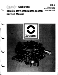
VEHICLE ID ENTIFICATION NUM BER
AND RATING PLATE
A combination vehicle identification number and rating
plate used on all models (fig. 1) is located on the left
door pillar of CK models. On Forward Control models
(except P30 Motor Home Chassis) it is attached to the
dash and toe panel.
The vehicle identification number stamped on the plate
decodes into the information shown in Figure 2.
ENGINE NUMBER
The engine number indicates manufacturing plant,
month and day of manufacture, and transmission type.
A typical engine number would be F1210TFA, which
would breakdown thus:
F - Manufacturing Plant (F-Flint, T-Tonawanda)
12 - Month of Manufacture (December)
Unit and Serial Number Locations..............................
Service Parts Identification Plate...................................
Keys and Locks....................................................................
Emergency Starting............................................................
Towing....................................................................................
10 - Day of Manufacture (tenth)
T - Truck
FA - Transmission and engine type
0-1
0-3
0-3
0-3
0-5
U N IT AND SERIAL N U M B ER LOCATIONS
For the convenience of service technicians and engineers
when writing up certain business papers such as
Warranty Reports, Product Information Reports, or
reporting product failures in any way, the location of the
various unit numbers have been indicated. These unit
numbers and their prefix or suffix are necessary on these
papers for various reasons - such as accounting, followup on production, etc.
The prefixes on certain units identify the plant in which
the unit was manufactured and thereby permits proper
follow-up of the plant involved to get corrections made
when necessary.
Always include the prefix in the number.
Axles
• Series 10, 20 and P30 Code is stamped on Front of
Right Rear Axle Tube Inboard of Upper Control
Arm Bracket.
• Series CG30 (except dual wheel) code is stamped at
the Forward Upper Surface of Carrier.
• Dual Wheel Part Number and Production Code is
stamped on Front of Right Axle Tube.
TRUCK SUPP - SERVICE
0-2 GENERAL INFORMATION AND LUBRICATION
TRUCK MODEL IDENTIFICATION
1. CH EVRO LET
C C 10703
2. CHASSIS TYPE
3. GVW RANGE 4. CA D IM E N S IO N /M O D E L TYPE
5. CAB OR BODY S T Y L E ------------
©
©
CHASSIS TYPE
CA D IM E N S IO N /M O D E L TYPE
C— Conventional 4 x 2
0 5 -B L A Z E R
G— Forward Control 4 x 2
(Body-Frame Integral)
07— 42 ”
K— Conventional 4 x 4
(Four Wheel Drive)
09— 5 6 "
P— Forward Control 4 x 2
(Conventional)
(D
GVW RANGE
1 -4 5 0 0 to 7150
08— FC or M otor Home Chassis
10— 6 0 "/F C Chassis, Chevy
Van, Sportvan
11— M otor Home Chassis
13— Chevy Van, Sportvan,
Cutaway Van
14— 8 4 "/F C or M otor Home
Chassis
©
2 -5 5 0 0 to 8200
3 -6 2 0 0 to 14,000
CAB OR BODY STY LE
03— Conventional Cab
(C-K models)
04— Cutaway Van (G models)
05— Chevy Van
06— Suburban/Sportvan w ith
Panel Rear Doors
14— Blazer
32— M otor Horne Chassis
42— Forward Control Chassis
63— Crew Cab
TRUCK SUPP • SERVICE
GENERAL INFORMATION AND LUBRICATION
0-3
Engines
• 6-Cylinder Engine Unit Number Located on Pad at
Right Hand Side of Cylinder Block at Rear of
Distributor.
• 8-Cylinder Engine Unit Number Located on Pad at
Front, Right Hand Side of Cylinder Block.
GENERAL MOTORS CORPORATION
im u n t y u r i f m m v k k n i actus m y or unncs show n c io s s
n m c u v c u i t i u u d u k j s i i or u s nmciE. mascio e d u v m u i.
w m iu n u u tti^ u c A u w m in L tA flu m T s
uonto
nmcu.
RATINGS IN POUWPS—AS MANIffjCTHED
Delcotrons
tttS S K K U V DQ n m T K V QKU
4UDMVM FMMT EHO VDOTF AT
HAliWM tU I UN VDOn tT
Delcotron Unit Serial Number Located at Top of Rear
Housing.
WKummncjimiiM. f
Batteries
□
Battery Code Number Located on Cell Cover Top of
Battery.
Starters
Fig. 1— Vehicle Identification Number and Rating
Plate Information
Starter Serial Number and Production Date Stamped on
Outer Case, Toward Rear.
SERVICE PARTS ID E N T IF IC A T IO N PLATE
ENGINE
DESIGNATION
Q = L 6 -2 5 0 -1
T= L6-292-1
V=
Y=
M=
Z=
L=
DIVISION
V 8-3 50-2
V 8 -3 5 0 -4
V 8-400-4
V 8 -4 5 4 -4
V 8-454-4
C = CHEVROLET
T = GMT
SERIES
1 ' 2 TO N
2 -%
31
5 = 1975 fo r al
Series.
C C Q 1
CHASSIS TYPE
C - 2 WHEEL DRIVE
G =LIG H T DUTY
FORWARD CONTROL
K 4 WHEEL DRIVE
L = LIGHT UTILITY
P FORWARD CONTROL
Z =M O TO R HOME
—MODEL YEAR
SEQUENTIAL NUMBER
ASSEMBLY PLANT
A -L a k e w o o d
BODY STYLE B -B altim ore
F-Flint
2-Forw ard Control
J- J an e s v ille
chassis only
K- Leeds
3-Cab-chassis (Cutaway)
4-C a b an d picku p box
5 -Van and Panel
6-S u b u rb a n bo dy
7 -M o to r Home
8 -U tility (Blazer)
V -G M Truck-P ontiac
S-St. Louis
U -Lordstow n
Z -Frem ont
1-O shaw a
3-G M A D D etroit
The Service Parts Identification Plate (fig. 3) is provided
on all Truck models. On most series it will be located on
the inside of the glove box door, or, on Forward Control
series, it will be located on an inner body panel. The
plate lists the vehicle serial number, wheelbase, and all
Production options or Special Equipment on the vehicle
when it was shipped from the factory including paint
information. ALW AYS REFER TO T H IS IN F O R M A T IO N
W H EN ORDERING PARTS.
KEYS AND LOCKS
Two keys are provided with each vehicle. Different lock
cylinders operated by a separate key are available as an
option for the sliding side load door and rear load doors.
EMERGENCY STAR TIN G
• Engines in vehicles with automatic transmissions
cannot be started by pushing or towing the vehicle.
• Never tow or push trucks equipped with light duty
emission control systems to start engine.
Fig. 2— Vehicle Identification Number
Transmissions
• 3-Speed Transmission Unit Number Located on
Lower Left Side of Case Adjacent to Rear of Cover.
• 4-Speed Transmission Unit Number Stamped on
Rear of Case, Above Output.
• Turbo Hydra-Matic 350 Transmission Unit Number
Located on Right Rear Vertical Surface of Oil Pan.
•The Turbo Hydra-Matic Transmission 400 Serial
Number is Located on the Light Blue Plate on the Right
Side of the Transmission.
IMPORTANT: RETAIN THIS PLATE AS A PERMANENT RECORD
Fig. 3— Service Parts Identification Plate
TRUCK SUPP • SERVICE
0-4 GENERAL INFORMATION AND LUBRICATION
• A vehicle with a discharged battery may be started
by transferring electrical power from a battery in
another car - called "jump starting".
Jump Starting
The following jum p start procedure
is for use only under the following conditions.
Departures from these conditions and proce
dures, could result in: (1) serious personal
injury (particularly to eyes) or property damage
from such things as battery explosion, battery
acid or electrical burns, or (2) damage to
electronic components in either vehicle. I f all
the conditions cannot be met, or if you are
uncertain about them, we strongly recommend
fo r your safety and that o f your vehicle that
you leave the starting to a competent mechanic.
• The battery in the other vehicle must be of the same
nominal voltage, 12 volts, and must be negatively
grounded. [All General Motors cars, light trucks
(10,000 GVWR and under), and motor homes use
12-volt, negatively grounded electrical systems and
can be used to jump start one another.] The nominal
voltage and grounding of the other vehicle’s battery
may be determined by checking the specifications in
its owner’s manual. Use of a booster battery of a
higher nominal voltage, or which is positively
grounded may result in serious personal injury or
property damage.
• The battery in your vehicle must be a Delco battery
(the original or a replacement) which is equipped
with flame arrestor type filler/vent caps on all filler
openings, or a sealed-type battery which does not
have filler openings or caps. Each flame arrestor cap
contains a grey disc rather than a small hole. To
help avoid serious injury or property damage, this
jump start procedure should not be used if one or
more of the flame arrestor caps is missing, or if they
are not present on a replacement battery. (If your
vehicle contains a replacement battery other than a
Delco, refer to jump starting instructions provided
by the manufacturer of the other battery.)
C A U TIO N : Never expose battery to open flame
or electric spark—battery action generates
hydrogen gas which is flammable and explo
sive. Don't allow battery fluid to contact eyes,
skin, fabrics, or painted surfaces—fluid is a
corrosive sulfuric solution which could cause
serious personal injury or property damage.
Flush any contacted area immediately with
water. Wear eye protection such as industrial
safety spectacles or goggles when working on or
near battery. Remove rings, metal watch bands
and other metal jewelry before jum p starting or
working around a battery. Be careful in using
metal tools and equipment. I f such metal
should contact the positive battery terminal (or
metal in contact with it) and any other metal
on the vehicle, a short circuit may occur which
C A U TIO N :
would cause personal injury. Batteries and
battery acid should always be kept out o f reach
o f children.
TO J U M P START:
1. Position the two vehicles so they are NOT touching.
Set parking brake firmly and place automatic
transmission in "PARK" (neutral for manual
transmission) in each vehicle. Also turn off lights,
heater and all other unnecessary electrical loads.
2. Remove the vent caps from the battery in the other
vehicle (unless it is also equipped with Delco flame
arrestor caps). Lay a cloth over the open vent wells.
These two actions help reduce the explosion hazard
always present in a battery when connecting "live"
booster batteries to "dead" batteries. For safety’s
sake, do not remove any of the flame arrestor vent
caps from a Delco battery.
3. Attach one end of one jumper cable to the positive
terminal (identified by a red color, " + " or "P" on
the battery case, post or clamp) of the battery in the
other vehicle, and the other end of the same cable
to the positive terminal of your battery.
4. Attach one end of the remaining jumper cable
FIRST to the negative terminal (black color, " —" or
"N") of the battery in the other vehicle, and THEN
the other end of the same cable to the negative
terminal of your battery in this vehicle. Take care
that clamps from one cable do not inadvertently
touch the clamps on the other cable. Do not lean
over the battery when making this connection.
5. Start the engine in the vehicle that is providing the
jump start (if it was not running). Let run a few
minutes, then start the engine in the vehicle with
the discharged battery.
6. Reverse the above sequence exactly when removing
the jumper cables. Reinstall vent caps and dispose
in a safe manner of any cloths used to cover vent
wells, as the cloths may have corrosive acid on
them.
PUSH STARTING ■ TRUC KS W ITH HEAVY
DUTY EMISSION C O N TR O L SYSTEMS
C A U TIO N : Trucks equipped with light duty
emission control systems must not be pushed or
towed to start.
If your truck is equipped with a manual 3-speed or
4-speed transmission, it can be started in an emergency
by pushing. When being pushed to start the engine, turn
off all unnecessary electrical loads, tufn ignition to
"ON", depress the clutch pedal and place the shift lever
in high gear. Release the clutch pedal when speed
reaches 10 to 15 miles per hour. Bumpers and other parts
contacted by the pushing vehicle should be protected
from damage during pushing. Never tow the truck to
start.
TRUCK SUPP - SERVICE
GENERAL INFORMATION AND LUBRICATION
0-5
STEEL TU B IN G REPLACEM ENT
TO W IN G
All Except Four Wheel Drive Trucks
Normally your vehicle may be towed with all four wheels
on the ground for distances up to 50 miles at speeds of
less than 35 MPH. The engine should be off and the
transmission in neutral.
However, the rear wheels must be raised off the ground
or the drive shaft disconnected when the transmission is
not operating properly or when a speed of 35 MPH or
distance of 50 miles will be exceeded.
C A U T IO N : I f a truck is towed on its front
wheels only, the steering wheel must be secured
with the wheels in a straight ahead position.
Four Wheel Drive Trucks
It is recommended that the truck be towed with the front
wheels off the ground. The truck can be towed, however,
with the rear wheels off the ground if there is damage in
the rear wheel area. In this event, the transmission
selector lever should be placed in the "N " (neutral)
position and with conventional four wheel drive the
front drive disengaged. With Full Time four wheel drive
the transfer case should be in high. Towing speeds
should not exceed 35 MPH for distances up to 50 miles.
If truck is towed on its front wheels, the steering wheel
should be secured to keep the front wheels in a straight
ahead position.
When towing the vehicle at slow speeds (approx. 20
MPH), for a very short distance only, the transmission
must be in NEUTRAL and with conventional four wheel
drive the transfer case MUST be in "TWO WHEEL
HIGH". With Full Time four wheel drive the transfer
case should be in high.
When towing the vehicle at faster speeds for greater
distances, the following steps MUST be taken:
• If front wheels are on the road, disconnect the front
drive shaft.
• If rear wheels are on the road, disconnect the rear
drive shaft.
In the event that replacement of steel tubing is required
on brake line, fuel line, evaporative emission, and
transmission cooling lines, only the recommended steel
replacement tubing should be used.
Only special steel tubing should be used to replace brake
line. That is, a double wrapped and brazed steel tubing
meeting G.M. Specification 123 M. Further, any other
steel tubing should be replaced only with the released
steel tubing or its equivalent. Under no condition should
copper or aluminum tubing be used to replace steel
tubing. Those materials do not have satisfactory fatigue
durability to withstand normal vehicle vibrations.
All steel tubing should be flared using the upset (double
lap) flare method which is detailed in Section 5 of this
Manual.
VEHICLE LOADING
Vehicle loading must be controlled so weights do not
exceed the numbers shown on the Vehicle Identification
Number and Rating Plate for the vehicle.
A typical example of a truck in a loaded condition is
shown in Figure 4. Note that the axle or GVW
capabilities are not exceeded.
LOADED-MAXIMUM GVW : 6000-LBSFRONT AXLE CAPACITY: 3 2 5 0 LBS.
Front Curb
Front C argo
Load
2 1 0 0 lbs.
4 0 0 lbs.
2 5 0 0 lbs.
REAR AXLE CAPACITY: 3 5 8 2 LBS.
Rear C urb
Rear C argo
Load
1 5 8 5 lbs.
1915 lbs.
3 5 0 0 lbs.
TOTAL W EIGHT AT G R O U N D : 6 0 0 0 lbs.
Fig. 4— Typical Vehicle Loaded Condition
LUBRICATION
INDEX
Maintenance Schedule........................................................
Engine.....................................................................................
Oil and Filter Recommendations................................
Drive Belts...........................................................................
Positive Crankcase Ventilation.....................................
Air Injection Reactor System.......................................
Controlled Combustion System....................................
GM Evaporation Control System................................
Manifold Heat Control Valve......................................
Air Cleaner..........................................................................
0-6
0-6
0-6
0-7
0-7
0-7
0-7
0-7
0-7
0-8
Fuel Filter............................................................................
Governor..............................................................................
Accelerator Linkage..........................................................
Automatic Transmission Fluid Recommendations...
Manual Transmission.........................................................
Transmission Shift Linkage.............................................
Clutch.......................................................................................
Rear Axle...............................................................................
Standard...............................................................................
Propeller Shaft Slip Joints...............................................
0-8
0-8
0-8
0-8
0-8
0-8
0-8
0-9
0-9
0-9
TRUCK SUPP • SERVICE
0-6 GENERAL INFORMATION AND LUBRICATION
Universal Joints................................................................... 0-9
Wheel Bearings
Front...................................................................................... 0-9
R ear....................................................................................... 0-9
Brake Master Cylinder...................................................... 0-9
Brake and Clutch Pedal Springs................................... 0-9
Parking Brake....................................................................... 0-9
Steering
Manual Steering G ear..................................................... 0-9
Steering Linkage and Suspension................................ 0-9
Hood Latch and Hood Hinge...................................... 0-10
Body Lubrication............................................................... 0-10
MAINTENANCE SCHEDULE
A separate maintenance folder has been provided with
each vehicle which contains a complete schedule and
brief explanation of the safety, emission control,
lubrication and general maintenance it requires. The
maintenance folder information is supplemented by this
section of this manual, as well as the separate vehicle
and emissions warranty booklet also furnished with each
vehicle. Read all three publications for a full
understanding of vehicle maintenance requirements.
The time or mileage intervals for lubrication and
maintenance services outlined in this section are
intended as a general guide for establishing regular
maintenance and lubrication periods for trucks with light
duty emission control systems (see chart). Sustained
heavy duty and high speed operation or operation under
adverse conditions may require more frequent servicing.
For maintenance and iubrication information on trucks
designated with heavy duty emission control systems,
continue to refer to Section 0 of the 1974 Light Duty
Truck Shop Manual.
CHEVRO LET LIG H T AN D H E A VY D UTY
EMISSION CLASS VEH IC LES
Light Duty:
C10 (exc. Suburban V-8 & 6200# GVW
L-6 or V-8)
K10 - L6 Only
G10 - All
Heavy Duty Vehicle:
C10 - Suburban V-8
C10 - 6200# GVW L-6 or V-8
K10 - V-8 Only
C20, 30 - All
K20 - All
P10, 20, 30 - All
G20, 30 - All
Four Wheel Drive
Propeller Shaft Centering Ball...................................
Front Axle.........................................................................
Air Vent Hose.................................................................
Transfer Case....................................................................
Control Lever and Linkage........................................
Speedometer Adapter......................................................
Complete Maintenance Schedule.................................
Lubrication Diagrams
Conventional and Forward Control Models.........
Four Wheel Drive Models..........................................
1/2 ton G Models..........................................................
0-10
0-10
0-11
0-11
0-11
0-11
0-12
0-19
0-20
0-21
ENGINE
Oil and Filter Recom m endations
The letter designation "SE" has been established to
correspond with the requirements of GM 6136-M. "SE"
engine oils will be better quality and perform better than
those identified with "SA" through "SD" designations
and are recommended for all light-duty gasoline trucks
regardless of model year and previous engine oil quality
recommendations.
Oil Change Period
• Use only SE engine oil.
• Change oil each 6 months or 7,500 miles. If more
than 7,500 miles are driven in a 6 month period,
change oil each 7,500 miles.
• Change oil each 3 months or 3,000 miles, whichever
occurs first, under the following conditions:
—Driving in dusty conditions.
—Trailer pulling or camper use.
—Frequent long runs at high speeds and high
ambient temperatures.
—Motor Home use.
—Stop and go type service such as delivery trucks,
etc.
—Extensive idling.
—Short-trip operation at freezing temperatures
(engine not thoroughly warmed-up).
• Operation in dust storms may require an immediate
oil change.
• Replace the oil filter at the first oil change, and
every second oil change thereafter. AC oil filters
provide excellent engine protection.
The above recommendations apply to the first change as
well as subsequent oil changes. The oil change interval
for the engine is based on the use of SE oils and quality
oil filters. Oil change intervals longer than those listed
above will seriously reduce engine life and may affect the
manufacturer’s obligation under the provisions of the
New Vehicle Warranty.
A high quality SE oil was installed in the engine at the
factory. It is not necessary to change this factoryinstalled oil prior to the recommended normal change
TRUCK SUPP • SERVICE
GENERAL INFORMATION AND LUBRICATION
0-7
period. However, check the oil level more frequently
during the break-in period since higher oil consumption
is normal until the piston rings become seated.
NOTE: Non-detergent and other low quality oils
are specifically not recommended.
The oil level should be maintained in the safety margin,
neither going above the "FULL" line nor below "ADD
OIL" line.
NOTE: The oil gauge rod is also marked "Use SE
Engine Oil" as a reminder to use only SE oils.
Oil Filter Type and Capacity
Supplemental Engine Oil Additives
• Throwaway type, 1 quart U.S. measure, .75 quart
Imperial measure.
• 250 cu. in., 292 cu. in., AC Type PF-25. 350 cu. in.
454 cu. in., AC Type PF-35.
Crankcase Capacity (Does N o t Include Filter)
• 2 9 2 L6 Engine; 5 quarts U.S. measure, 4 .2 5
quarts
Im perial measure.
The regular use of supplemental additives is specifically
not recommended and will increase operating costs.
However, supplemental additives are available that can
effectively and economically solve certain specific
problems without causing other difficulties. For example,
if higher detergency is required to reduce varnish and
sludge deposits resulting from some unusual operational
difficulty, a thoroughly tested and approved additive "Super Engine Oil Supplement" - is available.
Drive Belts
• All other engines; 4 quarts U.S. measure, 3.25
quarts
Imperial measure.
Drive belts should be checked every 7,500 miles or 6
months for proper tension. A loose belt will affect water
pump and generator operation.
Recomm ended Viscosity
POSITIVE CRANKCASE V E N TIL A TIO N
VALVE
Select the proper oil viscosity from the following chart:
RECOMMENDED SAE VISCOSITY NUMBER
Every 30,000 miles or 24 months the valve should be
replaced. Connecting hoses, fittings and flame arrestor
should be cleaned. At every oil change the system should
be tested for proper function and serviced, if necessary.
(Also see maintenance schedule at end of this section.)
AIR INJECTIO N REACTOR SYSTEM (A.I.R.)
CONTROLLED C O M B U S T IO N SYSTEM
(C.C.S.)
-3 0
-2 0
0
20
40
60
80
TEMPERATURE RANGE ANTICIPATED BEFORE NEXT OIL CHANGE, °F.
100
NOTE: SAE 5W-20 oils are not recommended for
sustained high-speed driving. SAE 30 oils may be
used at temperatures above 40 °F. SAE 5W-30 oils
are recommended for all seasons in vehicles
normally operated in Canada.
The proper oil viscosity helps assure good cold and hot
starting.
Checking Oil Level
The engine oil should be maintained at proper level. The
best time to check it is before operating the engine or as
the last step in a fuel stop. This will allow the oil
accumulation in the engine to drain back in the
crankcase. To check the level, remove the oil gauge rod
(dipstick), wipe it clean and reinsert it firmly for an
accurate reading. The oil gauge rod is marked "FULL"
and "ADD OIL". If the oil is at or below the "ADD"
mark on the dipstick, oil should be added as necessary.
The Air Injection Reactor system should have the drive
belt inspected for wear and tension every 24 months or
30,000 miles, whichever occurs first. In addition,
complete effectiveness of either system, as well as full
power and performance, depends upon idle speed,
ignition timing, and idle fuel mixture being set
according to specification. A quality tune-up which
includes these adjustments should be performed
periodically to assure normal engine efficiency, operation
and performance.
GM EVAPO RATIO N C O N TR O L SYSTEM
Every 24 months or 30,000 miles (more often under
dusty conditions) the filter in the base of the canister
must be replaced and the canister inspected.
MANIFO LD HEAT CO NTRO L VALVE
First 7,500 miles or 6 months check valve for freedom of
operation. If valve shaft is sticking, free it up with GM
Manifold Heat Control Solvent or its equivalent.
TRUCK SUPP ■ SERVICE
0-8 GENERAL INFORMATION AND LUBRICATION
AIR CLEANER
C A U TIO N : Do not remove the engine air
cleaner unless temporary removal is necessary
during repair or maintenance o f the vehicle.
When the air cleaner is removed backfiring can
cause fire in the engine compartment.
NOTE: Under prolonged dusty driving conditions,
it is recommended that these operations be
performed more often.
011 Wetted Paper Elem ent Type
L-6 engine, replace every 15,000 miles. V-8 engine, every
15,000 miles inspect inspect element for dust leaks, holes
or other damage. Replace if necessary. If satisfactory,
rotate element 180° from originally installed position.
Replace at 30,000 miles. Element must not be washed,
oiled, tapped or cleaned with an air hose.
Crankcase Ventilation Filter
(Located W ithin Air Cleaner)
If so equipped, inspect every oil change and replace if
necessary. Replace at least every 30,000 miles; more
often under dusty driving conditions.
FUEL FILTER
Replace filter element located in carburetor inlet every
12 months or 15,000 miles whichever occurs first, or, if
an in-line filter is also used, every 30,000 miles. Replace
in-line filtc every 30,000 miles.
GOVERNOR
The attaching bolts should be kept tight, the optionally
available governor should be kept clean externally and
the filter element should be replaced every 15,000 miles.
and stops, to bring transmission up to normal
operating temperature (approximately 180-190®F).
2. Park vehicle on a level surface.
3. Place selector lever in "Park" and leave engine
running.
4. Remove dipstick and wipe clean.
5. Reinsert dipstick until cap seats.
6. Remove dipstick and note reading.
If oil level is at or below the ADD mark on the dipstick,
oil should be added as necessary. One pint raises the
level from ADD to FULL. Do not overfill.
Under normal driving conditions, the transmission fluid
should be changed every 30,000 miles. If the vehicle is
driven extensively in heavy city traffic during hot
weather, or is used to pull a trailer, change fluid every
15,000 miles. Likewise, operators of trucks in commercial
use where the engine idles for long periods, should
change fluid every 15,000 miles.
To Change Turbo H ydra-M atic 4 0 0 and Turbo HydraM atic 3 5 0 fluid, remove fluid from the transmission
sump, add approximately 7.5 pints U.S. measure (6.25
pints Imperial measure) for the Turbo Hydra-Matic 400
and 2 1/2 qts. U.S. measure (2 qts. Imperial measure) for
the Turbo Hydra-Matic 350 of fresh fluid, to return level
to proper mark on the dipstick.
Every 3 0 ,0 0 0 M iles—the Turbo Hydra-Matic 400
transmission sump filter should be replaced.
3-AND 4-SPEED M A N U A L T R A N M IS S IO N
LUBRICANT
Every 6 months or 7,500 miles, whichever occurs first,
check lubricant level and add lubricant, if necessary, to
fill to lvel of filler plug hole with SAE 80W or SAE 80W90 GL-5 Gear Lubricant. If temperatures below +32°F
are expected, use SAE 80W GL-5 Gear Lubricant only.
For those vehicles normally operated in Canada, use
SAE 80W GL-5 Gear Lubricant only.
ACCELERATOR LINKAGE
Lubricate with engine oil every 30,000 miles as follows:
1. On V8 engine, lubricate the ball stud at the
carburetor lever.
2. On L6 engine, lubricate the two ball studs at the
carburetor lever and lubricate the lever mounting
stud. Do not lubricate the accelerator cable.
A U T O M A T IC T R A N S M IS S IO N
FLUID R E C O M M E N D A TIO N
Use only automatic transmission fluids identified with
the mark DEXRON® II (or equivalent).
Check the fluid level at each engine oil change period.
To make an accurate fluid level check:
1. Drive vehicle several miles, making frequent starts
TR A N SM IS SIO N SHIFT LINKAGE
(M A N U A L AND A U T O M A T IC )
Every 7,500 miles or 6 months-lubricate shift linkage
and, on Manual transmission floor control, lever
contacting faces with water resistant EP chassis lubricant
which meets General Motors Specification GM6031-M.
Clutch
The clutch pedal free travel should be checked at regular
intervals.
Lubricate the clutch cross-shaft at fitting (on Series 10
Forward Control models also lubricate the clutch linkage
idler lever at fitting) every 7,500 miles or 6 months with
water resistant EP chassis lubricant which meets General
Motors Specification GM 6031-M.
TRUCK SUPP - SERVICE
GENERAL INFORMATION AND LUBRICATION
REAR AXLES
Standard
Every 6 months or 7,500 miles, whichever occurs first,
check lubricant level and add lubricant, if necessary, to
fill to level of filler plug hole. Use SAE 80W or SAE
80W-90 GL-5 Gear Lubricant. For those vehicles
normally operated in Canada, use SAE 80W GL-5 Gear
Lubricant.
Positive Locking or Positraction
Every 6 months or 7,500 miles, whichever occurs first,
check lubricant level and add lubricant, if necessary, to
fill to level of filler plug hole.
Drain and refill at first 15,000 miles then maintain same
as standard axle but, use only the special positraction
differential lubricant available at your authorized
Chevrolet dealer.
PROPELLER SHAFT SLIP JO IN TS
Propeller shaft slip joints should be lubricated every
7,500 miles or 6 months with water resistant EP chassis
lubricant which meets General Motors Specification GM
6031-M.
UNIVERSAL JOINTS
All universal joints are the needle bearing type.
Lubricate those universal joints (depending on truck
model) equipped with lube fittings every 7,500 miles or 6
months with water resistant EP chassis lubricant which
meets General Motors Specification GM 6031-M. More
frequent lubes may be required on heavy duty or "Off
the Road" operations.
WHEEL BEARINGS
Front
NOTE: Use wheel bearing lubricant GM Part No.
1051344 or equivalent. This is a premium high
melting point lubricant which meets all require
ments of General Motors Specification GM 6031M.
Due to the weight of the tire and wheel assembly it is
recommended that they be removed from hub before
lubricating bearings to prevent damage to oil seal. Then
remove the front wheel hub to lubricate the bearings.
The bearings should be thoroughly cleaned before
repacking with lubricant.
Front wheels are equipped with tapered roller bearings
on all trucks. Wheel bearings should be lubricated every
30,000 miles. Do not mix wheel bearing lubricants.
C A U TIO N : "Long fibre " type greases should
not be used on roller bearing front wheels.
0-9
Rear
The rear wheel bearings receive their lubrication from
the rear axle. When installing bearings which have been
cleaned, prelube with wheel bearing grease.
BRAKE MASTER CYLINDER
Check master cylinder fluid level in both reservoirs every
7,500 miles or 6 months. If the fluid is low in the
reservoir, it should be filled to a point about 1/4" from
the top rear of each reservoir with Delco Supreme No.
11 Hydraulic Brake Fluid or equivalent.
BRAKE AND CLUTCH PEDAL SPRING S
Lubricate brake and clutch pedal springs every 7,500
miles or 6 months with engine oil for all models.
PARKING BRAKE
Every 7,500 miles or 6 months clean and lubricate all
parking brake pivot points with water resistant EP
chassis lubricant which meets General Motors Specifica
tion GM 6031-M.
STEERING
Manual Steering Gear
The steering gear is factory-filled with steering gear
lubricant. Seasonal change of this lubricant should not
be performed and the housing should not be drained-no
lubrication is required for life of the steering gear.
Every 30,000 miles, the gear should be inspected for seal
leakage (actual solid grease-not just oily film). If a seal is
replaced or the gear is overhauled, the gear housing
should be refilled with No. 1051052 (13 oz. container)
Steering Gear Lubricant which meets GM Specification
GM4673-M or its equivalent.
NOTE: Do not use EP Chassis Lube, which meets
GM Specification GM 6031-M, to lubricate the
gear. DO NOT OVER-FILL the gear housing.
Power Steering System
Check the fluid level in the pump reservoir at each oil
change period. Add GM Power Steering Fluid or
DEXRON® II automatic Transmission Fluid) or
equivalent as necessary to bring level into proper range
on filler cap indicator depending upon fluid temperature.
If at operating temperature (approximately 150°F—hot to
the touch), fluid should be between "HOT" and
"COLD" marks.
If at room temperature (approximately 70 °F), fluid
should be between "ADD" and "COLD" marks. Fluid
does not require periodic changing.
STEERING LINKAGE AND SUSPENSION
Maintain correct front end alignment to provide easy
steering, longer tire life, and driving stability.
TRUCK SUPP - SERVICE
0-10 GENERAL INFORM ATION AND LUBRICATION
Check control arm bushings and ball joints for wear.
Lubricate tie rods, upper and lower control arms, and
ball joints at fittings with water resistant EP chassis
lubricant which meets General Motors Specification GM
6031-M every 7,500 miles or 6 months.
Lubricate every 3,000 miles or 3 months whichever
occurs first under the following conditions:
• Driving in dusty or muddy conditions.
• Extensive off-road use.
NOTE: Ball joints must be at +10°F. or more
before lubricating.
Keep spring to axle U bolts and shackle bolts properly
tightened (see Specifications Section for torque recom
mendations). Check U bolt nuts after the first 1,000 miles
of operation if the U bolt or U bolt nuts are changed in
service.
HOOD LATCH AND HOOD HINGE
Every 7,500 miles or 6 months, whichever occurs first,
lubricate hood latch assembly and hood hinge assembly
as follows:
1. Wipe off any accumulation of dirt or contaimination on latch parts.
2. Apply lubriplate or equivalent to latch pilot bolt
and latch locking plate.
3. Apply light engine oil to all pivot points in release
mechanism, as well as primary and secondary latch
mechanisms.
4. Lubricate hood hinges.
5. Make hood hinge and latch mechanism functional
check to assure the assembly is working correctly.
BODY LUBRICATIO N
Normal use of a truck causes metal-to-metal movement
at certain points in the cab or body. Noise, wear and
improper operation at these points will result when a
protective film of lubricant is not provided.
For exposed surfaces, such as door checks, door lock
bolts, lock striker plates, dovetail bumper wedges, etc.
apply a thin film of light engine oil.
Where oil holes are provided in body parts a dripless oil
can be safely used, but any lubricant should be used
sparingly, and after application all excess should be
carefully wiped off.
The seat adjusters and seat track, ordinarily overlooked,
should be lubricated with water resistant EP chassis
lubricant which meets General Motors Specification GM
6031-M.
There are other points on bodies which may occasionally
require lubrication and which are difficult to service,
window regulators and controls are confined in the space
between the upholstery and the outside door panel. Easy
access to the working parts may be made by removing
the trim. Door weatherstrips and rubber hood bumpers
should be lightly coated with a rubber lubricant.
UNDERBODY M A IN T E N A N C E
The effects of salt and other corrosive materials used for
ice and snow removal and dust control can result in
accelerated rusting and deterioration of underbody
components such as brake or pan, exhaust system,
brackets, parking brake cables. These corrosive effects,
however, can be reduced by periodic flushing of the
underbody with plain water. In geographic areas having
a heavy concentration of such corrosive materials, it is
recommended that the complete underbody be inspected
and flushed at least once a year, preferably after a
winter’s exposure. Particular attention should be given to
cleaning out underbody members where dirt and other
foreign materials may have collected.
FOUR WHEEL DRIVE
Most lubrication recommendations and procedures for 4
wheel drive-equipped trucks are the same for corre
sponding components of conventional drive trucks.
In addition, the following items require lubrication at the
intervals mentioned.
Propeller S haft Centering Ball
A centering ball at the transfer case end of the front
propeller shaft on Four Wheel Drive Models should be
lubricated every 7,500 miles with water resistant EP
chassis lubricant which meets General Motors Specifica
tion GM 6031-M. More frequent lubrication may be
required on heavy duty off the road operations.
NOTE: A special needle nose grease gun adapter
for flush type grease fitting is required to lubricate
the centering ball.
Front Axle
The front axle should be checked every 7,500 miles or 6
months and refilled with SAE 80W-90 GL-5 Gear
Lubricant when necessary. With the differential at
operating temperature, fill to the level of filler plug hole.
TRUCK SUPP - SERVICE
GENERAL INFORMATION AND LUBRICATION
If differential is cold, fill to level of 1/2" below the filler
plug hole.
For vehicles normally operated in Canada use SAE 80W
GL-5 Gear Lubricant.
Air Vent Hoses
0-11
Fu ll Time Four Wheel Drive
Add SAE 10W-30 or SAE 10W-40 engine oil to bring to
level 1/ 2" below filler plug hole.
Control lever and Linkage
Transfer Case
Since no grease fitting is provided in the control ever it is
necessary to brush or spray engine oil on the lever pivot
point and on all exposed control linkage every 7,500
miles 6 months.
Check the transfer case level every 7,500 miles or 6
months and, if necessary, add lubricant as follows:
SPEEDOMETER ADAPTER
Check vent hose at front axle and at transfer case for
kinks and proper installation every 7,500 miles or 6
months.
Conventional Four Wheel D rive
Add SAE 80W or SAE 80W-90 GL-5 Gear Lubricant to
bring to level of filler plug hole.
On vehicles so equipped, lubricate adapter at fitting with
water resistant EP chassis grease which meets General
Motors Specification GM 6031-M every 7,500 miles.
TRUCK SUPP
SERVICE
0-12 GENERAL INFORMATION AND LUBRICATION
COMPLETE VEHICLE MAINTENANCE SCHEDULE
When To Perform Services
(Months or Miles, Whichever Occurs First)
Item
No.
Every 6 Months or 7,500 Miles
1
2
3
4
5
6
7
8
At 1st Oil Chg. - Then Every 2nd
See Explanation
Every 12 Months
Every 12 M onths or 15,000 Miles
Every 30,000 Miles
Every 6 M onths or 7,500 Miles
Every 12 Months or 15,000 Miles
At First 6 M onths or 7,500
Miles - Then at 18 Month/
22,500 Mile Intervals
Every 12 Months or 15,000 Miles
Every 18 M onths or 22,500 Miles
Every 22,500 Miles
Every 24 M onths or 30,000 Miles
Every 30,000 Miles
9
10
11
12
13
14
15
16
17
18
19
20
21
22
23
24
25
26
27
28
29
30
31
32
33
34
35
36
37
Services
(For Details, See Numbered Paragraphs)
*Chassis Lubrication
•*F luid Levels Check
*Engine Oil Change
*Oil Filter Change
Tire Rotation (Steel Belted Radial)
Rear Axle Lube Change
A ir Conditioning Check
*Cooling System Check
— Coolant Change & Hose Replacement
Wheel Bearing Repack
*Auto. Trans. Fluid & Filter Change
Manual Steering Gear Check
Clutch Cross Shaft Lubrication
Owner Safety Checks
Tire and Wheel Inspection
*Exhaust System Check
*Drive Belt Check
*— Belt Replacement
Suspension and Steering Check
Brake and Power Steering Check
Drum Brake and Parking Brake Check
Throttle Linkage Check
Underbody Flush & Check
Bumper Check
Thermo. Controlled A ir Cleaner Check
Carburetor Choke Check
Engine Idle Speed Adjustm ent
EFE Valve Check
Carburetor M ounting Torque
Fuel Filter Replacement
Vacuum Advance System & Hoses Check
PCV System Check
— PCV Valve & Filter Replacement
Idle Stop Solenoid Check
Spark Plug Wires Check
Spark Plug Replacement
Engine Tim ing Adjustm ent & Dist. Check
ECS System Check & Filter Replacement
Fuel Cap, Tank and Lines Check
A ir Cleaner Element Replacement
• Also A Safety Service
* Also An Emission Control Service
TRUCK SUPP ■ SERVICE
GENERAL INFORMATION AND LUBRICATION
EXPLANATION OF COMPLETE
VEHICLE MAINTENANCE
SCHEDULE
Presented below is a brief explanation of each of the
services listed in the preceding Complete Vehicle
Maintenance Schedule.
Vehicle operation under conditions such as heavy dust,
continuous short trips, use of other than unleaded or low
lead fuels or pulling trailers, is not considered normal
use and therefore more frequent maintenance will be
required. Such additional maintenance requirements are
included where applicable. Refer to the appropriate
section of this manual for additional details on specific
services. A listing of recommended lubricants and fluids
is included at the end of this listing.
LUBE AND GENERAL
MAINTENANCE
1. CHASSIS**-Lubricate all grease fittings in front
suspension and steering linkage. Also lubricate
transmission shift linkage, hood latch, hood hinges,
and parking brake cable guides and linkage, clutch
linkage, propeller shaft slip joint, universal joints
and brake and clutch pedal springs. Lubricate
suspension and steering linkage every 3 months or
3,000 miles when operating under dusty or muddy
conditions and in extensive off-road use. (See
elsewhere in this section for additional services
required on four wheel drive models.)
2. FLUID LEVELS-Check level of fluid in brake
master cylinder*, power steering pump*, battery,
engine**, axle, transmission** and windshield
washer*. Engine coolant should be checked for
proper level and freeze protection to at least —20 °F
or to the lowest temperature expected during the
period of vehicle operation.** Proper engine
coolant also provides corrosion protection.
Any significant fluid loss in any of these systems or
units could mean that a malfunction is developing and
corrective action should be taken immediately. A low
fluid level in the brake master cylinder front reservoir
could also be an indicator that the disc brake pads need
replacing.
3. ENGINE OIL**—Change each 6 months or 7,500
miles, whichever occurs first under normal driving
conditions, or each 3 months or 3,000 miles when
the vehicle is operated under the following
conditions: (a) driving in dusty conditions, (b)
trailer pulling, (c) extensive idling or (d) short-trip
operation at freezing temperatures (with engine not
thoroughly warmed-up). See elsewhere in this
section for additional details on engine oil.
4.
ENGINE O IL FITLER **-Replace at the first oil
change and every other oil change thereafter.
5. TIRES-Steel belted radial tires should be rotated at
0-13
first 7,500 miles and then at every 15,000 miles
thereafter. Bias-belted tires should be rotated every
7,500 miles. To equalize wear, rotate tires as
illustrated in Section 10 of this manual and adjust
tire pressures as shown on Tire Inflation Table in
Section 10 of this manual.
6. REAR AXLE—Change lubricant at first 15,000 miles
on positraction axles. Change lubricant every 7,500
miles on all typo rear axles or final drives when
using vehicle to pull a trailer.
7. AIR C O N D IT IO N IN G —Check condition of air
conditioning system hoses and refrigerant charge at
sight glass (if so equipped). Replace hoses and/or
refrigerant if need is indicated.
8. CO OLING S Y S T E M **— 12 month or 15,000-mile
intervals, wash radiator cap and filler neck with
clean water, pressure test system and radiator cap
for proper pressure holding capacity, (tighten hose
clamps and inspect condition of all cooling and
heater hoses). Replace hoses every 24 months or
30,000 miles, or earlier if checked, swollen or
otherwise deteriorated.
Also each 12 months or 15,000 miles, clean exterior of
radiator core and air conditioning condenser. Every 24
months or 30,000 miles, drain, flush, and refill the
cooling system with a new coolant solution.
9. WHEEL BEARINGS-Clean and repack front wheel
bearings with a lubricant as specified in the
“Recommended Fluids and Lubricants" chart in this
section.
10. A U TO M A TIC
TRANSMISSION
F L U ID * * —
Under normal driving conditions, change the trans
mission fluid and service the sump filter every 30,000
miles.
Under unusual conditions such as constant driving in
heavy city traffic, trailer pulling, and commercial
applications, services should be performed at 15,000 mile
intervals. See elsewhere in this manual for further details
on transmission care.
11. M A N U A L STEERING GEAR—Check for seal leakage
around the pitman arm and housing. If leakage is
evident (solid grease oozing out-not just oily film),
it should be corrected immediately.
12. CLUTCH CROSS SHAFT—Lubricate clutch cross
shaft lever.
SAFETY MAINTENANCE
NOTE: Items a thru u can be checked by the
owner, while Items 14 thru 22 should only be
checked by a qualified mechanic. It is particularly
important that any safety systems which may have
been adversely affected in an accident be checked
and repaired as necessary before the vehicle is
returned to use.
* Also a Safety Service
** Also an Emission Control Service
TRUCK SUPP • SERVICE
0-14 GENERAL INFORMATION AND LUBRICATION
13. SAFETY CHECKS TO BE PERFORMED BY
OWNER—The following checks should be made
regularly during operation at no greater interval
than 6 months or 7,500 miles, whichever occurs
first, and more often when the need is indicated.
Any deficiencies should be brought to the attention
of your dealer or another service outlet, as soon as
possible, so the advice of a qualified mechanic is
available regarding the need for repairs or
replacements.
(a) STEERING COLUMN LOCK-Check for proper
operation by attempting to turn key to LOCK
position in the various transmission gears with
car stationary. Key should turn to LOCK
position only when transmission control is in
PARK on automatic transmission models or in
reverse on manual transmission models. Key
should be removable only in LOCK position.
(b) PARKING BRAKE AND TRANSMISSION
"PARK" MECHANISM-Check parking brake
holding ability by parking on a fairly steep hill
and restraining the vehicle with the parking
brake only. On vehicles with automatic
transmissions, check the holding ability of the
"PARK" mechanism by releasing all brakes
after the transmission selector lever has been
placed in the "P" position.
CAUTION: Before making the two checks
below, be sure to have a clear distance ahead
and behind the car, set the parking brake and
firmly apply the foot brake. Do not depress
accelerator pedal. Be prepared to turn off
ignition switch immediately if engine should
start.
(c) STARTER SAFETY SWITCH (AUTOMATIC
TRANSMISSION VEHICLES>~Check starter
safety switch by attempting to start the engine
with the transmission in each of the driving
gears. The starter should operate only in the
Park ("P") or Neutral ("N") positions.
(d) STARTER, SAFETY SWITCH (MANUAL
TRANSMISSION VEHICLES)-To check, place
the shift lever in neutral, depress the clutch
halfway, and attempt to start. The starter
should operate only when clutch is fully
depressed.
(e) TRANSMISSION SHIFT INDICATOR—Check to
be sure automatic transmission shift indicator
accurately indicates the shift position selected.
(f) STEERING—Be alert to any changes in steering
action. The need for inspection or servicing
may be indicated by "hard" steering, excessive
free play or unusual sounds when turning or
parking.
(g) WHEEL ALIGNMENT AND BALANCE—In
addition to uneven or abnormal tire wear, the
need for wheel alignment service may be
(h)
(i)
(j)
(k)
(1)
(m)
(n)
(o)
(p)
(q)
(r)
indicated by a pull to the right or left when
driving on a straight and level road. The need
for wheel balancing is usually indicated by a
vibration he steering wheel or seat while
driving at normal highway speeds.
BRAKES-Be alert to illumination of the brake
warning light or changes in braking action,
such as repeated pulling to one side, unusual
sounds either when braking or between brake
applications, or increased brake pedal travel.
Any of these could indicate the need for brake
system inspection and/or service.
EXHAUST SYSTEM^Be alert to any change in
the sound of the exhaust system or a smell of
fumes which may indicate a leak.
WINDSHIELD WIPERS AND WASHERS-Check
operation of wipers, as well as condition and
alignment of wiper blades. Check amount and
direction of fluid sprayed by washers during
use.
DEFROSTERS-Check performance by moving
controls to "D EF" and noting amount of air
directed against the windshield.
REARVIEW MIRRORS AND SUN VISORSCheck that friction joints are properly adjusted
so mirrors and sun visors stay in the selected
position.
HORN—Blow the horn occasionally to be sure
that it works. Check all button locations.
LAP AND SHOULDER BELTS-Check belts,
buckles, adjustable latch plates, retractors,
interlock and reminder systems, guide loops,
clips, and anchors for impaired operation or
damage. Check to make certain that anchor
mounting bolts are tight.
HEAD RESTRAINTS—Check that head re
straints, if present, adjust properly in the up
detent positions, and that no components are
missing, damaged or loose.
SEAT BACK LATCHES-Check to see that seat
back latches are holding by pulling forward on
the top of each folding seat back (with doors
closed if equipped with automatic seat back
latches).
LIGHTS AND BUZZERS-Check all instrument
panel illuminating and warning lights, seat belt
reminder light and buzzer, ignition key buzzer,
interior lights, license plate lights, side marker
lights, headlamps, parking lamps, tail lamps,
brake lights, turn signals, backup lamps, and
hazard warning flashers. Have headlamp aim
checked every 12 months or 15,000 miles, or
more often if light beams seem to be aimed
improperly.
GLASS-Check for broken, scratched, dirty or
TRUCK SUPP - SERVICE
GENERAL INFORMATION AND LUBRICATION
damaged glass on vehicle that could obscure
vision or become an injury hazard.
(s) DOOR LATCHES-Check for positive closing,
latching and locking.
(t) HOOD LATCHES-Check to make sure hood
closes firmly by lifting on the hood after each
closing. Check also for broken, damaged or
missing parts which might prevent secure
latching.
(u) FLUID LEAKS-Check for fuel, water, oil or
other fluid leaks by observing the ground
beneath the vehicle after it has been parked
for a while. (Water dripping from air
conditioning system after use is normal.) If
gasoline fumes or fluid are noticed at any time,
the cause should be determined and corrected
without delay because of the possibility of fire.
14. TIRES AND WHEELS-To equalize wear, rotate tires
as illustrated in Section 10 in this manual. Adjust
tire pressures as recommended on tire placard on
left front door. Check disc brake pads and
conditions of rotors while wheels are removed.
Check tires for excessive wear or damage. Make
certain wheels are not bent or cracked and wheel
nuts are tight. Check tire inflation pressure at least
monthly, or more often if daily visual inspection
indicates the need.
15. EXHAUST SYSTEM**—Check complete exhaust
system and nearby body areas and trunk lid for
broken, damaged, missing or mispositioned parts,
open seams, holes, loose connections or other
deterioration which could permit exhaust fumes to
seep into the trunk or passenger compartment. Dust
or water in the trunk may be an indication of a
problem in one of these areas. Any defects should
be corrected immediately. To help insure continued
integrity, exhaust system pipes and resonators
rearward of the muffler must be replaced whenever
a new muffler is installed.
16. ENGINE DRIVE BELTS**—Check belts driving fan,
AIR pump, Delcotron, power steering pump and air
conditioning compressor for cracks, fraying, wear
and tension. Adjust or replace as necessary.
It is recommended that belts be replaced every 24
months or 30,000 miles, whichever occurs first.
17. SUSPENSION AND STEERING-Check for dam
aged, loose or missing parts, or parts showing
visible signs of excessive wear or lack of lubrication
in front and rear suspension and steering system.
Questionable parts noted should be replaced by a
qualified mechanic without delay.
18. BRAKES AND POWER STEERING-Check lines and
hoses for proper attachment, leaks, cracks, chafing,
deterioration, etc. Any questionable parts noted
should be replaced or repaired immediately. When
abrasion or wear is evident on lines or hoses, the
cause must be corrected.
0-15
19
DRUM BRAKES AND PARKING BRAKE- Check
drum brake linings and other internal brake
components at each wheel (drums, wheel cylinders,
etc.). Parking brake adjustment also should be
checked whenever drum brake linings are checked.
NOTE: More frequent brake checks should be
made if driving conditions and habits result
in frequent brake application.
20. THROTTLE LINKAGE- Check for damaged or
missing parts, interference or binding. Any
deficiencies should be corrected without delay by a
qualified mechanic.
21. UNDERBODY—In geographic areas using a heavy
concentration of road salt or other corrosive
materials for snow removal or road dust control,
flush and inspect the complete underside of the car
at least once each year, preferably after a winter’s
exposure. Particular attention should be given to
cleaning out underbody members where dirt and
other foreign materials may have collected.
22. BUMPERS-Check the front and rear bumper
systems at 12-month/15.000 mile intervals to be
sure that impact protection and clearance originally
designed into these systems remain in a state of full
readiness. They also should be checked whenever
there is obvious bumper misalignment, or whenever
the vehicle has been involved in a significant
collision in which the bumpers were struck, even
when slight or no damage to the bumper systems
can be seen.
EMISSION CONTROL
MAINTENANCE
23
24
25.
26.
NOTE: Additional recommended maintenance
instructions relating to vehicle use, evidence of
maintenance, and service replacement parts are
included in the New Vehicle Warranty Information
folder.
THERMOSTATICALLY
CONTROLLED
AIR
CLEANER-Inspect installation to make certain that
all hoses and ducts are connected and correctly
installed. Also check valve for proper operation.
CARBURETOR CHOKE AND HOSES^ Check choke
mechanism for proper operation. Any binding
condition which may have developed due to
petroleum gum formation on the choke shaft or
from damage should be corrected. Check carburetor
choke hoses for proper connection, cracking,
abrasion or deterioration and correct or replace as
necessary.
ENGINE IDLE SPEED-Adj ust engine idle speed
accurately (following the specifications shown on
the label under the hood). Adjustments must be
made with test equipment known to be accurate.
EARLY FUEL EVAPORATION (EFE) VALVE-Check
valve for proper operation. A binding condition
must be corrected. Check switch for proper
TRUCK SUPP - SERVICE
0-16 GENERAL INFORMATION AND LUBRICATION
operation. Check hoses for cracking, abrasion or
deterioration. Replace parts as necessary.
27. CARBURETOR MOUNTING At 7,500, 22,500, and
45.000 miles, torque carburetor attaching bolts and/
or nuts to compensate for compression of the
gasket.
28. FUEL FILTER—Replace filter (in carburetor) at
15.000 mile intervals or more frequently if clogged.
29. VACUUM ADVANCE SYSTEM AND HOSES-Check
system for proper operation and hoses for proper
connection, cracking, abrasion or deterioration.
Replace parts as necessary.
30. POSITIVE CRANKCASE VENTILATION SYSTEM
(PCV)-Check the PCV system for satisfactory
operation at 15,000 mile intervals, and clean filter.
Replace the PCV valve at 30,000 mile intervals and
blow out PCV valve hose with compressed air.
Replace deteriorated hoses.
The PCV filter (located in the air cleaner) should be
replaced whenever the air cleaner element is replaced.
31. IDLE STOP SOLENOID OR DASHPOT—Check for
proper operation. An inoperative solenoid or
dashpot must be replaced.
32. SPARK PLUG WlRES-Clean exterior of wires;
remove any evidence of corrosion on end terminals.
Inspect spark plug wires for evidence of checking,
burning, or cracking of exterior insulation and tight
fit at distributor cap and spark plugs or other
deterioration. If corrosion cannot be removed or
other conditions above are noted, replace wire.
33. SPARK PLUGS-Replace plugs at 22,500 mile
intervals with type specified in Section 6 in this
manual.
34. TIMING AND DISTRIBUTION CAP-Adjust ignition
timing following the specifications shown on label
under hood. Also, carefully inspect the interior and
exterior of the distributor cap and rotor for cracks,
carbon tracking and terminal corrosion. Clean or
replace as necessary.
35. EVAPORATION CONTROL SYSTEM (ECS)-Check
all fuel and vapor lines and hoses for proper
connections and correct routing as well as condition.
Remove canister and check for cracks or damage.
Replace damaged or deteriorated parts as neces
sary. Replace filter in lower section of canister.
36. FUEL CAP, FUEL LINES AND FUEL TANK-Inspect
the fuel tank, cap and lines for damage which could
cause leakage. Inspect fuel cap for correct sealing
ability and indications of physical damage. Replace
any damaged or malfunctioning parts.
37. AIR CLEANER ELEMENT—Replace the engine air
cleaner element under normal operating conditions
every 30,000 miles on V-8 engines and L-6 engines.
Operation of vehicle in dusty areas will necessitate
more frequent replacements.
CAUTION: Do not operate the engine without
the air cleaner unless temporary removal
is necessary during repair or maintenance
o f the vehicle. When the air cleaner is
removed, backfiring can cause fire in the
engine compartment.
TRUCK SUPP ■ SERVICE
GENERAL INFORMATION AND LUBRICATION
0-17
RECOMMENDED FLUIDS & LUBRICANTS
USAGE
FLUID/LUBRICANT
Power steering system
and pump reservoir
GM power steering fluid
Part No. 1050017 or equiv
alent — if not available use
DEXRON®-II automatic
transmission fluid
GL-5 gear lubricant
SAE-80W or SAE-80W-90
( 80W in Canada )
Lubricant GM Part No.
1051022 or equivalent
Lubricant GM Part No.
1051052 or equivalent
GL-5 gear lubricant
SAE-80W or SAE-80W-90
v80W in Canada.)
Delco Supreme No. 11 fluid
or DOT-3
Differential — standard
Differential — Positraction
Manual steering gear
Manual transmission
Brake system and master
cylinder
Clutch linkage
(Man. trans. only)
a. Pivot points
b. Push rod to clutch fork
joint, and cross shaft
pressure fitting
Manual transmission shift
linkage, column shift
Shift linkage, floor shift
Hood Latch assembly
a. Pivots and spring
anchor
b. Release pawl
USAGE
Hood hinges
Engine oil
Automatic transmission
shift linkage
Engine oil
Chassis lubrication
Chassis grease meeting re
quirements of GM 6031-M
Automatic transmission
DEXRON®-II automatic
transmission fluid
Parking brake cables
Front wheel bearings
Chassis grease
Chassis grease meeting
requirements of GM 6031-M
Body door hinge pins, sta
tion wagon tailgate hinge
and linkage, station wagon
folding seat, rear
compartment lid hinges.
Engine Oil
Engine oil
Windshield washer solvent
Chassis grease meeting
requirements of GM 6031-M
Engine oil
Energizer (Battery)
Engine oil
Engine coolant
Engine oil
Chassis grease
FLUID/LUBRICANT
GM Optikleen washer sol
vent Part No. 1050001 or
equivalent
Colorless, odorless drink
ing water
Mixture of water and a high
quality Ethylene Glycol base
type anti-freeze conforming
to GM Spec. 1899-M
TRUCK SUPP ■ SERVICE
0-18 GENERAL INFORMATION AND LUBRICATION
DRIVE O N HOIST
BUMPER JA C K LIFTING
I I I FLOOR JA C K OR HOIST LIFT
Fig. 6— G Model Lifting Points
TRUCK SUPP • SERVICE
GENERAL INFORMATION AND LUBRICATION
Lubrication
Period
No.
Lubrication Points
1
2
3
5
6
7
Lower Control Arms
Upper Control Arms
Upper and Lower Control
A rm Ball Joints
Intermediate Steering
Shaft (PA10)
Tie Rod Ends
Wheel Bearings
Steering Gear
7,500 Miles
30.000 Miles
30,000 Miles
8
A ir Cleaner — Element
15,000 Miles
4
Chassis Lubricant
Chassis Lubricant
Chassis Lubricant
4 places as required
4 places as required
4 places as required
7,500 Miles
Chassis Lubricant
2 places as required
Chassis Lubricant
Whl. Brg. Lubricant
4 places as required
2 places as required
Master Cylinder
7,500 Miles
12
Transmission
7.500
7.500
7,500
7,500
7,500
13
14
15
16
17
18
Q uantity
7,500 Miles
7,500 Miles
7,500 Miles
11
Manual
— A utom atic
T h ro ttle Bell Crank — L-6
Carburetor Linkage — V-8
Brake and Clutch Pedal
Springs
Universal Joints
Propeller Shaft Slip Joint
Rear Axle
Type of
Lubrication
Miles
Miles
Miles
Miles
Miles
7,500 Miles
7,500 Miles
7,500 Miles
Delco Supreme
No. 11 or DOT-3 fluids
GL-5
Dexron -H or equivalent
Enqine Oil
Engine Oil
Engine Oil
As
As
As
As
As
Chassis Lubricant
Chassis Lubricant
GL-5
As required
As required
As required
As required
required
required
required
required
required
0-19
Remarks
Check fo r Grease Leak—
Do not Lubricate
See Vehicle
Maintance Schedule
Check — add fluid
when necessary
Keep even w /fille r plug.
See Lubrication Section
N ot shown
Check
See Lubrication section
Fig. 7— Lubrication - C onventional and Forward Control Models
TRUCK SUPP - SERVICE
0-20 GENERAL INFORMATION AND LUBRICATION
No.
Lubrication Points
Lubrication
Period
Type of
Lubrication
Q uantity
1
A ir Cleaner
15,000 Miles
4
Control Linkage Points
15,000 Miles
Engine Oil
As required
7
8
Tie Rod Ends
Wheel Bearings
7,500 Miles
30,000 Miles
Chassis Lubricant
Wheel Bearing
Grease
2 places as required
2 places as required
9
Steering Gear
30,000 Miles
10
Master Cylinder
7,500 Miles
11
Transmission — Manual
— Autom atic
Carburetor Linkage — V-8
Universal Joints
Propeller Shaft Slip Joints
Front and Rear Axle
7.500
7.500
7,500
7,500
7,500
7,500
21
Drag Link
Brake and Clutch
Pedal Springs
Transfer Case
22
T h ro ttle Bell Crank — L-6
12
13
14
15
17
18
Delco Supreme
N o.11 or DOT-3 fluids
GL-5
Dexron -II or equivalent
Engine Oil
Chassis Lubricant
Chassis Lubricant
G L-5
As required
As required
As required ’
As required
3 places as required
As required
7,500 Miles
Chassis Lubricant
2 places as required
7,500 Miles
7,500 Miles
Enqine Oil
GL-5
As required
As required
15,000 Miles
Engine Oil
As required
Miles
Miles
Miles
Miles
Miles
Miles
As required
Remarks
See Vehicle
Maintenance
Schedule
Brush or Spray
to applv
Check fo r Grease Leak
Do not Lubricate
Check — add fluid
when necessary
Keep even w /fille r plug
See Lubrication Section
See Lubrication Section
Check
See Lubrication Section
Check
See Lubrication Section
Fig. 8 — Lubrication Four Wheel Drive Models
TRUCK SUPP ■ SERVICE
GENERAL INFORM ATION AND LUBRICATION
No.
1
2
3
4
5
6
8
Lubrication Points
Control Arm Bushings and
Ball Joints
Tie Rod Ends
Wheel Bearings
Steering Gear
Clutch Cross-Shaft
Trans. Control Shaft
A ir Cleaner— Element
Lubrication
Period
7,500
7,500
30,000
30,000
7,500
7,500
15,000
Miles
Miles
Miles
Miles
Miles
Miles
Miles
9
10
T ransmission— Manual
— Autom atic
Rear Axle
Oil F ilter
11
Brake Master Cylinder
7.500 Miles
7.500 Miles
7,500 Miles
Every Second
Oil Chanqe
7,500 Miles
12
Parking Brake Linkage
7,500 Miles
Type of
Lubrication
Q uantity
Chassis Lubricant
Chassis Lubricant
Whl. Brq. Lubricant
12 places as required
4 places as required
2 places as required
Chassis Lubricant
Chassis Lubricant
As required
As required
GL-5
Dexron®-II or Equivalent
GL-5
As required
As required
As required
Delco Supreme
No. 11 or DOT-3 fluids
Chassis Lubricant
As required
0-21
Remarks
2 fittin q s each side
See Vehicle
Maintenance
Schedule
See Lubrication Section
See Lubrication Section
See Lubrication Section
Check— Add flu id when
necessary
Lubricate Linkage
and Cables
Fig. 9— L u b ric a tio n -l/2 T o n G Models
TRUCK SUPP - SERVICE
SECTION 1A
HEATER AND AIR CONDITIONING
C O N TE N TS OF THIS SECTION
General Inform ation..................................................................... 1A-1
Air Conditioning............................................................................. 1A-1
GENERAL INFORMATION
Refer to the 1974 Light Duty Truck Service Manual for
servicing the standard heater and auxiliary heater.
AIR CONDITIONING
Refer to the 1974 Light Duty Truck Service Manual for
servicing an air conditioning system with a V8 engine or
six cylinder engine with the following exception:
RADIAL FOUR CYLINDER COMPRESSOR
A radial four cylinder compressor (Fig. 1) is used on a
vehicle with a six cylinder engine.
The compressor is mounted to the engine by mounting
brackets (Fig. 2) and is belt driven by the engine when
the electromagnetic clutch assembly on the compressor is
energized by the air conditioning controls.
The purpose of the compressor is to pump low pressure,
low temperature refrigerant vapor produced by the
evaporator and compress it into a high pressure, high
temperature vapor which can then be readily condensed
back to a liquid state by the condensor.
The compressor has a displacement of 10.0 cu. in. The
compressor has variations in the pulley rim diameter
specified for the respective vehicle applications.
The basic compressor mechanism is a modified scotch
yoke with four cylinders located radially in the same
plane. Opposed pistons are pressed into a yoke which
rides upon a slider block located on the shaft eccentric.
Rotation of the shaft provides reciprocating piston
motion with no "connecting rods". The mechanism is
completely balanced with counterweights. Needle bear
ings are used for the shaft journals and the shaft
eccentric. Pistons and yokes, along with the main
cylinder housing and front cover, are made from
aluminum to provide light weight. Teflon piston rings
are used to provide both a gas compression seal and a
piston-to-bore bearing surface. The outer shell is a
simple steel band which encloses a large annular
discharge muffler space.
Two O-rings provide a seal between the compressor shell
and the compressor cylinder. A rubber seal ring seals the
front head to the cylinder assembly and the shaft seal
assembly provides a front head to shaft seal.
Refrigerant flows into the crankcase from the connector
block at the rear, is drawn through the reeds attached to
the piston top during the suction stroke, and is
discharged outward through the discharge valve plate
which is held in place at the top of the cylinder by a
snap ring. Discharge gas flows out of the compressor
muffler cavity through the connector block at the rear.
Clutch Coil
The clutch coil is moulded into the steel coil housing and
must be replaced as a complete assembly. Three
protrusions on the rear of the housing fit into alignment
holes in the compressor front head. The coil is secured to
the front head by a pressed fit between the coil housing
and neck portion of the front head. The coil has 3.65
ohms resistance at 80 °F. ambient and will require no
more than 3.2 amperes at 12 volts D.C. The clutch coil
has two terminals for the power and ground leads.
Clutch-Pulley
The movable part of the clutch drive plate is in front of
and adjacent to the rotor and bearing assembly. The
armature plate, the movable member, is attached to the
drive hub through driver springs riveted to both
members. The hub of the drive plate is pressed on the
compressor shaft and keyed to the shaft by a square
drive key. A self-locking nut threads on the end of the
shaft and is tightened against the shaft. The rotor and
hub is a welded assembly and contains six threaded holes
for mounting the pulley rim. The pulley rim is secured to
the rear portion of the rotor by six screws and six special
lock washers.
A two-row ball bearing is pressed into the rotor hub and
held in place by three punch stakes, 120° apart, into the
rotor hub near the hub bore. The entire clutch coil,
pulley rim, rotor and bearing assembly is pressed on the
front head of the compressor and secured by a retainer
ring.
When power is supplied to the clutch coil the armature
TRUCK SUPP ■ SERVICE
1 A -2 HEATER AND AIR C O N D ITIO N IN G
1. Screw
2. Locking W ashe r
3. P ulley Rim
4. C oil a n d H ousing Assy.
5. Rotor B e a rin g
13. S u p e rh e a t Switch
14. O -R ing
24. B e lle v ille W ashe r
15. Pressure R elie f Valve
16. O -R ing
26. Shell Assy.
17. Screw
28. M a in B e a rin g
29. Front H e a d Assy.
6. Rotor an d B e a rin g Assy.
7. R eta in ing Ring
18. S h ip p in g P late
19. O -R ing
8. C lutch Drive Assy.
9. Clutch H ub Key
20. R eta in ing Ring
10. S h a ft N u t
11. C ap
25. O -R ing
27. Ring Seal
30. Screw a n d W a sh e r Assy.
31. O -R ing
21. V alve P late Assy.
32. S h a ft Seal
22. C y lin d e r an d S h a ft Assy.
23. Thrust W asher
33. Seal Seat
34. R e ta in ing Ring
12. R eta in ing Ring
Fig. 1— Radial Four Cylinder Compressor-Exploded View
plate of the drive plate and hub assembly electromagnetically engages the slotted portion of the rotor face which
then drives the crankshaft through the drive plate leaf
springs and hub.
Shaft Seal
The main shaft seal, located in the neck of the
compressor front head, consists of the seal assembly with
its ceramic seal face in a spring loaded cage. An "O"
ring seal, located within the ceramic seal, provides a seal
to the shaft surface. The contact surface of the shaft seal
seat is finished to a high polish and must be protected
against nicks, scratches and even fingerprints. Any
surface damage will cause a poor seal. An "O" ring,
located in an internal groove in the neck of the front
head provides a seal with the outer diameter of the seal
seat. A retainer ring, tapered side away from the seat,
secures the seat in place. The hub and armature plate
must be removed to gain access to the seal. A shaft seal
kit contains all necessary replacement parts for field
service.
TRUCK SUPP - SERVICE
HEATER AND AIR C O NDITIO NING
1A-3
9. Remove the condenser assembly by pulling it
forward and then lowering it from the vehicle.
10. To install a new condenser, reverse Steps 1-9 above.
Add one fluid ounce of clean refrigeration oil to a
new condenser.
NOTE: Use new "O" rings, coated with clean
refrigeration oil, when connecting all refrigerant
lines.
11. Evacuate, charge and check the system.
HEATER AIR D ISTR IB U TO R
AND EXTENSION DUCT ■ G MODEL
Replacement
SPECIAL STUD
FOR BATTERY
GROUND
Fig. 2— Compressor Mounting - L6 Engine
Front Head
The front head contains the front main shaft bearing
pressed in place and a drilled oil hole for lubrication to
the shaft seal cavity. The front head is mounted to the
cylinder assembly by four screw and washer assemblies.
Thrust Washers
One thrust washer is used on the rear end of the
crankshaft between the rear eccentric and the rear of the
cylinder. A belleville washer, sandwiched between two
thrust washers at the front of the shaft between the front
eccentric and the front head controls the lateral thrust
tolerance of the shaft and cylinder assembly. The two
thrust washers have tangs and are assembled with the
tangs facing inward to engage and cause the thrust and
belleville washer assembly to rotate as a unit and not
separately.
1.
2.
3.
4.
5.
6.
7.
8.
9.
10.
Disconnect battery ground cable.
Remove engine cover.
Remove evaporator-blower shield.
Remove shield bracket.
Remove left floor outlet deflector and bracket.
Loosen steering column to instrument panel
reinforcement screws. Remove one screw. Torque
both screws on installation.
Disconnect speedometer cable at meter.
Remove instrument panel to lower reinforcement
attaching screws.
Move instrument panel assembly rearward.
Disconnect radio antenna and electrical connector.
Support instrument panel at right visor.
Disconnect electrical connector at brake switch.
Remove blower-evaporator support bracket to door
CONDENSER - CK MODEL
Replacem ent (Fig. 3)
1.
2.
3.
4.
5.
Disconnect battery ground cable.
Purge the system of refrigerant.
Remove the grille assembly.
Remove the radiator grille center support.
Remove the left grille support to upper fender
support (2) screws.
6. Disconnect the condenser inlet and outlet lines and
the outlet tube line at the right end of the
condenser. Cap or plug all open connections at
once.
7. Remove the condenser to radiator support screws.
8. Bend the left grille support outboard to gain
clearance for condenser removal.
TRUCK SUPP ■ SERVICE
1A-4 HEATER AND AIR CO N D ITIO N IN G
pillar and forward engine housing attaching screws.
Move rearward to gain access.
11. Disconnect vacuum lines and electrical connectors.
Remove heater distributor duct assembly.
12. Transfer duct and relays.
13. To reassemble. Reverse Steps 1-12.
HEATER CORE CASE AND CORE - G
MODEL
Replacement
Follow Steps 1-10 of "Heater Air Distributor and
Extension Duct Replacement" procedure.
11. Remove battery.
12. Disconnect heater hoses at heater core (drain pan
below hoses) refill radiator upon completion.
13. Remove air inlet valve assembly.
14. Remove temperature door control cable at heater
case.
15. Remove heater assembly.
16. Remove heater core. Reseal heater case.
17. To reassemble. Reverse Steps 1-16.
AIR INLET VALVE - G MODEL
Replacement
Follow Steps 1-10 of "Heater Air Distributor and
Extension Duct Extension Duct Replacement" procedure.
11. Remove duct assembly. Disconnect vacuum hose.
12. Remove vacuum valve.
13. To reassemble, Reverse Steps 1-12.
TEM PE R A TU R E DOOR CABLE - G MODEL
Replacement
Follow Steps 1-10 of "Heater Air Distributor and
Extension Duct Replacement" procedure.
11. Disconnect temperature door control cable at heater
case.
12. Disconnect temperature door control cable at
control.
13. Make up new cable.
14. To reassemble, Reverse Steps 1-13.
TRUCK SUPP - SERVICE
SECTION IB
BODY
NOTE: Except for the items listed below, all information found in
section IB of the 1974 Light Duty Truck Service Manual is applicable to
1975 Light Duty Trucks.
INDEX
C-K Models....................................................................................... IB-1
G Models............................................................................................ IB-3
C-K MODELS
Fig. 2— Glass Run Channel Adjustment
REAR SIDE DOOR (MODELS 0 6 AND 03)
Fig. 1— Cowl Vent Valves
COWL VENT VALVES
Two styles are shown in figure 1. Removing the attaching
screws allows removal of the valve from the side panels.
Refer to page IB-6 o f the 1974 manual.
Glass Run Channel Adjustment
Figure 2 illustrates the front run channel. At the lower
end, a slotted bracket provides for in-and-out adjust
ment. The screw and locknut at that bracket allow foreand-aft adjustment.
Together, this allows proper alignment of the glass to the
rear glass run channel for full up and down travel. Refer
to pages 1B-14 and IB-15 o f the 1974 manual.
TRUCK SUPP • SERVICE
1 B -2 B O D Y
Fig. 4— Wedge and Striker Adjustments
REAR DOOR CHECK STRAP
Model 06
Figure 3 shows the cloth check strap used for rear doors.
The door may be completely opened by removing the
strap pin from the bracket. The bracket attaches to the
pillar with three screws; the strap is fastened to the door
panel with two screws and an attaching bar. Refer to
page IB -18 o f the 1974 manual.
REAR D O O R STRIKER AND WEDGE A D JU S TM E N TS
Figure 4 illustrates the rear door latch strikers and door
wedges. Be sure that adjustments are as shown to insure
proper latching of the rear doors. Refer to page IB-18,
figure 48, o f the 1974 manual.
CAUTIO N A D D E D ENDGATE DISASSEMBLY
Model 06
Refer to page IB-20 of the 1974 Light Duty Truck
Service Manual.
Step 10 defines the proper method of removing the
regulator on an electric-powered window. The following
CAUTION emphasizes the need for following step 10
carefully:
C A U TIO N : Step 10 must be performed if the
window is removed or disengaged from the
regulator lift arms. The lift arms are under
tension from the counter-balance spring, and
can cause injury if the motor is removed
without locking the sector gears in position.
TRUCK SUPP ■ SERVICE
BODY
IB - 3
G MODELS
Fig. 5— Remote Control and Latches
REAR DOOR ITEMS
Latches, Strikers and Wedges
Figures 5 and 6 illustrate the new latches, strikers,
wedges and adjustment dimensions for G-Model rear
doors. Refer to pages IB-44 and IB-45 o f the 1974 Light
Duty Truck Service Manual fo r replacement instructions.
Note the new dimensions for striker adjustments.
Fig. 6— Rear Door Striker and Wedge Adjustments
TRUCK SUPP - SERVICE
SECTION 2
FRAME
Truck frames are essentially carryover with some models
undergoing configuration and alignment reference
M odel
A
B
C A107
13-3/8
15-1/4
16
19-7/8
CA 109
13-3/8
15-1/4
16
19-7/8
CA 209
13-3/8
15-1/4
17
C A 210
310
13-3/4
15-1/4
16
CA314
13-3/8
14-7/8
KA107
13-3/8
15-1/4
13-3/8
PA 100
D
F
G
H
1
J
K
12
13
10
14-7/8
17-3/4
17-3/4
12
13
10
14-7/8
17-3/4
17-3/4
19-7/8
12
13
10
14-7/8
17-3/4
18-1/2
10
13
10
14-1/4
16
18-1/2
10
13
10
17
19-7/8
12-1/2
13
15-1/4
17
19-7/8
12-1/2
7-5 /8
9-3/8
11
14-5/8
P A 208
308
7-5/8
9-3/8
11-5/8
PA210
310
7-5/8
9-3/8
k a 109
209
C
E
dimension changes. The 10-30 series frames and related
dimensions are shown in figures 1 through 3.
L
M
N
P
R
19-7/8
16-3/4
15-5/8
17-3/4
6 9-5/8
76-1/2
19-7/8
16-3/4
15-5/8
17-3/4
6 9 -5 /8
86-1/2
17-3/4
19-7/8
16-3/4
15-5/8
17 3 /4
6 9-5/8
86-1/2
17-3/4
17-3/4
19-7/8
15-5/8
17-3/4
69-7/8
105
14-1/4
17-3/4
17-3/4
19-7/8
15-5/8
17-3/4
6 9-7/8
10
14-7/8
17-3/4
17-3/4
19-7/8
16-3/4
15-5/8
17-3/4
69-5/8
13
10
14-7/8
17-3/4
17-3/4
19-7/8
16-3/4
15-5/8
17-3/4
9 -1 /2
13
10
14-5/8
9-1 /2
13
10
9-1/2
11-5/8
14-5/8
9-1/2
13
10
9-1/2
S
T
U
V
110
16-7/8
16-7/8
14
120
16-7/8
16-7/8
14
120
16-7/8
16-7/8
14
131
16-7/8
16-7/8
14
129
155-1/2
16-7/8
16 7 /8
14
76-1/2
110
16-7/8
16-7/8
14
6 9-5/8
86-1/2
120
16-7/8
16-7/8
14
9-1/2
13
10-7/8
13
71-7/8
36
89
16-7/8
16-7/8
14
13
9 -1 /2
13
10-7/8
13
72-1/4
59
131
16-7/8
16-7/8
14
9-1/2
13
9-1 /2
13
10-7/8
10-7/8
13
7 1-7/8
67
153
16-7/8
16-7/8
14
9-1/2
13
PA314
7-5/8
9-3/8
11-5/8
14-5/8
13
10
9-1 /2
13
10-7/8
10-7/8
13
7 1-7/8
91
177
16-7/8
16-7/8
14
CA105
13-3/8
15-1/4
17
19-7/8
12
13
10
14-1/4
20
17-3/4
15-5/8
17-3/4
6 9-5/8
46
88
16-7/8
16-7/8
14
KA105
13-3/8
15-1/4
17
19-7/8
12-1/2
13
10
14-1/4
20
17 3 /4
15-5/8
17-3/4
6 9-5/8
46
88
16-7/8
16-7/8
14
9-1 /8
11-1/2
10-7/8
9-1/2
13
10
9-1 /2
13
9 -1 /2
13
10-7/8
10-7/8
13
68-1/2
71
157
16-7/8
16-7/8
14
9-1/8
11-1/2
10-7/8
9-1 /2
13
10
9-1 /2
13
9-1/2
13
9-7 /8
10-7/8
13
68-1/2
92-1/2
178-1/2
16-7/8
16-7/8
14
9 -1 /8
11-1/2
10-7/8
9 -1 /2
13
10
9-1 /2
13
9 1/2
13
10-7/8
10-7/8
13
68-1/2
112
2 4 0 -3 /16
16-7/8
16-7/8
14
PE
31132
(137)
PE
3 1432
(157)
PE
3 1832
Fig. 1— C-K-P Truck Reference Dimensions
TRUCK SUPP - SERVICE
2 -2 FR A M E
TRUCK SUPP - SERVICE
FRAM E
2 -3
TRUCK SUPP - SERVICE
m
SECTION 4
REAR SUSPENSION AND REAR AXLE
NOTE: Except for the following items, all information found in Section
4 of the 1974 Light Duty Truck Service Manual is applicable to the 1975
Light Duty Trucks.
INDEX
Bushing Replacement.......................................................................
Universal Joint Repair....................................................................
Propshaft Phasing..............................................................................
Axle Shaft Removal.........................................................................
4-1
4-1
4-3
4-3
SERVICE INFORMATION
BUSHING R E P L A C E M E N T Rear Spring, Front Eye
Heavy duty leaf springs on C20 and C30 trucks use a
staked-in-place front eye bushing. Before this bushing is
pressed out of the spring, the staked locations must be
straightened with a chisel or drift. After a new bushing
is installed, it must be staked in three equally spaced
locations. Refer to page 4-6 in the 1974 Light Duty Truck
Service Manual.
PROPSHAFT
Universal Joint—Repair
Two methods of retaining trunnions to universal joint
yokes may be used. Each requires a different repair
procedure.
The snap ring method is described on pages 4-9 through
4-10 o f the 1974 Light Duty Truck Service Manual.
An injection-molded plastic retainer ring is used on
other universal joints. For this type joint, the following
repair procedure should be used.
bearing cups, and press the lower bearing cup out
of the yoke ear as shown in figure 1. This will shear
the plastic retaining the lower bearing cup.
2. If the bearing cup is not completely removed, lift
the cross and insert Spacer J-9522-5 between the
seal and bearing cup being removed, as shown in
figure 2.
Complete the removal of the bearing cup, by
pressing it out of the yoke.
3. Rotate the drive shaft, shear the opposite plastic
retainer, and press the opposite bearing cup out of
the yoke as before, using Spacer J-9522.
4. Disengage cross from yoke and remove.
NOTE: Production universal joints cannot be
reassembled. There are no bearing retainer grooves
Disassembly
NOTE: Never clamp drive shaft tubing in a vise as
the tube may be dented. Always clamp on one of
the yokes, and support the shaft horizontally.
Avoid damaging the slip yoke sealing surface.
Nicks may damage the bushing or cut the seal lip.
1. Support the drive shaft in a horizontal position in
ine with the base plate of a press. Place the
universal joint so that the lower ear of the shaft
yoke is supported on a 1-1/8" socket. Place the
cross press, J-9522-3, on the open horizontal
lV i" SOCKET
TO SUPPORT
YOKE EAR
BUT MUST
CLEAR
BEARING
CUP
Fig. 1— Pressing Out Bearing Cup
TRUCK SUPP - SERVICE
4 -2 REAR S U S P E N S IO N A N D REAR AXLE
TRUNNION
SPACER
J-9522-5
BEARING
CUP
Fig. 2— Using Spacer to Remove Bearing Cup
in production bearing cups. Discard all universal
joint parts removed.
5. Remove the remains of the sheared plastic bearing
retainer from the ears of the yoke. This will aid in
reassembly of the service joint bearing cups. It
usually is easier to remove plastic if a small pin or
punch is first driven through the injection holes.
6. If the front universal joint is being serviced, remove
the pair of bearing cups from the slip yoke in the
same manner.
Fig. 4— Installing Trunnion into Yoke
2.
3.
4.
Reassembly
A universal joint service kit is used when reassembling
this joint. See figure 3. This kit includes one pregreased
cross assembly, four service bearing cup assemblies with
seals, needle rollers, washers, grease and four bearing
retainers.
Make sure that the seals are in place on the service
bearing cups to hold the needle rollers in place for
handling.
1. Remove all of the remains of the sheared plastic
5.
6.
bearing retainers from the grooves in the yokes.
The sheared plastic may prevent the bearing cups
from being pressed into place, and this prevent the
bearing retainers from being properly seated.
Install one bearing cup part way into one side of
the yoke, and turn this yoke ear to the bottom.
Insert cross into yoke so that the trunnion seats
freely into bearing cup as shown in figure 4.
Install opposite bearing cup part way. Make sure
that both trunnions are started straight and true
into both bearing cups.
Press against opposite bearing cups, working the
cross all of the time to check for free movement of
the trunnions in the bearings. If there seems to be a
hang-up, stop pressing and recheck needle rollers,
to determine if one or more of them has been
tipped under the end of the trunnion.
As soon as one bearing retainer groove clears the
inside of the yoke, stop pressing and snap the
bearing retainer into place as shown in figure 5.
ROLLER BEARINGS
u
Fig. 3— Repair Kit
Fig. 5— Installing Snap Ring to Retain Trunnion
TRUCK SUPP - SERVICE
REAR SUSPENSION AND REAR AXLE
4-3
Fig. 7— Alignment Key
Fig. 6— Seating Snap Rings
7. Continue to press until the opposite bearing
retainer can be snapped into place. If difficulty is
encountered, strike the yoke firmly with a hammer
to aid in seating bearing retainers. This springs the
yoke ears slightly. See figure 6.
8. Assemble the other half of the universal joint in the
same manner.
9. Check the freedom of rotation of both sets of
trunnions of the cross. If too tight, again rap the
yoke ears as described above. This will loosen the
bearings and help seat the bearing retainers.
PROPSHAFT IN S T A L L A T IO N CORRECT PHASING
When reinstalling propshafts, it is necessary to place the
shafts into particular positions to assure proper
operation. This is called phasing. Refer to procedures and
illustrations on page 4-12 o f the 1974 Light Duty Truck
Service Manual. For 1975 trucks, three methods of
phasing are used.
All models with 32 splines use an alignment key, as
shown in figure 7, to obtain proper phasing. The shafts
can mate only in the correct position.
C and G models with 16 splines must be phased as
shown in figure 8. The rear shaft must be rotated four
splines—90 °—toward the left side of the vehicle after
aligning the trunnions vertically, as shown.
K models with 16 splines must align the trunnions
vertically before installing. Do not rotate the shafts.
AXLE SHAFT
Remove and Reinstall
Axles equipped with 8-7/8" ring gears and Eaton
Locking differentials use a thrust block on the pinion
shaft which affects the removal of axle shafts as noted
below.
1. Raise the vehicle on a hoist. Remove both rear
wheel and tire assemblies and both rear brake
drums.
2. Remove the rear cover and drain the lubricant.
3. Rotate the case to the position shown in figure 9.
Support the pinion shaft so that it cannot fall into
the case, then remove the lock screw.
4. Carefully withdraw the pinion shaft part-way out,
as shown in figure 10. Rotate the case until the
shaft touches the housing.
5. Reach into the case with a screwdriver or similar
tool, and rotate the C-lock until its open end points
directly inward, as shown in figure 11. The axle
shaft cannot be pushed inward until the C-lock is
properly positioned.
Do not force or ham m er the axle shaft in an
attempt to gain clearance.
6. When the C-lock is positioned to pass through the
end of the thrust block, push the axle shaft inward
as shown in figure 12, and remove the C-lock.
Remove the axle shaft and repeat steps 5 and 6 for
the opposite axle shaft.
7.When installing C-locks keep the pinion shaft
partially withdrawn. Place the C-lock in the same
position shown in figure 11. Carefully withdraw the axle
shaft until the C-lock is clear of the thrust block. When
both locks are installed, install the pinion shaft and lock
screw.
TRUCK SUPP • SERVICE
4-4 REAR SUSPENSION AND REAR AXLE
©
VERTICAL
PLACE
FRONT YOKE OF
REAR PROP SHAFT
IN VERTICAL POSITION
1 ) PLACE
TRANSMISSION
SLEEVE YOKE
IN VERTICAL
POSITION
REAR PROP
SHAFT
ROTATE REAR SHAFT
4 SPLINES (90°)
TOWARD L.H. SIDE
INSTALL REAR SHAFT
TO FRONT SHAFT
Fig. 8 — A lig n m e n t fo r Phasing— C and G M odels O n ly
Fig. 9— Removing Lock Screw
Fig. 10— Positioning Case For Best Clearance
TRUCK SUPP - SERVICE
REAR SUSPENSION AND REAR AXLE
4-5
Fig. 12— Push Axle Shaft Inward
Fig. 11— Correct C-Lock Position
TRUCK SUPP
SERVICE
SECTION 5
BRAKES
The following caution applies to one or more steps in the assembly
procedure of components in this portion of the manual as indicated at
appropriate locations by the terminology "See Caution on page 1 of this
section".
C A U T IO N : THIS FASTENER IS AN IMPORTANT ATTACHING
PART IN THAT IT COULD AFFECT THE PERFORMANCE OF
VITAL COMPONENTS AND SYSTEMS, AND/OR COULD RESULT
IN MAJOR REPAIR EXPENSE. IT MUST BE REPLACED WITH
ONE OF THE SAME PART NUMBER OR WITH AN EQUIVALENT
PART IF REPLACEMENT BECOMES NECESSARY. DO NOT USE A
REPLACEMENT PART OF LESSER QUALITY OR SUBSTITUTE
DESIGN. TORQUE VALUES MUST BE USED AS SPECIFIED
DURING REASSEMBLY TO ASSURE PROPER RETENTION OF
THIS PART.
I
C O N TE N TS OF THIS SECTION
Standard Brakes................................................................................. 5-1
Vacuum Power Brakes...................................................................... 5-5
Hydro-boost Brakes............................................................................ 5-5
STANDARD BRAKES
The 1975 Light Duty Truck standard brake components are essentially
the same as those described in the 1974 Light Duty Truck Service
Manual. Design modifications to 1974 and 1975 models, differing from
the 1974 manual, are outlined on the following pages.
FRONT DISC BRAKE
1975 front disc brake rotors will not incorporate an anti
squeal groove in the disc pad contact surfaces (Fig. 1).
BRAKE PEDAL A D J U S T M E N T
All brake pedal push rods are non-adjustable on 1975
models except Motor Home Chassis Units — see the
Hydro-boost section of the 1974 Service Manual.
STO PLAM P SW ITCH IN STALLATIO N (C-K
Models)
The stoplamp switch is mounted to a flange protruding
from brake pedal support bracket.
Installation (Fig. 2 )
Fig. 1-D isc Brake Rotor
1. Install the mounting clip in the brake pedal flange
from the pedal side of the flange.
2. Depress the brake pedal and push the switch into
the clip until the shoulder on the switch bottoms on
the clip.
TRUCK SUPP ■ SERVICE
5 -2 BRAKES
Adjustm ent
1. Allow the pedal to return to its normally released
position.
2. Adjust the switch so that electrical contact is made
when the brake pedal is depressed 3/8" to 5/8"
from its normally released position.
PARKING BRAKE
Parking brake and cable replacement procedures remain
the same as described in the 1974 Light Duty Truck
Service Manual; however, cable routings, clips or guides
incorporate minor changes as noted in Figures 3 and 4.
PARKING BRAKE (PROPELLER S H A F T ) INTERNAL EXPANDING
Adjustm ent—Drum On
1. Jack up at least one rear wheel. Block wheels and
release hand brake.
2. Remove cotter pin and clevis pin connecting pull
rod and relay lever. This will assure freedom for
full shoe release.
C A U TIO N : It may be necessary to knock out
lanced area in brake drum with punch and
hammer to gain entry into adjusting screw
through brake drum. Be sure all metal has been
removed from parking brake compartment.
3. Rotate brake drum to bring one of access holes into
line with adjusting screw at bottom of shoes
(manual transmission), top of shoes (automatic
transmission).
4. Expand shoes by rotating adjusting screws with
screwdriver inserted through hole in drum. Move
outer end of screwdriver away from drive shaft.
Continue adjustment until shoes are tight against
drum and drum cannot be rotated by hand. Back
off adjustment ten notches and check drum for free
rotation.
5. Place parking brake lever in fully released position.
Take up slack in brake linkage by pulling back on
cable just enough to overcome spring tension.
Adjust clevis of pull rod or front cable to line up
with hole in relay levers.
a. Insert clevis pin and cotter pin, then tighten
clevis locknut.
b. Install a new metal hole cover in drum to
prevent contamination of brake.
c. Lower rear wheels. Remove jack and wheel
blocks.
C A U TIO N : See "Caution" on Page 1 o f this
section.
Removal
1. Remove the propeller shaft; see Section 4 of the
1974 Light Duty Truck Service Manual.
2. Remove the brake drum.
NOTE: It may be necessary to back off the shoe
adjustment before removing the drum.
3.
4.
5.
6.
7.
8.
9.
10.
11.
12.
13.
On automatic transmission models, the exhaust
crossover pipe may be in the way. If so, loosen the
transmission rear mounting bolts and jack the
transmission sufficiently for brake drum to clear
the pipe.
Remove the two pull back springs.
Remove the guide plate from anchor pin.
Remove shoe hold down cups, springs, and washers
from hold down pins—remove pins.
Pull brake shoe and lining assemblies away from
anchor pin and remove the strut and spring.
Lift the brake shoes and linings with the adjusting
nut and bolt and connecting spring off the flange
plate.
Move the shoes toward each other until the
adjusting bolt and connecting spring drop off.
Remove the clip holding the brake lever to the
primary shoe (shoe with short lining).
Compress the spring on the brake cable and remove
the cable from the lever.
If necessary to remove the anchor pin, straighten
the washer from pin hex and reinforcement.
Remove reinforcement and washer with anchor pin.
If necessary to remove the cable, compress tangs on
cable and pull assembly out of the hole in the
flange plate.
If necessary to remove the flange plate, remove the
transmission flange nut and transmission output
flange. Remove bolts holding the flange plate to
bearing retainer and remove the flange plate.
TRUCK SUPP - SERVICE
BR AK ES
5 -3
P300 (32) MODELS
G MODELS
Fig. 3--Parking Brake Assembly -Typical
Inspection
Replace any worn or broken parts.
Installation
1. Place the flange plate in position on the rear
bearing retainer and fasten with four bolts. Torque
bolts to 24 foot pounds.
C A U TIO N : See " Caution" on Page 1 o f this
section.
2. Install transmission output flange on spline of
mainshaft and fasten with flange nut. Torque nut to
100 foot pounds.
C A U T IO N : See "Caution" on Page 1 o f this
section.
3. Install cable assembly from back of flange plate.
Push retainer through hole in flange plate until
tangs securely grip the inner side of the plate.
4. Place washer and reinforcement over the threaded
end of anchor pin. Hold anchor pin nut (flat side
against flange on flange plate) in position behind
flange plate and insert threaded end of anchor pin
from front side. Thread the anchor pin into nut and
tighten securely (140 foot pounds torque). Bend
5.
6.
1.
8.
9.
tang of washer over reinforcement and side of
washer over hex of anchor pin.
CA U TIO N : See " Caution" on Page 1 o f this
section.
Install lever on cable by compressing spring and
inserting cable in channel of lever. Release spring.
Install primary shoe (short lining) to lever as
follows: Place pin in lever, place washer on pin and
push pin through hole in primary shoe. Fasten
parts together by installing the clip in groove of
pin.
C A U TIO N : See "Caution" on Page 1 o f this
section.
Fasten two brake shoes and linings together by
installing connecting spring. Move the shoes toward
each other and install adjusting screw.
Lubricate the flange plate contact surfaces with a
very light coat of Delco Brake Lube #5450032 (or
equivalent).
Place shoe and linings in position on flange plate.
NOTE: When facing the brake assembly, the shoe
with the short lining should be to the left with the
TRUCK SUPP - SERVICE
5-4 BRAKES
Fig. 4 -Parking Brake System (Typical)
TRUCK SUPP ■ SERVICE
BRAKES
lever assembled to it (automatic transmission), to
the right (manual transmission).
10. Pull brake shoes apart and install strut lever and
spring between them. The loop on the strut spring
should be in the "up" position.
11. Install hold down pins, washers, springs and cups
from flange plate to shoes.
5-5
12. Place guide plate on anchor pin.
13. Install pull back springs.
14. Remove the "knock out" plug (if necessary) and
install a new metal plug in the brake drum
adjusting hole.
15. Install the brake drum.
16. Install the propeller shaft.
VACUUM POWER BRAKES
POWER BOOSTER - REPAIR OR REPLACE
C A U TIO N : Any time the power brake vacuum
booster is removed fo r repair or replacement, be
sure to install a NEW check valve.
HYDRO-BOOST POWER BRAKES
All 1975 "C" model hydro-boost vehicles will incorporate
an accumulator which is integral with the booster (Fig.
5). "G " and "P" model trucks will incorporate boosters
and accumulators which are mounted separately (see
1974 Light Duty Truck Service Manual).
INTEGRAL A C C U M U LA TO R /B O O S TE R
The booster power section includes three ports (Fig. 6):
1. Pressure Port (11/16-18 thread)-the high pressure
line from the power steering pump is connected to
this port.
2. Gear Port (5/8-18 thread)-the high pressure line
leading to the power steering gear is connected to
this port.
3. Return Port (for 3/8 I.D. Hose)-the return line to
the power steering pump is connected to this port.
The pressure port and the gear port each contains an
aluminum tube seat insert.
The accumulator valve components are assembled in the
accumulator valve bore which is machined in the
housing. This bore is connected by passages to the
accumulator and to the pressure port.
The integral spring accumulator (Fig. 7) is used in
conjunction with the hydraulic brake booster. The
accumulator piston assembly and spring are assembled
in the accumulator bore which is machined in the
housing.
W A R N IN G : Do not attem pt to disassemble
or cut into the accum ulator. The accum ulator
contains a spring compressed under high
pressure.
PRESSURE PORT
RETURN PORT
PEDAL ROD
ACCUMULATOR
MOUNTING BRACKET
OUTPUT PUSH ROD
BOOSTER POWER SECTION
Fig. 5--Hydro-Boost W ith Integral Accum ulator
Fig. 6- Brake Booster Hydraulic Schem atic
TRUCK SUPP - SERVICE
5-6 BRAKES
BLEEDING HYDRO -BO O ST/PO W ER
STEERING HYDRAULIC SYSTEM
The following procedure should be used to bleed the
power steering hydraulic system on hydro-boost vehicles.
NOTE: If the power steering fluid has foamed due
to low fluid level, it will be necessary to park the
vehicle for approximately one hour (reservoir cap
loose) so that the foam can dissipate.
1. Raise the front of the vehicle on a hoist so that the
tires are clear of the floor.
2. Check reservoir and fill with GM Power Steering
Fluid (or equivalent).
NOTE: Leave the reservoir cap off during entire
bleed procedure.
3. Install a remote control starter switch so that engine
can be cranked but not started.
C A U TIO N : Whenever the engine is cranked
remotely at the starter, with a special jumper or
other means, the distributor primary lead must
be disconnected from the negative post on the
coil.
4. Crank engine for 4 to 5 second intervals while
pouring fluid into the reservoir.
5. Fill reservoir and crank as in step 4 until system
will no longer accept fluid. It is normal that fluid
may spill when cranking stops (it is the result of air
in the system trying to escape). To prevent spilling,
crank engine.
6. Remove remote control starter switch. Reinstall
distributor primary lead.
7. Start engine and allow to run 2 seconds.
8. Check and refill fluid reservoir if necessary.
9. Start engine and depress the brake pedal several
times while rotating the steering wheel from stop to
stop.
10. Turn engine off and then pump brake pedal 4-5
times to deplete accumulator pressure.
11. Check and refill fluid reservoir if necessary.
12. Repeat Steps 9, 10 and 11. Install pump reservoir
cap.
13. Remove vehicle from hoist.
BRAKE PEDAL A D J U S T M E N T
All hydro-boost equipped vehicles incorporate nonadjustable brake pedal rods except P30(32) models.
Refer to the 1974 Light Duty Truck Service Manual for
brake pedal adjustment on P30(32) models.
BOOSTER INSTALLATIO N
Refer to Figures 8 and 9 for booster installation.
ACCUM ULATO R
As noted earlier, "C " model boosters incorporate an
integral accumulator. Accumulator installation on " G "
and "P" models is shown in Figure 10.
HYDRAULIC LINE R O U TIN G
Refer to Figure 11 for typical hydraulic line routings.
TRUCK SUPP • SERVICE
BRAKES
5-7
Fig. 8- Booster Installation-Except P30(32) Models
TRUCK SUPP - SERVICE
5-8 BRAKES
LIN K A G E BRACKET
SUPPORT REAR
PEDAL PUSH ROD
BOOSTER
PEDAL ROD
LIN K A G E BRACKET
FRONT SUPPORT
PEDAL ROD
LEVER
VIEW B
BOOSTER
REAR SUPPORT
VIEW
VIEW C
Fig. 9- Booster Installation-P30(32) Models
Fig. 10--Accumulator Installation
TRUCK SUPP ■ SERVICE
BRAKES
5-9
C MODELS
M A N U A L STEERING
P O W E R STEERING
W IT H OIL C O O L E R
G MODELS
TO GEAR
FROM GEAR
M A N U A L STEERING
P O W E R STEERING
P30 (32) MODELS
P30 (42) MODELS
FROM POWER STEERING
PUMP ( PRESSURE)
TO POWER STEERING
PUMP (RETURN)
POWER BRAKE BOOSTER
FROM POWER
STEERING GEAR
( RETURN)
TO POWER STEERING
GEAR ( PRESSURE)
M A N U A L STEERING
P O W E R STEERING
Fig. 11 -H ydra u lic Line Routing
TRUCK SUPP - SERVICE
5-10 BRAKES
DIAGNOSIS - HYDRO - BOOST SYSTEM
NOTE: Before checking the hydraulic pow er booster for the source o f trouble, refer
to the trouble diagnosis procedures for Standard Brakes. A fter these possible causes have
been eliminated, check for the probable cause and remedy as outlined below:
N orm al O perating C haracteristics
Brake pedal application o f the Hydro-boost system
differs in some respects from a vacuum type power
brake system in the following manner:
1. On pedal application until booster run-out,
3. On the first full application of the brake pedal,
slight power steering pump noise may be
a slight hissing sound may be heard. The hiss
heard.
is the accumulator charging and the noise should
go away in a short period of time.
2. Pedal application through run-out will not
necessarily be smooth due to the internal
4. On a spike brake application, a slight pedal
ratio change. It is possible to push the pedal
kick-back may be felt.
past run-out because of the higher pedal ratio.
5. If the vehicle is started with the pedal de
At run-out o f the vacuum booster the pedal
just becomes hard.
pressed, the pedal will fall away slightly then
return back to approximately the original
position.
NO BOOST - HARD PEDAL
Prelim inary C heck
W ith the engine stopped, depress the brake pedal several tim es to e lim ina te all accum ulator reserve
fro m the system.
Hold the brake pedal depressed w ith m edium pressure (25 to 35 lbs.), start the engine. If the u n it is
operating co rre ctly, the brake pedal w ill fall s lig h tly and then push back against the driver's fo o t,
rem aining at about the same po sitio n . If the booster is n o t operating c o rre c tly , the tro u b le may be one
o f the fo llo w in g causes:
Probable Cause
Remedy
1.
Loose or broken power steering
pump be! t .
1.
Tighten or replace the b e lt .
2.
No f l u i d in power steering re s e rv o ir.
2.
F i l l re se rvoir and check f o r
external leaks.
3.
Leaks in power ste e rin g , booster or
accumulator hoses.
3.
Replace defective parts.
4.
Leaks a t tube f i t t i n g s , power steerin g,
booster or accumulator connections.
4.
Tighten f i t t i n g s or replace tube
seats, i f d e fec tive .
5.
External leakage a t accumulator.
5.
6.
Faulty booster piston seal causing
leakage a t booster flange vent.
6.
Replace accumulator (except C models
- replace booster on C models).
Replace a l l booster seals.
7.
Faulty booster input rod seal with
leakage a t input rod end.
7.
Replace a l l booster seals.
8.
Faulty booster cover seal with leakage
between housing and cover.
8.
Replace a l l booster seals.
9.
Faulty booster spool plug seal.
9.
Replace a l l booster seals.
10.
Internal leakage in booster.
10.
Replace booster.
11 .
Contamination in power steering f l u i d .
11.
Flush power steering system and
replace with new f l u i d .
12.
Hydraulic line s routed in c o r r e c tly .
12.
Re-route lin e s .
TRUCK SUPP ■ SERVICE
BRAKES
5-11
DIAGNOSIS - HYDRO - BOOST SYSTEM
SLOW BRAKE PEDAL RETURN
Probable Cause
Remedy
1.
Excessive seal f r i c t i o n in booster.
1.
Replace a l l booster seals.
2.
Faulty spool a ctio n .
2.
Clean spool and replace a l l booster seals.
3.
Broken piston return spring.
3.
Replace spring.
4.
R e s tric tio n in re tu rn li n e from
booster to pump re s e rv o ir.
4.
Replace l i n e .
5.
Broken spool return spring.
5.
Replace spring.
Excessive pedal p iv o t f r i c t i o n .
6.
Lubricate p iv o t bushings with Delco Brake
Lube #5450032 (or equivalent) or replace
bushi ngs.
6.
G RABBY BRAKES
Remedy
Probable Cause
1.
Broken spool re turn spring.
1.
Replace spring.
2.
Faulty spool action caused by
contamination in system.
2.
Inspect, clean and replace a l l
booster s e a ls .
3.
No cargo body on chassis.
3.
Normal con d itio n .
BOOSTER CHATTERS - PEDAL VIBRATES
Probable Cause
Remedy
1.
Power steering pump b e lt s li p s .
1.
Tighten be! t .
2.
Low f l u i d level in power steering
pump re s e rv o ir.
2.
F i l l re s e rv o ir and check fo r
external leaks.
3.
Faulty spool operation caused by
contamination in system.
3.
Inspect, clean and replace a l l
booster s e a ls .
4.
Excessive contamination in power
steering f l u i d .
4.
Flush power steering f l u i d from
system and replace with new
power steering f l u i d .
5.
A ir in power steering f l u i d .
5.
Allow vehicle to stand fo r
approximately one hour; then
bleed power steering hydraulic
system as described e a r l ie r in
t h is section.
TRUCK SUPP - SERVICE
5
12 BRAKES
DIAGNOSIS - HYDRO-BOOST SYSTEM
POWER STEERING PUMP NOISE ON BRAKE APPLY
Probable Cause
1.
In s u f f i c ie n t f l u i d in pump
reservoi r .
Remedy
1.
Fluid level decreases approximately
1/2" on brake a p p l y - r e f i 11 to
proper le v e l. I f f l u i d is foamy,
l e t vehicle stand f o r approximately
one hour; then bleed power steering
hydraulic system as outlined e a r l i e r
in th is section.
BRAKE PEDAL PULLS DO W N SLIGHTLY ON ENGINE START
Probable Cause
1.
R e stric tio n in gear or booster
return lin e s .
Remedy
1.
Replace lin e s or re po sitio n
line s to eliminate r e s t r i c t i o n .
TRUCK SUPP - SERVICE
BRAKES
5-13
DIAGNOSIS - HYDRO - BOOST SYSTEM
ACCUMULATOR LEA KDO W N - SYSTEM DOES NOT HOLD CHARGE
Prelim inary C heck
S tart engine and tu rn the steering wheel u n til the wheels co ntact the wheel stops lig h tly . H old fo ra
m axim um o f five seconds. Then release the steering wheel and tu rn o ff the engine.
Depress and release the brake pedal. There should be a m in im u m o f three pow er assisted brake
ap plication s before a hard pedal is obtained.
Re-start the engine and tu rn the steering wheel u n til the wheels co ntact the wheel stops lig h tly . There
should be a lig h t hissing sound as the accum ulator is charged. H old steering wheel lig h tly against stop fo r
a m axim um o f five seconds. Then release the steering w heel, and tu rn o ff the engine.
W ait one h o u r and apply brake pedal (do n o t re-start the engine). There should s till be a m in im u m o f
three po w er assisted brake ap plications before o b ta ining a hard pedal.
If eith e r o f these p re lim in a ry checks shows th a t the a ccum ulator is no t h o ld in g its charge, the tro u b le
may be one o f the fo llo w in g causes.
Probable Cause
Remedy
1.
External leakage a t accumulator welds.
1.
Replace accumulator, (e n tire booster
assembly on C models).
2.
External leakage a t accumulator f i t t i n g s
(except C models).
2.
Tighten or replace f i t t i n g s , as
necessary.
3.
Internal leakage in accumulator (past
piston seal or r e l i e f valve).
3.
Perform Accumulator Leakaae Test
as described below (except C models)
- replace booster (C models).
4.
Internal leakage a t booster accumulator
valve ( i f accumulator is not leaking
e x te rn a lly or i n t e r n a l l y ) .
4.
Replace a l l booster seals and
accumulator v a lv e s.
A c c u m u l a t o r L e a k a g e T e st (P a n d G m o d e l vehicles)
S tart the engine and tu rn the steering wheel u n til the wheels co ntact the wheel stops lig h tly . H old fo r
a m axim u m of five seconds. Release the steering w heel, and tu rn o ff the engine.
CAUTION: Do not disconnect the fitting from the pressure side o f the accumulator
(this is the end connected to the booster) because the accumulator contains fluid under
pressure.
Remove the fittin g fro m the re tu rn end o f the accum ulator. This is the end connected to the pow er
steering pum p reservoir. Cap the line to the pum p reservoir.
A llo w excess flu id to drain fro m the accum ulator. Then re-start the engine, and ho ld the wheels
lig h tly against the wheel stops. There should be no co n tin u o u s flo w o f flu id out o f the accum ulator
return p o rt. If there is a co n tin u o u s flo w , eith e r the accum ulator piston seal or the re lie f valve is leaking,
and the accu m u la to r should be replaced.
TRUCK SUPP ■ SERVICE
SECTION 6
ENGINE MECHANICAL
IN-LINE ENGINES
INDEX
Component Replacement and Adjustment................................
Exhaust Manifold Assembly........................................................
Removal............................................................................................
Installation.......................................................................................
6-3
6-3
6-3
6-3
COMPONENT REPLACEMENT AND ADJUSTMENT
0
18/23
LBS FT
©
0
25/30
LBS FT
^1
<
0 0
>—
30/35 —
LBS FT
0 00
18/23
LBS FT
►- \^ 2 )
'— '
© <i>x ©
25/30
5. Disconnect exhaust pipe at manifold flange.
6. Remove manifold attaching bolts; then, remove
manifold and discard gasket.
7. Check for cracks in manifold assembly.
LBS FT
Fig. 1A— Exhaust Manifold to Cylinder Head Bolt
Tightening Sequence and Torque
EXHAUST M A N IFO LD ASSEMBLY
Removal
1. Remove air cleaner.
2. Remove power steering pump and/or A.I.R. pump
brackets (if so equipped).
3. Remove EFE valve bracket.
4. Disconnect throttle controls and throttle return
spring.
Installation
1. Clean gasket surfaces on cylinder head and
mainfold.
2. Position new gasket on exhaust manifold.
3. Install manifold assembly bolts, while holding
manifold assembly in place.
4. Clean, oil and torque all manifold to cylinder head
bolts and nuts to specifications (fig. 1A).
5. Connect exhaust pipe to manifold.
6. Connect throttle controls and throttles return
spring.
7. Install air cleaner, start engine and check for leaks.
TRUCK SUPP • SERVICE
ENGINE MECHANICAL
V8 ENGINES
INDEX
General Inform ation...........................................;............................
Component Replacement and Adjustment...............................
Intake M anifold......................................................................... .....
Crankcase Front Cover.................................................................
Installation.......................................................................................
Diagnosis...............................................................................................
6-1
6-1
6-1
6-1
6-1
6-2
GENERAL INFORMATION
All light duty trucks will utilize a high energy ignition
system for 1975. Using this system, the conventional
external ignition coil and other related components are
eliminated.
Except for the following changes, all information listed
in Section 6 Engine of the 1974 Light Duty Truck
Service Manual is applicable to 1975 light duty truck
models.
COMPONENT REPLACEMENT AND ADJUSTMENT
IN TA K E M ANIFOLD
The intake manifold removal and installation procedure
remains basically the same except that a new carburetor
heat choke tube assembly is used. Upon transfering
components on a manifold replacement operation the
choke tube assembly must be removed and (with a new
gasket) transfered to new manifold.
5. Loosely install cover-to-block.
NOTE: Insert the top four bolts loosely (approx
imately 3 turns). Install two 1/4-20 x 1/2" screws
one on each side at the low'er hole in the front
cover. Apply a bead of silicone sealer on the
bottom of the seal and install on cover (fig. 2R).
CRANKCASE FRONT COVER
The installation procedure for the small V8 crankcase
front cover has been revised. The removal procedure as
outlined on page 6-56 of the 1974 Light Duty Truck Service
Manual remains the same. The revised installation
procedure is as follows:
Installation
1. Clean gasket surface on block and crankcase front
cover.
2. Use a sharp knife or other suitable cutting tool to
remove any excess oil pan gasket material that may
be protruding at the oil pan to engine block
junction.
3. Apply a 1/8" bead of silicone rubber sealer, part
number 1051435 (or equivalent) to the joint formed
at the oil pan and cylinder block, as well as the
entire oil pan front lip (fig. 1R).
4. Coat the cover gasket with gasket sealer and place
in position on cover.
Fig. 1R— Areas to Apply Front Cover Sealant
TRUCK SUPP
SERVICE
6-2 ENGINE
M DOWEL PIN '-JH
(ONE AT EACH SIDE)
Fig. 2R— Installing Front Cover and Seal
Fig. 3R— Aligning Cover to Dowel Pins
6. Tighten screws alternately and evenly while using
drift or other suitable tool to align dowel pins in
block to corresponding holes in cover (fig. 3R).
7. Remove the two 1/4-20 x 1/2" screws previously
used to draw up cover and install remaining cover
screws.
8. Complete installation as outlined in the 1974
Passenger Car Service Manual.
DIAGNOSIS
EN G INE FAILS TO START
a. Clean and tighten loose battery terminal connec
tions. Using battery hydrometer, check specific
gravity, if low, recharge battery.
b. Check for broken or loose ignition wires and/or
ignition switch and repair or replace as necessary.
c. Remove moisture from spark plug wires and/or
distributor cap.
d. Inspect condition of distributor cap and rotor.
Replace if damaged or cracked.
e. Check inspect and regap spark plugs. Replace as
necessary.
f. Check for weak or faulty H.E.I. System Coil as
outlined in Section 6Y of this manual.
g. Check carburetor float level, operation of secondary
vacuum break solenoid, air valve and enrichment
system as outlined in Section 6M of' this manual.
h. Inspect carburetor fuel filter for presence of water
and/or impurities. Correct as necessary.
i. Check choke mechanism for proper operation. Any
binding condition which may have developed due to
petroleum gum formation on the choke shaft or
from damage should be corrected.
j. Check fuel pump for leaks and proper operation.
Correct as necessary.
k. Check operation of starter motor and solenoid.
Repair or replace as necessary.
1. Inspect park or neutral safety switch. Adjust or
replace as necessary.
m. Check operation of EFE valve as outlined in
Section 6T of this manual. Repair or replace as
necessary.
n. Check for air or vacuum leaks. Correct as
necessary.
EN G IN E LOPES WHILE IDLING
a. Check for vacuum leaks and correct as necessary.
b. Check for blown head gasket and repair as
necessary.
c. Inspect condition of camshaft, timing chain and/or
sprockets. Replace as necessary.
TRUCK SUPP ■ SERVICE
ENGINE
d. Check engine operating temperature and correct as
necessary.
e. Check the PCV system for satisfactory operation.
Correct as necessary.
f. Check fuel pump for leaks and proper operation.
Correct as necessary.
g. Check operation of Exhaust Gas Recirculation
valve. Repair or replace as necessary.
h. Check ignition timing and operation of the H.E.I.
6-3
system as outlined in Section 6Y of this manual.
Correct as necessary.
i. Check carburetor for incorrect idle speed, defective
altitude compensator, sticking choke or enrichment
system and adjust, repair or replace as necessary.
j. Check operation of EFE valve as outlined in Section
6T of this manual. Repair or replace as necessary.
k. Check inspect and regap spark plugs. Replace if
necessary.
EN G IN E MISSES WHILE IDLING
a. Check, inspect and regap spark plugs. Replace as
necessary.
b. Remove moisture from spark plug wires and/or
distributor cap.
c. Check for broken or loose ignition wires. Repair or
replace as necessary.
d. Check condition of cylinders for uneven compres
sion. Repair as necessary.
e. Check for weak or faulty HEI system coil as
outlined in Section 6Y of this manual.
f. Inspect condition of distributor cap and rotor.
Replace if damaged or cracked.
g. Check carburetor for internal obstructions, incor
rect idle speed, faulty altitude, compensator sticking
choke or enrichment system and adjust, repair or
replace as necessary.
h. Inspect carburetor fuel filter for presence of water
and/or impurities and correct as necessary.
i. Check carburetor mounting gasket for air leaks.
Repair as necessary.
j. Check distributor spark advance mechanism for
proper operation. Repair or replace as necessary.
k. Inspect valve train components. Adjust, repair and/
or replace as necessary.
1. Check engine for low compression. Repair as
necessary.
m. Check operation of exhaust gas recirculation valve.
Repair or replace as necessary.
n. Check ignition timing, and condition of ignition
system as outlined in Section 6Y of this manual.
Correct as necessary.
0. Check for vacuum leaks. Correct as necessary.
p. Check operation of EFE valve as outlined in
Section 6T of this manual. Repair or replace as
necessary.
E N G IN E M ISSES AT VARIO US SPEEDS
a. Inspect carburetor fuel filter for presence of water
and/or impurities. Correct as necessary.
b. Check fuel system for leaks, plugged fuel lines
incorrect fuel pump pressure and/or plugged
carburetor jets. Correct as necessary.
c. Check ignition timing. Correct as necessary.
d. Check for excessive play in distributor shaft.
Repair or replace as necessary.
e. Check for weak or faulty H.E.I. system coil as
outlined in Section 6Y of this manual.
f. Check, inspect and regap spark plugs. Replace as
necessary.
g. Detonation and pre-ignition may be caused by
using sub-standard fuel. Correct as necessary.
h. Check for weak valve springs and condition of
camshaft lobes. Repair or replace as necessary.
1. Check engine operating temperature. Correct as
necessary.
j. Check operation of exhaust gas recirculation valve.
Repair or replace as necessary.
k. Inspect distributor cap for evidence of carbon
tracking. Replace if necessary.
1. Check for faulty altitude compensator and incorrect
carburetor adjustments. Correct as necessary.
m. Check for vacuum leaks. Correct as necessary.
n. Check operation of EFE valve as outlined in
Section 6T of this manual. Repair or replace as
necessary.
ENG INE STALLS
a. Check carburetor for incorrect and/or misadjusted
idle speed, float level, leaking needle and seat, air
valve, sticking choke or enrichment system and
secondary vacuum break operation. Adjust, repair
or replace as necessary.
b. Inspect carburetor fuel filter for presence of water
and/or impurities. Correct as necessary.
c. Check H.E.I. system as outlined in Section 6Y of
this manual.
TRUCK SUPP ■ SERVICE
6 4 ENGINE
d. Check, inspect and regap spark plugs. Replace as
necessary.
e. Check distributor spark advance mechanism for
proper operation. Repair or replace as necessary.
Inspect exhaust system for restrictions. Correct as
necessary.
Check carburetor mounting gasket for air leaks.
Repair as necessary.
h. Check and adjust valve lash.
Check for burned, warped or sticking valves. Repair
or replace as necessary.
Check engine for low compression. Repair as
necessary.
k. Check engine operating temperature. Correct as
necessary.
Check for loose, corroded or leaking wiring
connections (bulk-head connectors etc.) Repair as
necessary.
m. Check operation of exhaust gas recirculation
system. Repair or replace as necessary.
n. Check fuel system for leaks and/or obstructions.
Repair as necessary.
o. Check for vacuum leaks. Correct as necessary.
Check operation of EFE valve as outlined in
Section 6T of this manual. Repair or replace as
necessary.
EN G INE HAS LOW POWER
a. Check for weak or faulty H.E.I. system coil as
outlined in Section 6Y of this manual.
b. Check ignition timing. Correct as necessary.
c. Check for excessive play in distributor shaft. Repair
or replace as necessary.
d. Check, inspect and regap spark plugs. Replace as
necessary.
e. Check carburetor for incorrect and/or misadjusted
idle speed, float level, leaking needle and seat, air
valve and sticking choke or enrichment system.
Adjust, repair or replace as necessary.
Inspect carburetor fuel filter for presence of water
and/or impurities. Correct as necessary.
Check fuel pump for leaks and proper operation.
Correct as necessary.
h. Check for sticking valves, weak valve springs,
incorrect valve timing, lifter noise and worn
camshaft lobes. Adjust, repair or replace as
necessary.
Check for insufficient piston to bore clearance.
Correct as necessary.
J- Check condition of cylinders for uneven compres
sion and/or blown head gasket. Repair as necessary.
k. Check power steering flow control valve operation.
Repair or replace as necessary.
Check for clutch slippage (vehicles with manual
transmissions) and adjust or replace as necessary.
m. Check hydraulic brake system for proper opera
tion. Correct as necessary.
n. Check engine operating temperature. Correct as
necessary.
o. Check pressure regulator valve (automatic transmis
sion) for proper operation. Repair as necessary.
P- Check transmission fluid level. Correct as necessary.
q- Loss of power may be caused by using sub-standard
fuel. Correct as necessary.
r- Check operation of EFE valve as outlined in Section
6T of this manual. Repair or replace as necessary.
s. Check operation of diverter valve (A.I.R. system).
Repair or replace as necessary.
t. Check for engine vacuum leaks. Correct as
necessary.
EN G IN E DIESELING ON SHUT OFF
a. Check base idle speed for improper adjustment and
correct as necessary.
b. Check ignition timing and reset to specifications if
required.
c. Check idle mixture setting and correct as necessary.
d. Check accelerator and choke linkage operation and
correct as necessary.
e. Check engine operating temperature and correct as
necessary.
f. Check thermae valve for sticking and correct as
necessary.
EN G INE DETO N A TIO N
a. Check for overadvanced ignition timing and/or
faulty ignition system and correct as necessary.
b. Check for loose or improper application of spark
plugs, or spark plugs with cracked or broken
ceramic cores and replace as necessary.
c. Check for the use of sub-standard fuel and correct
as necessary.
d. Check for foreign material in fuel lines and/or
carburetor and correct as necessary.
e. Check for restricted fuel delivery to carburetor
TRUCK SUPP - SERVICE
ENGINE
f.
g.
h.
i.
(pinched lines, faulty fuel tank cap or pick-up) and
correct as necessary.
Check fuel pump operation and replace if
necessary.
Check EFH system operation and repair or replace
as necessary.
Check EGR system operation and correct as
necessary.
Check thermostatically controlled air cleaner
operation and correct as necessary.
6-5
j. Check P.C.V. system operation and correct as
necessary.
k. Check for vacuum leaks and repair or replace as
necessary.
1. Check engine operating temperature and correct as
necessary.
m. Check for excessive combustion chamber deposits
and correct as necessary.
n. Check for leaking, sticking, or broken valves and
repair or replace as necessary.
EXTERNAL OIL LEAKAGE
a. Check for improperly seated or fuel pump gasket.
Replace as necessary.
b. Check for improperly seated or broken push rod
cover gasket. Replace as necessary.
c. Check for improperly seated or broken oil filter
gasket. Replace as necessary.
d. Check for broken or improperly seated oil pan
gasket. Replace as necessary.
e. Inspect gasket surface of oil pan to be bent or
distorted. Repair or replace as necessary.
Check for improperly seated or broken timing chain
cover gasket. Replace as necessary.
Inspect timing cover oil seal. Replace if necessary.
h. Check for worn or improperly seated rear main
bearing oil seal. Replace if necessary.
i. Inspect for loose oil line plugs. Repair or replace if
necessary.
j. Check for engine oil pan drain plug improperly
seated. Correct as necessary.
k. Inspect camshaft rear bearing drain hole for
obstructions. Correct as necessary.
1. Check for loose rocker arm cover, broken, or cover
distorted or bent. Correct as necessary.
m. Check EFE valve switch for leakage. Replace if
necessary.
n. Check oil pressure switch for leakage. Replace if
necessary.
EXCESSIVE OIL C O N S U M P TIO N DUE TO OIL ENTERING
C O M B U S TIO N C HAM B ER THRO UG H HEAD AREA
a. Check for intake valve seals to be damaged,
missing or loose. Repair or replace as necessaary.
b. Check for worn valve stems or guides. Repair as
necessary.
c. Inspect for plugged oil drain back holes in head.
Correct as necessary.
d. Inspect PCV system operation. Correct as necessary.
EXCESSIVE OIL C O N S U M P TIO N DUE TO OIL ENTERIN G
C O M B U S TIO N C HAM B ER BY PASSING PISTO N RING S
a. Check engine oil level too high. Correct as
necessary.
b. Check for excessive main or connecting rod bearing
clearance and correct as necessary.
c. Check for piston ring gaps not staggered and
correct as necessary.
d. Check for incorrect size rings installed and correct
as necessary.
e. Check for piston rings out of round, broken or
scored and replace as necessary.
f. Inspect insufficient piston ring tension due to engine
overheating and replace as necessary.
g. Check for ring grooves or oil return slots clogged
and corrected as necessary.
h. Inspect rings sticking in ring grooves of piston and
correct as necessary.
i. Inspect ring grooves worn excessively in piston and
correct as necessary.
j. Inspect compression rings installed upside down and
correct as necessary.
k. Check for excessively worn or scored cylinder walls
and correct as necessary.
1. Inspect oil too thin and replace if necessary.
m. Inspect mis-match of oil ring expander and rail
and correct as necessary.
TRUCK SUPP ■ SERVICE
6-6 ENGINE
NO OIL PRESSURE WHILE IDLING
a. Check faulty oil gauge sending unit, and correct as
necessary.
b. Check for oil pump not functioning properly.
(Regulator ball stuck in position by foreign
material) and correct as necessary.
c. Inspect for excessive clearance at main and
connecting rod bearings and correct as necessary.
d. Inspect for loose camshaft bearings and correct as
necessary.
e. Inspect leakage at internal oil passages and correct
as necessary.
NO OIL PRESSURE W HILE ACCELERATING
a. Check low oil level in oil pan and correct as
necessary.
b. Inspect leakage at internal oil passages and correct
as necessary.
c. Check oil pump suction screen loose or fallen off
and correct as necessary.
BURNED, S TIC K IN G OR BROKEN VALVES
a. Check for weak valve springs and replace as
necessary.
b. Check for improper valve lifter clearance and
adjust as necessary.
c. Check for improper valve guide clearance and/or
worn valve guides and correct as necessary.
d. Check for out-of-round valve seats or incorrect
valve seat width and correct as necessary.
e. Check for deposits on valve seats and/or gum
f.
g.
h.
i.
formation on stems or
necessary.
Check for warped valves
and correct as necessary.
Check for exhaust back
necessary.
Check improper spark
necessary.
Check excessive idling and
guides and correct as
or faulty valve forgings
pressure and correct as
timing and correct as
correct as necessary.
NO ISY VALVES
a. Check and adjust valve lash if necessary.
b. Check for excessively worn, dirty or faulty valve
lifters. Replace if necessary.
c. Check for worn valve guides. Repair as necessary.
d. Check for excessive run-out of valve seat or valve
face. Repair as necessary.
e. Check for worn camshaft lobes. Replace camshaft
if necessary.
f. Inspect for pulled or loose rocker arm studs. Repair
or replace as necessary.
g. Check for bent push rods. Replace if necessary.
h. Inspect for broken valve spring. Replace if
necessary.
NO ISY PISTO NS AND RINGS
a. Check for excessive piston to bore clearance.
Correct as necessary.
b. Inspect for improper fit of piston pin. Correct as
necessary.
c. Inspect for excessive accumulation of carbon in
combustion chamber or on piston tops. Clean and/
or repair as necessary.
d. Check for connecting rods alignment. Correct as
necessary.
e. Inspect for excessive clearance between rings and
grooves. Repair or replace as necessary.
f. Check for broken piston rings. Replace as
necessary.
BROKEN PISTO NS A N D /O R RINGS
a. Check for undersize pistons. Replace if necessary.
b. Check for wrong type and/or size rings installed.
Replace if necessary.
c. Check for tapered or eccentric cylinder bores.
Correct as necessary.
d. Check connecting rod alignment. Replace if
necessary.
e. Check for excessively worn ring grooves. Replace if
necessary.
TRUCK SUPP - SERVICF
ENGINE
f. Check for improperly assembled piston pins.
Replace as necessary.
g. Check for insufficient ring gap clearance. Correct as
necessary.
6-7
h. Inspect for engine overheating. Correct as
necessary.
i. Check for sub-standard fuel. Correct as necessary,
j. Check ignition timing. Correct as necessary.
NO ISY C O N N E C TIN G RODS
a. Check connecting rods for improper alignment and
correct as necessary.
b. Check for excessive bearing clearance and correct
as necessary.
c. Check for eccentric or out-of-round crankshaft
journals and correct as necessary.
d. Check for insufficient oil supply and correct as
necessary.
e. Check for low oil pressure and correct as necessary.
f. Check for connecting rod bolts not tightened
correctly and correct as necessary.
NO ISY M A IN BEARINGS
a. Check low oil pressure and/or insufficient oil supply
and correct as necessary.
b. Check for excessive bearing clearance and correct
as necessary.
c. Check for excessive crankshaft end play and correct
as necessary.
d. Check for eccentric or out-of-round crankshaft
journals and correct as necessary.
e. Check for sprung crankshaft and replace if
necessary.
f. Check for excessive belt tension and adjust as
necessary.
g. Check for loose torsional damper and replace as
necessary.
NO ISY VALVE LIFTERS
a. Check for broken valve springs and replace as
necessary.
b. Check for worn or sticking rocker arms and repair
or replace as necessary.
c. Check for worn or bent push rods and replace as
necessary.
d. Check for valve lifters incorrectly fitted to bore size
and correct as necessary.
e. Check faulty valve lifter plunger or push rod seat
and replace lifters as necessary.
f. Check for plungers excessively worn causing fast
leakdown under pressure and replace as necessary.
g. Check for excessively worn camshaft lobes and
replace if necessary.
h. Check valve lifter oil feed holes plugged causing
internal breakdown and correct as necessary.
i. Check faulty valve lifter check ball, (nicked, flat
spot, or out of round and replace as necessary.
j. Check rocker arm retaining nut to be installed
upside down and correct as necessary.
k. Check for end of push rod excessively worn or
flaked and replace as necessary.
TRUCK SUPP - SERVICE
SECTION 6M
ENGINE FUEL
C O N TE N TS OF TH IS SECTION
1MV Carburetor............................................................................. 6M-1
2GC Carburetor.............................................................................. 6M-18
4MV Quadrajet Carburetor........................................................ 6M-31
M4MC/M4MCA Carburetor...................................................... 6M-31
Accelerator Control....................................................................... .6M-53
Air Cleaner...................................................................................... .6M-55
Fuel P u m p ....................................................................................... 6M-60
1MV MONOJET CARBURETOR
INDEX
General Description....................................................... 6M-1
Theory of Operation...................................................... 6M-2
Maintenance and Adjustments................................... 6M-7
Service Operations.......................................................... 6M-10
Diagnosis............................................................................ 6M-13
GENERAL DESCRIPTION
The Monojet carburetor is a single bore downdraft
carburetor (fig. 1) using a triple venturi in conjunction
with a plain tube nozzle.
The main venturi is 1-5/16/r in diameter and the throttle
bore is 1-11/16".
Fuel flow through the main metering system is controlled
by a main well air bleed and a variable orifice jet. A
power enrichment system is used to provide good
performance during moderate to heavy accelerations and
at higher engine speeds.
The idle system incorporates a hot idle compensator
(A.T. only) to maintain smooth engine idle during
periods of extreme hot engine operation.
The model MV incorporates an automatic choke system.
The vacuum diaphragm units are mounted externally on
the air horn and connect to the thermostatic coil lever
through a connecting link.
The automatic choke coil is manifold mounted and
connects to the choke valve shaft by a rod.
An integral, pleated-paper fuel inlet filter is mounted in
the fuel bowl behind the fuel inlet nut to give maximum
filtration of incoming fuel.
The Monojet carburetor has an aluminum throttle body
for decreased weight and improved heat distribution and
a thick throttle body to bowl insulator gasket to keep
excessive engine heat from the float bowl. The
carburetor has internally balanced venting through a
vent hole in the air horn, which leads from the float bowl
into the bore beneath the air cleaner.
The carburetor model identification is stamped on a
vertical portion of float bowl, adjacent to fuel inlet nut
CH OICE SHAFT A N D
LEVER A SSEM BLY
AUXILIARY C H O K E
V A C U U M BREAK
PRIM ARY C H O K E
V A C U U M BREAK
D IAPHRAGM
CHOKE ROD
IDLE S T O P
SOLEN OID
THROTTLE
LEVER
Fig. 1— 1MV Monojet Carburetor
TRUCK SUPP • SERVICE
6M -2 ENGINE FUEL
(Figure 1). If replacing float bowl, follow manufacturer’s
instructions contained in the service package so that the
identification number can be transferred to the new float
bowl.
An electrically operated idle stop solenoid is used on all
1MV models. Dual throttle return springs are used on all
carburetors.
All carburetor models have an idle mixture-screw and
limiter. The plastic limit cap permits idle mixture screw
to be adjusted leaner without breaking the cap. At
carburetor overhaul, the mixture may be adjusted.
C A U TIO N : Do not bend the mixture screw
when cutting the tang.
To get the best idle and keep emissions within standards
set by law, always follow adjustment procedures and
specifications, see “Idle Mixture Adjustment” .
A bracket for the 1MV dual throttle return springs is
added to the float bowl, secured by two tapered screws
installed in the upper holes of the bracket and by a flat
head screw installed in the lower hole of the bracket.
(Figure 2).
C A U TIO N : The throttle return spring bracket
screws must be installed in the proper locations.
The throttle lever has a spun-in plastic bushing, this is
used as the bearing surface for the dual throttle return
springs. The spin-in plastic return spring bushing will
withstand normal cleaning time in an approved cold
immersion type carburetor cleaner. The bushing is not
serviced separately and should not be removed from the
carburetor throttle lever.
An Exhaust Gas Recirculation system (E.G.R.) is used on
some applications to control oxides of nitrogen depending
on truck model.
The vacuum supply port necessary to operate the
recirculation valve is located in the throttle body and
connects through a channel to a tube which is located at
the top of the air horn casting. See Idle System for port
location and operation
Six basic systems of operation are used: float, idle, main
metering, power enrichment, pump and choke.
THEORY OF OPERATION
INDEX
Float System...................................................................... 6M-2
Idle System........................................................................ 6M-3
Main Metering System.................................................. 6M-4
Power Enrichment System............................................ 6M-5
Accelerating Pump System.......................................... 6M-5
Choke System.................................................................... 6M-6
FLOAT SYSTEM (Fig. 2)
The float system controls the amount and level of the
fuel in the carburetor float bowl. Higher than specified
fuel levels can cause flooding, hard, hot starting, rich
fuel mixtures causing poor economy, nozzle drip at idle
and stalling. Therefore, it is important that the float be
set to recommended specifications.
The float system on the Monojet carburetor is located
adjacent to the main venturi. It is designed so that
angular maneuvers such as steep hills and sharp turns
will not affect proper operation by keeping an adequate
supply of fuel in the bowl at all times. The float system
consists of the following: a fuel inlet filter and pressure
relief spring, a solid single pontoon float made of special
lightweight plastic, a conventional needle and seat and a
float hinge pin. The float hinge pin fits in dual slots cast
in the float bowl and is held in place by compression of
the air horn gasket against the upper loop of the hinge
pin.
The float operates as follows: fuel from the engine fuel
pump is forced through the paper fuel inlet filter, located
behind the fuel inlet nut, passes from the filter chamber
up through the float needle seat and spills into the float
bowl; as the float bowl fills with fuel, it lifts the float
pontoon upward until the correct fuel level is reached in
INTERN AL VENT
PRESSURE
R E L IE F V A LV E
VENT HOLE
FLO A T
HINGE PIN
FLO A T
FLO A T
N EED LE
N EED LE
SEA T
F IL T E R
R E L IE F
SPRING
FU EL
IN LET
F|LT E R
Fig. 2— Float System
TRUCK SUPP • SERVICE
ENGINE FUEL
the float bowl. At this point, the float arm forces the float
needle against the float needle seat, shutting off fuel
flow. As fuel is used from the float bowl, the float drops
downward, allowing the float needle to move off its seat
and more fuel to enter the float bowl. This cycle
continues throughout engine operation, constantly
maintaining a positive fuel level in the float bowl.
The fuel inlet filter has a pressure relief spring located at
the rear of the filter. It seats between the rear of the filter
and the inlet casting. Should the filter become clogged
from improper servicing or excess dirt in the system, the
relief spring lets the filter move off its seat. This prevents
complete stoppage of fuel flow to the carburetor until the
filter can be replaced.
The carburetor float chamber is internally vented
through a hole located in the air horn above the float
chamber. The purpose of the internal vent is to balance
air pressure on the fuel in the float bowl with carburetor
inlet air. With this feature, a balanced air/fuel mixture
ratio can be maintained during part throttle and power
operation because the air pressure acting on the fuel in
the float bowl will be balanced with the air flowing
through the carburetor bore.
The carburetor float chamber is externally vented by a
small plastic pressure relief valve located at the top of
the air horn. Should excessive vapor pressure build up in
the float bowl during periods of hot engine idle or hot
soak, the valve will be pushed off its seat, allowing the
pressure to be relieved, there-by preventing fuel from
being forced from the float bowl into the engine.
IDLE SYSTEM (Fig. 3 )
The purpose of the idle system is to control fuel mixtures
to the engine during idle and low speed operation. The
idle system is needed during this period because air
requirements of the engine are not great enough to
obtain efficient metering from the main discharge nozzle
and venturi system.
The idle system consists of a removable idle tube, idle
passages, idle channel restriction, idle air bleeds, slotted
off-idle port, vapor canister purge ports, exhaust gas
recirculation (E.G.R.) ports and passages, idle mixture
adjusting needle and the idle mixture discharge hole.
During curb idle, the throttle valve is held slightly open
by the idle stop solenoid. The small amount of air, which
passes between the throttle valve and bore, is regulated
by solenoid to provide the correct engine idle speed.
Since the engine requires very little air and fuel for idle
and low speed operation, fuel is mixed by direct
application of engine manifold vacuum to the idle
discharge hole just below the throttle valve. With the idle
discharge hole in a very low pressure area and the fuel
in the float bowl vented to atmosphere, fuel flows
through the idle system as follows:
Atmospheric pressure forces fuel from the float bowl
down through the main metering jet into the main fuel
well where it is picked up and metered at the lower tip of
the idle tube. It passes up the idle tube and is mixed with
6M -3
TOP AIR BLEED
TUBE TO
E .G .R .'V A L V E
* E.G.R (EXH AU ST GAS
RE CIRC ULATIO N)
IDLE CH AN NEL
RESTRICTION
IDLE TUBE
.M A IN M ETERING JET
HOT IDLE
COM PENSATOR
TIMED VA C U U M
PORTS FOR E.G.R.*
THROTTLE VALVE
IDLE M IX TU R E NEEDLE
IDLE DISC HARG E HOLE
Fig. 3— Idle System
air at the top of the idle channel through the idle air
bleed hole. The air/fuel mixture passes over through the
cross channel and then downward through the calibrated
idle channel restriction where it is further metered. The
mixture continues down the idle passage past the lower
idle air bleed hole and off-idle discharge port just above
the throttle valve, where it is again mixed with air. The
air/fuel mixture then moves downward past the idle
mixture needle and out through the idle discharge hole
into the carburetor bore. Here it mixes with the air
passing around the slightly open throttle valve and then
continues through the intake manifold into the engine
cylinders as a combustible mixture.
OFF-IDLE O PER A TIO N
As the throttle valve is opened from curb idle to increase
engine speed, additional fuel is needed to combine with
the extra air entering the engine. This is accomplished
by the slotted off-idle port. As the throttle valve is
opened, it passes the off-idle port, gradually exposing it
to high vacuum below the throttle valve. The additional
fuel from the off-idle port mixes with the increased air
flow past the opening throttle valve to meet increased
engine air and fuel demands.
Further opening of the throttle valve causes increased air
flow through the carburetor bore, which causes sufficient
pressure drop in the multiple venturi to start fuel
delivery from the main discharge nozzle. The off-idle
port fuel discharge does not cease at this transfer point
but rather diminishes as fuel flow from the main
discharge nozzle increases. In this way, the systems are
so designed that they combine to produce a smooth fuel
flow at all engine speeds.
The lower idle air bleed is used strictly as an air bleed
during idle operation. It supplies additional air to the
idle circuit for improved atomization and fuel control at
low engine speeds.
TRUCK SUPP
SERVICE
6M -4 ENGINE FUEL
The same air bleed is used as an additional fuel feed at
higher engine speeds to supplement main discharge
nozzle delivery during operation of the main metering
system.
The timed spark port has one tube which supplies
vacuum during the off-idle and part throttle operation of
the carburetor. The tube leads to the purge valve on the
vapor canister to provide a means of pulling fuel vapors
from the canister during periods of higher air flow
through the carburetor bore. A limited amount of
canister purge is also provided by a separate tube which
leads from the canister to the PCV valve hose
connection.
An exhaust gas recirculation (E.C.R.) system is used on
all models to control oxides of nitrogen emissions. The
E.G.R. valve is operated by a vacuum signal taken from
the carburetor throttle body.
A vacuum supply tube installed in the carburetor air
horn connects by a passage through the float bowl to the
timed vertical port in the throttle body bore. This
provides a vacuum signal to the E.G.R. valve in the offidle and part throttle operation of the carburetor. The
purpose of the E.G.R. system is to supply a metered
amount of exhaust gases to the combustion mixtures and
lower combustion temperatures, thereby reducing oxides
of nitrogen during these ranges of engine operation.
Hot Idle Com pensator
The hot idle compensator (Figure 3), with automatic
transmission only, is located in a chamber on the float
bowl casting, adjacent to the carburetor bore, on the
throttle lever side of the carburetor. Its purpose is to
offset enrichening effects caused by changes in air
density and fuel vapors generated during hot engine
operation.
The compensator consists of a thermostatically controlled
valve, a bi-metal strip which is heat sensitive, a valve
holder and bracket. The valve closes off an air channel
which leads from a hole inside the air horn to a point
below the throttle valve where it exists into the throttle
body bore.
Normally, the compensator valve is held closed by
tension of the bi-metal strip and engine vacuum. During
extreme hot engine operation, excessive fuel vapors in
the carburetor can enter the engine manifold causing
richer than normally required mixtures. This can result
in rough engine idle and stalling. At a pre-determined
temperature, when extra air is needed to offset the
enrichening effects of fuel vapors, the bi-metal strip
bends and unseats the compensator valve, uncovering the
air channel leading from the compensator valve chamber
to the throttle body bore. This allows enough air to be
drawn into the engine manifold to offset the richer
mixtures and maintain a smooth engine idle. When the
engine cools and the extra air is not needed, the bi-metal
strip closes the valve and operation returns to normal.
The compensator valve assembly is held in place by the
dust cover over the valve chamber. A seal is used
between the compensator valve and float bowl casting.
In order to insure proper idle adjustment when the
engine is hot, the compensator valve must be closed. To
check this, plug the compensator inlet hole inside the air
horn bore (pencil can be used). If no drop in engine rpm
is noted on a tachometer, the valve is closed; if the valve
is open, leave plug in hole when adjusting idle or cool
engine down to a point where the valve automatically
closes for proper idle adjustment.
C A U TIO N : Always remove plug used in inlet
hole after completing idle adjustment, other
wise, the compensator will not operate.
M A IN M ETERIN G SYSTEM (Fig. 4 )
The main metering system supplies fuel to the engine
from off-idle to wide open throttle operation. It feeds at
all times when air flow through the venturi is great
enough to maintain efficient fuel flow from the main
discharge nozzle. The triple venturi stack-up used in the
Monojet carburetor is very sensitive to air flow, which
results in a finer and more stable metering control from
light to heavy engine loads.
The main metering system consists of a main metering
jet, mechanical and vacuum operated metering rod, main
fuel well, main well air bleeds, fuel discharge nozzle and
triple venturi.
The main metering system operates in the following
manner:
As the throttle valve is opened beyond the off-idle range,
allowing more air to enter the engine manifold, air
velocity increases in the carburetor venturi. This causes a
drop in pressure in the main venturi which is increased
many times in the double boost venturi. Since the lower
pressure (vacuum) is now in the smallest venturi, fuel
flows from the main discharge nozzles in the following
manner:
Fuel in the float bowl passes between the tapered
metering rod and the main metering jet where it is
Fig. 4 — M ain M etering System
TRUCK SUPP • SERVICE
ENGINE FUEL
metered and flows on into the main fuel well. In the
main well the fuel is mixed with air from the air bleed at
the top of the well and another air bleed which leads
into the main well from the discharge nozzle cavity.
After the fuel in the main well is mixed with air from
the air bleeds it then passes up the discharge nozzle
where it sprays into the small boost venturi. At the boost
venturi, the fuel mixture then combines with air entering
the engine through the carburetor bore to provide the
correct air/fuel mixtures to the engine for efficient
combustion.
Fuel flow to the main discharge nozzle is controlled by a
tapered metering rod which is actuated by linkage
connected directly to the throttle shaft. As the throttle
valve is opened from idle position, the tapered metering
rod is gradually raised out of the main metering jet
orifice. Fuel flow from the main discharge nozzle is
controlled by throttle opening and the depth of the
metering rod in the main metering jet orifice. With the
fuel metering mechanically controlled by the throttle
valve angle, it is possible to maintain very accurate
mixture ratios throughout part throttle to wide open
throttle operation. An initial metering rod adjustment is
required to set the depth of the rod in the main metering
jet.
C A U T IO N : It should be noted here that there is
a supplementary fu el feed passage in the
bottom o f the float bowl adjacent to the main
metering jet. Fuel is picked up from the float
bowl and passes through a calibrated hole, past
a calibration screw and on into the same fuel
passage which leads from the main metering jet
to the main fuel well. The purpose o f the
adjustable fu el feed is to allow the factory to
refine part throttle calibration to meet very
accurate air/fuel mixture ratios. This adjust
ment is made using very sensitive instrumenta
tion and the screw should not be tampered with
or it will require complete float bowl or unit
replacement.
M A IN
6M -5
P O W E R P IS T O N
D IS C H A R G E
NO ZZLE
D R IV E R O D
BOOST VE N TU R U
M A IN V E N T U R U
M A IN
M E T E R IN G
JE T
P O W E R P IS T O N
A C T U A T IN G L I N K A G E
P O W E R P IS T O N V A C U U M
L O W E R ID L E A IR B L E E D
Fig. 5— Power Enrichment System
bottom side of the drive rod. This moves the tapered
metering rod slightly upward and out of the main
metering jet, allowing more fuel to flow through the jet,
enrichening the fuel mixture slightly.
ACCELERATING P U M P SYSTEM (Fig. 6 )
Extra fuel for smooth, quick acceleration is supplied by a
double spring loaded pump plunger. Rapid opening of
the throttle valve, when accelerating from low speed,
causes an immediate increase in air flow through the
carburetor bore. Since fuel is heavier than air, it requires
a short period of time for fuel flow through the main
discharge nozzle to catch up with the air flow. To avoid
leanness during this momentary lag in the fuel flow, the
accelerator pump furnishes a metered quantity of fuel
which is sprayed into the air stream. This mixes with the
increased air flow to supply the extra fuel needed until
the main discharge nozzles can feed the fuel required.
" T " DISCHARGE
SPRING RETAIN E R
POWER E N R IC H M E N T SYSTEM (Fig. 5)
The vacuum operated power enrichment system is used
to slightly enrichen mixture ratios during moderate to
heavy loads during acceleration. The necessary enrich
ment is obtained by movement of a spring loaded
vacuum piston which senses changes in manifold
vacuum. The amount of enrichment is controlled by the
clearance between the groove in the power piston and
the diameter of the power piston drive rod.
During part throttle and cruising ranges, manifold
vacuum is sufficient to hold the power piston down
against spring tension. The upper part of the groove in
the power piston is held down against the top side of the
drive rod. This places the main metering rod lower in the
jet for maximum economy. On moderate to heavy
accelerations, manifold vacuum drops and the power
piston spring pushes the power piston up so that the
ower edge of the slot in the power piston strikes the
-PUMP LEVER
PUMP PLUNGER
'& D U R A TIO N
SPRING
PUMP DISCHARGE
SPRING & B A LL
PUMP RETURN
SPRING
PUMP A C TU A TIN G L IN K
PUMP CUP O PER ATIO N
Fig. 6— Accelerating Pump System
TRUCK SUPP - SERVICE
6M -6 ENGINE FUEL
The accelerating pump is located at the side of the main
fuel bowl, adjacent to the venturi area. It consists of a
spring loaded pump plunger and pump return spring
operating in a fuel well. The pump plunger is connected
by linkage directly to a lever on the throttle shaft.
When the pump plunger moves upward in the pump
well, as happens during throttle closing, fuel from the
float bowl enters the pump well through a slot in the side
of the pump well and flows past the synthetic pump cup
seal into the bottom of the pump well. The pump cup is
a floating type (the cup moves up and down on the pump
plunger head). When the pump plunger is moved
upward, the flat on the top of the cup unseats from the
flat on the plunger head and allows free movement of
fuel through the inside of the cup into the bottom of the
pump well. This also vents any vapors which may be in
the bottom of the pump well so that a solid charge of
fuel can be maintained in the fuel well beneath the
plunger head.
When the throttle valve is opened, as happens during
acceleration, the connecting pump linkage forces the
pump plunger downward. The pump cup seats instantly
and fuel is forced through the pump discharge passage,
where it unseats the pump discharge check ball and
passes on through the passage to the pump jet located at
the top of the float bowl, where it sprays into the boost
venturi area.
The pump plunger is spring loaded; the upper duration
spring is balanced with the bottom pump return spring
so that a smooth sustained charge of fuel is delivered
during acceleration.
The pump discharge check ball prevents any pull over or
discharge of fuel from the pump jet when the accelerator
pump is not in operation. It also keeps the pump
discharge passage filled with fuel to prevent pump
discharge lag.
The pump does not require adjustment in service as it is
preset during manufacture.
CHOKE SYSTEM (Fig. 7 )
The purpose of the choke system is to provide a richer
mixture for cold engine starting and operation. Richer
than normal mixtures are required because vaporized
fuel has a tendency to condense on cold engine parts.
This occurs on the inside area of the intake manifold
and cylinder heads, thereby, decreasing the amount of
combustible mixture available in the engine cylinders.
The model MV carburetor is equipped with a fully
automatic choke control. The thermostatic coil is
mounted on the head and is connected by a link to the
lever on the choke valve shaft. The vacuum break units
are diaphragm operated and externally mounted on the
air horn casting.
The choke system operates as follows: when the engine is
cold, prior to starting, depressing the accelerator pedal to
the floor opens the carburetor throttle valve. This allows
tension from the thermostatic coil to close the choke
Fig. 7 —C hoke System
valve and also rotates the fast idle cam so the high step
is in line with the fast idle cam follower on the throttle
lever. As the throttle is released, the fast idle cam
follower comes to rest on the high step of the fast idle
cam, thus providing enough throttle valve opening to
keep the engine running after cold start. During
cranking, engine vacuum below the choke valve pulls
fuel from the idle circuit and main discharge nozzle.
This provides adequate enrichment for good cold starts.
When the engine starts, manifold vacuum is transmitted
through a vacuum channel to the primary vacuum break
diaphragm unit mounted on the air horn casting. This
moves the diaphragm plunger until it strikes the cover
which, in turn, opens the choke valve to a point where
the engine will run without loading or stalling. This is
called the vacuum break position.
The auxiliary vacuum break unit (Fig. 8) is used to open
the choke valve to a nearly wide open position during
warmer temperatures above 80 °F. This prevents too rich
a mixture when starting a cold engine during warm
temperatures due to choke coil cooling, causing the choke
valve to be too far closed.
The auxiliary diaphragm unit is controlled by a vacuum
switch which is operated by engine coolant temperature.
When the engine is started at temperatures above 80 °F.,
the vacuum switch opens and allows manifold vacuum to
be applied to the auxiliary vacuum break diaphragm.
The diaphragm unit pulls the choke valve to a nearly
open position overcoming choke coil tension. At the
same time the fast idle cam drops so that the fast idle
cam follower tang rests on the lowest step of the fast idle
cam. This maintains some fast idle until the engine
warms up. When the engine is warmed up the choke coil
pulls the choke valve fully open and the fast idle cam
rotates so the fast idle cam follower tang drops off the
TRUCK SUPP - SERVICE
ENGINE FUEL
low step, at which point the engine will run at curb idle
speed.
As the engine warms up, the thermostatic coil is heated
and gradually relaxes its spring tension so that air
6M -7
velocity through the air horn can continue to open the
choke valve. This continues until the engine is warm. At
this point the choke coil tension is completely relaxed
and the choke valve is wide open.
The fast idle cam has graduated steps so that fast idle
engine speed is lowered gradually during the engine
warm up period. The fast idle cam follows rotation of
the choke valve. When the choke valve is completely
open and the engine is warm, the fast idle tang on the
throttle lever will be off the steps of the fast idle cam. At
this point, the idle screw or idle stop solenoid controls
normal engine idle speed.
An unloader mechanism is provided should the engine
become flooded during the starting period. The unloader
partially opens the closed choke valve to allow increased
air flow through the carburetor to lean out the overly
rich mixtures. This is accomplished by depressing the
accelerator pedal to the floor so that wide open throttle is
obtained. When this is done, a tag on the throttle lever
contacts an arm on the fast idle cam and forces the
choke valve partially open. The extra air leans out the
fuel mixture enough so that the engine will start.
MAINTENANCE AND ADJUSTMENT
INDEX
Idle Speed.......................................................................... 6M-7
Low Idle and Curb Idle
Speed Adjustment....................................................... 6M-7
Idle Mixture....................................................................... 6M-7
Idle Mixture Adjustment............................................. 6M-8
IDLE SPEED
Two idle speeds are required and are controlled and
adjustable by the idle stop solenoid. The purpose of two
idle speeds is to prevent dieseling when ignition is turned
off.
One speed is Curb Idle Speed which is normal engine
idle and solenoid is energized. The second speed is Low
Idle Speed and when solenoid is de-energized the
carburetor throttle plate closes further than at normal
engine idle.
Low Idle and Curb Idle Speed Adjustm ent
(Fig. 9)
Refer to Vehicle Emission Control Information label on
vehicle for latest certified specification information
which may differ from specifications in manual.
1. With engine at normal operating temperature, air
cleaner on, choke open, and air conditioning OFF,
connect a tachometer to engine.
2. Set parking brake and block drive wheels.
3. Disconnect fuel tank hose from vapor canister.
4. Disconnect vacuum advance hose at distributor and
plug hose.
Fast Idle Adjustment......................................................6M -8
Fast Idle Cam Adjustment.......................................... 6M -8
Choke Unloader Adjustment....................................... 6M-9
Choke Coil Rod Adjustment....................................... 6M-9
Primary Vacuum Break Adjustment........................6M-9
Auxiliary Vacuum Break Adjustment...................... 6M-10
5. Start engine, check timing and adjust as required.
Reconnect vacuum advance hose.
6. Turn solenoid in or out to set curb idle speed to
specified rpm on automatic transmission or manual
transmission.
7. Disconnect electrical connector at idle stop solenoid.
8. With automatic transmission in Drive or manual
transmission in Neutral, turn 1/8" hex screw
located in end of solenoid body to set low idle
speed to specified rpm.
9. Reconnect electrical connector to solenoid and crack
throttle slightly.
10. Shut off engine and remove tachometer.
11. If vehicle is equipped with air-conditioning, reset idle
speed to specification with air-conditioning ON. (All
except 250 manual transmission equipped with light
duty emission control system.)
12. Connect fuel tank hose to vapor canister.
IDLE M IX TU R E
The idle mixture is factory preset and idle mixture screw
is capped with a plastic limiter cap. The cap permits
TRUCK SUPP - SERVICE
6M -8 ENGINE FUEL
8.
9.
10.
11.
turning 1/ 8" hex screw in end of solenoid on
manual transmission.
Cut off tab on limiter cap. Do not remove cap from
screw. Turn idle mixture screw counterclockwise
until maximum idle speed is achieved. Reset idle
speed to specified rpm, if required.
Observe tachometer and turn idle mixture screw
clockwise until idle speed is at specified rpm.
Shut off engine and remove tachometer.
Connect fuel tank hose to vapor canister and on
manual transmission vehicle, connect electrical
connector to idle stop solenoid.
FAST IDLE A D JU S TM E N T (Fig. 10)
Fig. 9 — Low and C urb Idle Speed A d ju s tm en t
screw to be turned about one turn leaner (clockwise)
without breaking cap. The idle mixture is set to achieve
the smoothest idle while maintaining emission levels
within standards prescribed by Federal Law.
At major carburetor overhaul the idle mixture may be
adjusted. Before suspecting idle mixture as cause of poor
idle quality, check ignition system, distributor, timing,
air cleaner, PCV system, evaporation emission control
and compression pressures. Also check all vacuum hoses
and connections for leaks and check torques of
carburetor attachment bolts. Adjustment is made using a
tachometer.
Refer to Vehicle Emission Control Information label on
vehicle for latest certified specification information
which may differ from specifications in manual.
IDLE M IX T U R E A D JU S TM E N T
1. With engine at normal operating temperature, air
cleaner on, choke open, and air conditioning OFF,
connect a tachometer to engine.
2. Set parking brake and block drive wheels.
3. Disconnect fuel tank hose from vapor canister.
4. Disconnect vacuum advance hose at distributor and
plug hose.
5. Start engine, check timing and adjust as required.
Reconnect vacuum advance hose.
6. On automatic transmission, place selector in Drive.
On manual transmission, place selector in Neutral
and disconnect electrical connector at idle stop
solenoid.
7. Set idle speed to higher specified rpm by turning
solenoid in or out on automatic transmission or
1. Check low and curb idle speed and adjust as
required.
2. With engine at normal operating temperature, air
cleaner on, choke open, EGR valve signal line
disconnected and plugged and air conditioning
OFF, connect tachometer to engine.
3. Disconnect vacuum advance hose at distributor and
plug hose.
4. Start engine and with transmission in Neutral, set
fast idle cam follower so that tang is on high step
of cam.
5. Bend tang in or out to obtain fast idle RPM.
FAST IDLE CAM A D JU S TM E N T (Fig. 11)
1. Check fast idle speed and adjust as required.
2. Set fast idle cam follower firmly on second stop of
cam.
3. Rotate and hold choke valve toward closed position
by applying force to choke coil rod.
4. Insert specified gauge between lower edge of choke
valve and inside air horn wall.
5. Bend cam-to-choke rod as required to obtain
clearance.
TRUCK SUPP
SERVICE
ENGINE FUEL
6M -9
✓'I ®
■ 'S
I
G A U G E B E T W E E N L O W E R E D G E OF
1 ) W I T H F A S T ID L E A D J U S T M E N T
M A D E , C A M F O L L O W E R OR
F A S T ID L E S C R E W M U S T
BE H E L D F IR M L Y O N
S E C O N D STEP OF F A S T
\
ID L E C A M A G A IN S T
H IG H S T E P
Fig. 11 — Fast Idle C am A d ju s tm en t
CHOKE UNLOADER A D JU S T M E N T (Fig. 12)
1. Hold down on choke valve by applying a light force
to choke coil lever.
2. Rotate throttle valve to wide open position.
3. Insert specified gauge between upper edge of choke
valve and air horn wall.
4. If adjustment is required, bend tang on throttle
lever.
CHOKE COIL ROD A D JU S TM E N T (Fig. 13)
1. Pull up on rod to end of travel to completely close
choke valve.
2. Bottom of rod should be even with top of lever.
3. If adjustment is required, bend rod.
Fig. 1 3 —C hoke Coil Rod A d ju s tm e n t - 1M V
PRIM A RY VA C U U M BREAK A D JU S TM E N T
(Fig. 14)
1. Using an outside vacuum source, apply vacuum to
primary vacuum break diaphragm until plunger is
fully seated.
2. Insert specified gauge between lower edge of choke
valve and air horn wall.
3. If adjustment is required, bend vacuum break rod.
4. After adjustment, make sure there is no interfer
ence or binding.
TRUCK SUPP • SERVICE
6 M -10 ENGINE FUEL
AUXILIARY VA C U U M BREAK A D JU S TM E N T
(Fig. 15)
1. Using an outside vacuum source, apply vacuum to
auxiliary vacuum break diaphragm until plunger is
fully seated.
2. Position cam follower on highest step of fast idle
cam.
3. With vacuum break diaphragm in fully seated
position, insert specified gauge between upper edge
of choke valve and inner air horn wall.
4. If adjustment is required, bend link between
vacuum break and choke valve.
Fig. 1 5 —A uxiliary V acuum B reak A d ju s tm en t
SERVICE OPERATIONS
INDEX
Carburetor Replacement................................................6M-10
Fuel Filter Replacement................................................6M-11
Idle Stop Solenoid Replacement................................6M-I1
Choke Coil Replacement...............................................6M-11
Air Horn Tightening Sequence..................................6M-11
CARBURETOR REPLACEM ENT (Fig. 16)
Removal
Flooding, stumble on acceleration and other perform
ance complaints are, in many instances, caused by
presence of dirt, water, or other foreign matter in
carburetor. To aid in diagnosing cause, carburetor
should be carefully removed from engine without
draining fuel from bowl. Contents of fuel bowl may then
be examined for contamination as carburetor is
disassembled. Check filter.
1. Remove air cleaner and gasket.
2. Disconnect fuel and vacuum lines from carburetor.
3. Disconnect choke coil rod.
4. Disconnect accelerator linkage.
5. Disconnect idle stop solenoid electrical connector.
6. If equipped with automatic transmission, disconnect
TV linkage.
7. Remove carburetor attaching nuts and remove
carburetor and solenoid assembly attachment.
8. Remove insulator gasket, air cleaner bracket and
flange gasket.
Installation
Fig. 16— Carburetor, Choke and Heat Stove
It is good shop practice to fill carburetor bowl before
installing carburetor. This reduces strain on starting
TRUCK SUPP • SERVICE
ENGINE FUEL
SPRIN G
FILTER
GASKET
6M-11
2. Remove inlet fuel filter nut from carburetor.
3. Remove filter element and spring.
4. Install element spring and filter element in
carburetor.
5. Install new gasket on inlet fitting nut and install nut
in carburetor and tighten securely.
6. Install fuel line and tighten connector.
IDLE STOP SO LENOID REPLACEM ENT
The idle stop solenoid should be checked to assure that it
permits the throttle plate to close further when the
ignition switch is turned "off". An inoperative solenoid
should be replaced.
Removal
1. Remove carburetor air cleaner.
2. Disconnect electrical connector at solenoid.
3. Counting number of turns, unscrew and remove
idle stop solenoid from float bowl assembly.
Fig. 17—Fuel Filter - M o nojet
motor and battery and reduces the possibility of
backfiring while attempting to start engine. A small
supply of fuel will enable carburetor to be filled and the
operation of float and intake needle and seat to be
checked. Operate throttle lever several times and check
discharge from pump jets before installing carburetor.
1. Be certain throttle body and intake manifold
sealing surfaces are clean.
2. Install carburetor insulator.
3. Install carburetor over manifold studs.
4. Install vacuum and fuel lines at carburetor.
5. Install attaching nuts and tighten securely.
6. Tighten fuel and vacuum lines.
7. Connect accelerator linkage.
8. Connect choke coil rod and idle stop solenoid
electrical connector.
9. Guide vent tube into rocker cover and install air
cleaner.
10. Refer to Maintenance and Adjustment and adjust
low and curb idle speeds.
FUEL FILTER REPLACEM ENT (Fig. 17)
A plugged fuel filter will restrict fuel flow or by-pass
foreign material into carburetor and will result in a loss
of engine power or rough (pulsating) engine feel,
especially at high engine speeds.
1. Disconnect fuel line connection at inlet fuel filter
nut.
Installation
1. Hold choke valve wide open so that fast idle cam
follower clears fast idle cam.
2. Install idle stop solenoid and turn in until it
contacts lever tang.
3. Connect electrical connector.
4. Install air cleaner.
5. Refer to Maintenance and Adjustment and adjust
low and curb idle speeds.
CHOKE COIL REPLACEM ENT
Choke mechanism should be checked for free operation.
A binding condition may have developed from
petroleum gum formation on the choke shaft or from
damage. Choke shafts can usually be cleaned without
disassembly by using Carbon X(X55) or equivalent.
1. Remove air cleaner and disconnect choke rod upper
lever.
2. Remove bolt attaching choke coil to head, and
remove choke coil and choke rod as an assembly.
3. Disconnect choke rod from choke coil.
4. Connect choke rod to new choke coil and install
assembly on manifold.
5. Install bolt and tighten securely.
6. Adjust and connect choke rod as outlined.
7. Start and warm-up engine, then check operation of
choke and install air cleaner.
AIR HORN T IG H T E N IN G SEQUENCE
Refer to Figure 18 for proper air horn tightening
sequence.
TRUCK SUPP ■ SERVICE
6 M -1 2 ENGINE FUEL
Fig. 18—Air Horn T ig h ten in g Sequence
TRUCK SUPP • SERVICE
ENGINE FUEL
6M -13
DIAGNOSIS
5. Engine compression.
G EN ER A L
When carburetor troubles are encountered they can
usually be diagnosed and corrected with an adjustm ent as
outlined below and under M aintenance and Adjustm ents.
Before diagnosing the carburetor as the trouble area,
check and diagnose the following:
1. Fuel Supply
6. Ignition system firing voltage.
7. Ignition spark timing.
8. Spark plugs
9. Secure intake m anifold.
2. Fuel pum p pressure and volume.
10. Engine tem perature.
3. Plugged fuel filter or fuel lines.
Use the following tables to diagnose carburetor.
4. Linkage and emission control systems.
Problem:
e n g in e id le s r o u g h a n d s t a l l s
Id le speed setting.
Re-set low and curb idle speeds under m aintenance and
adjustm ents.
M a n ifo ld vacuum hoses disconnected o r im p ro p e rly in
stalled.
Check all vacuum hoses leading into th e m a n ifo ld or
ca rb u re to r base fo r leaks or being disconn ected. Install
o r replace as necessary.
C a rb u re to r loose on in ta k e m a n ifo ld .
T o rq u e
In ta k e m a n ifo ld is loose or gaskets are d e fective.
Using a pressure o il can, spray lig ht o il or kerosene arou nd
m a n ifo ld legs and c a rb u re to r base. If engine R P M changes,
tig h te n o r replace th e m a n ifo ld gaskets o r ca rb u re to r base
gaskets as necessary.
H o t idle co m pen sato r n o t o p e ratin g (w h ere used.)
N o rm a lly th e h o t idle co m pen sato r should be closed w hen
engine is runnin g co ld and open w hen engine is h o t (ap p ro x.
1 4 0 ° F at co m p .) replace if d e fective.
C a rb u re to r flo o d in g .
1. R em ove air horn and check flo a t ad justm ent, as specified
in carburetor overhaul section.
N O T E : Also check carburetor flood ing w hen engine cranks
(turn over) b ut w ill not start or starts hard w hen cold.
ca rb u re to r to
m a n ifo ld
bolts
(1 0 -1 4
ft.
lbs.).
2. Check flo a t needle and seat fo r p ro p e r seal. If a needle
and seat tester is n o t available, m o u th su ction can be
ap plied to th e needle seat w ith needle installed. If th e
needle is d e fe c tiv e , replace w ith a fa c to ry m a tch e d set.
3. C heck flo a t fo r being loaded w ith fu e l, b ent flo a t hanger
o r binds in th e flo a t arm .
N O T E : A solid flo a t can be checked fo r fu el ab so rp tio n by
lig h tly squeezing b etw een fingers. If wetness appears on
surface o r flo a t feels heavy (check w ith k n o w n good flo a t),
replace th e flo a t assem bly.
4. If excessive d irt is fo u n d in th e c a rb u re to r, clean th e
fuel system and carb u reto r.
R eplace fuel filte r as
necessary.
TRUCK SUPP • SERVICE
6 M -1 4 ENGINE FUEL
Problem:
ENGINE CRANKS (TURNS OVER) BUT WILL NOT START OR STARTS HARD WHEN COLD.
PO SSIB LE CAUSE
C O R R E C TIV E ACTION
Im p ro p e r starting p ro c ed u re used.
Check proper starting, as o u tlin ed in the ow ner's m anual.
N o fuel in gas tan k
A dd fuel. Check fuel gauge fo r proper o p e ratio n .
C h o ke valve n ot closing s u ffic ie n tly w hen cold.
A djust the choke coil rod.
C h o ke valve or linkage bin d in g o r sticking.
Realign th e ch oke valve or linkage as necessary. If caused
by d ir t and gum , clean w ith a u to m a tic ch oke cleaner.
D o n ot oil ch o ke linkage. If parts are replaced, check
ad justm ents.
N o fuel in carb u reto r.
1. R em ove fuel line at carb u reto r. C o n n e ct hose to fuel
line and run in to m etal co n tain e r. R em ove th e high
tension coil w ire fro m center to w e r on d is trib u to r cap
and ground. C rank over engine — if th e re is no fuel
discharge fro m th e fuel line, check fo r kin ke d or bent
lines. D isconnect fuel line a t tan k and b lo w o u t w ith
air hose, reconnect line and check again fo r fuel dis
charge. If none, replace fuel pum p.
C heck p um p for
ad equate flo w , as o u tlin e d in service m anual.
2. If fuel su pply is o .k ., check th e fo llo w in g :
a. Inspect fuel filte r. If plugged replace.
b. If filte r is o .k ., rem ove air horn and check fo r a bind in
the flo a t mechanism or a sticking flo a t needle.
If o .k ., adjust flo a t as specified in ca rburetor overhaul
section.
Engine F lo o d ed .
Check proper ca rburetor unloading procedure. Depress th e
N O T E : T o check fo r flo o d in g , rem ove the air cleaner,
w ith the engine o ff, and look into the carburetor bore.
Fuel w ill be dripping o ff nozzle an d /o r the carburetor
w ill be very w et.
accelerator to the flo o r and check th e carburetor to de
C arb u re to r flo o d in g
N O T E : B efore rem oving the ca rb u reto r air h o rn , use th e
fo llo w in g procedure w h ich m ay e lim in a te th e flo o d in g .
term in e if the choke valve is opening. If n o t, adjust the
th ro ttle linkage and unlo ader, as specified.
1. R em ove th e fuel line at the c a rb u re to r and plug. C rank
and run th e engine u n til th e fuel b o w l runs d ry. T u rn
o ff th e engine and co nnect fuel line. T h e n re-start and
run engine. T h is w ill usually flush d irt past th e carbu
reto r flo a t needle and seat.
2. If d irt is in fuel system , clean th e system and replace
fuel filte r as necessary. If excessive d irt is fo u n d , re
m ove the ca rb u reto r u n it.
Disassem ble and clean.
3. Check flo a t needle and seat fo r p ro p e r seal. If a needle
and seat tester is n o t available, a p p ly m o u th suction to
th e needle seat w ith needle installed. If th e needle is
d e fe ctiv e, replace w ith a fa c to ry m atched set.
4. Check flo a t fo r being loaded w ith fu e l, b ent flo a t hanger
or binds in th e flo a t arm .
N O T E : Check flo a t fo r fuel absorption by lig htly squeezing
betw een fingers. If wetness appears on surface or flo a t feels
heavy (Check w ith kn ow n good flo a t), replace th e flo a t
assembly.
5. A djust flo a t as specified in carburetor overhaul section.
TRUCK SUPP • SERVICE
ENGINE FUEL
Problem:
6M -15
e n g in e s t a r t s a n d s t a l l s
Engine does not have enough fast idle speed when cold.
Check and re-set th e fast idle setting and fast idle cam .
C h o ke vacuum break u n it is n o t adjusted to sp ecifica tio n
1. A d ju s t vacuum break to sp ecification.
or u n it is defective.
2. If adjusted O .K ., check th e vacuum break fo r pro p e r
o p e ratio n as follo w s:
O n th e e x te rn a lly m o u n ted vacuum break u n it, co nnect
a piece o f hose to th e nipp le on th e vacuum break u n it
and ap ply suction by m outh or use tool J -2 3 4 1 8 to
ap p ly vacuum . Plunger should m ove in w ard and hold
vacuum . If n o t, replace th e un it.
N O T E : A lw a y s check th e fast idle cam ad ju s tm e n t b e fo re
adjusting vacuum break u n it.
C h o k e coil rod o u t o f ad ju stm en t.
A d ju s t ch oke coil rod.
C h o k e valve a n d /o r linkage sticking or binding.
1. Clean and align ch o ke valve and linkage.
necessary.
R eplace if
2. R e-adjust if p a rt replacem ent is necessary.
Id le speed setting
A djust low and curb idle speeds to specifications on label in
engine co m p artm en t.
N o t enough fuel in ca rb u reto r.
1. Check fuel p u m p pressure and vo lum e.
2. Check fo r p a rtia lly plugged fuel in let filte r.
d irty .
R eplace if
3. R em ove air horn and check flo a t adjustm ents as specified
in ca rburetor overhaul section.
C a rb u re to r flo o d in g .
N O T E : Also check carburetor flood ing w hen engine cranks
(turn over) but w ill not start or starts hard w hen cold.
1. C heck flo a t needle and seat fo r p ro p e r seal. If a needle
and seat tester is n o t available, m o u th su ction can be
applied to th e needle seat w ith needle installed.
If
needle is d e fe c tiv e , replace w ith a fa c to ry m atched set.
2. Check flo a t fo r being loaded w ith fu e l, b ent flo a t hanger
or binds in th e flo a t arm .
N O T E : Check flo a t fo r fuel absorption by lig htly squeezing
betw een fingers. If wetness appears on surface or flo a t feels
heavy (check w ith kn ow n good flo a t), replace the flo a t
assembly.
3. Check flo a t adjustm ents as specified in carburetor over
haul section.
4. If excessive d irt is fo u n d in the carb u reto r, clean the fuel
system and carburetor. R eplace fuel filte r as necessary.
TRUCK SUPP - SERVICE
ENGINE FUEL
6M -16
Problem:
e n g in e r u n s u n e v e n o r s u r g e s
PO SSIB LE CAUSE
C O R R E C T IV E ACTIO N
Fuel R es trictio n
Check all hoses and fuel lines fo r bends, kin ks or leaks.
Straig hten and secure in position.
Check all fuel filte rs. If plugged or d ir ty - replace.
D ir t or w a te r in fuel system .
Clean fuel tan k and lines.
Fuel level
A djust flo a t as specified in carburetor overhaul section.
Check fo r free flo a t and flo a t needle valve o p eration.
M ain m etering jet d e fective, loose or incorrect part.
Replace as necessary.
Power system in ca rburetor not functioning p roperly. Power
valve sticking in dow n position.
F ree up or replace as necessary.
V ac u u m leakage
It is ab so lu te ly necessary th a t all vacuum hoses and gaskets
are p ro p e rly installed, w ith no air leaks. T h e c a rb u reto r
and m a n ifo ld should be evenly tig h te n ed to specified
to rq u e .
Problem:
R em ove and clean carburetor.
p o o r f u e l econom y
Engine needs co m p le te tun e -u p .
C hoke valve n o t fu lly opening.
Check engine com pression. E x a m in e spark plugs, (if d irty
or im p ro p e rly gapped, clean and re-gap o r replace). C heck
ignition p o in t d w e ll, c o n d itio n , readjust ig n itio n points if
necessary and check and reset ignition tim in g . C lean or
replace air cleaner elem e n t if d irty . C heck fo r restricted
exhaust system and in ta ke m a n ifo ld fo r leakage, m ake sure
all vacuum hoses are co nnected c o rre c tly .
1. Clean ch oke and free up linkage.
2. Check choke coil rod fo r proper ad justm ent. Reset to
specifications.
Fuel leaks.
C heck fuel ta n k , fuel lines and fu el p u m p fo r any fuel
leakage.
Power system in carburetor not functioning properly. Power
valve sticking in up position.
F ree up or replace as necessary.
H igh fuel level in ca rb u reto r o r ca rb u reto r flo o d in g .
1. C heck fo r d ir t in th e needle and seat. T est using suction
by m o u th o r needle seat tester. If d e fe c tiv e , replace
needle and seat assem bly w ith fa c to ry m atched set.
2. Check fo r loaded flo a t.
3. Re-set carburetor flo a t as specified in ca rburetor overhaul
section.
4 . If excessive d ir t is present in th e c a rb u re to r b o w l, th e
ca rb u reto r should be cleaned.
Fuel being pulled fro m
through p um p jet.
accelerato r system in to venturi
A ir bleeds or fuel passages in c a rb u re to r d ir ty or plugged.
R un engine at R P M w h ere n o zzle is feeding fu e l. O bserve
p um p je t. If fuel is feeding fro m je t, check p u m p discharge
ball fo r pro p e r seating b y fillin g ca vity above ball w ith
fuel to level o f casting. N o "le a k d o w n " should occur w ith
discharge ball in place. R e-stake or replace leaking check
b a ll, d e fe ctiv e spring, o r reta in er.
C lean ca rb u reto r o r overhaul as necessary.
TRUCK SUPP ■ SERVICE
ENGINE FUEL
Problem:
e n g in e h e s i t a t e s o n a c c e l e r a t i o n
D efe c tiv e accelerato r p um p system
NOTE:
6M -17
A q u ick check o f th e p u m p system can be m ade as
1. R em ove air horn and check p u m p cup.
If cracked,
scored or d is to rte d , replace th e p u m p plunger.
fo llo w s . W ith th e engine o f f, rem ove air cleaner and look
in to th e ca rb u reto r bores and observe pum p stream , w h ile
b ris kly opening th r o ttle valve. A fu ll stream o f fuel should
e m it fro m pum p je t and strik e near th e ce n ter o f th e
ve n tu ri area.
2. C heck th e p um p discharge ball fo r p ro p e r seating at
lo catio n . T h e p u m p discharge ball is located in a cavity
n e xt to th e p u m p w e ll. T o check fo r pro p er seating,
rem ove air horn and gasket and fill ca vity w ith fu e l. N o
"leak d o w n " should occur. R estake and replace check
ball if leaking. M a k e sure discharge b a ll, spring, and re
tain er are p ro p e rly installed.
D ir t in p um p passages or p um p je t.
Clean and B lo w o u t w ith compressed air.
Fuel level.
Check fo r sticking flo a t needle or binding flo a t. Free up or
replace parts as necessary. C heck and reset flo a t level as
specified in carburetor overhaul section.
Leaking air horn to flo a t bo w l gasket.
T o rq u e air horn to flo a t bo w l using proper tig h te n in g
procedure.
C a rb u re to r loose on m a n ifo ld .
T o rq u e c a rb u re to r to m a n ifo ld bolts.
, ■
#
Problem:
(1 0 -1 4 ft. lbs.).
NO POWER ON HEAVY ACCELERATION
o r a t h ig h speed
C a rb u re to r th ro ttle valve n ot going w id e open.
by pushing accelerato r pedal to flo o r).
(C heck
A d ju s t th r o ttle linkage to o b ta in w id e open th r o ttle in
carburetor.
D irty or plugged fuel filte r.
R eplace w ith a new filte r elem ent.
Pow er system n o t operating.
Check pow er valve fo r free up and dow n m ovem ent.
F lo a t level to o low .
1. Check and reset flo a t level as specified in carburetor over
haul section.
F lo a t n ot dro p p in g far enough in to flo a t bow l.
C heck fo r bind ing flo a t hanger and fo r pro p e r flo a t align
m e n t in flo a t b o w l.
M a in m etering je t d ir ty , plugged or incorrect part.
Problem:
1. If the main m etering je t is plugged or d irty and excessive
d irt is in fuel b o w l, ca rburetor should be co m p le tely dis
assembled and cleaned.
e n g in e s t a r t s h a r d w h e n h o t
C h o ke valve n ot opening c o m p le te ly .
1. Check fo r bin d in g ch o ke valve a n d /o r linkage.
and free-u p or replace parts as necessary.
D o n o t oil ch oke linkage.
Clean
2. Check and adjust choke coil rod.
E ngine flo o d ed - C a rb u re to r flo o d in g .
See procedure under "E n g in e cranks, w ill n o t s ta rt".
N o fu el in c a rb u reto r.
1. Check fuel pu m p .
R un pressure and v o lu m e test.
2. Check flo a t needle fo r sticking in seat, or bin d in g flo a t.
Leaking flo a t b o w l.
F ill bow l w ith fuel and look fo r leaks.
TRUCK SUPP
SERVICE
6M -18 ENGINE FUEL
2GC CARBURETOR
IN D E X
General Description.......................................................6M-18
Theory of Operation ....................................................6M-18
Maintenance and Adjustment.....................................6M-21
Service Operations........................................................... 6M-24
Diagnosis............................................................................. 6M-26
GENERAL DESCRIPTION
/
CLEAN AIR TUBE
AIR H O R N
ACCELER ATO R
PU M P ROD
FUEL INLET
CHOKE CLOSING
ASSIST. SPRING
THROTTLE
LEVER
CHOKE
BREAK DIAPHRAGM
C H O K E HE AT INLET
THERMOSTATIC
COIL
PURGE TUBE
FULL
SPARK PORT
GAS
RECIRCULATION
VACUUM PORT
Fig. 19—2GC C arb u re to r ■ Front
Fig. 2 0 —2GC C arb u re to r - 3 / 4 View
The Model 2GC (Figs. 19 and 20) is equipped with an
integral choke attached to the throttle body assembly. A
large drilled hole in the air horn leads from inside the
air horn bore to a vapor dome located in the air horn
casting above the fuel in the float bowl.
Vapor canister purge ports are located in the throttle
body casting. The ports connect by a channel to a tube
pressed into the throttle body casting which leads
directly to the vapor canister. This provides adequate
purge during engine operation to remove all fuel vapors
from the vapor collection canister.
The pump system has a raised cast in boss on the floor
of the float bowl, which prevents entry of dirt into the
accelerator pump - power valve fuel inlet passage. The
pump plunger head has an expander spring beneath the
pump cup to maintain good pump wall contact during
pump operation.
The end of the pump plunger stem is upset in
manufacturing to provide the "clipless" retaining
feature. The pump plunger assembly may be removed
from the inner lever by twisting upset end with small
pliers until it breaks. The service pump assembly has a
grooved end and is provided with a retaining clip.
Alphabetical code letters cast next to the vacuum and air
tubes identify all hose connections. As mentioned, the
code letters are alphabetical and should be referred to
during carburetor installation on the engine.
The carburetor part number is stamped on the flat
section of the float bowl next to the fuel inlet nut. When
servicing the carburetor unit, refer to the Adjustment
section for proper procedures and specifications.
THEORY OF OPERATION
INDEX
Float System......................................................................6M-18
Idle System........................................................................6M-19
FLOAT SYSTEM (Fig. 21 )
The float system controls the level of the fuel in the
carburetor bowl. Fuel level is very important because it
Main Metering System..................................................6M-19
Power Enrichment System............................................6M-20
Pump System.....................................................................6M-20
must be maintained to give proper metering through all
operating ranges. As fuel is used from the carburetor
bowl, the plastic float drops, moving the float needle off
TRUCK SUPP - SERVICE
ENGINE FUEL
its seat allowing more fuel to enter the bowl, thereby
keeping the fuel level constant.
The fuel bowl is internally vented by a large drilled hole
which leads from inside the air horn bore to a vapor
dome above the fuel in the float bowl. The internal vent
provides a balance in air pressure to maintain constant
air/fuel mixture ratios. Also, the large internal hole
vents fuel vapors that form during periods of hot engine
operation for improved hot idle and restart.
IDLE (LOW SPEED) SYSTEM (Fig. 22)
The idle system is used to provide the proper mixture
ratios required during idle and low speed operation of
the engine.
The idle system consists of the idle tubes, idle passages,
idle air bleeds, idle mixture needles, off-idle discharge
ports and idle needle discharge holes.
The idle mixture needle discharge holes provide fuel for
curb engine idle. As the throttle valve is opened further,
LA R G E
IN T E R N A L
B O W L V E N T H O LE
F IL T E R
F U E L IN L E T
6M -19
the off-idle discharge ports are exposed to manifold
vacuum. These ports supply additional fuel mixture for
off-idle engine requirements.
The fuel vapor collection canister is purged by ports
located in the carburetor throttle body. Timed purge
ports are connected from the carburetor bore to a
common tube pressed into the throttle body casting. The
tube connects directly to the vapor canister through a
hose. Timed purge ports (one in each bore), located
above the throttle valve near the off-idle discharge ports,
purge the canister during off-idle and part throttle
ranges of operation.
An Exhaust Gas Recirculation system is used to control
oxides of nitrogen. A vacuum supply tube, located just
beneath the spark tube on the float bowl, connects by a
channel to purge ports located just above the throttle
valve in the throttle body bore.
As the throttle valve is opened beyond the idle position,
the E.G.R. ports are exposed to manifold vacuum which
supplies a signal to the diaphragm in the E.G.R. valve.
The two ports located in the throttle body bore are timed
to provide just the right amount of vacuum to the E.G.R.
valve diaphragm to control exhaust gases introduced into
the intake manifold air/fuel mixtures.
F IT T IN G
M A IN M E TE R IN G SYSTEM (Fig. 23)
FLO A T NEEDLE
Fig. 2 1 — Float System
• E . G .R . ( E X H A U S T G A S
R E C IR C U L A T IO N )
As the throttle valves continue to open, the edge of the
valves are gradually moving away from the wall of the
carburetor bore, reducing the vacuum acting on the idle
needle and off-idle discharge ports which gradually
decreases fuel flow from the idle system.
With the increased throttle opening, there is increased
air velocity in the venturi system. This causes a drop in
pressure in the large venturi which is increased many
times in the small venturi. Since the low pressure (high
vacuum) is now in the small venturi, fuel will flow in the
following manner:
Fuel from the float bowl passes through the main
metering jets into the main wells and rises in the main
well tubes. Plastic main well inserts are used in the main
ID L E R E S T R IC T IO N
P U L L -O V E R
E N R IC H M E N T
ID L E P A S S A G E
F U E L FEE D
ID L E T U B E
M A I N M E T E R IN G
JET
-------------
P A R T THR O TTLE
A D J U S T M E N T SCREW
M A IN W E LL
Fig. 22— Idle (Low Speed) System
Fig. 23 — M ain M etering System
TRUCK SUPP - SERVICE
6M -20 ENGINE FUEL
wells to provide smooth fuel flow for efficient metering.
This results in improved fuel control in the off-idle,
transfer, and part throttle range of operation. Air
entering the main wells through the main well air bleeds
is mixed with fuel through calibrated holes in the main
well tube. The mixture moves up and out of the main
discharge nozzles into a mixture (high speed) passage
where more air is added. The mixture then travels down
through the mixture passage to the small venturi where it
is delivered to the air stream and on into the engine
intake manifold.
On some models, an additional fuel circuit, called "pull
over" enrichment (P.O.E.), has been provided which
supplements the main metering system of the carburetor
unit. In order to provide sufficient enrichment to the
main metering system at higher air flows, two additional
fuel feeds are located in the air horn just above the
choke valve. They connect directly to the fuel in the float
bowl, through channels which lead directly into a tube
that extends into the fuel just above the main metering
jets. At approximately 8 pounds of air per minute and
above, the extra fuel enrichment is added to supplement
the main metering system.
With the addition of the pull-over enrichment system,
leaner mixtures can be maintained during the part
throttle or cruising ranges and extra fuel supplied at
higher air flows to meet engine demands.
POWER E N R IC H M E N T SYSTEM (Fig. 24)
The conventional vacuum sensitive power piston and
power valve are used for power requirements. When
manifold vacuum drops to a pre-determined point
(called power cut-in), the power piston moves downward
against spring tension to force the power valve plunger
off its seat.
Fuel then flows from the float bowl down past the valve
plunger through a small calibrated orifice in the valve
side and on into separate fuel channels leading to the
power restrictions. The fuel passes through the power
restrictions into the main fuel wells for desired
enrichment at the main discharge nozzles. The power
valve, located at the bottom of the fuel bowl, provides
the correct fuel enrichment for power requirements.
PU M P SYSTEM (Fig. 2 5)
When the throttle valve is opened rapidly, air flow and
manifold vacuum change almost instantly, while the
heavier fuel tends to lag behind causing a momentary
leanness. The accelerator pump system provides the fuel
necessary for smooth operation on rapid acceleration.
Fuel for acceleration is supplied by a double spring
loaded pump plunger. The top and bottom springs
combine to move the plunger so that a smooth sustained
charge of fuel is delivered for acceleration.
Fuel is drawn into the pump well through the inlet check
ball on the upward stroke of the pump plunger.
Downward motion of the pump plunger, as on
acceleration, seats the aluminum inlet check ball and
forces the fuel through the pump discharge passage
where it unseats the pump discharge ball and passes on
through to the pump jets, where it sprays into the venturi
area.
An expander spring located beneath the pump cup
ensures good contact between the lip of the pump cup
and the pump well at all times. When the pump is not in
operation, the pump cup unseats from the plunger head
and acts as a vent for the pump well. If vapors form in
the pump well during hot operation, they are vented
between the head and pump cup out into the fuel bowl.
Without this pump vent, vapor pressure in the pump well
might force fuel from the pump system into the engine
manifold, causing hard starting when the engine is hot.
The pump discharge ball in the accelerator pump
passage prevents any pump pull-over or discharge of
fuel from the pump nozzles when the accelerator is
inoperative.
M A N IF O L D V AC U U M
VAC U U M
R E LIE F PASSAGE
J
POWER
RESTR IC TIO N S
M A IN W ELL
Fig. 24— Power E nrichm ent System
Fig. 2 5 — Pump System
TRUCK SUPP • SERVICE
ENGINE FUEL
O PERA TIO N OF CHOKE SYSTEM (Fig. 2 6)
The model 2GC carburetor has an integral choke
housing and thermostatic coil assembly mounted on the
carburetor throttle body.
The choke system operates as follows:
The thermostatic coil in the choke housing is calibrated
to hold the choke valve closed when the engine is cold.
To close the choke valve, depress the accelerator pedal
completely to allow the idle speed screw to clear the steps
on the fast idle cam. At this point, tension of the
thermostatic coil will rotate the choke valve to the closed
position and the idle speed screw will come to rest on the
highest step of the fast idle cam.
During engine starting, the high vacuum beneath the
choke valve causes extra fuel to flow from the carburetor
ports providing a rich mixture for quick engine starting.
When the engine starts and is running, manifold vacuum
is applied to the vacuum break diaphragm unit mounted
on the carburetor air horn. The diaphragm unit,
connected by linkage to the choke valve, opens the choke
valve a predetermined amount against coil tension so
that the air/fuel mixture will be lean enough so the
engine will run without loading or stalling. When the
choke valve moves to the vacuum break position, the fast
6M-21
idle cam will drop from the high step to a lower step
when the throttle is opened. The vacuum break unit is
delayed in operation by an internal bleed check valve.
The delay check valve slows down further opening of the
valve a few seconds until the engine will run on slightly
leaner mixtures.
A choke closing assist spring is used on the vacuum
diaphragm plunger stem. The spring assists in closing
the choke valve, along with tension from the choke
thermostatic coil, for improved cold starting. The choke
closing assist spring only exerts pressure on the vacuum
break rod to assist in closing the choke valve during
engine starting. When the engine starts and the choke
vacuum diaphragm seats, the closing spring retainer hits
a stop on the plunger stem and no longer exerts pressure
on the vacuum break rod.
A clean air purge feature is used on the vacuum break
unit. The purpose of the clean air purge is to bleed air
into the vacuum break passage and purge the system of
any fuel vapors or dirt which might contaminate and
plug the check valve located inside the diaphragm unit.
The purge system consists of a small bleed hole located
in the end cover of the vacuum break diaphragm.
A ball check is encased in the vacuum inlet tube. The
ball seats when backfiring occurs to prevent contamina
tion of filter. Under normal engine operation the ball is
pulled off its seat by manifold vacuum.
During engine operation, vacuum acting upon the
diaphragm unit pulls a small amount of filtered air
through the bleed hole to purge the system.
Engine vacuum supplied through an orifice in the choke
housing pulls heat from the manifold heat stove into the
housing and gradually relaxes coil tension which allows
the choke valve to continue opening through inlet air
pressure pushing on the off-set choke valve.
The choke system is equipped with an unloader feature
to partially open the choke valve should the engine
become flooded or loaded.
To unload the engine, the accelerator pedal must be
depressed so that the throttle valves are held wide open.
A tang on the throttle lever contacts the fast idle cam
and through the choke rod forces the choke valve slightly
open. This allows extra air to enter the carburetor bores
and pass on into the engine manifold to lean out the fuel
mixtures so the engine will start.
MAINTENANCE AND ADJUSTMENT
INDEX
Idle Speed Adjustment..................................................6M-22
Idle Mixture.......................................................................6M-22
Idle Mixture Adjustment.............................................6M-22
Pump Rod Adjustment..................................................6M-22
Fast Idle Cam Adjustment.......................................... 6M-22
Choke Unloader Adjustment....................................... 6M-22
Intermediate Choke Rod Adjustment...................... 6M-23
Automatic Choke Coil Adjustment...........................6M-23
Vacuum Break Adjustment.......................................... 6M-23
TRUCK SUPP • SERVICE
6M -2 2 ENGINE FUEL
IDLE SPEED
1. With engine at normal operating temperature, air
cleaner on, choke open, and air conditioning OFF,
connect a tachometer to engine.
2. Set parking brake and block drive wheels.
3. Disconnect fuel tank hose from vapor canister.
4. Disconnect vacuum advance hose at distributor and
plug hose.
5. Start engine, check timing and adjust as required.
Reconnect vacuum advance hose.
6. With automatic transmission in Drive or manual
transmission in Neutral, turn idle speed screw to
specified rpm.
7. Shut off engine and remove tachometer.
8. Connect fuel tank hose to vapor canister.
9. Remove blocks from drive wheels.
IDLE M IXTU R E
The idle mixture is factory preset and idle mixture
screws are capped with plastic limiter caps. The cap
permits screw to be turned about one turn leaner
(clockwise) without breaking cap. The idle mixture is set
to achieve the smoothest idle while maintaining emission
levels within standards prescribed by Federal Law.
At major carburetor overhaul the idle mixture may be
adjusted. Before suspecting idle mixture as cause of poor
idle quality, check ignition system, distributor, timing,
air cleaner, PCV system, evaporation emission control
and compression pressures. Also check all vacuum hoses
and connections for leaks and check torques of
carburetor attachment bolts. Adjustment is made using a
tachometer.
Refer to Vehicle Emission Control Information label on
vehicle for latest certified specification information
which may differ from specifications in manual.
8. Adjust idle rpm to the higher of the two idle speeds
specified. (Example 650/600).
9. Equally enrich (turn out) mixture screws until
maximum idle speed is achieved. Reset speed if
necessary to the higher specified idle speed.
10. Equally lean (turn in) mixture screws until the lower
specified idle speed is achieved (Example 650/600).
Connect fuel tank vent hose.
P U M P ROD A D JU S TM E N T (Fig. 27)
1. Back out idle speed adjusting screw.
2. Hold throttle valve completely closed.
3. Gauge from top of air horn ring to top of pump
rod.
4. If adjustment is required, bend rod.
FAST IDLE CAM A D JU S T M E N T (Fig. 28)
1. Turn idle speed screw in until it just contacts low
step of fast idle cam. Then, turn screw in one full
turn.
2. Place idle speed screw on second step of fast idle
cam against highest step.
3. Place gauge between upper edge of choke valve and
wall of air horn.
4. If adjustment is required, bend choke lever tang.
CHOKE UNLOADER A D JU S TM E N T (Fig. 29)
1. With throttle valves held in wide open position,
place choke valve toward closed position.
2. Place specified gauge between upper edge of choke
valve and air horn casting to check clearance.
3. If adjustment is required, bend tang on throttle
lever.
Idle M ixture Adjustm ent
1. With engine at normal operating temperature, air
cleaner on, choke open, and air conditioning OFF,
connect a tachometer to engine.
2. Set parking brake and block drive wheels.
3. Disconnect fuel tank hose from vapor canister.
4. Disconnect vacuum advance hose at distributor and
plug hose.
5. Start engine, check timing and adjust as required.
Reconnect vacuum advances hose.
6. With engine at normal operating temperature (not
hot), air conditioning off, and air cleaner installed,
position transmission selector in drive (automatic
transmission) or neutral (manual transmission).
7. Break off tab on mixture cap using needle nose
pliers.
Fig- 2 7 — Pum p Rod A d ju s tm en t
TRUCK SUPP - SERVICE
ENGINE FUEL
6M -23
5. Bend intermediate choke rod at point shown to
adjust.
A U TO M A TIC CHOKE COIL A D JU S TM E N T
(Fig. 31)
1. Place idle speed screw on the highest step of fast
idle cam.
2. Loosen thermostatic shoke coil cover retaining
screws.
3. Rotate choke cover against coil tension until choke
valve begins to close. Continue rotating until index
mark lines up with specified point on choke
housing.
4. Tighten choke cover retaining screws.
VACUUM BREAK A D JU S TM E N T
Fig. 2 8 —Fast Idle C am A d ju s tm en t
Fig. 2 9 —C hoke U n lo a d er A d ju s tm en t
1. Seat the vacuum break diaphragm using an outside
vacuum source.
2. Cover vacuum break bleed hole as shown using a
small piece of tape, so that diaphragm unit will
hold inward and not bleed down.
3. Place idle speed screw on high step of fast idle cam.
Fig. 3 0 — In te rm e d ia te Choke Rod A d ju s tm en t
IN TE R M E D IA TE CHOKE ROD A D JU S TM E N T
(Fig. 3 0 )
1. Remove thermostatic cover coil, gasket, and inside
baffle plate assembly by removing three attaching
screws and retainers.
2. Place idle speed screw on the highest step of fast
idle cam.
3. Close choke valve by pushing up on intermediate
choke lever.
4. Edge of coil lever inside choke housing must line up
with edge of plug gauge.
^
LO O S EN TH REE
R E T A IN IN G S C R E W S
SET M A R K O N C O VE R TO
S P E C IF IE D P O IN T O N C H O K E
H O U S IN G
SET ID LE SP EED S C R E W
O N H IG H E S T STEP OF C A M
Fig. 3 1 —A u to m a tic C hoke Coil A d ju s tm en t
TRUCK SUPP - SERVICE
6 M -2 4 ENGINE FUEL
4. Hold choke coil lever inside choke housing towards
the closed choke position.
5. Gauge between upper edge of choke valve and air
horn wall.
6. Bend vacuum break rod at point shown to adjust.
7. After adjustment, remove piece of tape covering
small bleed hole at rear of vacuum break
diaphragm unit. Reconnect vacuum hose.
© G A U G E BETWEEN
UPPER EDGE OF
CHOKE VALVE A N D
AIR HORN W ALL.
©SEAT DIAPHRAGM
PLUNGER USING
OUTSIDE VAC U U M
SOURCE
/
NOTE:
PLUG PURGE BLEED'
HOLE W ITH A PIECE
OF M ASKING TAPE
NOTE: PLACE IDLE SPEED
SCREW ON HIGH STEP OF
FAST IDLE CAM
© H O L D TOWARDS
CLOSED CHOKE
Fig. 3 2 —Vacuum B reak A d justm en t
SERVICE OPERATIONS
INDEX
Carburetor Replacement................................................6M-24
CARBURETOR REPLACEM ENT (Fig. 3 3 )
Removal
Flooding, stumble on acceleration and other perform
ance complaints are, in many instances, caused by
presence of dirt, water, or other foreign matter in
carburetor. To aid in diagnosis, carburetor should be
carefully removed from engine without draining fuel
from bowl. Contents of fuel bowl may then be examined
for contamination as carburetor is disassembled. Check
filter.
1. Remove air cleaner and gasket.
2. Disconnect fuel and vacuum lines from carburetor.
3. Disconnect fresh air hose and choke hose from
choke system.
4. Disconnect accelerator linkage.
5. If equipped with automatic transmission, disconnect
downshift cable.
6. Remove carburetor attaching bolts and remove
carburetor.
7. Remove insulator.
Fuel Filter Replacement................................................6M-25
Air Horn Tightening Sequence..................................6M-25
operation of float and intake needle and seat to be
checked. Operate throttle lever several times and check
discharge from pump jets before installing carburetor.
1. Clean throttle body and intake manifold sealing
surfaces.
Installation
It is good shop practice to fill carburetor bowl before
installing carburetor. This reduces strain on starting
motor and battery and reduces the possibility of
backfiring while attempting to start engine. A small
supply of fuel will enable carburetor to be filled and the
TRUCK SUPP - SERVICE
ENGINE FUEL
6M -25
Fig. 3 4 — Fuel Filter R eplacem ent
Fig. 3 5 —A ir H orn Tig h ten in g Sequence
2. Install new insulator.
3. Position carburetor over intake manifold and install
bolts. Tighten bolts simultaneously to 145 in. lbs.
4. Connect downshift cable and adjust as required.
5. Connect accelerator linkage.
6. Connect fresh air hose and choke hose to choke
system.
7. Connect fuel and vacuum lines.
8. Install air cleaner.
9. Refer to Maintenance and Adjustment and check
idle speed.
of engine power or rough (pulsating) engine feel,
especially at high engine speeds.
1. Disconnect fuel line connection at inlet fuel filter
nut.
2. Remove inlet fuel filter nut from carburetor.
3. Remove filter element and spring.
4. Install element spring and filter element in
carburetor.
5. Install new gasket on inlet fitting nut and install nut
in carburetor and tighten securely.
6. Install fuel line and tighten connector.
FUEL FILTER REPLACEM ENT (Fig. 3 4 )
AIR HORN TIG H T E N IN G SEQUENCE
A plugged fuel filter will restrict fuel flow or by-pass
foreign material into carburetor and will result in a loss
Refer to figure 35 for proper air horn tightening
sequence.
TRUCK SUPP - SERVICE
ENGINE FUEL
6M -2 6
DIAGNOSIS
5. Engine compression.
G EN ER A L
When carburetor troubles are encountered they can
usually be diagnosed and corrected with an adjustm ent as
outlined below and under M aintenance and Adjustm ents.
Before diagnosing the carburetor as the trouble area,
check and diagnose the following:
1. Fuel Supply
6. Ignition system firing voltage.
7. Ignition spark timing.
8. Spark plugs
9. Secure intake m anifold.
2. Fuel pum p pressure and volume.
10. Engine tem perature.
3. Plugged fuel filter or fuel lines.
Use the following tables to diagnose carburetor.
4. Linkage and emission control systems.
Problem:
e n g in e id le s r o u g h a n d s t a l l s
Idle speed setting.
Re-set low and curb idle speeds under m aintenance and
adjustm ents.
M a n ifo ld vacuum hoses disconnected or im p ro p e rly in
stalled.
Check all vacuum hoses leading in to th e m a n ifo ld or
ca rb u re to r base fo r leaks or being disconn ected. Install
or replace as necessary.
C a rb u re to r loose on in ta ke m a n ifo ld .
T o rq u e
In ta k e m a n ifo ld is loose or gaskets are defective.
Using a pressure o il can, spray lig ht o il or kerosene arou nd
m a n ifo ld legs and c a rb u re to r base. If engine R P M changes,
tig h te n o r replace th e m a n ifo ld gaskets o r c a rb u re to r base
gaskets as necessary.
H o t idle co m pen sato r n o t op eratin g (w h ere used.)
N o rm a lly th e h o t idle co m pen sato r should be closed w hen
engine is runnin g cold and open w hen engine is h o t (ap p ro x.
1 4 0 °F at co m p .) replace if d e fective.
C a rb u re to r flo o d in g .
1. Rem ove air horn and check flo a t ad ju stm en t, as specified
in carburetor overhaul section.
N O T E : Also check carburetor flood ing w hen engine cranks
(turn over) but w ill not start or starts hard w hen cold.
c a rb u re to r to
m a n ifo ld
b olts
(1 0 -1 4
ft.
lbs.).
2. Check flo a t needle and seat fo r p ro p e r seal. If a needle
and seat tester is n o t available, m o u th su ctio n can be
ap plied to th e needle seat w ith needle installed. If th e
needle is d e fe ctiv e, replace w ith a fa c to ry m atched set.
3 . Check flo a t fo r being loaded w ith fu e l, b e n t flo a t hanger
or binds in th e flo a t arm .
N O T E : A solid flo a t can be checked fo r fu el a b so rp tio n by
lig h tly squeezing betw een fingers. If w etness appears on
surface o r flo a t feels heavy (check w ith k n o w n good flo a t),
replace th e flo a t assem bly.
4 . If excessive d irt is fo u n d in th e c a rb u re to r, clean th e
fuel system and ca rb u reto r.
R ep lace fuel filte r as
necessary.
TRUCK SUPP • SERVICE
ENGINE FUEL
Problem:
6M -27
ENGINE CRANKS (TURNS OVER) BUT WILL NOT START OR STARTS HARD WHEN COLD.
PO SSIB LE CAUSE
C O R R E C T IV E ACTION
Im p ro p e r starting p rocedure used.
Check proper starting, as o u tlin ed in the ow ner's m anual.
N o fuel in gas tan k
A dd fuel. C heck fuel gauge fo r proper op eratio n .
C h o ke valve n o t closing s u ffic ie n tly w hen cold.
A djust the choke coil rod.
C h o ke valve or linkage bin d in g o r sticking.
R ealign th e ch o ke valve or linkage as necessary. If caused
by d ir t and gum , clean w ith a u to m a tic ch o ke cleaner.
D o n o t oil ch oke linkage.
If parts are replaced, check
ad justm ents.
Inoperative choke or vacuum break.
1. Inspect choke and vacuum break fo r w o rn or missing
parts. Replace and adjust as required.
2 . Inspect choke therm o sta tic coil fo r proper op eratio n .
Replace and adjust as required.
N o fuel in carb u reto r.
1. R em ove fuel line at ca rb u reto r. C o n n ect hose to fuel
line and run in to m etal container. R em o ve th e high
tension coil w ire fro m center to w e r on d is trib u to r cap
and ground . C rank over engine — if th e re is no fuel
discharge fro m th e fuel line, check fo r k in k e d or bent
lines. D isconnect fuel line at ta n k and b lo w o u t w ith
air hose, reconnect line and check again fo r fuel dis
charge. If none, replace fuel pum p. C heck p um p fo r
ad equate flo w , as o u tlin e d in service m anual.
2. If fuel su p p ly is o .k ., check th e fo llo w in g :
a. Inspect fuel filte r. If plugged replace.
b. If filte r is o .k ., rem ove air horn and check fo r a bind in
the flo a t mechanism or a sticking flo a t needle.
If o .k ., adjust flo a t as specified in ca rburetor overhaul
section.
Engine F lo o d ed .
Check proper c a rb u reto r unloading procedure. Depress the
N O T E : T o check fo r flo o d in g , rem ove air cleaner, w ith
engine o ff and look into ca rburetor bore. Fuel w ill be
dripping o ff nozzle a n d /o r carburetor w ill be very w e t.
accelerator to th e flo o r and check the ca rb u reto r to de
C arb u re to r flo o d in g
N O T E : B efo re rem oving th e ca rb u reto r air h o rn , use the
fo llo w in g p ro c ed u re w h ich m ay e lim in a te th e flo o d in g .
1. R em ove th e fuel line at th e c a rb u re to r and plug. C rank
and run th e engine u n til th e fuel b o w l runs d ry . T u rn
o ff th e engine and co nnect fuel line. T h e n re-start and
run engine. T h is w ill usually flush d irt past th e carbu
reto r flo a t needle and seat.
term in e if th e choke valve is opening. If n o t, adjust the
th ro ttle linkage and unlo ader, as specified.
2. If d irt is in fuel system , clean th e system and replace
fuel filte r as necessary. If excessive d irt is fo u n d , re
m ove th e ca rb u reto r u n it. Disassem ble and clean.
3. Check flo a t needle and seat fo r p ro p e r seal. If a needle
and seat tester is n o t available, a p p ly m o u th su ction to
th e needle seat w ith needle installed. If th e needle is
de fe ctiv e, replace w ith a fa c to ry m atched set.
4. Check flo a t fo r being loaded w ith fu e l, bent flo a t hanger
or binds in th e flo a t arm .
N O T E : Check flo a t fo r fuel absorption by lig htly squeezing
betw een fingers. If wetness appears on surface or flo a t feels
heavy (Check w ith kn ow n good flo a t), replace the flo a t
assembly.
5. A djust flo a t as specified in carburetor overhaul section.
TRUCK SUPP - SERVICE
6M -2 8 ENGINE FUEL
Problem:
e n g in e s t a r t s a n d s t a l l s
Engine does not have enough fast idle speed when cold.
C heck and re-set th e fast idle setting and fast idle cam.
C hoke vacuum break u n it is n o t ad justed to sp ecification
or u n it is defective.
1. A d ju s t vacuum break to sp ecification.
2. If adjusted O .K ., check th e vacuum break fo r proper
o p e ratio n as follo w s:
O n th e e x te rn a lly m o u n ted vacuum break u n it, connect
a piece o f hose to th e n ip p le on th e vacuum break u n it
and apply suction by m ou th or use tool J -2 3 4 1 8 to
ap p ly vacuum . Plunger should m ove inw ard and hold
vacuum . If n o t, replace th e u n it.
N O T E : A lw a y s check th e fast idle cam a d ju s tm e n t befo re
adjusting vacuum break u n it.
C h o ke coil rod o u t o f ad ju stm en t.
A d ju s t ch oke coil rod.
C h o ke valve a n d /o r linkage sticking or binding.
1. Clean and align ch oke valve and linkage.
necessary.
R eplace if
2. Re-adjust if pa rt replacem ent is necessary.
Idle speed setting
A djust low and curb idle speeds to specifications on label in
engine co m p artm en t.
N o t enough fuel in ca rb u reto r.
1. Check fuel p u m p pressure and vo lu m e.
2. Check fo r p a rtia lly plugged fuel in let filte r.
d irty .
R eplace if
3. R em ove air horn and check flo a t adjustm ents as specified
in ca rburetor overhaul section.
C a rb u re to r flo o d in g .
N O T E : Also check ca rburetor flood ing w hen engine cranks
(turn over) but w ill not start or starts hard w hen cold.
1. C heck flo a t needle and seat fo r pro p e r seal. If a needle
and seat tester is n ot available, m o u th su ction can be
applied to th e needle seat w ith needle installed.
If
needle is d e fe ctiv e, replace w ith a fa c to ry m atched set.
2. Check flo a t fo r being loaded w ith fu e l, b ent flo a t hanger
or binds in th e flo a t arm .
N O T E : Check flo a t fo r fuel ab sorption by lig htly squeezing
betw een fingers. If wetness appears on surface or flo a t feels
heavy (check w ith kn ow n good flo a t), replace the flo a t
assembly.
3. Check flo a t adjustm ents as specified in carburetor over
haul section.
4. If excessive d irt is found in the ca rb u reto r, clean the fuel
system and carburetor. Replace fuel filte r as necessary.
TRUCK SUPP - SERVICE
ENGINE FUEL
Problem:
6M -29
e n g in e r u n s u n e v e n o r s u r g e s
PO SSIB LE CAUSE
C O R R E C T IV E A CTIO N
Fuel R es trictio n
Check all hoses and fuel lines fo r bends, kin ks or leaks.
S traig hten and secure in position.
C heck all fuel filte rs. If plugged or d ir ty - replace.
D ir t o r w a te r in fuel system.
C lean fuel ta n k and lines.
Fuel level
Adjust flo a t as specified in carburetor overhaul section.
Check fo r free flo a t and flo a t needle valve operation.
M ain m etering jet defective, loose or incorrect part.
Replace as necessary.
Pow er system in carburetor not fu n c tioning p ro p e rly. Pow er
valve sticking in dow n position.
F ree up o r replace as necessary.
V ac u u m leakage
It is a b so lu te ly necessary th a t all vacuum hoses and gaskets
are p ro p e rly installed, w ith no air leaks. T h e c a rb u reto r
and m a n ifo ld should be evenly tightened to specified
to rq u e.
Problem:
R em ove and clean c a rb u reto r.
poor fu el ec o n o m y
E ngine needs co m p le te tu ne-up.
C heck engine com pression. E x a m in e spark plugs, (if d irty
o r im p ro p e rly gapped, clean and re-gap o r replace). Check
ignition p o in t d w e ll, c o n d itio n , readjust ig n itio n poin ts if
necessary and check and reset ignition tim in g . C lean or
replace air cleaner e lem e n t if d irty . Check fo r restricted
exhaust system and in ta k e m a n ifo ld fo r leakage, m ake sure
all vacuum hoses are co nnected c o rre ctly .
C h o ke valve n o t fu lly opening.
1. Clean ch oke and free up linkage.
2. Check choke coil rod fo r proper ad justm ent. Reset to
specifications.
Fuel leaks.
Check fuel ta n k , fuel lines and fuel p um p fo r an y fuel
leakage.
Power system in ca rburetor not fu n ctioning properly. Power
valve sticking in up position.
F ree up or replace as necessary.
H igh fuel level in c a rb u re to r or ca rb u reto r flo o d in g .
1. Check fo r d irt in th e needle and seat. T est using suction
by m o u th or needle seat tester. If d e fe ctiv e, replace
needle and seat assem bly w ith fa c to ry m atched set.
2. Check fo r loaded flo a t.
3. Re-set carburetor flo a t as specified in ca rburetor overhaul
section.
4. If excessive d irt is present in th e c a rb u re to r b o w l, th e
c a rb u re to r should be cleaned.
Fuel being pulled fro m accelerato r system in to venturi
th ro u g h p um p je t.
R un engine at R P M w h ere n o zzle is feeding fu el. Observe
p um p je t. If fuel is feeding fro m je t, check p um p discharge
ball fo r p ro p e r seating b y fillin g ca vity above ball w ith
fuel to level o f casting. N o "leak d o w n ” should occur w ith
discharge ball in place. R e-stake or replace leaking check
b a ll, d e fe c tiv e spring, or retainer.
A ir bleeds or fuel passages in c a rb u re to r d ir ty or plugged.
C lean c a rb u re to r o r overhaul as necessary.
TRUCK SUPr
6M -3 0 ENGINE FUEL
Problem:
e n g in e h e s it a t e s o n a c c e l e r a t io n
D efe ctive accelerator p u m p system
N O T E : A quick check o f th e p u m p system can be m ade as
fo llo w s. W ith th e engine o ff, rem ove air cleaner and look
in to th e c a rb u reto r bores and observe pum p stream , w h ile
briskly opening th r o ttle valve. A fu ll stream o f fuel should
em it fro m pum p je t and strik e near th e cen ter o f th e
venturi area.
1. R em ove air horn and check p u m p cup.
If cracked,
scored or d is to rte d , replace th e p u m p plunger.
2. C heck th e p u m p discharge ball fo r pro p e r seating an
lo catio n . T h e p u m p discharge ball is located in a cavity
n e xt to th e p u m p w e ll. T o check fo r pro p e r seating,
rem ove air horn and gasket and fill ca vity w ith fu el. N o
"le a k d o w n ” should occur. R estake and replace check
ball if leaking. M a k e sure discharge b a ll, spring, and re
tain er are p ro p e rly installed.
D ir t in pum p passages or p um p jet.
Clean and B lo w o u t w ith compressed air.
Fuel level.
Check fo r sticking flo a t needle or binding flo a t. Free up or
replace parts as necessary. Check and reset flo a t level as
specified in carburetor overhaul section.
Leaking air horn to flo a t b o w l gasket.
T o rq u e air horn to flo a t bow l using p ro p e r tig h ten in g
procedure.
C arb u re to r loose on m a n ifo ld .
T o rq u e c a rb u re to r to m a n ifo ld bolts.
D
■ |
#
Problem:
(1 0 -1 4 ft. lbs.).
NO POW ER ON H E A V Y A C C E L E R A T IO N
o r a t h ig h s p e e d
C arb u re to r th r o ttle valve n ot going w id e open.
by pushing accelerato r pedal to flo o r).
(C heck
A d ju s t th r o ttle linkage to o b ta in w id e open th r o ttle in
carburetor.
D irty or plugged fuel filte r.
R eplace w ith a new filte r elem ent.
Pow er system no t operating.
Check pow er valve fo r free up and d ow n m ovem ent.
F lo a t level to o low .
1. Check and reset flo a t level as specified in carburetor over
haul section.
F lo a t not dro p p in g fa r enough in to flo a t bow l.
Check fo r bind ing flo a t hanger and fo r pro p e r flo a t align
m e n t in flo a t b o w l.
M ain m etering je t d ir ty , plugged or incorrect part.
1. If the main m etering jet is plugged or d irty and excessive
d irt is in fuel b o w l, carburetor should be com pletely dis
assembled and cleaned.
Problem:
e n g in e s t a r t s h a r d w h e n h o t
C h o ke valve n o t opening co m p le te ly .
1. C heck fo r bind ing ch oke valve a n d /o r linkage.
and free-up or replace parts as necessary.
D o n o t oil ch o ke linkage.
Clean
2. Check and adjust choke coil rod.
Engine flo o d ed - C a rb u re to r flo o d in g .
N o fuel in carb u reto r.
See p rocedure under "E n g in e cranks, w ill n o t s ta rt” .
1. Check fuel pum p.
R un pressure and v o lu m e test.
2. Check flo a t needle fo r sticking in seat, o r bin d in g flo a t.
Leaking flo a t b o w l.
F ill bow l w ith fuel and look fo r leaks.
TRUCK SUPP • SERVICE
ENGINE FUEL
6M-31
4MV QUADRAJET CARBURETOR
The 1975 Non-California and California 350/400 V8
vehicle of 6200 pounds gross vehicle weight (G.V.W.)
and above will continue to use the basic 1974 4MV
carburetor.
Refer to specifications section for 1975 4MV carburetor
adjustment specifications. Refer to 1974 Light Duty
Truck Service Manual for service procedures,
M4MC/M4MCA QUADRAJET CARBURETOR
INDEX
General Description.......................................................6M-31
Theory of Operation......................................................6M-32
Maintenance and Adjustment.....................................6M-39
Service Operations............................................................6M-45
Diagnosis............................................................................. 6M-47
GENERAL DESCRIPTION
The M4MC-M4MCA model Quadrajet carburetors (fig.
36) are two stage carburetors of downdraft design. The
revised carburetors include the proven design features of
previous models. The triple venturi system (with l-7/32"
venturi) is used on the primary side of the Quadrajet
carburetor, with small l-3/8" throttle valve bores. The
triple venturi stack-up, plus small primary throttle valve
bores, results in good fuel control during idle and part
throttle operation.
The secondary side has two large bores (2-1/4"). Using
the air valve principle in the secondary side, fuel is
metered in direct proportion to the air passing through
the secondary bores. The carburetor part number is
stamped on a vertical section of the float bowl, near the
secondary throttle lever. Refer to the part number on the
bowl when servicing the carburetor. When replacing the
float bowl assembly, follow the manufacturer’s instruc
tions contained in the service package so that the part
number can be transferred to the new float bowl.
AIR HO R N
ASSEMBLY
C H O KE VALVE
ACCELERATOR
REAR V AC U
BREAK
CHO KE
COVER
FRONT V A C U U M
BREAK
FUEL INLET
Fig. 36 — M 4M C /M 4M C A Q uadrajet C arburetor
The 1975 M4MC/M4MCA Quadrajet carburetors have
the following features:
1. All models are calibrated to meet performance and
emission requirements for the 1975 engines.
2. The choke system has a choke housing and
thermostatic coil mounted on the carburetor float
bowl. In addition, a dual vacuum break system is
incorporated to improve choke operation during the
warm-up period.
A two step fast idle cam is used on all models. A
separate tang is added to the fast idle cam on models
for the 454" V-8 engine to provide a fast idle cam
"pull-off" feature.
3. For ease of field serviceability, alphabetical code
letters are included in the air horn, float bowl, and
throttle body at external tube locations to identify
air, vacuum, and fuel hose routings under the hood.
4. A 2" pleated paper fuel inlet filter is used for more
fuel filtering capacity. A longer fuel inlet nut is
mounted in the side inlet location to accommodate
the 2" filter.
5. The float bowl casting is designed to use a new
plastic filler block above the float chamber, and a
metal baffle added to the pump well fill slot, to
reduce fuel slosh in the float chamber during severe
vehicle manuevers. A new float assembly is used
with revisions to the float chamber.
6. M4MC and M4MCA models for 350 and 400 V-8
engine applications use a "windowless" type needle
seat for better fuel handling in the float bowl.
7. The Adjustable Part Throttle (A.P.T.) feature is
changed in that an adjustable metering rod
assembly, operating in a fixed jet, has been added
to the float bowl on the choke housing side of all
models. The threaded metering rod is adjusted at
the factory to provide close tolerance control of fuel
flow to the main metering system, thereby better
TRUCK SUPP • SERVICE
6 M -3 2 ENGINE FUEL
controlling air/fuel ratios during the part throttle
range.
On models designated M4MCA, a barometric pressuresensitive aneroid (sometimes called a "bellows") is
included as an integral part of the threaded A.P.T.
metering rod assembly. The aneroid, being sensitive to
air pressure change (such as altitude), responds to a
change in air pressure to maintain control of part
throttle air/fuel ratios.
8. An expander (garter) spring has been added
beneath the plunger cup on the accelerator pump
assembly for improved pump fuel delivery.
9. A deceleration throttle step vacuum unit with
bracket, is used on M4MCA models for California
Heavy Duty Trucks with the 454 V-8 engine. The
vacuum unit and bracket assembly is mounted on
the float bowl (similar to the Idle Stop Solenoid
location on some models). When manifold vacuum
is high, such as on deceleration, the vacuum
diaphragm plunger moves outward, contacting the
throttle lever, to open the primary throttle valves
slightly to lean out the rich air/fuel mixture in the
intake manifold. The deceleration throttle stop
vacuum unit requires new adjustment procedures.
10. On some models, an integral baffle has been added
to the bottom side of the secondary air valve. The
baffle provides improved mixture distribution from
the secondary side at higher air flows.
11. Some models have a milled slot added at the larger
diameter of the secondary metering rod tip. The
milled slot allows enough fuel to by-pass the orifice
plate to keep the secondary main wells full of fuel
when the air valve is in the closed position. This
insures adequate fuel supply in the main wells at all
times to give immediate fuel delivery from the
secondary discharge nozzles.
The primary side of the carburetor has six systems of
operation. They are float, idle, main metering, power,
pump, and choke. The secondary side has one metering
system which supplements the primary main metering
system and receives fuel from a common float chamber.
THEORY OF OPERATION
INDEX
Float System......................................................................6M-32
Idle System........................................................................6M-33
Exhaust Gas Recirculation........................................... 6M-34
Canister Purge................................................................. 6M-34
FLOAT SYSTEM (Fig. 3 7 )
The float system operates in the following manner:
Fuel from the engine fuel pump enters the carburetor
fuel inlet passage. It passes through the pleated paper
filter element, fuel inlet valve, and on into the float bowl
chamber. As the incoming fuel fills the float bowl to the
prescribed level, the float pontoon rises and forces the
fuel inlet valve closed, shutting off fuel flow. As fuel is
used from the float bowl, the float drops allowing the
float valve to open, when more fuel again fills the bowl.
This cycle continues, maintaining a constant fuel level in
the float bowl. A new float assembly is used for
improved fuel handling in the float bowl.
The float pontoon is solid and is made of a light weight
closed cell plastic material. This feature gives added
buoyancy to allow the use of a single float to maintain
constant fuel levels. A float pull clip, fastened to the float
valve, hooks over the edge of the float arm at the center
rear. Its purpose is to assist in lifting the float valve off
its seat whenever fuel level in the float bowl is low.
CA U TIO N : Do not place pull clip through
small holes in top o f float arm. Severe flooding
will result.
Main Metering System..................................................6M-34
Power System....................................................................6M-35
Air Valve Dashpot.......................................................... 6M-36
Accelerating Pump System.......................................... 6M-36
Choke System....................................................................6M-37
On some models, no side windows are used in the float
valve seat so that all fuel will be discharged over the top
of the float valve seat to control fuel turbulence in the
float bowl.
The carburetor float chamber is internally vented by a
vertical slot, cast in the air horn, located at the rear of
the primary venturis, and by a pressed-in vent tube
TRUCK SUPP - SERVICE
ENGINE FUEL
located in the air horn. The purpose of the vertical vent
slot and vent tube is to balance air pressure acting on the
fuel in the float bowl with air flow through the
carburetor bores. In this way, balanced air/fuel ratios
are maintained throughout all ranges of carburetor
operation. Also, during periods of hot engine operation,
the vents are used to relieve vapor pressures that build
up in the float bowl, thereby preventing the pushing of
raw fuel through the discharge nozzles into the engine to
cause hard hot restarts.
The float bowl casting is revised to accommodate the
addition of a new A.P.T. metering rod assembly. As a
result, a new air horn gasket and new plastic filler block
are used. The new plastic filler block, located in the top
of the float chamber over the float valve, is used to
prevent fuel slosh in the float bowl. In addition, a metal
baffle is added to the pump well fill slot to further reduce
fuel slosh in the float chamber.
New float bowl disassembly and assembly procedures are
required with the addition of the A.P.T. metering rod
assembly, new plastic filler block, and pump well baffle.
IDLE SYSTEM
Each bore of the Quadrajet carburetor has a separate
and independent idle system to supply the correct air/
fuel mixture ratios during idle and off-idle operation.
The idle system is used during this period because air
flow through the carburetor venturi is not great enough
to obtain efficient metering from the main discharge
nozzles.
The idle system operates as follows:
During curb idle, the throttle valves are held slightly
open by the idle speed screw or idle stop solenoid
plunger. The small amount of air passing between the
throttle valves and bores is regulated by this screw or
plunger to give the engine the desired idle speed. Since
the engine requires very little air for idle and low speeds,
fuel is added to the air to produce a combustible mixture
by the direct application of vacuum (low pressure) from
the engine manifold to the idle discharge holes below the
throttle valves. With the idle discharge holes in a very
6M -33
low pressure area and the fuel in the float bowl vented to
atmosphere (high pressure), the idle system operates as
follows:
Fuel flows from the float bowl down through the main
metering jets into the main fuel wells. It is picked up in
the main wells by the two idle tubes (one for each bore)
which extend into the wells. The fuel is metered at the
lower tip of each idle tube and passes up through the
tube. The fuel is mixed with air at the top of each idle
tube through an idle air bleed.
Then the fuel mixture crosses over to the idle down
channels where it is mixed with air at the side idle bleed
located just above the idle channel restriction. The
mixture continues down through the calibrated idle
channel restrictions, past the lower idle air bleeds and
off-idle discharge ports where it is further mixed with
air. The air/fuel mixture moves down to the idle mixture
needle discharge holes where it enters the carburetor
bores and blends with the air passing the slightly open
throttle valves. The combustible air/fuel mixture then
passes through the intake manifold to the engine
cylinders.
The idle mixture needles are adjusted at the factory to
blend the correct amount of fuel mixture from the idle
system with the air entering the engine at idle. Turning
the idle mixture needles inward (clockwise) decreases the
idle fuel discharge and turning the mixture needles
outward (counter- clockwise) enriches the engine idle
mixture. Idle mixture needles are adjusted at the factory
and then limiter caps are installed to discourage idle
mixture needle readjustment in the field.
M4MC-M4MCA carburetor models have a fixed idle air
bypass system. This consists of air channels which lead
from the top of each carburetor bore in the air horn to a
point below each throttle valve. At normal idle, extra air
passes through these channels supplementing the air
passing by the slightly opened throttle valves. The
purpose of the idle air bypass system is to allow
reduction in the amount of air going past the throttle
valves so they can be nearly closed at idle. This reduces
the amount of air flowing through the carburetor venturi
to prevent the main fuel nozzles from feeding during
idle operation. The venturi system is very sensitive to air
flow and where larger amounts of idle air are needed to
maintain idle speed, the fixed idle air bypass system is
used.
As the primary throttle valves are opened from curb idle
to increase engine speed, additional fuel is needed to
combine with the extra air entering the engine. This is
accomplished by the slotted off-idle discharge ports. As
the primary throttle valves open they pass by the off-idle
ports, gradually exposing them to high engine vacuum
below the throttle valves. The additional fuel added from
the off-idle ports mixes with the increasing air flow past
the opening throttle valves to meet increased engine air
and fuel demands.
Further opening of the throttle valves increases the air
velocity through the carburetor venturi sufficiently to
TRUCK SUPP - SERVICE
6 M -3 4 ENGINE FUEL
cause low pressure at the lower idle air bleeds. As a
result, fuel begins to discharge from the lower idle air
bleed holes and continues to do so throughout operation
of the part throttle to wide open throttle ranges,
supplementing the main discharge nozzle delivery.
EXHAUST GAS R EC IR C U LA TIO N (E.G.R.)
(Fig. 3 8)
An Exhaust Gas Recirculation (E.G.R.) system is used on
all models to control oxides of nitrogen (NOx) emissions.
The E.G.R. valve is operated by a vacuum signal taken
from the carburetor. Two punched ports, one located just
above the throttle valve and the other near the upper
edge of the throttle body casting, provide a timed
vacuum signal port for E.G.R. valve operation in the offidle and part throttle ranges of the carburetor.
The purpose of the E.G.R. system is to supply a metered
amount of exhaust gases to the combustion mixtures and
lower combustion temperatures, thereby reducing oxides
of nitrogen during these ranges of engine operation.
The port system operates as follows:
As the throttle valve is opened beyond the idle position,
the first vacuum port for the E.G.R. system is exposed to
manifold vacuum to supply a vacuum signal to the
E.G.R. valve. To control the vacuum signal at the lower
port, the upper port bleeds air into the vacuum channel
and modulates the amount of vacuum signal supplied by
the lower E.G.R. port. In this manner, the E.G.R. valve
can be timed for precise metering of exhaust gases to the
intake manifold, dependent upon location of the ports in
the carburetor bore and degree of throttle valve opening.
As the throttle valves are opened further in the part
throttle range, the upper port ceases to function as an air
bleed and is gradually exposed to manifold vacuum to
supplement the vacuum signal at the lower port and
maintain correct E.G.R. valve position.
The upper and lower vacuum ports connect to a cavity in
the throttle body which, in turn, through a passage,
supply the vacuum signal to an E.G.R. tube pressed into
the front corner of the throttle body casting. The tube in
the throttle body is connected by a hose to the E.G.R.
valve located on the intake manifold.
The E.G.R. valve remains closed during periods of
engine idle and deceleration to prevent rough idle, which
could be caused from excessive exhaust gas contamina
tion in the idle air/fuel mixtures.
Timed Bleed Purge
The timed bleed purge port is located in each bore next
to the off-idle discharge ports. The timed purge operates
during off-idle, part throttle, and wide open throttle
operation. This provides a larger purge capacity for the
vapor canister and prevents over-rich mixtures from
being added to the carburetor metering at any time.
M A IN M ETER IN G SYSTEM (Fig. 3 9)
The main metering system supplies fuel to the engine
from off-idle to wide open throttle. The primary bores
(two smaller bores) supply air and fuel during this range.
As the primary throttle valves are opened beyond the
off-idle range allowing more air to enter the engine
intake manifold, air velocity increases in the carburetor
venturi to cause the main metering system to operate as
follows:
Fuel from the float bowl flows between the main
metering rods and jets into the main fuel wells. It passes
upward in the main well and is bled with air by an air
bleed located at the top of the well. The fuel is further
bled air through calibrated air bleeds located near the
top of the well in the carburetor bores. The fuel mixture
then passes from the main well through the main
discharge nozzles into the boost venturi. At the boost
venturi, the fuel mixture then combines with the air
entering the engine through the carburetor bores. It then
passes as a combustible mixture through the intake
manifold and on into the engine cylinders.
The main metering system is calibrated by tapered and
stepped metering rods operating in metering jets and
also through the main well air bleeds.
During cruising speeds and light engine loads, manifold
vacuum is high. In this period, the engine will run on
leaner mixtures than required during heavy loads.
The primary main metering rods are connected to a
vacuum responsive piston which operates against spring
tension. Engine manifold vacuum is supplied to a power
piston through a vacuum channel. When the vacuum is
high, the piston is held downward against spring tension
CANISTER PURGE (Fig. 3 8 )
In that the fuel tank is not vented to atmosphere and
fuel vapors are collected in the vapor canister, a purge
port is provided in the carburetor throttle body. The
purge port leads through passages to a common chamber
in the throttle body to a purge tube which connects by a
hose to the vapor canister. The purge port consists of a
separate timed canister purge.
TRUCK SUPP - SERVICE
ENGINE FUEL
and the larger diameter of the metering rod is in the
main metering jet orifice. This results in leaner fuel
mixtures for economy operation. As engine load
increases and engine manifold vacuum drops, spring
pressure acting on the power piston overcomes the
vacuum pull and gradually lifts the metering rods
partially out of the main metering jets. This enrichens
the fuel mixture enough to give the desired power to
overcome the added load.
Adjustable Part Throttle
An adjustable part throttle (A.P.T.) feature is used in
production to maintain very close tolerance of air/fuel
mixtures during part throttle operation.
An adjustable metering rod assembly with filler spool, or
combination aneroid-metering rod assembly, has been
added to the float bowl on the choke housing side of all
models. (For an explanation of aneroid, see Altitude
Compensation below). The adjustable metering rod, with
or without aneroid, provides close tolerance control of
fuel flow to the main metering system during the part
throttle range.
The A.P.T. adjustment is performed at the factory by
turning the threaded metering rod, or the aneroidmetering rod assembly, up or down to position the
metering rod in a fixed metering jet located at the
bottom of the fuel reservoir in the float bowl. This sets
the part throttle air/fuel mixture to the desired flow
band.
Altitude Compensation
On M4MCA models, a barometric pressure-sensitive
aneroid (sometimes called a "bellows") is included as an
integral part of the threaded A.P.T. metering rod
assembly. The aneroid, being sensitive to air pressure
change (such as altitude), automatically either expands
or contracts to lower or raise the metering rod in the
fixed metering jet. In this way, the aneroid responds to a
change in air pressure to maintain control of part
throttle air/fuel ratios.
NOTE: The position of the A.P.T. metering rod in
the fixed jet is extremely critical. Adjustment
should NEVER be attempted unless a replacement
is required. The threaded A.P.T. metering rod
should be readjusted carefully following adjust
ment procedures provided.
6M 35
the high speed fuel feeds, supplementing fuel flow from
the main metering system. The pull-over enrichment
system begins to feed fuel at approximately eight pounds
of air per minute and continues to feed at higher engine
speeds to provide the extra fuel necessary for good
engine performance.
POWER SYSTEM (Fig. 4 0 )
The power system provides extra mixture enrichment for
heavy acceleration or high speed operation. The richer
mixture is supplied through the main metering system in
the primary and secondary sides of the carburetor.
The power system located in the primary side consists of
a vacuum piston and spring located in a cylinder
connected by a passage to intake manifold vacuum. The
spring located beneath the vacuum operated power
piston tends to push the piston upward against manifold
vacuum.
In part throttle and cruising ranges, manifold vacuums
are sufficient to hold the power piston down against
spring tension so that the larger diameter of the
metering rod is held in the main metering jet orifice.
Mixture enrichment is not necessary at this point.
However, as engine load is increased to a point where
extra fuel enrichment is required, the spring tension
overcomes the vacuum pull on the power piston and the
tapered primary metering rod moves upward in the main
metering jet orifice. The smaller diameter of the
metering rod allows more fuel to pass through the main
metering jet and enrich the mixture flowing into the
primary main wells and out the main discharge nozzles.
As the engine speed increases, the primary side of the
carburetor can no longer meet the engine air and fuel
requirements. To meet these demands, the secondary
side of the carburetor is used.
As the secondary throttle valves are opened, engine
manifold vacuum (low pressure) is applied directly
beneath the air valves. Atmospheric pressure on top of
the air valves forces the air valves to open against spring
tension and allows metered air to pass through the
secondary bores of the carburetor.
When the secondary throttle valves begin to open, the
accelerating well ports are exposed to manifold vacuum.
Pull-Over Enrichm ent (P.O.E.)
A fuel pull-over enrichment (P.O.E.) circuit is used to
supply extra fuel at higher engine speeds. The purpose
of the supplementary fuel feeds is to allow the use of
lean fuel mixtures during part throttle operation and still
provide the extra fuel needed at higher engine speeds for
good performance.
Two calibrated holes, one in each primary bore, are
located just above the choke valve and are supplied fuel
from the float bowl. During high carburetor air flows,
low pressure created in the air horn bore pulls fuel from
TRUCK SUPP ■ SERVICE
6 M -3 6 ENGINE FUEL
The ports immediately start to feed fuel from the
accelerating wells and continue to feed fuel until the fuel
in the well is gone. This prevents a momentary leanness
as the air valve opens and before the secondary nozzles
begin to feed fuel.
As the air valves open, a plastic eccentric cam attached
to the center of the air valve shaft rotates and, through
the metering rod lever, lifts the secondary metering rods
out of the secondary orifice plates. The fuel mixture
travels from the main wells through the secondary
discharge nozzles where it sprays into the secondary
bores supplementing the air/fuel mixture delivered from
the primary bores. In this way, correct air/fuel mixtures
through the secondary bores are controlled by the
position of the metering rods in the orifice plates.
There are other features incorporated in the secondary
metering system as follows:
1. The main well bleed tubes textend below the fuel
level in the main well. These bleed air into the fuel
in the well to quickly emulsify the fuel with air for
good atomization as it leaves the secondary
discharge nozzles.
2. Two baffle plates are used, one in each secondary
bore. They extend up and around the secondary
fuel discharge nozzles. Their purpose is to provide
good fuel distribution at lower air flows by
preventing too much fuel from going to the front of
the engine. As mentioned earlier, a baffle is added
on the underneath side of the air valve on some
applications to aid in good mixture distribution
from the secondary side of the carburetor.
AIR VALVE DASHPO T (Fig. 4 1 )
The air valve dashpot operates off of the front choke
vacuum break diaphragm unit. The secondary air valve
is connected to the vacuum break unit by a rod, to
control the opening rate of the air valve. This delays the
air valve opening rate to prevent secondary discharge
nozzle "lag".
Whenever manifold vacuum is above approximately 5"
to 6" Hg., the vacuum break diaphragm is seated
(plunger is fully inward) against spring tension. At this
Fig. 41— A ir Valve Dashpot
point, the vacuum break rod is in the forward end of the
slot in the air valve lever and the air valves are closed.
During acceleration or heavy engine loads, when the
secondary throttle valves are open, the manifold vacuum
drops. The spring located in the vacuum break
diaphragm overcomes the vacuum pull and forces the
plunger and link outward which, in turn, allows the air
valves to open. The opening rate of the air valves is
controlled by the calibrated restriction in the vacuum
inlet nipple in the diaphragm cover. This gives the
dashpot action required to delay air valve opening
enough for efficient fuel flow from the secondary
discharge nozzles.
ACCELERATING P U M P SYSTEM (Fig. 4 2 )
During quick acceleration when the throttle is opened
rapidly, the air flow and manifold vacuum change
almost instantaneously. The fuel, which is heavier, tends
to lag behind causing a momentary leanness. The
accelerator pump is used to provide the extra fuel
necessary for smooth operation during this time.
The accelerating pump system consists of a spring loaded
pump plunger and pump return spring, operating in a
fuel well. The pump plunger is operated by a pump lever
on the air horn which is connected directly to the throttle
lever by a pump rod.
When the pump plunger moves upward in the pump
well, as happens during throttle closing, fuel from the
float bowl enters the pump well through a slot in the
well. It flows past the synthetic pump cup seal into the
bottom of the pump well. The pump cup is the floating
type. (The cup moves up and down on the pump plunger
head - see inset). When the pump plunger is moved
upward, the flat on the top of the cup unseats from the
flat on the plunger head and allows free movement of
fuel through the inside of the cup into the bottom of the
pump well. This also vents any vapors which may be in
the bottom of the pump well so that a solid charge of
fuel can be maintained in the fuel well beneath the
plunger head.
Fig. 42 — Accelerating Pum p System
TRUCK SUPP • SERVICE
ENGINE FUEL
When the throttle valves are opened, the connecting
linkage forces the pump plunger downward. The pump
cup seats instantly and fuel is forced through the pump
discharge passage where it unseats the pump discharge
check ball and passes on through the passage to the
pump jets, located in the air horn, where the fuel sprays
into the venturi of each bore.
An expander (garter) spring, located beneath the pump
plunger cup, is used to assist in maintaining constant
pump cup to pump well contact for good pump fuel
delivery.
A metal baffle is installed in the slot in the pump well to
prevent fuel slosh into the pump well during severe
vehicle maneuvers.
The pump plunger is spring loaded - the upper duration
spring is balanced with the bottom pump return spring
so that a smooth sustained charge of fuel is delivered
during acceleration.
The pump discharge check ball seats in the pump
discharge passage during upward motion of the pump
plunger so that air will not be drawn into the passage;
otherwise, a momentary lag in acceleration could result.
During high speed operation, a vacuum exists at the
pump jets. A cavity just beyond the pump jets is vented
to the top of the air horn, outside the carburetor bores.
This acts as a suction breaker so that when the pump is
not in operation, fuel will not be pulled out of the pump
jets into the venturi area. This insures a full pump
stream when needed and prevents any fuel "pull-over"
from the pump discharge passage.
CHOKE SYSTEM (Fig. 4 3 )
The M4MC-M4MCA models have an integral choke
housing and thermostatic coil assembly mounted on the
carburetor float bowl. Dual vacuum units are used on
these models with a special screw adjustment added to
front vacuum break unit. In addition, a 2-step fast idle
cam is used.
The choke system operates as follows:
The thermostatic coil in the choke housing is calibrated
to hold the choke valve closed when the engine is cold.
To close the choke valve, depress the accelerator pedal
completely to allow the fast idle cam follower lever to
clear the steps of the fast idle cam. At this point, tension
of the thermostatic coil will rotate the choke valve to the
closed position and through rotation of the upper choke
lever and movement of the choke rod, the cam follower
6M -37
lever comes to rest on the high step of the fast idle cam.
During engine cranking, the closed choke valve restricts
air flow through the carburetor bores to provide a richer
starting mixture. When the engine starts, manifold
vacuum applied to the front vacuum break diaphragm
opens the choke valve to a point where the engine will
run without loading or stalling lean. When the choke
valve moves to the vacuum break position, the fast idle
cam follower will drop from the high step on the fast
idle cam to the next lower step (second step) when the
throttle is opened.
Engine vacuum supplied through an orifice in the choke
housing pulls heat from the manifold heat stove into the
housing and heat gradually relaxes choke coil tension
which allows the choke valve to continue opening
through inlet air pressure pushing on the off-set choke
valve. As the thermostatic coil warms up, the choke coil
lever in the housing moves the choke rod up in the slot
in the upper choke lever to open the choke valve further
to the near wide open position, while still keeping the
cam follower lever on the low step of the fast idle cam.
In this way, the fast idle speed is maintained long
enough to keep the engine from stalling, yet allows use
of a choke coil which lets the choke valve open quickly.
As the thermostatic coil warms up to the fully hot
position, the choke coil lever allows the fast idle cam to
drop down so that the cam follower is completely off the
steps of the fast idle cam.
On all models (except 454 V-8), the rear vacuum break
diaphragm unit includes a choke closing assist spring.
The spring assists in closing the choke valve, along with
tension from the thermostatic coil, for improved engine
starting. The choke closing assist spring exerts pressure
on the vacuum break rod to assist in closing the choke
valve during engine starting. When the engine starts and
the vacuum break diaphragm seats, the closing spring
hits a stop on the plunger stem and no longer exerts
pressure on the vacuum break rod.
A clean air purge feature is used in the rear vacuum
break unit. A filter element is installed internally, with a
small bleed hole located in the end cover of the
diaphragm unit. During engine operation, vacuum
acting upon the diaphragm unit pulls a small amount of
filtered air through the bleed hole to purge the system of
any fuel vapors or dirt contaimination which might be
pulled into the bleed check valve located inside the
diaphragm unit. During adjustment of the rear vacuum
break unit, it will be necessary to plug the bleed hole
with a piece of tape.
M4MC-M4MCA models for the 454 V-8 engine use the
fast idle cam "pull-off" feature.
TRUCK SUPP • SERVICE
6M -3 8 ENGINE FUEL
CHOKE VALVE
FRONT VA C UU M
BREAK A D J U S T IN G
SCREW
FRONT V A C U U M
BREAK
D IA P H R A G M
CHOKE
ROD
REAR
VACUUM
BREAK
D IA P H R A G M
(SEE IN S E T )
F IL T E R
D IA P H R A G M
B U C K IN G
/S P R IN G
SECONDARY
LOCKOUT
LEVER
PURGE
F IL T E R
S P R IN G
DELAY
CHECK
VALVE
/
/
IN S ID E ^ ^ .
CUP
F A S T BAFFLE
ID L E
D H rrL C
CAM
FOLLOW ER
TANG
' DLE
A D J U S T IN G
SCREW
(350/400 ENGINE)
CAM PULL-OFF FEATURE
FRONT V A C U U M
BREAK A D J U S T IN G
SCREW
PU LL— OFF
TANG
FRONT V A C U U M
BREAK
D IA P H R A G M
L IN K TO R EA R
V A C U U M U N IT
REAR
VACUUM
BREAK
D IA P H R A G M
SECONDARY
LOCKOUT
LEVER
/
IN S ID E \ AQX
ri)P
FAST
FAST
BAFFLE
ID L E
B M rrLC
CAM
FOLLOWER
^
UNLOADER
TANG
' DLE
A D J U S T IN G
SCREW
(454 ENGINE)
Fig. 43— Choke System
TRUCK SUPP ■ SERVICE
ENGINE FUEL
Manifold vacuum to the rear vacuum break diaphragm
is controlled by a water temperature switch mounted in
the engine cooling jacket near the front of the engine.
During cold operation when manifold vacuum is applied
to rear vacuum break diaphragm, vacuum break rod
rotates the vacuum break lever to "pull-off" the fast idle
cam from the high step to the lower step setting. Thus,
the cam "pull-off" feature prevents prolonged high idle
speeds during the engine warm-up period.
On all models, the secondary throttle valves are locked
out during choke operation and the engine warm-up
period. As the thermostatic coil warms up to the fully hot
position, the choke coil lever allows the fast idle cam to
drop down so that the cam follower is completely off the
steps of the fast idle cam. As the fast idle cam drops
down, it strikes the secondary throttle valve lock-out
lever and pushes it away from the secondary throttle
6M -39
valve lock-out pin. This allows the secondary throttle
valves to open for hot engine power requirements.
The choke system is equipped with an unloader feature
which is designed to open the choke valve partially,
should the engine become flooded or loaded. To unload
the engine, the accelerator pedal must be depressed so
that the throttle valves are held wide open. A tang on the
lever on the choke side of the throttle shaft contacts the
fast idle cam and through the intermediate choke shaft
forces the choke valve slightly open. This allows extra air
to enter the carburetor bores and pass on into the engine
manifold to lean out the fuel mixture so that the engine
will start.
As mentioned, an adjustment screw has been added to
the front vacuum break diaphragm plunger stem and a
change in vacuum break adjustment procedure is
required on all models.
MAINTENANCE AND ADJUSTMENT
INDEX
Idle Speed Ajustment...................................................
Idle Mixture.....................................................................
Idle Mixture Adjustment..........................................
Pump Rod Adjustment................................................
Fast Idle Adjustment...................................................
Choke Coil Lever Adjustment..................................
Fast Idle Cam (Choke Rod) Adjustment.............
Air Valve Dashpot Adjustment................................
6M-39
6M-39
6M-40
6M-40
6M-40
6M-40
6M-41
6M-41
IDLE SPEED
Two idle speeds are required and are controlled and
adjustable by the idle stop solenoid. The purpose of two
idle speeds is to prevent dieseling when ignition is turned
off.
One speed is Curb Idle Speed which is normal engine
idle and solenoid is energized. Where solenoid is used,
the second speed is Low Idle Speed and when solenoid is
de-energized the carburetor throttle plate closes further
than at normal engine idle.
LOW IDLE AND CURB IDLE SPEED
A D JU STM EN T
Refer to Vehicle Emission Control Information label on
vehicle for latest certified specification information
which may differ from specifications in manual.
1. With engine at normal operating temperature, air
cleaner on, choke open, and air conditioning OFF,
connect a tachometer to engine.
2. Set parking brake and block drive wheels.
3. Disconnect fuel tank hose from vapor canister.
4. Disconnect vacuum advance hose at distributor and
plug hose.
Front Vacuum Break Adjustment............................
Rear Vacuum Break Adjustment.............................
Automatic Choke Coil Adjustment........................
Unloader Adjustment...................................................
Secondary Throttle Valve Lock-Out Adjustment
Secondary Closing Adjustment.................................
Secondary Opening Adjustment...............................
Air Valve Spring Wind-Up Adjustment...............
Deceleration Throttle Stop Adjustment.................
6M-41
6M-42
6M-42
6M-42
6M-42
6M-44
6M-44
6M-45
6M-45
5. Start engine, check timing and adjust as required.
Connect vacuum advance hose.
6. Disconnect electrical connector at idle stop solenoid.
7. With automatic transmission in Drive or manual
transmission in Neutral, turn low idle screw to
obtain low idle speed at specified rpm.
8. Reconnect electrical connector to solenoid and crack
throttle slightly, to extend solenoid plunger.
9. Turn solenoid plunger screw in or out to set curb
idle speed to specified rpm.
10. Shut off engine and remove tachometer.
11. If vehicle is equipped with air-conditioning, reset idle
speed to specification with air-conditioning ON. (350
and 400 cubic inch with heavy duty emission systems
only).
12. Connect fuel tank hose to vapor canister.
IDLE M IX T U R E
The idle mixture is factory preset and idle mixture
screws are capped with plastic limiter caps. The cap
permits screw to be turned about one turn leaner
(clockwise) without breaking cap. The idle mixture is set
TRUCK SUPP - SERVICE
6M -40 ENGINE FUEL
to achieve the smoothest idle while maintaining emission
levels within standards prescribed by Federal Law.
At major carburetor overhaul the idle mixture may be
adjusted. Before suspecting idle mixture as cause of poor
idle quality, check ignition system, distributor, dwell and
timing, air cleaner, PCV system, evaporation emission
control and compression pressures. Also check all
vacuum hoses and connections for leaks and check
torques of carburetor attachment bolts. Adjustment is
made using a tachometer.
Refer to Vehicle Emission Control Information label on
vehicle for latest certified specification information
which may differ from specifications in manual.
Idle M ixture Adjustm ent
1. With engine at normal operating temperature, air
cleaner on, choke open, and air conditioning OFF,
connect a tachometer to engine.
2. Set parking brake and block drive wheels.
3. Disconnect fuel tank hose from vapor canister.
4. Disconnect vacuum advance hose at distributor and
plug hose.
5. Start engine, check timing and adjust as required.
Connect vacuum advance hose.
6. With engine at normal operating temperature (not
hot), air conditioning off, and air cleaner installed,
position transmission selector in drive (automatic
transmission) or neutral (manual transmission).
7. Break off tab on mixture cap using needle nose
pliers.
8. Adjust idle rpm to the higher of the two idle speeds
specified. (Example 650/600).
9. Equally enrich (turn out) mixture screws until
maximum idle speed is achieved. Reset speed if
necessary to the higher specified idle speed.
10. Equally lean (turn in) mixture screws until the lower
specified idle speed is achieved (Example 650/600).
11. Connect fuel tank vent hose.
Fig. 4 4 — Pum p Rod A d ju s tm en t
4. To adjust, support pump lever with screwdriver and
bend pump lever.
5. Adjust idle speed.
FAST IDLE A D JU S TM E N T (Fig. 4 5 )(B e n c h )
1. Hold cam follower lever on highest step of fast idle
cam.
2. Turn fast idle screw out until primary throttle
valves are closed.
3. Turn fast idle screw in to contact lever, then turn
screw in specified number of turns to adjust.
4. Recheck fast idle speed on the car setting to
specifications listed on the underhood tune-up label.
CHOKE COIL LEVER A D JU S T M E N T (Fig. 4 6 )
1. Loosen three retaining screws and remove the
thermostatic cover and coil assembly from choke
housing.
2. Push up on thermostatic coil tang (counterclock
wise) until choke valve is closed.
PU M P ROD A D JU S TM E N T (Fig. 4 4 )
1. With fast idle cam follower off steps of fast idle
cam, back out carburetor idle speed screw until the
throttle valves are completely closed in bore.
NOTE: Be sure secondary actuating rod is not
keeping the primary throttle valves from closing. If
the primary throttle valves do not completely close,
bend the secondary closing tang out of position
closing tang out of position and then readjust after
pump adjustment.
2. Place pump rod in specified hose in lever.
3. Gauge from top of choke valve wall, next to vent
stack, to top of pump stem.
Fig. 4 5 — Fast Idle A d ju s tm e n t
TRUCK SUPP • SERVICE
ENGINE FUEL
6M-41
AIR VALVE DASHPO T A D JU S T M E N T (Fig.
48)
1. Seat front vacuum break diaphragm using outside
vacuum source.
2. Air valves must be closed completely.
3. Place specified gauge between air valve dashpot and
end of slot in air valve lever.
4. Bend air valve dashpot rod at point shown if
necessary to adjust.
FRO NT VA C U U M BREAK A D JU S TM E N T
(Fig. 49 )
Fig. 4 6 —Choke Coil Lever A d ju s tm en t
3. Insert specified plug gauge in hole in choke
housing.
4. Lower ege of choke coil lever should just contact
side of plug gauge.
5. Bend choke rod at point shown to adjust (see inset).
1. Loosen three retaining screws and remove thermo
static cover and coil assembly from choke housing.
2. Place cam follower lever on highest step of fast idle
cam.
3. Seat the front vacuum diaphragm using an outside
vacuum source.
4. Push up on inside choke coil lever until tang on
vacuum break lever contacts tang on vacuum break
plunger.
FAST IDLE CAM (CHOKE ROD)
A D JU S TM E N T (Fig. 4 7 )
1. Make fast idle adjustments.
2. Place can follower lever on second step of fast idle
cam held firmly against rise of high step.
3. Close choke valve by pushing upward on choke coil
lever inside choke housing.
4. Gauge between upper edge of choke valve and
inside air horn wall.
5. Bend tang on fast idle cam to adjust. Make sure
tang lays against cam after bending.
6. Recheck fast idle adjustment on the car, setting to
specifications listed on the underhood tune-up label.
Fig. 4 9 — Front Vacuum Break A d ju stm en t
TRUCK SUPP - SERVICE
6M -4 2 ENGINE FUEL
5. Place gauge between upper edge of choke valve and
inside air horn wall. Dimension should be as
specified.
6. To obtain correct specification, turn the adjustment
screw on the vacuum break plunger lever.
7. After adjustment, install vacuum hose to vacuum
break unit.
REAR VACUUM BREAK A D JU S TM E N T (Fig.
5 0)
1. Loosen three retaining screws and remove thermo
static cover and coil assembly from choke housing.
2. Place cam follower lever on highest step of fast idle
cam.
3. Plug the bleed hose in the end cover of the vacuum
break unit using a small piece of tape.
4. Seat the rear vacuum diaphragm using an outside
vacuum source.
5. Push up on the choke coil lever inside choke
housing toward closed choke.
6. With choke rod in bottom of slot in choke lever,
gauge between upper edge of choke valve and air
horn wall. Dimension should be as specified.
7. Bend vacuum break rod at point shown if necessary
to adjust.
8. After adjustment, remove tape from end cover of
vacuum break unit. Install vacuum hose to vacuum
break unit.
A U TO M A T IC CHOKE CO IL A D JU S TM E N T
(Fig. 5 1)
1. Install choke thermostatic coil and cover assembly
with gasket between choke cover and choke
housing.
NOTE: On all models, except 454 V-8, tang on
thermostatic coil must be installed in slot in inside
choke coil lever pick-up arm.
2. Place fast idle cam follower on the highest step of
the fast idle cam.
3. Rotate cover and coil assembly counterclockwise
until choke valve just closes.
4. Align index point on cover with specified index
point on choke housing.
5. Tighten retaining screws.
UNLOADER A D JU S TM E N T (Fig. 52)
1. Install choke thermostatic coil and cover assembly
with gasket in choke housing and align index mark
on cover with specified point on housing (see
Automatic Choke Coil Adjustment, Figure 51).
2. With choke valve completely closed, hold throttle
valves wide open.
NOTE: On warm engine, close choke valve by
pushing up on tang of intermediate choke lever
that contacts fast idle cam. A rubber band may be
used for this purpose.
3. Gauge between upper edge of choke valve and air
horn wall.
4. Bend tang on fast idle lever as shown to adjust.
C A UTION : Check to be sure tang on fast idle
lever is contacting center point o f fa st idle cam
after adjustment.
SECONDARY THRO TTLE VALVE LOCK-OUT
A D JU S TM E N T (Fig. 53)
Secondary Lock-Out Lever Clearance
1. Hold choke valve and secondary throttle valves
closed.
2. Using specified plug gauge, measure clearance
between lock-out pin and lock-out lever as shown.
3. If necessary, bend lock-out pin at point shown to
obtain specified clearance.
Opening Clearance
4. Hold choke valve wide open by pushing down on
tail of fast idle cam.
5. Hold secondary throttle valves slightly open.
6. Using specified plug gauge, measure clearance
between end of lock-out pin and toe of lock-out
lever as shov/n.
7. If necessary, file off end of lock-out pin to obtain
specified clearance.
TRUCK SUPP ■ SERVICE
ENGINE FUEL
@
NOTE: HOLD
6M -43
G A U G E B ETW EEN A IR
H ORN W ALL & UPPER EDGE
OF C H O K E V A L V E
GAUGE
VER TIC A LLY
C LO SIN G
A S S IS T
S P R IN G
©
R O D IN B O T T O M
OF SLOT
NOTE: PLUG PURGE
BLEED HOLE W IT H A
PIECE OF M A S K IN G
TAPE
(6)
(2)
BEND ROD
P U S H UP ON C H O K E COIL LEVER T O W A R D S
CLOSED CHOKE
TO A D J U S T
SEAT REAR V A C U U M
BREAK D IA P H R A G M U S IN G
O U T S ID E V A C U U M SO U RC E
( 7 ) PLACE C A M FO LLO W ER LEVER ON H I G H E S T
S TEP OF F A S T IDLE C A M
(ALL EXCEPT 45 4
ENGINE)
CHOKE VALVE
S H O U L D BE
W ID E OPEN
(VER TIC A L)
©
R O D IN B O T T O M
OF SLO T
/T
^
©
SEAT REAR V A C U U M
BREAK D IA P H R A G M U S IN G
O U T S ID E V A C U U M SO U RC E
n
P U SH UP ON C H O K E COIL LEVER T O W A R D S
CLOSED CHOKE
PLACE C A M FOLLO W ER LEVER O N H IG H E S T
S TEP OF F A S T IDLE C A M
(454
ENGINE)
Fig. 50— Rear Vacuum Break A d ju stm en t
TRUCK SUPP - SERVICE
6 M -4 4 ENGINE FUEL
SECONDARY CLOSING A D JU S T M E N T (Fig.
54 )
1. Pre-set carburetor speed screw to specifications.
2. Hold choke valve wide open with cam follower lever
off steps of fast idle cam.
3. Using specified gauge, measure clearance between
slot in secondary throttle valve pick up lever and
secondary actuating rod.
4. Bend secondary closing tang on primary throttle
lever as shown to adjust.
cOJ__IL r'i
Fig. 5 1 —A u to m a tic Choke Coil A d ju stm en t
( 3 ) O N W A R M EN G IN E , C L O S E C H O K E
V A L V E BY P U S H IN G U P O N TA N G
O N V A C U U M B R E A K L EV ER
(H O LD IN P O S IT IO N W ITH R U B B E R
Fig. 5 2 — U n lo a d er A d ju s tm en t
SECONDARY O PENING A D JU S T M E N T (Fig.
55)
CHOKE VA LV E
(S T E P
2)
1. Lightly open primary throttle lever until link just
contacts tang on secondary lever.
2. With link against tang, the link should be in center
of slot in the secondary lever.
3. Bend tang on secondary lever, as shown, if
necessary to adjust.
H O L D C H O K E V A L V E W ID E
O P E N B Y P U S H IN G D O W N O N
T A I L O F F A S T ID L E C A M
F IL E E N D O F PIN/
B E N D P IN
TO A D J U S T
------
FO R C L E A R A N C E
.0 1 5 M A X
( C H E C K FO R N O
C LE AR AN C E
B U R R S AFTER
F IL IN G )
©
SE CO ND A RY LO CKO UT
O P E N IN G C L E A R A N C E
Fig. 5 3 —Secondary T h ro ttle Valve Lock-Out
A d ju s tm e n t
TRUCK SUPP - SERVICE
ENGINE FUEL
6M -45
AIR VALVE SPRING W IN D -U P
A D JU S TM E N T (Fig. 56)
1. Remove front vacuum break diaphragm unit and
air valve dashpot rod.
2. Loosen lock screw using special hex wrench.
3. Turn tension adjusting screw counterclockwise until
air valve opens part way.
4. Turn tension adjusting screw clockwise while
tapping lightly on casting with handle of a
screwdriver.
5. When air valve just closes, turn tension adjusting
screw clockwise specified number of turns after
spring contacts pin.
6. Tighten lockscrew and replace air valve dashpot rod
and front vacuum break diaphragm unit and
bracket.
Fig. 5 6 —Air Valve Spring W in d -U p A d ju stm en t
D E C E L E R A T IO N T H R O T T L E S T O P
A D J U S T M E N T (F ig . 5 7 )
1. Adjust carburetor idle speed screw to specifications.
2. Push hex end of throttle stop plunger in (toward
throttle lever) until plunger stem hits stop inside
diaphragm unit.
3. With plunger held inward against stop, turn
plunger adjusting screw in or out to obtain specified
decel R.P.M.
Fig. 5 7 — D eceleration T h ro ttle Stop A d ju s tm en t
SERVICE OPERATIONS
INDEX
Carburetor Replacement.............................................. 6M-45
Fuel Filter Replacement............................................. 6M-46
CARBURETOR REPLACEM ENT (Fig. 58)
Removal
Flooding, stumble on acceleration and other perform
ance complaints are. in many instances, caused by
presence of dirt, water, or other foreign matter in
carburetor. To aid in diagnosis, carburetor should be
carefully removed from engine without draining fuel
from bowl. Contents of fuel bowl may then be examined
for contamination as carburetor is disassembled. Check
filter.
1. Remove air cleaner and gasket.
2. Disconnect fuel and vacuum lines from carburetor.
3. Disconnect fresh air hose and choke hose from
choke system.
4. Disconnect accelerator linkage.
Air Horn Tightening Sequence................................ 6M-46
5. If equipped with automatic downshift cable,
disconnect cable.
6. Remove carburetor attaching bolts and remove
carburetor.
7. Remove insulator.
Installation
It is good shop practice to fill carburetor bowl with a
small amount of unleaded fuel before installing
carburetor. This reduces strain of starting motor and
battery and reduce the possibility of backfiring while
attempting to start engine. The carburetor float and
intake needle and seat can also be checked. Operate
throttle lever several times and check discharge from
pump jets before installing carburetor.
1. Clean throttle body and intake manifold sealing
surfaces.
TRUCK SUPP - SERVICE
ENGINE FUEL
6M -46
4. Connect downshift cable and adjust as required.
5. Connect accelerator linkage.
6. Connect fresh air hose and choke hose to choke
system.
7. Connect fuel and vacuum lines.
8. Install air cleaner.
9. Refer to Maintenance and Adjustment and check
idle speed.
FUEL FILTER REPLACEM ENT
Fig.—59 - A ir Horn T ig h ten in g Sequence
2. Install new insulator.
3. Position carburetor over intake manifold and install
bolts. Tighten long bolts to 144 in. lbs. and then
tighten short bolts to 144 in. lbs.
A plugged fuel filter will restrict fuel flow or bypass
foreign material into carburetor and will result in a loss
of engine power or rough (pulsating) engine feel,
especially at high engine speeds.
1. Disconnect fuel line-connection at inlet fuel filter
nut.
2. Remove inlet fuel filter nut from carburetor.
3. Remove filter element and spring.
4. Install element spring and filter element in
carburetor.
5. Install new gasket on inlet fitting nut and install nut
in carburetor and tighten securely.
6. Install fuel line and tighten connector.
AIR HORN T IG H T E N IN G SEQUENCE
Refer to figure 59 for proper air horn tightening
sequence.
TRUCK SUPP • SERVICE
ENGINE FUEL
6M -47
DIAGNOSIS
5. Engine compression.
GENERAL
When carburetor troubles are encountered they can
usually be diagnosed and corrected with an adjustment as
outlined below and under Maintenance and Adjustments.
Before diagnosing the carburetor as the trouble area,
check and diagnose the following:
6. Ignition system firing voltage
/. Ignition spark timing.
8. Spark plugs
1. Fuel Supply
9. Secure intake manifold.
2. Fuel pump pressure and volume.
10. Engine temperature.
3. Plugged fuel filter or fuel lines.
Use the following tables to diagnose carburetor.
4. Linkage and emission control systems.
Problem:
e n g in e i d l e s r o u g h a n d s t a l l s
Idle speed setting.
Re-set idle speed under maintenance and adjustment.
M anifold vacuum hoses disconnected or im p ro p erly in
stalled.
Check all vacuum hoses leading into the m anifold or
carburetor base fo r leaks or being disconnected. Install
or replace as necessary.
C arburetor loose on intake m anifold .
Torque carburetor to manifold bolts.
Intake m anifold is loose or gaskets are defective.
Using a pressure o il can, spray light oil or kerosene around
m anifold legs and carburetor base. If engine R PM changes,
tighten or replace th e m anifold gaskets or carburetor base
gaskets as necessary.
Carburetor flooding.
1. Remove air horn and check float adjustments as specified
in carburetor overhaul section.
N O T E : Also check carburetor flooding when engine cranks
(turn over) but w ill not start or starts hard when cold.
2. If excessive d irt is found in the carburetor, clean the fuel
system and carburetor.
3. Replace fuel filters as necessary.
4. Check float needle and seat for
and seat tester is not available,
applied to the needle seat w ith
needle is defective, replace w ith a
proper
mouth
needle
factory
seal. If a needle
suction can be
installed. If the
matched set.
5. Check float fo r being loaded w ith fuei, bent float hanger
or binds in the float arm.
NOTE:
lightly
surface
replace
A solid float can be checked fo r fuel absorption by
squeezing between fingers. If wetness appears on
or float feels heavy (check w ith known good float,
the float assembly.
6. Check metal float for leakage by shaking.
D irt in idle channels.
If excessive d irt is found in carburetor or idle channels,
clean fuel system and carburetor. Replace fuel filters as
necessary.
Poor secondary th ro ttle valve alignment.
If mis-aligned, loosen screws, align valves, tighten screws
and re-stake as necessary.
TRUCK SUPP ■ SERVICE
6M -48 ENGINE FUEL
Problem:
ENGINE CRANKS (TURNS OVER) BUT WILL NOT START OR STARTS HARD WHEN COLD.
CO RRECTIVE ACTION
POSSIBLE CAUSE
Im proper starting procedure used.
Check proper starting procedure, as outlined in the owner's
manual.
N o fuel in gas tank
Add fuel. Check fuel gauge for proper operation.
C hoke valve not closing su fficiently when cold.
Adjust the choke thermostatic coil.
C hoke valve or linkage binding or sticking.
Realign the choke valve or linkage as necessary. If caused
by d irt and gum , clean w ith au to m atic choke cleaner.
Do not oil choke linkage. If parts are replaced, check
adjustm ents.
N o fuel in carburetor.
1. R em ove fuel line at carburetor. C onnect hose to fuel
line and run into metal container. R em ove the high
tension coil w ire from center to w er on dis trib u to r cap
and ground. Crank over engine — if there is no fuel
discharge from the fuel line, check fo r kinked or bent
lines. Disconnect fuel line at tank and blo w out w ith
air hose, reconnect line and check again fo r fuel dis
charge. If none, replace fuel pum p. C heck pum p for
adequate flo w , as outlined in service m anual.
2. If fuel supply is o .k ., check the follow ing:
a. Inspect fuel filter. If plugged replace.
b. If filte r is o .k ., remove air horn and check for a bind in
the float mechanism or a sticking float needle.
If o .k ., adjust float as specified in carburetor overhaul
section.
Engine Flooded.
N O T E : To check for flooding, remove the air cleaner,
w ith the engine o ff, and look into the carburetor bore.
Fuel w ill be dripping off nozzle and/or the carburetor
w ill be very wet.
C arburetor flooding
C heck carburetor unloading procedure. Depress the
accelerator to the floor and check the carburetor to
determine if the choke valve is opening. If not, adjust
unloader, as specified.
N O T E : Before rem oving the carburetor air horn, use the
follo w ing procedure w hich may elim inate the flooding.
1. Rem ove the fuel line at the carburetor and plug. Crank
and run the engine until the fuel bow l runs dry. Turn
o ff the engine and connect fuel line. Then re-start and
run engine. This w ill usually flush d irt past the carbu
retor flo a t needle and seat.
2. If d irt is in fuel system, clean the system and replace
fuel filte r as necessary. If excessive d irt is found, re
move the carburetor unit. Disassemble and clean.
3. Check flo a t needle and seat fo r proper seal. If a needle
and seat tester is not available, ap ply m outh suction to
the needle seat w ith needle installed. If th e needle is
defective, replace w ith a fac to ry matched set.
4. Check flo a t fo r being loaded w ith fu el, bent float hanger
or binds in the float arm .
N O T E : Check float for fuel absorption by lightly squeezing
between fingers. If wetness appears on surface or float feels
heavy (Check w ith known good flo a t), replace the float
assembly.
5. Adjust float as specified in carburetor overhaul section.
TRUCK SUPP - SERVICE
ENGINE FUEL
Problem:
6M -49
e n g in e s t a r t s a n d s t a l l s
Engine does not have enough fast idle speed when cold.
Check and re-set fast idle cam.
Choke vacuum break u n it is not adjusted to specification
or unit is defective.
1. Adjust vacuum break to specification.
2. If adjusted O .K ., check the vacuum break fo r proper
operation as follows:
On the ex tern a lly m ounted vacuum break u n it, connect
a piece o f hose to the nipple on the vacuum break unit
and apply suction by m outh or use tool J -2 34 18 to
apply vacuum. Plunger should move inw ard and hold
vacuum. If not, replace the unit.
N O T E : A lw ays check the fast idle cam ad justm ent before
adjusting vacuum break unit.
Choke coil out of adjustment.
Adjust choke coil rod.
Choke valve an d /o r linkage sticking or binding.
1. Clean and align choke valve and linkage.
necessary.
Replace if
2. Re-adjust if part replacement is necessary.
Idle speed setting
Adjust
idle
speed
to
specifications on
label
in engine
2. Check fo r p a rtially plugged fuel inlet filte r.
d irty .
R eplace if
compartment.
N ot enough fuel in carburetor.
1. Check fuel pum p pressure and volum e.
3. Remove air horn and check float adjustm ents as specified
in carburetor overhaul section.
C arburetor flooding.
N O T E : Also check carburetor flooding when engine cranks
(turn over) but w ill not start or starts hard when cold.
1. Check flo a t needle and seat fo r proper seal. If a needle
and seat tester is not available, m outh suction can be
applied to the needle seat w ith needle installed. If
needle is defective, replace w ith a fac to ry m atched set.
2. Check flo a t fo r being loaded w ith fu el, bent flo a t hanger
or binds in the flo a t arm .
N O T E : Check float for fuel absorption by lightly squeezing
between fingers. If wetness appears on surface or float feels
heavy (check w ith known good flo a t), replace the float
assembly.
3. Check float adjustm ents as specified in carburetor over
haul section.
4. If excessive d irt is found in the carburetor, clean the fuel
system and carburetor. Replace fuel filte r as necessary.
TRUCK SUPP • SERVICE
6 M -5 0 ENGINE FUEL
Problem:
e n g in e r u n s u n e v e n o r s u r g e s
POSSIBLE CAUSE
Fuel Restriction
C O R REC TIV E ACTION
Check all hoses and fuel lines fo r bends, kinks or leaks.
Straighten and secure in position.
Check fuel filter. If plugged or d irty - replace.
D irt or w ater in fuel system.
Clean fuel tank and lines.
Fuel level
Adjust float as specified in carburetor overhaul section.
Check for free float and float needle valve operation.
Main metering rod not adjusted to specification.
Remove carburetor air horn and gasket. Adjust metering rod
as specified in carburetor overhaul section.
Metering rod bent or incorrect part. Main metering jet
defective, loose or incorrect part.
R em ove and clean carburetor.
Replace as necessary as specified in carburetor overhaul
section.
Power system in carburetor not functioning properly. Power
valve sticking in down position.
Free up or replace as necessary.
Vacuum leakage
It is absolutely necessary th a t all vacuum hoses and gaskets
are properly installed, w ith no air leaks. T h e carburetor
and m anifold should be evenly tightened to specified
torque.
Secondary th ro ttle valves sticking open or not seating
properly.
Loosen secondary th ro ttle valve screws.
carburetor bores and tighten securely.
Problem:
A lign valves in
e n g in e h e s i t a t e s o n a c c e l e r a t i o n
D efective accelerator pum p system
N O T E : A quick check o f th e pum p system can be made as
follow s. W ith the engine o ff, rem ove air cleaner and look
into the carburetor bores and observe pum p stream , w hile
briskly opening th ro ttle valve. A fu ll stream o f fuel should
em it from pum p je t and strike near th e center o f the
venturi area.
1. Rem ove air horn and check pum p cup. If cracked,
scored or distorted, replace th e pum p plunger.
2. Check the pum p discharge ball fo r proper seating an
location. T h e pum p discharge ball is located in a cavity
next to th e pum p w ell. T o check fo r proper seating,
rem ove air horn and gasket and fill cavity w ith fuel. No
"leak d o w n ” should occur. Restake and replace check
ball if leaking. M ake sure discharge ball, spring, and re
tainer are properly installed.
D irt in pum p passages or pum p jet.
Clean and B low o u t w ith compressed air.
Fuel level.
Check for sticking float needle or binding float. Free up or
replace parts as necessary. Check and reset float level to
specification per carburetor overhaul section.
Leaking air horn to flo a t bow l gasket.
T o rq u e air horn to flo a t bow l using proper tightening
procedure.
C arburetor loose on m anifold .
T o rq u e carburetor to m anifold bolts.
Air valve binding (sticks open)
1. Torque air horn screws evenly using proper tightening
sequence.
2. Free-up air valve shaft and align air valves.
3. Check air valve spring for closing tension. If defective,
replace w ith spring kit.
Secondary th ro ttle valve lockout.
1. Free-up and check for proper operation.
2. Adjust secondary th ro ttle valve lockout.
TRUCK SUPP - SERVICE
ENGINE FUEL
6M -51
NO POWER ON H E A V Y A C C E LE R A TIO N
OR A T H IG H SPEED
POSSIBLE CAUSE
C arburetor th ro ttle valve not going w ide open.
b y pushing accelerator pedal to flo o r).
CO RRECTIVE ACTION
(Check
Lubricate thro ttle linkage to obtain wide open th ro ttle in
carburetor.
D irty or plugged fuel filter.
Replace w ith a new filte r elem ent.
Power system not operating.
Check power piston for free up and down movement. If
power piston is sticking check power piston and cavity for
d irt, or scores. Check power piston spring for distortion.
Clean or replace as necessary.
Metering rod not adjusted to specification.
Adjust metering rod per carburetor overhaul section.
Float level to o low.
1. Check and reset flo a t level to specification per carburetor
overhal section.
Float not dropping far enough into flo a t bow l.
Check fo r binding flo a t hanger and fo r proper float align
m ent in flo a t bow l.
Main metering jet or metering rod d irty , plugged or incorrect
part.
1. If the main metering jets are plugged or d irty and exces
sive d irt is in the fuel bowl, Carburetor should be com
pletely disassembled and cleaned.
2. Check the jet or rod for being the correct part. Consult
the parts list for proper usage. The last tw o digits stamped
on the jet face are the same as the last two digits of the
part number.
Air valves binding, stuck closed or wide open.
1. Free-up air valve shaft and align air valves.
2. Torque air horn screws evenly using proper tightening
sequence.
3. Check air valve spring for closing tension. If defective,
replace w ith spring kit.
Problem:
e n g in e s t a r t s h a r d w h e n h o t
C hoke valve no t opening com pletely.
1. Check fo r binding choke valve a n d /o r linkage.
and free-up or replace parts as necessary.
Do n ot oil choke linkage.
Clean
2. Check and adjust choke intermediate rod (fig. 29).
Engine flooded - C arbureto r flooding.
See procedure under "E n gine cranks, w ill not start".
N o fuel in carburetor.
1. Check fuel pum p.
Run pressure and volum e test.
2. Check flo a t needle fo r sticking in seat, or bind ina float.
Leaking flo a t bow l.
Fill bow l w ith fuel and look fo r leaks.
TRUCK SUPP ■ SERVICE
6M -52 ENGINE FUEL
Problem:
p o o r fu e l econom y
POSSIBLE CAUSE
CO RRECTIVE ACTION
Engine needs com plete tune-up.
Check engine compression. Exam ine spark plugs, (if d irty
or im properly gapped, clean and re-gap or replace). Check
ignition poin t dw ell, co ndition, readjust ignition points if
necessary and check and reset ignition tim ing. Clean or
replace air cleaner elem ent if d irty . Check fo r restricted
exhaust system and intake m anifold fo r leakage, m ake sure
all vacuum hoses are connected correctly.
Choke valve not fu lly opening.
1. Clean choke and free up linkage.
2. Check intermediate choke rod fo r proper adjustment.
Reset to specifications (fig. 29).
Fuel leaks.
Check fuel tank, fuel lines and fuel pum p fo r any fuel
leakage.
Main metering rod not adjusted to specification.
Remove carburetor air horn and gasket. Adjust metering rod
as specified in carburetor overhaul section.
Metering rod bent or incorrect part. Main metering jet
defective, loose or incorrect part.
Replace as necessary as specified in carburetor overhaul
section.
Power system in carburetor not functioning properly. Power
valve sticking in up position.
Free up or replace as necessary in carburetor overhaul
section.
High fuel level in carburetor or carburetor flooding.
1. Check fo r d irt in the needle and seat. Test using suction
by m outh or needle seat tester. If defective, replace
needle and seat assembly w ith fac to ry matched set.
2. Check fo r loaded float.
3. Re-set carburetor float as specified in carburetor overhaul
section.
4. If excessive d irt is present in the carburetor bow l, the
carburetor should be cleaned.
Fuel being pulled fro m accelerator system into venturi
through pum p jet.
Run engine at R PM w here nozzle is feeding fuel. Observe
pum p jet. If fuel is feeding from je t, check pum p discharge
ball fo r proper seating by fillin g cavity above ball w ith
fuel to level o f casting. N o "leak d o w n " should occur w ith
discharge ball in place. Re-stake or replace leaking check
ball, defective spring, or retainer.
A ir bleeds or fuel passages in carburetor d irty or plugged.
Clean carburetor or overhaul as necessary.
TRUCK SUPP - SERVICE
ENGINE FUEL
6M -53
ACCELERATOR CONTROL
GENERAL
The accelerator control system is cable type. There are
no linkage adjustments. A reference between the bottom
of accelerator pedal and floor pan should be used only as
a check for bent bracket assembly. Check torque
references. Check for correct opening and closing
positions by operating accelerator pedal and if any
binding is present, check routing of cable.
H AND THRO TTLE CO N TR O L
Refer to figure 63 for hand throttle controls for CK
vehicles.
ACCELERATOR PEDAL
Refer to figures 64 through 67 for removal and
installation of accelerator pedal.
ACCELERATOR C O N TRO L CABLE
Refer to figures 60, 61 and 62 for removal and
installation of accelerator control cable.
OUTER
INNER SPRING
SPRING
NOTE: With Inner Spring inside
Outer Spring, anchor both Springs
thru nylon bushing in Carb Lever
and hole in Carb Bracket.
RETAINER
CAUTION: Cable is not
to be kinked or damaged in
any way during assembly
CABLE
SUPPOR
FASTENER
STUD
RETAINER
LEVER
Fig. 6 0 —A ccelerator C ontrols L 6-1 B b l.
Fig. 6 2 —A ccelerator C ontrols V 8-4B bl
CA U TIO N : F le x ib le c o m p o n e n ts (hoses
w ires, c o n d u its , e tc .) m ust n o t be ro u te d
w ith in 2 inches o f m o v in g parts o f
ac ce lerato r lin kag e fo rw a rd o f S u p p o rt,
unless ro u tin g is p o s itiv e ly c o n tro lle d .
E N G IN E S U P P O R T
CABLE A SSEM B LY
NO TE: C able is n o t to be
k in k e d or dam aged in an y
w ay d u rin g assem bly.
CARBURETO R STUD
CARBURETOR
FASTENER
S P R IN G O U T E R
NO TE: W ith In n e r S pring inside O u te r S pring ,
a n c h o r b o th Springs th ru h o le in C a rb u re to r
Lever and holes in S u p p o rt and B ra c k e t.
Fig. 61— Accelerator Controls V8-2Bbl
TRUCK SUPP ■ SERVICE
6 M -5 4 ENGINE FUEL
1 NOTE [ S l i p a c c e l e r a t o r c o n t r o l c a b l e
t h r u s l o t in Rod. I n s t a l l r e t a i n e r ,
be in g s u r e i t is s e a t e d .
I CAUTtQW~|C are must be used in p r e s s in g
t h e r e t a i n e r i n t o h o le in Rod to a s s u r e
c a b l e is not k in k e d o r damaged i n any
way.
RADIO BRACKET
INSTRUMENT PANEL
REINFORCEM ENT
ACCELERATO R
C O N T R O L C ABLE
R O D ASSEM BLY
S U P P O R T,
S P R IN G
R E IN F O R C E M E N T
TO RQUE AT
20 IN. LBS.
VIEW
B
C A U T I O N - ] . 030 Min cl e ara nce between
I Lever and a c c e le r a t o r pedal rod at
’cl ose d t h r o t t l e , (hot i d l e p o s i t i o n
with choke o f f ) , to al lo w engine to
re t u r n to i d l e when Knob i s a g a i n s t
B u sh in g .
I f cl e ara nce i s not
adequate, loose n Adj Screw, move
Lever to provide req uire d clearance,
and torque Screw to 20 IN. LBS.
CABLE WIRE MUST NOT BE KINKED OR
BENT.
(Ref: M in .cle arance with
co ld engine & choke on i s .140).
TORQUE AT
3 0 IN . LBS.
I NOTE 1 Havinq se cure d a l l components o f th e
a c c e l e r a t o r l i n k a g e as s p e c i f i e d , l i n k a g e
must o p e r a t e f r e e l y w i t h o u t bind between f u l l
c lo s e d t h r o t t l e and f u l l w id e open t h r o t t l e .
In s ta l1
f l u s h w i t h pedal
rib .
PEDAL
R O D ASSEM BLY
S P R IN G
VIEW A
ASSEMBLED
Fig. 6 4 —A ccelerator Pedal CK
Fig. 6 3 — Fland T h ro ttle C ontrols-CK
TRUCK SUPP • SERVICE
ENGINE FUEL
6M -55
NOTE: Slip acce lera tor control
cable thru slot in rod. Install
retainer, being sure it is seated.
CABLE RETAINER
CAUTION: Care must be used
in pressing the retainer into
hole in rod to assure cable is
not kinked or dam aged in any
w a Y-
^
REINFORCEMENT
ACCELERATOR
CONTROL CABLE
PEDAL
TIGHTEN TO
42 IN. LBS.
Fig. 66— Accelerator Pedal-P42
AIR CLEANER
GENERAL
Air cleaner operates primarily to remove dust and dirt
form the air that is taken into the carburetor and engine.
The air cleaner is also effective in reducing engine air
inlet noise.
Two types of air cleaner elements are used on trucks, an
oil wetted paper element and a polywrap element.
The oil wetted paper element consists of an accordian
pleated oiled paper filter supported by wire mesh with a
plastisol seat on both top and bottom.
The polywrap element consists of the oil wetted paper
element with an additional polyurethane band around it.
Fig. 67— Accelerator Pedal P32
The air cleaner has an automatic air inlet temperature
control device. Air temperature is automatically
controlled by a thermostatic valve which selects warmed
air from the heat stove and/or cooler air from the
engine compartment or outside air inlet on some vehicles
(Fig. 68).
This system is designed to improve carburetor operation
and engine warm-up characteristics. It achieves this by
keeping the air entering the carburetor at a temperature
of at least 100 °F or more except at wide open throttle.
The thermostatic air cleaner system includes a,
temperature sensor, a vacuum motor and control damper
assembly mounted in the air cleaner, vacuum control
TRUCK SUPP - SERVICE
6M -56 ENGINE FUEL
VIEW B—UNDERHOOD TEMPERATURE
BELOW 85°F
VIEW A—ENGINE OFF
SNORKEL TUBE
DIAPHRAGM SPRING
VACUUM CHAMBER
SNORKEL TUBE
DIAPHRAGM SPRING
VACUUM CHAMBER
LINKAGE —
r~
cO|
CONTROL DAMPER ASSM.
HOT AIR PIPE
CONTROL DAMPER ASSM. ' f f
HOT AIR PIPE
VIEW D - UNDERHOOD TEMPERATURE
BETWEEN 85°F AND 128°F
AIR BLEED VALVE OPEN
TEMP. SENSING
SPRING
DIAPHRAGM
DIAPHRAGM
VIEW C-UNDERHOOD TEMPERATURE
ABOVE 128°F
SNORKEL TUBE
AIR BLEED VALVE
, CLOSED
AIR BLEED VALVE
DIAPHRAGM SPRING
VACUUM CHAMBER
SNORKEL TUBE
DIAPHRAGM SPRING
VACUUM CHAMBER
TEMP. SENSING
SPRING
XN ..
LINKAGE
AIR INLET
r
CONTROL DAMPER ASSM.
DIAPHRAGM
HOT
HOT AIR PIPE
AIR INLET
r
CONTROL DAMPER ASSM
Fig. 68— Air Cleaner Operation
hoses, manifold heat stove and connecting pipes. The
vacuum motor is controlled by the temperature sensor.
The vacuum motor operates the air control damper
assembly to regulate the flow of hot air and under hood
air to carburetor. The hot air is obtained from the heat
stove on the exhaust manifold.
AIR CLEANER ELEM ENT REPLACEM ENT
---------- W IN G NUT — TORQUE AT 2 0 LBS. IN.
I NOTE 1 P olyurethiiane
Band must w ra p
POLYWRAP AIR
CLEANER E LE M E N r
( B AN D S H O W N ) ^
o v e r b oth end seals o f p a p e r e lem ent as
shown.
/
Paper Elem ent
1. Remove air cleaner cover.
2. Remove and discard air cleaner element.
3. Clean bottom section of air cleaner and inspect
cover seal for tears or cracks. Replace seal if
damaged.
4. Install new element in bottom section of air cleaner
with either end up.
5. Install air cleaner cover. Do not over-torque wing
nut(s).
f NOTE 1
POLYWRAP ^ = J = —____
AIR CLEANER ELEMENT
:( BAN D S H O W N ) ___ ___
AIR C L E A N E R ^ . .
ELEMENT
(PAPER FILTER
P O R T IO N ),----—
-
P olyu re th a ne Band must
c o m p le te ly c o v e r the oute r screen
surface o f p a p e r ele m e n t as shown.
PAPER FILTER PORTION
OF POLYWRAP AIR
CLEANER ELEMENT
Polywrap Elem ent
1. Remove air cleaner cover.
2. Remove element.
3. Remove polywrap band from paper element and
discard element (fig. 69).
4. Clean bottom section of air cleaner and inspect
cover seal for tears or cracks. Replace seal if
damaged.
5. Inspect band for tears and replace if damaged.
6. If band is serviceable, wash in kerosene or mineral
spirts and squeeze out excess solvent (fig. 70).
Fig. 69— Polywrap Air Cleaner Element
NOTE: Never use a hot degreaser or any solvent
containing acetone or similar solvent; also, never
shake, swing or wring the element to remove excess
solvent as this may tear the polyurethane material.
Instead, "squeeze" the excess solvent from the
element.
7. Dip band into light engine oil and squeeze out
excess oil.
8. Install band around outer surface of new paper
element.
TRUCK SUPP ■ SERVICE
ENGINE FUEL
6M -57
Fig. 70— Cleaning Polywrap Band
9. Install element in bottom section of air cleaner with
either end up.
10. Install air cleaner cover. Do not over-torque wing
nut(s).
AIR CLEANER
Refer to figure 71 for air cleaner used with in line L6
engine.
Refer to figure 72 for air cleaner used on CK truck with
350/400 V8 engine.
Refer to figure 73 for air cleaner used on G truck with
350/400 V8 engine.
Refer to figure 74 for air cleaner used with 454 V8
engine.
Refer to figure 75 for air cleaner used of P20(42),
P30(42) and P30(32) truck with 350 V8 engine and 4MV
carburetor.
Inspection
Visual
1. Check for proper, secure connections of heat pipe
and hoses.
2. Check for kinked or deteriorated hoses. Repair or
replace as required.
Operational
1. Remove air cleaner cover and install temperature
gauge (Tool J-22973) as close as possible to sensor
(fig. 76).
Reinstall cover without wing nut. (Temperature must
be below 85 °F before proceeding.)
2. With the engine "Off", observe damper door
position through snorkel opening. Snorkel passage
should be open. (fig. 68 view A) If not, check for
binds in linkage.
3. Start and idle engine. With air temperature below
Fig. 72— Air C leaner-350/400 V8-CK
TRUCK SUPP - SERVICE
6 M - 5 8 E N G IN E FUEL
W IN G NUT
GASKET
(P O S ITIO N RED
SURFACE D O W N )
X /
EXTENSION
G 1 0 - 3 5 0 V 8 2Bbl.
G A S K E T ------ -------(P O S IT IO N RED
SURFACE D O W N )
Fig. 73— Air Cleaner 350/400 V8-G
WING NUT.
LOWER STOVE
NOTE: Inboard flange
of lower stove must be
installed on top of rib
of exhaust manifold.
GASKET (POSITION
RED SURFACE
DOWN)
EXTENSION
GASKET (POSITION
RED SURFACE DOWN)
UPPER STOVE
LOWER STOVE
Fig. 7 5 - A ir Cleaner-P20(42), P30(42), P30(32)
TRUCK SUPP
SERVICE
ENGINE FUEL
6 M -59
door should remain in position (closed snorkel
passage). If it does not, there is a vacuum leak in
diaphragm assembly. Replace diaphragm
assembly.
5. If vacuum motor check is found satisfactory,
replace sensor unit.
TOOL J-22973
Vacuum M otor Replacem ent
Removal
1. Remove air cleaner from engine.
2. Drill out spot welds fastening vacuum motor
retaining strap to snorkel tube.
3. Remove vacuum motor by lifting and unhooking
linkrod from damper door.
Replacement
Fig. 76— Damper Door Thermometer Reading
85 °F, snorkel passage should be closed, (fig. 68 view
B) When damper door begins to open snorkel
passage, remove air cleaner cover and observe
thermometer reading. It should be between 85 °F
and 115 °F.
4. If damper door does not close completely or does
not open at correct temperature continue with the
following vacuum motor check:
a. Turn off engine. Disconnect diaphragm assem
bly vacuum hose at sensor unit.
b. Apply at least 9 in. Hg. of vacuum to diaphragm
assembly through the hose. This can be done by
mouth. Damper door should completely close
snorkel passage when vacuum is applied. If not,
check to see if linkage is hooked up correctly.
Also check for a vacuum leak.
c. With vacuum applied, bend or clamp hose to
trap vacuum in diaphragm assembly. Damper
DRILL 7 / 6 4 " HOLE
IN CENTER POSITION
OF STRAP
1. Drill 7/64" hole in snorkel tube at center of
vacuum motor retaining strap (fig. 77).
2. Connect vacuum motor linkage to damper door.
Fasten retaining strap to air cleaner with sheet
metal screw.
3. Replace air cleaner on engine and check operation
of vacuum motor and control damper assembly.
Tem perature Sensor Replacem ent
Removal
1. Remove air cleaner from engine and disconnect
vacuum hoses at sensor.
2. Pry up tabs of sensor retaining clip (fig. 78).
Observe position of sensor, new sensor must be
installed in this same position.
3. Remove clip and sensor from air cleaner.
Replacement
1. Install sensor and gasket assembly in air cleaner in
position as noted above.
VACUUM
RETAINING
STRAP
INSTALL REPLACEMENT
SENSOR ASSM. IN SAME
POSITION AS ORIGINAL ASSM.
Fig. 77— Vacuum D iaphragm Replacem ent
Fig. 78— Removing Sensor U n it
TRUCK SUPP ■ SERVICE
ENGINE FUEL
6M -60
2. Press retaining clip on sensor. Support the sensor
on ,its sides . to prevent
* damage to the control
mechanism at the center.
3. Install air cleaner on engine and connect vacuum
hoses.
CARBURETOR AIR IN TA K E
a
m r
u *
• •. i
j w
Refer >to figure
ttrucks.
° 79 for carburetor air intake used on CK
FUEL PUMP
GENERAL
The fuel pump is a diaphragm type. The pump is
actuated by an eccentric located on engine camshaft. On
in-line engine, the eccentric actuates the rocker arm. On
V-8 engines, a push rod (located between camshaft
eccentric and fuel pump) actuates the pump rocker arm.
Because of design, this pump is serviced as an assembly
only.
IN SPECTIO N
The fuel pump (figs. 80 through 82) should be checked to
make sure mounting bolts and inlet and outlet
connections are tight.
TEST
Always test pump while it is mounted on engine and be
sure there is gasoline in tank.
The line from the tank to the pump is the suction side of
system and the line from pump to carburetor is the
pressure side of system. A leak on pressure side,
therefore, would be made apparent by dripping fuel, but
a leak on the suction would not be apparent except for
its effect of reducing volume of fuel on pressure side.
1. Tighten any loose line connections and look for
bends or kinks in lines.
2. Disconnect fuel pipe at carburetor. Disconnect
distributor to coil primary wire so that engine can
be cranked without firing. Place suitable container
at end of pipe and crank engine a few revolutions.
TRUCK SUPP - SERVICE
ENGINE FUEL
4 BBL. C A R B U R E T O R
6M-61
BBL. C A R B U R E T O R
PUSH ROD
GASKET
PLATE
GASKET
TIGHTEN TO
27 FT. LBS.
TIG HTEN TO
36 IN. LBS.
TIG HTEN TO
22 FT. LBS.
V IE W
A
Fig. 81 — Fuel Pump - 350/400 V8
If little or no gasoline flows from open end of pipe,
then fuel pipe is clogged or pump is inoperative.
Before removing pump, disconnect fuel pipe at gas
tank and outlet pipe and blow through them with
an air hose to make sure they are clear. Reconnect
pipes and retest while cranking engine.
3. If fuel flows from pump in good volume from pipe
at carburetor, check fuel delivery pressure to be
certain that pump is operating within specified
limits as follows:
a. Attach a fuel pump pressure test gauge to
disconnected end of pipe.
b. Run engine at approximately 450-1,000 rpm
(using gasoline in carburetor bowl) and note
reading on pressure gauge.
c. If pump is operating properly, the pressure will
be within specifications and will remain constant
at speeds between 450-1,000 rpm. If pressure is
too low, too high, or varies significantly at
different speeds, the pump should be replaced.
REMOVAL
NOTE: Whenever disconnecting or connecting fuel
pump outlet pipe fitting, always double wrench to
avoid damaging fuel pump.
T IG H T E N
TO 27 FT. LBS.
T IG H T E N T O
22 FT. LBS.
Fig. 82— Fuel Pump ■ 454 V8
1. Disconnect fuel inlet and outlet pipes at fuel pump.
2. Remove fuel pump mounting bolts and remove
pump and gasket.
3. On V8 engines if push rod is to be removed,
remove pipe plug and push rod (454 cu. in.
engines), and fuel pump adapter and gasket and
push rod (350 and 400 cu. in. engines).
IN STALLATIO N
1. On V8 engines, if fuel pump push rod has been
removed, install push rod and pipe fitting or fuel
pump adapter using gasket sealer on gasket or pipe
fitting.
2. Install fuel pump using a new gasket and tighten
securely. Use sealer on fuel pump mounting bolt
threads.
NOTE: On V8 engines, a pair of mechanical
fingers or heavy grease may be used to hold fuel
pump push rod up while installing fuel pump.
3. Connect fuel pipes to pump.
4. Start engine and check for leaks.
TRUCK SUPP • SERVICE
ENGINE FUEL
6M -62
FUEL PUMP DIAGNOSIS
CAMSHAFT DRIVEN FUEL PUMP
Complete diagnosis of all possible causes of the trouble
prior to replacement of the fuel pump will save time, expense
and possibly prevent a repeat complaint.
When a fuel pump is suspected of not performing properly,
the following tests must be made:
NOTE: Do not remove the pump for any of these inspec
tions or tests. Be certain sufficient gasoline is in the tank.
IN IT IA L INSPECTION
1. Be certain all fittings and connections are tight and
cannot leak fuel between the pump and the carburetor
or air between the gas tank and the pump.
2. Look for kinks in the fuel lines.
3. With engine idling, look for leaks:
a. In the line between the pump and the carburetor.
b. At the diaphragm flange on the pump.
c. At the breather holes in the pump casting.
d. At the sheet metal cover (pump) and its fittings.
If leaks are evident in the lines or fittings, tighten or
replace as necessary. If the fuel pump leaks (diaphragm
flange, sheet metal cover, or pump casting breather
holes), replace the pump.
If the above steps do not cure the problem, proceed to the
next test.
VAC UU M TEST:
This will determine if the pump has the ability to pump
fuel:
1. Disconnect the fuel line at the carburetor. Install a
rubber hose on to the fuel line and run it back into the
gas tank.
2. Disconnect the inlet fuel line at the pump. Fasten the
inlet line in an up position so fuel will not run out.
Install a vacuum gage on to the inlet of the pump.
3. With engine idling (using fuel in the carburetor float
bowl), the vacuum should be at least 12” Hg.
4. If the vacuum is less than 12" Hg., replace pump. If
the vacuum is okay, proceed to the next test.
NOTE: Do not be concerned if vacuum drops off after the
engine is stopped. Many pumps have valves with a bleed
hole that allows vapors to bleed back to the gasoline tank.
PRESSURE TEST:
This will determine if the pump can deliver fuel at the
proper pressure to the carburetor:
1. Reconnect the inlet fuel line to the pump.
2. Reconnect the fuel line at the carburetor. Idle engine
for two minutes so the carburetor float bowl can be
refilled. (This step may be omitted if enough fuel
remains in the carburetor after vacuum test.)
3. Disconnect fuel line at the carburetor and install a
pressure gage into the end of this fuel line. If the pump
has a vapor return line, pinch the line closed.
4. With the engine idling (using fuel in the carburetor
float bowl), the pressure gage when held at the level of
the pump outlet should read at least VA psi.
5. If the pressure is less than this value, determine if the
line from the pump to the carburetor is restricted. If
this line is restricted, replace or clean it. If the line is
not restricted, remove the pump and install a new one.
6. If the pressure is okay, determine if fuel can be pulled
up to the pump. Disconnect the fuel line at both the
fuel pump inlet and the gas tank outlet. Blow air into
the fuel pump end of the line to determine if fuel can
flow through this line.
NOTE: Failure to disconnect the fuel line at the gasoline
tank prior to blowing air, can damage the tank strainer. If
the line is restricted, replace or clean it. If the line was not
restricted, proceed to other areas such as gas tank or car
buretor. The fuel pump is not at fault.
TRUCK SUPP • SERVICE
SECTION 6T
EMISSION CONTROL SYSTEMS
C O N TE N TS OF THIS SECTION
NOTE: Except for the following changes, all information listed in
Section 6T of the 1974 Truck Service Manual is applicable to 1975 light
duty trucks. Refer to 1974 Truck Service Manual for any service
procedures not contained herein.
AIR INJECTION REACTOR SYSTEM
The A.I.R. system remains basically the same in
theory and operation with the following modification on trucks equipped with light duty emission
controls.
• Addition of converter A.I.R., whereby air is
injected into the exhaust manifold forward of
the catalytic converter. Refer to 1974 Service
Manual when performing service on the A.I.R.
system.
EARLY FUEL EVAPORATION SYSTEM
An early fuel evaporation E.F.E. valve is used on all
engines with light duty emission systems. This system
provides improved driveability while reducing exhaust
emissions. (Fig. 1 ).
L-6 and M ark IV
L-6 and Mark IV EFE systems consist of an EFE valve at
the flange of the exhaust manifold, an actuator, a
thermal vacuum switch (TVS) and a vacuum solenoid.
The Thermal Vacuum Switch (TVS) is located on the
right hand side of the case forward of the oil pressure
switch on L-6 engines and directly above the oil filter on
Mark IV. The TVS is a normally closed switch which is
sensitive to oil temperature. With a cold engine, below
150°F. on L-6 and 100 °F. on Mark IV, the TVS is closed
which energizes the vacuum solenoid and allows
manifold vacuum to the actuator valve. The vacuum
pulls the diaphragm bellows in the actuator, closing the
EFE valve. This causes the hot exhaust gases to be routed
up to the base of the carburetor. When oil temperature
reaches 150°F. on L-6 or 100 °F. on Mark IV the thermal
vacuum switch opens. This de-energizes the vacuum
solenoid, denying vacuum to the actuator. Without
vacuum, an internal spring in the actuator pushes the
diaphragm bellows back to its "at rest" position, opening
the EFE valve.
the coolant outlet housing and directly controls vacuum.
With coolant temperatures below 180°F., manifold
vacuum is applied to the actuator which in turn closes
the EFE valve. This routes the hot exhaust gases to the
base of the carburetor. When temperatures reach 180°F.,
vacuum to the actuator is denied. This allows an internal
spring to return the actuator to its "at rest" position,
opening the EFE valve.
Sm all Block V8
Small block V8 EFE systems consist of an EFE valve at
the flange of the exhaust manifold, an actuator and a
thermal vacuum switch (TVS). The TVS is mounted in
Fig. 1 — T y p ica l E FE Valve
TRUCK SUPP - SERVICE
I
EMISSION CONTROL SYSTEMS 6T-2
THROTTLE RETURN CONTROL SYSTEM
A throttle return control system (TRC) is also
used on some California Truck engines.
O P E R A T IO N
When the vehicle is coasting against the engine,
the control valve (Fig. 2) will be open to allow
vacuum to operate the throttle lever actuator. The
throttle lever actuator then pushes the throttle lever
slightly open, thus reducing the hydro-carbon
emission during coast down. When manifold vacuum
drops below a pre-determined level the control valve
closes, the throttle actuator retracts and the throttle
lever closes to idle position.
Fig. 2 — T h ro ttle R eturn C ontrol
Valve — Typical
THROTTLE RETURN CONTROL (TRC)
SYSTEM DIAGNOSIS
HOW TO CHECK AND ADJUST
THE TRC SYSTEM
C O N T R O L V A L V E - C H E C K IN G P R O C E D U R E :
1. Disconnect valve to carburetor hose at the
carburetor and connect to an external vacuum
source equipped with a vacuum gauge.
2. Disconnect the valve to actuator hose at the
actuator and connect to a vacuum gauge.
3. Place finger firmly over the end of the bleed
fitting (the foam air filter need not be removed).
4. Apply a minimum of 23 in. Hg. vacuum to the
control valve and seal off the vacuum source. The
gauge on the actuator side should read the same
as the source gauge. If not, then the valve needs
adjustment. If the vacuum drops off on either
gauge (finger still on the bleed fitting), the valve is
leaking and must be replaced.
5. With a minimum 23 in. Hg. vacuum level in the
valve, remove finger from bleed fitting. The
vacuum reading on the actuator side will drop to
zero and the reading on the source gauge will
drop to a value which will be designated as the
valve set point. If this value is not within .50 in.
Hg. of the specified valve set point, then the valve
must be adjusted per the Control Valve Adjusting
Procedure.
TH R O TTLE LEVER AC TU ATO R C H E C K IN G P R O C E D U R E :
1. Disconnect valve to actuator hose at valve and
connect to an external vacuum source equipped
with a vacuum gauge.
2. Apply 20 in. Hg. vacuum to the actuator and seal
off the vacuum source. If the vacuum gauge
reading drops, then the actuator is leaking and
must be replaced.
3. To check the actuator for proper operation:
a. Check the throttle lever, shaft, and linkage to
be sure that they operate freely without
binding or sticking.
b. Start engine and run until warmed up and idle
is stable with transmission in neutral or park.
Note idle RPM.
c. Apply 20 in. Hg. vacuum to the actuator.
Manually open the throttle slightly and allow
to close against the extended actuator plunger.
Note the engine RPM.
d. Release and reapply 20 in. Hg. vacuum to the
actuator and note the RPM to which the engine
speed increases (do not assist the actuator).
TRUCK SUPP • SERVICE
EMISSION CONTROL SYSTEMS 6T-3
e. If the RPM obtained in step 3 d is not within
150 RPM of that obtained in step 3c, then the
actuator plunger may be binding due to dirt,
corro sio n , varnish, etc. or the actuator
diaphragm may be too weak. If binding is not
indicated or cannot be corrected then the
actuator must be replaced.
f. Release the vacuum from the actuator and the
engine speed should return to within 50 RPM
of the idle speed noted in step 3b. If it does
not, the plunger may be binding due to dirt,
corrosion, varnish, etc. If the problem cannot
be corrected, the actuator must be replaced.
4. If the engine RPM noted in 3c is not within the
specified TRC speed range, the TRC actuator
must be adjusted per the throttle lever actuator
adjusting procedure.
C O N T R O L V A L V E - A D J U S T IN G P R O C E D U R E :
1. Disconnect valve to carburetor hose at the
carburetor and connect to an external vacuum
source equipped with a vacuum gauge.
2. Disconnect the valve to actuator hose at the
actuator and connect to a vacuum gauge.
3. Place finger firmly over the end of the bleed
fitting (the foam air filter need not be removed).
4. Apply a minimum 23 in. Hg. vacuum to the
control valve and seal off the vacuum source.
Remove finger from bleed fitting. The vacuum
reading on the actuator side will drop to zero and
the reading on the source gauge will drop to a
value which will be designated as the valve set
point. If this value is not within .50 in. Hg. of the
specified valve set point, then the valve must be
adjusted.
5. To adjust the valve set point:
a. Gently pry off the conical plastic cover.
b. Turn the adjusting screw in (clockwise) to raise
the set point or out (counter-clockwise) to
lower the set point value.
c. Recheck the valve set point per steps No. 3 and
4.
d. Repeat steps 5b and c as necessary to obtain
the specified value within .50 in. Hg.
e. Reinstall plastic cover.
6. If the valve cannot be adjusted it must be
replaced.
V A L V E S E T P O IN T S
Engine
Set Point - in. Hg.
350 -4V
4 0 0 -4V
4 5 4 -4V
21.5
21.5
21.0
THRO TTLE LEVER ACTUATOR A D J U S T IN G P R O C E D U R E :
1. Disconnect valve to actuator hose at valve and
connect to an external vacuum source equipped
with a vacuum gauge.
2. Check the throttle lever, shaft, and linkage to be
sure that they operate freely without binding or
sticking.
3. Start engine and run until warmed up and idle is
stable. Place transmission in neutral or park.
4. Apply 20 in. Hg. vacuum to the actuator.
Manually open the throttle slightly and allow to
close against the extended actuator plunger. Note
the engine RPM.
5. If the RPM noted above is not within the
specified TRC speed range, then turn the screw
on the actuator plunger in the appropriate
direction and repeat step No. 4 until the specified
TRC speed range is obtained.
TR C SPEED
Engine
Setting RPM
350/400 Cl D
454 CID
1475-1525
1375-1425
TRUCK SUPP • SERVICE
SECTION 6Y
ENGINE ELECTRICAL
NOTE: Except for the following changes, all information listed in
Section 6Y of the 1974 Truck Service Manual is applicable to 1975 light
duty trucks. Refer to 1974 Truck Service Manual for any service
procedure not contained herein.
10-SI SERIES GENERATOR
The 1975 10-SI generator is mostly carryover from 1974. The only
difference being that a 40-ohm resistor has been added to the warning
indicator circuit (figs. lc and 2c). The purpose of this resistor is to
provide a definite warning indicator light in the case of an open field
circuit in the generator. Refer to Section 6Y of the 1974 Truck Service
Manual for all service procedures.
BRUSH
HOLDER
40-O H M
RESISTOR
REGULATOR
INSULATED
HEAT SINK
GROUNDED
HEAT SINK
INSULATING
WASHER
Fig. 2C— Resistor Location
Fig. 1C— Integral Charging System Circuitry
TRUCK SUPP • SERVICE
6Y-2
ENGINE ELECTRICAL
STARTER SYSTEM
The 1975 starter is mostly carryover from 1974. The only difference
being that the "R " terminal of the starter solenoid has been removed.
This terminal was removed because with the High Energy Ignition
System there is no longer any requirement for the electrical lead from
the starter solenoid to the ignition coil. Refer to Section 6Y of the 1974
Truck Service Manual for all service procedures.
HIGH ENERGY IGNITION SYSTEM
INDEX
General Description........................................................
Theory of Operation.......................................................
Service Operations...........................................................
Routine Maintenance....................................................
Electronic Module..........................................................
Spark Plug Wires...........................................................
Timing Light Connections..........................................
Tachometer Connections..............................................
Other Test Equipment..................................................
Centrifugal/Vacuum Advance....................................
Distributor.........................................................................
6Y-2
6Y-3
6Y-4
6Y-4
6Y-4
6Y-4
6Y-4
6Y-4
6Y-4
6Y-5
6Y-5
Removal...........................................................................
Installation......................................................................
Disassembly....................................................................
Assembly.........................................................................
Ignition Coil (8 Cylinder)..........................................
Removal...........................................................................
Installation......................................................................
Ignition Coil (6 Cylinder)..........................................
Removal...........................................................................
Installation......................................................................
Diagnosis...........................................................................
6Y-5
6Y-5
6Y-5
6Y-5
6Y-7
6Y-7
6Y-7
6Y-7
6Y-7
6Y-7
6Y-7
GENERAL DESCRIPTION
There are two types of HEI distributors. The 8 cylinder
distributor (fig. li) combines all ignition components in
one unit. The ignition coil is in the distributor cap and
connects directly to the rotor. The 6 cylinder distributor
(fig. 2i) has an external mounted coil. Both operate
basically in the same manner as a conventional ignition
system except the module and pick-up coil of the HEI
system replace the contact points of the conventional
system.
The high Energy Igntion is a pulse triggered, transistor
controlled, inductive discharge ignition system. The
magnetic pick-up assembly located inside the distributor
contains a permanent magnet, a pole piece with internal
teeth, and a pick-up coil. When the teeth of the timer
core rotating inside the pole piece line up with teeth of
the pole piece, an induced voltage in the pick-up coil
signals the all electronic module to open the coil primary
circuit. The primary current decreases and a high voltage
is induced in the ignition coil secondary winding which
is directed through the rotor and high voltage leads to
fire the spark plugs. The capacitor in the distributor is
for radio noise suppression.
The module automatically controls the dwell period,
stretching it with increasing engine speed. The HEI
system also features a longer spark duration, made
possible by the higher amount of energy stored in the
coil primary. This is desirable for firing lean and EGR
diluted mixtures.
Ignition Coil
In the 8 cylinder HEI system, the igntion coil is built into
the distributor cap. In the 6 cylinder HEI system, the
ignition coil is mounted externally. The coil is somewhat
GROUND
LA TCH (4)
T A C H T E R M IN A L
BA T. TE R M IN A L
(C O N N E C T E D T O
IG N IT IO N S W IT C H )
CONNECT TACHOM ETER
F R O M T H IS T E R M IN A L
TO GROUND.
(S O M E T A C H O M E T E R S
M UST CO NN ECT FROM
T H IS T E R M IN A L T O
E N E R G IZ E R P O S IT IV E ( + )
CONSULT TACHOM ETER
M A N U F A C T U R E R .)
Fig. l i —8 C ylinder H EI D istrib u to r
TRUCK SUPP - SERVICE
ENGINE ELECTRICAL
IG N IT IO N COIL
CONNECT TACHOMETER
FR OM THIS TERMINAL
TO G R O U N D .
CO NNECTOR
BAT. TERM INAL
(CONNECTED TO
IG N IT IO N SWITCH)
H IG H ENERGY
IG N IT IO N DISTRIBUTOR
V .
LEAD
(SOME TACHOMETERS
MUST CONNECT FROM
THIS TERMINAL TO
ENERGIZER POSITIVE ( + ) .
SOME TACHOMETERS
M A Y NO T W O R K AT ALL.
CONSULT TACHOMETER
MANUFACTURER.)
\
TO
SPARK
PLUG I
j
6Y-3
true transformer with the windings surrounded by the
laminated iron core. A conventional coil has the iron
core inside the windings. Although the HEI coil operates
in basically the same way as a conventional coil, it is
more effective in generating higher secondary voltage
when the primary circuit is broken.
Electronic Module
The electronic module is a solid state unit containing five
complete circuits which control spark triggering,
switching, current limiting, dwell control and distributor
pick-up. Dwell angle is controlled by a transistor circuit
within the module and is varied in direct relation to
engine speed.
Pick-Up Assembly
LATCH (4)
VA C U U M
UNIT
H O U S IN G
The pick-up assembly consists of the following:
1. A rotating timer core with external teeth which is
turned by the distributor shaft.
2. A stationary pole piece with internal teeth.
3. A pick-up coil and magnet which are located
between the pole piece and a bottom plate.
Centrifugal and Vacuum Advance
Fig. 2i— 6 Cylinder HEI Distributor
smaller physically than a conventional coil, but has more
primary and secondary windings. It is built more like a
The centrifugal and vacuum advance mechanisms are
basically the same types of units that provide spark
advance in the breaker-type system. Centrifugal advance
is achieved through the rotation of the timer core in
relation to the distributor shaft. Vacuum advance is
achieved by attaching the pick-up coil and pole piece to
the vacuum advance unit actuating arm.
THEORY OF OPERATION
The pick-up coil is connected to transistors in the
electronic module. The electronic module is connected to
the primary windings in the coil. As the distributor shaft
turns the timer core teeth out of alignment with the teeth
of the pole piece a voltage is created in the magnetic
field of the pick-up coil.
The pick-up coil sends this voltage signal to the
electronic module, which determines from RPM when to
start current building in the primary windings of the
ignition coil.
Each time the timer core teeth align with the pole piece
teeth the pick-up coil magnetic field is changed creating
a different voltage. The pick-up coil sends this different
voltage signal the electronic module which electronically
shuts off the ignition coil primary circuit. This in turn
collapses the coil magnetic field, induces high secondary
voltage and fires one spark plug.
The electronic module delivers full battery voltage to the
ignition coil which is limited to five to six amperes.
There is no primary resistance wire in the HEI system.
The electronic module triggers the closing and opening
of the primary circuit instantaneously with no energy
lost due to breaker point arcing or capacitor charging
time lag. The capacitor in the HEI unit functions only as
a radio noise suppressor.
This instantaneous and efficient circuit triggering enables
the HEI system to deliver up to approximately 35,000
volts through the secondary wiring to the spark plugs.
Because of the higher voltage, the HEI system has larger
diameter (8 millimeter) spark plug wires with silicone
insulation. The silicone wire is gray in color, more heat
resistant than standard black wire and less vulnerable to
deterioration. Silicone insulation is soft, however, and
must not be mishandled.
TRUCK SUPP • SERVICE
5Y-4 ENGINE ELECTRICAL
Fig. 3i— High Energy Ignition Basic Wiring
SERVICE OPERATIONS
Routine M aintenance
Tachom eter Connections
The HEI system is designed to be free from routine
maintenance. If component part replacement should
become necessary, however, several items specific to the
HEI system should be noted.
In the distributor cap connector is a "tach" terminal.
Connect the tachometer to this terminal and to ground.
Some tachometers must connect from the "tach"
terminal to the battery positive ( + ) terminal. Follow
tachometer manufacturer’s instructions.
Electronic Module
The electronic module is serviced by complete replace
ment only. When replacing the module a liberal coating
of special silicone grease MUST be applied to the metal
mounting surface on which the module will be installed.
If this grease is not applied the module will not cool
properly which can cause the module to malfunction. A
tube of this special silicone grease is supplied with each
replacement module.
C A U TIO N : Grounding "tach" terminal could
damage the H E I electronic module.
O ther Test Equipment
Oscilliscopes require special adaptors. Distributor
machines require a special amplifier. The equipment
manufacturers have instructions and details necessary to
modify test equipment for HEI diagnosis.
Spark Plug Wires (Figs. 4i, 5i)
The 8 millimeter silicone insulation spark plug wire
boots seal more tightly to the spark plugs. Twist the boot
about a half turn in either direction to break the seal
before pulling on the boot to remove the wire.
W A R N IN G : Do N ot rem ove spark plug wires
w ith the engine run n in g . The higher
secondary voltage is capable of jum ping an
arc of greater distance and could cause an
electric shock.
Tim ing Light Connections
Timing light connections should be made in parallel
using an adapter at the distributor number one terminal.
Fig. 4 i— 8 Cylinder HEI Ig n itio n W iring
TRUCK SUPP - SERVICE
ENGINE ELECTRICAL 6Y-5
6. Adjust ignition timing as described in Specification
Section of this manual.
CYL NO. 6
CYL NO. 5
CYL NO. 4
CYL NO. 3
CYL NO. 2
-CYL NO. 1
|V IE W
C ]
Fig. 5 i—6 C ylinder H EI Ignition W irin g
Vacuum and Centrifugal
Advance Specifications
Vacuum and centrifugal advance specifications are listed
in the Specifications Section of this manual.
Distributor Removal and
Installation
Removal
1. Disconnect wiring harness connectors at side of
distributor cap.
2. Remove distributor cap and position out of way.
3. Disconnect vacuum advance hose from vacuum
advance mechanism.
4. Scribe a mark on the engine in line with rotor. Note
approximate position of distributor housing in
relation to engine.
5. Remove distributor hold-down nut and clamp.
6. Lift distributor from engine.
Installation
1. Install distributor using same procedure as for
standard distributor.
2. Install distributor hold-down clamp and snugly
install nut.
3. Move distributor housing to approximate position
relative to engine noted during removal.
4. Position distributor cap to housing with tab in base
of cap aligned with notch in housing and secure
with four latches.
5. Connect wiring harness connector to terminals on
side of distributor cap. Connector will fit only one
way.
Distributor Disassembly
and Assembly
Disassembly (Figs. 6i — 8i)
1. Remove distributor as described above.
2. Remove rotor from distributor shaft by removing
two screws.
3. Remove two advance springs, weight retainer, and
advance weights.
4. Remove two screws holding module to housing and
move module to a position where connector may
removed from ’B’ and ’C’ terminals.
5. Remove wires from "W " and "G " terminals of
module.
6. Remove roll pin from drive gear.
C A U TIO N : Distributor gear should be sup
ported in such a way that no damage will occur
to distributor shaft while removing pin.
1. Remove gear, shim and tanged washer from
distributor shaft. Remove any burrs that may have
been caused by removal of pin.
8. Remove distributor shaft from housing.
9. Remove washer from upper end of distributor
housing.
10. Remove three screws securing pole piece to housing
and remove pole piece, magnet and pick-up coil.
11. Remove lock ring at top of housing and remove
pick-up coil retainer, shim and felt washer.
NOTE: No attempt should be made to service the
shaft bushings in the housing.
12. Remove vacuum advance mechanism by removing
two screws.
13. Disconnect capacitor lead and remove capacitor by
removing one screw.
14. Remove wiring harness from distributor housing.
Assembly (Figs. 6i - 9 i)
1. Position vacuum advance unit to housing and
secure with two screws.
2. Position felt washer over lubricant reservoir at top
of housing.
3. Position shim on top of felt washer.
4. Position pick-up coil retainer to housing with
vacuum advance arm over actuating pin of vacuum
advance mechanism. Secure with lock ring.
5. Install pick-up coil magnet and pole piece. Loosely
install three screws holding pole piece.
6. Install washer to top of housing.
7. Install distributor shaft and rotate to check for even
TRUCK SUPP • SERVICE
6Y-6 ENGINE ELECTRICAL
V A C U U M U N IT
A T T A C H IN G SC R EW S
ADVANCE W EIGHT (2)
SPRING (2)
T H IN " C ”
W ASHER
C A PA C IT O R
PIC K U P
C O IL
LEADS
A T T A C H IN G
SCREW
MODULE
CONNECTOR
GROUND
SCREW
MODULE
Fig. 6i— Distributor Centrifugal Advance
Fig. 8i— Top View of D istributor Housing
13 Position wiring harness with grommet in housing
notch.
14. Connect pink wire to capacitor stud, and black wire
to capacitor mounting screw. Tighten screw.
15 Connect white wire from pick-up coil to terminal
"W " module.
16 Connect green wire from pick-up coil to terminal
"G " of module.
17. Install centrifugal advance weights, weight retainer
(dimple facing down), and springs.
18. Install rotor and secure with two screws.
C A U TIO N : Notch on side o f rotor must engage
tab on cam weight base.
19 Install distributor as described above.
Fig. 7i— Roll Pin Removal
8.
9.
10.
11.
12.
clearance all around between pole piece and shaft
projections.
Move pole piece to provide even clearance and
secure with three screws.
Install tanged washer, shim and drive gear (teeth
up) to bottom of shaft. Align drive gear and install
new roll pin.
Position capacitor to housing and loosely install one
mounting screw.
Install connector to "B" and "C " terminals on
module with tab on top.
Apply special silicone oubricant liberally to bottom
of module and secure with two screws.
Fig. 9 i— Roll Pin In sta lla tio n
TRUCK SUPP - SERVICE
ENGINE ELECTRICAL 6Y-7
Ignition Coil—8 Cylinder
Rem oval (Fig. lO i)
1. Disconnect battery wire and harness connector
from distributor cap.
2. Remove three screws securing coil cover to
distributor cap.
3. Remove four screws securing ignition coil to
distributor cap.
4. Remove ground wire from coil.
5. Push coil leads from under side of connectors and
remove coil from distributor cap.
COVER
COIL
Installation (Fig. lO i)
1. Position coil into distributor cap with terminals
over connector at side of cap.
2. Push coil lead wires into connector on side of cap as
follows: black (ground) in center; brown next to
vacuum advance unit; pink opposite vacuum
advance unit.
3. Secure ignition coil with four screws. Place ground
wire under coil mounting screw.
4. Install coil cover onto distributor cap and secure
with three screws.
SEAL
SPRING
ROTOR
Ignition Coil—6 Cylinder
VAC U U M
UNIT
Rem oval (Fig. 5i)
1. Disconnect ignition switch to coil lead at coil.
2. Disconnect coil to distributor leads at coil.
3. Remove 4 screws securing coil to side of engine and
remove coil.
HOUSING
WASHER
Installation (Fig. 5i)
1. Install coil to side of engine with 4 screws.
2. Connect coil to distributor leads at coil.
3. Connect ignition switch to coil lead at coil.
GEAR
Fig. lO i—Exploded View of 8 C ylin d er HEI D istrib u to r
DIAGNOSIS
SPARK PLUG W IRE
1. Disconnect both ends of ignition cable being tested
and clean terminals.
2. Set ohmmeter on high scale and connect ohmmeter
to each end of cable being tested. Twist cable gently
while observing ohmmeter.
3. If ohmmeter reads above 25,000 ohms or fluctuates
from infinity to any value, replace cable being
tested.
4. If the resistance of each cable is not within the
following bands, replace the cable being tested.
0 to 15" Cable - 3000/10,000 ohms
15 to 25" Cable - 4000/15,000 ohms
25 to 35" Cable - 6000/20,000 ohms
TRUCK SUPP ■ SERVICE
6Y-8 ENGINE ELECTRICAL
HIGH ENERGY IGNITION SYSTEM
D IA G N O SIS CHARTS
In tr o du ctio n
U sin g the C h a r t s
This section presents a system atic m ethod of diag
nosing and troubleshooting the High Energy Ig
nition system. The charts you w ill be using are
d iffe re n t fro m the ones you have used before.
They aren't "g o —no go" decision trees or tables.
The charts are divided into three sections: step,
sequence and result.
C o n d i t i o n Pos si bl e Cause
Correction
STEP
u ~
SEQUENCE
RESULT
AUTO TRANS
l e v e r ,N
PARK
(
© — o
A lw ays start at the first step and go through the
com plete sequence fro m le ft to right.
STEP
SEQUENCE
IT
RESULT
Instead the new diagnosis and troubleshooting
charts use pictures plus a fe w words to help you
solve a problem ,
A sequence could be checking the b a ttery lead
term inal on the d istributor. Each sequence ends
w ith a result and tells you the next step to go to.
D
STEP
IGNITION ON
and symbols have replaced words.
©
^
CHECK
(2)
(?)
SPARK
NO S P A R K
©
CONNECT
©
STARTS
SEQUENCE
RESULT
rr*ro7
AUTO TRANS
MANUAL TRANS
@
DISCONNECT
@
NO S T A R T
0 )
R E P A I R OR
REPLACE
#
VISUALLY
INSPECT
W ork through each step of the diagnosis and tro u b le
shooting charts till the system is repaired,
To find where parts are located in the system just
look at the parts locator at the top of each chart.
TRUCK SUPP - SERVICE
ENGINE ELECTRICAL 6Y-9
HIGH ENERGY IGNITION SYSTEM
PROBLEM:
engine CRANKS but
WILL NOT START
3-WIRE
CONNECTOR
COIL
ROTOR( 6
P ICK-UP C O IL
MODULE
STEP
SEQUENCE
RESULT
A U TO TRAIMS.
<TFT d 7>
LEVER IN PARK
TEST LIG H T
ON
M A N U A L TRANS.
CONNECT TEST LIG H T ,
TO BAT. LE A D
TERM .
LEVER IN N E U T R A L
TEST LIG H T
OFF
©
STARTS
- - 0
TEST LIG H T
OFF
—
REPAIR
LEAD OR
CONNECTOR
< § )TEST LIG H T
ON
7 -® -
—
NO S TAR T
R ED ^ J
INSERT TEST LIG H T
IN RED B+ WIRE
TEST LIG HT
ON
- - ® ) ---------( stop)
IG N IT IO N SW.
STARTS
o
REPAIR OR
REPLACE AS
NECESSARY
TEST LIG H T |
ON
|____
NO STAR T
DISCONNECT
O VERRIDE
R E LA Y
o
REMOVE A SPARK PLUG WIRE,
INSERT EXTENSION AN D
PERFORM SPARK TEST
-------------------------------------------- ,------------------------------------------
CONNECT
REMOTE
STAR T SW.
NO
SPARK
|
USING IN S U LA TE D PLIERS
HOLD SPARK PLUG WIRE 1/4
AW AY FROM ENG. BLOCK
W HILE C R AN K IN G ENGINE
PROBLEM IS
NOT IG N IT IO N
SYSTEM
CHECK
EXTENSION
SPARK
• FU E L SYSTEM
•P LU G S
•F L O O D E D
TRUCK SUPP - SERVICE
6Y-10 ENGINE ELECTRICAL
HIGH ENERGY IGNITION SYSTEM
SEQUENCE
STEP
RESULT
------ ( YES )-------------
o
o
MODULE
TESTER
oo
MODULE
TESTER
DETERMINE IF MODULE
TESTER WILL TEST BOTH
PICKUP COIL AND
MODULE WHILE CRANKING
TEST PICKUP COIL
AND MODULE PER
TESTER M A N U
FACTURER'S
PROCEDURES
I--------- 1 N O ---------
IF OK
. 0
REPLACE
DEFECTIVE
PART
IF NOT OK
--------------( s to p )
STARTS
v
DISCONNECT
3 W IRE CONNECTOR
V IS U A L L Y INSPECT
FOR MOISTURE, DUST
CRACKS, BURNS, ETC.
REPAIR AS
NECESSARY
~ g )~
NO
STAR T
IF STEP 6
WAS PERFORMED
IF STEP 6
WAS NOT PERFORMED
®
—
■
IF OK
0
CHECK M ODULE
W ITH TESTER
—
IF NOT OK
-
0
—
--------------------------------------
REMOVE A N D
REPLACE M ODULE
REMOVE GREEN & WHITE
LEADS FROM MODULE
STARTS
.2
.1
]
CONNECT
OHMMETER FROM
GROUND TO EITHER
LEAD
READS IN F IN IT E
(X 1000 SCALE)
1
TRUCK SUPP
SERVICE
ENGINE ELECTRICAL 6Y-11
HIGH ENERGY IGNITION SYSTEM
CONNECT OHMMETER
ACROSS 2 LEADS
READS 500 TO
1500 OHMS
REPEAT STEPS 10 A N D 11
WHILE M O V IN G VAC.
ADVANCE WITH SCREW
DRIVER. IF READING.
IS STILL OK
RUNS SMOOTH
DOES NOT READ
500 TO 1500 OHMS
REPLACE COIL
(P IC K U P)
RUNS ROUGH
OHMMETER
READS ABOVE 1 OHM
(X 1 SCALE)
CONNECT
OHMMETER
REPLACE
COIL
READS 0 TO 1 OHM
(X 1 SCALE)
OHMMETER
CONNECT
OHMMETER
j
REPEAT STEPS!
5 THRU 11
READS 6,000 TO
30,000 OHMS
READS MORE TH A N 30,000
OHMS OR LESS TH A N
6,000 OHMS
REPLACE
C 0|L
TRUCK SUPP • SERVICE
-12
ENGINE ELECTRICAL
HIGH ENERGY IGNITION SYSTEM
PROBLEM: engine RUNS ROUGH or CUTS OUT
SEQUENCE
STEP
(§ >
®-
CHECK SPARK
PLUGS & PLUG WIRES
RESULT
-----------------------------------
---------------------------------
0
r-j
RUNS SMOOTH
^ r - ----
-
REPAIR OR
REPLACE
---------
RUNS ROUGH
o o
MODULE
TESTER
-------Y E S --------------DETERMINE IF MODULE
TESTER WILL TEST BOTH
PICKUP COIL AND
MODULE WHILE CRANKING
TEST PICKUP COIL
AND MODULE PER
TESTER M AN U
FACTURER'S
PROCEDURES
------- 1 N O --------
□
□
@ >F OK
REPLACE
DEFECTIVE
PART
—
( s to p )
IF NOT OK
- - ( stop)
STARTS
DISCONNECT
3 W IRE CONNECTOR
V IS U A L L Y INSPECT
FOR MOISTURE, DUST
CRACKS, BURNS, ETC.
REPAIR AS
NECESSARY
—
NO START
IF STEP 3
WAS PERFORMED
IF STEP 3
WAS NOT PERFORMED
TRUCK SUPP ■ SERVICE
ENGINE ELECTRICAL 6Y-13
HIGH ENERGY IGNITION SYSTEM
REMOVE GREEN & WHITE
LEADS FROM MODULE
STARTS
J£f1.
V
'
f
CONNECT
OHMM ETER FROM
GROUND TO EITHER
LEAD
TH A N IN F IN IT Y REPLACE COIL
(PICK UP)
(X 1000 SCA LE )
^ ------------
'
NO START
--------READS IN F IN IT E
(x 1000 SCALE)
CONNECT OHMMETER,
ACROSS 2 LEADS
READS 500 TO
1500 OHMS
REPEAT STEPS 7 AN D 8
WHILE M O V IN G VAC.
ADVANCE WITH SCREW
DRIVER. IF READING
IS STILL OK
STARTS
DOES NOT READ
500 TO 1500 OHMS
OHMMETER
CONNECT
OHMMETER
j
REPLACE COIL
(PICK UP)
NO START
REPEAT STEPS
5 THRU 8
READS 6,000 TO
30,000 OHMS
READS MORE TH AN 30,000
OHMS OR LESS THAN
6,000 OHMS
REPLACE
COIL
TRUCK SUPP ■ SERVICE
6Y-14 ENGINE ELECTRICAL
DIAGNOSIS CHARTS
DELCOTRON GENERATOR
Introduction
Using the Charts
This section presents a systematic method of diag
nosing and troubleshooting the Delcotron Gen
erator system. The charts you will be using are
different fro m the ones you have used before.
They aren't "go—no go” decision trees or tables.
The charts are divided into three sections: step,
sequence and result.
STEP
D
SEQUENCE
RESULT
/To n
O C T T i®
(Q
O
Always start at the first step and go through the
complete sequence from left to right.
P o s s ib le C a u s e
STEP
SEQUENCE
D
Instead the new diagnosis and troubleshooting
charts use pictures plus a few words to help you
solve a problem.
RESULT
(D —
©
| | ; L s
A sequence could be checking the generator belt
and replacing if necessary. Each sequence ends
with a result and tells you the next step to go to.
I G N I T I O N ON
and symbols have replaced words.
©
^
CHECK
Work through each step of the diagnosis and trouble
shooting charts till the system is repaired, ( stop)
^
CONNECT DI SCONNECT
REPLACE
CRANK
ENGI NE
To find where parts are located in the system just
look at the parts locator at the top of each chart.
Parts Locator
CARBURETO R
CLUSTER
CO NN EC TOR
C O IL
G ENERATOR
BATTERY
F U SE B L O C K
GENERATOR
BELT
CO NNEC TOR
TRUCK SUPP ■ SERVICE
ENGINE ELECTRICAL 6Y-15
PROBLEM:
generator light ON engine RUNNING
GENERATOR
BELT
FUSE BLOCK
SEQUENCE
RESULT
G ENERATO R
L IG H T O FF
RE PLA CE IF
NEC E SSA R Y
ADJUST
T E N S IO N TO 80 LBS.
CHECK
G ENERATOR
B E LT
GO TO
STEP 2
S T A R T E N G IN E
C H EC K A L L
IN D IC A T O R
L IG H T S
T U R N E N G IN E
OFF
IG N IT IO N ON
IF A L L
L IG H T S O FF
G ENERATOR
L IG H T ON
(D IM OR B R IG H T )
G ENERATO R
L IG H T O FF
CH EC K FOR CAUSE
A N D RE PLA CE
G A U G E S FUSE
S T A R T E N G IN E
G ENERATOR
L IG H T ON
TEST L IG H T
F U L L Y B R IG H T
CO NN EC T
TEST L IG H T
TO NO. 1
T E R M IN A L
TE ST L IG H T
1/2 B R IG H T
TEST V O LT A G E
R E G U LA T O R W ITH
APPROVED TESTER
GROUND
GENERATOR
"D "S H A P E D
TE ST L IG H T
H O LE
1/2 B R IG H T
REPLACE
V O LT A G E R E G U LA T O R
R E P A IR G E N E R A T O R
TRUCK SUPP • SERVICE
6Y-1
ENGINE ELECTRICAL
TRUCK SUPP ■ SERVICE
ENGINE ELECTRICAL 6Y-17
TRUCK SUPP - SERVICE
6Y-18
ENGINE ELECTRICAL
Chart 4
CARBURETOR
COI L
GENERATOR( 1
BATTERY
PROBLEM:
battery UNDERCHARGED
GENERATOR( j
BELT
V_
STEP
SEQUENCE
RE P LA C E IF N E C E SSA R Y
ADJUST TE N S IO N
TO 80 LBS.
RESULT
C O N N E C T TE S T
L IG H T BE TW EEN
C A B L E 8. B A T T E R Y
.POST
M A K E SURE NO
AC CESSO RIES
W ERE L E F T O N,
IG N IT IO N O F F ,
J| o
TE S T L IG H T
ON
GO TO
STEP 3
DOORS CLO S ED
U N D E R HO O D
LIG H T S D IS
C O N N E C TE D
CH EC K
GENERATO R
BELT
GO TO
STEP 2
T E ST L IG H T O F F
N O D R A IN ON
BATTERY
TA P C A B L E A G A IN S T
POST
T R A C E & CO R R E C T
T E ST L IG H T
ON
TE S T L IG H T O FF
C O N T IN U O U S
D R A IN ON B A T T E R Y
GO TO
STEP 3
TE S T L IG H T ON
CONNECT
VO LTM ETER
(+) T E R M IN A L
AND GROUND
R E C O N N EC T
N E G A T IV E
C A B LE
CO N N E C T
JUM PER
(-} T E R M IN A L
AND GROUND
(O N H .E .I. D IS C O N N E C T
FE ED W IR E )
IF R E A D IN G IS
W IT H IN .5 V O L T
OF V O L T A G E A T GEN.
IF R E A D IN G IS N O T
W IT H IN .5 V O L T OF
R E A D IN G A T GEN.
C H EC K FOR B A T T E R Y
C A B LE A N D S T A R T E R
TO D E L C O T R O N
C IR C U IT RE S IS TA N C E
C R A N K E N G IN E
LO NG E N O U G H
FOR S T A B IL IZ E D
R E A D IN G
TEST B A T T E R Y
US IN G B A T T E R Y
L O A D TEST
PROCEDURE
GO TO
STEP 6
N EED LE ABOVE
9.0 V O L T S
GO TO
STEP 4
N E E D L E BE LO W
9.0 V O L T S
GO TO
STEP 6
BATTERY OK
C H A R G E AS
S P E C IF IE D B Y
TEST
GO TO
STEP 6
TRUCK SUPP ■ SERVICE
ENGINE ELECTRICAL 6Y-19
STEP
SEQUENCE
CONNECT
V O LTM ETE R
ACROSS
BATTERY
P LAC E C A R B .
ON H IG H STEP
FA ST ID LE CA M
D ISC O N N E C T
C O IL JU M PE R
OR REC O N N EC T
S T A R T E N G IN E
DO N O T TO U C H
AC CELER ATO R
PEDAL
H E I FE ED W IR E
H E A D L IG H T S -H I
T U R N ON
ACCESSO RIES
RESULT
IF V O L T A G E
RE A D S LOW ER
T H A N PR EV IO U S
R E A D IN G
GO TO
STEP 9
IF V O L T A G E
R E A D S H IG H E R
T H A N P R E V IO U S
R E A D IN G
GO TO
STEP 8
A /C - HI
R A D IO
f/d
BLOW ER TYPE
D E FO G G E R
TURN O F F
ACCESSO RIES
IF M E TE R
RE AD S
U N D E R 12.5
GO TO
STEP 9
IF M E TE R
GO TO
STEP 10
R E AD S
O V E R 15.5
W A IT U N T IL UPPER
R A D IA T O R IN L E T
IS HO T
AND
VO LTM ETER
N E E D LE STOPS
IF M E TE R
READS
12.5 TO 15.5
SEE NO TE
IF V O L T A G E
R E A D S H IG H E R
T H A N P R E V IO U S
R E A D IN G
GROUND
GENERATOR
C H EC K
V O LTAG E
R E A D IN G
W
N O TE :
i_ »
IF V O L T A G E
R E A D S LOW ER
T H A N P R E V IO U S
R E A D IN G
GO TO
STEP 10
GO TO
STEP 11
IF N O T H IN G H A S BEEN F O U N D RE E D U C A T E O W N ER ON EX C E SSIVE ID L IN G ,
SLOW OR SH O R T D IS T A N C E D R IV IN G W IT H A L L ACCESSO RIES ON.
TRUCK SUPP ■ SERVICE
n
6Y-20 ENGINE ELECTRICAL
9 )C A R B U R E T O R
GENERATOR^ 1
battery
(D
PROBLEM:
battery OVERCHARGED
(uses too much water)
RESULT
SEQUENCE
B A TTE R Y OK
TEST B A T T E R Y
USIN G B A T T E R Y
L O A D TEST
PR O C ED U R E
BATTERY
NO T O K
R E PLA C E
BATTERY
PLACE C A R B .
ON H IG H STEP
F A S T ID L E CA M
C O NN EC T
H
VO LTM ETE R
ACROSS
BATTERY
S T A R T EN G IN E
DO N O T TO U C H
A C C E LER ATO R
PEDAL
CH EC K
VO LTAG E
R E A D IN G
TURN O F F A L L
R E A D IN G
IS
12.5 to 15.5
ACCESSO RIES
W A IT U N T IL UPPER
R A D IA T O R IN L E T
IS H O T
IF
GROUNDED
CH EC K FOR
GROUNDED
BRUSH L E A D
C LIP _________
AND
I
P E R FO R M
N E X T TWO
STEPS 4 & 5
R E PA IR
GROUND
IF N O T
TEST V O LT A G E ^
G R O U N D E D R E G U LA T O R W IT H '
_______________APPROVED TESTER
IF S H O R TE D
C H EC K FOR
S H O R TE D
F IE L D
W IN D IN G S
R E A D IN G
IS NO T
12.5 to 15.5
VO LTM ETER
N E E D LE STOPS
REPLACE
V O LT A G E R E G U LA T O R
R E PLA C E R O TO R
AN D VO LTAG E
RE G U LATO R
O HM M ETER
IF NO T
SH O R TED
R E PLA C E
VO LTAG E
REG ULATO R
TRUCK SUPP ■ SERVICE
SECTION 7A
AUTOMATIC TRANSMISSION
C O N TE N TS OF THIS SECTION
Turbo Hydra-Matic 350 Transmission.................................... 7A-1
Turbo Hydra-Matic 400/475 Transmission........................... 7A-5
TURBO HYDRA-MATIC 350 TRANSMISSION
INDEX
General Description........................................................................7A-1
Vacuum Modulator Assembly.................................................. .7A-1
Maintenance and Adjustments.................................................. .7A-2
Transmission Fluid...................................................................... .7A-2
Draining and Refilling Transmission............................... .7A-2
Shift Controls................................................................................. .7A-2
Column Shift Linkage - G Series......................................7A-2
Detent Downshift Cable..............................................................7A-2
Manual Shaft, Range Selector Inner Lever
and Parking Linkage Assemblies...........................................7A-3
Service Operations
Transmission Replacement..........................................................7A-3
Diagnostics...........................................................................................7A-5
Oil Pressure Check.........................................................................7A-5
Spring Tension Comparison Check.........................................7A-5
GENERAL DESCRIPTION
VACUUM M O D U LA TO R ASSEMBLY (FIG.
1G)
The engine vacuum signal is provided by the vacuum
modulator, which consists of a diaphragm and one
spring. The external spring applies a force which acts on
the modulator valve. This force acts on the modulator
valve so that it increases modulator pressure. Engine
vacuum acts in the opposite direction to decrease
modulator, or low engine vacuum, high modulator
pressure. High engine vacuum, and low modulator
pressure.
Fig. 1G— Vacuum M odulator Assem bly
TRUCK SUPP - SERVICE
7A-2 AUTOMATIC TRANSM ISSIO N
MAINTENANCE AND ADJUSTMENTS
TR A N SM IS SIO N FLUID
Draining and Refilling Transm ission
The oil pan should be drained and the strainer cleaned
every 30,000 miles and fresh fluid added to obtain the
proper lever on indicator. For vehicles subjected to heavy
city traffic during hot weather, or in commercial use,
when the engine is regularly idled for prolonged periods
or when vehicle is used for towing the oil pan should be
drained and the strainer cleaned every 15,000 miles.
Drain fluid immediately after operation before it has
had an opportunity to cool.
W A R N IN G : Transm ission fluid tem perature
can exceed 3 5 0 °F.
SHIFT CONTROLS
CO LUM N SHIFT LINKAG E - G SERIES
(FIG. 2G)
1. The shift tube and lever assembly must be free in
the mast jacket.
2. Set transmission lever (C) in "neutral" position by
one of the following optional methods.
NOTE: Obtain "neutral" position by moving
transmission lever (C) counter-clockwise to "L I"
detent, then clockwise three detent positions to
"neutral" or obtain "neutral" position by moving
transmission lever (C) clockwise to the "park"
detent then counter-clockwise two detents to
"neutral".
3. Set the column shift lever in "neutral"
position. This is obtained by rotating shift
P. WASHER
GROMMET
COLUMN SHIFT LEVER.
BUSHING
CLAMP
L. WASHER
NUT F
COLUMN ASSEMBLY
4.
5.
6.
7.
8.
9.
lever until it locks into mechanical stop in the
column assembly.
NOTE: Do not use indicator pointer as a reference
to position the shift lever.
Attach rod (A) to shaft assembly (B) as shown (fig.
2G).
Slide swivel (D) and clamp (E) onto rod (A) align
the column shift lever and loosely attach as shown.
Hold column lever against "neutral" stop "park"
position side.
Tighten nut (F) to 18 foot pounds.
Readjust indicator needle if necessary to agree with
the transmission detent positions.
Readjust neutral start switch if necessary to provide
the correct relationship to the transmission detent
positions.
C A U TIO N : Any inaccuracies in the above
adjustments may result in premature failure of
the transmission due to operation without
controls in fu ll detent. Such operation results in
reduced oil pressure and in turn partial
engagement of the affected clutches. Partial
engagement of the clutches with sufficient
pressure to cause apparent normal operation of
the vehicle will result in failure of the clutches
or other internal parts after only a few miles of
operation.
DETENT D O W N SH IFT CABLE (FIGS. 3G and
4G )
Removal
1. Push up on bottom of snap-lock and release lock
and detent downshift cable.
2. Compress locking tabs and disconnect snap-lock
assembly from bracket.
3. Disconnect cable from carburetor lever.
4. Remove clamp around filler tube, remove screw and
washer securing cable to transmission and discon
nect detent downshift cable.
Installation
TRANSMISSION (7)
RETAINER
GROMMET
SHAFT ASSEMBLY B
Fig. 2G —Colum n Shift Linkage - G Series
1. Install new seal on detent downshift cable lubricant
seal with transmission fluid.
2. Connect transmission end of detent downshift cable
and secure to transmission case with bolt and
washer tightened to 75 inch pounds.
3. Route cable in front of filler tube and install clamp
around filler tube, modulator pipe and detent
TRUCK SUPP • SERVICE
AUTOMATIC TR AN SM ISSIO N
7A-3
V-8 ENGINE
SNAP LOCK
ASSEMBLED
L-6 ENGINE
CAUTION: Flexible components (hoses,
wires, conduits, etc) must not be routed
w ithin 2 inches o f moving parts of
accelerator linkage forward of the Bracket
unless routing is positively controlled.
Fig. 3G — D e te n t D ow nshift C able - G Series
downshift cable. Locate clamp approximately 2
inches above filler tube bracket.
4. Pass cable through bracket and engage locking tabs
of snap-lock on bracket.
5. Connect cable to carburetor lever.
NOTE: Before installing the propeller shaft,
liberally lubricate splines of the transmission yoke
with a Lithium soap base lubricant. The lubricant
should seep from the vent hole (rear cap of yoke)
when installing yoke on transmission output shaft.
It is essential that the vent hole is not obstructed.
Adjustm ent
With snap-lock disengaged, position carburetor to wide
open throttle (W.O.T.) position and push snap-lock
downward until top is flush with rest of cable.
M A N U A L SHAFT, RANGE SELECTOR IN NER
LEVER
AN D PARKING LINKAGE ASSEMBLIES
The procedure for removal and installation remains the
same with the addition of this notation:
TR A N S M IS SIO N REPLACEM ENT
The procedure for transmission replacement remains the
same with the addition of this note:
NOTE: If necessary, the catalytic converter may
have to be disconnected to provide adequate
clearance for transmission removal. This procedure
will include removal of the converter support
bracket.
TRUCK SUPP • SERVICE
7A-4 AUTOMATIC TRANSM ISSIO N
SNAP LOCK
SNAP LOCK
A
C - K AND P MODELS
Fig. 4 G — D e te n t D ow nshift C able • C-K and P Series
TRUCK SUPP - SERVICE
AUTOMATIC TR AN SM ISSIO N
7A-5
DIAGNOSIS
drive, 166 psi in LI or L2, and 254 psi in reverse for the
350 V-8.
While vehicle is stationary (service brake on), engine
speed set to maintain 12 inches hg. absolute manifold
pressure, transmission oil pressure gauge attached, and
vacuum modulator tube connected, the transmission
should read 85 psi in drive, 105 psi in LI or L2, and 129
psi in reverse for the 350 V-8.
SPRING TE N S IO N C O M P A R IS O N CHECK
Fig. 5G—Spring Tension C om parison
OIL PRESSURE CHECK
While vehicle is stationary (service brake on), engine
speed set to 1200 rpm, transmission oil pressure gauge
attached, and vacuum modulator tube disconnected, the
transmission to line pressure tap should read 167 psi in
Using tool J-2466, as shown in Figure 5G, compare the
load of a known good modulator with the assembly in
question.
a. Install the modulator that is known to be
acceptable on either end of the tool.
b. Install the modulator in question on the
opposite end of the tool.
c. Holding the modulators in a horizontal position,
bring them together under pressure until either
modulator sleeve just touches the tool. The
indicator in the gage will show white if the
modulator is acceptable. A non-conforming
modulator will cause the indicator to shift, thus
showing blue. If white does not appear, the
modulator in question should be replaced.
TURBO HYDRA-MATIC 400/475 TRANSMISSION
INDEX
Maintenance and Adjustments.................................................. .7A-5
Transmission Fluid........................................................................7A-5
Draining and Refilling Transmission.................................7A-5
Detent Downshift Switch............................................................7A-6
Rear S eal..........................................................................................7A-6
Transmission Replacement.........................................................7A-6
MAINTENANCE AND ADJUSTMENTS
T R A N S M IS S IO N FLUID
D raining and Refilling Transm ission
The oil pan should be drained and filter replaced every
30,000 miles and fresh fluid added to obtain the proper
level on indicator. For vehicles subjected to heavy city
traffic during hot weather, or in commercial use, when
the engine is regularly idled for prolonged periods or
when vehicle is used for towing, oil pan should be
drained and filter replaced every 15,000 miles.
Drain fluid immediately after operation before it has
had an opportunity to cool.
W A R N IN G : Transm ission fluid tem perature
can exceed 3 5 0 °F.
TRUCK SUPP ■ SERVICE
7A-6 AUTOMATIC TRANSM ISSION
PLUNGER
PLUNGER
TRANSMISSION
CONTROL
SWITCH
with the first idle open throttle application of the
accelerator pedal.
REAR SEAL
Removal
1. Remove propeller shaft.
2. Pry seal out with screw driver.
P30 (42) SERIES
InstallationAll Models Except CL
1. Use a non-hardening sealer on outside of seal
body; and using Tool J-21359, drive seal in place.
2. Re-install propeller shaft.
Model CL
PLUNGER
CK SERIES
P30 (32) SERIES
Fig. 1L—D e te n t D ow nshift Switch
DETENT DO W N SHIFT SW ITC H
1. Install switch as shown in Figure 1L.
2. After installing the switch, press the switch plunger
as far forward as possible. This presets the switch
for adjustment. The switch will then adjust itself
1. Use a non-hardening sealer on outside of seal
body; and using Tool J-24057 drive seal in place.
2. Re-install propeller shaft.
TR A N S M IS S IO N R EPLACEM ENT
The procedure for transmission replacement remains the
same with the addition of this note:
NOTE: If necessary, the catalytic converter may
have to be disconnected to provide adequate
clearance for transmission removal. This procedure
will include removal of the converter support
bracket.
TRUCK SUPP
SERVICE
SECTION 7M
CLUTCHES & MANUAL TRANSMISSIONS
C O N TE N TS OF TH IS SECTION
Clutch Controls............................................................................... 7M-1
Manual Transmissions................................................................. 7M-3
CLUTCH CONTROLS
INDEX
General Description (G Model)............................................... 7M-1
GENERAL DESCRIPTION
The clutch operating controls for "G " models (fig. IT)
are a mechanical type consisting of a pendant type
pedal, return spring, pedal pull rod, cross-shaft, fork
push rod, clutch fork and throwout bearing. The pedal
pull rod is routed vertically from the clutch pedal lever
down through the toe panel to the cross shaft. When the
pedal is depressed, the pedal pull rod moves rotating the
cross shaft, pushing the clutch fork rod rearward and
pivoting the clutch fork. This action moves the throwout
bearing against the clutch release fingers, releasing the
clutch.
1
TRUCK SUPP • SERVICE
7M -2 TRANSM ISSIONS
Fig. IT — Clutch Linkage Assembly - G Models
TRUCK SUPP ■ SERVICE
TR ANSM ISSIO NS
7M -3
MANUAL TRANSMISSIONS
INDEX
Service Operations......................................................................... 7M-3
Transfer Case Replacement....................................................... 7M-3
SERVICE OPERATIONS
TRANSFER CASE REPLACEM ENT (Figs. 1Q3Q )
Rem oval
1. Raise and support vehicle on hoist. Drain transfer
case.
2. Disconnect speedometer cable, back-up lamp and
TCS switch.
3. Remove skid plate and crossmember supports as
necessary.
4. Disconnect rear prop shaft from transfer case and
tie up away from work area.
5. Disconnect front prop shaft from transfer case and
tie up shaft away from work area.
6. Disconnect shift lever rod from shift rail link. On
full time 4 wheel drive models, disconnect shift
levers at transfer case.
7. Remove transfer case to frame mounting bracket
bolts.
8. Support transfer case and remove bolts attaching
transfer case to transmission adapter.
9. Move transfer case to rear until input shaft clears
adapter and lower assembly from vehicle.
Installation
1. Support transfer case in suitable stand and position
case to transmission adapter. Install bolts attaching
case to adapter and torque to 45 ft. lbs.
2. Remove stand as required and install bolts
attaching transfer case to frame rail. Bend lock tabs
after assembly.
3. Install connecting rod to shift rail link or connect
shift levers to transfer case, as applicable.
4. Connect front prop shaft to transfer case front
output shaft.
5. Connect rear prop shaft to transfer case rear output
shaft.
6. Install crossmember support and skid plate, if
removed.
7. Connect speedometer cable, back-up lamp and TCS
switch.
8. Fill transfer case to proper level with lubricant
specified in the lubricant section of the Truck
Chassis Service Manual.
9. Lower and remove vehicle from hoist.
CA U TIO N : Check and tighten all bolts to
specified torques.
NOTE: Before connecting prop shafts to compan
ion flanges be sure locknuts are torqued to
specifications.
TRUCK SUPP - SERVICE
7M -4 TRANSM ISSIONS
4-SPEED TRANSMISSION WITH
MODEL 205 TRANSFER CASE
AUTOMATIC TRANSMISSION WITH
MODEL 203 TRANSFER CASE
AUTOMATIC TRANSMISSION WITH
MODEL 205 TRANSFER CASE
3-SPEED TRANSMISSION WITH
MODEL 20 TRANSFER CASE
K105 (FULL TIME)
SUPPORT AND BRACKET ASSEMBLY (ALL MODELS)
Fig. IQ — Transfer Case Installation
TRUCK SUPP ■ SERVICE
TR ANSM ISSIO NS
7M -5
In d ic a to r to be lo c a te d
a t d e p re s s io n
S h ift p a tte rn s h o u ld be in
h o r iz o n ta l p o s itio n d r iv e r
CARPET OR M A T
N o in s u la tio n to be in s ta lle d
u n d e r re ta in e r
W ith t r a n s c a s e in 2 w h e e l
Hi
p o s it io n , a l ig n i n d i c a t o r p la t e
to c e n te r o f in d ic a t o r
•Do n o t lu b ric a te b o lt th r e a d s ,
o n ly s h a n k g ro o v e .
Tv i e w I
B
Fig. 2Q— Model 20 Transfer Case Controls
TRUCK SUPP - SERVICE
7M -6 TRANSM ISSIONS
NOTE: Install Boot
prior to installation of
Nut & Knob.
NOTE: No insulation
to be installed under
Retainer.
NOTE: With trans case in
“ Neutral" position, align
Indicator Plate to center
of S hift Lever.
NOTE: No insulation
to be installed under
retainer
NOTE: With trans case in
2 wheel “ H i" position, align
indicator plate to center of
shift lever.
NOTE: Do not lubricate
bo lt threads only shank
groove.
MODEL 203
MODEL 205
Fig. 3Q— Transfer Case Controls
TRUCK SUPP - SERVICE
SECTION 8
FUEL TANK AND EXHAUST SYSTEM
C O N TE N TS OF TH IS SECTION
Fuel Tank
........................................................... 8-1
Exhaust System..................................
5-1
FUEL TANK
Refer to the 1974 Light Duty Truck Service Manual for servicing of the
fuel tank, fuel line and evaporation control system with the following
exception:
COMPONENT PART REPLACEMENT
P MODELS AND 1 TON
CHASSIS (FRAME) MOUNTED TANKS
Refer to the 1974 Service Manual for 30 gallon fuel tank
mounted on a P20 or P30 model. Refer to Figure 1 for a
50 gallon fuel tank mounted on a P30 model.
Rem oval and Installation
1. Drain tank.
2. Remove filler neck.
3. Disconnect gauge unit fuel line and wiring. Ignition
switch must be in OFF position.
4. Remove bolts attaching tank supports to frame.
5. Remove tank complete with mounting brackets and
support straps.
6. Remove tank from brackets and support straps, if
necessary.
7. To install, reverse the removal procedures. Replace
all anti-squeak material.
Fig. 1— Fuel Tank (50 Gal.), Meter and Filler NeckP30 Model
EXHAUST SYSTEM
GENERAL DESCRIPTION
For alignment purposes, the muffler outlet flange is
notched and mates to a welded tab located on the outside
diameter of the tailpipe. The exhaust pipes and muffler
use locater tabs for alignment.
The exhaust system on a vehicle under 6200 GVW has a
catalytic converter between the front exhaust pipe and
the tailpipe.
The catalytic converter is an emission control device
added to the exhaust system to reduce hydrocarbon and
carbon monoxide pollutants from the exhaust gas stream.
The converter contains beads which are coated with a
catalytic material containing platinum and palladium.
The catalytic converter requires the use o f unleaded fu el
only.
Periodic maintenance of the exhaust system is not
required; however, if the car is raised for other service, it
is advisable to check the general condition of the
catalytic converter, pipes and mufflers.
C A U TIO N : When jacking or lifting vehicle
from fram e side rails, be certain lift pads do
not contact catalytic converter as damage to
converter will result.
8-2 FUEL TANK AND EXHAUST SYSTEM
COMPONENT PART REPLACEMENT
GENERAL
Exhaust System Pipes and Resonators Rearward of the
M ufflers Must Be Replaced W henever A New M uffler Is
Installed.
NOTE: When a muffler is replaced use sealing
compound at the clamped joint to prevent leaks.
New clamp released for 1975 is designed to make
an indentation in the exhaust pipe for improved
retention. When reinstalling clamp, align clamp
over indentation in exhaust pipe.
Truck exhaust systems vary according to series and
model designation. Series 10-30 trucks use a split-joint
design system in which the exhaust pipe-to-muffler are
clamped together and muffler-to-tailpipe connections are
welded together. All mufflers and tailpipes are welded
assemblies (no clamps) in 1975.
NOTE: All 10-20-30 series exhaust systems are
aluminized steel except: (1) "C " Series exhaust
pipes and (2) stainless steel exhaust pipes on
vehicles equipped with underfloor catalytic convert
ers. Always use correct replacement parts when
servicing these systems.
When installing a new exhaust pipe or muffler and
tailpipe, on any model, care should be taken to have the
correct alignment and relationship of the components to
each other. Particular care should be given to the
installation of the exhaust pipe and crossover pipe
assembly on V-8 engine single exhaust systems.
Incorrectly assembled parts of the exhaust system are
frequently the cause of annoying noises and rattles due
to improper clearances or obstructions to the normal flow
of gases. Leave all clamp bolts and muffler bolts loose
until all parts are properly aligned and then tighten,
working from front to rear.
Exhaust system hangers, hanger brackets, and clamps
which are damaged should be replaced to maintain
proper exhaust system alignment.
NOTE: When reinstalling exhaust pipe to mani
fold, always use new packings and nuts. Be sure to
clean manifold stud threads with a wire brush
when installing the new nuts.
TRUCK SUPP ■ SERVICE
FUEL TANK AND EXHAUST SYSTEM
8-3
CONVERTER HEAT SHIELD
CK 10 Model
Refer to Figures 2 and 3 for converter heat shields.
CATALYTIC CONVERTER (FIGS. 4 and 5)
C K10 Model
Removal
1. Raise vehicle on hoist.
2. Remove clamps at front and rear of converter.
3. Cut converter pipes at front and rear of converter
and remove converter.
4. Remove support attaching converter-to-transmission or transfer case.
5. Remove converter pipe-to-exhaust pipe and con
verter pipe-to-tailpipe.
Installation
1. With sealer on exhaust pipe and tailpipe install
pipes into converter.
2. Loosely connect support attaching converter-totransmission or transfer case.
3. Install new "U " bolts and clamps at front and rear
of converter.
4. Check all clearance and tighten clamps and upport.
5. Lower vehicle and remove from hoist.
1. Install aspirator J-25077-2 (Fig. 6).
2. Connect air supply line to aspirator to create a
vacuum in the converter to hold beads in place
when fill plug is removed.
3. Remove converter fill plug with 3/4" hex wrench or
Tool J-25077-3 and 4 (Fig. 7).
C atalyst Removal
If necessary, the catalyst in the converter can be replaced
on the car with Tool No. J-25077.
W A R N IN G : To prevent serious burns, avoid
contact with hot catalyst.
4. Clamp on vibrator J-25077-1 (Fig. 8).
AIR SUPPLY
LINE
J-25077-2
Fig. 4 — Catalytic Converter - CIO Model
Fig. 6 — In sta llin g A sp ira tor
TRUCK SUPP • SERVICE
8-4 FUEL TANK AND EXHAUST SYSTEM
5. Install empty catalyst container to converter (Fig.
9).
6. Disconnect air supply to aspirator and connect air
supply to vibrator. Catalyst will now drain from the
converter into the empty container.
7. When all the catalyst has been removed from the
converter, disconnect air supply to vibrator and
remove container from the converter.
8. Discard used catalyst.
Catalyst Installation
Fig. 7— Removing Fill Plug
1. Fill container with approved replacement catalyst.
2. Install fill tube extension to the fixture J-25077-1
(Fig. 10).
3. Connect air supply to aspirator and vibrator.
4. Attach catalyst container to the fixture.
5. After the catalyst stops flowing, disconnect air
supply to the vibrator.
6. Remove vibrator and check that catalyst has filled
converter flush with fill plug hose. Add catalyst if
required.
J-25077-1
AIR SUPPLY
LINE
J-25077-1
Fig. 8 — In sta llin g V ib ra tor
CATALYST
CONTAINER
Fig. 9 — C ontainer Installed on V ib ra tor
TRUCK SUPP ■ SERVICE
FUEL TANK AND EXHAUST SYSTEM
7. Apply an anti-seize compound to the fill plug;
install and tighten to 50 ft. lbs.
Bottom Cover
If, for any reason, the bottom cover of the converter is
torn or severely damaged, it can be replaced with a
repair kit.
8-5
6. Install cover retaining channels on both sides of the
converter (Fig. 16).
7. Attach 2 clamps over retaining channels at each
end of the converter (Fig. 17).
Bottom Cover Replacement
1. Remove bottom cover by cutting close to the bottom
outside edge, Figure II and 12. Do not remove the
fill plug. The depth of the cut must be very shallow
to prevent damage to the inner shell of the
converter.
2. Remove insulation (Fig. 13).
3. Inspect inner shell of the converter for damage. If
there is damage in the inner shell, the converter
assembly must be replaced (Fig. 14).
4. Place new insulation in the replacement cover.
Apply sealing compound, all around the cover after
the insulation is in position. Apply extra sealer at
the front and rear opening for the pipes (Fig. 15).
5. Install replacement cover on converter (Fig. 15).
Fig. 11— Removing Bottom Cover
Fig. 12— Removing Bottom Cover
Fig. 13— Catalytic Converter Insulation
Fig. 10— Fill Tube Extension
TRUCK SUPP • SERVICE
8-6 FUEL TANK AND EXHAUST SYSTEM
Fig. 14— Catalytic Converter Inner Shell
Fig. 16— Installing Bottom Cover Retaining Channels
INSULATION
SEALING
COMPOUND
Fig. 15— Installing Bottom Cover Replacement
Fig. 17— Installing Bottom Cover Clamps
TRUCK SUPP ■ SERVICE
FUEL TANK AND EXHAUST SYSTEM
8-7
DIAGNOSIS
EXHAUST SYSTEM
C O N D IT IO N
Leaking Exhaust Gases
Exhaust Noises
P O S S IB L E C A U S E
C O R R E C T IO N
Leaks at pipe joints.
Tighten U -bolt nuts at
leaking jo ints to 30
foot-pounds.
Damaged or im p rope rly
installed seals or packing.
Replace seals or packing
as necessary.
Loose exhaust pipe heat tube
extension connections.
Replace seals or packing as
required. Tighten
stud nuts or bolts
to specifications.
Burned or rusted o u t exhaust
pipe heat tube extensions.
Replace heat tube extensions
as required.
Leaks at m anifold
or pipe connections.
Tighten clamps at leaking
connections to specified
torque. Replace gasket or
packing as required.
Burned o r blow n ou t
m u ffle r.
Replace m u ffle r
assembly.
Burned or rusted out
exhaust pipe.
Replace exhaust pipe.
Exhaust pipe leaking
at m an ifold flange.
Tighten attaching
bolts nuts to 17 fo o t
pounds.
Exhaust m anifold
cracked or broken.
Replace m an ifold .
Leak between m anifold
and cylin d e r head.
Tighten m anifold to
cylin de r head stud
nuts or bolts to specifications.
Loss o f engine power and/or
internal rattles in m u ffle r.
Dislodged tu rn in g tubes and or
baffles in m u ffle r.
Replace m u ffle r.
Loss of engine power.
Im ploding (inner wall collapse)
of exhaust pipe (C T ruck)
Replace exhaust pipe.
TRUCK SUPP • SERVICE
8-8 FUEL TANK AND EXHAUST SYSTEM
SPECIAL TOOLS
1. J-25077-1 Vibrator— Include Catalyst
Container and Fill Tube Extension
2. J-25077-2 Aspirator
Fig. 1ST— Special Tools
TRUCK SUPP ■ SERVICE
SECTION 9
STEERING
INDEX
General Description...........................................................
Maintenance and Adjustments.......................................
Power Steering Belt Adjustment..............................
Power Steering Gear....................................................
Component Replacement and R epair.........................
Steering Linkage...........................................................
9-1
9-1
9-1
9-1
9-2
9-2
Linkage Assembly...............................................................
Tie Rods.................................................................................
Power Steering System......................................................
Power Steering P um p..................................................
Hoses.................................................................................
Special Tools.........................................................................
9-2
9-3
9-5
9-5
9-5
9-8
GENERAL DESCRIPTION
All 1975 truck models have basically the same steering systems as the
1974 models. All service procedures outlined in the 1974 Light Duty
Truck Service Manual apply as well to the 1975 truck steering systems
except as described below.
MAINTENANCE AND ADJUSTMENTS
POWER STEERING BELT A D JU S TM E N T
Power steering belt adjustment for 1975 truck models is
identical to the procedure outlined in the 1974 Light
Duty Truck Service Manual, Section 9, Page 9-27 with
the exception of a 1/ 2" square hole in the support
bracket on some engines to aid in belt adjustment as
shown in Fig. 1. Use a 1/2" drive ratchet or breaker bar
handle, inserted in the hole to assist in obtaining proper
belt adjustment.
POWER STEERING GEAR
Adjustment of the power steering gear in the vehicle is
discouraged because of the difficulty involved in
adjusting the worm thrust bearing preload and the
confusing effects of the hydraulic fluid in the gear. The
steering gear adjustment is made only as a correction
and not as a required periodic adjustment.
The effect of improperly adjusted worm thrust bearings
or an improperly adjusted over-center preload could
cause a handling stability complaint.
To properly adjust the power steering gear, the assembly
M U S T be removed from the vehicle and adjustments
performed as outlined in the 1974 Chevrolet Passenger
Car and Light Duty Truck Overhaul Manual, Section 9.
For removal of the power steering gear assembly follow
the procedure as outlined under “Power Steering Gear”,
in the 1974 Light Duty Truck Service Manual, Section 9.
TRUCK SUPP - SERVICE
9-2 STEERING
ADJUSTMENT HOLE
POWER
STEERING
PUMP
ADJUSTMENT
BOLT
ADJUSTMENT
HOLE
POWER
STEERING
PUMP
ADJUSTMENT
LOWER ADJUSTMENT BOLT
C -K -G 1 0 -2 0 -3 0 L6 P 2 0 -3 0 L6
P 30 MOTOR HOME WITH 4 54 V -8
POWER STEERING PUMP
ADJUSTMENT
ADJUSTMENT BO
ADJUSTMENT BOLT & NUT
C 1 0 -2 0 -3 0 WITH 4 5 4 V -8
Fig. 1— Power Steering Pump Adjustment-Typical
COMPONENT REPLACEMENT AND REPAIR
STEERING WHEEL (Fig. 2)
Removal
The service procedures for the removal and installation
of the steering wheel are identical to the procedures
outlined in the 1974 Light Duty Truck Service Manual,
Section 9 with the exception of the addition of a steering
wheel snap ring as shown in Figure 2. Refer to Page 9-29
of the 1974 Light Duty Truck Service Manual for proper
removal procedure.
When removing the steering wheel, remove the snap ring
as Step 3 in the removal procedure.
Installation
When installing the steering wheel, replace the snap ring
after tightening the steering wheel nut to proper torque
specifications.
STEERING LINKAGE
All service procedures for the 1975 steering linkage are
identical with those outlined in the 1974 Light Duty
Truck Service Manual, Section 9.
TRUCK SUPP - SERVICE
STEERING
Figure 3 shows the latest linkage used on the G-Series
truck and the P-Series, Motor Home models.
9-3
TIE RODS
Service procedures for the 1975 tie rod assemblies are
identical to those outlined in the 1974 Light Duty Truck
Service Manual, Section 9.
Figures 4 and 5 show the updated tie rod clamp
relationships for 1975 models.
IDLER ARM
NOTE: The idler arm assembly should always be
replaced if it is found that an up or down force of 25
pounds, applied at the relay rod end of the idler arm,
produces a vertical lash of more than 1/8” (total of
1/4") in the straight ahead position.
P-SERIES MOTOR HOME
STEERING
CONNECTING ROD
SUPPORT
,LEFT IDLER
ARM
PITMAN ARM
IDLER ARM
ASSEMBLY
STEERING
GEAR ASSEMBLY
RE LAY ROD
STEERING GEAR
M OUNTING BRACKET
TIE ROD
ASSEMBLY
STEERING GEAR
ASSEMBLY
PITMAN ARM
STEERING ARM
G-SERIES
Fig. 3 — Steering Linkage
TRUCK SUPP ■ SERVICE
9-4 STEERING
CLAMPING INSTRUCTIONS FOR
ALL LIGHT TRUCKS.
A.
CAUTION: CLAMPS MUST BE
BETWEEN AND CLEAR OF DIMPLES
BEFORE TORQUING NUT.
B.
C.
D.
E.
A D J U S T E R S LE E V E
A ll b o lts must be in s ta lle d in
d ire c tio n shown.
Rotate both in n e r and outer t ie
rod sockets rearward to l i m i t o f
b a ll stud tr a v e l.
P o sitio n clamps w ith in angles shown.
Tighten clamps.
With th is same rearward ro ta tio n ,
a ll b o lt c e n te rlin e s must be
between angles shown.
FW D
V E R T IC A L L IN E
CAUTION: CENTERLINE OF SLOT
IN CLAMP MUST BE IN THIS RANGE
OF ADJUSTMENT.
A D JU S T E R
S LE E V E
CLAM P
NOTE: IMPORTANT - SLOT
IN ADJUSTER SLEEVE
MUST NOT BE WITHIN
OPEN AREA OF CLAMP
JAWS OR CLOSER THAN
.10 TO THE EDGE OF
CLAMP JAW OPENING.
ROTATE CLAMP TO MEET
REQUIREMENTS WITHIN
PROPER POSITION AS SHOWN
FWD
CAUTION: CENTERLINE OF SLOT
IN CLAMP MUST BE IN THIS
RANGE OF ADJUSTMENT.
C, K AND P SERIES
G SERIES
Fig. 4— Tie Rod Clamp Relationships
CAUTION: ENDS OF ADJUSTABLE
TIE ROD MUST BE HELD IN CORRECT
RELATIONSHIP TO EACH OTHER
AFTER ADJUSTMENT WITHIN + 2°.
CAUTION: CLAMPS MUST BE
BETWEEN AND CLEAR OF
DIMPLES BEFORE TORQUING
NUT.
NOTE: STEERING CONNECTING
ROD MUST BE INSTALLED WITH
LONG END FORWARD.
S T E E R IN G G E A R
.10
ASSEM BLY
C LAM P
VIEW lA
NOTE: SLOT OF
ADJUSTER TUBE MAY
BE IN ANY POSITION
ON ARC SHOWN BUT NOT
CLOSER THAN .10 TO THE EDGE
OF CLAMP JAWS OR BETWEEN THEM
A D J U S T E R TU B E
Fig. 5— A djustable Connecting Rod Assem bly— K Series
TRUCK 6U PP * SERVICE
STEERING
9-5
POWER STEERING SYSTEM
POWER STEERING P U M P (Fig. 6)
Removal
1. Disconnect hoses at pump. When hoses are
disconnected, secure ends in raised position to
prevent drainage of oil. Cap or tape the ends of the
hoses to prevent entrance of dirt. On models with
remote reservoir, disconnect reservoir hose at pump
and secure in raised position. Cap hose pump
fittings.
2. Install two caps at hose fittings to prevent drainage
of oil from pump.
3. Loosen bracket-to-pump mounting nuts.
4. Remove pump belt.
5. Remove pump from attaching parts and remove
pump from vehicle.
G 10-20-30 250 L-6
Installation
1. Position pump assembly on vehicle (Fig. 6) and
install attaching parts loosely.
2. Connect and tighten hose fittings.
3. Fill reservoir. Bleed pump by turning pulley
backward (counter-clockwise as viewed from the
front) until air bubbles cease to appear.
4. Install pump belt over pulley.
5. Tension belt as outlined under “ Pump Belt Tension
Adjustment” .
6. Bleed as outlined under “ Maintenance and
Adjustments” .
POWER STEERING HOSES
All 1975 power steering hoses, hose routings and
attachments, and other power steering plumbing is
essentially the same as 1974 except as shown in Figures
7, 8 and 9.
P20-30 292 L-6
EXCEPT MOTOR HOME
Fig. 6 — Power Steering Pump M ounting.
TRUCK SUPP - SERVICE
9-6 STEERING
Fig. 7 —Power Steering Hose R outing
TRUCK SUPP • SERVICE
Hose must be
located as shown
within + 15 of
port C/L
V IE W C
FW D
V IE W A
Fig. 9— Power Steering
Rotate hose assembly to
rest against steering gear
housing cover.
CK S E R IE S L-6 A N D 3 5 0 V -8
W IT H H Y D R O B O O S T
G 30 C U T A W A Y V A N
W IT H 3 5 0 V -8
V IE W B
P30 M O T O R H O M E W IT H 3 5 0 V -8
Hose
Routing
Hose must be
located as shown
within ± 15° of
port C/L
pWD
With
V IE W C
Hydro-Boost
C -S E R IE S 4 5 4 V -8 W IT H
HYDROBOOST
P 20-30 W IT H L-6 A N D
HYDROBOOST
Position hose
assembly as close
as possible to the
side of the pump assembly.
V IE W B
P30 M O T O R H O M E W IT H 4 5 4 V -8
S T E E R IN G
Rotate hose assembly
to rest against steering
gear housing cover.
co
I
9-8 STEERING
1. PUMP PULLEY REMOVER J -2 5 0 3 4
2. PUMP PULLEY INSTALLER J -2 5 0 3 3
Fig. 10— Special Tools.
TRUCK SUPP • SERVICE
SECTION 10
WHEELS AND TIRES
The 1975 wheel and tire maintenance and service
operations remain essentially the same as outlined in the
1974 Truck Service Manual. Minimum Tire Inflation
Pressure Tables and additional information for torquing
dual wheels on P300 models have been revised as listed
below to 1975 specifications.
ATTACHMENT OF DUAL WHEELS
ON P300 MODELS
To assure secure attachment of the dual disc wheels, it is
important that all dirt or rust scale be removed from the
mating surface of the wheels, hub, and clamp ring as
well as the stud and nut. POWER DRIVE NUTS THEN
MANUALLY INSPECT TORQUE AT 130-180 FT.
LBS. MANUAL TORQUE ONLY: 150-200 FT. LB.
DUAL WHEEL
TYPICAL WHEEL
M A X IM U M
M A X IM U M L O A D / '
PRESSURE STAMP
RIM SIZE: DIA. X W ID TH
WHEEL CODE
LETTERS
O P T IO N A L
L O C AT IO NS FOR
M A X IM U M PRESSURE
M A X IM U M LOAD/
STAMPS
TYPICAL WHEEL
M a x i m u m p r e s su r e
M A X IM U M LOAD/
STAMP
SINGLE WHEEL
O P T IO N A L L OC ATI O NS
'M A X IM U M
FOR M A X IM U M LOAD
PRESSURE STAMP
WHEEL CODE
LETTERS
Fig. 1— Wheel Code Location
TRUCK SUPP • SERVICE
10-2 WHEELS AND TIRES
TIRE LOAD & INFLATION PRESSURE
PASSENGER TYPE TIRES FOR LIGHT TRUCKS USED IN HIGHWAY SERVICE
Tire Load Limits at Various Inflation Pressures
26
28
30
32
34
Tire
Size
Range
Load
20
22
24
E78-15
F78-15
G78-15
G78-15
GR78-15
H78-15
H78-15
J78-15
JR78-15
L78-15
LR78-15
L78-15
8.25-15
B
B
B
D
B
B
D
B
B
B
C
D
D
970
1060
1140
1140
1140
1236
1236
1300
1300
1382
1382
1382
1136
1030
1110
1190
1190
1190
1309
1309
1370
1370
1455
1455
1455
1191
1080
1160
1260
1260
1260
1373
1373
1440
1440
1527
1527
1527
1255
1130
1220
1310
1310
1310
1436
1436
1500
1500
1591
1591
1591
1309
1180
1270
1370
1370
1370
1500
1500
1570
1570
1664
1664
1664
1364
1230
1320
1420
1420
1420
1555
1555
1630
1630
1727
1727
1727
1418
1270
1370
1470
1470
1470
1609
1609
1690
1690
1791
1791
1791
1473
36
38
40
1530
1570
1620
1670
1664
1719
1774
1827
1855
1855
1528
1900
1900
1572
1619
1664
TIRES FOR LIGHT TRUCKS USED IN HIGHWAY SERVICE
TIR E S U SED AS SIN G LES
Tire Load Limits at Various Inflation Pressures
35
40
45
55
60
50 ..
TUBE TYPE TIRES MOUNTED ON 5° TAPERED BEAD SEAT RIMS
Tire
Size
Load
Range
30
6.50-16
7.00-15
7.00-15
7.00-16
7.50-16
7.50-16
7.50-16
C
C
D
C
C
D
E
1270
1350
1350
1430
1620
1620
1620
1390
1480
1480
1560
1770
1770
1770
1500
1610
1610
1680
1930
1930
1930
1610
1720
1720
1800
2060
2060
2060
1830
1940
2040
2190
2190
2310
2310
2440
2410
65
60
75
2560
2670
2780
2540
2680
2800
65
70
75
TUBELESS TIRES MOUNTED ON 15° TAPERED BEAD SEAT DROP CENTER RIMS
8-19.5
D
—
—
—
—
2110
2270
2410
WIDE BASE T U B E L E S S T IR E S USED AS SIN G LES
Tire
Size
7.00-14LT
7.00-14LT
6.70-15LT
C78-15LT
H78-15LT
>8.00-16.5
8.00-16.5
8.00-16.5
8.75-16.5
8.75-16.5
8.75-16.5
9.50-16.5
9.50-16.5
10.00-16.5
Tire
Size
Load
Range
30
35
40
C
D
C
C
C
C
D
E
C
D
E
D
E
C
6
8
6
1080
1440
1360
1360
1360
1570
1570
1570
1860
1860
1840
1030
1030
1210
1180
1580
1490
1490
1490
1720
1720
1720
2030
2030
2010
1130
1130
1320
1280
1710
1610
1610
1610
1850
1850
1850
2190
2190
2170
Load
Range
30
35
40
Tire Load Limits at Various Inflation Pressures
45
50
55
60
1220
1220
1430
1370
1830
1730
1730
1730
1990
1990
1990
2350
2350
2330
1310
1310
1520
1390
1470
1550
1840
1840
1945
1945
2045
2045
2145
2240
2330
2110
2110
2500
2500
2240
2240
2650
2650
2350
2350
2780
2780
2470
2570
2680
2920
3050
3170
TIR E S USED AS DUALS
Tire Load Limits at Various Inflation Pressures
45
50
55
60
65
_
70
75
TUBE TYPE TIRES MOUNTED ON 5° TAPERED BEAD SEAT RIMS
6.50-16
7.00-16
7.00-16
7.00-18
7.50-16
7.50-16
C
C
D
D
C
D
1120
1260
1260
1225
1365
1365
1430
1430
1565
1565
8.00-17.5
8.00-19.5
8.00-19.5
D
D
E
1640
1320
1475
1475
1710
1690
1690
1420
1580
1580
1830
1815
1815
1685
1950
1780
2060
1870
2170
1930
2040
2140
2270
TUBELESS TIRES MOUNTED ON 15° TAPERED BEAD SEAT DROP CENTER RIMS
1790
—
—
—
—
(Refer to Tire Load and Inflatio n Pressure Notes)
1940
1850
1850
2075
1990
1990
2205
2110
2110
2335
2230
2230
2455
2350
2350
2460
2460
2570
2680 (#)
(#) f780 lbs. at 80 lbs. pressure.
TRUCK SUPP • SERVICE
WHEELS AND TIRES
10-3
TIRE LOAD AND INFLATION PRESSURE
TIRES FOR LIGHT TRUCKS USED IN HIGHWAY SERVICE (Cont’d)
WIDE BASE TU B ELESS TIRES USED AS DUALS
Tire
Size
8.00-16.5
8.00-16.5
8.75-16.5
8.75-16.5
8.75-16.5
Load
R ange
C
D
C
D
E
Tire Load Lim its at V arious Inflation P re ssu re s
30
35
40
45
1195
1195
1380
1380
1380
1310
1310
1515
1515
1515
1415
1415
1630
1630
1630
1520
1520
1750
1750
1750
Tire Load and Inflation Pressure Notes
1. T ire inflation p ressu re m ay in c re a s e as m uch as 6 pounds per
squ are inch (psi) w h e n hot.
2. For con tinuous high sp e ed o p e ratio n , (o v e r 75 m ph) w ith
p a s s e n g e r ca r ty p e tire s in c re a s e tire in flatio n p re s s u re 4
pounds per s q u a re inch o v e r th e re c o m m e n d e d p ressu res up
to a m axim um of 32 poun ds p er sq u a re inch cold fo r load ra n g e
B tires, or 36 pounds p e r s q u are inch cold fo r load ra n g e C
tires. S u s tain ed sp e ed s a b o ve 75 m ph a re not re co m m en d e d
w h e n th e 4 pounds p e r s q u are inch ad ju s tm e n t w o u ld re q u ire
p ressu res g re a te r th a n th e m axim u m stated abo ve.
3. For su s tained high sp e ed driving ove r 65 M P H , w ith truck ty p e
tire s cold in flatio n p re s s u re s m ust be in cre a s e d 10 PSI ab o ve
th o se sp ecified in th e a b o ve ta b le fo r th e load being ca rried .
For special o p e ra tin g con ditio ns . . . such as c a m p e rs or o th er
high c e n te r of g ra v ity loading v e h ic le s . . . cold inflation
pressu res m ay be in c re a s e d up to 10 PSI. The to ta l in c re a s e in
cold inflation p re s s u re s sh a ll not e x c e e d 10 PS I ab o ve th o s e
specified in th e a b o v e ta b le fo r th e load being ca rried .
4. Cold tire inflation p re s s u re : a fte r ve h ic le has bee n in o p e ra tiv e
50
55
60
1620
1710
1800
1855
1855
1970
1970
2070
207 0
65
70
75
2175
2260
2 360
fo r 3 hours or m ore, or d riv en less th an 1 m ile. H o ttire in flatio n
p re s s u re : a fte r ve h ic le has been driven 10 m iles or at sp e ed s
of m ore th a n 60 m iles p er hour.
5. Loads should be d istrib u te d as ev en ly as possib le in th e cargo
a re a .
6. V e h ic le s w ith lu g g ag e racks do not h av e a v e h ic le load lim it
g re a te r th a n sp e cified .
7. W h e n to w in g tra ile rs , th e a d d itio n al load on th e a x le induced
by th e tra ile r to n g u e load m ust not ca u se th e ax le load to
ex c e e d th e lim its s ta m p e d on th e G V W plate. T ire in flatio n
p re s s u re s m ust be ad ju sted accordingly.
8. M a x im u m load m ust not e x c e e d th e m axim um tire load lim it as
in d icated by th e u n d e rsc o rin g in th e ta b le . M in im u m re c o m
m en d e d cold in flatio n p re s s u re s fo r va rio u s lo ad s m ust co n
form to th e ta b le .
9. The load a t m axim u m in flatio n pressu re s ta m p e d on th e tire
s id e w a ll of p a s s s e n g e r-ty p e tire s w ill d iffer fro m th e load
sh o w n in this ta b le. This is in a c c o rd a n c e w ith T ire and Rim
A ss o ciatio n s ta n d a rd s re q u irin g a re duced loading fa c to r of
a p p ro x im a te ly 9 1 % fo r p a s s e n g e r-ty p e tire s used on tru ck s
and m u ltip u rp o se p a s s e n g e r vehicles.
W HEEL CODE AND LIM ITS
CODE
SIZE OF
WHEEL
BT
15 x 7 JJ
BJ h 1 5 x 8
BC h 1 5 x 7 JJ
15 x 8 .0 0 JJ
BS
DT
1 5 x 6 JJ
AF
16.5 x 6.0
XH
1 5 x 6 JJ
XL
16 x 5.0 K
XU
15 x 6 JJ
BR
16 x 5.0 K
CY
19.5 x 5.25
CF
16 x 5.50 F
FP
16.5 x 6.0
BF
16.5 x 6.75
16 x 6 .5 0 L
XS
BH
16.5 x 8 .2 5
DA
15 x 7.0 JJ
FT
15 x 6.0 JJ
AX
15 x 6 JJ
AB
19.5 x 6.75
YW
16 x 6 .0 0
17.5 x 5.75
CC
CU
19.5 x 5.25
CM
17.5 x 5.25
WHEEL LIMITS
MAX.
MAX.
LOAD (LBS) PRESS (PSI)
2040
^ 1760
1900
1760
1670
2680
1670
1800
1670
1800
24 60
2 4 40
2350
3 1 70
2780
2750
1900
1900
20 40
2780
24 40
2455
2800
2 1 55
70
40
70
40
55
85
55
55
55
55
75
70
70
85
85
70
70
70
70
85
75
70
85
70
TRUCK SUPP ■ SERVICE
10-4 WHEELS AND TIRES
MINIMUM TIRE INFLATION PRESSURE AT GROSS VEHICLE WEIGHT RATING (GVWR) (Lbs.)
Load Range
Replaces Ply Rating
A
B
2
4
6
8
10
C
D
E
C, K 105 UTILITY
2 WHEEL DRIVE
TIRE
4900
LOAD
RANGE
E78-15
G78-15
*6.50-16LT
H78-15
*7 00-15LT
*10-15LT
L78-15
*7 00-16LT
LR78-15
L78-15
B
B
C
B
C
B
8
C
C
5200
FR
R
32
32
FR
R
FR
4900
R
5400
FR
R
32
32
—
—
—
45
32
45
—
—
—
—
_
___
—
—
—
—
32
45
32
45
—
45
32
45
-
—
—
—
32
45
32
45
—
—
—
—
—
—
—
—
—
—
—
—
30
45
30
—
—
28
40
28
—
—
30
40
30
—
—
28
40
28
—
—
—
1
5700
—
D
5800 &
6300
FR
R
FR
R
5200
FR
FR
R
FR
6200
R
32
45
32
45
30
32
45
34
32
45
32
45
30
32
45
34
—
—
45
32
45
30
32
45
34
45
32
45
30
32
45
34
32
45
32
45
30
32
45
34
32
45
32
45
30
32
45
36
—
—
45
32
45
30
32
45
34
45
32
45
30
32
45
36
—
_
—
—
45
30
32
45
34
45
30
32
45
36
.
GVWR (Lbs.)
LOAD
RANGE
8.75-16.5 |
C
8.75-16.5
D
D
9.50-16 5
10-16.5
D
7.50-16LT
C
D
7.50-16LT
TIRE
E
E
7 .5 0 -1 6 L T
9.50-16.5
GVWR (Lbs.)
LOAD
RANGE
8.75-16.5
C
8.75-16 5
D
C
7.50-16
7.50-16
D
E
7.50-16
D
9.50-16.5
9.50-16.5
E
R
6400
45
50
45
45
—
__
—
R
8400
6800
7500
40
40
30
30
35
35
45
60
60
60
45
60
40 — —
40 60 —
—
— 30
—
—
30
35 — 35
35 60 35
— 40 45 40 —
— 40 60 40 60
60 30 60 — —
60 30 45 — —
— 40 45 40 —
— 40 60 40 60
35
75
—- —
75
FR
R
FR
FR
R
FR
35
—
—
___
___
___
___
45
32
45
30
32
45
36
36
___
___
___
___
___
___
___
___
___
___
___
___
30
45
32
45
___
___
___
___
—
___
34
34
36
40
26
35
26
30
32
45
32
36
_
—
R
FR
R
40 75
FR
R
8000
FR
R
SINGLE W HEEL
7600
9000
FR
R
FR
R
— — 45 — — —
— — 55 60 — —
30 60 40 60 40 —
— — — —
30
40 — 45 — — —
40 — 4 5 60 45 —
40 75 — 75 45 75
40 75
P30, 35
R
9000
FR
R
—
—
45
45
45
35
35
—
—
—
—
—
—
—
75
60
60
35
35
—
—
75
R
45
32
45
30
30
45
34
30
DUAL WHEELS
10000 12000
FR
FR
R
—
Single
8200
—
—
7500
R
60
—
R
6300
P30, 35
P20, 25
FR
—
60
7300
6800
P 30,35
7600
FR
6800
FR
P 1 0 ,1 5
i
K20, 25 PICKUP
& SUBURBAN
TIRE
5800
K 10, 15 S U B U R B A N
4 WHEEL DRIVE
cn
o
GVWR (Lbs.)
K1Q , 15 P IC K U P
4 WHEEL DRIVE
4 WHEEL DRIVE
GVWR (Lbs.)
LOAD
RANGE
8.75-16.5
C
8.75-16.5
D
7.50-16
C
D
7.50-16
8-19.5
D
E
8-19.5
TIRE
9000
FR
45
R
40
— 40
45 35
45 35
50 40
50 40
FR
R
45 45
— 55
45 45
45 45
50 45
50 45
FR
R
——
——
——
——
50
65
-----
14000
FR
R
——
——
——
——
50 —
50 80
TRUCK S llP P - SERVICE
W H E E L S A N D T IR E S
1 0 -5
M I N I M U M T I R E IN F L A T I O N P R E S S U R E A T G R O S S V E H IC L E W E I G H T R A T IN G ( G V W R ) ( L b s . )
&
C10, 15 PICKUPS
CAB— CHASSIS
GVWR (Lbs.)
LOAD
TIRES
RANGE
G78-15
B
H78-15
B
6.50-16LT
C
7.00-15LT
C
B
L78-15
7.00-16LT
LR78-15
L78-15
D
4900
. cc
FR
R
FR
R
32
32
45
40
28
40
28
32
32
45
45
32
45
36
32
32
—
—
—
—
—
—
—
—
—
—
—
—
GVWR (Lbs.)
LOAD
RANGE
8.75-16.5
8.75-16.5
7.50-16LT
10-16.5
7.50-16LT
7.50-16LT
9.50-16.5
9.50-16.5
C
D
C
C
D
E
D
E
6400 1 7100
FR
R
FR
45
45
40
35
40
40
35
45
60
45
45
60
75
60
45
45
40
35
40
40
35
R
FR
R
32
32
32
—
45
45 — —
45 — —
40
32 28 32 28
45 40 45 40
36 28 36 28
32
32
45
45
32
45
36
FR
—
32
45
40
28
40
28
5400
R
—
R
FR
—
—
—i
28
C20, 25 PICKUP
& CAB— CHASSIS
TIRE
6000 &
6200
5400
5300
C10, 15
SUBURBANS
7500
32
45
40
28
40
28
32 —
45 —
45 —
32 —
45 —
36 28
28
36
36
FR
45
45
40
35
40
40
35
35
R
—
R
45 45
45 60
40 45
FR
—
R
—
FR
—
R
—
28
7400
R
—
FR
6600
45
60
45
45
60
75
60
75
—
FR
8200
—
R
—
—
—
—
—
—
36
36
C30, 35 PICKUP
& CAB— CHASSIS
FR
—
R
7500
7100
FR
—
C20, 25 SUBURBAN
8200
R
—
45
—
—
—
—
60 — — — —
45
—
—
—
—
60 — — — —
40
45
35
60 — — — —
40 60 — — — —
40
75 40 75 40 75 40 75 40 75 40 75 40
60 35 60 35 60 35 60 35 60 35 60 35
35
—
FR
FR
&
6800
7000
6400
R
8200
FR
R
9000
FR
R
9600
FR
R
60
60
60
75 40 75 — — — —
60 35 60 35 — —
75 35 75 35 75 35 |75
C30, 35 PICKUP & CAB/CHASSIS
DUAL REAR WHEELS
GVWR (Lbs.)
LOAD
RANGE
TIRE
7.00-16LT
7.50-16LT
8.75-16.5
8.75-16.5
7.50-16LT
C
C
c
D
D
9000
FR
45
40
45
45
40
R
10000
FR
R
—
45 —
45 40 45
45 45 45
60 45 60
60 40 60
TRUCK SUPP • SERVICE
10-6 WHEELS AND TIRES
M IN IM U M TIRE INFLATION PRESSURE AT GROSS VEHICLE W EIGHT RATING (GVWR) (Lbs.)
CHEVY VAN
GVWR (Lbs.)
TIRE
E78-15
F78-15
C78-15LT
G R78-15
G 78-15
G 78-15
J78-15
JR78-15
H78-15LT
8.00-1 6.5
8.00 16.5
8.75-1 6.5
8 .75-1 6.5
8.7 5 -1 6 .5
G11305
5400
4900
G11005
5400
4800
LOAD
RANGE
B
B
C
B
B
D
B
B
C
C
D
C
D
E
FR
32
R
28
FR
R
FR
R
FR
R
32
45
32
45
30
24
32
45
32
45
G11005
5600
G11305
5600
G21005
6400
G21305
6400
FR
R
FR
R
FR
R
FR
R
FR
R
32
32
32
32
32
32
32
32
38
32
32
40
40
40
32
32
45
45
38
32
32
40
40
40
32
32
45
45
45
45
GVWR (Lbs.)
LOAD
RANGE
C
D
C
D
E
TIRE
8.00-1 6.5
8.00-1 6.5
8 .7 5 -1 6 .5
8.75-1 6.5
8.7 5 -1 6 .5
6600
FR
45
R
45
7100
FR
R
45
35
65
45
G31005
7100
6900
FR
R
45
35
65
45
7700
8100
FR
R
FR
R
35
50
45
60
FR
R
45
75
CUTAWAY
CHEVY VAN
G31305
7300
6400
7900
G31303
8900*
8400
8400
FR
R
FR
R
35
50
45
60
FR
45
R
75
FR
45
R
FR
45
R
45
G31603
10,000*
8900*
FR
45
R
45
FR
R
45
45
75
*D u a l R e a r T ire s
SPORT VAN
GVWR (Lbs.)
TIRE
F78-15
G 78-15
G R78-15
G 78-15
H 78-15LT
J78-15
JR78-15
8 .0 0 ,1 6 .5
8.0 0 -1 6 .5
8.7 5 -1 6 .5
8.7 5 -1 6 .5
8.7 5 -1 6 .5
LOAD
RANGE
B
B
B
D
C
B
B
C
D
C
D
E
G11306
5600
G11006
5400
5600
FR
32
R
32
FR
R
FR
R
32
32
32
32
32
32
32
32
G21006
6400
G21306
6400
FR
R
FR
R
38
40
30
30
40
40
45
32
32
45
38
40
30
30
40
40
45
32
32
45
6600
FR
G31306
7300
7100
R
FR
R
45
35
65
45
7900
8400
FR
R
FR
R
35
50
45
60
FR
R
45
75
45 45
TRUCK SUPP • SERVICE
SECTION 11
CHASSIS SHEET METAL
INDEX
General Description.............................................................. 11-1
M aintenance and Adjustm ents ..................................... 11-1
Hood Lock Assembly-CK Series.............................. 11-1
Carburetor Air Inlet Snorkels-CK Series............. 11-1
Rear Fender - CK Series.......................................... 11-2
Running Board - CK Series..................................... 11-2
GENERAL DESCRIPTION
The service procedures for all 1975 truck chassis sheet
metal are essentially the same as those outlined in the
1974 Light Duty Truck Service Manual, Section
except as described below.
MAINTENANCE AND ADJUSTMENTS
To repair or replace either the hood lock assembly or the
carburetor outside air inlet snorkels, the radiator grille
must be removed prior to disassembly.
Refer to Section 13, Radiator and Grille, of the 1975
Light Duty Truck Service and Overhaul Manual for
proper procedures.
HOOD LOCK ASSEMBLY
Service procedure for the 1975 CK Series hood lock is
essentially the same as those outlined in the 1974 Light
Duty Truck Service Manual, Section 11. except for the
slight modification to the lock assembly due to the new
radiator grille as shown in Fig. 1.
CARBURETOR O UTSIDE AIR INLET
SNORKELS (Fig. 2)
Removal
1. Raise hood and remove carburetor air duct from
air snorkel by sliding duct rearward.
2. Remove two (2) screws attaching air snorkel to
radiator support and remove from vehicle.
Fig. 1—Hood Lock C atch and S u p p o rt—CK Series
TRUCK SUPP ■ SERVICE
11-2 CHASSIS SHEET METAL
SNORKEL LOCATION
L6 SNORKEL
Fig. 2 —C a rb u re to r O utside A ir In let Snorkels—CK
Series
Fig. 3 —R ear Fender an d B race—CK Series
Installation
Reverse removal procedure to install snorkel.
Rear Fender CK-Series
Refer to Figs. 3 and 4 for removal and installation of
rear fenders and fender braces for both C and K Series
Trucks.
Running Boards CK-Series
Refer to Fig. 5 for removal and installation of running
boards and running board hangers.
Fig. 5 —R unnin g Board, H anger, and B race—CK
Series
TRUCK SUPP ■ SERVICE
SECTION 12
ELECTRICAL-BODY AND CHASSIS
NOTE: Except for the following changes, all information listed in
Section 12 of the 1974 Light Duty Truck Service Manual is applicable to
1975 light duty trucks. Refer to 1974 Light Duty Truck Service Manual
for any service procedure not contained herein.
LIGHTING SYSTEM
MAINTENANCE AND ADJUSTMENTS
HEADLAM P A D JU STM EN T
HEAD LA M P A IM IN G
The headlamps must be properly aimed in order to
provide maximum allowable road illumination. Head
lamps should be checked for proper aim at new car
predelivery, every 12 months, after installing a new
sealed beam unit or if front end sheet metal is adjusted
or repaired.
Some state and local authorities have special or
additional requirements for headlamp aiming and these
requirements should be followed.
Horizontal and vertical aiming of each sealed beam unit
is provided by two adjusting screws which move the
mounting ring in the body against the tension of the coil
spring (fig. 1). Both circular and rectangular headlamps
are aimed in the same manner. There is no adjustment
for focus since the sealed beam unit is set for proper
focus during manufacturing assembly.
Before headlamp aiming process begins, it is necessary
to prepare vehicle as follows:
1. Remove any large amounts of mud or ice from
underside of fenders.
2. Place vehicle on a fairly level flat surface. It is not
necessary that this surface be exactly level.
3. Make sure tires are properly inflated.
4. Clean headlamp lenses.
5. Fuel tank should be one half full. If heavy load is
normally carried in load area, it should remain
there.
6. Driver should remain in vehicle or an equivalent
weight placed in driver’s seat.
7. "Rock" vehicle sideways so as to equalize the
springs. Also check springs for sag, broken leaves or
coils.
Using headlamp aiming device J-25300, aim headlamps
as follows:
1. Attach a floor slope adapter—J-25300-6 (fig. 2) to
each of the headlamp aimers—J-25300-1, -2 (fig. 3).
2.
3.
4.
5.
6.
The adapters will easily snap into position on the
aimer when properly positioned.
Place aimers with floor slope adapters attached at
the center line of each wheel on one side of the
vehicle (fig. 4). Aimers must be placed facing each
other. Make sure dials of all three adjusting knobs
are set at "0" (zero).
Level each aimer unit by turning knob of floor
slope adapter (fig. 2) either clockwise or counter
clockwise until the top level vial bubble of the
headlamp aimer registers in the centered (level)
position.
Look into the top sight opening of either the front
or rear aiming unit and turn horizontal knob in
both directions until the split image is aligned.
Transfer the plus or minus reading indicated on the
horizontal dial to the floor slope offset dial (fig. 3).
Then return horizontal dial to a zero setting.
Repeat steps 3 thru 5 for other unit.
NOTE: Unless the floor is abnormally sloped, it is
not necessary to obtain floor slope readings for
both sides of the vehicle. If for some reason floor is
TRUCK SUPP • SERVICE
12-2 ELECTRICAL-BODY AND CHASSIS
7.
8.
9.
10.
11.
abnormally sloped, it may require that different
readings be used for each side of the vehicle. In
this instance, determine the floor level for BOTH
sides of the vehicle. It is then necessary to set the
floor slope offset dial of EACH aimer half-way
between the two readings obtained. For instance:
+ 5 and —5 Readings Equal 0 Average
+ 4 and —2 Readings Equal -I- l Average
+ 2 and —4 Readings Equal — 1 Average
Also, if one area is regularly used to aim
headlamps the floor slope adjustment procedures
can be eliminated by using tape or paint to
indicate on the floor the center line for the rear
wheel of all vehicles. Then check the floor level for
several vehicles with varying wheelbase measure
ments. Indicate on the floor a front wheel center
line for each wheelbase along with the plus or
minus reading for that position. Thereafter, each
time the headlamps are aimed, merely place the
rear wheels of the vehicle on the rear wheel center
line and transfer the plus or minus reading of the
front wheel center line to the floor slope dial of the
aiming unit.
Remove floor slope adapters from each unit and
attach a headlamp adapter (fig. 5) as determined by
type of headlamps on the vehicle. There is an
adapter for all standard size and shape sealed beam
units.
Position aimer with headlamp adapter attached so
that the three guide points of the lamp are in
contact with the three steel inserts inside the
headlamp adapter. Secure aimer to headlamp by
pushing locking handle (fig. 3) forward to engage
rubber suction cap and then immediately pull
locking handle rearward until it locks in place.
Headlamp aimers must always be used in pairs and
installed so that they face each other (fig. 6).
Check to make sure floor slope dials of the aimers
obtained in step 5 has not been disturbed. Make
sure horizontal dial is at zero.
Look into top sight opening of the aimer to see that
the split image target lines are visible in the
viewing port. If necessary, rotate each aimer
slightly to locate target.
Turn horizontal adjusting screw of headlamp (fig.
1) until split image of target line appears in sight
opening as one solid line. To remove "backlash"
make final adjustment by turning horizontal
adjusting screw in a clockwise direction.
12. Repeat steps 9 thru 11 for other aimer.
13. Make sure vertical dial is at zero.
NOTE: A zero setting is generally required. Some
state or local authorities have special requirements.
Consult those authorities and use the special
requirement as required.
14. Turn headlamp vertical screw (fig. 1) until the top
level vial bubble registers in the centered (level)
position.
15. Repeat steps 13 and 14 for opposite aimer and
headlamp.
16. Recheck target alignment on both aimers and
readjust horizontal aim if necessary.
17. Remove aimers by holding aimer securely with one
hand while pressing the vacuum release button
located on locking handle of aimer with the other
hand.
If headlamp aiming equipment is not available, use
procedure described in Section 12 of 1974 Service
Manual.
ADJUSTING KNOB
LEVEL VIAL
ONLY FOR CALIBRATION)
Fig. 2 — Floor Slope A dapter J-25300-6
TRUCK SUPP ■ SERVICE
ELECTRICAL-BODY AND CHASSIS
12-3
H O R I Z O N T A L DIAI
VERTICAL DIAL
L O C K I N G HANDLE
FLOOR SLOPE K N O B
FLOOR SLOPE
LEVEL V IA l
VERTICAL KN
H O R IZ O N T A L KN O B
S U C T I O N CUP
V I E W I N G PORT
LEVEL VIAL
L O C K I N G HANDLE
AIMER J -2 5 3 0 0 - 2 S H O W N
AIMER J-25 300 -1 SIMILAR
Fig. 3 —H e a d la m p A im er
TRUCK SUPP • SERVICE
12-4 ELECTRICAL-BODY AND CHASSIS
AIMER J-25300-2
AIMER J-25300-2
AIMER J-25300-1
PORT
SIGHT OPENING
TARGETS MUST FACE EACH OTHER
LEVEL
RIGHT SIDE SHOWN
AIMEJ2 J-25300-1
[FLOOR SLOPE ADAPTER!
jj-25300-6
RIGHT SIDE SHOWN. LEFT SIDE J-25300-2
GOES IN REAR AND J-25300-1 IN FRONT.
Fig. 4 —Floor Slope A djustm en t (Typical)
TRUCK SUPP - SERVICE
ELECTRICAL-BODY AND CHASSIS
' CIRCULAR HEADLAMP
ADAPTER J-25300-4
12-5
RECTANGULAR HEADLAMP
ADAPTER J-25300-3
CIRCULAR HEADLAMP
ADAPTER J-25300-5
Fig. 5 —H e a d la m p A dapters
HEADLAMP ADAPTER
LEVEL VIAL
VIEWING PORT
HEADLAMP AIMER
J-25300-1
HEADLAMP AIMER
J-25300-2
Fig. 6— Headlam p A im ing (Typical)
TRUCK SUPP • SERVICE
12-6 ELECTRICAL-BODY AND CHASSIS
SERVICE OPERATIONS
HEADLAM PS W A R N IN G BUZZER
Replacement (Fig. 7)
1. Pull headlamp warning buzzer from LPS (Lamps)
socket of fuse panel.
2. Disconnect electrical connector from ACC (Accesso
ries) of fuse panel.
3. Disconnect electrical connector to instrument panel
harness.
4. Install replacement headlamp warning buzzer in
reverse sequence of removal.
W IR IN G DIAG RAM S
Truck wiring diagrams are shown in 1975 Light,
Medium and Heavy Duty Truck Wiring Diagram
Manual.
BUZZER
Fig. 7 —H ea d lam p W a rn in g B uzzer
TRUCK SUPP - SERVICE
SECTION 13
RADIATOR AND GRILLE
INDEX
General Description ..........................................................
M aintenance and Adjustm ents.....................................
13-1
13-1
Radiator Replacement................................................. 13-1
Grille.................................................................................. 13-2
Coolant Recovery System.......................................... 13-2
GENERAL DESCRIPTION
All service procedures outlined in the 1974 Light Duty
Truck Service Manual, Section 13, Radiator and Grille
are essentially the same for 1975 with the exception of
the following items.
MAINTENANCE AND ADJUSTMENTS
R A D IATO R REPLACEM ENT
(All Except P30 (3 2 ) Chassis)
The removal of the 1975 radiator is identical to the
procedure outlined in the 1974 Light Duty Truck Service
Manual.
The installation procedure has been revised for 1975 as
follows:
Steps 1-5 are the same as outlined in 1974 Service
Manual.
6. Remove coolant recovery tank and empty of fluid.
Clean inside of tank thoroughly with detergent and
water, scrubbing sides clean, and then flush with
clean water and drain.
7. Reinstall tank.
8. (C-K Models) Insert coolant recovery hose in tank
as far as the first white stripe 13.5" (as shown in
Fig. 1).
9. Add sufficient ethylene glycol coolant, meeting GM
specification 1899-M, to provide the required
freezing and corrosion protection - at least a 50
percent solution (—20 °F). Completely fill radiator
and add sufficient coolant to the recovery tank to
raise the level to the "Cold Level" mark. Reinstall
recovery tank cap.
10. Pressure Test system and radiator cap for proper
pressure holding capacity (15 psi). If replacement of
cap is required, use the proper cap specified for
your vehicle.
Fig. 1—C oolant Recovery T a n k —CK Series
I
TRUCK SUPP • SERVICE
13-2 RADIATOR AND GRILLE
GRILLE
D 4 D IA T O R GRILLE UPPER P A N E L
SERVICE PROCEDURES
Grille ■ CK Series (Fig. 2)
H O O D L O C K SUPPORT
R A D IA T O R
SU PPO RT
Removal
1. Remove the six (6) screws retaining grille to
brackets and support assembly.
2. Remove bezels as required.
Installation
Reverse removal procedure.
GRILLE ASSEM BLY
A SSEM BLY
r.F ig . 2„— 0R a d ia t o r G_ r ...i l le — C K „S e r ie. s
CAUTION: Grille is made of plastic. Do not
use excessive heat or harsh chemicals to clean
in this area or distortion and/or rpaint rpeeling6
could occur.
COOLANT RECOVERY SYSTEM
Removal and Installation (Fig. I).
Refer to Fig. I for removal and installation of coolant
recovery system on CK Series.
TRUCK SUPP - SERVICE
SECTION 15
ACCESSORIES
NOTE: Except for the following changes, all information listed in
Section 15 of the 1974 Light Duty Truck Service Manual is applicable to
1975 light duty trucks. Refer to 1974 Light Duty Truck Service Manual
for any service procedure not contained herein.
CRUISE MASTER
INDEX
General Description.........................................................
Theory of Operation........................................................
Cruise Master Units.......................................................
Maintenance and Adjustments.....................................
Regulator............................................................................
Servo U n it.........................................................................
Brake Release Switches.................................................
Electric..............................................................................
Vacuum.............................................................................
15-1
15-1
15-2
15-3
15-3
15-4
15-4
15-4
15-4
Component Part Replacement...................................... 15-7
Regulator............................................................................ 15-7
Servo.................................................................................... 15-7
Column Mounted Engagement Switch.................... 15-7
Diagnosis.............................................................................. 15-7
Electrical System Troubleshooting............................. 15-7
Engagement Switch Test............................................. 15-8
Harness Test.................................................................... 15-8
Servo and Vacuum System Test.............................. 15-8
System Diagnosis C harts..............................................15-10
GENERAL DESCRIPTION
The Cruise Master is a speed control system which
employs engine manifold vacuum to power the throttle
servo unit. The servo moves the throttle, when speed
adjustment is necessary, by receiving a varying amount
of controlled vacuum from the regulator unit. The
speedometer cable (from the transmission) drives the
regulator, and a cable (from the regulator) drives the
instrument panel speedometer. The engagement of the
regulator unit is controlled by an engagement switch
located at the end of the turn signal lever. On "Dealer
Installed Cruise Systems", the engage switch is mounted
on the lower part of the instrument panel to the left of
the steering column. Two brake release switches are
provided: an electric switch disengages the regulator unit
and a vacuum valve decreases the vacuum in the servo
unit to quickly return the throttle to idle position.
The operation of each unit of the system and the
operation of the entire system under various circum
stances is described under "Theory of Operation" below.
THEORY OF OPERATION
The purpose of the Cruise Master system is to allow the
driver to maintain a constant highway speed without the
necessity of continually applying foot pressure to the
accelerator pedal. Speed changes are easily made and
override features allow the vehicle to be stopped, slowed
or accelerated as described below.
this switch will be on the instrument panel). The cruise
system takes over speed control, and within engine
limitation, maintains this speed regardless of changes in
terrain.
The Engagement Switch button performs these
functions:
Engaging the Cruise System
The driver accelerates to the speed at which he desires to
cruise and partially depresses and releases the cruise
control engagement switch button located at the end of
the directional signal lever (on dealer installed systems,
Above 30 mph, when partially depressed and
released, it engages the cruise system.
When depressed fully and held there, it disengages
the system.
TRUCK SUPP - SERVICE
I
15-2 ACCESSORIES
3. When released slowly from the fully depressed
position, it will engage the system at the existing
speed and cruise at that speed (above 30 mph).
NOTE: See Fig. 1C “Engage Switch Operation” .
Speed Changes
Override-The accelerator pedal may be depressed at any
time to override the cruise system. Release of the
accelerator pedal will return the vehicle to the previous
cruise speed.
To Cruise At A Higher Speed-Depress the accelerator
pedal to reach the new desired speed. Then, fully depress
and slowly release the cruise control engagement switch
button. The system re-engages at the higher speed when
the button is slowly released.
To Cruise At A Lower Speed-Disengage the system by
depressing the engagement switch button fully and
holding it there until the vehicle has decelerated to the
new desired speed; then release the button slowly. The
system re-engages at the lower speed when the button is
slowly released.
CRUISE M ASTER U N ITS
Figures 3C and 4C show the units in the installed
position on the vehicles.
1. The Engagement Switch, which is located at the end
of the directional signal lever (or bottom on
instrument panel), is used to control the system and
for upward and downward speed adjustments.
2. The Regulator (fig. 2C) is mounted in the
speedometer cable line. It is a combination speed
sensing device and control unit. When engaged, it
senses vehicle speed and positions the Servo Unit to
maintain the selected speed.
3. The Servo Unit is mounted on the left front inner
fender and is connected by a cable to the throttle
linkage. It opens or closes the throttle as dictated by
the Regulator.
4. The Cruise Brake Release Switch, which is mounted
on the brake pedal bracket, disengages the system
electrically when the brake pedal is depressed.
5. The Cruise Brake Release Valve, which is mounted
T H E C R U I S E C O N T R O L E N G A G E S WI T CH
ASSEM BLIES,
BOTH T U R N
SIGNAL
&
INSTRUMENT
PANEL
M OUNTED TYPES,
I N C O R P O R A T E T H R E E POS I TI ON S WI T C H E S .
T H E S E POS I T I ONS A R E :
(A) T H E “ R E L E A S E D " OR N O R M A L POSI TI ON
(B) T H E “ E N G A G E ” POS I TI ON
(C) T H E “ T R I M - D O WN ” POS I TI ON.
P A R T I A L L Y D E P R E S S I N G T H E E N G A G E S WI T CH
W I L L A C T I V A T E T H E S Y S T E M A N D IT W I L L
R E M A I N A C T I V I T E D W H E N T H E S WI T CH IS
R ELEASED .
THE
CRUISE
SYSTEM
IS
DEACTIVATED
W HEN THE BRAKES ARE
A P P L I E D OR W H E N T H E E N G A G E S WI T CH IS
DEPRESSED
FULLY
AND
H E L D IN T H E
“ T R I M - D O W N ” POSI TI ON.
T H E “ TR IM -DOW N”
S W I T C H POS I TI ON IS
NORMALLY
U S E D TO D E C R E A S E
THE
C R U I S I N G S P E E D . WHI L E T H E S WI T C H IS H E L D
IN T H E “ T R I M - D O WN ” POS I T I ON T H E C R U I S E
S Y S T E M IS “ O F F ” A N D T H E C A R S P E E D W I L L
G R A D U A L L Y D E C R E A S E . WHE N T H E D E S I R E D
C R U I S I N G S P E E D IS R E A C H E D , T H E S WI T CH IS
SLOW LY R E L E A S E D AND THE CRUISE S YST EM
W ILL
R E-ENGAGE.
IF T H E
SWITCH
IS
R ELEASED
FROM
THE
“ TRIM -DOWN”
POSI TI ON V E R Y R A P I D L Y , IT IS Q U I T E L I K E L Y
T H A T THE S Y S T E M WI LL NOT R E - E NG AG E .
THI S IS N O R M A L A N D IS A V O I D E D B Y A
S L O W E R , M O R E D E L I B E R A T E R E L E A S E OF
THE SWITCH
FROM
T H E “ TRI M-DOWN”
POSI TI ON.
N O T E : A S P E E D - S W I T C H B U I L T I NTO T H E
REGULATOR
ASSEM BLY
PREVENTS
ENGAGING
T H E C RU I SE S Y S T E M BELOW
APPROX.
MPH.
30
Fig. lC--Cruise M aster Engagement Switches
TRUCK SUPP - SERVICE
ACCESSORIES
on the brake pedal bracket, disengages the system
pneumatically when the brake pedal is depressed.
6. The Cable and Casing Assemblies drive the
regulator and speedometer.
HOLD
TE R M IN A L
15-3
ENGAGE
TE R M IN A L
O U T P U T TO
SPEEDOMETER
T O TEE'
FITTING
IN P U T F R O M
T R A N S M IS S IO N
LOCKNUT
O RIFICE
CONNECTOR
TU B E
&
ASSEMBLY
F R O M E N G IN E
VACUUM
R FILTER & S O L E N O I D
H O U S IN G COVER
Fig. 2C- R egulator U n it
MAINTENANCE AND ADJUSTMENTS
The components of the Cruise-Master System are
designed to be replaced should they become inoperative.
The Regulator is calibrated in such a manner during
manufacturing that overhaul operations are impractical.
However, one adjustment may be made to the Regulator
to correct speed drop or increase at the time of
engagement.
REGULATOR (FIG . 3C )
One regulator adjustment is possible - Engagement
Cruising Speed Zeroing (to remove any difference
between engagement and cruising speed). No regulator
adjustment should be made, however, until the Servo
Cable adjustment has been checked and vacuum hoses
are checked for leaks, kinks, or other restrictions.
If the vehicle cruises at a speed a few mph above or
below the engagement speed, this error can be corrected
with a simple adjustment of the orifice tube in the
regulator (see fig. 2C).
CAUTION: Never remove orifice tube from
casting. It cannot be reinstalled once it has
been removed.
1. To check cruise speed error, engage Cruise-Master
at 60 mph.
2. If vehicle cruises below engagement speed, screw
orifice tube outward
3. If vehicle cruises above engagement speed, screw
orifice tube inw ard
NOTE: Each 1/4 turn of the orifice tube will
TRUCK SUPP ■ SERVICE
15-4 ACCESSORIES
change cruise speed approximately one mph. Snugup lock nut after each adjustment.
If a Regulator is found to be defective and not simply
out-of-adjustment, it must be replaced. During replace
ment, check the hoses which connect to the Regulator
and replace any which are cracked or deteriorated.
SERVO U N IT (FIG. 4C )
Before adjusting the Servo Cable, make sure the
carburetor is set at its lowest idle throttle position by
manually setting the fast idle cam at its lowest step with
the ignition switch "OFF". Adjust the cable so there is as
little lost motion at the Servo as possible (see Fig. 4C).
If the Servo Unit is found to be defective, replacement is
required. Note the condition of the hoses and replace
any which are cracked or deteriorated.
BRAKE RELEASE SW ITC HES (Fig. 5C)
An inoperative switch must be replaced. Switch
replacement procedure is similar to standard brake lamp
switch replacement.
Vacuum
The vacuum valve plunger must clear the pedal arm
when the arm is moved 5/16 inch, measured at the
switch (fig. 6C).
An inoperative (sticking, plugged, or leaking) vacuum
valve must be replaced. Vacuum valve replacement is
similar to brake lamp switch replacement. Be certain that
the hose to the valve is connected firmly and is not
cracked or deteriorated.
COLUMN M O U N TE D E N G A G EM EN T
SW ITCH
The engagement switch is serviced only by replacement
of the turn signal lever assembly.
Electric
The Cruise Master brake release switch electrical
contacts must be switched open when the brake pedal is
depressed .38" to .64", measured at the brake pedal.
TRUCK SUPP • SERVICE
ACCESSORIES
CRUISE CONTROL
VACUUM HOSE
SERVO BOOT
15-5
CONTROL CABLE ADJUSTMENT
With Cable installed to Cable Bracket and Carburetor,
install Cable to Servo Bracket. Using second ball on
Servo Chain, install Servo Chain on Cable.
With throttle completely closed ( ignition off and fast idle
Cam off) adjust Cable Jam Nuts until Servo Chain is
almost tight ( some slack).Tighten Jam Nuts to specified
torque, then remove plastic retainer ( not shown) ( used to
retain boot in depressed position) and pull rubber boot
( part of Servo) over washer ( part of Cable).
Fig. 4 C -S e rv o C om posite (C-K Trucks)
TRUCK SUPP - SERVICE
15-6 ACCESSORIES
FW D
/
f%
I
B R A K E P ED AL P O S I T I O N ^
WHEN V A C U U M V A L V E
OPENS
B R A K E P ED AL IN
N O R M A L POSITION
\
.38 TO .64
IN S T A L L A T IO N OF S E LF-A D JU S TIN G
V A C U U M RELEASE V A L V E
1.
Install m ounting clip in to bracket.
2.
Depress brake pedal & push valve in to clip
u n til shoulder on valve asm bottom s o u t
against clip.
3.
A djust valve by bringing pedal to normal
position so th a t valve is open when pedal
is depressed to dimension shown.
Fig. 6C— Vacuum Valve
TRUCK SUPP ■ SERVICE
ACCESSORIES
15-7
COMPONENT PART REPLACEMENT
CO LUM N M O U N TE D E N G A G EM EN T
SW ITCH
REGULATOR
Replacement
Removal
1. Disconnect battery ground cable.
2. Disconnect speedometer cables at regulator.
3. Disconnect vacuum and wiring harness at regulator
body.
4. Remove regulator to bracket screws and remove
regulator.
5. To install, reverse Steps 1-4 above.
SERVO
1. Disconnect the battery ground cable.
2. Disconnect cruise master engagement switch wiring
harness plug on steering column.
3. Remove plastic protector from cruise master wiring
harness on column.
4. Remove turn signal lever (see Section 9 of this
Manual).
5. Connect a 15" piece of piano wire to cruise master
wiring harness plug for installation before easing
turn signal lever assembly up and out of the
column.
Installation
Replacement
1. Disconnect battery ground cable.
2. Disconnect vacuum line at servo can.
3. Remove servo cover. Disconnect ball chain from
cable retainer.
4. Remove servo to bracket screw(s) and remove servo.
5. To install, reverse Steps 1-4 above.
6. Adjust the servo cable as outlined in Figure 4C.
1. Attach new engagement switch harness plug to
piano wire routed through column.
2. Pull connector and wire gently down column to
prevent scraping wire insulation.
3. Install turn signal lever (see Section 9 of this
Manual).
4. Slide plastic wiring protector over harness and up
column.
5. Connect cruise master wiring harness on column.
6. Connect battery ground cable.
DIAGNOSIS
ELECTRICAL SYSTEM TR O U B LES H O O TIN G
1. Check fuse and connector.
2. Check electric brake switch as follows:
release brake switch (electric) is adjusted as is
the standard stop light brake switch.
c. Replace electric brake switch if needed.
3. Check clutch release switch (manual transmission
only) same as electric release switch above.
a. Unplug connector at switch.
b. Connect ohmmeter across cruise master contacts
on brake switch. The ohmmeter must indicate
no continuity when the pedal is depressed and
continuity when pedal is released. The cruise
TRUCK SUPP • SERVICE
15-8 ACCESSORIES
Engagem ent Switch Test
Check engagement switch and connecting wiring as
follows: Unplug engagement switch connector (brown,
blue, black) at electrical wiring harness connector then
perform the following tests (fig. 1C).
T est# 1—Connect ohmmeter between terminal #1
(brown wire) and terminal# 2 (blue wire). Continuity
shall be maintained until switch is depressed all the way
T e st# 2 —Connect ohmmeter between term inal# 1
(brown wire) and terminal # 3 (black wire). No
continuity shall be shown; however, when the button is
partially depressed, continuity shall be indicated. When
the button is pressed all the way down, no continuity
shall be shown.
T est# 3—Connect ohmmeter between terminal# 2 (blue
wire) and terminal# 3 (black wire). Button released, no
continuity; however, when the button is depressed
partially and fully, continuity shall be shown.
Harness Test (see Fig. 7C )
1. Disconnect engage switch wire harness connector
from the main harness connector (red, brown/
white, and white wires).
2. Connect ohmmeter between point C (brown/white
stripe wire in main wire harness) and ground. Make
sure the Regulator is well grounded to the chassis.
The ohmmeter should read between 42 and 49
ohms. If a resistance either above or below the
value indicated is shown, then disconnect the
connector from the Regulator and measure the
resistance of the brown/white stripe wire from
point C to D. It should measure 40 ohms ± 2 ohms.
3. If a resistance either above or below the value
indicated is shown, the main wiring harness should
be replaced.
NOTE: When disconnecting or reconnecting the
main wiring harness connector from the Regulator,
care should be exercised so as not to damage the
blade connectors or the wiring harness. The
disconnect may be facilitated by prying carefully
on the plastic connector with a small screwdriver.
4. Measuring the solenoid coil circuit resistance
between point E (Hold Terminal) and ground, the
ideal resistance should be between 5 and 6 ohms. A
reading of less than 4 ohms indicates shorting in
the coil circuit. A reading of more than 7 ohms
indicates excessive resistance in the coil circuit.
Either extremity indicates replacement of the
Regulator assembly. The main harness wiring from
point F to G (white wire) should also be checked
for continuity.
Servo and Vacuum System Test
To determine the condition of the diaphragm, remove
hose from the Servo Unit and apply 14 inches of vacuum
to the tube opening and hold in for one minute. The
vacuum shall not leak down more than 5 inches of
vacuum in one minute. If leakage is detected, replace the
Servo. To utilize engine as a vacuum source, proceed as
follows:
1. Disconnect Servo cable at carburetor and vacuum
hose from the Servo, then connect engine vacuum
directly to the Servo fitting.
2. Note position of Servo diaphragm.
3. Start engine—the diaphragm should pull in.
4. Clamp off engine vacuum supply line and check for
leakage.
The cruise release brake valve (vacuum) and connecting
hoses can likewise be checked using a vacuum pump.
TRUCK SUPP - SERVICE
E N G A G E M E N T SWITCH
( S H O W N IN "R E S T" P O S IT IO N )
CRU ISE RELEASE V A L V E
!
1
r
1
BROWN
1 ^
1 - ----------------
i ^3
BLACK
V /
1
'
DK
V ' '
BLUE
co n necto r
E N G A G E M E N T SW ITCH P O S ITIO N S
Fig. 7C--Electro-Pneum atic
REST P O S I T I O N
S chem atic
ACCESSORIES
1 5 -9
ELECTRO-PNEUMATIC SCHEMATIC D IA G R A M , CRUISE MASTER SYSTEM
15-10 ACCESSORIES
CRUISE MASTER TROUBLESHOOTING
CHECK I
FOR SYSTEMS WITH ERRATIC CRUISE PERFORMANCE
CHECK II
FOR INOPERATIVE SYSTEMS MAKE ALL TESTS WITH TRANSMISSION SELECTOR
IN ''PARK'' & PARKING BRAKE ON EXCEPT WHERE INDICATED OTHERWISE.
RECONNECT ANY DISCONNECTED HOSES AND/OR ELECTRICAL CONNECTORS
IN PROPER MANNER AT THE COMPLETION OF TEST.
FIG. 8
FIG. 9
CHECK I
1.
CHECK SERVO CABLE ADJUSTMENT - MUST HAVE MINIMUM AMOUNT OF LOST MOTION
(SEE SERVICE ADJUSTMENT PROCEDURE, FIG. 4)
2.
CHECK FOR PINCHED, KINKED, PLUGGED, OR DAMAGED VACUUM HOSES. ALSO CHECK
VACUUM FITTINGS.
3.
CHECK SPEEDOMETER CABLE ROUTING. IT MUST NOT BE KINKED OR HAVE TOO SHARP
A TURNING RADIUS (NOT LESS THAN 6” RADIUS). CHECK DRIVE CABLE FOR DISTORTED
OR BENT TIPS. FERRULES MUST BE SNUG.
4.
CHECK FOR A BINDING THROTTLE LINKAGE CONDITION.
5.
CHECK ADJUSTMENT OF BRAKE RELEASE SWITCH & VACUUM RELEASE VALVE. (SEE
SERVICE & ADJUSTMENTS)
6.
CHECK FOR PROPER OPERATING PROCEDURE OF THE ENGAGE SWITCH (SEE FIG. 1)
7.
IF STEPS 1 THROUGH 6 DO NOT SOLVE THE PROBLEM PROCEED WITH CHECK H.
SPECIAL NOTE PERTAINING TO ENGAGEMENT-CRUISING SPEED ZEROING.
IF THE VEHICLE CRUISES BELOW ENGAGEMENT SPEED, SCREW THE ORIFICE TUBE OUTWARD.
IF THE VEHICLE CRUISES ABOVE THE ENGAGEMENT SPEED, SCREW THE ORIFICE TUBE
INWARD. EACH 1/4 TURN WILL CHANGE THE SPEED APPROXIMATELY ONE MPH. ENGAGEMENT
ACCURACY TESTING TO BE DONE AT 60 MPH. SNUG UP LOCK NUT AFTER EACH ADJUSTMENT.
CAUTION:
DO NOT REMOVE ORIFICE TUBE FROM CASTING.
Fig. 8C--System Diagnosis Chart No. 1
TRUCK SUPP - SERVICE
ACCESSORIES
15-11
C H ECK n
Fig. 9C~System Diagnosis Chart No.2
TRUCK SUPP ■ SERVICE
SECTION INDEX
SECTION
1975
10-30 SERIES
TRUCK
CHASSIS SERVICE
and
O VERHAUL M A N U A L
SU PPLEM ENT
1
NAME
AIR CONDITIONING
COMPRESSOR
REAR AXLE
DIFFERENTIAL CARRIER
BRAKES
ENGINE
OVERHAUL SECTION
The overhaul section of this manual includes new or re
vised procedures involved in disassembly and assembly of
major components.
6M
CARBURETORS
6Y
STARTING MOTOR
SOLENOID AND
DELC0TR0N
7A
AUTOMATIC
TRANSMISSION
7M
CLUTCH AND
MANUAL TRANSMISSION
MANUAL
STEERING GEAR,
POWER STEERING
PUMP AND GEAR
CHEVROLET MOTOR DIVISION
G e n e ra l M o to rs C o rp o ra tio n
D E T R O IT , M IC H IG A N
SPECIFICATIONS — AT REAR
OF MANUAL
®1974 General M oto rs C orporation
Printed In U.S.A.
SECTION 1
AIR CONDITIONING
C O N TE N TS OF TH IS SECTION
Axial Six-Cylinder Compressor..................................................... 1-1
Radial Four-Cylinder Compressor............................................... 1-1
Special Tools........................................................................................ 1-13
AXIAL SIX-CYLINDER COMPRESSOR
Refer to 1974 Overhaul Manual for overhaul procedures
on the axial six-cylinder compressor.
The shaft locknut torque should be changed to read 15
foot pounds.
Use only refrigeration oil, not petroleum jelly, when
assembling pistons and balls.
RADIAL FOUR-CYLINDER COMPRESSOR
GENERAL
When servicing a compressor, it is essential that steps be
taken to prevent dirt or foreign material from getting on
or into compressor parts and system during disassembly
or reassembly of compressor. Clean tools, a clean
workbench and a clean work area are very important for
proper service. The compressor connection areas and
exterior of compressor should be cleaned off as much as
possible prior to any "on vehicle" repairs or removing
compressor for workbench service. The parts must be
kept clean at all times and any parts to be reassembled
should be cleaned with clean solvent (trichlorethylene,
naptha or Stoddard solvent) and dried with dry air.
When necessary to use a cloth on any part, it should be
of a non-lint producing type. Refer to Figure 1 for the
exploded view of the compressor parts and
nomenclature.
When a compressor is removed from the vehicle for
servicing, the amount of oil remaining in the compressor
should be drained through compressor suction-discharge
ports and measured. This oil should then be discarded
and new oil added to the compressor as described under
"Oil Charge" before compressor is again placed in
operation on vehicle.
Some service operations can be performed without
disturbing the internal mechanism or completely
removing the compressor from vehicle. Among them are
replacement of the clutch drive plate and hub assembly,
clutch rotor and bearing assembly, clutch coil and pulley
rim, where "on vehicle" space permits will not require
discharging the system. The system must be discharged,
evacuated and charged to replace the compressor shaft
seal, pressure relief valve and superheat switch whether
the compressor is removed from vehicle or not. See
Evacuation and Charging Procedure. The service
operations shown in the following step procedure are
based on bench overhaul with compressor removed from
vehicle.
For those operations possible to be performed with
compressor "on the vehicle", the procedure is essentially
the same. The procedures are basically in order of the
normal sequence of removal for the accessibility of the
components.
When necessary to adjust the compressor belt tension,
DO NOT pry on the compressor shell, lift at square hole
on the compressor mounting bracket.
It is recommended that compressor holding fixture
J-25008-1 (Fig. 2) be used for all "workbench"
procedures to keep the compressor assembly off the
workbench and help prevent any possible dirt contami
nation of parts. The compressor holding fixture may be
clamped in a vise with shaft end of compressor in a
vertical, horizontal or down position for service,
depending on service to be performed.
COMPRESSOR CLUTCH PLATE AND HUB
ASSEMBLY
Removal
1. Attach compressor to holding fixture, J-25008-1
(Fig. 2) and clamp fixture in a vise.
2. Keeping clutch hub from turning with clutch hub
holding tool J-25030, remove and discard shaft nut
using Thin Wall Socket J-9399 (Fig. 3).
3. Thread clutch plate and hub assembly remover
J-9401 into hub. Hold body of tool with a wrench
and turn center screw into J-9401 remover to
remove clutch plate and hub assembly (Fig. 4).
TRUCK SUPP • OVERHAUL
1-2 AIR CONDITIONING
1 . Screw
2. Locking W ashe r
13. S u p e rh e a t Switch
24. B e lle v ille W a sh e r
14. O -R ing
25. O -R ing
26. S hell Assy.
4. C oil a n d H ousing Assy.
15. Pressure R elie f V alve
16. O -R ing
5. Rotor B e a rin g
17. Screw
6. Rotor an d B e a rin g Assy.
7. R e ta in in g Ring
18. S h ip p in g P late
19. O -R ing
28. M a in B e a rin g
29. Front H ead Assy.
8. C lutch Drive Assy.
9. C lutch H ub Key
20. R e ta in ing Ring
3. P ulley Rim
27. Ring Seal
30. Screw an d W ashe r
31. O -R ing
21. V alve P late Assy.
32. S h a ft Seal
10. S h a ft N u t
22. C y lin d e r an d S h a ft Assy.
33. Seal Seat
11. C ap
23. Thrust W ashe r
34. R e ta in in g Ring
12. R e ta in in g Ring
Fig. 1—R adial Four C ylinder C om pressor - Exploded View
TRUCK SUPP • OVERHAUL
AIR CO N D ITIO N IN G
1-3
DISCHARGE
PORT
SUCTION
PORT
J9401
SUPERHEAT
SWITCH
CLUTCH PLATE AND HUB
ASSEMBLY
HIGH PRESSURE RELIEF
VALVE
Fig. 2 — In s tallin g H oldin g Fixture
J-2 5 0 3 0
J -9 3 9 9
CLUTCH ASSEMBLY
Fig. 4 —Rem oving Clutch Plate an d H ub A ssem bly
CLU TC H PLATE
J -2 5 0 0 8 -1
C LU TC H ROTOR
Fig. 3 —Rem oving S h a ft Locknut
4. Remove the shaft key.
Installation
1. Install shaft key into hub key groove (Fig. 5). Allow
key to project approximately 3/16" out of keyway.
Shaft key is curved slightly to provide an
interference fit in shaft key groove, to permit key
projection without falling out.
2. Be sure frictional surface of clutch plate and clutch
rotor are clean before installing clutch plate and
hub assembly.
3. Align shaft key with shaft keyway and assemble
clutch plate and hub assembly on compressor shaft.
CAUTION: To avoid internal damage to
Fig. 5 — In s tallin g S h a ft Key
compressor, do not drive or pound on clutch
hub or shaft.
4. Place spacer bearing J-9480-2 on hub and insert
end of clutch plate and hub assembly installer
J-9480-1 through spacer J-9480-2 and thread tool
onto end of compressor shaft (Fig. 6).
5. Hold hex portion of tool body with a wrench and
TRUCK SUPP ■ OVERHAUL
itmmi
1-4 AIR CONDITIONING
J -9 4 8 0 -1
J -9 4 8 0 -2
AIR G A P (.0 2 0 " — .0 4 0 " )
Fig. 6 — Installing Clutch P la te an d H ub Assem bly
tighten center screw to press hub onto shaft until
there is a .020 to .040 inch air gap between the
frictional surfaces of clutch plate and clutch rotor
(Fig. 6).
6. Install a new shaft nut with the small diameter boss
of nut against crankshaft shoulder, using special
thin wall socket J-9399. Hold clutch plate and hub
assembly with clutch hub holding tool J-25030 and
tighten to 8-12 foot pounds torque.
COMPRESSOR SHAFT SEAL ASSEMBLY
Removal
When replacing shaft seal assembly, it will be necessary
to discharge the refrigerant from the system before
replacing shaft seal assembly or removing compressor
from vehicle.
1. Discharge the system and remove clutch plate and
hub assembly as described under "Compressor
Clutch Plate and Hub Assembly".
2. Remove shaft seal seat retainer ring using snap
ring pliers J-5403.
3. Throroughly clean the inside of compressor neck
area surrounding compressor shaft, seal seat and
shaft, to remove all dirt and foreign material
before removing seal seat.
4. Insert seal seat remover and install tool J-23128
(Fig. 7) over the shaft into the recessed area of seal
seat and tighten tool clockwise to securely engage
knurled tangs of tool with the seal seat. Remove
seal seat with a twisting and pull motion. Discard
seat.
5. Insert seal remover and installer J-9392 (Fig. 8)
over shaft and engage shaft seal by pressing
downward on tool to overcome shaft seal spring
pressure and turn tool clockwise to engage seal
assembly tabs with tangs of tool. Remove seal
Fig. 7 — R em oving Seal Seat
assembly by pulling straight out from compressor
shaft. Discard seal.
6. Remove seal seat "O" ring from compressor neck
using tool J-9553. Discard "O " ring.
Installation
Inspect the inside of compressor neck and shaft area for
any lint, dirt or foreign material and be sure these areas
are perfectly clean before installing new seal parts. Be
sure seal remover and installer J-9392, seal protector
S H A F T SEAL
J -2 2 9 7 4
Fig. 8 — R em oving S h a ft Seal
TRUCK SUPP - OVERHAUL
AIR CO NDITIO NING
J-22974 and "O" ring installer J-21508 are clean
internally and externally. The seal seat "O " ring, shaft
seal and seal seat should be dipped in clean 525 Viscosity
oil and not handled any more than is absolutely
necessary by hand, particularly the mating surfaces. Any
dirt or lint on sealing surfaces could cause a seal leak or
seal damage.
1. Dip new seal seat "O" ring in clean 525 Viscosity
oil and assemble onto "O " ring installer J-21508
(Fig. 9).
2. Insert "O" ring installer J-21508 into the compres
sor neck until the tool "bottoms". Lower the
movable slide of "O" ring installer to release "O"
ring into seal seat "O" ring groove. Rotate installer
tool to seat "O" ring and remove tool. Inspect the
internal neck area for cleanliness and proper "O"
ring positioning.
3. Dip new shaft seal "O" ring and seal face in clean
525 Viscosity oil and carefully engage shaft seal
assembly with locking tangs of seal remover and
installer J-9392 (Fig. 8).
4. Install shaft seal protector J-22974 over the end of
compressor shaft and slide shaft seal onto
compressor shaft. Slowly turn the tool clockwise
while applying light pressure until seal engages the
flats of compressor shaft and can be seated into
place. Rotate tool J-9392 counterclockwise to
disengage from seal tabs and remove tool.
5. Attach ceramic seal seat to the seal seat remover
and installer J-23128 and dip ceramic seat in clean
525 viscosity oil to coat seal face and outer surface.
Carefully install seat over compressor shaft and seal
protector J-22974 and push seat into place with a
rotary motion. Remove tools J-23128 and J-22974.
Fig. 9— Installing Seal Seat
"
0"
Ring
1-5
6. Install new seal seat retainer ring with snap ring
pliers J-5403.
7. Leak test compressor as described under "Leak
Testing the Compressor" and correct any leaks
found.
8. Reinstall clutch plate and hub assembly as
described under "Compressor Clutch Plate and Hub
Assembly".
COMPRESSOR CLUTCH ROTOR AND
BEARING
ASSEMBLY, CLUTCH COIL AND PULLEY
RIM
Compressor Clutch Rotor and Bearing
Assembly Rem oval
1. Remove the clutch plate and hub assembly as
described under "Compressor Clutch Plate and Hub
Assembly".
2. Remove rotor and bearing assembly retaining ring
using snap ring pliers J-6083 (Fig. 10). Mark the
location of clutch coil terminals. If clutch rotor
and/or rotor bearing only are to be replaced, bend
the lockwashers away from pulley rim mounting
screws (Fig. 11) and remove the six mounting
screws and special lockwashers before proceeding
with Step 3. Discard special lockwashers.
3. Install rotor and bearing puller guide J-25031 over
the end of compressor shaft and seat on the front
head of compressor (Fig. 11).
4. Install rotor and bearing puller J-25031 down into
rotor until the puller arms engage the recessed edge
of rotor hub. Hold puller and arms in place and
Fig. 10— Removing Bearing R etaining Ring
TRUCK SUPP ■ OVERHAUL
1-6 AIR CONDITIONING
J-25031-1
LOCKING WASHER
SCREW
Fig. 1 3 —Clutch Coil an d H ousing Assem bly
Fig. 11 — Installing R otor an d B earing Puller G uide
tighten puller screw against puller guide to remove
clutch rotor and assembly parts (Fig. 12). If pulley
rim mounting screws and washers were removed in
Step 2, only clutch rotor and bearing assembly will
be removed for replacement.
The clutch coil and housing assembly is pressed onto
front head of compressor with an interference fit
and will not be removed unless pulley rim mounting
screws are left securely in place and pulley rim pulls
coil and housing assembly off with total clutch rotor
and ptilley rim assembly (Fig. 13).
Clutch Rotor Bearing R eplacem ent
Removal
1. Perform "Compressor Clutch Rotor and Bearing
Assembly Removal" and remove the pulley rim
mounting screws as described in Step 2.
2. Place rotor and bearing assembly on blocks (Fig.
15) and drive bearing out of rotor hub with rotor
bearing remover and rotor assembly installer
J-25029. It will not be necessary to remove the
staking at the rear of the rotor hub to remove the
bearing. See Figure 14.
Installation
J-25031 -2
Fig. 12— Installing Rotor and Bearing Puller
1. Place rotor and hub assembly face down on a clean,
flat and firm surface (Fig. 16).
2. Align new bearing squarely with hub bore and
using pulley and bearing installer J-9481 with
Universal Handle J-8092, drive bearing fully into
hub. The tool will apply force to outer race of
bearing.
3. Stake bearing in place with a 45° angle punch (Fig.
14) but do not stake too deep (.045 - .055 inch) and
possibly distort the outer race of bearing. Use new
stake locations 120° apart. Do not use old stake
locations.
4. Reassemble rotor and bearing assembly to front
head of compressor using rotor bearing remover
and rotor assembly installer J-25029. With tool
J-25029 assembled to the handle as shown in Figure
17, the tool will apply force to the inner race of the
bearing when installing the clutch and pulley
assembly on the front head of the compressor.
5. Install rotor and bearing assembly retaining ring.
TRUCK SUPP - OVERHAUL
AIR C O NDITIO N IN G
1-7
BEARING STAKE LOCATIONS
Fig. 14—B earing S ta k e Locations
ROTOR BEARING
Fig. 16— In s tallin g Clutch R otor B earing
use new lockwashers. Do not torque mounting
screws to final torque limits until pulley rim is
checked to be rotating "in line".
7. Tighten pulley rim mounting screws to a 50-70 inch
pounds torque and lock screw heads in place as
shown in Figure 17.
8. Assemble clutch plate and hub assembly as
described under "Compressor Clutch Plate and Hub
Assembly".
Clutch Coil and Pulley Rim Replacem ent
Removal
Fig. 1 5 —Rem oving Clutch R otor B earing
6. Assemble and fully seat pulley rim to clutch rotor
and bearing assembly as shown in Figure 17, using
loctite RC-75 or equivalent on screw threads and
1. Perform "Compressor Clutch Rotor and Bearing
Assembly Removal" but do not loosen or remove
pulley rim mounting screws until clutch rotor, coil
and pulley rim assembly have been removed from
front head in Step 4.
2. Remove pulley rim mounting screws and slide
pulley rim off rotor and hub assembly. The pulley
rim and clutch coil are replaceable at this point.
TRUCK SUPP - OVERHAUL
1-8 AIR CONDITIONING
FRO NT HEAD AND M A IN BEARING
ASSEMBLY
Removal
1. Remove clutch rotor and bearing assembly but do
not loosen or remove pulley rim mounting screws
and remove clutch rotor, coil and pulley rim
assembly as a total assembly.
2. Remove compressor shaft seal.
3. Remove the four front head mounting screws (Fig.
18) and remove front head assembly and discard
seal ring. At this point front head and bearing
assembly, front head seal ring (Fig. 19) or the
Belleville and thrust washers may be replaced.
Installation
Fig. 17— Installing R otor an d B earing Assem bly
Installation
1. Assemble clutch coil, pulley rim and clutch rotor
and bearing assembly as shown in Figure 13, using
loctite RC-75 or equivalent on screw threads and
using new lockwashers, but do not lock screw heads
in place.
2. Place assembly on neck of front head and seat into
place using rotor bearing remover and rotor
assembly installer J-25029 as shown in Figure 17.
Before fully seating the assembly on front head, be
sure the clutch coil terminals are in the proper
location in relation to compressor and that the three
protrusions on the rear of the clutch coil align with
the locator holes in front head.
3. Install rotor and bearing assembly retaining ring
and reassemble clutch plate and hub assembly.
4. Rotate pulley rim and rotor to be sure pulley rim is
rotating "in line" and adjust or replace as required.
Tighten pulley rim mounting screws to 100 inch
pounds torque and lock screw heads in place.
1. Check front head and compressor cylinder area for
any dirt or lint and install a new thrust washer kit if
required.
2. Dip new front head seal ring in 525 Viscosity oil
and install seal in seal groove of front head (Fig.
19).
3. Position oil hole in front head to be "up" when
assembled to compressor cylinder to correspond
with "up" position of compressor. Install front head
on compressor shaft. Be sure seal ring stays in place
and front head seats correctly to cylinder. Tighten
front head mounting screws to 18-22 foot pounds.
4. Install a new compressor shaft seal.
5. Install clutch rotor and bearing assembly, clutch coil
and pulley rim assembly to front head (Fig. 17).
Before fully seating the assembly on front head be
sure clutch coil terminals are in the proper location
Fig. 18—Rem ove Front H ead Assem bly
TRUCK SUPP ■ OVERHAUL
AIR CO N D ITIO N IN G
1-9
O IL H O LE TO
Fig. 19— In s tallin g Front Head
Fig. 2 0 — R eplacing T hrust an d B elleville W ashers
in relation to compressor and that the three
protrusions on rear of clutch coil align with the
locator holes in front head.
6. Install rotor and bearing assembly retaining ring
and reassemble clutch plate and hub assembly.
7. Leak test compressor as described under "Leak
Testing the Compressor" and correct any leaks
found.
J -2 4 8 9 6
TH R U S T AND BELLEVILLE W ASHER
REPLACEM ENT
1. Remove two thrust and one belleville washer from
compressor shaft. Note the assembled position of
the washers.
2. Install a new thrust washer on compressor shaft
with thrust washer tang pointing up (Fig. 20).
3. Install the new belleville washer on shaft with the
high center of the washer up (Fig. 20).
4. Install the remaining thrust washer on shaft with
the tang pointing down (Fig. 20).
5. Lubricate the three washers with clean oil (525
Viscosity) and assemble front head to cylinder.
M A IN BEARING REPLACEM ENT
Rem oval
1. Remove front head assembly.
2. Place front head assembly on two blocks (Fig. 21)
and using main bearing remover J-24896 drive
bearing out of front head.
FRONT H E AD
Fig. 2 1 — R em oving M a in B earing
Installation
1. Place front head with neck end down on a flat, solid
surface.
2. Align new bearing and bearing installer J-24895
squarely with bearing bore of front head and drive
bearing into front head (Fig. 22). The tool J-24895
must seat against front head to insert bearing to
proper clearance depth.
3. Assemble front head to cylinder and complete the
assembly.
TRUCK SUPP - OVERHAUL
1-10 AIR CONDITIONING
SHELL
RETAINING STRAP
mm
Fig. 2 2 — In s tallin g M a in B earing
COMPRESSOR SHELL, SHELL TO CYLINDER
'O 'R IN G AND VALVE PLATE REPLACEM ENT
The clutch plate and hub assembly, the clutch rotor and
bearing assembly, the clutch coil and pulley rim must be
removed before compressor shell can be removed or
replaced. The location of clutch coil terminals should be
marked for reference on reassembly. Allow compressor
to cool to room temperature before attempting to remove
compressor shell as greater force will be required to
remove the compressor shell when hot due to metal
expansion difference between the aluminum cylinder and
steel compressor shell.
1. Pry shell retaining strap away from cylinder and
position the strap high enough to clear cylinder as
shell is removed (Fig. 23).
2. Remove compressor holding fixture J-25008-1 and
reverse holding fixture step block protrusions
engaging compressor shell. Install medium length
bolts through holding fixture and thread them into
compressor cylinder until the step of the fixture
protrusions contact compressor shell, finger tight,
both sides (Fig. 24). Check to be sure the step
protrusions do not overlap the cylinder but will pass
both sides.
3. Using a wrench, alternately tighten each bolt
approximately 1/4 turn to push shell free of "O"
rings on cylinder.
If one screw appears to require more force to turn
than the other, immediately turn the other screw to
bring the screw threading sequence in step or the
shell will be cocked and made more difficult to
remove. Normal removal does not require much
force on wrench if the screws are kept in step while
turning. The shell can be removed by hand as soon
as shell is free of shell to cylinder "O " rings. Do not
turn screws any further than necessary to release
shell.
Fig. 2 3 —Releasing R e ta in in g S trap
Fig. 2 4 —R em oving Shell Assem bly
4. Remove compressor shell, remove holding fixture
J-25008-1 from compressor, reverse fixture to again
hold compressor by the opposite side using the
short length screws.
At this point the valve plate retainer ring may be
removed using internal snap ring pliers, J-4245 (Fig.
25) and remove the compressor valve plate (Fig. 26)
for replacement or piston inspection.
TRUCK SUPP • OVERHAUL
AIR CO N D ITIO N IN G
Fig. 2 5 —R em oving Valve Plate
P ISTON A N D
REED ASSEMBLY
1-11
3 Dip remaining cylinder to shell "O " ring in oil and
install it in front "O" ring groove of cylinder.
4 Place compressor shell on cylinder and rotate
retaining strap to its original location (Fig. 24).
5, Attach shell installing fixture J-25008-2 to the
holding fixture J-25008-1, using the long bolts and
plate washers of tool set.
Align the step projections of shell installing fixture
J-25008-2 to contact compressor shell evenly both
sides.
6 . Push compressor shell as close to "O" ring (Fig. 27)
as possible by hand and check for equal alignment
of shell around cylinder. Tighten fixture screws
finger tight.
7. Using a wrench, alternately tighten each bolt
approximately 1/4 turn to push compressor shell
over "O" rings and back against shell stop flange at
the rear of compressor cylinder.
If one screw appears to require more force to turn
than the other, immediately turn the other screw to
bring the screw threading sequence in step or the
shell will be cocked and made more difficult to
install. Normal installation does not require much
force on wrench if screws are kept in step while
turning.
8 . When shell is seated against the stops, bend shell
retaining strap down into place by tapping gently
with a hammer.
9. Remove shell installing fixture J-25008-2 and leak
test compressor.
Fig. 2 6 — Inspecting Piston an d Reed Assem bly
Installation
1. Remove old cylinder to shell "O " rings and discard.
Check compressor assembly and interior of
compressor shell to be sure they are free of lint or
dirt.
2. Dip a cylinder to shell "O " ring in 525 Viscosity oil
and install in rear "O " ring groove of cylinder. Be
careful in moving "O " ring across cylinder surface
to prevent damaging "O " ring.
Fig. 27— Installing Shell Assembly
TRUCK SUPP ■ OVERHAUL
1-12 AIR CONDITIONING
OIL CHARGE
The radial four cylinder compressor is charged with 5.56.5 ounces of 525 viscosity oil. During normal operation
a certain amount of oil will circulate with the
Refrigerant 12 (R-12) in the system.
When necessary to replace a system component it is
recommended that oil be added to the system in
accordance to the following procedure.
If compressor is operable, idle vehicle for 10 minutes
with the A/C controls set for Maximum Cooling and
High Blower prior to discharging the system.
Add additional oil in the following amounts for any
system component being replaced.
Condenser....................................................................... 1 ounce
Evaporator.................................................................... 3 ounces
V IR .................................................................................. 1 ounce
Compressor (See Oil Charge - Compressor Replacement)
Oil Charge-Compressor Replacem ent
1. Gravity drain oil from a new compressor.
Position compressor with shaft end "up" and drain
compressor suction and discharge ports. The
compressor should gravity drain for 10 minutes.
When necessary to flush system with R -11, drain
assembly and blow dry with air prior to the
installation of a new compressor. It is not necessary
to drain oil from the replacement compressor.
2. The refrigerant 12 (R-12) is to be slowly discharged
from the system.
3. Remove original compressor from vehicle, gravity
drain the oil from compressor as in Step 1 and
determine the amount of oil drained from the
original compressor.
4. Add same amount of new 525 viscosity oil to new
replacement compressor as was drained from
original compressor.
Oil Charge Correction - System Leak
Conditions
Com ponent Rupture - Fast Discharge
1. Correct leak and flush the system with R-l 1.
2. Drain compressor and add 5.5 ounces of 525
viscosity oil to compressor crankcase through the
suction port of compressor.
3. Recharge system with R-12, leak check and
performance check according to the Evacuation and
Charging Procedure.
Slow Leak
When loss of refrigerant has occurred over an extended
period of time, add 3 ounces of 525 viscosity oil to the
system. Recharge or evacuate and recharge as required
according to procedure.
System Perform ance Evaluation
When system performance, efficiency and proper oil
charge is in doubt and must be evaluated accurately, it is
recommended that the system be flushed with R -ll and
the exact oil charge (5.5-6.5 ounces) of 525 viscosity oil
be added to the compressor prior to any further checks
of the system.
TRUCK SUPP • OVERHAUL
AIR C O N D ITIO N IN G
1-13
SPECIAL TOOLS
I
1. J -2 5 0 3 0 C lu tc h H u b H o ld in g T o ol
2 . J -2 5 0 2 9 R o to r B e a r in g R em over a n d
R o to r Assy. In s ta lle r
3 . J -2 4 8 9 5 M a in B e a r in g In s ta lle r
4 . J -2 4 8 9 6 M a in B e a r in g R em over
5.
6.
7.
8.
J -2 5 0 3 1 -2
J -2 5 0 3 1 -1
J -2 5 0 0 8 -1
J -2 5 0 0 8 -2
R o to r a n d B e a r in g P u lle r
R o to r a n d B e a r in g P u lle r G u id e
C o m p re s s o r H o ld in g F ix tu re
S h e ll In s ta llin g F ix tu re
Fig. 28 — Special Tools
TRUCK SUPP • OVERHAUL
SECTION 4
REAR AXLE DIFFERENTIAL
OVERHAUL
GENERAL IN FO R M A TIO N
MODEL
Except for one modification (in the Dana 10-1/2" Axle),
all overhaul procedures found in section 4 of the 1974
Overhaul Manual are applicable to 1975 differentials.
Note the 8-1/2" axles on G10 models in figure 1.
Procedures for these units are listed under “Passenger
Car 8-1/2" Ring Gear” in the 1974 Overhaul manual.
The 6200# Dana differential is overhauled in an
identical manner to the 7500# Dana.
R IN G G E A R
S IZE
SOURCE
T Y P E /C A P A C IT Y
C10
C hevrolet
S a lis b u ry /3 7 5 0 #
8 -7 /8 "
K 10
C hevrolet
S a lis b u ry /3 7 5 0 #
8 -7 /8 "
P10
C hevrolet
S a lis b u ry /3 5 0 0 #
8 -7 /8 ”
G 10
C hevrolet
S a lis b u ry /3 1 0 0 #
8 -7 /8 "
G10
C hevrolet
S a lis b u ry /3 1 0 0 #
8 -1 /2 "
DANA 10 1 / 2 RING GEAR DIFFERENTIAL
The differentia! shown on page 4-55 of the 1974
Overhaul Manual has been modified for 1975,
1. The differential case (item 14 on page 4-55) is now
a one-piece design.
2. The pinion spider (item 21) is now a pinion shaft,
using two pinion gears rather than four.
C2Q
(E xcept
Crew
Cab)
Chevrolet
Salisbu r y /5 7 0 0 #
1 0 -1/2”
C20
(Crew Cab!
C hevrolet
S a lis b u ry /7 5 0 0 #
1 0 -1 /2 "
K20
C hevrolet
Salisbu r y /5 7 0 0 #
1 0 -1 /2 "
P20
C hevrolet
S a lis b u ry /5 7 0 0 #
1 0 -1 /2 "
G20
Chevrolet
S a lis b u ry /3 5 0 0 #
8 -7 /8 "
C hevrolet
S a lis b u ry /7 5 0 0 #
10 -1/2”
Dana
S a lis b u ry /7 5 0 0 #
1 0 -1 /2 "
C hevrolet
S a lis b u ry /7 5 0 0 #
1 0 -1/2”
C hevrolet
B a n jo /1 1 ,0 0 0 #
1 2 -1 /4 "
C hevrolet
S a lis b u ry /7 5 0 0 #
1 0 -1 /2 "
Dana
S a lis b u ry /6 2 0 0 #
9 -3 /4 "
Dana
S a lis b u ry /7 5 0 0 #
10 1 /2 "
(E xcept
C30
Axle Line-Up
C30
The chart below shows the rear axle application for each
vehicle series.
Dual
Wheel
Camper)
(Dual
Wheel
Camper)
P30
p „ n
.
(W ith
H 22/H 2 3)
G30
r _n
030
___
030
(Dual
Wheel)
(Dual
Wheel)
Fig. 1—Axle C h art
TRUCK SUPP • OVERHAUL
SECTION 5
BRAKES
The 1975 brake boosters are essentially the same as those described in
the 1974 Overhaul Manual, with the following exceptions:
DELCO SINGLE DIAPHRAGM BOOSTER
POW ER PISTO N G R O U P ASSEMBLY
The assembly procedure is the same as outlined in the
1974 Overhaul Manual; however, when assembling the
support plate to the power piston be sure to press down
and rotate the support plate clockwise until the locking
lugs of the power piston come against the stops on the
support plate.
GAUG ING
All 1975 master cylinders incorporate shallow socket
primary pistons; therefore, all gauging procedures
should incorporate the use of Gauge J-22647.
DELCO SINGLE AND DUAL DIAPHRAGM BOOSTERS
STAK IN G FRONT AND REAR CYLINDER
HO USIN G S
Delco single and dual diaphragm booster cylinder
housings are staked in two places 180° apart (fig. 1).
When reassembling cylinder housings, be sure the
housings are fully locked. Using a 1/8" diameter rod (or
equivalent tool), stake the two housings in two places
180° apart.
C A U TIO N : The interlock tabs should not be
used for staking a second time; stake two of
the remaining tabs. When all tabs have been
staked once, the housing must be replaced.
Fig. 1-D e lc o Booster W ith S tak ed Tabs
TRUCK SUPP - OVERHAUL
BRAKES
BENDIX
HYDRAULIC BRAKE BOOSTER (HYDRO-BOOST)
INDEX
Disassembly.................................... ................................................... 5-2
Cleaning and Inspection............ ................................................... 5-3
Assembly.......................................... .................................................. 5-4
OVERHAUL OPERATIONS
The Bendix Hydraulic Brake Booster utilizes the
hydraulic pressure supplied by the power steering pump
to provide power assist for brake applications (figs. 3 and
4). The dual master cylinder is mounted to the output
push rod end of the booster.
The procedures below include removal of the mounting
Fig. 3 -Bendix Hydro-Boost B rake Booster (G — P
M o dels)
PRESSURE PORT
Fig. 4 -Bendix Hydraulic Brake Booster (C Models)
bracket even though it is not necessary to remove the
bracket for overhaul of the internal assembly.
Disassembly (Fig. 5)
1. Secure the booster in a vise (bracket end up) and
use a hammer and chisel to cut the bracket nut that
secures the mounting bracket to the power section
(cut the nut at the open slot in the threaded portion
of the housing). Be careful to avoid damage to the
threads on the booster hub. Spread the nut and
remove it from the power section. Then remove the
mounting bracket.
2. Remove the pedal rod boot (if equipped) by pulling
it off over the pedal rod eyelet.
3. Place Tool J-24569 around the pedal rod and
resting on the input rod end as shown in Figure 6.
4. Place a punch (or similar tool) through the pedal
rod from the lower side of Tool J-24569. Push the
punch on through to rest on the higher side of the
tool. Lift up on the punch to shear the pedal rod
retainer; remove the pedal rod.
5. Remove the remnants of the rubber grommet from
the groove near the end of the pedal rod and from
the groove inside the input rod end.
6. With a small screwdriver, pry the plastic guide out
of the output push rod retainer. Disengage the tabs
of the spring retainer from the ledge inside the
opening near the master cylinder mounting flange
of the booster. Remove the retainer and the piston
return spring from the opening.
7. Pull straight out on the output push rod to remove
the push rod and push rod retainer from inside the
booster piston.
8. Press in on spool plug, and insert a small punch
into the hole on top of the housing (fig. 7). This
unseats one side of the spool plug snap ring from
its groove in the bore. Then remove the snap ring
from the bore.
TRUCK SUPP - OVERHAUL
BRAKES
3
28
27
26 25 24
23
W < mL
22 21
20
2
5-3
1
19
//
o ^ |( s p r = j) { |
18
1.
2.
3.
4.
5.
6.
7.
8.
9.
10.
Pedal Push Rod
Pedal Rod Retainer
Boot
Bracket Nut
Linkage Bracket
Booster Cover
Cover to Housing Seal
Input Rod Seals
Input Rod and Piston Assy.
Spool Assembly
11.
12.
13.
14.
15.
16.
17.
18.
19.
20.
Plunger Seat
" 0 ” Ring Seal
Plunger
Spacer
Check Valve Ball
A ccum ulator Check Valve
''O '' Ring Seal
Piston Seal
Booster Housing
Tube Seat Inserts
17 16 15 V4 13 12 11
21.
22.
23.
24.
25.
26.
27.
28.
29.
O utpu t Push Rod
Push Rod Retainer
Spool Spring
Plug " 0 ” Ring
Spool Plug
Snap Ring
Piston Return Spring
Spring Retainer
Housing to Cover Bolts
Fig. 5 -Power B ooster C om ponents (Typ ical)
9. Use pliers to remove the spool plug from the bore.
Remove the "O" ring seal from the plug; discard
the "O " ring. Remove the spool spring from the
bore.
10. Place the booster cover in a vise equipped with soft
jawed devices. Using special socket J-25085, remove
the five screws that secure the booster housing to
the cover.
11. Remove the booster assembly from the vise and
while holding the unit over a pan, separate the
cover from the housing. Remove the large seal ring
from the groove in the cover; discard the seal.
12. Remove the input rod and piston assembly, and the
spool assembly from the booster housing.
13. Remove the input rod seals from the input rod end,
and the piston seal from the piston bore in the
housing; discard the seals.
14. Remove the plunger, seat, spacer and ball from the
accumulator valve bore in the flange of the booster
housing. Remove the "O " ring from the seat;
discard the "O " ring.
15. Thread a screw extractor into the opening in the
check valve in the bottom of the accumulator valve
bore, and remove the check valve from the bottom
of the bore. Discard the check valve and "O" ring.
NOTE: Using a screw extractor damages the seat
in the check valve. A new charging valve kit must
be installed whenever the check valve is removed
from the accumulator valve bore.
16. Use a 1/4" or a 5/16" spiral flute type screw
extractor to remove the tube seats from the booster
ports.
Cleaning and Inspection
1. Clean all metal parts in a suitable solvent. Be
careful to avoid losing small parts.
TRUCK SUPP • OVERHAUL
5-4 BRAKES
corrosion, nicks, scoring or excessive wear. If the
piston is damaged, the input rod and piston
assembly should be replaced.
5. Inspect the piston bore in the booster housing for
corrosion, nicks, scoring or other damage. If the
bore is damaged, the entire booster must be
replaced as an assembly.
Assembly
C A U T IO N : Be sure to keep parts clean until
reassembly. Re-wash at reassembly if there is
any occasion to doubt cleanliness - such as
parts dropped or left exposed fo r eight hours or
longer.
Lubricate all seals and metal friction points
with power steering fluid.
2. Inspect the valve spool and the valve spool bore in
the booster housing for corrosion, nicks, scoring or
other damage. Discoloration of the spool or bore,
particularly in the grooves, is not harmful and is no
cause for concern.
3. If the valve spool or the valve spool bore has nicks
or scoring that can be felt with a fingernail,
particularly on the lands, the entire booster should
be replaced as an assembly.
NOTE: The clearance between the valve spool and
the spool bore of the housing assembly is
important. Because of this, the valve spool and the
housing assembly make up a selective assembly
(the valve spool is selected to match the spool
bore).
4. Inspect the input rod and piston assembly for
1.
2.
3.
4.
5.
6.
7.
Whenever the booster is disassembled, all seals,
tube inserts and bracket nut should be replaced.
All o f these parts are included in a seal kit. I f
any o f the accumulator valve components are
damaged or lost, replace all valve components
(all are included in charging valve kit).
Position a NEW tube seat in each booster port and
screw a spare tube nut in each port to press the seat
down into the port. Do not tighten the tube nuts in
the port as this may deface the seats.
Remove the spare tube nuts and check for
aluminum chips in the ports. Be sure that any
foreign matter is removed.
Coat the piston bore and the piston seal with clean
power steering fluid, and assemble the NEW seal in
the bore. The lip of the seal must be toward the
rear (away from the master cylinder mounting
flange). Be sure the seal is fully seated in the
housing.
Lubricate the input rod end, N E W input rod seals
and Seal Installer Tool J-24553 with clean power
steering fluid. Slide the seals on the tool with the lip
of the cups toward the open end of the tool (fig. 8).
Slide the tool over the input rod end and down to
the second groove; then slide the forward seal off
the tool and into the groove. Assemble the other
seal in the first groove. Be sure that both seals are
fully seated.
Lubricate the piston and Piston Installing Tool
J-24551 with clean power steering fluid. Insert the
large end of the tool into the piston (fig. 9), and
slide the tool and piston into the piston bore and
through the piston seal.
Assemble the NEW "O " ring onto the NEW
accumulator check valve, and dip the assembly in
clean power steering fluid. Insert the check valve
into the accumulator valve recess in the housing
flange.
TRUCK SUPP - OVERHAUL
BRAKES
INPUT RO D A N D
P IS TO N
5-5
«
O p e n End o f Tool)
Fig. 8 -ln s ta llin g In p u t Rod Seals
Fig. 10- In stalling M o u n tin g B rack et N u t (T yp ica l)
8. Assemble the new ball and spacer in the same
recess.
9. Assemble the NEW "O " ring onto the charging
valve plunger seat and insert the plunger into the
seat. Dip the assembly in clean power steering fluid,
and insert it into the charging valve recess.
10. Dip the spool assembly in clean power steering
fluid, and insert the assembly into the spool bore in
the housing. Be sure that the pivot pins on the
upper end of the input rod lever assembly are
engaged in the groove in the sleeve. Remove Tool
J-24551 from the piston assembly.
11. Position a NEW housing seal in the groove in the
housing cover. Then join the booster housing and
cover and secure with five screws. Tighten the
screws to 18-26 ft. lbs. using special socket J-25085.
CAUTION: See " Caution" on Page 1 of this
section.
12. Assemble a NEW "O" ring seal on the spool plug.
Insert the spool spring and the spool plug in the
forward end of the spool bore. Press in on plug and
assemble the plug snap ring in the groove in the
bore.
13. Position the mounting bracket on the booster. The
tab on the inside diameter of the large hole in the
bracket should fit into a slot in the threaded portion
of the booster hub.
14. Install the NEW bracket nut with the staking groove
outward on the threaded hub of the booster. Using
Tool J-24554 and a torque wrench (fig. 10), tighten
the nut to 95-120 ft. lbs.
CAUTION: See " Caution" on Page 1 of this
section.
15. Use a hammer and a small punch inserted into the
staking groove of the nut, at the slot in the booster
hub (fig. 11), to stake the nut in place. Be sure that
the outer thread of the nut is upset.
Assembly into Booster (Typical)
TRUCK SUPP - OVERHAUL
5-6 BRAKES
16. Assemble a NEW boot (if used) on the pedal rod.
Then assemble a NEW grommet in the groove near
the end of the pedal rod.
17. Moisten the grommet with water (to ease assembly),
and insert the grommet end of the pedal rod into
the input rod end of the booster housing. Push on
the end of the pedal rod to seat the grommet in the
groove inside the housing.
NOTE: When the grommet is fully seated, the
pedal rod will rotate freely with no binding.
18. Slide the boot on the pedal rod and assemble the
large end of the boot onto the hub of the power
section.
SPECIAL TOOLS
M.
.....
n
3
5
4
l i &
1.
2.
3.
4.
5.
6.
7.
8.
9.
10.
J-488Q
J-25085
J-21183
J-21524
J-21601
J-22657
J-22647
J-22677
J-22733
J-22805
Snap Ring Pliers
Special Socket
Height Gauge
Power Piston Remover and Installer
Power Brake Retainer and Installer
Bushing Retainer Socket
Height Gauge
Power C ylind er Seal Installer
Seal Installer and Protector
Power C ylind er H olding F ixture
f l P
11.
12.
13.
14.
15.
16.
17.
18.
19.
20.
J-22839
J-22893
J-23101
J-23175
J-23188
J-24551
J-24553
J-24554
J-24569
J-9504
Up
F ro n t Plate H olding F ixtu re
Booster Separating A dap ter
Power Piston H olding Tool
C ontrol Valve Installer
Secondary Bearing P rotector
Piston Installer
In p u t Rod Seal Installer
Socket
Pedal Push Rod Remover
Power C ylind er Spanner Wrench
Fig. 12--Special Tools
TRUCK SUPP
OVERHAUL
SECTION 6
ENGINE
NOTE: Except for the following changes, all information listed in
Section 6 of the 1974 Overhaul Manual is applicable to 1975 light duty
trucks. Refer to 1974 Overhaul Manual for any procedure not contained
herein.
REPAIR PROCEDURES
C A M SH A FT
Inspection
When checking the camshaft for alignment, using the
"V" block method, the dial indicator will indicate the
exact amount the camshaft is out of true. If it is out
more than .008" dial indicator reading, the camshaft
should be replaced.
REPAIRS
Piston Selection
Piston-to-bore clearance for all engines is increased by
.0010" for 1975. Refer to page 6-35 (fig. 74) in the 1974
Overhaul Manual.
I
TRUCK SUPP • OVERHAUL
*
SECTION 6M
CARBURETOR
C O N TE N TS OF THIS SECTION
Introduction...................................................................................... 6M-1
Rochester 1MV............................................................................... 6M-1
Rochester 2G C................................................................................ 6M-5
Rochester 4M V ......................................................... See Introduction
Rochester M 4M C/M 4M CA........................................................ 6M-11
Special Tools................................................................................... 6M-21
INTRODUCTION
A carburetor is designed to meet the particular
requirements of the engine, transmission and vehicle and
although they may look alike, they are not always
interchangeable. Refer to carburetor part number and/
or specifications.
This section, divided into sub-sections by carburetor
model, covers the repair procedures for the various
carburetors, assembly and disassembly procedures and
internal carburetor adjustment. Although illustrations
showing bench operations are used, most single
operations, when not part of a general overhaul, should
be performed (if practical) with the carburetor on the
engine. Typical illustrations and procedures are used
except where specific illustrations or procedures are
necessary to clarify the operation.
Refer to 1974 Passenger Car and Light Duty Truck
Overhaul Manual for overhaul procedures on the
Rochester 4MV carburetor used on a heavy duty truck.
Refer to Light Duty Truck Service Section for external
carburetor adjustment procedures.
ROCHESTER 1MV CARBURETOR
IN DEX
Disassembly....................................................................... 6M-1
Cleaning and Inspection............................................... 6M-3
DISASSEMBLY
Air Horn
Removal
1. Remove auxiliary vacuum break diaphragm assem
bly from air horn by removing two attaching
screws. Remove auxiliary vacuum break diaphragm
plunger from vacuum diaphragm link which is
permanently attached to the choke lever. The lever
and link assembly can be removed, if desired,
during choke valve removal (Fig. 1).
2. Remove fast idle cam from boss on float bowl by
removing attaching screw. Then, remove fast idle
cam from choke rod and choke rod from upper
choke lever (Fig. 2). Note position of rod and cam
for ease in reassembly.
NOTE: Upper choke lever is spun on end of choke
shaft and cannot be removed.
Assembly............................................................................. 6M-4
Special Tools.....................................................................6M-21
3. Remove six air horn to bowl attaching screws and
lockwashers (three long and three short screws).
4. Remove primary vacuum break diaphragm unit
from the air horn casting. Then, remove the
vacuum break hose assembly and link from slotted
diaphragm plunger stem.
5. Remove air horn by lifting straight up, invert and
place on clean bench. Air horn to float bowl gasket
can remain on bowl for removal later.
Disassembly
1. If desired, the choke valve and choke shaft can be
removed from air horn by first removing the
thermostatic coil lever from the end of choke shaft
by removing attaching screw.
Remove the two choke valve attaching screws; then,
remove the choke valve and choke shaft from air
horn.
The choke valve screws are held in place by Loctite
TRUCK SUPP - OVERHAUL
6M -2 CARBURETOR
PUMP
LEVER
PRESSURE RELIEF
VALVE DISC
PRIMARY V A C U U M
BREAK D IA P H R A G M
C H O K E LEVER
A U XILIA R Y V A C U U M
BREAK D IA P H R A G M
IDLE MIXTURE
SCREW A N D
LIMITER CAP
Fig. 1—A ir Horn Assem bly
CHOICE SHAFT A N D
LEVER ASSEMBLY
AUXILIARY CHOKE
VACUUM BREAK
DIAPHRAGM
FUEL
FILTER
PUMP A N D
METER IN G ROD
A C T U A T IN G LEVER
Fig. 3 — Float Bowl A ssem bly
Float Bowl (Fig. 3)
PRIMARY CHOKE
V AC U U M BREAK
DIAPHRAGM
CHOKE ROD
1. Remove air horn to float bowl gasket. Gasket is slit
next to metering rod lever so that it can be slid over
lever for ease in removal.
2. Remove float assembly from float bowl by lifting
upward on float hinge pin. Remove hinge pin from
float arm (Fig. 4).
3. Remove float needle from seat.
4. Disconnect accelerator pump and power piston
ACCELERATOR
PUMP PLUNGER
M A IN WELL
BLEED
IDLE
TUBE
H IN G E PIN
IDLE STOP
SOLENOID
POWER
PISTON
THROTTLE
LEVER
FLOAT
Fig. 2 — 1M V C a rb u re to r
M ETERING
ROD
or equivalent so it will be necessary to restake or use
Loctite or equivalent during assembly.
2. No further disassembly of the air horn is necessary.
The pressure relief valve disc need not be removed
from the top of the air horn for cleaning purposes.
Fig. 4 — Float and Accelerator Pump
TRUCK SUPP - OVERHAUL
CARBURETOR
5.
6.
7.
8.
9.
10.
11.
12.
13.
14.
15.
16.
17.
actuator lever from end of throttle shaft by
removing lever attaching screw (Fig. 4).
Hold down on power piston while removing lever.
Power piston spring and metering rod assembly
may now be removed from float bowl (Fig. 4).
Remove lower end of power piston link from
actuator lever by rotating until tang on rod slides
out of notch in lever.
Remove actuator lever from lower end of
accelerator pump link in same manner.
Push down on accelerator pump and remove
actuator link by rotating until tang on rod is
aligned with slot on pump plunger lever. Remove
the link.
Remove pump assembly from float bowl.
Remove pump return spring and power piston
spring from float bowl.
Remove " T " guide and pump discharge spring
using needle nose pliers. (Fig. 5).
Pump discharge ball and idle tube can be removed
at the same time by inverting the bowl.
Remove main metering jet from bottom of fuel
bowl.
Remove float needle seat and gasket.
Remove two screws from idle compensator cover
(A.T. only). Then remove cover, hot idle compensa
tor and seal from recess in bowl.
The idle stop solenoid can be removed at this time,
if desired.
Remove the fuel inlet nut and gasket; then,
remove the filter and relief spring.
6M -3
No further disassembly of the float bowl is required.
Throttle Body (Fig. 6)
1. Invert carburetor bowl on bench and remove two
throttle body to bowl attaching screws and
lockwashers. Throttle body and insulator gasket
may now be removed.
2. No further disassembly of the throttle body is
necessary unless the idle mixture needle is damaged
or the idle channels need cleaning. If necessary to
remove the idle mixture needle, cut the tang from
the plastic limiter cap. Do not install a replacement
cap as a bare mixture screw is sufficient to indicate
that the mixture has been readjusted.
NOTE: Due to the close tolerance fit of the throttle
valve in the bore of the throttle body, do not
remove the throttle valve or shaft.
CLEANING AND IN SP EC TIO N
The carburetor should be cleaned in a cold immersion
type cleaner.
1. Thoroughly clean carburetor castings and metal
parts in an approved carburetor cleaner such as
Carbon X (X-55) or its equivalent.
Rubber and plastic parts should not be immersed in
carburetor cleaner. However, the air horn which has
the plastic relief valve will withstand normal
cleaning in carburetor cleaner.
2. Blow out all passages in castings with compressed
air. Do not pass drills through jets or passages.
3. Examine float needle and seat assembly for wear.
Install a new factory matched set if worn.
4. Inspect upper and lower casting sealing surfaces for
damage.
THROTTLE
THROTTLE
VALVE
PUMP
D IS C H A R G E
S PR IN G
SPARK
PORTS
Fig. 5— Removing Pump Discharge Spring
Fig. 6 — T hro ttle Body Assembly
TRUCK SUPP - OVERHAUL
6 M -4 CARBURETOR
5. Inspect holes in levers for excessive wear or out of
round condition. If levers are worn they should be
replaced.
6. Examine fast idle cam for excessive wear or
damage.
7. Check throttle and choke levers and valves for
binds and other damage.
8. Check all springs for distortion or loss in tension;
replace as necessary.
NOTE: When carburetor has been disassembled,
new gaskets and filter must be used.
ASSEMBLY
Thro ttle Body
1. Invert float bowl and install new throttle body to
bowl insulator gasket.
2. Install throttle body on bowl gasket so that all holes
in throttle body are aligned with holes in gasket.
3. Install two throttle body to bowl attaching screws
and lockwashers. Tighten even and securely to 15 ft.
lbs.
Float Bowl
1. Install idle stop solenoid, if removed.
2. (A.T. only) Install seal into recess in idle
compensator cavity in float bowl, then install
compensator assembly.
3. Install idle compensator cover, retaining with two
attaching screws. Tighten securely.
4. Install main metering jet into bottom of fuel bowl.
Tighten securely.
5. Install needle seat and gasket.
6. Install idle tube flush with bowl casting.
7. Install pump ball, spring and " T " into pump
discharge hole.
8. Push down on pump discharge " T " until flush with
bowl casting. (Fig. 4).
9. Install fuel filter spring, filter, inlet nut and gasket.
10. Install accelerator pump return spring.
11. Install power piston return spring into piston cavity
in the bowl.
12. Install power piston actuating rod (right angle end)
into slot in the power piston.
13. Install piston, metering rod and actuating rod
assembly into the float bowl. End of actuating rod
must enter hole in bowl. Locate metering rod into
jet orifice.
14. Install pump plunger assembly into pump well with
actuating lever protruding through bottom of bowl
casting. Push downward on pump lever and install
pump assembly drive link into slot in lower end of
shaft. Ends of drive link point inboard toward
15.
16.
17.
18.
19.
20.
carburetor bore. Tang on upper end of link retains
link to pump shaft. (Fig. 4).
Install lower end of pump link into actuator lever
which fits on throttle shaft.
Install curved power piston actuator link into
throttle actuator lever. End protrudes outward away
from throttle bore and has tang which retains link
to lever.
Before fastening power piston and pump actuator
lever to end of throttle shaft, hold power piston
assembly down and slide upper end of curved
power piston actuator link into lower end of power
piston actuator rod.
Install actuating lever on end of throttle shaft by
aligning flats on lever with flats on shaft. Install
lever retaining screw and tighten securely.
Install float needle valve into needle seat.
Install float hinge pin into float arm. Then install
float and hinge pin into float bowl.
Float Level Adjustm ent (Fig. 7 )
1. Hold float retaining pin firmly in place and push
down on float arm at outer end against top of float
needle.
2. Use adjustable " T " scale and measure distance
from top of float at index point on toe to float bowl
gasket surface (gasket removed).
3. Bend float pontoon up or down at float arm
junction to adjust.
M etering Rod Adjustm ent (Fig. 8 )
1. Open throttle valve, slide metering rod out of
holder and remove from main metering jet.
2. To check adjustment, back out idle stop solenoid
and rotate fast idle cam so that fast idle cam
follower is not contacting steps on cam.
©
GAUGE FROM TOP OF
CASTING TO TOP OF
IN D E X POINT A T TOE
OF FLO A T
BEND HERE TO
A D JUST F L O A T
UP OR DOWN
H O LD F L O A T R E T A IN IN G
PIN F IR M L Y IN PLACE PUSH DOWN ON END OF
F L O A T A R M , A G A IN S T
TOP OF F L O A T NEED LE
Fig. 7 — Float Level A d ju s tm e n t
TRUCK SUPP • OVERHAUL
CARBURETOR
6M -5
sliding slit portion of gasket over metering rod
holder. Then align gasket with dowels provided on
top of bowl casting and press gasket firmly in place.
©
Air Horn
BENDING TOOL
HO LD POWER
PISTON DOWN
1. Install choke shaft assembly and choke valve into
air horn, if removed. Align choke valve, tighten two
retaining screws and stake securely or use Loctite or
equivalent.
2. Install air horn to float bowl by lowering gently
onto float bowl until seated. Install three long and
three short air horn to float bowl attaching screws
and lockwashers. Tighten screws securely.
Install the primary choke vacuum break diaphragm
assembly under the two short air horn screws next to
the thermostatic coil lever. Connect the choke
vacuum break diaphragm link to slotted diaphragm
plunger stem and install lever to the end of the
choke shaft, using retaining screw. Tighten all
screws securely.
3. Install the choke vacuum break diaphragm hose to
the diaphragm on air horn and tube on float bowl.
4. Assemble choke rod into the slot in the upper choke
lever. End of rod points away from air horn casting
when installed properly.
5. Install lower end of choke rod into fast idle cam.
Steps on fast idle cam should face fast idle tang on
throttle lever. Install fast idle cam to boss on float
bowl with attaching screw. Tighten securely.
6. Install auxiliary vacuum break diaphragm link
attached to the choke lever to slot in the diaphragm
plunger stem. Then, install the auxiliary vacuum
break diaphragm unit to air horn using two
attaching screws. Tighten securely.
©
/P L U G GAUGE
:©
FLO A T BOWL
SURFACE
(GASKET R EM OVED)
©
BACK OUT ID LE SPEED SCREW
H O LD TH R O T TLE V A L V E
CO M PLETELY CLOSED
Fig. 8 —M e terin g Rod A d ju s tm en t
3. With throttle valve completely closed, apply
pressure to top of power piston and hold piston
down against its stop.
4. Holding downward pressure on power piston, swing
metering rod holder over flat surface of bowl
casting next to carburetor bore.
5. Insert gauge between bowl casting and lower
surface of metering rod holder. Gauge should have
a slide fit between both surfaces, as shown.
6. To adjust, carefully bend metering rod holder up or
down.
7. After adjustment, install metering rod and spring
assembly. Install rod in jet, then install in hanger.
8. Install air horn gasket on float bowl by carefully
ROCHESTER 2GC
INDEX
G eneral...............................................................................6M-5
Disassembly.......................................................................6M-5
Cleaning and Inspection...............................................6M-8
GENERAL
Flooding, stumble on acceleration and other perform
ance complaints are, in many instances, caused by the
presence of dirt, water or other foreign material in the
carburetor. To aid in diagnosing the cause of complaint,
the carburetor should be carefully removed from the
engine without draining fuel from the bowl. The
contents of the fuel may then be examined for dirt or
water problems as the carburetor is disassembled.
The following is a step-by-step sequence by which the
model 2GC carburetor (Fig. 1C) may be completely
Assembly............................................................................. 6M-9
Special Tools.....................................................................6M-21
disassembled and reassembled. Adjustments may be
made and various parts of the carburetor may be
serviced without completely disassembling the entire
unit. Refer to service section for external adjustments.
DISASSEMBLY
Air Horn
1. Remove fuel inlet filter nut and gasket, and remove
filter and spring.
2. Disconnect lower end of pump rod from throttle
lever by removing spring clip (Fig. 2C).
TRUCK SUPP • OVERHAUL
6M -6 CARBURETOR
AIR HORN
ACCELERATO R
PUMP ROD
FUEL INLET
NUT,
8.
9.
10.
11.
C H O KE HEAT INLET
CA N ISTER
PURGE TUBE
Fig. 1C—Rochester 2G C C a rb u re to r
Fig. 2 C —Rem oving Pum p Rod Spring Clip
3. Remove upper end of pump rod from pump lever
by rotating rod out of hole in lever.
4. Remove the vacuum break diaphragm hose from
tube on throttle body and tube on vacuum break
diaphragm unit. Then remove the vacuum break
diaphragm assembly from air horn by removing
two attaching screws. Remove diaphragm and link
assembly from lever on end of choke shaft.
5. Remove vacuum break lever from end of choke
shaft by removing retaining screw in end of shaft.
Then, remove the intermediate choke rod from the
vacuum break lever and from the lever on the
thermostatic coil housing.
6. Remove fast idle cam attaching screw from side of
float bowl. Remove fast idle cam from end of choke
rod by rotating rod out of hole in fast idle cam. The
upper end of the choke rod cannot be removed
from the choke lever until after the air horn has
been removed from the float bowl.
7. Remove eight air horn attaching screws and
lockwashers, then lift air horn from float bowl (Fig.
3C).
Place air horn on flat surface. Remove float hinge
pin and lift float from air horn. Float needle, and
pull clip (if used), may now be removed from float
arm (Fig. 4C).
Remove float needle seat and gasket with a wide
blade screwdriver.
Remove power piston by depressing stem and
allowing it to snap free. Use care not to bend the
power piston stem.
Remove the pump plunger assembly and inner
pump lever from pump shaft by loosening set screw
on inner lever. To remove the pump plunger stem
from the inner pump lever it will be necessary to
break off’ the swedged or flattened end of the pump
Fig. 3 C —Rem oving A ir Horn
A C CELER A TIN G
PUMP ASSEM BLY
IN N ER PUMP
LEVER
C H O K E VALVE
Fig. 4 C —A ir Horn
Truck SUpp *
overhaul
............ il l..
..............— — ■
—
CARBURETOR
12.
13.
14.
15.
16.
plunger stem. This should not be done unless pump
assembly replacement is necessary, such as during
overhaul. The service pump assembly uses a
grooved pump plunger stem and retaining clip.
After removing the inner pump lever and pump
assembly, remove the outer pump lever and shaft
assembly from air horn. Remove the plastic washer
on pump plunger shaft.
Remove air horn gasket from air horn.
Remove fuel inlet baffle next to needle seat.
Remove two choke valve attaching screws, then
remove choke valve. Care should be taken when
removing attaching screws so that the choke shaft
will not be bent. It may be necessary to file off
staked ends on choke valve screws before removing.
Remove choke valve shaft from air horn.
Remove the fast idle cam rod and lever from the
choke shaft.
Float Bowl
1. Remove pump plunger return spring from inside
pump well. Then remove aluminum check ball from
bottom of pump well by inverting bowl (Fig. 5C).
2. Remove main metering jets, power valve and gasket
from inside float bowl.
3. Remove three screws holding venturi cluster to float
bowl and remove cluster and gasket. Then remove
the plastic main well inserts in the main well cavity.
4. Using a pair of long nosed pliers, remove pump
discharge spring retainer (Fig. 6C). Then, spring
and check ball may also be removed from discharge
passage.
5. Invert carburetor and remove three large throttle
body to bowl attaching screws and lockwashers.
Throttle body and gasket may now be removed.
S C R E W (B )
M A IN
M E T E R IN G
J ET
6M-7
P LA STIC M A I N
W ELL INSERT
SP R IN G
R ETA IN ER
Fig. 6 C —Rem oving Spring R eta in er
Throttle Body
1. Remove the three choke cover attaching screws and
retainers, then remove thermostatic coil and cover
assembly and gasket from choke housing (Fig. 1C).
CAUTION: Do not remove cup baffle from
beneath thermostatic coil cover because coil
distortion may result.
2. Remove baffle plate from inside choke housing
(Fig. 8C).
3. Remove the two choke housing attaching screws
from inside choke housing, then remove choke
housing and gasket from throttle body casting.
4. Remove screw from end of intermediate choke
shaft and remove intermediate choke lever from
shaft (Fig. 9C). Remove inner choke coil lever and
shaft assembly from choke housing. Remove rubber
dust seal from inside choke housing.
5. The idle mixture needles have been adjusted and
set at the factory and capped, to prevent excessive
adjustment in the field. However, the carburetor has
a limited idle mixture adjustment. If it is necessary
to remove the idle mixture needles for cleaning
OFF-IDLE
DISCH ARG E PORT
'DLE M'XTURE
CHO KE
COVER
UM P PLUNGER
R ETURN S P R IN G
SCREW (3)
RETAINER (3)
P U M P INLET
VALVE
ADJUSTABLE
PART TH R O TTLE
FU EL IN L E T
Fig. 5C— Float Bowl
H O U SIN G
ID
SPEED
SCREW
CHO KE
VACUUM
TUBE
FIXED IDLE
AIR BLEED
Fig. 7C— T hro ttle Body
TRUCK SUPP ■ OVERHAUL
6M -8 CARBURETOR
correctly in relation to the idle discharge
orifices.
CLEANING AND IN S P E C TIO N
CHOKE
H O U S IN G
CHOKE
COVER
SCREW
BAFFLE
PLATE
Dirt, gum, water or carbon contamination in or on
exterior moving parts of the carburetor are often
responsible for unsatisfactory performance. For this
reason, efficient carburetion depends upon careful
cleaning and inspection while servicing.
1. Thoroughly clean carburetor casting and metal
parts in an approved carburetor cleaning solution.
(Example: X-55 or equivalent).
C A U TIO N : Any rubber parts, plastic parts,
diaphragm assemblies, pump plungers, should
not be immersed in carburetor cleaner.
2. Blow out all passages in castings dry with
compressed air and blow off all parts until they are
dry.
Fig. 8 C —C a rb u re to r C hoke
3.
INTERMEDIATE
CHOKE LEVER
Fig. 9C —Choke H ousing
purposes or if they are defective, the following
procedure should be used:
Using a pair of side cutter pliers, clip off the limit
tang on the limtfer cap. Then unscrew the idle
mixture screw and spring from throttle body. If new
idle mixture needles are installed, no plastic limiter
caps are required. If the original idle mixture
needles had to be removed, install the idle mixture
needle and springs into throttle body as described
under Assembly. No further disassembly of the
throttle body is necessary.
C A U TIO N : No attempt should be made to
remove the throttle valves or shaft as it may be
impossible to reassemble the throttle valves
4.
5.
6.
C A U TIO N : Do not pass drills or wires through
calibrated jets or passages as they may enlarge
orifices and seriously affect carburetor
calibration.
Check all parts for wear. If wear is noted, defective
parts must be replaced. Note especially the
following:
a. Check float needle and seat for wear. If wear is
noted, the assembly must be replaced.
b. Check float lip for wear and float for damage.
Repair or replace as necessary.
c. Visually check throttle and choke shaft bores in
throttle body and cover castings for wear and
out of round. Repair or replace as necessary.
d. Inspect idle adjusting needles (if removed) for
burrs or ridges, or being bent. Such a condition
requires replacement.
e. Inspect fast idle cam. If wear is noted on steps
of cam, it should be replaced as it may upset
engine idle speed during the warm-up period.
f. Inspect the pump plunger cup and expander
spring. Replace plunger if cup or spring is
damaged or distorted.
g. Inspect power piston and spring for burrs or
being bent. Replace as necessary.
Check filters for dirt or lint. Replace as necessary.
Inspect venturi cluster casting. If any parts in
casting are loose or damaged, the cluster assembly
must be replaced.
Use new gaskets in reassembly.
TRUCK SUPP ■ OVERHAUL
CARBURETOR
ASSEMBLY
T h ro ttle Body
1. Install idle speed screw and spring assembly in
throttle body if removed (Fig. 7C).
2. If it was necessary to remove the idle mixture
needles, install the idle mixture needles and
springs into the throttle body until finger tight
and seated. Back out screws four turns as a
preliminary idle adjustment.
3. Install new rubber dust seal into cavity inside
choke housing (Fig. 9C). Lip on seal faces
towards carburetor after the housing is installed.
4. Install inner choke coil lever and shaft assembly
into choke housing.
5. With the choke coil lever and shaft assembly
installed into housing, install the intermediate
choke lever on flats of intermediate choke shaft
and retain with screw. Tighten securely.
6. Install new choke housing to carburetor gasket.
7. Position choke housing on throttle body and
retain with two attaching screws. Tighten
securely (Fig. 8C).
8. Before installing the choke cover coil and baffle
plate assembly, refer to intermediate choke rod
adjustment (Service) to adjust intermediate
choke rod so that with the choke valve closed,
the lever inside the choke housing lines up with
gauge.
9. Install choke thermostatic coil and cover
assembly with new gaskets and end of coil below
plastic tang on the inner choke housing lever.
Refer to automatic choke coil adjustment
(Service) to index cover. Install three choke
thermostatic coil retainers and screws. Tighten
securely (Fig. 7C).
10. Place a new gasket on the bottom of the float
bowl with holes in gasket aligned with holes in
casting,then position the throttle body on
gasket and install the three attaching screws.
Tighten screws evenly and securely.
Float Bowl
1. Install two main metering jets into bottom of float
bowl (Fig. 5C).
2. Install power valve and gasket into bottom of float
bowl using slotted screwdriver. Tighten securely.
3. Drop small aluminum inlet check ball into hole in
pump well, install pump return spring, pressing
with finger to center in pump well.
4. Drop steel pump discharge ball into pump
discharge hole located beneath the venturi cluster.
Ball is 3/16" diameter (do not confuse with
aluminum inlet ball). Install pump discharge ball
spring and retainer.
5. Install plastic main well inserts into the main fuel
6M -9
wells located beneath the venturi cluster and make
sure they are seated in recesses provided (Fig. 6C).
Then install venturi cluster and gasket, tighten
three screws evenly and securely. Make certain
center screw is fitted with a gasket to prevent pump
discharge leakage.
Air Horn (Fig. 4C )
1. Install the upper choke rod lever and collar
assembly on to choke shaft. Then install the choke
shaft assembly into the air horn from the throttle
lever side. Then install the choke valve onto the
choke shaft with the letters "RP" or part number
facing upward.
Install the choke valve attaching screws. Center the
choke valve before tightening choke valve screws.
Tighten choke valve screws and stake lightly in
place. Check choke and shaft for freedom of
movement.
2. If removed, install the outer pump shaft and lever
assembly into air horn casting. Make sure the
plastic washer is in place before installing the outer
pump shaft and lever assembly.
3. Install the pump plunger to the inner lever and
retain with clip provided in the repair kit. End of
pump plunger shaft should point inward towards
center of carburetor when installed correctly. Then
install inner pump lever onto the pump shaft and
tighten set screws securely.
4. Position the float needle seat gasket on the needle
seat and install seat in the air horn. Tighten
securely.
5. Install the power piston assembly into the air horn
casting and lightly stake the retaining washer to
casting. Make sure the piston travels up and down
freely and is not bent.
6. Install fuel inlet baffle next to needle seat. Make
sure baffle is seated in grooves in air horn casting.
7. Install air horn gasket onto air horn casting.
8. Install float needle into needle seat. Then install
float assembly on air horn and insert hinge pin.
Check float action and for free movement of needle
in the seat.
9. Check float level and drop adjustments.
Float Level Adjustm ent
With air horn inverted, gasket in place and needle seated
measure distance from lip at toe of float to air horn
gasket. Adjust float to specifications by bending the float
arm at point shown (Fig. 10C).
Float Drop Adjustm ent
With air horn right side up so that float can hang free,
measure distance from lip at toe of float air horn gasket.
Adjust float drop to specifications by bending tang (Fig.
11C) at the rear of the float hanger.
10. Install choke rod in upper choke lever and collar
TRUCK SUPP • OVERHAUL
6M -10 CARBURETOR
( 5 ) v is u a l l y c h e c k
FOR FLOAT A L IG N M E N T
Fig. IO C — Float Level A d ju s tm en t
assembly rotating rod until squirt in end of rod
aligns with slot in lever.
Air Horn to Float Bowl
1. Place the air horn assembly on bowl, making
certain that the accelerator pump plunger is
correctly positioned into pump well and will move
freely.
2. Install lockwashers and tighten eight air horn
attaching screws evenly and securely (Fig. 12C).
3. Install filter pressure relief spring into air horn
casting, then install fuel inlet filter (gasket end
facing nut) and fuel inlet nut and gasket. Tighten
nut to 25 ft. lbs.
4. Install fast idle cam to lower end of choke rod (part
number or identification faces outward on fast idle
cam assembly). Then install the fast idle cam to
float bowl retaining with the fast idle cam attaching
screw. Tighten securely.
Move linkage up and down to make sure that the
cam will fall freely.
5. Install pump rod into upper pump lever by rotating
Fig. 12C —Air Horn T ig h te n in g Sequence
offset end into hole in lever and install lower end of
pump rod to throttle lever and retain with a spring
clip (Fig. 2C).
6. Install vacuum break diaphragm assembly onto air
horn with two attaching screws. Tighten securely.
7. Install lower end of intermediate choke rod into
intermediate choke lever on choke housing and
connect upper end of rod to vacuum break lever.
Install vacuum break diaphragm rod into stem of
vacuum break diaphragm and vacuum break lever.
8. Install the vacuum break lever onto end of choke
shaft making sure that the lever fits over flats on
shaft. Install attaching screw and tighten securely.
9. Connect vacuum break hose to diaphragm unit and
vacuum tube on throttle body.
After complete carburetor assembly, check and re-set (if
necessary) all choke adjustments and pump rod
adjustments.
TRUCK SUPP - OVERHAUL
CARBURETOR
6M-11
M4MC/M4MCA QUADRAJET CARBURETOR
G eneral............................................................................. 6M-11
Disassembly..................................................................... 6M-H
Cleaning and Inspection............................................. 6M-16
GENERAL
Before performing any service on the carburetor, it is
essential that the carburetor be placed on a holding
fixture such as Tool J-8328. Without the use of the
holding fixture, it is possible to bend or nick throttle
valves (Fig. lMQ).
DISASSEMBLY
Idle Stop Solenoid (If Equipped)
Remove screws securing the idle stop solenoid and
bracket to float bowl and remove solenoid and bracket
assembly.
NOTE: Follow the above procedure to remove the
throttle stop vacuum unit and bracket assembly
used on some truck applications.
CAUTION: The idle stop solenoid or throttle
stop unit should not be immersed in any type of
carburetor cleaner and should always be
removed before complete carburetor overhaul.
Air Horn
1. Remove upper choke lever from the end of choke
shaft by removing retaining screw (Fig. 2MQ).
Then rotate upper choke lever to remove choke rod
from slot in lever.
2. Remove choke rod from lower lever inside the float
bowl casting by holding lower lever outward with
small
screwdriver
and
twisting
rod
counterclockwise.
AIR HORN
ASSEMBLY
Assembly........................................................................... 6M-16
Special Tools................................................................... 6M-21
3. Remove vacuum hose from front vacuum break
unit.
4. Remove secondary metering rods by removing the
small screw in the top of the metering rod hanger.
Lift upward on metering rod hanger until the
secondary metering rods are completely out of the
air horn. Metering rods may be disassembled from
the hanger by rotating ends out of the holes in the
end of the hanger. (Fig. 3MQ).
5. Using special tool J-25322, drive small roll pin
(pump lever pivot pin) inward just enough until
pump lever can be removed from air horn. Then
remove pump lever from pump rod (Fig. 4MQ).
CAUTION: Use care in removing small roll pin
to prevent damage to pump lever casting bosses
in air horn.
6. Remove nine air horn to bowl attaching screws; two
attaching screws are located next to the venturi.
(Two long screws, five short screws, and two
countersunk screws). Remove secondary air baffle
deflector, if used, from beneath the two center air
horn screws (Fig. 5MQ).
7. Remove air horn from float bowl by lifting straight
up. The air horn gasket should remain on the float
bowl for removal later (Fig. 6MQ).
CAUTION: When removing air horn from float
bowl, use care to prevent bending the small
tubes protruding from the air horn. These tubes
are permanently pressed into the air horn
casting. DO NOT REMOVE.
HOKE VALVE
ACCELERATOR
REAR VACU
BREAK
CHOKE
COVER
FRONT VACUUM
BREAK
FUEL INLET
Fig. 1MQ— M 4M C /M 4M C A Q uadrajet C arburetor
Fig. 2M Q — Removing Upper Choke Lever
TRUCK SUPP • OVERHAUL
6M -12 CARBURETOR
Fig. 5 M Q —R em oving A ir H orn Screws
Fig. 3 M Q —Rem oving Secondary M e te rin g Rods
PUMP LEVER
Fig. 6 M Q — R em oving A ir H orn
Fig. 4 M Q —R em oving Pum p Lever
Air Horn Disassembly
Remove front vacuum break bracket attaching screws.
The diaphragm assembly may now be removed from the
air valve dashpot rod and the dashpot rod from the air
valve lever (Fig. 7MQ).
CAUTION: Do not place vacuum break
assembly in carburetor cleaner.
Further disassembly of the air horn is not required for
cleaning purposes. If part replacement is required,
proceed as follows:
1. Remove staking on two choke valve attaching
screws, then remove choke valve and shaft from air
horn.
2. Air valves and air valve shaft should not be
removed.
3. If it is necessary to replace the air valve closing
spring or center plastic eccentric cam, a repair kit is
available. Instructions for assembly are included in
the repair kit.
Float Bowl
1. Remove air horn gasket by lifting out of dowel
locating pins and lifting tab of gasket from beneath
the power piston hanger, being careful not to
distort springs holding the main metering rods (Fig.
8MQ).
TRUCK SUPP - OVERHAUL
CARBURETOR
6M -13
FRO
VACUUM
BREAK
SCREW (2)
:J l T £ R i
Fig. 9 M Q —R em oving Power Piston and M e te rin g
Rods
Fig. 7 M Q —Rem oving Front Vacuum B reak
2. Remove pump plunger from pump well.
3. Remove pump return spring from pump well.
4. Remove power piston and metering rods by
depressing piston stem and allowing it to snap free
(Fig. 9MQ).
The power piston can be easily removed by pressing
the piston down and releasing it with a snap. This
will cause the power piston spring to snap the piston
up against the retainer. This procedure may have to
be repeated several times.
CAUTION: Do not remove power piston by
using pliers on metering rod hanger.
Remove the power piston spring from the well.
5. Remove metering rods from power piston by
disconnecting tension spring from top of each rod,
then rotate rod to remove from hanger (Fig.
10MQ).
CAUTION: Use care when disassembling rods
to prevent distortion of tension spring and/or
metering rods. Note carefully position of
tension spring fo r later reassembly.
6. Remove plastic filler block over float valve.
7. Remove float assembly and float needle by pulling
up on retaining pin. Remove float needle seat and
gasket. (Fig. 11MQ).
GASKET
PUMP
PLUNGER
M E T E R IN G
ROD
POWER
P IS T O N
P LASTIC
FILLER
BLOCK
Fig. 8 M Q —Rem oving A ir Horn G asket an d Pum p
Plunger
POWER
P IS TO N
S P R IN G
Fig. 10MQ— Power Piston and M etering Rods
TRUCK SUPP - OVERHAUL
6 M -1 4 CARBURETOR
FLOAT
plates. These jets are fixed and, if damaged, float
bowl replacement is required.
10. Remove pump discharge check ball retainer and
check ball.
11. Remove hose from rear vacuum break control
assembly. Remove two screws from rear vacuum
break bracket and rotate the assembly to remove
vacuum break rod from slot in plunger head (Fig.
14MQ).
CAUTION: Do not place vacuum break
assembly in carburetor cleaner.
P U M P D IS C H A R G E
C H E C K BALL R ETAINER
PRIM ARY M A IN
M E T E R IN G SETS
A N D C H E C K BALL
Fig. 1 1 M Q — Float Assem bly
8. Remove two cover screws and carefully lift the
A.P.T. metering rod with filler spool, or aneroid,
from the float bowl (Fig. 12MQ).
CAUTION: The A.P.T. metering rod with filler
spool, or aneroid, is extremely fragile. Use care
in handling. Do not immerse filler spool or
aneroid in carburetor cleaner. The A .P. T.
metering rod is pre-set at the factory and NO
attempt should be made to re-adjust in the field.
I f replacement is necessary, see A.P.T.
Metering Rod Replacement.
9. Remove primary main metering jets (Fig. 13MQ).
NOTE: No attempt should be made to remove the
A.P.T. metering jet, or secondary metering orifice
A .P .T . M E T E R IN G
JET
SECONDARY
M E T E R IN G
JETS
REAR V A C U U M
BREAK
Fig. 1 3 M Q — Float Bowl Jets
AMEROID OR
FILLER SPOOl
METERING
ROD
Fig. 1 2 M Q —Rem oving A .P .T. M e te rin g Rod or
A neroid
Fig. 14MQ— Rear Vacuum Break
TRUCK SUPP • OVERHAUL
CARBURETOR
6M -15
12. Remove vacuum break rod by holding down on fast
idle cam (hot idle position); move end of vacuum
break rod away from float bowl; then disengage
rod from hole in intermediate choke lever.
Choke
1. Remove three attaching screws and retainers from
choke cover and coil assembly. Then pull straight
outward and remove cover and coil assembly from
choke housing. Remove choke cover gasket.
It is not necessary to remove baffle plate from
beneath the thermostatic coil. Distortion of the
thermostatic coil may result if forced off the center
retaining post on the choke cover.
2. Remove choke housing assembly from float bowl by
removing retaining screw and washer inside the
choke housing (Fig. 15MQ). The complete choke
assembly can be removed from the float bowl by
sliding outward.
3. Remove secondary throttle valve lock-out lever
from float bowl. (Fig. 16MQ).
4. Remove lower choke lever from inside float bowl
cavity by inverting bowl.
5. Remove plastic tube seal from choke housing (Fig.
16MQ).
CAUTION: Plastic tube seal should not be
immersed in carburetor cleaner.
6. To disassemble intermediate choke shaft from
choke housing, remove coil lever retaining screw at
end of shaft inside the choke housing (Fig. 15MQ).
Then remove thermostatic coil lever from flats on
intermediate choke shaft. Remove intermediate
choke shaft from the choke housing by sliding
CHOKE
H O U S IN G
ATTACH IN G
SCREW
TUBE SEAL
REAR VACUUM
BREAK LEVER
FAST
IDLE
CAM
LOCKOUT
PIN
SECONDARY
LOCK OUT
LEVER
FAST IDLE
CAM FOLLOWER
INTERMEDIATE
CHOKE SHAFT
Fig. 1 6 M Q —C hoke Housing Assem bly
outward. The fast idle cam can now be removed
from the intermediate choke shaft (Fig. 16MQ).
CAUTION: Remove the cup seal from inside
choke housing shaft hole if the housing is to be
immersed in carburetor cleaner. Also, remove
the cup seal from the float bowl plastic insert
fo r bowl cleaning purposes. DO NOT A TTEM PT TO REM O VE PLASTIC INSERT.
Float Bowl Disassembly
1. Remove fuel inlet nut, gasket and filter (Fig.
17MQ).
2. Remove secondary air baffle, if replacement is
required.
3. Remove pump well fill slot baffle, if replacement is
required.
4. Remove throttle body by removing throttle body to
bowl attaching screws (Fig. 18MQ).
5. Remove throttle body to bowl insulator gasket (Fig.
19MQ).
THERMOSTATIC
COIL
LEVER
RETAINING
SCREW
FUEL INLET NUT
Fig. 15MQ— Removing Choke Housing
FILTER
SPRING
Fig. 17MQ— Fuel Filter
TRUCK SUPP ■ OVERHAUL
6 M -16 CARBURETOR
CLEANING AND IN SP E C TIO N
Fig. 1 8 M Q —R em oving T h ro ttle Body
1. Thoroughly clean carburetor castings and metal
parts in an approved carburetor cleaner, such as
Carbon X(X-55) or its equivalent.
C A U TIO N : The idle stop solenoid, throttle stop
vacuum unit, rubber parts, plastic parts, pump
plungers, filler spools or aneroid, and choke
vacuum breaks should not be immersed in
carburetor cleaner. However, the throttle valve
shafts will withstand normal cleaning in
carburetor cleaner.
2. Blow out all passages in castings with compressed
air.
C A U TIO N : Do not pass drills through jets or
passages.
3. Examine float needle and seat for wear. Replace, if
necessary, with new float needle and seat assembly.
4. Inspect upper and lower surfaces of carburetor
castings for damage.
5. Inspect holes in levers for excessive wear or out of
round conditions. If worn, levers should be
replaced.
6. Examine fast idle cam for wear or damage.
7. Check air valve for binding conditions. If air valve
is damaged, air horn assembly must be replaced.
8. Check all throttle levers and valves for binds or
other damage.
ASSEMBLY
T hro ttle Body
Fig. 19 M Q —R em oving In s u la to r G asket
Thro ttle Body Disassembly
1. Remove pump rod from throttle lever.
2. DO NOT REMOVE idle mixture limiter caps,
unless it is necessary to replace the mixture needles
or normal soaking and air pressure fails to clean
the idle passages. If the idle mixture needles are
removed, refer to Service Section for adjustment
procedure. If necessary to remove the idle mixture
needle, destroy plastic limiter cap. Do not install a
replacement cap as a bare mixture screw is
sufficient to indicate that the mixture has been re
adjusted.
1. If removed, install idle mixture needles and springs
until seated. Back out the mixture needles 4 turns as
a preliminary idle adjustment. Final adjustment
must be made on the engine using the procedures
described under slow idle adjustment.
2. Install lower end of pump rod in throttle lever by
aligning tang on rod with slot in lever. End of rod
should point outwards towards throttle lever.
Float Bowl Assembly
1. Install new throttle body to bowl gasket over two
locating dowels on bowl.
2. Install throttle body making certain throttle body is
properly located over dowels on float bowl, then
install throttle body to bowl screws and tighten
evenly and securely (Fig. 18MQ).
3. Place carburetor on proper holding fixture J-8328.
4. Install fuel inlet filter spring, filter, new gasket and
inlet nut and tighten nut securely (18 ft. lbs.) (Fig.
17MQ).
C A U TIO N : Tightening beyond specified torque
can damage nylon gasket.
TRUCK SUPP ■ OVERHAUL
CARBURETOR
6M -17
Choke
Float Bowl
1. Install new cup seal into plastic insert on side of
float bowl for intermediate choke shaft. Lip on cup
seal faces outward.
2. Install secondary throttle valve lock-out lever on
boss on float bowl with recess in hole in lever facing
inward.
3. Install new cup seal into inside choke housing shaft
hole. Lips on seal face inward, towards inside of
housing.
4. Install fast idle cam onto the intermediate choke
shaft (steps on fast idle cam face downward) (Fig.
16MQ).
5. Carefully install fast idle cam and intermediate
choke shaft assembly through seal in choke
housing; then install thermostatic coil lever onto
flats on intermediate choke shaft. Inside thermo
static choke coil lever is properly aligned when both
inside and outside levers face towards fuel inlet.
Install inside lever retaining screw into end of
intermediate choke shaft. Tighten securely.
6. Using Tool J-23417, install lower choke rod lever
into cavity in float bowl. Install plastic tube seal
into cavity on choke housing before assembling
choke housing to bowl. Install choke housing to
bowl sliding intermediate choke shaft into lower
choke lever (Fig. 20MQ).
NOTE: The intermediate choke shaft lever and
fast idle cam are in correct relation when the tang
on lever is beneath the fast idle cam. Do not install
choke cover and coil assembly until inside coil
lever is adjusted. Refer to Service Section for
adjustment procedures.
1. Holding down on fast idle cam (hot idle position),
install end of vacuum break rod in hole in
intermediate choke lever.
2. Install end of vacuum break rod in slot in rear
vacuum break plunger head. Then install rear
vacuum break control and bracket assembly to float
bowl using two attaching screws (Fig. 14MQ).
Tighten securely.
NOTE; Do not attach vacuum break hose until
after the vacuum break adjustment is complete.
Refer to Service Section for adjustment procedure.
3. If removed, install air baffle in secondary side of
float bowl with notches toward the top. Top edge of
baffle must be flush with bowl casting.
4. If removed, install baffle in pump well fill slot.
5. Install pump discharge check ball and retainer in
passage next to pump well. Tighten retainer
securely.
6. Install primary main metering jets (Fig. 13MQ).
7. Carefully install A.P.T. metering rod and cover
assembly into float bowl aligning tab on cover
assembly with slot in float bowl closest to the fuel
inlet nut (Fig. 12MQ). Use care installing the A.P.T.
metering rod and cover assembly into float bowl to
prevent damage to the filler spool, aneroid, or
metering rod tip.
CHOKE
ROD
LEVER
Fig. 20MQ— In sta llin g Choke Rod Lever
A.P.T. M etering Rod Replacem ent (Fig. 2 1 M Q )
The position of the A.P.T. metering rod with filler spool
or aneroid in the fixed jet is extremely critical.
Adjustment should NEVER be attempted unless
replacement of the A.P.T. metering rod assembly is
required due to damage to the rod and filler spool, or
failure of the original aneroid. The threaded A.P.T.
metering rod assembly may be replaced as follows:
a. Note position of slot in adjusting screw of
metering rod assembly and lightly scribe mark
on cover.
b. With cover screws removed, carefully lift the
metering rod and cover assembly from the float
bowl.
C A U TIO N : DO NOT immerse the filler spool or
aneroid in carburetor cleaner. The metering rod
assembly, with filler spool or aneroid, is
extremely fragile. Use care in handling these
critical parts.
c. With metering rod and cover assembly held
upright, using a small screwdriver, turn the
adjusting screw counterclockwise, carefully
counting the number of turns until the threaded
metering rod assembly bottoms in the cover.
Record number of turns counted for later
reference (See Step "f" below).
TRUCK SUPP - OVERHAUL
6 M -18 CARBURETOR
©
©
1 ) W IT H A IR
HORN ASSEMBLY
R E M O V E D . NOTE
P O S IT IO N OF S LO T
I N A P T. A D J U S T I N G S C R E W
— S C R IB E M A R K O N C O V E R
@ T U R N A P T. A D J U S T I N G S C R E W C O U N T E R C L O C K W I S E
W C O U N T IN G N U M B E R OF T U R N S U N T IL M E T E R IN G R O D
A S S E M B L Y B O T T O M S IN C O V E R . R E C O R D N U M B E R OF
TURNS COUNTED
(5)
REMOVE
" E ” C L IP —
UNTHREAD
M E T E R IN G
ROD ASSEMBLY
FRO M COVER
REM O VE TW O COVER
SCREW S A N D CAREFULLY
R EM O VE COVER A N D
M E T E R IN G R O D
A SSEM B LY FRO M FLOAT
BOWL
(7) I N S T A L L
“ E" C L I P
N O T E : T H I S A D J U S T M E N T T O BE P E R F O R M E D
O N L Y W H E N M E T E R IN G R O D,
FIL L E R S P O O L , O R A N E R O I D
R E Q U IR E S R E P L A C E M E N T
EM I N S T A L L M E T E R I N G R O D A N D
C O V E R A S S E M B L Y IN T O F L O A T B O W L
R E T A IN IN G W IT H T W O C O VER S C R E W S
THREAD
REPLACEMENT
M E T E R IN G ROD
ASSEMBLY
IN T O C O V E R
U N T I L IT
BOTTOMS
ON COVER
T U R N A P T.
A D J U S T IN G
SCREW
C L O C K W IS E
EXACT
N U M B E R OF
TURNS
COUNTED
A T STEP 3
Fig. 2 1 M Q —A .P.T. M e te rin g Rod R eplacem ent
d. Remove "E" clip retainer from threaded end of
rod. Then using small screwdriver, turn slotted
rod clockwise until rod assembly disengages
from cover.
NOTE: Rod assembly is spring loaded. Use care in
removing rod assembly from cover.
e. Install tension spring on the replacement
metering rod assembly and thread rod and
spring assembly into cover until the rod
assembly bottoms in cover.
f. Using a small screwdriver, turn the adjusting
screw clockwise until the rod is backed out of the
cover exactly the same number of turns from
scribe line as recorded during disassembly. (See
Step c. above).
NOTE: When properly adjusted as above, slot in
replacement A.P.T. metering rod assembly may not
line up with scribe mark on cover.
g. Install "E" clip in groove in rod assembly,
making sure clip is locked securely in place.
h. Carefully install cover and metering rod
assembly onto float bowl aligning tab on cover
assembly with slot in float bowl closest to the
fuel inlet nut.
NOTE: Use care installing the metering rod and
cover assembly into float bowl to prevent damaging
or bending the metering rod tip.
i. Install cover attaching screws and tighten
securely.
8. Install new needle seat assembly, with gasket.
9. To make adjustment easier, bend float arm upward
at notch in arm before assembly.
Install float by sliding float lever under pull clip
from front to back. With float lever in pull clip, hold
float assembly at toe and install retaining pin from
A.P.T. metering side.
CAUTION: Do not install float needle pull clip
into holes in float arm.
10. Adjust float level.
Float Level (Fig. 22MQ)
a. Hold float retainer firmly in place.
b. Push float down lightly against needle.
c. With adjustable T-scale, gauge from top of float
bowl casting (air horn gasket removed) to top of
float at toe (gauging point 1/16" back from toe).
d. Bend float arm as necessary for proper adjustment
by pushing on pontoon. Refer to adjustment chart
for specification.
TRUCK SUPP ■ OVERHAUL
CARBURETOR
e. Visually check float alignment after adjustment.
11. Install plastic filler block over float needle, pressing
downward until properly seated.
12. Install power piston spring in power piston well. If
main metering rods were removed from hanger,
reinstall making sure tension spring is connected to
top of each rod (Fig. 9MQ). Install power piston
assembly in well with metering rods properly
positioned in metering jets. Press down firmly on
plastic power piston retainer to make sure the
retainer is seated in recess in bowl and the top is
flush with the top of the bowl casting. If necessary,
using a drift punch and small hammer, tap retainer
lightly in place.
13. Install pump return spring in pump well.
14. Install air horn gasket by carefully sliding tab of
gasket around main metering rods and beneath the
power piston hanger. Position gasket over the two
dowel pins on the float bowl.
15. Carefully lift one corner of the air horn gasket and
install pump plunger in the pump well by pushing
the plunger to the bottom of the well against return
spring tension. While holding in this position, align
pump plunger stem with hole in gasket and press
gasket in place.
Air Horn
1. If removed, install choke shaft, choke valve, and
two attaching screws. Tighten screws securely and
stake lightly in place.
2. Check choke valve for freedom of movement and
proper alignment before staking screws in place.
Fig. 22MQ— Float Level A d ju stm en t
6M -19
Air Horn to Bowl Installation
1. Holding down on air horn gasket at pump plunger
location, carefully lower air horn assembly onto
float bowl making sure that the bleed tubes,
accelerating well tubes, pull-over enrichment tubes
(if used), and pump plunger stem are positioned
properly through the holes in the air horn gasket.
CAUTION: Do not force the air horn assembly
onto the bowl but rather lightly lower in place.
2. Install two long air horn screws, five short screws,
and two coutersunk screws into primary venturi
area.
NOTE: If used, install secondary air baffle beneath
two center air horn screws. All air horn screws must
be tightened evenly and securely. See Figure 5MQ
for proper tightening sequence.
3. Install vacuum break diaphragm rod into the slot in
lever on the end of the air valve shaft. Then install
the other end of rod into hole in the front vacuum
break diaphragm plunger. Install front vacuum
break control and bracket assembly to air horn
using two retaining screws through the bracket.
Tighten screws securely.
NOTE: Do not attach vacuum break hose until
vacuum break adjustment is completed. Refer to
Service Section for adjustment procedure.
4. Connect upper end of pump rod to pump lever by
placing rod in specified hole in lever. Align hole in
pump lever with hole in air horn casting using
J-25322. Using small screwdriver, push pump lever
roll pin back through casting until end of pin is
flush with casting bosses in air horn.
CAUTION: Use care installing the small roll
pin to prevent damage to pump lever casting
bosses.
5. Install two secondary metering rods into the
secondary metering rod hanger (upper end of rods
point toward each other). Install secondary
metering rod holder, with rods, onto air valve cam
follower. Install retaining screw end tighten
securely. Work air valves up and down several
times to make sure they are free in all positions.
6. Connect check rod into lower choke lever inside
bowl cavity; they install choke rod into slot in upper
choke lever and retain the choke lever to the end of
the choke shaft with attaching screw. Tighten
securely.
Make sure that the flats on the end of the choke
shaft align with flats in the choke lever.
The front and rear vacuum break units, fast idle
cam (choke rod), and inside thermostatic choke coil
lever must be adjusted properly before installing the
choke thermostatic coil and cover assembly and
gasket. Refer to the Adjustment Procedures, in
Service Section.
TRUCK SUPP ■ OVERHAUL
6 M -20 CARBURETOR
7. After the vacuum break, fast idle cam, and inside
thermostatic coil lever are adjusted, the thermo
static coil and cover assembly and gasket should be
installed and the cover assembly rotated until the
choke valve just closes.
On all models (except 454 V8), tang on thermostatic
coil must be installed in slot in inside choke coil
lever pick-up arm. At this point, the index cover
should be adjusted as shown on adjustment chart.
Install three choke cover retainers and screws and
tighten securely.
8. If used, position and retain idle stop solenoid and
bracket assembly or decel throttle stop vacuum
assembly.
TRUCK SUPP - OVERHAUL
CARBURETOR
6M-21
SPECIAL TOOLS
J-22973 THER-MAC THERMOMETOR
J-8328 CARBURETOR HOLDING TOOL
(Set of 4)
J-9789-01 UNIVERSAL CARBURETOR
GAUGE SET
J-25322 PUMP LEVER PIN
DRIVE PUNCH
J-23417 CHOKE LEVER
INSTALLING TOOL
J-5197 BENDING TOOL
Fig. 1ST— Special Tools
TRUCK SUPP ■ OVERHAUL
SECTION 6Y
ENGINE ELECTRICAL
NOTE: Except for the following changes, all information listed in
Section 6Y of the 1974 Light Duty Truck Overhaul Manual is applicable
to 1975 light duty trucks. Refer to 1974 Passenger Cars and Light Duty
Truck Overhaul Manual for any overhaul procedure not contained
herein.
STARTING MOTOR
The 1975 starter is mostly carryover from 1974. The only difference
being that the "R " terminal of the starter solenoid has been removed.
This terminal was removed because with the High Energy Ignition
System there is no longer any requirement for the electrical lead from
the starter solenoid to the ignition coil. Refer to Section 6Y of the 1974
Passenger Car and Truck Overhaul Manual for all overhaul procedures.
10-SI SERIES 100 TYPE GENERATOR
The 1975 10-SI generator is mostly carryover from 1974. The only
difference being that a 40-ohm resistor has been added to the warning
and indicator circuit (see Section 6Y in service section of this manual).
The purpose of this resistor is to provide a definite warning indicator
light in the case of an open field circuit in the generator. Refer to
Section 6Y of the 1974 Passenger Car and Truck Overhaul Manual for
all overhaul procedures.
STARTING SOLENOID
The 1975 starter solenoid is mostly carryover from 1974. The only
difference being that the "R " terminal of the solenoid has been removed.
This terminal was removed because with the High Energy Ignition
System there is no longer any requirement for the electrical lead from
the starter solenoid to the ignition coil. Refer to Section 6Y of the 1974
Passenger Car and Truck Overhaul Manual for all overhaul procedures.
SECTION 7A
AUTOMATIC TRANSMISSION
CO N TE N TS OF THIS SECTION
Turbo Hydra-Matic 350 Transmission.................................... 7A-1
Turbo Hydra-Matic 375/400/475 Transmission................... 7A-2
TURBO HYDRA-MATIC 350 TRANSMISSION
INDEX
Disassembly.....................
Automatic Clutch Chart
Inspection of Converter
Converter End Clearance Check
DISASSEMBLY
1. Install Holding Fixture J-8763-02 on transmission
and place into Holding Tool base J-3289-20 with
converter facing upward.
NOTE: Cleanliness is an important factor in the
overhaul of the transmission. Before attempting
any disassembly operation, the exterior of the case
should be thoroughly cleaned to prevent the
possibility of dirt entering the transmission
internal mechanism. During disassembly, all parts
should be thoroughly cleaned in cleaning fluid and
then air dried. Wiping cloths or rags should not be
used to dry parts.
CAUTION: Do not use solvents which could
damage rubber seals or clutch facings.
2. With transmission in holding fixture remove torque
converter assembly.
3. Remove vacuum modulator assembly attaching bolt
and retainer.
4. Remove vacuum modulator assembly, "O" ring
seal, and modulator valve from case (fig. 1A).
Discard "O " ring.
2.
3.
4.
5.
7A-1
7A-2
7A-1
7A-1
Install collet end of Tool J-21371-8 into converter
hub until it bottoms; then tighten cap nut to 5ft.
lbs. (fig. 4A).
Install Tool J-21371-3 and tighten hex nut to 3 ft.
lbs. (fig. 5A).
Install Dial Indicator J-8001 and set it at "zero",
while its plunger rests on the cap nut of Tool
J-21371-8.
Loosen hex nut while holding cap nut stationary.
With the hex nut loosened and holding Tool
J-21371-3 firmly against the converter hub, the
reading obtained on the dial indicator will be the
converter end clearance. End clearance should be
less than .050". If the end clearance is .050" or
greater, the converter must be replaced.
O ” RING SEAL
IN SPEC TIO N OF CO NVERTER
1. Check converter for leaks as follows (fig. 3A):
a. Install Tool J-21369 and tighten.
b. Apply 80 psi air pressure to tool.
c. Submerge in water and check for leaks.
2. Check converter hub surfaces for signs of scoring or
wear.
VACUUM MODULATOR
CONVERTER END CLEARANCE CHECK
(FIGS. 4A and 5A )
1. Fully release collet end of Tool J-21371-8.
Fig. 1A—R em oving Vacuum m o d u la to r Assem bly
TRUCK SUPP • OVERHAUL
7A-2 AUTOMATIC TRANSM ISSIO N
CLUTCH ASSEMBLIES FOR THM 3 5 0
CLUTCH
FORWARD
250 L-6, 262 V-8
DRIVE
PLATE
DRIVEN CUSHION
PLATES SPRING
4
4
1
5
5
1
2
2
1
3
3
1
3
3
NONE
4
4
NONE
4
4
NONE
350 V-8, 400 V-8
TAXI AND TRUCK
INTERMEDIATE
250 L-6, 262 V-8
350 V-8, 400 V-8
TAXI AND TRUCK
DIRECT
250 L-6, 262 V-8
350 V-8, 400 V-8
TAXI AND TRUCK
REVERSE
250 L-6, 262 V-8
350 V-8, 400 V-8
TAXI AND TRUCK
Fig. 3 A —A ir C hecking C onverter
5
5
NONE
Fig. 2 A —A u to m a tic C lutch C hart
Fig. 4 A —Loosening C ollet on Tool J-2 1 5 7 1 -8
Fig. 5A —Checking C o n verter End C lea ran c e
TRUCK SUPP • OVERHAUL
AUTOMATIC TRANSM ISSIO N
7A-3
TURBO HYDRA-MATIC 375/400/475 TRANSMISSION
INDEX
Removal of Rear Servo, Valve Body Spacer,
Gasket, and Front Servo..................................
Removal of Oil Pump and Internal Case
Components .....................................................
Speedometer Drive Gear Replacement...............
Control Valve, Disassembly, Inspection, and
Assembly ..........................................................
Forward Clutch, Disassembly, Inspection and
Assembly ..........................................................
Direct Clutch and Intermediate Clutch,
Disassembly, Inspection and Assembly...........
Disassembly, Inspection and Assembly of Center
Support..............................................................
Inspection of Reaction Carrier, Roller Clutch
and Output Carrier Assembly..........................
7A-3
7A-4
7A-4
/
7A-7
7A-8
7A-9
7A-9
REM OVAL OF REAR SERVO, VALVE BODY
SPACER, GASKET AND FRO N T SERVO
1. Remove rear servo cover attaching screws, servo
cover and gasket. Discard gasket.
2. Remove rear servo assembly from case (fig. IB).
3. Remove rear servo accumulator spring.
4. Make band apply pin selection check to determine
possible cause of malfunction (fig. 2B and 3B).
NOTE: There are six selective pins identified as
shown in figure 3B. Selecting proper pin is
equivalent to adjusting band.
a. Attach band apply pin selection gauge (J-213709 and J-21370-6), to transmission case (lever
pivot pin to rear) with rear servo cover
attaching screws.
b. Attach tool attaching screws finger tight and
check freeness of selective pin. Torque attaching
screws to 15 foot-pounds and recheck pin to
make certain it does not bind.
c. Apply 25 foot-pounds torque to the lever on
Tool J-21370-6 (fig. 2B). Selection of the proper
rear band apply pin is determined by the
relation of the flat on Tool J-21370-9 to the flat
machined area around the hole on Tool J-213706.
d. Before removing gauging tool make note of the
proper band apply pin to be used during
assembly of the transmission as determined by
the six selective pins identified as shown in
figure 3B.
Inspection of Front and Rear Bands, Support
to Case Spacer...................................................
Inspection of Case Extension (Except CL Model)
Inspection of Case Extension - CL Model.............
Inspection of Case Assembly................................
Assembly of Rear U n it...........................................
Assembly of Units to Transmission C ase.............
Case Extension Assembly......................................
Installation of Check Balls, Control Valve Spacer
Plate and Gasket, Detent Solenoid, Front Servo
Assembly, and Electrical Connector.................
Installation of Modulator Valve and Vacuum
Modulator.............i ............................................
Installation of Converter Assembly........................
7A-9
7A-10
7A-10
7A-10
7A-11
7A-11
7A-11
7A-12
7A-12
7A-12
Rear Band Apply Pin Selection
a. Attach band apply pin selection Gauge J-213705 and J-21370-6 to transmission case with
attaching screws checking to make certain the
gauge pin does not bind in servo pin hole (fig.
2B).
b. Apply 25 ft. lb. torque and select proper pin to
be used during assembly of transmission.
Selecting proper length pin is equivalent to adjusting
band. The band lug end of each selective apply pin bears
identification in the form of one, two or three rings (fig.
3B).
c. If both steps of J-21370-5 are below the gauge
REAR SERVO
ASSEMBLY
Fig. I B —R em oving R ear Servo Assem bly
TRUCK SUPP • OVERHAUL
7A-4
AUTOMATIC TRANSM ISSION
5.
TORQUE
WRENCH
6.
7.
2 1370-6
8.
9.
REMOVAL OF OIL P U M P A ND IN TER N A L
CASE C O M P O N EN TS
Fig. 2 B —Checking R ea r B and A pply Pin
surface, the long pin, identified by 3 rings,
should be used.
d. If the gauge surface is between the steps, the
medium pin, identified by 2 rings, should be
used.
e. If both steps are above the gauge surface, the
short pin, identified by 1 ring, should be used.
NOTE: If the transmission is in the vehicle, be
careful when the detent solenoid is removed as it
GAGING STEPS LOCATED ON
THREE SIDES OF TO O L
J-21370-9
prevents the spacer plate and gasket and check
balls from dropping down.
Remove detent solenoid attaching screws, detent
solenoid and gasket.
Withdraw electrical connector and "O" ring seal.
Remove control valve assembly spacer plate and
gasket.
Remove six (6) check balls from cored passages in
transmission case.
NOTE: Mark location of balls for aid in
reassembly.
Remove front servo piston, retainer ring, washer,
pin, spring retainer and spring from transmission
case.
Delete step number 13 from removal procedure as found
in 1974 Overhaul Manual.
SPEEDOMETER DRIVE GEAR
REPLACEMENT
If removal and installation or replacement of the
speedometer drive gear is necessary, proceed as follows:
Steel Speedometer Drive Gear
1. Install speedometer drive gear remover Tool
J-21427-01 and J-9539 bolts with J-8105 or suitable
PART NO.
PIN
ID E N T IF IC A T IO N
ru
THIS STEP:
USE PIN NO. 8627195
LONGEST PIN
1
THIS STEP: SIDES B TO C
USE PIN NO. 8627194
05
oi"'CO
CN
THIS STEP:
USE PIN NO. 8624141
B
THIS STEP: SIDES A TO B
USE PIN NO. 8627193
o
o
H
THIS STEP:
USE PIN NO. 8624140
LOWER STEP
SHORTEST PIN
N o te :
quB
!= Q
a rQ
LOWER STEP:
USE PIN NO. 8627192
T h e Id e n tific a tio n Rings are .0 3 0 " and .1 0 0 " w id e .
Fig. 3 B — Rear Band Apply Pin Identifica tio n
TRUCK SUPP - OVERHAUL
AUTOMATIC TR AN SM IS SIO N
puller on output shaft, and remove speedometer
drive gear (fig. 4B).
2. Install new steel speedometer drive gear and drive
to location (5-43/64" below end of output shaft for
all models except CA, CB and CR) (11-15/64"
below end of output shaft for models CA and CB)
(11-29/64 below end of output shaft for model CR)
using J-5590 (fig. 5B).
7A-5
CONTROL VALVE, DISASSEMBLY,
IN SPECTIO N AND ASSEMBLY (Fig. 6B )
Disassembly
1. Position control valve assembly with cored face up
and accumulator pocket nearest operator.
2. Remove manual valve from upper bore.
3. Install Special Tools J-22269 and J-24675, on
accumulator piston and remove retaining ring (fig.
7B).
4. Remove front accumulator piston and spring (fig.
8B).
5. On the right side adjacent to the manual valve,
remove the retaining pin, 1-2 modulator bushing,
1-2 regulator valve, 1-2 regulator spring 1-2 detent
valve, and 1-2 shift valve.
6: From next bore down, remove retaining pin, 2-3
shift valve spring, 2-3 modulator valve bushing, 2-3
modulator valve, 3-2 intermediate spring, and 2-3
shift valve.
7. From next bore down remove retaining pin, bore
plug, spring, spacer, and 3-2 valve.
8. At other end of assembly, tap bore, remove
retaining pin and bore plug, detent valve, detent
regulator valve, spring and spacer.
9. From the next bore down, remove the 1-2
accumulator valve train as follows:
a. (Models CA, CB and CK) Remove the grooved
retaining pin, bore plug, 1-2 accumulator valve
and spring.
b. (Models CJ and CL) Remove the grooved
retaining pin, bore plug, 1-2 accumulator valve.
c. (Models CD, CF, CP, CR, CT, CM and CZ)
Remove the grooved retaining pin, bore plug,
1-2 accumulator secondary spring and 1-2
accumulator valve.
Inspection
1.
Fig. 5B— Installing Steel Speedometer Drive Gear
2.
3.
4.
5.
NOTE: See figure 8B. Do not remove the teflon oil
seal ring from the front accumulator piston unless
the oil seal ring requires replacement. For service,
the oil seal ring is cast iron.
Inspect all valves for scoring, cracks and free
movement in their respective bores.
Inspect bushings for cracks, scratches or distortion.
Inspect body for cracks, or scored bores.
Check all springs for distortion or collapsed coils.
Inspect accumulator piston and oil seal ring for
damage.
TRUCK SUPP - OVERHAUL
7A-6 AUTOMATIC TRANSM ISSIO N
«1
* ft
2 3
| a
5
4
m
* * •
6
—
—
U U -
8
^
X irnnrmmi
2
16
14 15
jji^ r r r
7
0j |
g in
18
f it !r as=Q
®
- -
17
24 25
9
19
10 11
12
13
x s z : wmm® Ijuyy^!
20
m m fm
26
3
21
22 23
27 28
29
M O D ELS C D , CF, C G ,
^CM , CP, CR, CT, & C Z
1.
2
3
4
5.
6.
7.
8.
Manual Valve
Retaining Pin
Bore Plug
Detent Valve
Detent Regulator
Valve
Spacer
Detent Regulator
Valve Spring
1-2 Shift Valve
9. 1-2 Detent Valve
10. 1-2 Regulator Valve
Spring
11. 1-2 Regulator Valve
12. 1-2 Modulator
Bushing
13. Retaining Pin
14. Retaining Pin
15. Bore Plug
16.
1-2 Accumulator
Valve
17. 1-2 Primary
Accumulator Spring
18. 2-3 Shift Valve
19. 3-2 Intermediate
Spring
20. 2-3 Modulator Valve
21 2-3 Shift Valve
Spring
22.
23.
24.
25
26.
27.
28.
29.
2-3 Modulator
Bushing
Retaining Pin
3-2 Valve
Spacer
3-2 Valve Spring
Bore Plug
Retaining Pin
1-2 Accumulator
Valve Sec. Spring
Fig. 6 B —Control Valve Assem bly • Exploded View
Assembly
1. Install front accumulator spring and piston into
valve body.
2. Install Special Tools J-22269 and J-24675 and
compress spring and piston and secure with
retaining "E" ring.
3. Install the 1-2 accumulator valve train into the
lower left hand bore as follows:
a. (Model CA, CB and CK) Install the 1-2
accumulator spring and 1-2 accumulator valve,
stem end out, into bore. Place the bore plug into
valve bore and install grooved retaining pin
from cast surface side of the valve body, with
the groove entering the pin holes last. Tap pin
with a hammer until flush with cast surface of
valve body.
b. (Models CJ and CL) Install 1-2 accumulator
valve stem end out, into bore. Place bore plug
into valve bore and install grooved retaining pin
from cast surface side of the valve body, with
the groove entering the pin holes last. Tap pin
with a hammer until flush with cast surface.
c. (Models CD, CP, CR, CT, CM and CZ) Install
the 1-2 accumulator valve, stem end out, and 1-2
accumulator secondary spring. Install the bore
plug and compress spring until grooved retain
ing pin can be inserted from the cast surface
side of the valve body. Install retaining pin with
the grooved end entering the pin hole last and
TRUCK SUPP • OVERHAUL
AUTOMATIC TRANSM ISSIO N
7A-7
Fig. 9 B — In s tallin g D e te n t R egulator Valve an d
D e te n t Valve
Fig. 7B — Installing C om pressor Tool to Front
A ccum ulator Piston
RETAINING “ E” RING
OIL SEAL RING
\
(TEFLON) ^
■ACCUMULATOR SPRING
ACCUMULATOR PISTON
8. In lower right hand bore, install 3-2 valve.
9. Install 3-2 spring, spacer, bore plug (hole out) and
retaining pin.
10. In next bore up, install the 2-3 shift valve, open end
out, into the bore and install 3-2 intermediate
spring.
11. Install 2-3 modulator valve into 2-3 accumulator
bushing and install both parts into valve body bore.
12. Install 2-3 valve spring and retaining pin.
13. In next bore up, install 1-2 valve, stem end out.
14. Install the 1-2 regulator valve, large stem first,
regulator spring, and 1-2 detent valve open hole
first into the 1-2 modulator bushing, aligning the
spring in the bore of the detent valve. Install the
parts in the valve body bore.
15. Compress bushing against spring and install
retaining pin.
16. Install manual valve with detent pin groove to the
right.
FORWARD CLUTCH DISASSEMBLY,
IN SPEC TIO N AND ASSEMBLY
Fig. 8 B — Front A ccum ulator A ssem bly • Exploded
4.
5.
6.
7.
tap in place until flush with cast surface of the
valve body.
In next bore up, install detent spring and spacer.
Compress spring and secure with small screwdriver
(fig. 9B).
Install detent regulator valve, wide land first.
Install detent valve, narrow land first.
Install bore plug (hole out), depress spring by
pressing in on plug, install retaining pin, and
remove screwdriver.
The procedure for disassembly, inspection, and assembly
remains the same with the exception of these changes:
Disassembly procedure, step number 4, should read:
4a. (Models CA and CB) Remove four (4) radial
grooved composition-faced, three (3) thin (.0775")
flat steel and one ( 1) waved steel clutch plates
from forward clutch housing.
b. (Models CJ, CK, CM, CP, CT and CZ) Remove
five (5) radial grooved composition-faced, four
(4) thin (.0775") flat steel and one (1) waved
steel clutch plates from the forward clutch
housing.
c. (Models CD, CF and CR) Remove five (5) radial
TRUCK SUPP ■ OVERHAUL
7A-8 AUTOMATIC TRANSM ISSIO N
grooved composition- faced, four (4) thick
(.0915") flat steel and one ( 1) waved steel clutch
plates from forward clutch housing.
d. (Model CL) Remove five (5) radial grooved
composition-faced and five (5) thick (.0915") flat
steel clutch plates.
NOTE: The production built transmissions now use
a direct clutch piston without a check ball. The
forward and direct clutch pistons look almost the
same. Make sure the forward clutch piston is
identified during disassembly so it will be
reassembled into the forward clutch housing.
NOTE: The production built forward clutch piston
will be aluminum or stamped steel.
Assembly procedure, step number 10 should read:
10. Install forward clutch plates.
a. (Models CA and CB) Install one (1) waved steel
(plate with "U " notch), four (4) composition
and three (3) thin (.0775") flat steel clutch
plates, starting with waved plate and alternating
composition-faced and steel clutch plates.
b. (Models CJ, CK, CM, CP, CT and CZ) Install
one (1) waved steel (plate with "U " notch), five
(5) composition-faced and four (4) thin (.0775")
flat steel clutch plates, starting with waved plate
and alternating composition-faced and steel
clutch plates.
c. (Models CD, CF and CR) Install one (1) waved
steel (plate with "U " notch), five (5) composition
and four (4) thick (.0915") flat steel clutch
plates, starting with waved plate and alternating
composition-faced and steel clutch plates.
d. (Model CL) Install five (5) thick (.0915") flat
steel and five (5) composition-faced clutch
plates, starting with flat steel and alternating
composition-faced and flat steel clutch plates.
NOTE: The model "CL" forward clutch composi
tion-faced plates are different from the other
models. Refer to parts catalog book for correct
usage.
DIREC T CLUTCH AND IN T E R M E D IA TE
CLUTCH, DISASSEMBLY, IN SP E C TIO N AND
ASSEMBLY
The procedure for disassembly, inspection, and assembly
remains the same with the exception of these changes or
additions:
Disassembly procedure, step number 4 and 5 should
read:
4. Remove direct clutch backing plate.
5a. (Models CA and CB) Remove four (4) composi
tion-faced, and four (4) flat steel clutch plates
from the direct clutch housing.
b. (Models CD, CF, CJ, CM, CP, CR and CT)
Remove five (5) composition-faced and five (5)
flat steel clutch plates from the direct clutch
housing.
c. (Model CK) Remove five (5) composition-faced,
four (4) flat steel and one (1) waved steel clutch
plates from the direct clutch housing.
d. (Models CL and CZ) Remove six (6) composition-faced and six (6) flat steel clutch plates
from the direct clutch housing.
NOTE: The production built transmissions now use
a direct clutch piston without a check ball. The
forward and direct clutch pistons look almost the
same. Make sure the direct clutch piston is
identified during disassembly so it will be re
assembled into the direct clutch housing. The
service replacement direct clutch piston contains a
check ball. (Models CL and CZ contain 2 check
balls.)
NOTE: The production built direct clutch piston
will be aluminum or stamped steel.
Inspection procedure add steps number 6, 7 and 8 which
will read:
6. Inspect clutch piston for cracks.
7. Inspect fourteen (14) release springs for collapsed
coils or signs of distortion.
NOTE: The 14 direct clutch release springs are not
serviced. If one or more of these springs require
replacement, discard all of them and install the 16
service direct clutch release springs.
8. Inspect housing for free operation of check ball.
Assembly procedure, caution should read:
CAUTION: The direct clutch housing for the
CD, CF, CL and CZ models use the 6 plate
clutch assembly.
CAUTION: Production built transmissions now
use a direct clutch housing with a check ball
(see Fig. 10B). I f the housing requires
replacement and the replacement housing does
not contain a check ball, replace the direct
clutch piston with the service piston which has
a check ball (Models CL and CZ service piston
has 2 check balls). EITH ER THE D IR EC T
CLUTCH HOUSING AN D /O R THE P IS
TON M U ST CONTAIN A CHECK BALL(S).
Assembly procedure, step number 5, should read:
5. Install fourteen (14) springs into piston leaving two
pockets diametrically opposite with no springs.
Assembly procedure, step number 8, should read:
8. Install direct clutch plates.
a. (Models CA and CB) Oil and install four (4)
composition-faced, and four (4) flat steel clutch
plates starting with a flat steel plate and
TRUCK SUPP ■ OVERHAUL
AUTOMATIC TRANSM ISSIO N
7A-9
7. Install four (4) oil seal rings on the center support.
NOTE: If Teflon rings are being re-used, make
sure slit ends are assembled in same relation as cut.
(Fig. 1IB).
C H EC K BALL
IN SPEC TIO N OF REACTIO N CARRIER,
ROLLER
CLUTCH, AND O U T P U T CARRIER
ASSEMBLY
DIRECT
CLUTCH
H O U S IN G
Fig. 10B — D irect C lutch Housing
alternating composition-faced and flat steel
clutch plates.
b. (Models CD, CF, CJ, CM, CP, CR and CT) Oil
and install five (5) composition-faced and five
(5) flat steel clutch plates, starting with a flat
steel plate and alternating composition-faced
and flat steel clutch plates.
c. (Model CK) Oil and install five (5) composition
faced, four (4) flat steel and one (1) waved plate
(plate with "U " notch), starting with waved
plate and alternating composition-faced and flat
steel clutch plates.
d. (Models CL and CZ) Oil and install six (6)
composition-faced and six (6) flat steel clutch
plates, starting with a flat steel plate and
alternating composition-faced and flat steel
clutch plates.
NOTE: All direct clutch flat steel clutch plates are
the thick (.0915") type.
NOTE: The model "CL" direct clutch composition
faced lates are different from the other models.
Refer to parts catalog book for correct usage.
Assembly procedure, Step number 11 should read:
11. Install the intermediate clutch outer race with a
clockwise turning motion.
NOTE: Intermediate roller clutch is not released
for the CL and CZ models. The sprag assembly is
released for these models.
The procedure for inspection remains the same with the
following addition:
Inspection procedure, step number 1, should read:
1. If the reaction carrier has a spacer ring in an
undercut at the bottom of the roller cam ramps,
inspect it for damage (Fig. 12B).
NOTE: The reaction carrier with the undercut and
spacer ring is used optionally and interchangeably
with the reaction carrier which does not have an
undercut and spacer ring.
IN SPECTIO N OF FRO NT AND REAR
BANDS, S U PPO R T TO CASE SPACER
1. Inspect lining for cracks, flaking, burning, or
looseness.
2. Inspect bands for cracks or distortion.
3. Inspect end for damage at anchor lugs or apply
lugs.
4. Inspect support to case spacer for burrs or raised
edges, if present remove with stone or fine abrasive.
DISASSEMBLY, IN SP E C TIO N AND
ASSEMBLY OF CENTER SU P PO R T
The procedure for disassembly, inspection and assembly
remains the same with the following exception:
Assembly procedure, Step number 7, should read:
TRUCK SUPP • OVERHAUL
7A-10 AUTOMATIC TRANSM ISSIO N
SPACER
R IN G
R E AC TIO N
CARRIER
REAR OIL
SEAL
BALL BEARINGS
SNAP
RING
Fig. 12B — In specting Spacer R ing
IN SPECTIO N OF CASE EXTENSIO N
(EXCEPT CL MODEL)
The procedure for inspection remains the same with the
following exception:
Inspection procedure, Step number 1, should read:
1. Inspect bushing for excessive wear or damage. If
replacement is necessary, remove rear seal and with
extension housing properly supported, remove
bushing as follows:
a. (All except CA and CB Models) Using Tool
J-21465-17 with Driver Handle J-8092, drive or
press replacement bushing into place, flush to
.010 below oil seal counter bore area. Stake
bushing, using tool J-21465-10. Stake marks to
be in bushing lubrication grooves.
b. (CA and CB Models) Using Tool J-21424-9 with
Driver Handle J-8092, drive or press replace
ment bushing into place flush to .010 below oil
seal counter bore area. Stake bushing, using tool
J-21465-10 (or J-8400-22). Stake marks to be in
bushing lubrication grooves.
IN SPEC TIO N OF CASE EXTEN SIO N —
CL MODEL (FIG. 13B)
1. Inspect seal (case extension to case) groove for
damage.
2. Inspect for cracks, or porosity.
3. Inspect dowel pin in rear face for damage.
4. Inspect oil seal for damage. If replacement is
required, proceed as follows:
a. Pry oil seal from extension.
b. Apply non-hardening sealer to outside of new
BEARING
SPACER
CASE EXTENSION
Fig. 13B — M odel CL C ase Extension
oil seal, and install oil seal into case extension
using tool (J-24057).
5. Inspect ball bearing assemblies. If they are
damaged, or if they require cleaning, proceed as
follows:
a. Remove rear seal.
b. Remove snap ring.
c. Remove ball bearings and bearing spacer, using
a brass rod on the outside race of bearing. An
arbor press can be used if tool to press bearing
out is located on outer race of bearing.
CAUTION: DO NOT locate against inner race
or balls.
d. Install ball bearing assembly and spacer,
bearing first.
e. Install ball bearing assembly and snap ring.
f. Install new rear oil seal.
IN SPECTIO N OF CASE ASSEMBLY
The procedure for inspection remains the same with the
following addition:
Inspection procedure, step number 4 and 5 should read:
4. On model CL inspect studs for thread damage, and
make sure they are tight.
NOTE: The two (2) studs at 9 o’clock and 11
o’clock (when viewed from the rear of case and
transmission in vehicle) are approximately 1/4"
longer than the other four (4) studs. These two
longer studs are required to accommodate the
parking brake actuating cable bracket.
5. Inspect intermediate clutch driven plate lugs for
damage or brinneling.
NOTE: If the case assembly requires replacement,
TRUCK SUPP ■ OVERHAUL
AUTOMATIC TRANSM ISSIO N
7A-11
remove the nameplate from the old case and re
install it on the new case, using the truss head
nameplate attaching screw that is serviced with the
case.
ASSEMBLY OF REAR U N IT
The procedure for assembly remains the same with the
following addition:
Assembly procedure, step number 11, should read:
11. Install reaction carrier to output carrier metal or
non-metal thrust washer with tabs facing down in
pockets of output carrier and retain with
petrolatum.
NOTE: The production built transmissions use a
non-metal washer here. However, the service
replacement washer is made of metal.
ASSEMBLY OF U N ITS TO TR A N S M IS S IO N
CASE
The procedure for assembly remains the same with the
following exception:
Assembly procedure, Step number 12, should read:
12. Install intermediate clutch plates.
a. (All models except CL and CZ) Lubricate with
transmission oil two (2) flat steel and one ( 1)
waved steel plates and three (3) composition
faced intermediate clutch plates and install,
starting with waved steel plate and alternating
composition-faced and flat steel plates (fig. 14B).
b. (Models CL and CZ) Lubricate with transmis
sion oil three (3) flat steel and three (3)
composition-faced intermediate clutch plates
and install, starting with flat steel and
alternating composition-faced and flat steel
plates (Fig. 14B).
NOTE: The models CL and CZ intermediate
composition-faced plates are different from the
other models. Refer to parts catalog for correct
usage.
Fig. 14B— Installing Intermediate Backing Plate and
Clutch Plates
a. (All except CA, CB and CL Models) use a non
hardening sealer on outside of seal body; and
using Tool J-21359, drive seal in place (fig. 15B).
b. (Model CL) use a non-hardening sealer on
outside of seal body; and using Tool J-24057
drive seal in place (fig. 15B).
c. (Model CA and CB) use a non-hardening sealer
on outside of seal body; and using Tool J-21426,
drive seal in place (fig. 15B).
CASE EXTENSION ASSEMBLY
1. Install new case extension housing to case gasket on
extension housing. Model CL uses a seal between
the extension housing and case extension.
2. Attach extension housing to case using attaching
bolts and/or studs. Torque bolts to 20-25 ft. lbs.
NOTE: Models CA, CB and CR use two (2) studs
at 5 o’clock and 7 o’clock positions (when viewed
from the rear of case and transmission in vehicle).
Models CD and CF use two (2) studs at 3 o’clock
and 5 o’clock positions. These studs are for the
installation of the catalytic converter. Torque the
studs to 20-25 ft. lbs.
3. If necessary, install a new seal as follows:
Fig. 15B— Installing Extension Oil Seal (Typical)
TRUCK SUPP • OVERHAUL
7A-12 AUTOMATIC TRANSM ISSION
IN STA LLATIO N OF CHECK BALLS,
CO NTRO L VALVE SPACER PLATE AND
GASKET, DETENT SOLENOID,
FRO NT SERVO ASSEMBLY, AND
ELECTRICAL C O NNECTO R
The procedure for assembly remains the same with the
following additions:
Assembly procedure, steps num ber 3 and 4 should read:
3. Install control valve spacer plate-to-case gasket
(gasket with extension for detent solenoid and a
"C " near front servo location).
4. Install control valve spacer plate and control valve
to spacer plate gasket (gasket identified with a a
"VB" near front servo).
IN STA LLATIO N OF M O D U LA TO R VALVE
AND V A CUUM M O DULATO R
3. Install vacuum modulator into case.
NOTE: Models CA, CB and CK use a modulator
that is different than the modulator used on the
other models. Refer to parts catalog book for
correct usage.
4. Install modulator retainer and attaching bolt.
Torque bolt 18 ft. lbs.
IN STALLATIO N OF CO NVERTER ASSEMBLY
With the transmission in cradle or portable jack, install
the converter assembly into the pump assembly making
certain that the converter hub drive slots are fully
engaged with the pump drive gear tangs and the
converter installed fully towards the rear of the
transmission.
NOTE: The converter used in the CL, £*M, CT,
and CZ models has six (6) mounting lugs.
1. Install modulator valve into case, stem end out.
2. Install "O " ring seal on vacuum modulator.
TRUCK SUPP • OVERHAUL
SECTION 7M
CLUTCH AND MANUAL TRANSMISSION
FOUR-SPEED MUNCIE TRANSMISSION (CH 465)
INDEX
Transmission Assembly................................................................ 7M-1
M ainshaft Assembly...................................................................... 7M-2
ASSEMBLY (Fig. IX )
2 Place fork detent ball springs and balls in position
in holes in cover.
1. In reassembling the transmission cover, care must
3. Start shifter shafts into cover; depress detent balls
be used in installing the shifter shafts. They should
with small punch and push shafts on over balls,
be installed in the order shown in Fig. 2X, namely,
(See Fig. 2X). Hold reverse fork in position and
reverse 3rd-4th, and lst-2nd. Figure IX illustrates
push shaft through yoke. Install split pin in fork
difference between shafts.
and shaft; then, push fork in neutral position.
\
12
1.
2.
3.
4.
5.
6.
7.
Transmission Cover
Interlock Balls
3rd-4th Shifter Shaft
Reverse Shifter Shaft
Fork Retaining Pin
Detent Ball
Detent Spring
3rd-4th Shifter Fork
”C" Ring Lock Clip
Reverse Shifter Fork
Shifter Shaft Hole
Plugs
12. 1st-2nd Shifter Fork
8.
9.
10.
1 1.
Fig. IX — Cover Assembly Exploded View
13.
14.
15.
16.
17.
11
Interlock Plunger
Spring
Reverse Interlock
Plunger
1st-2nd Shifter Shaft
Interlock Pin
Cover Gasket
I
7M -2 TR AN SM ISSIO N
4. Hold 3rd and 4th fork in position and push shaft
through yoke, but not through front support bore.
5. Place two (2) interlock balls in cross-bore in front
support boss between reverse and 3rd and 4th
shifter shaft. Install the interlock pin in the 3rd and
4th shifter shaft hole and grease to hold in place.
Push 3rd and 4th shaft through fork and cover bore
keeping both balls and pin in position between
shafts until retaining holes line up in fork and
shaft. Install retaining pin and move to neutral
position.
6. Place two (2) interlock balls between the 1st and
2nd shifter shaft and 3rd and 4th shifter shaft in
the cross-bore of the front support boss. Hold 1st
and 2nd fork in position and push shaft through
cover bore in fork until retainer hole and fork line
up with hole in shaft. Install retainer pin and move
to neutral position.
7. Install new shifter shaft hole expansion plugs and
expand in place.
M A IN S H A FT ASSEMBLY
Disassembly (Fig. 3 X )
1. Remove first speed gear and thrust washer.
2. Remove snap ring in front of 3rd-4th synchronizer
assembly.
3. Remove reverse driven gear.
4. Press behind second speed gear to remove 3rd-4th
synchronizer assembly, 3rd speed gear and 2nd
speed gear along with 3rd speed gear bushing and
thrust washer (fig. 4X ).
5. Remove 2nd speed synchronizer ring.
6. Supporting 2nd speed synchronizer hub at front
face, press m ainshaft through removing 1st speed
gear bushing and 2nd speed synchronizer hub.
7. Split 2nd speed gear bushing with chisel and
remove bushing from shaft.
CA U TIO N : Exercise care not to damage
mainshaft.
Fig. 2 x -S h ifte r Shaft In sta lla tio n
TRUCK SUPP ■ OVERHAUL
TR AN SM ISSIO N
1.
2
3.
4.
1 st Speed Gear
Reverse Driven Gear
1st Gear B ushing
1 st-2nd Gear
S ynch ron izer Hub
A ssem bly
5.
6.
7.
8.
9
/
/
2nd Speed B lo cker
Ring
2nd Speed Gear
T h ru st W ashe r
3rd Speed Bushing
3 rd Speed Gear
10.
1 1.
12.
/
11
i
12
3 rd Speed B lo cker
Ring
3 rd -4 th Speed
S yn ch ro n ize r Hub
A ssem bly
3 rd -4 th Speed
S yn ch ro n ize r Sleeve
7M -3
14
13
13.
14.
15.
16.
4th S peed B lo cke r
Ring
Snap Ring
M a in s h a ft
2nd Speed Gear
B ushing
Fig. 3 X —M a in s h a ft Assem bly Exploded View
TRUCK SUPP - OVERHAUL
7M -4
TRAN SM ISSIO N
Fig. 4X— Disassembly of Mainshaft
NEW PROCESS TRANSFER CASE MODEL 203
INDEX
Disassembly of transfer case..................................................... 7M-4
Rear Output Shaft Housing (Rear) Assembly.................... 7M-8
Rear Output Shaft Housing (Front) Assembly................... 7M-9
Assembly of Transfer Case........................................................ 7M-9
4. Remove bolts retaining front output shaft front
DISASSEMBLY OF TRA N SFER CASE
bearing retainer. Remove bearing retainer and
Refer to figures IF and 2F for cross
gasket from transfer case. Discard gasket.
sectional and exploded views of the
5. Using a hoist or other suitable lifting tool,
transfer case.
position assembly on blocks.
6. Remove bolts retaining rear section of rear
output housing assembly from front section of
rear output housing and disengage. Remove
shims and speedometer gear from output shaft.
1. Position transfer case on work bench or suitable
7. Remove bolts retaining front section of rear
work table (Fig. 3F and 4F).
output housing assembly from transfer case.
Remove housing from transfer case.
NOTE: If lubricant was not drained from unit
prior to removal from vehicle, remove front output
8. Remove "O " ring seal from front section of
rear cover and P.T.O. cover lower bolts and drain
rear output housing and discard.
lubricant into waste container.
9. Disengage rear output shaft from differential
2. Using Tool J-8614-1, loosen rear output shaft flange
carrier assembly.
retaining nut.
10. Slide carrier unit from shaft.
3. Using Tool J-8614-1, remove front output shaft
flange retaining nut, washer and flange.
NOTE: A 1-1/2" to 2" water hose band type clamp
NOTE: Tap dust shield rearward on shaft (away
may be installed on the input shaft at this time to
from bolts) to obtain clearance to remove bolts
prevent loosing bearings when removing input
from flange and allow installation of Tool J-8614-1.
shaft assembly from the range box.
TRUCK SUPP • OVERHAUL
TR AN SM ISSIO N
1. A d ap te r
2. In p u t D rive Gear P ilo t Brgs.
3. Range Selector Sliding C lutch
4. Range Selector Housing
5. L o w Speed G ear Bushing
6. L o w Speed Gear
7. T h ru s t Washer & Locating Pin
8. G asket
9. In p u t Brg. R etainer
10. In p u t Brg.
11. Brg. O u te r Ring
12. Brg. R etaining Ring
13. T h ru s t W asher, Locating Pin,
L ubricatin g Washer & Spacer
14. In te rm e d ia te (C hain Housing)
15. D rive S h a ft S procket
16. G asket
17. Sliding Lock C lutch
18. Rear O u tp u t Housing
19. Rear O u tp u t F ro n t Brg.
20. V e n t
21. O il Seal
22 .
O il Pum p
23. S peedom eter D rive Gear
24. Brg. R etainer Ring
25. Rear O u tp u t Rear Brg.
26. Rear O u tp u t S haft
27. Washer
28. L o c k n u t
29. R ubber S pline Seal
30. Rear O u tp u t Y o k e
31. Rear O u tp u t Seal
32. Shim s
33. In p u t S h a ft " O " Ring
34. In p u t S h a ft P ilo t Bearings
35. D iffe re n tia l C arrier Assem bly
36. Spring Washer Cup
37. L o c k o u t C lutch Spring
38. Snap Ring
39. Snap Ring
40. F ro n t O u tp u t Rear Brg. Cover
41. F ro n t O u tp u t Rear Brg.
42. F ro n t O u tp u t D rive S p ro c ket
43. G asket
44.
45.
46.
47.
48.
49.
50.
51.
52.
53.
54.
55.
56.
57.
58.
59 .
60.
61 .
62 .
63 .
64 .
65.
7M -5
M agnet
D rive Chain
G asket
Brg. O u te r Ring
F ro n t O u tp u t F ro n t Brg.
F ro n t O u tp u t S h a ft Seal
F ro n t O u tp u t Brg. R etainer
R ubber Spline Seal
Locknut
F ro n t O u tp u t Y o k e
C ountergear
C ounterg ear Spacers and Brgs.
C ounterg ear S haft
C ounterg ear T h ru s t W asher
G asket
Brg. R etain er G asket
Brg. O u te r Ring
In p u t G ear Brg.
In p u t G ear Seals (2)
Brg. Snap Ring
In p u t Gear
In p u t G ear Brg. R etainer
Fig. IF — New Process Transfer Case - Cross Section
TRUCK SUPP ■ OVERHAUL
7M -6
TRAN SM ISSIO N
Fig. 2F-1— Transfer Case Exploded View
TRUCK SUPP ■ OVERHAUL
TR AN SM ISSIO N
7M -7
<3b
76
77
85
86
87
88
1. A d a p te r
48. T h ru s t W asher
2. In p u t G ear B e a rin g d e ta in e r
49.
L u b ric a tin g T h r u s t W asher
3.
In p u t G ear B e a rin g R e ta in e r G a ske t
50.
R e ta in in g R in g
4.
In p u t G ear B ea rin g R e ta in e r Seals
51.
Flange L o c k N u t
89
90 91 92
5. B ea rin g O u te r R ing
52. Seal
6. B ea rin g to S h a ft R e ta in in g R in g
53.
F ro n t O u tp u t Y o k e
54.
D u s t S h ie ld
8. A d a p te r to S e le c to r H o u sin g G aske t
55.
F ro n t O u tp u t S h a ft B e a rin g R e ta in e r Seal
9. Range S e le c to r H o u sin g (R ange B o x )
56.
F ro n t O u tp u t S h a ft B e a rin g R e ta in e r
10. P .T .O . C o ver G aske t
57.
F ro n t O u tp u t S h a ft B ea rin g
11. P .T .O . C over
5 8. B e a rin g O u te r R ing
12. S e le c to r H o u sin g to C hain H o u sin g G aske t
59.
B ea rin g R e ta in e r G aske t
13. M a in D riv e In p u t Gear
60.
F ro n t O u tp u t S h a ft
61.
F ro n t O u tp u t S h a ft Rear B ea rin g
62.
F ro n t O u tp u t R ear B ea rin g R e ta in e r C o ver G asket
7.
14.
In p u t G ear B ea rin g
Range S e le c to r S lid in g C lu tc h
15. S h if t Lever L o c k N u t
Range S e le c to r S h if t L ever
63.
F ro n t O u tp u t Rear B e a rin g R e ta in e r
17. S h if t L ever R e ta in in g R in g
64.
D riv e S h a ft S p ro c k e t
16.
L o c k o u t S h if t L eve r
65.
D riv e Chain
19. D e te n t P late S p rin g Plug
66.
R e ta in in g Ring
20. D e te n t P late S p rin g P lug G aske t
67. S lid in g L o c k C lu tc h
2 1 . D e te n t P late S p rin g
68.
22. D e te n t Plate
69. S h if t F o rk R e ta in in g Pin
70. L o c k o u t S h if t F o rk
18.
23.
L o c k o u t S h ifte r S h a ft
7 1.
2 4 . " 0 ” R in g Seal
L o c k o u t S h if t R ail
L o c k o u t C lu tc h S p rin g
25.
L o c k o u t S h a ft C o n n e c to r L in k
72. S p rin g W asher Cup
26.
" 0 ” R in g Seal
7 3.
F ro n t S ide G ear
27.
Range S e le c to r S h ifte r S h a ft
74.
F ro n t S ide G ear B e a rin g and Spaces (1 2 3 B earings R e q 'd .)
28. Range S e le c to r S h if t F o rk
29. D e te n t P late P iv o t Pin
7 5. D iffe r e n tia l C a rrie r A s s e m b ly (1 3 2 B earings R e q 'd .)
76. Rear O u tp u t S h a ft R o lle r B earings (15 R e q ’ d.)
30. T h ru s t W asher
77.
31. S pacer (s h o rt)
78. S p e e d o m e te r D riv e Gear
R ear O u tp u t S h a ft
79.
R ear O u tp u t S h a ft F ro n t R o lle r B earing
33. C o u n te rg e a r R o lle r B ea rin gs and S pacers (7 2 B earings R e q 'd .)
8 0.
O il P um p " 0 " R in g Seal
34. C o u n te rg e a r S h a ft
8 1.
Rear O u tp u t H o u sin g G aske t
35. T h ru s t W asher
8 2.
Rear O u tp u t H o usin g (F r o n t)
36. In p u t S h a ft R o lle r B ea rin gs (1 5 R e q 'd .)
83. " 0 " R ing Seal
32.
Range S e le c to r C o u n te r G ear
37. T h ru s t W asher Pins (2 R e q 'd .)
8 4.
38. In p u t S h a ft
85. S h im Pack
39. " O ” R in g Seal
8 6.
B ea rin g R e ta in e r
8 7.
Rear O u tp u t R ear B ea rin g
40.
L o w Speed G ear and B u sh in g
Rear O u tp u t H o usin g (R e a r)
4 1 . T h ru s t W asher
88.
Rear O u tp u t S h a ft Seal
4 2 . In p u t S h a ft B e a rin g R e ta in e r
89.
Rear O u tp u t Flange
90.
Rear O u tp u t S h a ft R u b b e r Seal
43.
In p u t S h a ft B e a rin g
4 4 . In p u t S h a ft B e a rin g R e ta in in g R in g (L a rg e )
9 1 . W asher
4 5 . In p u t S h a ft B e a rin g R e ta in in g R in g
92.
46.
Chain D riv e H o u sin g
47.
L o c k o u t S h if t R a il P o p p e t P lug , G a s k e t, S p rin g and B a ll.
F la ng e N u t
Fig. 2F-2— T ransfer Case Exploded View
TRUCK SUPP • OVERHAUL
7M -8
TR AN SM ISSIO N
IN P U T G E A R
FRO NT O U TPU T
SHAFT A SS Y .
C H A IN
H O U S IN G
R A N G E j c l c l iu r
H O U S IN G
CO UNTER GEAR
Fig. 3 F — Front View of T ran sfer Case
11. Raise shift rail and drive out pin retaining shift
fork to rail.
12. Remove shift rail poppet ball plug, gasket spring
and ball from case.
A small magnet may be used to remove ball from case.
13. Push shift rail down, lift up on lockout clutch and
remove shift fork from clutch assembly.
14. Remove bolts retaining front ouput shaft rear
bearing retainer to transfer case. Tap on front of
shaft or carefully pry retainer away from case.
Remove retainer from shaft and discard gasket.
Recover any roller bearings which may fall from
rear cover.
NOTE: If necessary to replace rear bearing,
support cover and press bearing from cover.
Position new bearing to outside face of cover and
press bearing into cover until flush with opening.
15. From lower side of case, remove (pry) output shaft
front bearing.
REAR O U T P U T
H O U S IN G
16. Disengage front output shaft from chain and .
remove shaft from transfer case.
17. Remove bolts attaching intermediate chain housing
to range box. Lift or using a chain hoist, remove
intermediate housing from range box.
18. Remove chain from intermediate housing.
19. Remove lockout clutch, drive gear and input shaft
assembly from range box.
NOTE: A 1-1/2" to 2" hose clamp may be
installed on end of the input shaft to prevent
loosing the roller bearings (123) which may fall out
of clutch assembly if it is pulled off the input shaft.
20. Pull up on shift rail and disconnect rail from link.
21. Remove (lift) input shaft assembly from range box.
NOTE: At this point the transfer case is completely
disassembled into its subassemblies. Each of these
subassemblies should then be disassembled for
cleaning and inspection.
REAR O U T P U T SHAFT H O U S IN G (REAR)
ASSEMBLY
(Fig. 2F-2)
Disassembly
1. Remove speedometer driven gear from rear section
of rear output housing.
2. Pry old seal out of bore, using a screwdriver or
other suitable tool.
3. Using a screwdriver, pry behind open ends of snap
ring and remove snap ring retaining rear bearing
in housing (Fig. 5F).
4. Pul! or tap bearing from housing.
5. To remove the front bearing, insert a long drift
through rear opening and drive bearing from
housing (Fig. 6F). Remove and discard rubber seal.
L O C K O U T CLUTCH
S H IF T R A IL P O P P E T P L U G
R A N G E SELECTOR
S H IF T E R S H A F T
C H A IN
H O U S IN G
REAR O U T P U T
SHAFT A S S Y .
S N A P R IN G
FRO NT O U TPU T
B E A R IN G R E A R
COVER
Fig. 4F— Rear View of T ransfer Case
Fig. 5F— Removing Rear O u tp ut Bearing Retaining
Ring
TRUCK SUPP ■ OVERHAUL
TR AN SM ISSIO N
7M -9
REAR O U TP U T SHAFT H O U S IN G (FR O N T)
ASSEMBLY (Fig. 2F-2)
Disassembly
1. Remove "O " ring from rear output shaft housing
(front) and discard.
2. To remove roller bearings from housing, insert a
long drift through rear opening and drive bearing
from housing (Fig. 6F). Remove and discard rubber
seal.
Assembly
1. Position rubber seal in bearing bore. Use grease to
hold in place. Position roller bearing in bore and
press into place until bearing bottoms out in
housing.
2. Position new "O " ring on housing.
ASSEMBLY OF TRANSFER CASE (FIGS. IF
AND 2F)
Fig. 6F— Removing Rear Output Shaft Front Bearing
Assembly
1. Position rear bearing in housing and tap into place.
2. Install snap ring retaining bearing to case.
NOTE: Retaining Ring is a select fit. Use service
ring size A, B, C or D as required to provide
tightest fit.
3. Position rear seal to bore and drive into place using
tool J-22388 (Fig. 7F) or other suitable tool until
approximately 1/8" to 3/16" below housing face.
Fig. 7F— Installing Rear O u tp ut Housing Seal
1. Place range box on blocks, with input gear side
toward bench.
2. Position range box-to-transfer case housing gasket
on input housing.
3. Install lockout clutch and drive sprocket assembly
on the input shaft assembly.
NOTE: A 2" band clamp may be installed on end
of shaft to prevent loosing bearings from lutch
assembly.
4. Install input shaft, lockout clutch and drive sprocket
assembly in the range box, aligning tab on bearing
retainer with notch in gasket.
5. Connect lockout clutch shift rail to the connector
link and position rail in housing bore. Rotate
shifter shaft lowering shift rail into the housing, to
prevent the link and rail from being disconnected.
6. Install drive chain in chain housing, positioning the
chain around the outer wall of the housing.
7. Install the chain housing on the range box engaging
the shift rail channel of the housing to the shift
rail. Position chain on the input drive sprocket.
8. Install the front output sprocket in the case,
engaging the drive chain to the sprocket. Rotate
clutch drive gear to assist in positioning chain on
the drive sprocket.
9. Install the shift fork on the clutch assembly and the
shift rail, then push the clutch assembly fully into
the drive sprocket. Install roll pin retaining shift
fork to shift rail.
10. Install front output shaft bearing.
11. Install front output shaft bearing retainer, gasket
and retaining bolts.
12. Install the front output shaft flange, gasket, seal,
TRUCK SUPP • OVERHAUL
7M -10
13.
14.
15.
16.
17.
18.
TRANSM ISSIO N
washer and retaining nut. Tap dust shield back in
place after installing bolts in flange.
Install front output shaft rear bearing retainer,
gasket and retaining bolts.
NOTE: If rear bearing was removed, position new
bearing to outside face of cover and press into
cover until bearing is flush with opening.
Install differential carrier assembly on the input
shaft. Carrier bolt heads should face rear of shaft.
Position rear output shaft to differential carrier
assembly (load bearings in pinion shaft).
Install rear output housing (front) assembly, gasket,
and retaining bolts.
Install speedometer gear and shims (approximately
.050 inch thickness) on output shaft.
Position rear output housing (rear) assembly to rear
output housing (front). Be sure "O " ring is in
proper position on front section of output housing.
NOTE: Be sure vent is in upward position.
19. Install flange, washer, and retaining nut. Leave nut
loose (approximately .060 inch) until shim require
ments are determined.
20. Remove dial indicator and install shim pack onto
shaft, in front of rear bearing, to control end play
to within 0 to .005". Hold rear flange and rotate
front output shaft to check for binding of the rear
output shaft.
21. Install speedometer driven gear in housing.
22. Install lockout clutch shift rail poppet ball, spring
and screw plug in case.
23. Install poppet plate spring, gasket and plug, if not
installed during reassembly of range box.
24. Install shift levers on the range box shifter shaft, if
not left on linkage in vehicle.
25. Torque all bolts, locknuts and plugs (except filler
plug) to specifications.
26. Fill transfer case to proper level with specified
lubricant.
27. Install and tighten filler plug to specifications.
TRUCK SUPP - OVERHAUL
SECTION 9
STEERING
OVERHAUL OPERATIONS
All service overhaul procedures for 1975 Light Duty
Trucks are identical to the procedures outlined in the
1974 Passenger Car and Light Duty Truck Overhaul
POW ER STEERING P U M P
Disassembly
1. Remove pump pulley by using tool J-25034 as
shown in Figure 1.
NOTE: Steps 2-15 are identical to the 1974
Passenger Car and Light Duty Truck Overhaul
Manual, Section 9, Page 9-8.
Assembly
NOTE: Steps 1-19 are identical to the 1974
Passenger Car and Light Duty Truck Overhaul
Manual, Section 9, Pages 9-11 and 9-12.
Manual, Section 9, with the exception of the power
steering pump pulley, removal and installation.
20. Install pump pulley by inserting tool J-25033
through pulley hub and threading the bolt into the
power steering pulley shaft as shown in Figure 2.
NOTE: Pulley must be flush with end of shaft.
CAUTION: DO NOT hammer on pump shaft.
Use special tools to prevent possible damage to
internal pump components. Take care to avoid
nicks or scratches on pump pulley shaft.
TRUCK SUPP ■ OVERHAUL
SPECIFICATIONS 1
SPECIFICATIONS
HEATING AND AIR CO N DITIO N IN G
SECTION 1A
HEATER
Volts
Amps.
(Cold)
RPM
(Cold)
C-K Models............. 13.5
G M odels................13.5
6.25 Max.
7.1 Max.
2550 Min.
2950 Max.
2850 Min.
3250 Max.
Blower Motor
Fuses
C-K Models...................................................................... 20 Amp.
G M odels.........................................................................20 Amp.
A U X IL IA R Y H EA TE R
Volts
Blower Motor . . . . 13.5
Amps.
(Cold)
9.6 Max.
RPM
(Cold)
2700 Min.
A IR C O N D IT IO N IN G
Compressor
M a k e .......................................................... Frigidaire
T y p e ...........................................................6 Cylinder Axial
4 Cylinder Radial
Displacement
6 Cylinder Axial
.............................. 12.6 Cu. In.
4 Cylinder Radial................................. 10.0 Cu. In.
Rotation...................................................... Clockwise
Amps.
RPM
Volts
(Cold)
(Cold)
Blower Motor
C-K Four Season . . 12.0
U-K-G Overhead,
G Floor and
Motor Home
Units.................. 12.0
12.8 Max.
3400 Min.
13.7 Max.
3400 Min.
Compressor Clutch Coil
Ohms (at 80° F ) ....................................................... 3.70
Amps, (at 8 0 ° F ).....................................3.33 @ 12 volts
System Capacities
Refrigerant 12
C-K Four-Season System ....................... 3 lbs. 12 oz.
C-K-G Overhead S ystem s....................... 5 lbs. 4 oz.
G Model C60 S ystem ...............................
3 lbs.
Motor Home Chassis U n it........................3 lbs. 4 oz.
525 Viscosity Compressor Oil
6 Cylinder Axial . . . . . . . . .
10 Fluid oz.
4 Cylinder Radial................................5.5—6.5 Fluid oz.
Overhead Systems................................................ 13 oz.
Torque Specifications
Compressor Suction and Discharge
Connector Bolt ..........................................
Rear Head to Shell Stud Nuts (6 Cyl.) . .
Shaft Mounting Nut (6 C y l.) .........................
Shaft Mounting Nut (4 C y l.) .........................
Compressor Mounting Bracket Bolts (6 Cyl.)
Front Bracket to Compressor Bolts (6 Cyl.)
Compressor Mounting Bracket Bolts (4 Cyl.)
Belt Tension ..................................................
22 ft. lbs.
23 ft. lbs.
15 ft. lbs.
8-12 ft. lbs.
20 ft. lbs.
20 ft. lbs.
18 ft. lbs.
See Tune-Up
Chart
Fuses
Fuse Block—
C-K S ystem s..................................................25 Amp.
Motor Home Chassis Unit.............................20 Amp.
In-Line—
C-K Four-Season Systems.............................30 Amp.
C-K Overhead System ................................ 20 Amp.
Motor Home Chassis U nit.................................. None
Circuit Breaker
G Model Systems...............................................35 Amp.
TRUCK SUPP - SPECS
SPECIFICATIONS 2
BODY
SECTION IB
C AND K MODELS
FR O N T END
Windshield Wiper Linkage to Plenum....................... 25 in. lb.
Sunshade S upport......................................................... 20 in. lb.
Inside Rear View Mirror to Bracket.............................45 in. lb.
Outside Rear View Mirror to Door Panel —
Base M irror............................................................25 in. lb.
West Coast Mirror—Lower Bracket to Door . . . 20 in. lb.
—Upper Bracket to Door. . . . 45 in. lb.
E N D G A T E (0 6 )
Hinges-Hinge to B o dy..................................................35 ft. lb.
—Hinge to End Gate.............................................20 ft. lb.
Support Cable B olts......................................................25 ft. lb.
Torque Rod—Silencer Bracket.....................................40 in. lb.
—End Support Bracket.............................90 in. lb.
Latch Assembly to End G a te ....................................... 20 ft. lb.
Latch Remote Control Assembly to End Gate . . . . 40 in. lb.
Access Cover ................................................................. 18 in. lb.
Outside Handle ............................................................ 55 in. lb.
Glass Channel................................................................. 45 in. lb.
DOORS
Window Regulator Assembly to Door P a n e l.............85 in. lb.
Remote Control Door Lock to Door P anel................45 in. lb.
Lock Striker to Body P illar.......................................... 45 ft. lb.
Outside Door Handle.......................................................85 in. lb.
Inside Door H an dle.......................................................85 in. lb.
Hinges to Body and D o o r ............................................ 35 ft. lb.
Front Door—Window Run Channel-to-Door
85in. lb.
Front Door—Ventilator Assembly
Top Vent Screw .................................................... 18 in. lb.
Side Vent Screws and Spacers.............................25 in. lb.
Lower Vent Channel B o lts..................................40 in. lb.
Side Rear Door—Run Channel
Front Upper to D oor............................................ 40 in. lb.
Rear-Upper to Door ............................................ 20 in. lb.
Front and Rear Lower to Door.............................85 in. lb.
Lock Lever to Door ............................................ 85 in. lb.
Rear Door—Lock Striker (06) .................................... 95 in. lb.
Rear Door—Latch L.H. and R.H. to Door (06) . . . . 85 in. lb.
Rear Door—Latch Control Assembly to Door (06)
—Upper Assem bly.......................................85 in. lb.
—Lower Assembly.......................................90 in. lb.
Rear Door—Weatherstrip L.H. (0 6 ).............................18 in. lb.
-Check Arm
- Strap to D oor.........................................45 in . lb.
- Bracket to Body
45 in. lb.
T A IL G A T E
(0 3 , 6 3 - w i t h
E63)
Trunnion Assembly.......................................................18 ft. lb.
Linkage and Striker Assembly—Support .................. 25 in. lb.
TAILGA TE (03, 6 3 -w ith E62)
Trunnion Assem bly.......................................................35 ft. lb.
Chain Support Assembly .............................................90 in. lb.
SEATS
Front Bench Seat(03 ,06 ,63 )
Adjuster-to-Seat ............................................... 155 in. lb.
Adjuster-to-Floor..................................................25 ft. lb.
Front Bucket Type (14, 03)
Driver
Adjuster-to-Seat.............................................18 ft. lb.
Adjuster-to-Floor ....................................... 25 ft. lb.
Passenger (03)
Support-to-Seat.............................................18 ft. lb.
Support-to-Floor (Front).............................25 ft. lb.
Support-to-Floor (R e a r).............................40 ft. lb.
Passenger (14)
Latch Support-to-Seat (Rear) .................. 18 ft. lb.
Striker-to-Floor
(Rear) .............................25 ft. lb.
END GATE (1 4 )(1 6 )
Support (Upper)-to-Seat (Front) ............. 18 ft. lb.
Support (Lower)-to-Floor (Front).............25 ft. lb.
Hinges—Body Half and Gate H a lf............................... 35 ft. lb.
Support
(Upper)-to-Support (Lower) . . . . 18 ft. lb.
Support Assembly—Body to End G ate....................... 25 ft. lb.
Torque Rod—Retainer Assembly..................................85 in. lb. Rear Bench (06, 14)
Support-to-Seat.................................................... 18 ft. lb.
—Anchor Assem bly..................................18 ft. lb.
Support-to-Floor ..................................................40 ft. lb.
Latch Assembly to End G a te .......................................85 in. lb.
Latch Control Assembly to End Gate ........................40 in. lb. Rear Bench (63)
Access Cover....................................................................18 in. lb.
Support-to-Seat..................................................150 in. lb.
Handle to Latch Control Assembly.............................45 in. lb.
Support-to-Floor ..................................................35 in. lb.
Glass Channel Assembly to End Gate ........................85 in. lb. Folding Rear Seat (06)
Cap Assembly to Channel Assembly.............................40 in. lb.
Support Asm-to-Floor.............................> • • • 150 in. lb.
Striker—Body Mounted ...............................................18 ft. lb.
Seat-to-Support A sm .............................................18 in. lb.
TRUCK SUPP - SPECS
SPECIFICATIONS 3
BODY MOUNTING (C-K MODELS)-FT. LBS.
#2
#3
Model
#1
45
(03)
45
(06)
35
55
55
45
35
(14>(16)
55
(63)
55
35
-
#4
—
35
35
-
#5
-
-
#6
—
35
-
-
G MODELS
M IR R O R S A N D S U N S H A D E
S L ID IN G S ID E D O O R
Inside Rear View Mirror to Bracket ........................15 in. lb. Remote Control (front latch) to D o o r........................90 in. lb.
Outside Rear View Mirror to Door Panel
25 in. lb. Rear Latch to D o o r.......................................................90 in. lb.
Sunshade Support to Header P an el.............................15 in. lb. Rear Plate to Door .......................................................90 in. lb.
Lower Front Roller and Roller Support
Support-to-Door ..................................................24 ft. lb.
Support to Roller Bracket ..................................24 ft. lb.
S ID E W I N D O W ( S W I N G O U T )
Roller to Roller Bracket....................................... 20 ft. lb.
Catch to Roller B racket..................................45 in. lb.
Latch to Body................................................................. 40 in. lb. Upper Front Roller Bracket
Latch to Glass................................................................. 40 in. lb.
Bracket to D o o r.................................................... 24 ft. lb.
Hinge to Body................................................................. 50 in. lb.
Roller to B racket..................................................20 ft. lb.
Upper Left Hinge (Door Half)
Hinge to D o o r.......................................................25 ft. lb.
Upper
Left Hinge (Body Half)
F R O N T S ID E D O O R S
Roller to Hinge.......................................................20 ft. lb.
Guide Block to Hinge.............................................40 in. lb.
Door Hinges....................................................................30 ft. lb.
Lever Arm-to-Hinge Retaining Nut ................120 in. lb.
Door Hinge Access Hole Cover ..................................18 in. lb.
Lever Retaining Screw...........................................40 in. lb.
Door Lock Striker..........................................................45 ft. lb.
Striker to Body.......................................................20 ft. lb.
Door Lock to D o o r.......................................................20 ft. lb. Rear Striker Bolt (Body M ounted).............................45 ft. lb.
Outside Door H andle.................................................... 45 in. lb. Front Striker Retaining Screws (Body Mounted) . . 90 in. lb.
SEATS
REAR DOOR
Hinge Strap to D oor.......................................................45 in. lb.
Hinge Strap Bracket to B ody....................................... 45 in. lb.
Hinge (to body and d o o r).............................................30 ft. lb.
Remote Control Retaining Screws .............................85 in. lb.
Latch-to-Door Retaining Screws..................................90 in. lb.
Door Strikers-to-Body ..................................................90 in. lb.
Outside Door H andle.................................................... 45 in. lb.
Seat Belt to S e a t............................................................ 37 ft. lb.
Passenger and Drivers
Seat to Adjuster (Mounting B racket)................18 ft. lb.
Saat to R ise r..........................................................18 ft. lb.
Seat Riser-to-Floor............................................... 50 ft. lb.
Bench Seats
Seat to Seat Support............................................ 18 ft. lb.
Seat Support to Floor Clamps.............................40 ft. lb.
TRUCK SUPP - SPECS
SPECIFICATIONS 4
FRONT SUSPENSION
SECTION 3
W H E E L A L IG N M E N T S P E C IF IC A T IO N S
CASTER*
MODELS
CIO
C20.C30
K10.K20
G 10,G20,G30
P10.P20.P30
DIMEN SION “A ’ IN INC HES*
3 1/4" 3 1/2" 3 3/4"
4"
4 1/4"
+ 1 1/2 + 1 l / 4 ‘ + 1°
+ 3 /4 ° + 1/2°
+ 1 1/2° + 1 l / 4 c
+ 3 /4 ° + 1/2° + 1/4°
-1/4°
0°
-4° NO ADJUSTM ENT PROVISION
+ 2 1/4'
+ 2° + 1 1/2' + 1 1/4° + r
+ 3/4° + 1/2
+ 1/4°
+ 2 1/2° + 2 1/4° + 2° + 1 3 /4 ' + 1 1/2° + 1°
+ 3 /4 ° + 1/2°
2 1/2"
2 3/4"
3"
+ 2°
+ 1°
C10.C20.C30
K10.K20
G 10.G20.G30
P10
P20.P30
2 1/2"
0
0
2 3/4"
0
0
3"
3 1/4"
+ 1/4 C + 1/4 °
+ 1/4° + 1/4 °
CAMBER
+ 1/4°
+ 1 1/2° NO ADJUSTM ENT
+ 1/4°
3 1/2" 3 3/4"
4"
4
+ 1/4° + 1/4° + 1/4'
+ 1/4° + 1/4° + 1/4 ° +
4 1/2"
+ 1/4°
-1/2°
4 3/4"
0C
-3 /4 °
5"
-1/2°
-1°
0°
+ 1/4°
-1 /4 U
0°
-1/2°
-1/4°
4 3/4"
0°
0°
-1 /4 °
-1 /4 °
PROVISION
1/4"
0°
1 /4 C
4 1/2"
0°
0°
5"
ALIG NM ENT TOLERANCES
W ARRANTY
RESETTING
REPAIR
TARGET
CHECKING
CASTER
CAMBER
TOE-IN
±1°
± 3 /4 °
± 1 /8 "
± 1 /2 °
± 1/2 °
± 1 /1 6 "
5 1/4"
-1/2°
-1 /2 °
1/2"
-3/4°
-3/4°
5
PERIODIC
MOTOR
VEHICLE
INSPECTION
±2°
± 1 1/2°
± 3 /8 °
*Refer to page 3-15 o f the 1974 Light Duty Truck Service Manual.
TRUCK SUPP - SPECS
SPECIFICATIONS 5
FRONT SUSPENSION BOLT TORQUE (F t. Lbs.) $
CP-20-30
CP-10
45
70
140
K-AII
—
—
—
-
85
105
New 190
Used 115
New 280
—
Used 130
**100
**90
*50
Upper Ball Joint Nut
***80
**90
**90
Lower Ball Joint Nut
—
65
65
Crossmember to Side Rail
100
100
Crossmember to Bottom Rail
Crossmember Brake Support Struts
60
ANCHOR
Stabilizer Bar to Control Arm
25
25
PLATE _ i 3 o
25
Stabilizer Bar to Frame
25
.55
65
Shock Absorber Upper End
140
140
65
Shock Absorber Lower End
60
60
Brake Splash Shield to Knuckle
120 In. Lbs.
120 In. Lbs.
120 In. Lbs.
Inner
# - 35
—
Wheel Bearing Adjustment
Outer -50
Zero
Zero
Zero
Wheel Bearing Preload
Wheel Bearing End Movement
.001 - .010”
.001 - .005”
.001 - .005”
35
35
35
Caliper Mounting Bolt
90
Spring - Front Eye Bolt
50
Spring - Rear Eye Bolt
—
—
50
Spring - To Rear Shackle Bolt
Spring - To Axle U-Bolt
150
—
—
Spring - Front Support to Frame
25
15
Suspension Bumper
15
25
—
—
Stabilizer to Spring Plate
130
* Plus additional torque to align cotter pin. Not to exceed 90 ft. lbs. maximum.
** Plus additional torque to align cotter pin. Not to exceed 130 ft. lbs. maximum.
*** Plus additional torque to align cotter pin.
# Back nut off to align cotter pin at nearest slot.
$ All specifications are given in foot pounds of Torque unless indicated otherwise.
$$ CIO, G10-20 Rubber Bushings; C20-30, G30, P i0-30 Steel Bushings.
Lower Control Arm Shaft U-Bolt
Upper Control Arm Shaft Nuts
Control Arm Rubber Bushings
Upper Control Arm Bushing Steel $$
Lower Control Arm Bushing Steel $$
G-10-20
45
70
140
w/Spacer 160
No Spacer 95
w/Spacer 280
No Spacer 130
*50
**90
65
100
G-30
85
105
w/Spacer 190
No Spacer 115
w/Spacer 280
No Spacer 130
**90
**90
65
100
60
25
25
75
75
120 la Lbs.
Zero
.001 - .005
35
—
—
—
—
15
—
FOUR WH EEL DRIVE
Axle
Gear Backlash Preferred
Min. and Max.
New Pinion Bearing Preload
Used Pinion Bearing Preload
5500#
(Dana)
.0 0 4 ” - .0 0 9 ”
.0 0 4 ” - .0 0 9 ”
2 0 -4 0
1 0 -2 0
in. lbs.
in. lbs.
Carrier Cover
Ring Gear
Differential Bearing Caps
Filler Plugs
Drive Pinion Nut
Brake - Backing Plate
Axle Shaft To Hub Bolts
Bolt
Torques
(F t. Lbs.)
35
110
85
10
255
35
60
TRUCK SUPP - SPECS
SPECIFICATIONS 6
REAR SUSPENSION
SECTION 4
REAR W H E E L BEARING A D JU S TM E N T SPECIFICATIO N
Ring Gear
Size
10 -1 / 2 ” and
9-3/4”
12-1/4”
Adjusting Nut
Back-off*
**
Bearing Adjusting
Nut Torque*
50 Ft. Lbs.
75-100 Ft. Lbs.
1 /8
Outer Locknut
Torque
65 Ft. -Lbs.
250 Ft. Lbs.
*
Resulting
Bearing Adjustment
. 0 0 1 to . 0 1 0
End Play
Slight
Preloaded
Type of
Bearing
Tapered
Roller
Barrel
Roller
** Back-off nut and retighten to 35 Ft. Lbs. then, back-off nut 1/4 turn.
* With wheel rotating.
Lubricant Capacity
Ring Gear Size
4 .2 Pints
8 - 1 /2 ”
UNIVERSAL JOINT ATTACHMENT
TORQUE SPECIFICATIONS
Chevrolet 10-1/2”
Dana 10-1/2”
Dana 9-3/4
12-1/4”
Strap Attachments . . . . . . . . . . 15 Ft. Lbs.
20 Ft. Lbs.
“ U” Bolt Attachment.....................
5.4 Pints
7.2 Pints
6.0 Pints
14.0 Pints
Gear Backlash
Preferred
Min. and Max.
Pinion Bearing
Preload (In. Lbs.)
— New
— Used
.005".008”
.0 0 3 ” - .003”.010” .0 1 0 ”
.0 0 5 ” .0 0 8 ”
15-30
5-10
20-25
5-10
Bolt Torques (Ft.
C arrier Cover
Ring Gear
Differential
Bearing Caps
25” #
23” #
90
50
60
55
oo
OO
ci
OO
rH
®
10-1/2” Chevrolet
P§
12-1/4”
OC
r-i
CO
10-1/2” Chevrolet
oo
1 0 -1 / 2 ”
9 -3 / 4 ”
„Dana
DIFFERENTIAL SPECIFICATJONS
10
18
18
25
Filler Plugs
.004”- .005"- .005"- Differential Pinion
25” #
25” #
—
Lock
.009" .008” .008”
220
255
.004"- .003"- .003”- Drive Pinion Nut
—
.009” .0 1 2 ” .0 1 2 ”
Differential C arrier
45
—
—
to Axle Housing
Differential Bearing
15
—
—
Adjusting Lock
20-40 25-35
Pinion Bearing Cage
10-20
5-15
70
—
—
To C arrier
Lbs.)
Thrust Pad Lock
—
—
Nut
18”
#
3 5” #
—
Brake - Backing
40
40
105 105
Plate
110
110
105
Axle Shaft To
100
85
205
90
90
Hub Bolts
—
♦Initial Torque Only, Additional Torque as necessary.
—
TRUCK SUPP - SPECS
^
tH
1
<M
H
10
—
220
85
15
165
135
155
15
!
SPECIFICATIONS?
TORQUE SPECIFICATIONS (FT. LBS.) (CONT’D.)
C-K
G
Spring-to-Axle “U” Bolt Nuts
140
G10 120
G20 120
G30 150
Leaf Spring
—Front Bushing Bolt
90
135
90
—Rear Shackle Bolt
90
135
90
Shock Absorber
—Upper Attachment
140
75
P10 25
P20 140
P30 50
—Lower Attachment
115
75
115
Propeller Shaft
To Rear Axle (Strap)
To Rear Axle (“U” Bolt)
Bearing Support-to-Hanger
Hanger-to-Frame
12-17
18-22
20-30
40-50
12-17
18-22
20-30
12-17
18-22
20-30
Rear Stabilizer-to-Anchor Plate
20-30
—
20-30
(G316. . .90)
(G 3i6. . .90)
P
P10
P20
P30
125
125
170
TRUCK SUPP - SPECS
SPECIFICATIONS 8
BRAKES
SECTION 5
TORQUE SPECIFICATIONS
C
Master Cylinder - to Dash or Booster
Booster to Dash or Frame
Combination Valve
- Mounting Bolts
- Bracket to Frame
Caliper
- Mounting Bolt
- Support Plate to Knuckle
Brake Pedal
- Bracket to Dash
- Bracket to 1. P .
- Pivot Bolt Nut
- Sleeve to Bracket
- Stoplamp Switch Bracket
- Push Rod to Pedal
- Push Rod Adjusting Nut
Parking Brake
- to Dash
- to 1. P . , Kick Panel
or Floorpan
- Cable Clips to Frame
- Clip to Parking Brake
- Equalizer Nut
Propshaft Parking Brake
- Adjusting Nut
- Bracket to Trans.
- Cable Clip to Frame
- Cable Clip to Dash
- Cable Clip to Trans. Brkt.
- Flange Plate
- Drum
Wheel Cylinder to Flange Plate Bolt
Rear Brake Anchor Pin
Front Brake Hose
- to Caliper
- to Frame Nut
- Bracket Bolt
Rear Brake Hose
- to Axle Bracket
- Bracket to Axle
Brake Line
- Attaching Nuts
- Retaining Clips
Brake Bleeder Valves
Hydro-Boost - Pedal Rod - P30(32) Models
- Pedal Rod Boot - P30(32)Models
- Pivot Lever Rod Retainer
- Pivot Lever Bolt
- Booster Brackets
- Booster Brace at Dash or
Rad. Supt.
- Accumulator Bracket
- Power Steering Pump to
Booster Line
- Booster to Accumulator Line
- Booster to Gear Line
- Return Line
- Return Line Clamp Screw
- Return Line Tee Bracket
- Line Clamp to Bracket Screw
- Line Clamp to Skirt Screw
K
G
P
25 ft. lbs.
25 in. lbs.
25 ft. lbs.
-
25 ft. lbs.
25 ft. lbs.
150 in. lbs.
f 25 ft. lbs.
35 ft. lbs.
140 in. lbs.
25 ft. lbs.
90 in. lbs.
25 in. lbs.
25 ft. lbs.
20 ft. lbs.
-
25 ft.
25 ft. lbs.
I
lbs.
-
25 ft. lbs.
-
-
-
-
100 in lbs.
100 in. lbs.
100 in. lbs.
150 in. lbs.
150 in. lbs.
150 in. lbs.
-
-
100 in. lbs.
150 in. lbs.
18 ft. lbs.
-
-
-
-
-
50
140
25
58
150 in. lbs.
150 in. lbs.
150 in. lbs.
in.
ft.
ft.
in.
-
150 in. lbs.
150 in. lbs.
150 in.
150 in.
Torque to seal or 100 in. lbs.
not seal
25 ft. lbs.
25 ft. lbs.
20
25
15
150
125
40
ft.
ft.
in.
in.
in.
in.
lbs.
lbs.
lbs.
lbs.
lbs.
lbs.
lbs.
lbs.
lbs.
lbs.
150 in. lbs.
90 in. lbs.
-
45 ft. lbs.
100 in. lbs.
_
25 ft. Ibs.
22 ft. Ibs.
_
18 ft. Ibs.
150 in. Ibs.
_
55 in.
ft.
ft.
in.
in.
ft.
ft.
ft.
Ibs.
Ibs.
Ibs.
Ibs.
Ibs.
Ibs.
Ib s .
Ibs.
150 in. Ibs.
150 in. Ibs.
150 in. Ibs.
lbs.
lbs.
max. Replace valve if it will
at 100 in. lbs.
-
150 in. lbs.
40 ft. lbs.
25 ft. lbs.
-
150 in. lbs.
25 ft. lbs.
-
lbs.
25 ft. lbs.
_
25
20
150
55
20
30
80
-
-
25 ft.
-
25
20
20
25
15
ft.
ft.
ft.
ft.
in.
lbs.
lbs.
lbs.
IbS.
lbs.
-
-
18 ft. lbs.
-
-
25
15
25
40
25
ft.
in.
ft.
ft.
ft.
Ibs.
Ibs.
Ibs.
Ib s .
Ibs.
150 in. Ibs.
’ 25
Ibs.
25
20
20
25
15
150
125
ft.
ft.
Ibs.
ft. Ibs.
ft. Ibs.
ft. Ibs.
in. Ibs.
in. Ibs.
in. Ibs.
-
TRUCK SUPP - SPECS
SPECIFICATIONS 9
ENGINE
SECTION 6
GENERAL DATA:
Type
Displacement (cu. in.)
Bore
Stroke
Compression Ratio
Firing Order
CYLINDER BORE:
Diameter
Out of Production
Round Service
Produc Thrust Side
Taper tion Relief Side
Service
PISTON:
Production
Clearance
Service
PISTON RING:
C
Produc Top
0 Clear
tion 2nd
M ance
P Groove
Service
R
ssE
Produc Top
tion 2nd
Gap
I
0
Service
N
Production
Groove
0 Clearance Service
I
Production
L
Gap
Service
PISTON PIN:
Diameter
Production
Clearance
Service
Fit in Rod
In Line
292
250
3 7/8
4.12
3.53
8.25:1
8 .0 : 1
1-5-3-6-2-4
350
4
3.48
8.5:1
1-8-4-3-6-5- 7-2
3.9995 - 4.0025
3.8745 - 3.8775
.0005 Max.
.002 Max.
.0005 Max.
.0005 Max.
.0026-.0036
.0045 Max.
.0012 - .0027
.0012-.0032
.0020-.0040
.0 1 0
.005 Max.
- .0 2 0
.005-.0055
.0007-.0013
.0027 Max.
.0012 - .0032
Hi Limit Production + .001
.0 1 0 - .0 2 0
.013 - .025
Hi Limit Production + .01
.002 - .007
Hi Limit Production + .001
.015 - .055
Hi Limit Production + .01
.9270 - .9273
.00015 - .00025
.001 Max.
.0008 - .0016 Interference
454
4 1/4
4
8.25:1
4.2495 - 4.2525
.001 Max
.005 Max.
.0005-.0015
.0025 Max.
V8
.001 Max.
.0018-.0028
.0035 Max.
.0017 - .0032
.0 1 0
- .0 2 0
.0005 - .0065
.010 - .030
.9895 - .9898
.00025 - .00035
TRUCK SUPP - SPECS
SPECIFICATIONS 10
CRANKSHAFT:
All
2.2983 - 2.2993
Diameter
Main
Journal
Main
Bearing
Clearance
Production
Service
Out of Production
Round Service
Taper
Production
Service
Crankshaft End Play
Diameter
Production
Crank- Taper Service
pin
Out of Production
Round Service
Production
Rod Bearing
Clearance
Service
Rod Side Clearance
CAMSHAFT:
Intake
Lobe
Lift ± .002”
Exhaust
Journal Diameter
Camshaft Runout
Camshaft End Play
VALVE SYSTEM:
Lifter
Rocker Arm Ratio
Intake
Valve Lash
Exhaust
Face Angle (Int. & Exch.)
Seat Angle (Int. & Exh.)
Seat Runout (Int. & Exh.)
Intake
Seat Width
Exhaust
Produc Int.
Stem
tion Exh.
Clearance
Service
Free Length
Valve Pressure Closed
Spring lbs. @ ii l. Open
(Outer)
Installed Height
± 1/32"
Free Length
Damper
Approx. jf of Coils
#l-2-3-4
2.4484 - 2.4493
All
.0003
All
.0008
.0029
.0034
1.999 - 1.2000
2.099 - 2.100
.0007 - .0027
.0006 - .0017
.2217
.2217
#5
2.4479 - 2.4488
.0002 (Max.)
.001 (Max.)
.0002 (Max.)
.001 (Max.)
n
.0008 - .0020
#2-3-4
.0011 - .0023
#5
.0017 - .0033
#1 - .002 (Max.) All Others .0035 (Max.)
.002 - .006
2.199 - 2.200
.0003 (Max.)
.001 (Max.)
.0002 (Max.)
.001 (Max.)
.0013 - .0035
.0035 (Max.)
.008 - .014
.2315
.2315
.2600
.2733
1.8682 - 1.8692
.0015 Max.
.001 - .005 (In-Line Engine)
Hydraulic
1.50:1
1.75:1
n
2.7485 -2.7494
#2-3-4
2.7481 - 2.7490
#5
2.7478 - 2.7488
#l-2-3-4
.0013 - .0025
#5
.0024 - .0040
.006 - .010
2.1985 - 2.1995
.0009 - .0025
.013 - .023
.2343
.2343
1.9482 -1.9492
1.70:1
One Turn Down From Zero Lash
45°
46°
.002 (Max.)
1/32 -1/16
1/16 -3/32
.0010 - .0027
.0015 - .0032
.0010 - .0027
Hi Limit Production + .001 Intake - + .002 Exhaust
190
Exhaust 1.91
Inlet 2.03
55-64 @ 1.66
85-93 @ 1.69
76-84 @ 1.61
76-84 @ 1.70
180-192 @ 1.27 174-184 @ 1.30
183-195 @ 1.20
194-206 @ 1.25
1-21/32
-
1-5/8
1-5/8
1.94
4
1-23/32
.0012 - .0029
2.12
74-86 @ 1.88
288-312 @ 1.38
1-7/8
1.86
4
TRUCK SUPP - SPECS
SPECIFICATIONS 11
TUNE-UP CHART
ENGINE Type
Displacement
COMPRESSION ©
SPARK Make &
PLUG Number
Gap
DISTRIBUTOR Timing
©
250
AC-R46TX
In Line
130 psi
292
AC-R44TX
350
V8
454
150 psi
AC-R44TX
.060
SEE IGNITION SPECIFICATIONS
DRIVE Fan P/S and Air Pump 50 lb. Min 75 + 5 lbs. (Used)125±5 lbs.(New)Using Strand Tension Gauge
BELT
65 lbs. Min 95 + 5 lbs. (Used)140±5lbs. (New)Using Strand Tension Gauge
A/C Compressor
<D
Refer to Section 0 of this Manual
AIR CLEANER ©
Hydraulic - 1 turn down from zero lash
VALVE LASH
Refer to Exhaust Emission Tune-Up Label
IDLE RPM
7 to 8-1/2
3-1/2 to 4-1/2
FUEL Pressure in lbs.
PUMP
1 pint in 30-45 seconds (® cranking speed
©
Volume
Refer to Section 0 of this Manual
CRANKCASE VENTILATION
© PSI At Cranking Speed, throttle wide open - Maximum variation, 20 PSI between cylinders.
(D At idle speed with vacuum advance line disconnected and plugged. On Step Van vehicles, use number two cylinder
and timing tab on bottom of cover.
© D o not pry against A.I.R. pump housing.
©CAUTION:In addition to its function of filtering air drawn into the engine through the carburetor, the air cleaner
also acts as a flame arrestor in the event the engine backfires. Because backfiring may cause fire in the engine
compartment, the air cleanershould be installed at all times unless its removal is necessary for repair or maintenance
services.
(5) Replace filter element located in carburetor inlet as indicated in Section 0 of this Manual.
TRUCK SUPP - SPECS
ECIFICATIONS 12
ENGINE TORQUES
Usage
Size
1/4-20
11/32-24
5/16-18
3/8-16
3/8-24
7/16-14
7/16-20
1/2-13
1/2-14
1/ 2 - 2 0
14mm
5/8
Camshaft Thrust Plate
Crankcase Front Cover
Flywheel Housing Cover
Oil Filler Bypass Valve
Oil Pan (To Crankcase)
Oil Pan (To Front Cover)
Oil Pump Cover
Rocker Arm Cover
Connecting Rod Cap
Camshaft Sprocket
Clutch Pressure Plate
Oil Pan (To Crankcase)
Oil Pump
Push Rod Cover
Water Pump
Clutch Pressure Plate
Distributor Clamp
Flywheel Housing
Manifold (Exhaust)
Manifold (Exhaust to Inlet)
Manifold (Inlet)
Manifold-to-head
Thermostat Housing;
Water Outlet
Water Pump
Connecting Rod Cap
Cylinder Head
Main Bearing Cap
Oil Pump
Rocker Arm Stud
Flywheel
Torsional Damper
Cylinder Head
Main Bearing Cap
Temperature Sending Unit
Torsional Damper
Oil Filter
Oil Pan Drain Plug
Flywheel
Spark Plug
250
In Line
Small V- 8
262 & 350
292
80 lb. in.
80 lb. in.
80 lb. in.
80 lb. in.
50 lb. in.
70 lb. in.
45 lb. in.
35 lb. ft.
20
Mark IV V- 8
454
80 lb. in.
55 lb. in.
80 lb. in.
50 lb. in.
lb. ft.
65 lb. in. 1
135 lb. in.
20
lb. ft.
75 lb. in.
115 lb. in.
50 lb. in.
15 lb. in.
35 lb. ft.
lb. ft.
30 lb. ft.
2 0 lb. ft.®
30 lb. ft.
20
/cn
30 lb. ftN=
30 lb. ft.
1
30 lb. ft.
35 lb. ft.
30 lb. ft.
40 lb. ft.
45 lb. ft.
65 lb. ft.
70 lb. ft.
65 lb. ft.
60 lb. ft.
95 lb. ft.
60 lb. ft.
60 lb. ft.
20
Hand Tight
110
I
lb. ft.
20
lb. ft.
lb. ft.
30 lb. ft.
50
80
65 lb. ft.
50
65
lb. ft.
lb. ft.
110
lb. ft.
lb. ft.
lb. ft.
85 lb. ft.
25 lb. ft.
15 lb. ft.
8
Inside bolts on 350 engine 30 lb. ft.
Outer bolts (Integral H e a d ) 20 lb. ft.
TRUCK SUPP - SPECS
SPECIFICATIONS
13
CARBURETOR
SEC TIO N 6M
ID ENTIFICATIO N
V E H IC LE
CARBURETOR
ENG INE
FEDERAL
C
10
20-30
K
P
G
10
20
LD-4
IMV
A u to .
M anual
A u to .
7045003
7045002
7045303
7045302
7045005
7045004 * 7045305
7045304
250 L6 L.D.
LD-4
20-30
292 L6 H.D.
L -25
IMV
7045008
7045008
-
-
350 V8 L.D .
LF-5
2GC
7045115
7045116
-
-
350 V8 L.D .
LF-5
2GC
7045123
7045124
-
-
350 V8 L.D .
LS-9
M4MC
7045203
7045202
7045203
7045202
350 V8 L.D .
LS-9
M4MC
7045219
7045218
7045219
7045218
350 V8 H .D .
LS-9
4MV
7045213
7045213
7045583
7045583
350 V8 H .D .
LS-9
4MV
7045214
7045214
7045584
7045584
30*
350 V8 H .D .
LS-9
4MV
-
7045215
-
7045585
20-30
350 V8 H .D.
LS-9
4MV
7045216
7045216
7045586
7045586
400 V8 H .D.
LF-4
4MV
-
7045225
-
7045588
400 V8 H.D.
LF-4
4MV
7045229
7045229
7045589
7045589
7045212
7045212
-
-
-
-
10-20-30
10
10
10-20
20-30
20-30
10-20
30*
454 V8 H .D.
LF-8
4MV
30
454 V8 H .D.
LF-8
4MV
-
7045217
454 V8 L.D .
LF-8
M4MC
-
7045220
-
-
30*
454 V8 H .D.
LF-8
M4MC/5
-
-
7045512
7045512
30
454 V8 H .D.
LF-8
M4MC/
-
-
-
7045517
10
10-20-30
250 L6 L.D .
M an ual
10
10
10-20-30
RPO
IMV
10
10-20-30
BBL.
D is p la c e
m ent
and T y p e
C A L IF O R N IA
* Motor Home
TRUCK SUPP - SPECS
SPECIFICATIONS
14
C A R B U R E TO R ADJU STM EN TS
IMV R o c h e s te r C a rb u re to r
N UM BER
(A) A u to m a tic T ra n s .
(M) M anu al T ra n s .
F lo a t
Level
M e te rin g
R od
C h o ke Rod
(F a st Idle
C am )
P rim a ry
A u x ilia ry
V acuum
V acuum
B re a k
B re a k
U n lo a d e r
7045002 (A)
11/32
.080
.260
.300
.290
.325
7045003 (M)
11/32
.080
.275
.300
.290
.325
7045004 (A)
11/32
.080
.245
.300
.150
.325
7045005(M)
11/32
.080
.275
.350
.290
.325
7045302 (A)
11/32
.080
.245
.300
.150
.275
7045303 (M)
11/32
.080
.275
.350
.170
.275
7045304 (A)
11/32
.080
.245
.300
.290
.325
7045305 (M)
11/32
.080
.275
.350
.290
.325
V acuum
U n lo a d e r
Note: Auxiliary Vacuum Break and Unloader are set at top of choke value.
2G C R o c h e s te r C a rb u re to r
NUMBER
(A) A u to m a tic T ra n s .
(M) M a nual T ra n s .
F lo a t
F lo a t
Level
D rop
7045115 (M)
21/32
31/32
7045116 (A)
21/32
7045123 (M)
7045124(A)
P u m p Rod
C h o ke Rod
(F a st Idle
C am )
B re a k
1 -5 /8
.400
.130
.350
31/32
1 -5 /8
.400
.130
.350
21/32
31/32
1 -5 /8
.400
.130
.350
21/32
31/32
1-5/8
.400
.130
.350
:K SUPP - SPECS
SPECIFICATIONS
15
C A R B U R E T O R A D J U S T M E N T S - Continued
4 M V R o c h e s te r C a rb u re to r
NUMBER
(A) A u to m a tic T ra n s .
(M) M a n u a l T ra n s .
F lo a t
*
P u m p Rod
L e ve l
C h o ke Rod
(F a st Idle
C am )
A ir V a lve
D ashpot
A ir V a lv e
V acuum
W in d -U p
B re a k
U n lo a d e r
7045212 (AM)
3 /8
.275
.430
.015
7 /1 6
.225
.450
7045213 (AM)
11/32
.275
.430
.015
7 /8
.210
.450
7045214 (AM)
11/32
.275
.430
.015
7 /8
.215
.450
7045215 (A)
11/32
.275
.430
.015
7 /8
.215
.450
7045216 (AM)
11/32
.275
.430
.015
7 /8
.210
.450
7045217 (A)
3 /8
.275
.430
.015
7 /1 6
.225
.450
7045225 (A)
11/32
.275
.430
.015
3 /4
.200
.450
7045229 (AM)
15/32
.275
.430
.015
3 /4
.200
.450
7045583 (AM)
11/32
.275
.430
.015
7 /8
.230
.450
7045584 (AM)
11/32
.275
.430
.015
7 /8
.230
.450
7045585 (A)
11/32
.275
.430
.015
7 /8
.230
.450
7045586 (AM)
11/32
.275
.430
.015
7 /8
.230
.450
7045588 (A)
11/32
.275
.430
.015
3 /4
.230
.450
7045589 (AM)
11/32
.275
.430
.015
3 /4
.230
.450
M 4M C R o c h e s te r C a rb u re to r
NUMBER
C hoke
C hoke Rod
(F a st Idle
(A) A u to m a tic T ra n s .
F lo a t
*
Pum p
(M) M an u a l T ra n s .
L e ve l
R od
C oil
Lever
7045202 (A)
15/32
.275
.120
.300
7045203 (M)
15/32
.275
.120
7045218 (A)
15/32
.275
7045219 (M)
15/32
7045220 (A)
17/32
F ro n t
V acuum
R ear
V acuum
S pring
B re a k
B re a k
W in d -u p
.015
.180
.170
7 /8
.325
.300
.015
.180
.170
7 /8
.325
.120
.325
.015
.180
.170
3 /4
.325
.275
.120
.325
.015
.180
.170
3 /4
.325
.275
.120
.300
.015
.200
.550
9/1 6
.325
C am )
A ir V a lve
D ashpot
U nloader
M 4M C A R o c h e s te r C a rb u re to r
7045512 (AM)
17/32
.275
.120
.300
.015
.180
.550
9/16
.325
7045517 (A)
17/32
.275
.120
.300
.015
.180
.550
9 /1 6
.325
Note: M4MC and M4MCA carburetor choke valve setting is at top of valve.
* Inner Pump Rod Location.
TRUCK SUPP - SPECS
SPECIFICATIONS
16
V E H IC L E E M I S S I O N
CONTROL INFORM ATION
LIGHT DUTY EMISSION VEHICLES
GM 12F13 2 5 0 CU . IN . - FEDERAL/CALIFORNIA
TRANSMISSION
Autom atic
EGR-EFE-OC Exhaust Emission Control System
Timing (° BTC @ RPM)
Solenoid Adj. (RPM)
Spark Plug Gap (IN)
Fast Idle Speed (RPM)
Lean Drop Idle Mixture (RPM)
(a)
10°
550
550 (DR)
0.060
1800 (N)
Manual
10° @ 900
900 (N)
0.060
1800 (N)
GM 1 2 J2 3 3 5 0 C U . IN . 2BBL - FEDERAL
Autom atic
EFE-EGR-OC Exhaust Emission Control
Timing (° BTC @ RPM)
Idle Speed (RPM)
Lean Drop Idle Mixture (RPM)
Spark Plug Gap (IN)
(a)
6°
600
600 (DR)
650/600 (DR)
0.060
GM 1 2 J4 3 A 3 5 0 C U . IN . 4BBL FEDERAL/CALIFORNIA
AIR-EGR-EFE-OC
Exhaust Emission Control System
Timing (° BTC @ RPM)
Curb Idle Speed (RPM)
Fast Idle Speed (RPM)
Spark Plug Gap (IN)
Lean Drop Idle Mixture (RPM)
GM 12R43 4 5 4 C U . IN.
-
Autom atic
Manual
6° @ 600
600 (DR)
1600 (N)
0.060
650/600 (DR)
6° @ 800
800 (N)
1600 (N)
0.060
900/800 (N)
FEDERAL
Autom atic
EFE-EGR-OC Exhaust Emission Control
Timing (° BTC @ RPM)
Solenoid Adj. (RPM)
Fast Idle Speed (RPM)
Spark Plug Gap (IN)
Lean Drop Idle Mixture (RPM)
(a)
16°
650
650 (DR)
1000 (N)
0.060
700/650
TRUCK SUPP - SPECS
SPECIFICATIONS 17
VE H ICLE E M I S S I O N
CONTROL INFORM ATION
HEAVY DUTY EMISSION VEHICLES -
Family
Engine (CID)
292
350
400
454
112A
113
113
115
Emission
Control
Idle (RPM)
Spark
Plug
Gap (IN)
CCS
CCS
CCS
CCS
600
600
700
700
0.060
0.060
0.060
0.060
- C O N TIN U ED
FEDERAL
Tim ing (°BTC)
8
8
4
8
Lean Drop
Idle Mixture
(RPM)
Valve
Lash
HYD.
700/600
750/600
770/700
800/700
HYD.
HYD.
Lean Drop
Idle Mixture
(RPM)
Valve
Lash
800/700
770/700
725/600
HYD.
HYD.
HYD.
HYD.
HEAVY DUTY EMISSION VEHICLES -CALIFORNIA
Family
Engine (CID)
350
400
454
113
113
115
Note:
Emission
Control
AIR
AIR
AIR-EGR
Idle (RPM)
Spark
Plug
Gap (IN)
700
700
600
0.060
0.060
0.060
Tim ing ( BTC)
2
2
8
If vehicle (350/400 cu. in. engine with heavy duty emission system only) is equipped w ith air
conditioning, set lean drop idle mixture to specifications w ith air conditioning OFF and then reset
idle speed to specifications with air conditioning ON.
TRUCK SUPP - SPECS
SPECIFICATION 18
ENGINE ELECTRICAL
SECTION 6Y
BATTERY
Model No.
Application
I9 8 0 l 99 (Y 8 7 P )
250 L -6
1980200 (R 8 9 P )
Cold Crank
Rate
Cranking Power
@0° F. (Watts)
25 Amp Reserve
Capacity (Minutes)
60
292 L - 6 . 350 V -8
350A @ 0° F
3200
80
1980204 (R 8 9 W P )
454 V -8 & R P O O ption
465A @ 0° F
4000
125
1980339 (R 8 7 P T )*
R P O T P2
-
-
80
1980265 (R 8 8S P T )* *
R P O T P2
-
-
100
o
2500
K>
LAi
>
F
*C-K Truck
**G -V an
GENERATORS
Cold Output*
Model
No.
Application
1100497
All 250 L - 6 (B a se ).
1100560
Delco Remy
Spec. N o .
G -T ru c k 292 L -6 (B ase).
Field Current
Amps (80° F)
@ 12 Volts
Amps @
5000 RPM
Rated Hot
O utput**
Amps
4519
4 .4 - 9
33
37
All L -6 - with C42
4520
4 . 0 - 4 .5
50
55
1100575
All V -8 - with C42
4520
4 . 0 - 4 .5
50
55
1100597
All V -8 - with K 7 6 . P31832 Truck 454 V -8
(B a se ). G 3 0 0 0 3 Truck 350 V -8 (B ase)
4522
4 . 0 - 4 .5
55
61
1102346
All L -6 - with K 7 9 .
4521
4 .0 - 4 .5
38
42
1102347
All L -6 - with K 76
4522
4 . 0 - 4 .5
55
61
1102483
All C - K - G T ruck (Exc G 3 0 0 0 3 ) V -8 (Base)
4519
4 . 0 - 4 .5
33
37
1102493
All P -T ru c k (Exc P 31 8 3 2 ) V -8 (B ase).
All V -8 - with K 7 9 .
4521
4 .0 - 4 .5
38
42
P -T ru c k 292 L -6 (Base)
’ G enerator tem perature approxim ately 8 0 F.
** A m bient Tem perature 80 F.
TRUCK SUPP - SPECS
SPECIFICATIONS 19
STARTING MOTOR
Model No.
1108744
1108778**
1108746
1108779**
1108747
1108780**
1108748
1108781**
1108748
1108781**
1108502
1108782**
Application
Spec. No.
Battery
Size
Free Speed
Volts
Amperes
RPM
250 L-6 (LD4)
(C & K10)
3573
2300 Watts
9
50-80*
5500-10500
250 K -6 (LD4)
(G-Van)
3573
2300 Watts
9
50-80*
5500-10500
292 L-6 (L25
2438
2900 Watts
9
50-80*
3500-6000
350 & 400 V8
(LF4,LF5,LS9)
3563
2900 Watts
9
65-90*
7500-10500
454 V8 (LF8)
(Exc P30032)
3563
4000 Watts
9
65-90*
7500-10500
454 V8 (LF8)
(P30032)
3563
4000 Watts
9
65-90*
7500-10500
* Includes Solenoid
**Has "R” Terminal Removed
TRUCK SUPP - SPECS
SPECIFICATION 20
D IS T R IB U T O R
Application
Model No.
1 112863
Emiss
Engine
Centrifugal
Vacuum
Initial
Spark
Class
Usage
Advance
Advance
Timing
Plugs
0 ° a 4 "H g
10° BTC
L. D .
L -6 250 (LD4)
Federal
0° a 1100
7° a 2 3 0 0
18° a
12 "H g
R46TX
(.060)
16° a 4 2 0 0
1 1 1 06 5 0
L -6
L. D.
250 (LD4)
California
0 ° a 1100
0 ° a 4 "H g
7° a 2300
1 4 ° a 1 2 " Hg
10° BTC
R46TX
(.060)
16° a 4 2 0 0
1112887
L-6
H.D.
292 (L25)
Federal
0° a
1100
14° a 23 0 0
0° a
10 " H g
8 ° BTC
10° 3 13 "H g
R44TX
(.060)
24 ° a. 4 200
V-8
3 5 0 2 BBL (LF5)
L. D .
Federal
0° a
1200
1 2 c a 2000
1112880
V -8
350 4 BBL (LS9)
V -8
350 4 BBL (LS9)
H.D.
Nationwide
1112888
0° a
L. D.
V-8
Federal
12"
6 ° BTC
Hg
R44TX
(.060)
22 ° a 4 2 0 0
1100
12° a 1600
Man Trans
0 ° a 4 "H g
18° a
0° a 4 "
Hg
18° 3 12"
6° BTC
Hg
R44TX
(.060)
16° a 4 2 0 0
350 4 BBL (LS9)
8° BTC
Auto Trans
V-8
350 4 BBL (LS9)
1112884
V-8
1112941
H. D.
California
H D.
Federal
0° a 8"
10° 3 13"
Hg
2° BTC
Hg
R44TX
(. 060)
22 ° a 4 2 0 0
4 0 0 4 BBL (LF4)
V - 8 4 0 0 4 BBL (LF4)
0 ° a 1150
17° a 2900
0 ° a 1000
8° a 1600
0 ° a 8 " Hg
10° a
4 ° BTC
1 3 " Hg
R44TX
(.060)
19° a 34 5 0
1112886
V - 8 454 4 BBL
(LF5)
L. D .
Nationwide
w/Cat Converter
111 29 4 3
V - 8 454 4 BBL
w /o
(I f 5)
L. D .
Federal
Cat Converter
0° a
1800
0 ° a 4 " Hg
12° a 4 2 0 0
18° a 7 'Hg
0° a 1100
1 1° a 2400
0 ° a 6"Hg
20 ° a
16° BTC
R44TX
(.060)
10° BTC
1 5 " Hg
R44TX
(.060)
18° a 42 0 0
1 11 28 6 9
V - 8 454 4 BBL (LF8)
H.D.
California
8 ° BTC
0 ° a 1100
14° a 2800
0 ° a 6 "H g
20° a
1 5 "Hg
0° a
10 " Hg
17 Hg
R44TX
( . 060)
20° a 4200
11124 9 4
V - 8 454 4BBL (LF8)
H.D.
Federal
0 ° a 1100
1 4 ° a 2800
14
a
8 ° BTC
R44TX
(. 060)
20° a 4200
1 1 12 9 4 0
V -8
3 50 4 BBL (LS9)
H. D.
Federal
0° a
1200
15° a 2700'
20 ° a 4 2 0 0
0 ° a 8 " Hg
1 5 ° a 1 5 . 5 "H g
8 ° BTC
R44TX
(.060)
TRUCK SUPP - SPECS
SPECIFICATIONS 21
CLUTCH AND MANUAL TRANSMISSION
SECTION 7M
THREE SPEED SAGINAW
Clutch Gear Retainer to Case B olts................
Side Cover to Case Bolts . . ..............................
Extension to Case Bolts......................................
Shift Lever to Shifter Shaft B o lts...................
Lubrication Filler P lu g .......................................
Transmission Case to Clutch Housing Bolts . .
Crossmember to Frame N u ts............................
Crossmember to Mount B o lt s .........................
2-3 Cross Over Shaft Bracket Retaining Nut .
1-Rev. Swivel Attaching B o lt...........................
Mount to Transmission B o lt...........................
DANA TRANSFER CASE MODEL 20
15 ft. lbs.
15 ft. lbs.
45 ft. lbs.
25 ft. lbs.
13 ft. lbs.
75 ft. lbs.
25 ft. lbs.
40 ft. lbs.
18 ft. lbs.
20 ft. lbs.
50 ft. lbs.
THREE SPEED MUNCIE
Clutch Gear Retainer to Case B olts....................15 ft. lbs.
Side Cover to Case Bolts ....................................15 ft. lbs.
Extension to Case B olts.......................................45 ft„ lbs.
Shaft Lever to Shifter Shaft B o lts....................25 ft. lbs.
Lubrication Filler Plugs..........................................13 ft. lbs.
Transmission Case to Clutch Housing Bolts . . 75 ft. lbs.
Crossmember to Frame N u ts...............................25 ft. lbs.
Crossmember to Mount Bolts........................... ...40 ft. lbs.
Transmission Drain Plug.......................................30 ft. lbs.
2-3 Cross Over Shaft Bracket Retaining Nut. 18 ft. lbs.
1-Rev. Swivel Attaching B o lt........................... ...20 ft. lbs.
Mount to Transmission Bolt ........................... ...50 ft. lbs.
FOUR SPEED MUNCIE (CH 4 6 5 )
Rear Bearing R etainer......................................
Cover Bolts............................................................
Filler Plug............................................................
Drain P lu g............................................................
Clutch Gear Bearing Retainer Bolts.................
Universal Joint Front Flange N u t ...................
Power Take Off Cover B olts...........................
Parking Brake.......................................................
Countergear Front Cover Screws......................
Rr. Mainshaft Lock Nut (4 Whl. Drive Mdls.)
Transmission To Clutch Housing Bolts...........
Crossmember to Mount......................................
Mount to Transmission......................................
2 3 ft. lbs.
23 ft. lbs.
33 ft. lbs.
33 ft. lbs.
14 ft. Ibs.
95 ft. lbs.
17 ft. lbs.
22 ft. lbs.
25 in. lbs.
100 ft. lbs.
75 ft. lbs.
40 ft. lbs.
50 ft. lbs.
Shift Rail Set Screws ...................................... 15 ft. lbs.
Front Output Shaft Rear Cover Bolts........... 30 ft. lbs.
Front Output Shaft Front Bearing Retainer . 30 ft. lbs.
Front Output Shaft Yoke Lock Nut................ 150 ft. lbs.
Intermediate Shaft Lock Plate B o lt................. 15 ft. lbs.
Rear Output Shaft Housing B o lts................... 30 ft. lbs.
Rear Output Shaft Yoke Lock Nuts.................150 ft. lbs.
Case Bottom Cover B o lt s ................................ 15 ft. lbs.
Transfer Case to Adapter Bolts ...................... 45 ft. lbs.
Transfer Case to Frame B olts........................... 45 ft. lbs.
Adapter Mount Bolts.......................................... 25 ft. lbs.
Adapter to Transmission Bolts ...................... 45 ft. lbs.
Transfer Case Bracket to Frame Nuts (Upper) 30 ft. lbs.
Transfer Case Bracket to Frame Nuts (Lower) 65 ft. lbs.
Transfer Case Contrcd Mounting Bolt . . . . . 100 ft. lbs.
NEW PROCESS TRANSFER CASE MODEL 203
Adapter to Transfer Case Attaching Bolts . . . 38 ft. lbs.
Adapter to Transmission Attaching Bolts. . . 40 ft. lbs.
Transfer Case Bracket to Frame nuts (upper) 50 ft. lbs.
Transfer Case Bracket to Frame nuts (lower) 65 ft. lbs.
Transfer Case Shift Lever Attaching Nuts. . . 25 ft. lbs.
Transfer Case Shift Lever Rod Swivel
Lock N u ts ....................................................... 50 ft. lbs.
Transfer Case Shift Lever Locking Arm Nut . 150 in. lbs.
Skid Plate Attaching Bolt Retaining Nuts . . . 45 ft. lbs.
Crossmember Support Attaching Bolt
Retaining N u t................................................. 45 ft. lbs.
Adapter Mount B o lts......................................... 25 ft. lbs.
Intermediate Case to Range Box Bolts . . . . 30 ft. lbs.
Front Output Bearing Retainer B o lts........... 30 ft. lbs.
Output Shaft Yoke N u t s ................................. 150 ft. lbs.
Front Output Rear Bearing Retainer Bolts. . . 30 ft. lbs.
Differential Assembly Screws............................ 45 ft. lbs.
Rear Output Shaft Housing............................... 30 ft. lbs.
Poppet Ball Retainer N u t ................................. 15 ft. lbs.
Power Take Off Cover Bolts ............................ 15 ft. lbs.
Front Input Bearing Retainer B olts................. 20 ft. lbs.
Filler Plug............................................................. 25 ft. lbs.
TRUCK SUPP - SPECS
SPECIFICATIONS 22
AUTOMATIC TRANSMISSIONS
SECTION 7A
NEW PROCESS TRANSFER CASE MODEL 205
Idler Shaft Lock N u t......................................... 200 ft. lbs.
Idler Shaft Cover B olts...................................... 18 ft. lbs.
Front Output Shaft Front Bearing
Retainer Bolts................................................. 30 ft. lbs.
Front Output Shaft Yoke Lock Nut.............. 200 ft. lbs.
Rear Output Shaft Bearing Retainer Bolts. . . 30 ft. lbs.
Rear Output Shaft Housing B o lts................... 30 ft. lbs.
Rear Output Shaft Yoke Lock N u t................ 150 ft. lbs.
P.T.O. Cover Bolts ............................................ 15 ft. lbs.
Front Output Shaft Rear Bearing
Retainer B olts................................................. 30 ft. lbs.
Drain and Filler Plugs......................................... 30 ft. lbs.
Transfer Case to Frame B olts........................... 130 ft. lbs.
Transfer Case to Adapter B o lts...................... 25 ft. lbs.
Adapter Mount B o lts......................................... 25 ft. lbs.
Transfer Case Bracket to Frame Nuts (Upper) 30 ft. lbs.
Transfer Case Bracket to Frame Nuts (Lower) 65 ft. lbs.
Adapter to Transmission Bolts -(Manual
Transmission)................................................. 22 ft. lbs.
Adapter to Transmission Bolts - (Automatic
Transmission)................................................. 35 ft. lbs.
Transfer Case Control Mounting Bolt ...........100 ft. lbs.
TURBO HYDRA-MATIC 350
Pump Cover to Pump B ody............................... 1 7 ft. lbs.
Pump Assembly to Case................................. 1 8 -1 /2 ft. lbs.
Valve Body and Support P late......................... 1 3 0 in. lbs.
Parking Lock Bracket......................................... 2 9 ft. lbs.
Oil Suction Screen ............................................ 4 0 in. lbs.
Oil Pan to C ase.................................................... 1 3 0 in. lbs.
Extension to Case........................... ..................... 2 5 ft. lbs.
Modulator Retainer to Case.............................. 1 3 0 in. lbs.
Inner Selector Lever to Shaft.............................. 2 5 ft. lbs.
Detent Valve Actuating Bracket......................... 5 2 in. lbs.
Converter to Flywheel B o lts .............................. 3 5 ft. lbs.
Under Pan to Transmission Case...................... 1 1 0 in. lbs.
Transmission Case to Engme ...............................3 5 ft. lbs.
Oil Cooler Pipe Connectors to Transmission
Case (straight pipe fitting) ......................... 2 5 - ft. lbs.
(tapered pipe fitting) ...................... 15 ft. lbs.
Oil Cooler Pipe to Connectors ......................... 1 0 ft. lbs.
Detent Cable to Transmission.............................. 7 5 in. lbs.
Detent Cable to Carb,. ..........................................1 1 2 in. lbs.
TURBO HYDRA-MATIC 4 0 0 /4 7 5
Pump Cover B o lts..................................................1 8 ft. lbs.
Parking Pawl Bracket B o lts................................. 1 8 ft. lbs.
Center Support B olt............................................... 2 3 ft. lbs.
Pump to Case Attaching B o lts............................1 8 ft. lbs.
Extension Housing to Case Attaching Bolts. . . 2 3 ft. lbs.
Rear Servo Cover B olts......................................... 1 8 ft. lbs.
Detent Solenoid Bolts ......................................... 7 ft. lbs.
Control Valve Body Bolts.................................... 8 ft. lbs.
Bottom Pan Attaching Screw s............................1 2 ft. lbs.
Modulator Retainer B o lt.......................................1 8 ft. lbs.
Governor Cover B olts............................................ 1 8 ft. lbs.
Manual Lever to Manual Shaft N u t ................... 8 ft. lbs.
Manual Shaft to Inside Detent L ever.............. 1 8 ft. lbs.
Linkage Swivel Clamp N u t................................. 4 3 ft. lbs.
Converter Dust Shield Screws.............................. 9 3 ft. lbs.
Transmission to Engine Mounting B o lts........... 3 5 ft. lbs.
Converter to Flywheel B o lts .............................. 3 5 ft. lbs.
Rear Mount to Transmission B o lts ................... 4 0 ft. lbs.
Rear Mount to Crossmember B olt. . . .............. 4 0 ft. lbs.
Crossmember Mounting Bolts.............................. 2 5 ft. lbs.
Oil Cooler Line....................................................... 1 0 ft. lbs.
Line Pressure Take-Off Plug................................. 1 3 ft. lbs.
Strainer Retainer Bolt ......................................... 1 0 ft. lbs.
Oil Coole” Pipe Connectors to Transmission
Case
......................................... 28 ft. lbs.
Oil Cooler Pipe to Connector.............................. 1 0 in. lbs.
Downshift Switch to Bracket.............................. 2 2 in. lbs.
SPECIFICATION 23
STEERING
SECTION 9
TO R Q U E VALUES
C o m p o n e n ts
Tie Rod Ball Joint Nut
Outer and Inner
C 10-30
K 10 -20
G 1 0 -3 0
45 lbs. f t. *
45 lbs. ft. *
P 10-30
45 lbs. f t. *
22 lbs. ft.
Tie Rod Clamp Bolt
65
(to
45
(to
Tie Rod Absorber
Assembly
lbs. ft.
Axle)
lbs. ft.
Tie Rod)
30 lbs. ft.
Idler Arm Mounting Bolts
30 lbs. ft.
-
Idler Arm to Relay
Rod Nut
60 lbs. ft.
-
70 lbs. ft.
60 lbs. ft.
Pitman Arm to Relay
Rod Nut
60 lbs. ft.
-
70 lbs. ft.
60 lbs. ft.
Pitman Arm to Idler
Support Arm
125 lbs. ft.
Relay Support Assembly
to Frame
33 lbs. ft.
Steering Connecting
Rod Nuts
Steering Connecting
Rod Clamps
Pitman Arm to
Pitman Shaft Nut
Steering Gear
Mounting Bolts
50 lbs. ft. Plus next
slot for cotter pin.
-
70 lbs. ft.**
(Motor Home)
-
40 lbs. ft.
185. lbs. ft.
90 lbs. ft.
185 lbs. ft.
185 lbs. ft.
125 lbs. ft. (Motor Home)
110 lbs. ft.
65 lbs. ft.
Steering Gear
Support Reinforcement
Steering Wheel Nut
30 lbs. ft.
30 lbs. ft.
22 1bs.f t . (Tilt)
30 lbs. ft.
,5 0 ± .04
-
Power Steering
Belt Tension
L6 18 lbs. ft.
V8 25 lbs. ft.
Pump Pressure
1200-1300 p . s . i.
Pump Bracket
and Support
L6 18 lbs. ft.
V8 25 lbs. ft.
G 10-20 900-1000
p. s. i.
G30- 1200- 1300
p . s . i.
1200-1300 p . s . i.
Motor Home
1350-1450 p . s . i.
L6 18 lbs. ft.
V8 25 lbs. ft.
V8(Stud) 150 lbs. in.
Power Steering Hose
Clamp Screws
15 lbs. in.
Power Steering
Gear Hose Fittings
25 lbs. ft. (Motor Home -
Flexible Coupling
Bolt & Studs
1.26 ± .02
125 lbs. New - 75 lbs. Used
Power Steering Pump
Power Steering Hose Clamp
30 lbs. ft.
18 lbs. ft. (auto, trans.)
34 lbs. ft. (man. trans.)
Upper Steering
Shaft Clamp
Lower Mast Jacket
Bearing Adjustment
65 lbs. ft.
165 lbs. in .)
150 lbs. in.
20 lbs. ft.
18 lbs. ft.
TRUCK SUPP - SPECS
SPECIFICATION 24
T O R Q U E VALUES (Continued)
C o m p o n en ts
C 1 0 -3 0
Lower Mast Jacket Bearing
Clamp or Coupling Bolt
K 1 0 -2 0
30 lbs. ft.
Column to Dash Panel
Clamp Screws
Toe Panel Cover Screws
20 lbs. in.
Firewall Bracket
Clamp Bolt
17 lbs. ft.
Oil Cooler To
Radiator Support
75 lbs. ft. $
174 lbs. in.
-
Lower Bearing
Adjusting Ring Bolt
P 1 0 -3 0
30 lbs. ft.
(Motor Home - 48 lbs. in .)
-
Lower Coupling to
Wormshaft Clamp Bolt
G 1 0 -3 0
30 lbs. in.
120 lbs. in.
24 lbs. in.
42 lbs. in.(M otor Home)
98 lbs. in.
70 lbs. in.
30 lbs. ft.
Reservoir attaching
Screws
50 lbs. in.
Reservoir Hose
Clamp Screws
Reservoir Support
Clamp
15 lbs. in.
(Motor Home)
150 lbs. in.
(Motor Home)
25 lbs. in.
* Plus Torque Required to Aline Cotter Pin, Mac. 60 lbs. ft.
** Max. 100 lbs. ft.
$ Upper and Lower Universal Joint Clamp
TRUCK SUPP - SPECS
SPECIFICATIONS 25
M A N U A L STEERING GEAR
G10-30 C 1p103° K10 - 20
4 to 6
Thrust Bearing 6 to 11
lbs. in.
Preload
lbs. in.
Adjuster Plug
85 lbs. ft.
Lock Nut
Over Center
5 to 11
4 to 10
Preload
lbs. in.*
lbs. in.*
Over Center
25 lbs. ft.
Lock Nut
Total Steering 18 lbs. in.
14 lbs. in.
Gear Preload
Max.
Max.
* In excess of Thrust bearing preload.
Components
STEERING
GEAR
RATIOS
MANUAL
POWER STEERING GEAR
P20 - 30
9 to 12
lbs. in.
9 to 13
lbs. in.*
25 lbs. in.
Max.
All C, P, K and G
Components
3 lbs. in. Max.
Steering Gear Ball Drag
1/2 to 2 lbs. in.*
Thrust Bearing Preload
80 lbs. ft.
Adjuster Plug Locknut
4-5* lbs. in.
Over-Center Preload
Over-Center Adjusting
35 lbs. ft.
Screw Locknut
14 lbs. in. Max.
Total Steering Gear Preload
*In excess of ball drag.
**In excess of ball drag and thrust bearing preload.
STEERING COLUMN
C and K
Floor Pan Cover Screws
35 lbs. in.
POWER
Model
Gear
Overall
Gear
Overall
Floor Pan Cover
Clamp Screws
35 lbs. in.
G 10-20
24:1
29.4:1
to
36.7:1
17.5:1
21.4:1
to
26.7:1
Dash Panel Bracket to
Column Screws
22 lbs. ft.
24:1
29.4:1
to
36.4:1
17.5:1
21.4:1
to
26.5:1
Dash Panel Bracket to
Dash Nuts
20 lbs. ft.
G30
Ignition Switch Screw
35 lbs. in.
P10
24:1
29.1:1
to
35.5:1
1 7 .5 :1
21.2:1
to
25.7:1
Turn Signal Switch
Screws
25 lbs. in.
P20-30
24:1
29.1:1
to
35.3:1
17.5:1
21.2:1
to
25.7:1
Column Lock Plate
Cover Screws
20 lbs. in.
Turn Signal Housing
Screws
45 lbs. in.
17.5:1
20.0:1
to
27.4:1
Lock Bolt Spring
Screw (T ilt Column)
35 lbs. in.
Bearing Housing
Support Screws
T ilt Column
60 lbs. in.
Motor Home
-
-
29.1:1
to
37.0:1
16:1
to
13:1
16.9:1
to
20.2:1
24:1
29.4:1
to
36.3:1
16:1
to
13:1
17.2:1
to
20.6:1
24:1
24.6:1
to
28.0:1
20:1
to
16.4:1
16.7:1
to
21.5:1
C 10
24:1
C20-30
K 10-20
Tilt Wheel Lever
(ALL)
35 lbs. in.
TRUCK SUPP - SPECS
SPECIFICATIONS 26
W HEELS AND TIRES
SE C TIO N 10
W HEELS
Wheel Nut Torque - 10-30 Series
SERIES
DESCRIPTION
TORQUE
K10, 15
7 /1 6 " Bolts (6)
70- 90 Ft. Lbs.
C .P 1 0 ,15
1 /2 " Bolts (5)
75-100 Ft. Lbs.
C , P 20,2 5 ,3 0 ,3 5
Single Wheels
9 /1 6 ” Bolts (8)
90-120 Ft. Lbs.
C , P20,2 5 ,3 0 ,3 5
Dual Wheels
9 /1 6 " Bolts (8)
Heavy Duty Wheels
5 /8 " Bolts (10)
110-140 Ft. Lbs.
130-180 Ft. Lbs.
SERIES
DESCRIPTION
TORQUE
G 1 0 ,15
7 /1 6 ” Bolts (6)
55 - 75 Ft. Lbs.
G 20,25
1/2 " Bolts (5)
75-100 Ft. Lbs.
G 30,35
Single Wheels
9 /1 6 ” Bolts (8)
90-120 Ft. Lbs.
G 30,35
Dual Wheels
9 /1 6 " Bolts (8)
110-140 Ft. Lbs.
TIRES
See "Minimum Tire Inflation” and 'T ire Load
and Inflation Pressure” Charts in Section 10 of
this Manual.
SHEET METAL
S E C T IO N 11
T O R Q U E S P E C IF IC A TIO N S
Lock Support to Hood
Lock Bolt Nut
Bumper Bolt Nut
Hood Hinge
Hood Lock Catch
Hood Stop Bolt
Hood Support Rod Assembly
Lock Support to Rad. Support
Rad. Support to Frame
Radiator Support Bracket to Fender
Radiator Support to Fender
Rad. Grille Panel
Tie Bar Assembly
Radiator Support Cover Plate
Fender Skirt to Fender
Fender to Cowl
Fender Skirt to Underbody
Fender Skirt Rear Support to Frame
Rear Fender to Side Panel
Rear Fender Brace to Fender
Dual Wheel Fender to Side Panel
Running board, Hangers,
and Braces
CK
^50 in.
30 ft.
85 in.
35 ft.
150 in.
25 ft.
lbs.
lbs.
lbs.
lbs.
lbs.
lbs.
150 in.
35 f t.
50 in.
150 in.
150 in.
lbs.
lbs.
lbs.
lbs.
lbs.
150 in. lbs.
35 ft. lbs.
35 ft. lbs.
92 in.
150 in.
150 in.
150 in.
lbs.
lbs.
lbs.
lbs.
G
150 in.
40 ft.
150 in.
18 ft.
18 ft.
lbs.
lbs.
lbs.
lbs.
lbs.
85 ft. lbs.
18 ft. lbs.
90 in. lbs.
P
30 ft. lbs.
30 in. lbs.
150 in. lbs.
65 in. lbs.
TRUCK SUPP - SPECS
SPECIFICATIONS 27
BODY AND CHASSIS ELECTRICAL
SECTION 12
FUSES—CIRCUIT BREAKERS
LAMP BULB DATA
C-K-P TRUCK
Used in
Dome lam ps:
Cab
Blazer & Suburban
Quantity
1
1
O il pressure ind ica to r la m p 1
G enerator in d ica to r la m p 1
In s tru m e n tc lu s te r lam ps2
H eadlam p beam in d icato r lam p
Lam p a ssem bly— ta il & stop lam p
License lam p4
D ire ction al signal (fro n t p ark la m p s)6
1
1
5
1
2
Head Lam ps3
T e m p eratu re In d ica to r Lamp
D ire ction al signal in d ica to r lam p
Cab clearance and id e n tificatio n
lam ps
Roof m a rke r lam ps5
B rake W arning Ind icato r
T ransm ission Control
B acking lam p
H eater or A /C
C orner m a rke r lam ps
Cargo lam p
Radio Dial lam p — AM
-A M /F M
2
1
2
C ruise C ontrol lamp
C ourtesy lam p
W indshield w ip e r sw itch
Clock
Rear Id e n tific a tio n 7
Underhood lam p
1
2
4
5
1
1
2
1
7
1
1
1
1
1
1
1
10
1
Trade #
Power
1003
211-1 or
211-2
15 CP
12 CP
168
168
168
168
1157
67
1157
6014
168
168
.
168
194
168
1445
1156
1445
67
1142
1816
216
53
1003
161
168
1895
93
'O n CA, KA 10-35 in s tru m e n t clu ste rs only.
23 lam ps used on in s tru m e n t c lu s te r on P m odels or C-K w /o gauges.
3Double fila m e n t sealed beam 60W high beam, 50W low beam.
42 lam ps used w ith step b u m p e r and P models.
54 re q u ire d on P models.
'1157 NA, 2.2-24 CP on C-K m odels.
7W ideside Pickup.
3
3
3
3
3-32
4
3-32
CP
CP
CP
CP
CP
CP
CP
3 CP
3 CP
3
2
3
.7
32
.7
4
21
3
1
1
15
1
3
2
15
CP
CP
CP
CP
CP
CP
CP
CP
CP
CP
CP
CP
CP
CP
CP
CP
The w iring circuits are protected from short circuits by a com bination of
fuses, circuit breakers, and fusible therm al links in the w iring itself. This
greatly reduces th e hazard of electrically caused fires in th e vehicles.
T h e headlam p circuits are protected by a circuit b reake r in th e light
switch. An electrical overload on the breaker w ill cause th e lam ps to
go on and off, or in some cases to rem ain off. If th is condition develops,
have your w iring circuits checked im m ed ia tely.
In addition to a fuse, the w indshield w iper m otor is also protected by a
circuit breaker. If th e m otor overheats, due to overloading caused by heavy
snow, etc., th e w ipers w ill rem ain stopped until the m otor cools.
F u s e s lo c a te d in the J u n c tio n B lo c k b e n e ath the d a s h on the
d riv e rs s id e a re :
C -K M o d e ls
Heater, Front A/C, Generator Warning L a m p .................20 Amp
Idle Stop Solenoid, Aux. Battery, Radio, Time Delay
Relay, Emission Control Solenoid, Transmission
Downshift (M 4 0 ) ..............................................................10 Amp
Cigarette Lighter, Clock, Dome Lamp, Cargo L a m p .......20 Amp
Fuel Gauge, Brake Warning Lamp, Temperature
Warning Lamp, Oil Pressure Warning L a m p ...............
3 Amp
Courtesy Lamp, Roof Marker Lamp, License Plate
Lamp, Parking Lamp, Side Marker Lamp, Tail Lamp,
Clearance L a m p .............................................................. 20 Amp
Directional Signal Indicator Lamp, Stop Lamp, Traffic
H a za rd ..............................................................................15 Amp
Instrument Cluster Lamp, Heater Dial Lamp, Radio
Dial Lamp, Cruise Control Lamp, Windshield Wiper
Switch L am p .....................................................................
4 Amp
Windshield Wiper/Washer.................................................25 Amp
Cruise Control, Rear Window, Aux. Fuel Tank, Tach
ometer, Back-Up Lamp, Directional Signal Indicator
Lamp, Directional Signal Lamp, Headlamp B u z z e r . . . 15 Amp
P M o d e ls
Heaterf, Air Conditioningf................................................. 25 Amp
Instrument Cluster Lamp, Windshield Wiper Switch
La mp .................................................................................
3 Amp
Directional Signal Indicator Lamp, Stop Lamp, Traffic
H az ar d.............................................................................. 15 Amp
Fuel Gauge, Brake Warning L am p ...................................
3 Amp
Dome Lampf, License Plate Lamp, Parking Lamp,
Side Marker Lamp, Tail Lamp, Clearance Lamp,
Identification Lam p......................................................... 20 Amp
Windshield Washer/Wiper................................................. 25 Amp
Cigarette Lighterf, Clockt, Courtesyt...............................15 Amp
Auxiliary Batteryf, Back-Up L a m p ....................................10 Amp
Idle Stop Solenoid, Cruise Controlf, Directional Signal
Lamp, Time Delay Relay, Emission Control Solenoid,
Transmission Downshift ( M 4 0 ) ..................................... 10 Amp
In-line fuses are located in the ammeter and auxiliary heater
circuits (C-K-P models) and underhood lamp, front and rear A/C
circuits (C-K models).
fWhen incorporated by body builder.
Do not use fuses of hig h er amperage than those recom m ended above.
The fo llo w in g w irin g harnesses are protected by a "fu s ib le lin k ” w hich is a special
w ire incorporated in th e c irc u it: headlam p hi-beam in d icato r, horn and ig n itio n c ir
cu its (C -K -P m o d els), s ta rte r solenoid (p u ll-in and h o ld ) c irc u it (C -K m odels). S hould
an e lectrical overload occur, th is w ire w ill fa il and p re ven t damage to th e m a jor harness.
CIRCUIT BREAKERS
Device or circuit protected
H eadlam p and parking lam p
circuit
Models Amperes
Location
C -K -P
15
Light switch
W indshield w ip er m otor
C-K
8-10
W ip e r m oto r
Tailgate w indow m otor
C -K
30
Engine side of dash
TRUCK SUPP - SPECS
SPECIFICATIONS
28
Section 12 (Continued)
FUSES—CIRCUIT BREAKERS
LAMP BULB DATA
G TR U C K
Quantity Trade #
Used in
Power
Dome lamps
2
211-1
12 CP
Oil pressure indicator lamp
1
168
3 CP
3 CP
Generator indicator lamp
1
168
Instrum ent cluster lamps
3
168
3 CP
Headlamp beam indicator lamp
1
168
3 CP
Tail, stop and rear directional signal lamps
2
1157
3-32 CP
License lamp
1
67
Directional signal (front park lamps)
2
1157
4 CP
3-32 CP
Head Lamps1
2
6014
Temperature Indicator Lamp
1
168
Directional signal indicator lamp
2
168
3 CP
Marker lamps
4
168
3 CP
3 CP
The wiring circuits are protected from short circuits by a combination of
fuses, circuit breakers, and fusible thermal links in the wiring itself. This
greatly reduces the hazard of electrically caused fires in the vehicles.
The headlamp circuits are protected by a circuit breaker in the light switch.
An electrical overload on the breaker will cause the lamps to go on and off, or
in some cases to remain off. If this condition develops, have your wiring circuits
checked immediately.
In addition to a fuse, the windshield wiper motor is also protected by a circuit
breaker. If the motor overheats, due to overloading caused by heavy snow, etc.
the wipers will remain stopped until the motor cools. The rear A /C is protected by
a circuit breaker.
Fuses located in the Junction Block beneath the dash on the driver's side are:
Heater, A 'C ................................................................................................................... 25 amp
Idle Stop Solenoid, Cruise Control, Directional Signal Lamp, Time
Delay Relay, Emission Control Solenoid, Transmission
Downshift (M 4 0 )..................................................................................................... 15 amp
Cigarette Lighter......................................................................................................... 15 amp
Fuel Gauge, Brake Warning Lamp, Tem perature Warning Lamp,
Generator Warning Lamp, Oil Pressure Warning Lam p........................... 3 amp
Directional Signal Indicator Lamp, Stop Lamp, Traffic Hazard................. 15 amp
Auxiliary Battery, Backing Lamp, Radio Dial Lamp, Radio......................... 10 amp
Instrument Cluster Lamp, Heater Dial Lamp, Transmission Control
Lamp with Tilt Wheel, Cruise Control Lamp, W /S Wiper
Switch Lam p............................................................................................................ 3 amp
Dome Lamp, License Lamp, Parking Lamp, Side M arker Lamp,
Tail Lam p.................................................................................................................. 20 amp
Windshield W iper........................................................................................................ 25 amp
An in-Line fuse is located in the Ammeter and the auxiliary heater circuits.
Do not use fuses of higher amperage rating than those recommended above.
The following wiring harnesses are protected by a "fusible link” which is a
special wire incorporated in the circuit; ignition, horn and headlamp hi-beam
indicator circuits. Should an electrical overload occur, this wire will fail and
prevent damage to the major harness.
Brake warning indicator lamp
1
168
3 CP
Back-up lamp
2
1156
32 CP
Radio dial lamp
1
1893
2 CP
Heater or A /C Control
1
1895
2 CP
Transmission Control w /T ilt Wheel
1
1445
.7 CP
Cruise control
1
53
1 CP
Headlamp and parking lamp circuit
W /S wiper switch lamp
1
161
1 CP
Windshield wiper motor
‘ Double filament sealed beam 60W high beam, 50W low beam.
CIRCUIT BREAKERS
Device or circuit protected
Rear A /C (C69 overhead)
Amperes
Location
15 AMP
Light switch
8-10 AMP
Wiper motor
35 AMP
Dash
(forward side)
WINDSHIELD WIPERS
TWO-SPEED WIPER
Crank Arm Speed (RPM’s) (No Load)
L o.....................................................................................34 Min.
H i.................................................................................... 65 Min.
Current Draw, AMPS
No Load (Lo Speed - No Linkage)................................... 3.6
Stall (Lo S p eed ).............................................................. 12
WASHER
______________________
Number of "squirts” at full p re ssu r e............................. 10
Pressure (PSI)................................................................... 11-15
Coil Resistance (ohms)........................................................ 6±1
TRUCK SUPP - SPECS
SPECIFICATIONS
29
R A D I A T O R A N D GRILLE
S E C T IO N
13
T O R Q U E S P E C IF IC A TIO N S
CK
Grille to Tie Bar
P
G
50 in. lbs.
96 in. lbs.(bolts)
50 in. lbs.(screw s)
Grille
12 in. lbs.
Grille Bracket to
Radiator Support
18 ft. lbs.
Fan Shroud
50 in. lbs.
42 in. lbs.
Fan Guard
Coolant Recovery
30 in. lbs.
Tank Brkt.
112 in. lbs.
Drain Plug
17 in. lbs.
Hose Clamps
150 in. lbs.
Radiator Mounting Panel
Radiator Mounting Bracket To Radiator
To Frame
and Brace (Motor Home)
Radiator Support Bracket To Frame
Radiator Baffle
Radiator Baffle Seal Retainer
96 in. lbs.
23 in. lbs.
112 in. lbs.
18 ft. lbs.
96 in. lbs.
Radiator M ounting Strap
Filler Neck Support
Support Bracket to Radiator support
120 in. lbs. P(32)
50 in. lbs. P(42)
28
112
18
150
150
25
35
in.
in.
in.
in.
in.
ft.
ft.
lbs.
lbs.
lbs.
lbs.
lbs.
lb s.
lbs.
150
150
30
85
42
in.
in.
ft.
in .
in.
lbs.
lbs.(upper)
lbs.(lower)
lb s.
lbs.
BUMPERS
SECTION 14
TORQUE SPECIFICATIONS C, P A N D K
TORQUE SPECIFICATIONS G
Front Bumper................................................................. 35 ft. lbs.
Front Bumper Bracket and B race.............................. 70 ft. lbs.
Rear Bumper to Outer Bracket.................................... 35 ft. lbs.
Rear Bumper Outer Bracket and Brace ................... 50 ft. lbs.
License Plate Bracket.................................................... 18 ft. lbs.
Gravel D eflector............................................................ 85 in. lbs.
Rear Step Bumper to Bracket or Fram e...................40 ft. lbs.
Front Face Bar to Bracket...................................... 24 ft. l&s.
Bracket to Cross S i l l .................................................... 24 ft. lbs.
License Plate Bracket to Face Bar..............................100 in. lbs.
Rear Face Bar to Brackets............................................ 24 ft. lbs.
Bracket to Cross S ill....................................................... 24 ft. lbs.
ACCESSO RIES
SECTION 15
CRUISE-MASTER
Solenoid Resistance................................................................................................................................................................. 5 ohms ± 1/4 ohm
Solenoid Wire Resistance....................................................................................................................................................................... 40 ohms
Maximum allowable Vacuum Leakage rate for Servo u n it.................................................................. 5 inches of Vacuum Per Minute
Not Greater than 1 inch of Vacuum per 10 seconds
Operational Test Speed...............................................................................................................................................................................60 MPH
TRUCK SUPP - SPECS
■
i
CHEVROLET
SERVICE
NlSiWteh.