1
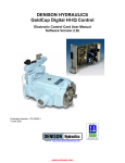
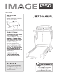
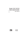
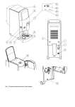
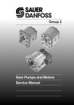
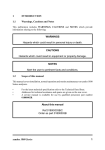
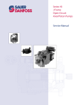
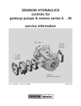
DENISON HYDRAULICS
axial piston variable displacement
worldcup series
LT1-00059-1 Replaces 1-AM012-C
E-Mail: [email protected]
Internet: http://www.denisonhydraulics.com
DATA
TYPICAL CHARACTERISTICS
Specification
Term
Series 6
Series 7
Series 8
in.3/rev.
cm3/rev
6
(98)
7.25
(119)
8.0
(131)
¥ pressure continuous,
max.
psi
bar
5000
(345)
5000
(345)
3600
(250)
¥ intermittent max.
psi
bar
6000
(414)
6000
(414)
4500
(310)
¥ speed, maximum
rev/min
3000
3000
2100
¥ at ÒOÓ inlet
rev./min
2050
1950
1800
¥ case pressure
continuous, max.
psi
bar
75
(5,17)
75
(5,17)
75
(5,17)
¥ intermittent
psi
bar
125
(8,6)
125
(8,6)
125
(8,6)
¥ compensator adjustment:
approx. per turn
psi
bar
2000
(138)
2000
(138)
2000
(138)
¥ max. volume adjustment,
zero to full stroke turns
screw
handwheel
10
16
10
16
10
16
¥ min. compensator
pressure
psi
bar
150
(10)
150
(10)
150
(10)
¥ max. inlet pressure
psi
bar
150
(10,4)
150
(10,4)
150
(10,4)
¥ mounting standard, 4 bolt
SAE
152-4
(D)
152-4
(D)
152-4
(D)
¥ compensator response*
off stroke
on stroke
sec
sec
0.100
0.150
0.100
0.150
0.100
0.150
lb. in2
kg. m2
92
(0,027)
92
(0,027)
92
(0,027)
¥ weight
lbs.
kg.
180
(81)
180
(81)
180
(81)
¥ port A (inlet)
SAE code 61 split flange
in.
mm
2-1/2
(62,5)
2-1/2
(62,5)
2-1/2
(62,5)
¥ port B (system)
SAE code 62 split flange
in.
mm
1-1/4
31,25
1-1/4
31,25
1-1/4
31,25
¥ port D,D1 (case drain)
SAE
-16
-16
-16
¥ port LS (load sensing port)
SAE
-4
-4
-4
¥ port V (compensator vent)
SAE
-6
-6
-6
¥ port X (rotary servo)
SAE
-6
-6
-6
¥ port E, H (rotary servo)
(electric & hydraulic
stroker inlet)
SAE
-4
-4
-4
¥ port RV (cylinder relief port)
SAE
-4
-4
-4
¥ displacement (theoretical)
zero (bar)
¥ rotating inertia
FLUID CONNECTIONS
* For primary compensator control without limiting orifice
NOTE: New revisions are shown underlined. Pages are marked revised
where changes have been made.
2
INTRODUCTION
GENERAL
The Denison Hydraulics Worldcup 6, 7, and 8 axial piston pumps feature advance
design concepts which are time proven and provide for advance pumping and control
concepts.
DESCRIPTION
The main rotating group is the same as in the Goldcup hydrostatic transmissions that
have been in service for more than 24 years.
Standard control for the Worldcup units is a pressure Compensator. Additional optional
controls are also available.
ADJUSTABLE
VOLUME STOP
CENTRAL SHOE
HOLDDOWN SYSTEM
CONTROL
PISTON
SHAFT
BEARING
MOUNTING
BARREL
BEARING
This pump is designed to operate in any position. The mounting hub and four bolt
mounting flange are in full conformance with SAE standard. The pump shaft must be
in alignment with the shaft of the source driver and should be checked with a dial indicator. The mounting pad or adapter into which the fluid pump pilots must be concentric
with the pump shaft to prevent bearing failure. This concentricity is particularly important if the shaft is rigidly connected to the driving load without a flexible coupling.
SAE
Size
Rear Drive
Coupling*
Part No.
Max. Torque
In. Lbs.
Rear Seal
O-ring ARP
B
031-57170
1852 (209 Nm)
00155
BB
031-57171
2987 (338 Nm)
00155
C
031-57190
See below
00159
D
031-57191
See below
00163
*Coupling mate with SAE splined shafts, flat root side fit, SAE J498B (1971) Class 1.
For C and D rear drives, the maximum torque that may be taken from the rear drive is
9,000 In. Lbs. (1017 Nm), IF this does not result in a total torque on the main shaft in
excess of 11,000 In. Lbs. (1243 Nm). Example: P7W at 5000 PSI (345 bar) and full
displacement requires 5770 In. Lbs. (652 Nm). Thus it can then drive a rear torque
load up to 5230 In. Lbs. (590 Nm) maximum. If the P7W will never exceed 500 PSI
(577 In. Lbs., 65 Nm) then the maximum rear torque is 9,000 In Lbs. (1017 Nm).
Caution: The shaft and seal area of a rear mounted pump will be exposed to the primary pumpÕs case pressure. This can cause damage to the rear mounted pumpÕs shaft
seal. For a rear mounted pump without external drain, modification of the pumpÕs shaft
seal will be required if case pressure exceeds that which the rear seal can withstand. If
the rear mounted pump contains a case drain, the primary and the rear mounted pump
case drains may be connected to a common line to equalize the pressures on the
shaft seal.
The product information, specifications, and descriptions contained in this publication have been
compiled for the use and convenience of our customers from information furnished by the manufacturer; and we can not, and do not, accept any responsibility for the accuracy or correctness
of any description, calculation, specification, or information contained herein. No such description, calculation, specification, or information regarding the products being sold has been made
part of the basis of the bargain, nor has same created or amounted to an express warranty that
the products would conform thereto. We are selling the goods and merchandise illustrated
and described on this publication on an "as is" basis, and disclaim any implied warranty,
including any warranty of merchantability or warranty of fitness for any particular purpose
whatsoever, with respect to the goods and merchandise sold. All manufacturer warranties
shall be passed on to our customers, but we shall not be responsible for special, indirect, incidental, or consequential damages resulting from the use of any of the products or information
contained or described on this publication. Further, we reserve the right to revise or otherwise
make product improvements at any time without notification.
3
HYDRAULIC FLUIDS
Shaft options:
SAE-D splined and keyed, see installation drawing for details.
Shaft Information
Splined: The shafts will accept a maximum misalignment of 0.006Ó TIR (0,15 mm).
Angular misalignment at the male and female spline axes must be less than ±.002 (0.5
mm) per one inch (25.4mm) radius. The coupling interface must be lubricated. Denison
Hydraulics recommends lithium molydisulfide or similar grease. The female coupling
should be hardened and must conform to SAE-J498B (1971) Class 1 flat root side fit.
Keyed: High strength heat treated keys must be used. Replacement keys must be
hardened to 27-34 Rc. The key corners must be chamfered .030Ó-.040Ó (.75-1 mm) at
45¡ to clear radii that exist in the keyway.
Side Load Capability
Both types of shafts will accept a side load of 875 lbs. (396 Kg.) at the center of the
spline or key, with a B10 life of 10,000 hours at 1800 RPM.
Connect inlet and outlet lines to the port block of the pump. The fluid connections are
Inlet: 2-1/2Ó (62.5 mm), 3000 PSI (207 bar), SAE 4 bolt flange, Code 61
Outlet: 1-1/4Ó (31.25 mm), 6000 PSI (414 bar), SAE 4 bolt flange, Code 62
Other: SAE straight thread, O-ring seal.
Piping
See installation drawing for size.
The maximum case pressure is 75 PSI(5,17 bar) continuous, 125 PSI (8.6 bar) intermittent. Case pressures must never exceed inlet pressure by more than 25 PSI (1,7
bar). When connecting case drain line make certain that drain plumbing passes above
highest point of the pump before passing to the reservoir. If not, install a 5 PSI (0,3
bar) case pressure check valve to be certain the case is filled with oil at all times.
The case leakage line must be of sufficient size to prevent back pressure in excess of
75 PSI (5.7 bar) and returned to the reservoir below the surface of the oil as far from
supply suction as possible. All fluid lines, whether pipe, tubing, or hose must be adequate size and strength to assure free flow through the pump. An undersize inlet line
will prevent the pump from reaching full speed and torque. An undersized outlet line
will create back pressure and cause improper outlet operation. Flexible hose lines are
recommended. If rigid piping is used, the workmanship must be accurate to eliminate
strain on the pump port block or to the fluid connections. Sharp bends in the lines
must be eliminated wherever possible. All system piping must be cleaned with solvent
or equivalent before installing pump. Make sure the entire hydraulic system is free of
dirt, lint, scale, or other foreign material.
Caution: Do not use galvanized pipe. Galvanized coating can flake off with continued
use.
SERVICE INFORMATION
4
These hydraulic products are designed to give long dependable service when properly
applied and their systems properly maintained. These general instructions apply to typical systems. Specific instructions for particular equipment can be developed from
them. Refer to bulletin S1-AM012.
CONTROL OPTIONS
RECOMMENDED FLUIDS
See DENISON Hydraulics bulletin SPO-AM305 for more information.
MAINTENANCE
This pump is self-lubricating and preventative maintenance is limited to keeping system fluid clean by changing filters frequently. Keep all fittings and screws tight. Do not
operate at pressures and speeds in excess of the recommended limit. If the pump
does not operate properly, check the Trouble Shooting Chart before attempting to
overhaul the unit. Overhauling may be accomplished by referring to the Disassembly,
Rework of Wear Parts and Assembly Procedures in service manual S1-AM012.
FLUID CLEANLINESS
Fluid must be cleaned before and continuously during operation by filters that maintain
a cleanliness level of NAS 1638 Class 8. This approximately corresponds to ISO
17/14.
5
CONTROL OPTIONS
PRIMARY CONTROLS
Compensator ControlÑ
Code C
The compensator control is located in the cover assembly, it consists of a compensator spool and a pilot-head. It is redesigned for ÒLow Flow.Ó
The stroking cylinder is connected to the output port of the compensator spool. The
compensator pressure port is internally connected to the discharge port of the pump
and the tank port is internally connected to the case drain. The compensator pressure
is set at the pilot-head by an adjustment spring.
When the pump operating pressure is below the compensator setting, springs push
the stroking piston and the hanger to full stroke. The stroking cylinder is connected to
the case drain via the compensator spool.
When the pump operating pressure reaches the compensator pressure setting, the
pilot-head opens and a pressure drop is created over the orifice, causing the compensator spool to move against the spring force, directing pump discharge pressure to the
stroking cylinder. The pump will destroke to maintain set pressure.
When the pump operating pressure decreases below the compensator setting, the
pilot head will close and the compensator spool will move under spring force to its offset position, connecting the stroking cylinder to case. The springs will move the
stroking piston to full displacement again.
The compensator can be remotely controlled via the vent connection, which also
allows for a load sensing circuit. Minimum compensating pressure or vented pressure
is approximately 150 psi (10,3 bar).
Note: Use a 0.040 (1mm) orifice in vent line to prevent flooding the compensator during sensing mode.
C10
6
CONTROL OPTIONS
Rotary Servo ControlÑ
Code R
The rotary servo control consists of a four-port rotary servo which directs servo pressure from an external source to the top stroking cylinder or the bottom stroking cylinder. It requires 1 GPM (4 L/min) servo flow at a pressure of 300 psi (21 bar). Normal
recommended servo pressure of 300 psi (21 bar) with a maximum pressure of 1000
psi (70 bar). Response can be increased by adding more flow under higher pressure.
The servo shaft takes a torque of 5-10 lbs-in (0.5-1 Nm) to rotate at 300 psi (21 bar)
servo pressure. If we turn the rotary servo shaft counterclockwise, servo pressure port
ÒAÓ is connected with the top cylinder port ÒBÓand the bottom cylinder port ÒCÓ is connected with drain port ÒDÓ. This means the stroking piston will move down, causing the
hanger to turn counterclockwise, reducing the displacement . The rotary servo moves
Òzero to ÒfullÓ angle approximately 38 degrees.
As it moves the hanger will move the rotary servo sleeve counterclockwise until the
servo pressure port ÒAÓ is closed again by the rotary servo shaft, thus cancelling the
input signal after the commanded angle has been followed-up by the stroking mechanism.
Note: this control requires a minimum servo pressure of 300 psi (21 bar) above case
pressure. This must be supplied by the customer or via a rear driven pump.
Stroke Speed Table
Pressure
Servo
System
300 psi
(21 bar)
300 psi
(21 bar)
Stroke
On
500 psi 1.0 Second
(34.5 bar)
5000 psi 0.6 Second
(345 bar)
Off
0.60 Second
0.86 Second
R40
7
CONTROL OPTIONS
Electrohydraulic Stroker ControlÑ
Code E
This electrohydraulic control actuates the rotary input shaft by means of a hydraulic
position. In the zero current condition the jet pipe is centered over the two receiver orifices and generates equal pressure in each receiver. The jet pipe is held in this position by the feedback spring from the piston and the null adjust spring which counter
each other and result in a net force of zero on the jet pipe. Assume the current is
increased in a polarity that causes the jet pipe to move to the right. This will cause the
pressure to increase on the right receiver and fall in the left receiver. Since these pressures are communicated to opposite ends of the piston it will move and in turn move
the rotary servo through the arm connecting the piston and rotary servo shaft. The
feedback spring is also connected to the arm which continues to move until the force
balance re-centers the jet pipe. Thus a new steady state condition is achieved. The
control shaft can be manually operated without servo pressure applied to the jet pipe.
Spring centering is also available to center the pump when servo pressure is removed
from the servo control. Note: The electrohydraulic control cannot be used if water
glycol, phosphate ester, or invert emulsions fluids is used in the system. Note:
This control requires a minimum servo pressure of 300 psi (21 bar) above case pressure. This must be supplied by the customer or via a rear drive pump.
E40
Hysteresis: Less than 5%.
Linearity: Within 5%.
Response: 0.5 seconds from zero to full displacement.
Threshold: Less than 2% outside dead band.
Repeatability: Within 2%.
Temperature Null Shift: Less than 2% per 100¡F(38¡C).
Pressure Null Shift: Less than 2% per 500 psi (35 bar).
Neutral Deadband: 0% or 10% of full current.
Pressure Input: Externally supplied by customer to servo inlet port from any source
8
CONTROL OPTIONS
with 400 psi (28 bar) nominal pressure. Pressure range acceptable is 200 to 1000 psi
(14 to 70 bar) above pump case pressure.
Coil Resistance: 24 to 30 ohm.
Electrical Input: 275 mA typical to stroke pump over full 19¡ cam angle, 400 mA
maximum. Current source should have at least a 12V DC capability. Absolute maximum current should be limited to 600 mA to avoid damage to coil. Adjustable displacement stops are provided to mechanically limit the stroke to less than maximum.
Note: Control pressure for this control must be provided by the customer or via a rear
driven control pump.
Fluid Type: Any fluid compatible with the seals and pump may be used.
SEE* BELOW
See Denison Hydraulics bulletin SPO-AM305 for fluid recommendations.
Fluid Cleanliness: This control is capable of passing particles up to 200 Micron in
size. It contains a 75 Micron Òlast chanceÓ filter screen built into the body. See page 5
for cleanliness specifications.
Jupiter Controls: (used to control the ÒEÓ Stroker)
Driver cardÑS20-11712
Options cardÑS20-11716
Power supplyÑS20-11715
Euro card holderÑ701-00007-8
Comments: The control may be manually overridden only if the external pressure
source is disconnected or shut off. A torque of approximately 20 lbs-in (2.3 Nm) is
required to rotate the shaft with external pressure disconnected. Do not exceed 100
lbs-in (11 Nm). Adjustable max. volume stops are included and may be adjusted from
0Ñ19¡.
Note: If the Driver uses Pulse Width Modulation (PWM) the frequency must be 2000
Hz or higher.
*Water glycol, Phosphate Ester, or Invert emulsions including ÒSkydrolÓ are fluids that cannot be used with electrohydraulic control.
CURRENT (Ma)
D
ea
db
an
d
STROKE
100%
0
275 mA Typical
35 mA Typical
+ A
CURRENT (Ma)
100%
0 mA
9
STROKE
Ò0
ÓD
ea
db
a
nd
-
0
250 mA Typical
B
With current polarity
shown, servo shaft will
rotate CCW. Reversal
will rotate shaft CW.
CONTROL OPTIONS
Hydraulic Stroker ControlÑ
Code H
This control actuates the rotary input shaft by means of a hydraulic piston, which is
pressurized by an external pressure source. The piston is biased with a spring, which
provides zero displacement. When the external pressure is introduced into one of the
control ports, the piston exerts a force on the springs. When this force exceeds the
precompression force of the spring, the piston begins to move, rotating the rotary
servo shaft in proportion to pressure. Removing or reducing the input pressure allows
the spring to move the servo shaft back toward the zero displacement position.
H40
Hysteresis: Less than 3%
Linearity: Within 2%
Pressure Input: Control pressure may be from any suitable external source.
Comments: The control may be manually overridden if the external pressure source is
disconnected. Do not exceed 100 lbs-In (11Nm) torque on servo shaft in manual
mode. Adjustable max. volume stops are included.
Note: Control pressure for this control must be provided by the customer or via a rear
driven control pump.
Fluid type: Any fluid compatible with the seals and pump may be used.
see Denison Hydraulics bulletin SPO-AM035 for fluid recommendations.
Fluid Cleanliness: See page 5
Stroke vs Control Pressure
(Other pressure ranges available)
10
CONTROL OPTIONS
Load Sensing Compensator
Code L
The compensator has a separate load sensing port with an isolation valve between the
spool and the load sense port, so that the load sense port sees zero flow. The vent
port is still available and can be used for remote control purposes. When used as a
load sense compensator, the added valve bypasses the flow from the spool to the
case of the pump, rather than allowing it to pass out the load sense port. In this way,
the external load sensing valves see no flow and there is no associated pressure drop,
so they become a pure pressure control.
L10
11
CONTROL OPTIONS
This control is a combined compensator and torque limiter, or, if used as an override, it
is a combined compensator override and torque limiter override. The torque limiter
control valve is mechanically driven by the pump rocker cam to provide the proper
pressure vs. flow relationship to give constant torque. This valve operates in parallel
with the standard compensator valve and controls the displacement of the pump
through the compensator as a function of pressure.
Torque LimiterÑ
Code T
The torque limiter control used as the primary control on the pump provides both pressure compensator functions and torque limiting functions.
T10
PRIMARY CONTROL OPTIONS
Maximum Volume Screw ControlÑ
Code 1
Screw control is similar in action to the handwheel control described in the following
paragraph where-in the adjustment is made by raising or lowering the maximum volume stops to regulate pump delivery.
Maximum Volume Handwheel Control
Code 2
This control provides a means of manually setting the maximum volume delivered by
the pump. Setting is made by use of the the handwheel which positions the cam plate
in the desired position.
Maximum and Minimum Volume
Stops for the Control Codes ÒRÓ,
ÒHÓ, and ÒEÓ OnlyÑ
Code 4
The maximum and minimum stops limit the angle of the rotary servo shaft, replacing
the Code 1 or Code 2 stops. These stops are fully adjustable and are located in the
control cover assembly.
12
CONTROL OPTIONS
SECONDARY CONTROL
OPTIONS
Pressure Compensator OverrideÑ
Code P
The pressure compensator override is an optional control, used when needed with the
rotary, electrohydraulic or hydraulic servo strokers.
In this control the stroking cylinder is spring offset to the zero position. It has the same
rotary servo described previously, but in addition, a cover assembly containing the
compensator override on the opposite side of the pump. The compensator override
control is similar to the compensator control as described before, except the override
path to the top stroking cylinder is provided with a check valve and orifice to limit the
losses from the top stroking cylinder. The bottom stroking cylinder is interconnected to
the rotary servo port ÒCÓ but plugged-off from the compensator override.
If the pump operating pressure reaches the compensator pressure setting, discharge
pressure is directed to the top stroking cylinder. This causes the stroking piston and
hanger to destroke, and the rotary servo sleeve to turn counterclockwise. Now servo
pressure is connected via port ÒPÓ and port ÒC1Ó to the bottom stroking cylinder and
port ÒC2Ó and port ÓTÓ connecting the top stroking cylinder to case, ready to upstroke to
the commanded position, as soon as the operating pressure falls below the override
setting.
R4P
13
CONTROL OPTIONS
SECONDARY CONTROL
OPTIONS
WARNING: Whenever a primary control ÒRÓ, ÒHÓ, or ÒEÓ is used with secondary control
ÒPÓ or ÒTÓ, where the pump will not be allowed to go to zero stroke, the installation of a
special control piston cap must be used where a relief valve can be fitted to insure the
pressure cannot reach system pressure ÒPÓ. The relief valve shall be set to 1000 psi,
69 bar. The cap shall contain a flow limiting orifice (0.031Ó, 0,79 mm), to limit the
amount of oil escaping through this relief valve.
This orifice will limit the speed of compensator response both off-stroke and on-stroke,
therefore a system relief valve is necessary to limit system pressure, and possibly an
accumulator to maintain pressure during times of rapidly increasing demand.
flow limiting orifice
Customer supplied
relief valve and
piping. Set 1000
psi, 69 bar.
R4P with control relief valve and limiting orifice, for stop
set above zero stroke
14
CONTROL OPTIONS
Torque Limiter OverrideÑ
Code T
This option can be used as an output control with a rotary servo, hydraulic stroker or
electrohydraulic stroker or electrohydraulic stroker as an override when both pressure
compensator and torque limiter overrides are available.
WARNING: Whenever a primary control ÒRÓ, ÒHÓ, or ÒEÓ is used with secondary control
ÒPÓ or ÒT,Ó where the pump will not be allowed to go to zero stroke, the installation of a
special control piston cap must be used where a relief valve can be fitted to insure the
pressure cannot reach system pressure ÒPÓ. See circuit on page 14.
R4T
15
PERFORMANCE CURVES
SERIES 6
U.S. DATA
16
PERFORMANCE CURVES
SERIES 6
METRIC DATA
17
PERFORMANCE CURVES
SERIES 7
U.S. DATA
18
PERFORMANCE CURVES
SERIES 7
METRIC DATA
19
PERFORMANCE CURVES
SERIES 8
U.S. DATA
20
INLET PORT
ORDERING CODE
Model number sheet
World Cup pumps
Example model code:
Revised 6/24/02
P
6
W
-2
R
1
*
-C
0
0
-BB
0
Pump
P
Displacement
6.00 cu.in./rev. (98 cc/rev.)
6
7.25 cu.in./rev. (119 cc/rev.)
7
8.00 cu.in./rev. (131 cc/rev.)
8
Type
Standard version
W
Test stand version
T
Shaft
Splined SAE-D (for W type pumps only)
-1
Keyed SAE-D (for W type pumps only)
-2
Splined AND-10266 (for T type pumps only)
-3
Rotation
Clockwise
R
Counter-clockwise
L
Seals
Nitrile (Buna N)
1
EPR (not available when using "E" primary control)(pump will be unpainted unless otherw 4
Flourocarbon (Viton)
5
Military specification MIL-P-25732
6
*
Des ign let t er (assigned by manufacturer)
Primary controls
Compensator
-C
Load sensing compensator (50 PSI pressure drop)
-L
Load sensing compensator (200 PSI pressure drop)
-M
Rotary servo
-R
Torque limiter
-T
Hydraulic servo
-H
Electro-hydraulic servo
-E
Primary control options
None (for C, L, M, R, & T primary controls only)
0
Maximum volume screw (for C, L, M, & T primary controls only)
1
Maximum volume handwheel (for C, L, M, & T primary controls only)
2
Remote access volume adjustment (for C & T primary controls only)
3
Maximum & minimum volume adjustment (for R, H, & E primary controls only)
4
Secondary controls
None
0
Compensator override (for R, H, & E primary controls only)
P
Torque limiter override (for R, H, & E primary controls only)
T
Note: Whenever P or T are chosen, if you have an application where the pump will not be allowed to go to zero stroke,
the installation of a special control piston cap must be used so that a relief valve can be fitted to ensure the pressure
cannot reach system pressure. See circuit on page 14 of sales catalog.
External drive
None
-0
SAE-B (SAE 101-2) with SAE-B (SAE 22-4) coupling
-B
SAE-B (SAE 101-2) with SAE-BB (SAE 25-4) coupling
-BB
SAE-C (SAE 127-4) with SAE-C (SAE 32-4) coupling
-C
SAE-D (SAE 152-4) with SAE-D (SAE 44-4) coupling
-D
External mounting
No external pump mounted
External pump mounted (requires special modification "-M2")(must be separately specified)
Special modification
None
No paint
Other special modification (example: tandem pumps)
Allowable controls
C00,C10,C20,C30,L00,L10,L20,M00,M10,M20
T00,T10,T20,T30,R00,R40,R0P,R4P,R0T,R4T
E40,E4P,E4T,H40,H4P,H4T
32
0
1
omit
-NP
-M2
CONVERSIONS & FORMULAS
DEFINITION & UNIT
displacement
in3/rev x 16.387 = cm3/rev
cm3/rev x 0.06102 = in3/rev
flow
gpm x 3.78 = L/min
L/min x 0.2642 = gpm
power
hp x 0.7457 = kW
kW x 1.341 = hp
torque
lb-ft x 1.3567 = Nm
Nm x 0.7376 = lb-ft
2
pressure
lbs/in (psi) x 0.06895 = bar
lbs/in2 (psi) x 6.895 = kPa
bar x 14.50 = lbs/in2 (psi)
kPa x 0.1450 = lbs/in2 (psi)
weight
lb x 0.4536 = kg
kg x 2.205 = lbs
force
lb x 4.448 = N
N x 0.2248 = lbs
volume
in3 x 16.387 = cm3
cm3 x 0.06102 = in3
area
in2 x 6.452 = cm2
cm2 x 0.1550 = in2
length
in x 25.4= mm
mm x 0.03937 = in
temperature
degree F-32 = °C
1.8
cSt x 1.0 = mm2/sec
SSU ;
= cSt x 4.25 + 14
1.8 x (°C+32) = ° F
viscosity
mm2/sec x 1.0 = cSt
20 cSt ;
= 99 SSU
FLUID POWER FORMULAS
Pump input torque
lbs. in.
Pump input power
hp
pressure(psi) x displacement (in3/rev)
2p x mech. eff.
rpm x (in3/rev) x (psi)
395934 x overall eff.
Pump output flow
U.S. gpm
Fluid motor speed
rpm
Fluid motor torque
lbs. in.
Fluid motor power
hp
(metric)
Pump input torque
Nm
pressure(bar) x displacement (cm3/rev
20p x mech. eff.
Pump input power
kW
rpm x (cm3/rev) x (bar)
600000 x overall eff.
Pump output flow
Lpm
Fluid motor speed
rpm(min-1) (tr/mn)
Fluid motor torque
Nm
pressure(bar) x displacement (cm3/rev) x mech. eff.
20p
Fluid motor power
kW
rpm x (cm3/rev) x (bar) x overall eff.
600000
33
rpm x (in3/rev) x volumetric eff.
231
231 x flow rate(U.S. gpm) x volumetric eff.
displacement (in3/rev)
pressure(psi) x displacement (in3/rev) x mech. eff.
2p
rpm x (in3/rev) x (psi) x overall eff.
395934
rpm x (cm3/rev) x volumetric eff.
1000
1000 x flow rate (Lpm) x volumetric eff.
displacement (cm3/rev)
NOTES
34
Sales & Service Locations Worldwide
Denison Hydraulics Inc
14249 Industrial Parkway
Marysville, OH 43040 USA
Tel :........................... 937-644-3915
Fax :.......................... 937-642-3738
E-mail:
[email protected]
Call toll-free
800-551-5956
in North America or
visit
www.denisonhydraulics.com
to locate a
Denison representative
nearest you.
Asia-Pacific
Europe
Australia
Austria
Denison Hydraulics PTY
41-43 St Hilliers Road
P.O.Box 192
Auburn N.S.W. 2144, Australia
Tel : +61 (2) 9646 5200
Fax : +61 (2) 9643 1305
Denison Hydraulics GmbH
Zweigniederlassung Linz
Haibachstraße 69
4061 Pasching, Austria
Tel : +43 (72 29) 48 87
Fax : +43 (72 29) 6 30 92
Hong Kong
Benelux
Denison Hydraulics Ltd.
Unit 6A, 33/F Cable TV Tower
9 Hoi Shing Road, Tsuen Wan
NT, Hong Kong
Tel : +852 2498 8381
Fax : +852 2499 1522
Denison Hydraulics Benelux B.V.
Pascalstraat 100
3316 GR Dordrecht, Holland
Tel : +31 (78) 6543 070
Fax : +31 (78) 6175 755
Japan
Denison Hydraulics Denmark A/S
Industrikrogen 2
2635 Ishöj, Denmark
Tel : +45 (4371) 15 00
Fax : +45 (4371) 15 16
Denison Japan Inc.
4-2-1 Tsujido-Shinmachi
Fujisawa 251-0042, Japan
Tel : +81 (466) 35-3050
Fax : +81 (466) 35-2019
People Republic of China
North America
Canada
Denison Hydraulics Canada Inc.
2880 Brighton Road, Unit 1
Oakville, ON L6H 5S3, Canada
Tel : +1 (905) 829-5800
Fax : +1 (905) 829-5805
Latin America
Mexico, Central America, South
America, Caribbean countries
Denison Hydraulics Inc.
7850 NW 146 Street
Suite 512
Miami Lakes, FL 33016, USA
Tel : +1 (305) 362-2246
Fax : +1 (305) 362-6220
Shanghai Denison Hydraulics
Engineering Ltd.
Room 8018, No. 601
Zhang Yang Road,
Pudong New Area
Shanghai 200120, P.R. China
Tel : +86 (21) 58205042 / 34
Fax : +86 (21) 58205014
Singapore
Denison Hydraulics PTE LTD
Blk 4012 Ang Mo Kio Ave 10,
Unit #07-01D Techplace I
Singapore 569628
Tel : +65 268 7840
Fax : +65 268 7847
Taiwan
Denison Hydraulics LTD
6F-10, No. 79,
Sec. 2 Roosevelt Rd,
Taipei, Taiwan, ROC
Tel : +886-2-23645101
Fax : +886-2-23639025
Denmark
Finland
Denison Lokomec Oy
Polunmäenkatu 22
P.O. Box 116
33721 Tampere, Finland
Tel : + 358 (3) 357 5100
Fax : + 358 (3) 357 5111
France
Denison Hydraulics S.A.
14 route du bois blanc
BP 539
18105 Vierzon, France
Tel : +33 (2) 48 53 01 20
Fax : +33 (2) 48 75 02 91
Great Britain
Denison Hydraulics UK LTD
Kenmore Road
Wakefield 41, Industrial Park
Wakefield, WF2 OXE
West Yorkshire, England
Tel : +44 (1924) 826 021
Fax : +44 (1924) 826 146
Germany
Denison Hydraulics GmbH
Auf dem Sand 14
D 40721 Hilden, Germany
Tel : +49 (0) 2103 / 940-3
Fax : +49 (0) 2103 / 940-558
Italy
Denison Hydraulics Srl
Via Le Europa 68
20090 Cusago (MI), Italy
Tel : +39 (02) 90330-1
Fax : +39 (02) 90390694/5/6
Denison Calzoni S.p.A
Via Caduti di Sabbiuno15/17
40011 Anzola dell'Emilia
Bologna, Italy
Tel : +39 (051) 6501611
Fax : +39 (051) 736221
Spain
Denison Hydraulics S.A.
Gomis 1
08023 Barcelona, Spain
Tel : +34 (93) 253 1990
Fax : +34 (93) 211 6507
Sweden
Denison Hydraulics Svenska AB
Sporregatan 13
213 77 - Malmö, Sweden
Tel : +46 (40) 600 13 00
Fax : +46 (40) 600 13 50
Others
Other European, Middle East,
African countries
Denison Hydraulics S.A.
ATTN: Export Office
14 route du bois blanc
BP 538
18105 Vierzon, France
Tel : +33 (2) 48 53 01 20
Fax : +33 (2) 48 53 01 46
Printed in U.S.A. 10-02 HP
For more information, please contact:
http://www.denisonhydraulics.com
Copyright © 2002 Denison Hydraulics Inc. All rights reserved. 4-30-02