1
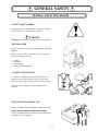
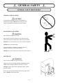
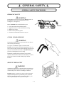
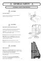
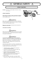
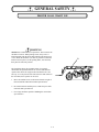
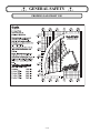
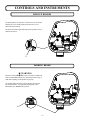
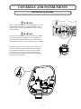
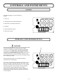
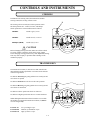
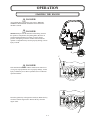
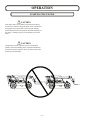
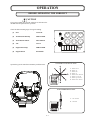
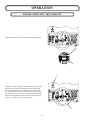
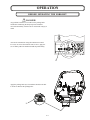
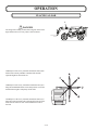
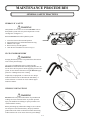
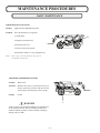
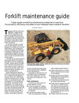
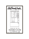
Operator’s Manual GTH-636 with Maintenance Information First Edition Second Printing Part No. 114104 TABLE OF CONTENTS SECTION 1 ROUGH TERRAIN FORK LIFT SAFETY SECTION Introduction Standards And Symbols Safety Training And Knowledge Operator's Responsibilities Management's Responsibilities Maintenance And Repair Operation Safety 1-1 1-3 1-4 1-5 1-5 1-6 1-7 1-8 1-9 SECTION 2 GENERAL SAFETY General Safety Procedures Jump Starting Proper Load Chart Use 2-1 2-3 2-8 2-9 SECTION 3 CONTROLS AND INSTRUMENTS Operator's Compartment Joystick Control Functions Joystick Control Functions (Button Pushed) Service Brakes Parking Brake Frame Sway Control Gauges Hydraulic Pump Destroke Button Steering Transmission 3-1 3-3 3-4 3-5 3-6 3-6 3-7 3-8 3-8 3-9 3-9 SECTION 4 OPERATION Operation And Safety Guidelines Before Starting The Engine Starting The Engine Before Operating The Forklift Transporting A Load Placing A Load 4-1 4-3 4-4 4-5 4-7 4-11 4-13 SECTION 5 MAINTENANCE PROCEDURES General Safety Practices Daily Maintenance 5-1 5-3 5-5 SECTION 6 MATERIAL SAFETY DATA SHEETS 6-1 SECTION 1 ROUGH TERRAIN FORK LIFT SAFETY 1-1 TABLE OF CONTENTS SECTION 1 - ROUGH TERRAIN FORK LIFT SAFETY Introduction 1-3 Standards And Symbols 1-4 Safety 1-5 Training And Knowledge 1-5 Operator's Responsibilities 1-6 Management's Responsibilities 1-7 Maintenance And Repair 1-8 Operation Safety 1-9 1-2 ROUGH TERRAIN FORK LIFT SAFETY INTRODUCTION Owners, Users, and Operators: Genie appreciates your choice of our machine for your application. Our number one priority is user safety, which is best achieved by our joint efforts. We feel that you make a major contribution to safety if you, as the equipment users and operators: 1. Comply with OSHA, Federal, State, and Local Regulations. 2. Read, Understand, and Follow the instructions in this and other manuals supplied with this machine. 3. Use Good Safe Work Practices in a common sense way. 4. Only have trained/certified operators – directed by informed and knowledgeable supervision – running the machine. NOTE: OSHA prohibits the alteration or modification of this machine without written manufacturer's approval. Use only factory approved parts to service or repair this machine. If there is anything in this manual that is not clear or which you believe should be added, please contact us. Internet: www.genieind.com Email: [email protected] Thank you! THIS SYMBOL MEANS YOUR SAFETY IS INVOLVED! READ, UNDERSTAND AND FOLLOW ALL DANGER, WARNING AND CAUTION DECALS ON YOUR ROUGH TERRAIN FORKLIFT. 1-3 ROUGH TERRAIN FORK LIFT SAFETY STANDARDS AND SYMBOLS STANDARDS Many aspects of rough terrain forklift operation and testing are discussed in standards published by the American National Standards Institute. These Standards are updated on a regular basis with addendas. Genie recommends that you purchase and refer to the following standards. ANSI B56.6 – Rough Terrain Fork Lifts This Standard can be purchased from: American National Standards Institute 25 West 43nd Street, 4th Fl. New York, New York, 10036 Tel. 212.642.4900 Fax. 212.398.0023 SYMBOLS The symbols below are used to inform the operator of important information concerning the operation of this machine. DANGER – Indicates an imminently hazardous situation which, if not avoided, will result in death or serious injury. WARNING – Indicates a potentially hazardous situation which, if not avoided, could result in death or serious injury. CAUTION – Indicates a potentially hazardous situation which, if not avoided, may result in minor or moderate injury. ATTENTION – Indicates a situation which, if not avoided, may result in property or equipment damage. 1-4 ROUGH TERRAIN FORK LIFT SAFETY SAFETY These are general safety rules, which must be followed. You are also required to read and understand the Operator's Manual as there are instructions, which are more detailed specific to this machine. TRAINING AND KNOWLEDGE 1. Safety must always be the operator's most important concern. 2. This machine must only be operated by trained personnel, who have demonstrated their ability to do so safely. 3. Comply with the requirements of current Occupational Safety and Health Administration (OSHA) standards, including 29CFR1910.178; and the American National Standards Institute (ANSI) B56.6 latest edition. 4. Read and Understand all Decals and Warnings. 5. Read and Understand the Rating Chart. 6. Know that the machine can safety lift each load before attempting to lift. 1-5 ROUGH TERRAIN FORK LIFT SAFETY OPERATOR'S RESPONSIBILITIES 1. Read and understand the Operator’s Manual. 2. Know the location and the purpose of the controls, instruments and indicator lights. 3. Make sure the machine is in proper order and all operational aids and warning signals are functional before operating. 4. Keep the machine clean, including all instrumentation, windows, lights and other glazed surfaces. 5. Use protective clothing and safety equipment. Always use approved safety equipment such as: gloves, safety boots, hard hats, safety glasses and ear protection where necessary. 6. Wear protective clothing that is snug and belted where required. 7. Store tools and other necessary items in the toolbox. 8. Never lift a load without a Load Rating Chart in the cab. 9. Know the load to be lifted. 10. Be alert, physically fit and free from the influences of alcohol, drugs or medications that might affect the operator’s eyesight, hearing, or reactions. 11. Keep people, equipment and material out of the work area. 12. Keep a fully charged fire extinguisher and first aid kit in the cab at all times, and be familiar with how to use these items. 13. Know about movements of other machinery, trucks and personnel at the jobsite. 14. Make sure everyone is in a safe place before moving the boom, forks, load or outriggers (if so equipped.) 15. Start and stop movements smoothly and swing at speeds that will keep the load under control. 1-6 ROUGH TERRAIN FORK LIFT SAFETY MANAGEMENT'S RESPONSIBILITIES 1. Ensure operators are competent, physically fit, trained and if required licensed. 2. Have a supervisor at the job site to be responsible for job safety. 3. Crew members given specific safety responsibilities and instructed to report any unsafe conditions to the supervisor. 4. Supply the weight on the load to be lifted to the operator. 5. Verify that all crewmembers are familiar with OSHA, ANSI B56.6 requirements as well as instructions in the manuals. 1-7 ROUGH TERRAIN FORK LIFT SAFETY MAINTENANCE AND REPAIR 1. Practice safe maintenance procedures. Perform all maintenance and repairs in accordance with instructions provided by the manufacturer in the manuals. Also heed the warnings on the placards and decals on the machine. 2. Always use supports and braces when working on, under or around the machine or forks. 3. Shut off the engine and lockout the machine while working on the machine unless instructions specifically require the engine to be running. 4. Always make sure the machine is stationary prior to performing adjustments or lubrication. 5. Replace all shields and guards after performing service. 6. Always use a piece of cardboard or paper to search for leaks. 7. When performing work on the hydraulic system: i. ii. iii. iv. v. vi. Lower the boom to horizontal. Support the boom with supports or braces. Shut down the engine. Relieve all pressure before disconnecting lines. Ensure all connections are tight before applying pressure. Repair or replace any damaged line, hose or fitting before applying pressure. 8. Always have tires serviced and mounted by a qualified person with the proper tools and guards. 9. Always use an inflation cage during tire inflation. 10. Only perform welding on the machine with approval from the manufacturer. 1-8 ROUGH TERRAIN FORK LIFT SAFETY OPERATION SAFETY 1. Always inspect the machine daily. Check for leaks, worn hoses, loose belts, broken structures, and loose or missing bolts. Repair or replace any worn, damaged or leaking parts prior to operation of the machine. 2. Only inspect the coolant level when the engine and coolant are cool. 3. Be sure that all guards and screens are secure and in the proper place. 4. Inspect for and clear the work area of any obstructions that could interfere with proper machine operation. Any obstructions that cannot be cleared should be clearly marked and avoided during operation. 5. Refueling: i. Always stop the engine before refueling the machine. ii. Fill the fuel tank outdoors. iii. Handle fuel with care, as it is highly flammable. Do not refuel the machine while smoking or near open flames. iv. Always clean up spilled fuel. 6. Make sure the machine and access system is clean and free of dirt, oil, grease or debris. 7. When getting on and off the machine, face the machine, use the steps and handrails provided, and always maintain a three point contact. 8. Always remain completely inside the cab enclosure while operating the machine. 9. Always wear the seat belt while operating the machine. 10. Always completely lower the boom with the forks resting on the ground before any work is performed on or around the machine. 11. Do not operate the machine while people are under or near an elevated boom whether the boom is loaded or unloaded. Falling objects from the forks or attachment may cause serious injury or death. 1-9 ROUGH TERRAIN FORK LIFT SAFETY OPERATION SAFETY 12. Maintain an appropriate clearance from electrical power lines. See the chart below for minimum safe approach distances. Minimum Safe Approach Distance Power Line Voltage Required Clearance 0 to 50 kV 10 ft. (3.00 m) 50 to 200 kV 15 ft. (4.60 m) 200 to 350 kV 20 ft. (6.10 m) 350 to 500 kV 25 ft. (7.62 m) 500 to 750 kV 35 ft. (10.67 m) 750 to 1000 kV 45 ft. (13.72 m) 13. Lifting Loads: i. Using the load chart, confirm that the load is within the rated capacity of the machine for the required configuration. ii. Level the machine using the level gauge before lifting loads. Use the sway control to level the machine only when the boom is at horizontal or lower. Using the sway control with the boom above horizontal may cause the machine to overturn. iii. Verify that the load is secured on the forks before performing a lift. Rearrange the load if necessary. iv. Before lowering a maximum load, always retract the boom completely. v. Use proper attachments, such as a truss boom, to lift suspended loads. 14. If the load to be lifted exceeds the capacity of the machine for the given configuration: i. Move the machine closer to the load so that the weight of the load will be within the allowable load chart specifications. ii. Divide the load into smaller pieces. iii. Get a larger machine capable of handling the load. 15. Always move a load so that you have maximum machine stability and visibility is not obstructed. Keep the boom at or below horizontal, with the load close to the ground. 16. Tilt the forks back towards the machine slightly during travel to ensure stability of the load. 1 - 10 ROUGH TERRAIN FORK LIFT SAFETY OPERATION SAFETY 17. Inspect the path of travel before beginning movement. Avoid holes and dropoffs. 18. Traveling on slopes/grades. i. Ascend and descend slowly and with caution. ii. When loaded, always travel with the load uphill. iii. When unloaded,travel with the attachment downhill. iv. Avoid turning, travel straight up and down. 19. Always position all wheels in line with the machine before switching the steering mode. 20. Always position the machine and set the park brake before lifting a load. 21. Do not allow riders on the machine or forks. 22. Do not transport or lift personnel into position with this forklift. 23. When leaving the operator's station: i. Place the directional controls in neutral. ii. Apply the parking brake. iii. Lower the attachment to the ground. 1 - 11 ROUGH TERRAIN FORK LIFT SAFETY NOTES 1 - 12 SECTION 2 GENERAL SAFETY 2-1 TABLE OF CONTENTS SECTION 2 - GENERAL SAFETY General Safety Procedures 2-3 Jump Starting 2-8 Proper Load Chart Use 2-9 2-2 GENERAL SAFETY GENERAL SAFETY PROCEDURES SAFETY ALERT SYMBOL Stop and take time to read ALL safety alert messages. Follow all safety messages to avoid injury and/or death. WARNING ALWAYS wear eye protection and personal safety equipment. THE OPERATOR The operator must be fully trained and qualified to operate this machine. Before start-up or machine operation, the operator must learn the location and purpose of the: 1. 2. 3. 4. Controls Instruments Indicator lights Safety and instruction labels ACCIDENT PREVENTION Use protective clothing and safety equipment. Always use approved safety equipment such as: gloves, safety boots, safety hard hats, goggles and ear protection when necessary. Wear protective clothing that is snug and belted where required. FIRE PREVENTION/FIRST AID Install a first-aid kit and fire extinguisher in the operator's cab. KEEP THE FIRST-AID KIT and FIRE EXTINGUISHER properly maintained. Follow the instructions provided with the first-aid kit and fire extinguisher. 2-3 GENERAL SAFETY GENERAL SAFETY PROCEDURES WELDING PRECAUTIONS CAUTION Any unauthorized welding can cause structural failure or possible personal injury. DO NOT weld on any structural member. All unauthorized welding will void the warranty. HAND HOLDS AND STEPS WARNING Slips and falls can cause serious injury. When getting on and off the machine, always maintain a three point contact with steps and hand rails while facing the machine. DO NOT use the steering wheel or any other controls as handrails. NEVER jump on or off the machine. Be careful of slippery conditions on platforms, steps and handrails when getting on and off the machine. ALWAYS shut off the engine before leaving the operator's station. REFUELING WARNING Fires can cause death or severe personal injury. Handle fuel with care. It is highly flammable. DO NOT refuel the machine while smoking or when near open flames or sparks. ALWAYS stop the engine before refueling the machine. Fill the fuel tank outdoors. Prevent fires by keeping the machine clean of trash, grease and debris. ALWAYS clean up spilled fuel. 2-4 GENERAL SAFETY GENERAL SAFETY PROCEDURES HYDRAULIC SAFETY WARNING Hot hydraulic oil can cause severe burns. DO NOT work on the hydraulic system if the oil temperature exceeds 120 degrees F. (49 degrees C). Before ANYONE works on the hydraulic system: 1. 2. 3. 4. 5. A Lower the boom to the horizontal position. Support the boom to avoid unintentional lowering. Shutdown the engine. Remove the key from the ignition. Clean the area around the oil reservoir cap (A). FLUIDS UNDER PRESSURE WARNING Escaping fluid under pressure can penetrate the skin and can cause serious personal injury. Use a piece of cardboard or paper to search for leaks. DO NOT use hands. Before disconnecting hydraulic lines, be sure to relieve all line pressure. Before applying pressure to the system, be sure that all connections are tight. DO NOT apply pressure to a damaged line, hose or fitting. If injured by escaping fluid, see a doctor at once. Proper medical treatment must be administered immediately. A serious infection or reaction can result without proper medical treatment. SERVICE TIRES SAFELY WARNING An improperly mounted over-pressurized tire can result in tire explosion causing possible personal injury. An inflation cage or other safety device must be used during tire inflation. DO NOT attempt to mount a tire unless you have the proper equipment and experience to perform the job. If you do not have the proper qualifications to perform the job have your dealer or qualified repair service perform the repair. 2-5 GENERAL SAFETY GENERAL SAFETY PROCEDURES CAUTION USE SEAT BELT Always wear the seat belt while operating the machine to reduce the risk of personal injury. CAUTION PRACTICE SAFE MAINTENANCE Unauthorized modifications to the machine may impair the safety, machine function and/or affect machine life. ALWAYS use a safety support or brace when working on, under, or around the machine or forks. DO NOT adjust or lubricate the machine while it is in motion. SHUT OFF the engine and LOCKOUT the ignition while working on the machine unless maintenance instructions require the engine to be running. REPLACE all the shields and guards after servicing. NEVER use the machine as a platform for lifting personnel. CAUTION BOOM SAFETY DO NOT enter the DANGER AREA under or around the boom when the forks are off the ground or while the engine is running. (See diagram at right for DANGER AREA). Serious personal injury could result if the boom should unexpectedly drop. Before ANY work is performed in the DANGER AREA the boom must be COMPLETELY lowered and the forks must be resting on the ground. 2-6 GENERAL SAFETY GENERAL SAFETY PROCEDURES AVOID ELECTRICAL POWER LINES DANGER REQUIRED CLEARANCE FOR NORMAL VOLTAGE IN OPERATION NEAR HIGH VOLTAGE POWER LINES AND OPERATION IN TRANSIT WITH NO LOAD AND BOOM OR MAST LOWERED. Normal Voltage, kV (Phase to Phase) Minimum Required Clearance, ft. (m) Operation Near High Voltage Power Lines to 50 Over 50 to 200 Over 200 to 350 Over 350 to 500 Over 500 to 750 Over 750 to 1000 10 (3.05) 15 (4.60) 20 (6.10) 25 (7.62) 35 (10.67) 45 (13.72) Operation in Transit With No Load and Boom Lowered to 0.75 Over 0.75 to 50 Over 50 to 345 Over 345 to 750 Over 750 to 1000 4 (1.22) 6 ((1.83) 10 (3.05) 16 (4.87) 20 (6.10) WARNING Always remain completely inside the cab enclosure while operating the machine. WARNING Never operate this machine under the influence of drugs, alcohol and/or medication which can cause drowsiness. WARNING Never transport or lift personnel into position with this forklift. It is not designed as a personnel lifting device. 12345678 12345678 12345678 12345678 12345678 12345678 12345678 2-7 GENERAL SAFETY JUMP STARTING Location: The battery is located under the fuel tank / battery box cover (A). JUMP STARTING Jump starting at the battery or battery replacement is required when the battery is discharged to the point where the battery will not crank the starter. A WARNING Battery posts, terminals, and related accessories contain lead and lead compounds, chemicals known to the State of California to cause cancer and reproductive harm. Batteries also contain other chemicals known to the State of California to cause cancer. Wash hands after handling. WARNING Never jump start the machine directly to the starter or the starter solenoid. Serious injury or death could result from the machine moving forward or backward. WARNING To avoid personal injury when jump starting with another machine, be certain that the machines are not touching. Never jump start a frozen battery as it will explode. Keep sparks and flames away from the battery. Lead acid batteries generate explosive gases when charging. Wear safety glasses when working near batteries. The booster battery must be a 12 volt type. The machine used for jump starting must have a negative ground electrical system. To jump start the machine, proceed as follows: 1. Connect the positive (+) jumper cable to the positive (+) post of the discharged battery. 2. Connect the other end of the same jumper cable to the positive (+) post of the booster battery. 3. Connect one end of the second jumper cable to the negative (-) post of the booster battery. 4. Make the final cable connection to the engine block or the furthest ground point away from the battery. 5. Start the engine. 6. Remove the jumper cables in the reverse order of their connection (i.e. negative cable ground connection first, etc.) 2-8 GENERAL SAFETY PROPER LOAD CHART USE WARNING NEVER raise a load and drive to position it. This can cause the machine to turnover. When placing a load, always move a loaded machine with the boom angle indicator (B) at 0 degrees or less. When the machine is as close as possible to where the load needs to be placed, set the parking brake, raise the load, then place the load into position. The load chart shows the operating limits of a properly maintained and operated machine. To use the load chart the operator must know the weight of the load and how far "out" and "up" it is to be placed. If the load is heavier than stated on the load chart, three options can be used: 1. Move the machine closer to the load so that the weight of the load will fall within the load chart specifications. 2. Divide the load into smaller pieces so that each piece falls into load chart specifications. 3. Get a larger machine capable of handling the load within specifications. 2-9 B GENERAL SAFETY PROPER LOAD CHART USE 2 - 10 SECTION 3 CONTROLS AND INSTRUMENTS 3-1 TABLE OF CONTENTS SECTION 3 - CONTROLS AND INSTRUMENTS Operator's Compartment 3-3 Joystick Control Functions 3-4 Joystick Control Functions (Button Pushed) 3-5 Service Brakes 3-6 Parking Brake 3-6 Frame Sway Control 3-7 Gauges 3-8 Hydraulic Pump Destroke Button 3-8 Steering 3-9 Transmission 3-9 3-2 CONTROLS AND INSTRUMENTS OPERATOR'S COMPARTMENT 1. Accelerator Pedal 8. Hourmeter 15. Parking Brake Handle 22. Heater Switch 2. Joystick 4-way Controller 9. Gauges 16. Pump Off Button 23. Plug / Turn Signal Wires 3. Transmission Control Lever 10. Machine Level Gauge 17. Windshield Wiper 24. Interior Rear View Mirror 4. Steering Selector 11. Plug / 12 Volt Access. 18. Ignition Switch 25. Frt.Axle Differential Lock (optional) 5. Service Brake Pedal 12. Seat 19. Auxiliary Hydraulics 6. Parking Brake Warning Light 13. Frame Level Switch 20. Steering Wheel 7. Load Chart 14. Seat Belt 21. Headlight Switch 3-3 CONTROLS AND INSTRUMENTS JOYSTICK CONTROL FUNCTIONS A - Boom Down B - Boom Up B A C - Boom Out D - Boom In C D E - Boom Down and Out F - Boom Up and In G - Boom Up and Out H - Boom Down and In 3-4 CONTROLS AND INSTRUMENTS JOYSTICK CONTROL FUNCTIONS (BUTTON PUSHED) A - Tilt Down B - Tilt Back B A 3-5 CONTROLS AND INSTRUMENTS SERVICE BRAKES The brake pedal is the operator's control for the service brakes. Pushing the service brake pedal (A) activates the service brakes for all four wheels. The brakes should be applied during normal operation to stop machine movement. A PARKING BRAKE WARNING Failure to set the parking brake before leaving the machine may result in unintended machine movement and possible injury or death and/or damage to the machine or property. The parking brake should be engaged anytime the operator gets off the machine. To engage the parking brake, move handle (B) to the "BRAKE ON" position. B 3-6 CONTROLS AND INSTRUMENTS FRAME SWAY CONTROL WARNING Always ensure that the machine level indicator (D) is at zero (0) degrees before raising the boom. Raising the boom with an unlevel machine may cause the machine to overturn, resulting in injury or death. FEET 28 METER (8.54) P.O . BO X 790 455 NORTH SUPERIOR A VEN UE BARAGA, M ICH IGAN 49908 PHON E 906-353-6675 FAX 906-353-7543 24 (7.32) 20 16 (6.10) (4.88) 12 12 (3.66) (3.66) 16 20 (4.88) (6.10) 48 BRAKE ON (14.64) 44 (13.42) 40 MA NUFA CTU RER'S RECOM MEN DED CAP ACITY IS PER ANS I B56.6 STABILITY TES TS USIN G S TAN DARD HO MOGENEOUS CUBES 4x4x4 FT. (1.22x1.22x1.22 M ETERS). LOAD CA PACITIES AT 24 INCH (.61 METERS) LOA D CENTER WITH STA NDARD FO RK FRA ME. (12.20) 36 (10.98) 32 (9.76) 28 (8.54) PUMP OFF 24 RATED LIF T CAPACITIES ARE WITH : MACH INE ON A FIRM, LEVEL SURF ACE WITH UND AMAGED, PROP ERLY IN FLATED CALCIU M CHLORIDE SO LUTION FILLED TIRES OR OP TIO NAL FO AM FILLED TIRES. REAR AXLE LO CK-UP EN GAGED. (7.32) 20 LOAD LIMITS / H ORIZO NTA L BOOM LAST FU LLY VISIBLE LETTER RETRACTED = 8,000 LBS (A) LETTER VISIBLE = 6,000 LBS (B) LETTER VISIBLE = 4,000 LBS (C) LETTER VISIBLE = 3,000 LBS (D) LETTER VIS IBLE = 2,000 LBS 0 4 (1.22) P /N 3-1483 28 FEET METER (8.54) 24 20 (7.32) (6.10) 0 4 (1.22) 8 (2.44) 12 16 20 (3.66) (4.88) (6.10) SWAY CONTROL WARNING HEADLIGHT Use the frame sway control to level the machine only when the boom angle indicator is at 0 degrees or less. Using the frame sway control when the angle indicator is more than 0 degrees may cause the machine to overturn, resulting in injury or death. The frame sway control (C) is located on the dash panel. The frame sway control is used in conjunction with the machine level indicator (D) located in the center of the cross support that the interior rear view mirror is mounted on. The sway control switch is either toggled to the left or right depending on the particular requirement. SWAY CONTROL C D 3-7 HEATER RY LICS CONTROLS AND INSTRUMENTS GAUGES The following gauges are used to monitor the machine: 1 - Fuel Level BRAKE ON 2 - Oil Temperature, Powershift Transmission 3 - Oil Pressure, Powershift Transmission 1 2 3 6 5 4 PUMP OFF 4 - Voltmeter 5 - Water Temperature, Engine SWAY CONTROL 6 - Oil Pressure, Engine HEADLIGHT HEATER WIPER AUXILIARY HYDRAULICS HYDRAULIC PUMP DESTROKE BUTTON DANGER Depressing the pump destroke button while operating the machine will cause an immediate loss of hydraulic power, possibly creating a very dangerous situation. Hydraulic functions that will be affected are: FORK TILT, LIFT, BOOM EXTEND and RETRACT, PARKING BRAKE and SWAY. None of these functions will operate as long as the button is depressed. The service brakes will continue to function if the accumulator backup has a sufficient gas charge. The pump destroke button (A) is the black push button switch located on the dash panel. A BRAKE ON PUMP OFF For example, when starting the machine for the first time on a 30 degree F. day, depress the pump destroke button while starting the engine. Continue to depress the button for 15 to 20 seconds after the engine starts. Once the engine is running smoothly, release the button and the hydraulic pump will engage. Depressing the pump destroke button will not be required for all other starts of the day, unless the engine has been allowed to cool completely. 3-8 SWAY CONTROL HEADLIGHT HEATER WIPER AUXILIARY HYDRAULICS CONTROLS AND INSTRUMENTS STEERING In addition to the steering wheel, the machine has another steering control, the steering selector switch. B The steering selector switch (B) is a three-position switch. The three positions are: 4-wheel, 2-wheel , and oblique. Switch positions are selected and function as follows: 4-WHEEL Handle right of center 2-WHEEL Handle directly centered FEET 16 28 24 20 12 METER (8.54) (7.32) (6.10) (4.88) (3.66) P.O. BOX 790 455 NORTH SUPERIOR AVENUE BARAGA, MICHIGAN 49908 PHONE 906-353-6675 FAX 906-353-7543 MANUFACTURER'S RECOMMENDED CAPACITY IS PER ANSI B56.6 STABILITY TESTS USING STANDARD HOMOGENEOUS CUBES 4x4x4 FT. (1.22x1.22x1.22 METERS). LOAD CAPACITIES AT 24 INCH (.61 METERS) LOAD CENTER WITH STANDARD FORK FRAME. RATED LIFT CAPACITIES ARE WITH : OBLIQUE (CRAB) MACHINE ON A FIRM, LEVEL SURFACE WITH UNDAMAGED, PROPERLY INFLATED CALCIUM CHLORIDE SOLUTION FILLED TIRES OR OPTIONAL FOAM FILLED TIRES. REAR AXLE LOCK-UP ENGAGED. Handle left of center LOAD LIMITS / HORIZONTAL BOOM LAST FULLY VISIBLE LETTER RETRACTED = 8,000 LBS (A) LETTER VISIBLE = 6,000 LBS (B) LETTER VISIBLE = 4,000 LBS (C) LETTER V ISIBLE = 3,000 LBS (D) LETTER VIS IBLE = 2,000 LBS 12 (3.66) 16 20 (4.88) (6.10) 48 (14.64) BRAKE ON 44 (13.42) 40 (12.20) 36 (10.98) 32 (9.76) 28 (8.54) PUMP OFF 24 (7.32) 20 0 4 (1.22) P/N 3-1483 FEET 28 24 20 METER (8.54) (7.32) (6.10) 0 4 8 12 (1.22) (2.44) (3.66) SWAY 16 20 (4.88) (6.10) CONTROL HEADLIGHT CAUTION HEATER RY LICS Before changing steering selections, make sure all four wheels are in line. Failure to align the wheels to the proper settings before changing steering positions may cause haphazard steering. This may result in injury to personnel and/or damage to the machine or property. TRANSMISSION The transmission control (C) has one lever that controls both directional and speed requirements. It is located on the left side of the steering column. To shift into Forward gear gently pull the lever toward you and move the lever upward. To shift into Neutral move the lever to the center position. To shift into Reverse gear gently pull the lever toward you and move the lever downward. To shift into a lower speed rotate the lever clockwise. BRAKE ON To shift into a higher speed rotate the lever counter-clockwise. PUMP OFF When shifting the transmission from forward to reverse while the machine is in motion the transmission control (C) must be in 1st or 2nd gear only. Forward / 1st Forward / 2nd Forward / 3rd Low speed/High torque Medium speed/Medium torque High speed/Low torque SWAY CONTROL HEADLIGHT C 3-9 HEATER RY LICS CONTROLS AND INSTRUMENTS NOTES 3 - 10 SECTION 4 OPERATION 4-1 TABLE OF CONTENTS SECTION 4 - OPERATION Operation And Safety Guidelines 4-3 Before Starting The Engine 4-4 Starting The Engine 4-5 Before Operating The Forklift 4-7 Transporting A Load 4-11 Placing A Load 4-13 4-2 OPERATION OPERATION AND SAFETY GUIDELINES WARNING Your safety and the safety of those around you depends upon you using care and judgement in the operation of this equipment. Know the positions and functions of all controls before attempting to operate this machine. All equipment has limitations. Understand the speed, braking, steering, stability, and load chart characteristics of this machine before operating. Read the Operator's Manual and ask questions of your supervisor until you know the machine's limitations. It is very important to read, fully understand, and follow these operation and safety guidelines. 1. DO NOT operate this machine while people are under or near an elevated boom whether the boom is loaded or unloaded. Falling objects from the forks or attachment may cause serious injury or death. 2. ALWAYS remain completely within the cab enclosure while operating this machine. Falling debris can cause serious personal injury or death. 3. NEVER extend a load beyond the load chart band. Machine turn over, component damage, injury or death could occur. 4. ABSOLUTELY NO RIDERS SHOULD BE ALLOWED ON MACHINE OR ATTACHMENTS. 5. NEVER lower a maximum load before retracting it. Machine turn over, component damage, injury or death could occur. 6. INSPECT and clear the working area of any obstructions (rocks, fence, wire, etc.) that could cause machine damage. If obstructions cannot be cleared, mark the obstructions with a stake or other marker that will be clearly visible to the operator. 7. DO NOT check the engine coolant level if the engine has recently been run. Injury could occur from escaping hot pressurized coolant. 8. ALWAYS wear the seat belt when operating this machine. 9. ALWAYS inspect the machine daily. Check for leaks, worn hoses, loose belts, or anything out of the ordinary. Repair and/or replace any worn, damaged or leaking parts immediately. Failure to do so can cause injury or death. 10. CHECK to be sure that all guards and screens are secure and in their proper place. 11. CHECK to be sure that all safety devices such as parking brake, service brake, level gauge, neutral start safety switch, back-up alarm, and horn are functioning properly. Always make sure mirrors are adjusted properly. 12. DO NOT travel on terrain or in dangerous areas that could cause the machine to tip over. 13. DO NOT attempt to start the engine by towing or pushing. Damage to the powershift transmission could result. 14. CARRY A LOAD so that you have maximum machine stability and visibility is not obstructed. 15. ALWAYS level the machine as indicated on the machine level indicator before raising the boom. Raising the boom with an unlevel machine may cause the machine to overturn causing injury or death. 16. USE the frame sway control to level the machine only when the boom position is horizontal or lower. Using the frame sway control when the boom is higher than a horizontal position may cause the machine to overturn causing injury or death. 17. DO NOT depress the pump destroke button while operating the machine. This button should be used only during cold start ups. Depressing the button while operating the machine will cause an immediate loss of hydraulic power that will affect fork tilt, lift, boom extend and retract, sway and all other hydraulic functions. The brakes will continue to function if the accumulator backup has a sufficient gas charge. 4-3 OPERATION BEFORE STARTING THE ENGINE WARNING Before starting the engine, be sure that all daily maintenance items have been performed. See Maintenance section. Walk around the machine and check for any parts that are missing, worn, damaged, or leaking. Repair and/or replace any missing, worn, damaged, or leaking parts. 4-4 OPERATION STARTING THE ENGINE DANGER Any problems discovered in the steps prior to "BEFORE STARTING THE ENGINE" should be corrected before the machine is started. DANGER NEVER attempt to start the machine without being seated in the operator's compartment, the parking brake (B) in the on position and the transmission control (C) in the neutral position. Attempting to start the machine from outside the operator's compartment may result in property damage, serious injury or death. B C DANGER If the machine should start with the transmission control lever (C) in gear, stop operation at once or property damage, serious injury or death may occur. Have a qualified service technician repair the machine. BRAKE ON PU MP OFF SWAY CONTR OL HEAD LIGHT Insert the ignition key in the ignition switch (D). Rotate the key clockwise until the engine starts. Release the key when the engine starts. !"#"$ & ' ()*"#+ P.O. BO X 790 455 NORTH SUPERIOR AVENUE BARAGA, MICHIGAN 49908 PHON E 906-353-6675 FAX 906-353-7543 MANUFACTURER'S RECOMMENDED CAPACITY IS PER ANSI B56.6 STABILITY TESTS US ING STANDARD HOMOGENEOUS CUBES 4x4x4 FT. (1.22x1.22x1.22 METERS). LOAD CAPACITIES AT 24 INCH (.61 METERS ) LOAD CENTER WITH STANDARD FORK FRAME. RATED LIFT CAPACITIES ARE WITH : MACHINE ON A FIRM, LEVEL SURFACE WITH UNDAMAGED, PROPERLY INFLATED CALCIUM CHLORIDE S OLUTIO N FILLED TIRES OR OP TIONAL FOAM FILLED TIRES . REAR AXLE LOCK-UP ENGAGED. LOAD LIMITS / HORIZONTAL BOOM LAST FULLY VISIBLE LETTER RETRACTED = 8,000 LBS (A) LETTER VISIBLE = 6,000 LBS (B) LETTER VISIBLE = 4,000 LBS (C) LE TT ER VISIBLE = 3, 000 L BS (D) L ETT ER V IS IBL E = 2,000 LBS FEET 28 METER (8.54) 24 (7.32) 20 16 (6.10) (4.88) 12 (3.66) 12 (3.66) HEATER RY LICS 16 20 (4.88) (6.10) 48 (14.64) BRAKE ON 44 (13.42) 40 (12.20) 36 (10.98) 32 (9.76) 28 (8.54) PUMP OFF 24 (7.32) 20 0 4 (1.22) P/N 3-1483 FEET 28 METER (8.54) 24 (7.32) 20 (6.10) 0 4 8 (1.22) (2.44) 12 (3.66) 16 (4.88) SWAY 20 (6.10) CONTROL HEADLIGHT HEATER RY LICS D 4-5 OPERATION STARTING THE ENGINE CAUTION If the engine fails to start within 30 seconds release the key, wait at least 2 minutes to allow the starter motor to cool before trying again. If the engine fails to start after four attempts, trouble shoot and correct the problem. DO NOT turn the key if the engine is running. This may cause damage to the starter motor. CAUTION Attempting to start the engine by towing or pushing the machine will result in damage to the powershift transmission and will not start the engine! It also is an unsafe practice that could cause personal injury. ○ ○ ○ ○ ○ ○ ○ ○ ○ ○ 4-6 OPERATION BEFORE OPERATING THE FORKLIFT CAUTION If any gauge reading does not fall within the set tolerances the machine must be repaired before operation. Check the dash mounted gauges for logical readings. (1) Fuel 1/2 to Full BRAKE ON (2) Transmission Oil Temp. 180 F to 200 F (3) Transmission Oil PSI. 240 to 280 PSI (4) Volt 12 to 14 (5) Engine Water Temp. 180 F to 200 F 1 2 3 6 5 4 PUMP OFF SWAY CONTROL (6) Engine Oil PSI 40 to 80 PSI HEADLIGHT HEATER WIPER AUXILIARY LEFT RIGHT HYDRAULICS STABILIZER STABILIZER STANDARD JOYSTICK FUNCTIONS Operate the joystick controller momentarily in all directions. A - Boom B - Boom C - Boom D - Boom E - Boom F - Boom G - Boom H - Boom Down Up Out In Down and Out Up and In Up and Out Down and In BUTTON DEPRESSED FUNCTIONS A - Tilt Forward B - Tilt Back 4-7 OPERATION BEFORE OPERATING THE FORKLIFT Operate the frame sway control (A) momentarily right and left. SWAY CONTROL A C Check the steering operation by turning the steering wheel (B) approximately 1/4 turn in each direction. If the front and rear tires are not aligned properly, straighten the rear wheels with the steering selector valve (C) in the "4 wheel" position. Move the steering selector valve to the "2 wheel" position. Bring the front tires into alignment with the rear tires. Place the steering selector valve back into the "4 wheel" position. !"#"$ & ' ()*"#+ P.O. BOX 790 455 NORTH SUPERIOR AVENUE BARAGA, MICHI GAN 49908 PHONE 906-353-6675 FAX 906-353- 7543 MANUFACTURER'S RECOMMENDED CAPACITY IS PE R ANSI B56.6 STABI LITY TESTS USI NG STANDARD HOMOGENEOUS CUBE S 4x4x4 FT. (1.22x1.22x1.22 METERS). LOAD CAPACITI ES AT 24 INCH (.61 ME TERS) L OAD CENTER WITH STANDARD FORK FRAME. RATED LI FT CAPACI TIES ARE WITH : MACHI NE ON A FIRM, LEVEL SURFACE WITH UNDAMAGED, PROPERLY INFLATED CALCIUM CHLORIDE SOLUTION FILL ED T IRE S OR OPT IONAL FOAM FIL LED TIRES. REAR AXL E L OCK-UP ENGAGED. LOAD LIMI TS / HORIZONTAL BOOM LAST FULLY VISIBLE LETTE R RETRACT ED = 8,000 LBS (A) LET TER VISIBLE = 6,000 LBS (B) LETTE R VISIBLE = 4,000 LBS (C) LETT ER VISIBLE = 3,000 LBS (D) LE TTER VI SIBL E = 2,000 LBS FEET 28 METER (8.54) 16 24 20 12 (7.32) ( 6.10) (4.88) ( 3.66) 12 (3.66) 16 20 (4.88) ( 6.10) 48 (14.64) BRAKE ON 44 (13.42) 40 (12.20) 36 (10.98) 32 ( 9.76) 28 ( 8.54) PUMP OFF 24 ( 7.32) 20 0 4 ( 1.22) P/N 3-1483 FEET 28 METER (8.54) 24 20 (7.32) ( 6.10) 0 4 8 12 (1.22) ( 2.44) (3.66) SWAY 16 20 (4.88) ( 6.10) CONTROL HEADLIGHT HEATER RY LICS B 4-8 OPERATION BEFORE OPERATING THE FORKLIFT DANGER Any problems with the service brakes or the parking brake found while conducting the daily inspection should be corrected immediately. Failure to do so could result in injury or death. Activate the transmission using the transmission control lever (D). As soon as the machine starts to move, apply the service brake pedal. The machine should stop immediately. BRAKE ON PUMP OFF SWAY CONTROL HEADLIGHT D Apply the parking brake (E). The machine should not be able to be driven. Release the parking brake. E 4-9 HEATER RY LICS OPERATION BEFORE OPERATING THE FORKLIFT DANGER Never operate the machine with a faulty backup alarm. Doing so may result in serious injury or death. Place the transmission control lever (A) in reverse. The backup alarm should sound. If it does not sound, have the backup alarm repaired immediately. BRAKE ON PUMP OFF SWAY CONTROL HEADLIGHT A B Check and adjust both the interior rear view mirror (B) and the exterior right hand mirror (C) if required. C 4 - 10 HEATER RY LICS OPERATION TRANSPORTING A LOAD WARNING Transporting a load with the boom extended and the boom angle indicator arrow (D) reading more than 0 degrees could cause a roll over hazard. WARNING At no time should any load be suspended from the forks by use of chains, ropes, straps etc. If a load must be suspended the use of a truss (jib) boom is mandatory. Proper rigging procedures should always be followed. The forks should always be tilted back slightly during transportation to ensure stability of the load. D The load should be kept as low to the ground as possible while traveling. Always move a loaded machine with the boom angle indicator (D) at 0 degrees or less. 4 - 11 OPERATION TRANSPORTING A LOAD WARNING Slower speeds should be used whenever transporting a load. Always bring the machine to a complete stop before reversing the transmission control lever (A). Failure to do so can result in damage to the load, the machine and/or bystanders. BRAKE ON PUMP OFF SWAY CONTROL HEADLIGHT A Always keep the boom retracted to ensure greater stability. Always place the load in the center and completely against the back of the fork frame. By doing so greater stability will result. IMPORTANT: Never attempt to use the forks and/or attachments for prying wedged or frozen loads free. Damage to the load, pallet and/or machine could result. 4 - 12 HEATER RY LICS OPERATION PLACING A LOAD B WARNING Do not sway the machine with the boom angle indicator arrow (B) at more than 0 degrees. By doing so you could cause a roll over hazard which may result in injury or death. DANGER Always apply the parking brake (C) before lifting and/or placing a load. Failure to do so could allow the machine to roll over which may result in injury or death. CAUTION Always bring the machine to a complete stop before applying the parking brake (C). Failure to do so will damage the parking brake disc packs, which may void the axle warranty. C !"#"$ &' ( )*"#+ Before placing a load, the frame should be leveled. This can be done by the use of the switch labeled sway control (D) located on the lower right hand side of the dash panel in front of the operator. P.O. BOX 790 455 NORTH S UPERI ORAVENUE BARAGA, MICHIGAN 4 9908 PHONE 90 6-353- 6675 FAX 906- 353-7543 FEET 28 METER ( 8.54) 24 (7.32) 16 20 (6.1 0) (4.88) 12 (3.6 6) 12 ( 3.66) 16 20 (4.8 8) (6.10) 48 ( 14.64) BRAKE ON 44 ( 13.42) 40 ( 12.20) MANUFACTURER'S RECOMMENDED CAPACI TY I S PER ANSI B56.6 S TABILITY TESTS USI NG STANDARD HOMOGENEOUS CUBES 4x4x4 F T. ( 1.22x1.22x1 .22 METERS) . LOAD CAP ACI TI ES AT 24 I NCH ( .61 METERS) LOAD CENTER WITH STANDARD F ORK F RAME. RATED LI FT CAP ACI TI ES ARE WITH : MACHI NE ON A F IRM, LEVEL SURFACE WITH UNDAMAGED, PROPERLY I NFLATED CALCIUM CHLORIDE SOLUTI ON FILLED TIRES OR OPTIONAL FOAM FI LLED TIRES. REARAXLE LOCK-UP ENGAGED. 36 (1 0.98) 32 (9.76) 28 (8.54) PUM P OFF 24 (7.32) 20 LOAD LI MI TS / HORIZONTAL BOOM LAST FULLY VIS IBLE LETTER RETRACTED = 8 ,000 LBS ( A) LETTER VISI BLE = 6,000 LBS (B) LETTER VIS IBLE = 4, 000 LBS (C) LE TT ER VI SIBL E = 3 ,000 LBS (D) LE T TE R VI SIBL E = 2,000 L BS 0 4 (1.22) P/N 3 -1483 FEET 28 METER ( 8.54) 24 (7.32) 20 (6.1 0) 0 4 (1.22) 8 12 (2.4 4) ( 3.66) 16 20 (4.8 8) ( 6.10) SWAY CONTROL HEADLIGHT HEATER RY LI CS SWAY CONTROL D E Adjust the sway control (D) until the indicator ball on the level gauge (E) is on the 0 degree mark. 4 - 13 OPERATION PLACING A LOAD A DANGER Traveling with a reading of more than 0 degress on the boom angle indicator arrow (A) may cause a rollover hazard. Gradually move the 4-way controller towards the letter (B) to lift the load vertically. Hold the controller back until the required height has been achieved. Gradually move the 4-way controller towards the letter (E) to bring the load DOWN and OUT into final position. Lower the load until the weight is completely off the forks. Gradually move the 4-way controller towards the letter (F) to bring the boom UP and IN. This will bring the forks out of the load. Once the forks are clear of the load the boom can be lowered. 4 - 14 SECTION 5 MAINTENANCE PROCEDURES 5-1 TABLE OF CONTENTS SECTION 5 - MAINTENANCE PROCEDURES General Safety Practices 5-3 Daily Maintenance 5-5 5-2 MAINTENANCE PROCEDURES GENERAL SAFETY PRACTICES BEFORE SERVICING Read the entire Maintenance Procedure Section. Familiarize yourself with all the safety precautions listed in Sections 1 & 2. Pay close attention to all the safety alert symbols. Be sure you understand the procedures detailed in this section. Wear personal protective equipment. Remove rings and jewelry. Move the machine to a safe level work place. Lower the boom and support all raised equipment. Shut down the machine. Remove the key from the ignition. Be careful not to spill fuels and lubricants. Do not fill or refuel the fuel tank while the engine is running or hot. Doing so could cause a fire and/or an explosion. Do not smoke while refueling or working with fuel to avoid a fire and/or explosion. IMPORTANT! Always clean up spilled fuel and/or lubricants to avoid polluting the earth. 5-3 MAINTENANCE PROCEDURES GENERAL SAFETY PRACTICES HYDRAULIC SAFETY WARNING Hot hydraulic oil can cause severe burns. DO NOT work on the hydraulic system if the oil system temperature exceeds 120 degrees F. (49 degrees C.) A Before ANYONE works on the hydraulic system: 1. 2. 3. 4. 5. Lower the boom to the horizontal position. Support the boom to avoid unintentional lowering. Shutdown the engine. Remove the key from the ignition. Clean the area around the oil reservoir cap (A). FLUID UNDER PRESSURE WARNING Escaping fluid under pressure can penetrate the skin and can cause serious personal injury. Use a piece of cardboard or paper to search for leaks. DO NOT use hands! Before disconnecting hydraulic lines, be sure to relieve all line pressure. Before applying pressure to the system, be sure that all connections are tight. DO NOT apply pressure to a damaged line, hose or fitting. If injured by escaping fluid, see a doctor at once. Proper medical treatment must be administered immediately. A serious infection or reaction can result without proper medical treatment. WELDING PRECAUTIONS WARNING DO NOT weld on any structural member. Any unauthorized welding can cause structural failure or possible personal injury. All unauthorized welding or repair procedures will void the machine warranty. Before performing any authorized welding, be sure to disconnect the positive lead from the battery. Properly attach the ground cable of the welder to the frame member that is being welded. Failure to do so can cause electrical system damage. 5-4 MAINTENANCE PROCEDURES DAILY MAINTENANCE SCHEDULED MAINTENANCE Maintenace performed quarterly, annually and every two years must be completed by a person trained and qualified to perform maintenance on this machine according to the procedures found in the service manual for this machine. Machines that have been out of service for more than three months must receive the quarterly inspection before they are put back into service. PERFORM ENGINE MAINTENANCE Refer to engine operator's manual. Check engine oil. Check coolant level. Check engine fan. Open water separator. PERFORM TRANSMISSION MAINTENANCE Refer to the transmission operator's manual. Check transmission oil level. 5-5 MAINTENANCE PROCEDURES DAILY MAINTENANCE CHECK HYDRAULIC OIL LEVEL Location: Sight glass (B). Behind the rear panel. To Check: Move the machine to level ground. Level the frame. B Completely retract the boom. Position the forks level. Lower the boom to the ground. Oil should be visible 1/2 way in sight glass (B). NOTE: Refer to page 5-24 of this manual for the proper oil specifications and capacities. CHECK TIRE FOR PROPER INFLATION Location: Wheel ends. To Check: With the valve stem (C) positioned to the top of the tire, check the tire pressure with the tire cold and a properly functioning air pressure gauge. Setting: 50 PSI. C DANGER All tires require a calcium chloride ballast or an optional foam fill to be operated safely. The loss of ballast can affect the machine's stability and cause a rollover hazard, resulting in damage, injury or death. 5-6 SECTION 6 MATERIAL SAFETY DATA 6-1 TABLE OF CONTENTS SECTION 6 - MATERIAL SAFETY DATA Material Safety Data Sheets 6-3 California Proposition 65 Warnings 6-4 6-2 MATERIAL SAFETY DATA MATERIAL SAFETY DATA SHEETS (MSDS) The Federal Occupational, Safety and Health Administration (OSHA) Standard 29 ctr 1910.1200, and in some cases state and local Right-To-Know laws, may require specific MSDS be available to employees prior to operating this equipment. This may include information on substances contained in the equipment such as antifreeze, brake fluid, battery acid and hydraulic fluid. Genie will provide, at no cost, Material Safety Data Sheets which are applicable to their product line. Simply request them from your local Genie dealer or contact us at: Genie Industries PO Box 97030 Redmond, WA 98073-9730 To ensure a prompt response, please be sure to include your return address and zip code, along with the machine model and serial number. 6-3 MATERIAL SAFETY DATA CALIFORNIA PROPOSITION 65 WARNINGS The following warnings are required on all off road equipment operating in the State of California. If you are operating a Genie in the State of California and do not see the approved warning labels, please contact us for a replacement at no charge. Our address is: Genie Industries PO Box 97030 Redmond, WA 98073-9730 CALIFORNIA Proposition 65 Warning Diesel engine exhaust and some of its constituents are known to the State of California to cause cancer, birth defects, and other reproductive harm. CALIFORNIA Proposition 65 Warning Battery posts, terminals, and related accessories contain lead and lead compounds, chemicals known to the State of California to cause cancer and reproductive harm. Batteries also contain other chemicals known to the State of California to cause cancer. Wash hands after handling. 6-4