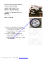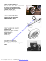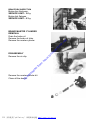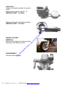
1
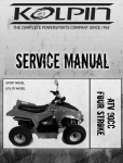
ne t e. im rT .S co ot e w w w m fro d oa de ow nl D PDF 文件使用 "pdfFactory" 试用版本创建 www.fineprint.com.cn § CONTENTS§ PREFACE.....................................................................................Q1-1∼ 1-2 ENGINE REMOVE… … … … … … … … … .................................Q2-1∼ 2-4 ENGINE INSTALLATION......................................................Q 3-1∼ 3-2 im e. ne t LUBRICATION SYSTEM.......................................................Q 4-1∼ 4-2 .S co ot e rT FUEL SYSTEM… … … … … … … … … … … ............................Q 5-1∼ 5-4 w w w CYLINDER HEAD/CYLINDER/PISTON...........................Q 6-1∼ 6-6 fro m TANSMISSION SYSTEM................................… … .............Q 7-1∼ 7-6 ow nl oa de d CRANKSHAFT/CRANKCASE............................................Q 8-1∼ 8-4 D A.C.G. EMERATOR .............................................................Q 9-1∼ 9-2 ELECTRIC SYSTEM............................................................Q10-1∼10-6 CHASSIS… … … … … … … … … … … … … … … … … … … … … … PDF 文件使用 "pdfFactory" 试用版本创建 www.fineprint.com.cn Q11-1~11-2 D ow nl oa de d fro m w w w .S co ot e rT im e. ne t THE CONTENTS OF THIS MANUAL PROVIDE THE SREVICE INFORMATION FOR C.P.I JR50/90. MOST CHAPTERS START WITH A SYSTEM OR ASSEMBLY ILLUSTRATION AND SPECIFICATIONS THE FOLLOWED PAGES GIVE DETAIL PROCEDURES. IF YOU DO NOT KNOW WHAT THE SOURCE OF THE TROUBLE IS, PLEASE GO THE TROUBLESHOOTING FOR ADDITIONAL HELP. ALL THE CONTENTS OF THIS MANUAL ARE BASED ON THE LATEST MODEL INFORMATION C.P.I RESERVE THE RIGHT TO MAKE CHANGE AT ANY TIME WITHOUT NOTICE AND WITHOUT ANY RESPONSIBILITY OR ENGAGEMENT ON OUR PART. PDF 文件使用 "pdfFactory" 试用版本创建 www.fineprint.com.cn Remove the seat & the luggage box. Remove the side covers. .S co ot e rT im e. ne t Remove the luggage box. ow nl oa de d fro m w w w Remover the side cover 2. D 1.Remove the RR Luggage carrier comp. 2.Remove the side covers1. PDF 文件使用 "pdfFactory" 试用版本创建 www.fineprint.com.cn Disconnect the Vacuum hose.1. Disconnect the Fuel hose 1. Disconnect the oil tube. Disconnect the A.C.G wire. Disconnect the start motor wive. Disconnect the throttle valve. .S co ot e rT im e. ne t Disconnect the spark plug cap. ow nl oa de d fro m w w w Disconnect the rear brake cable. D Remove the setting bolt of rear cushion. PDF 文件使用 "pdfFactory" 试用版本创建 www.fineprint.com.cn Remove the setting bolt of engine. D ow nl oa de d fro m w w w .S co ot e rT im e. ne t Remove the engine. PDF 文件使用 "pdfFactory" 试用版本创建 www.fineprint.com.cn ne t e. im rT .S co ot e w w w m fro d oa de ow nl D PDF 文件使用 "pdfFactory" 试用版本创建 www.fineprint.com.cn D ow nl oa de d fro m w w w .S co ot e rT im e. ne t ENGIME INS TALLATION The installation sequence is essentially the reverse of removal. NOTE: Route all the wire and cable properly. Adjust the throttle cable free play. Adjust the oil pump control cable Clearance. Adjust the rear brake free play. PDF 文件使用 "pdfFactory" 试用版本创建 www.fineprint.com.cn OIL PUMP REMOVAL e. im rT .S co ot e D ow nl oa de d fro m w w w Remove the cooling fan cover ,cooling fan ,and A.C.G. Disconnect the oil tube of oil tube of oil. Pump (intake and output). Remove the oil pump control cable. Remove the setting bolt of oil pump. Remove the oil pump. ne t Remove the seat, luggage box, and side covers, PDF 文件使用 "pdfFactory" 试用版本创建 www.fineprint.com.cn Oil pump inspection Check the O-ring, gear & seal for wear or any damage. NOTE: Do not disassembly the oil pump body to prevent any damage. OIL PUMP INSTALLATION ow nl oa de d fro m w w w Connect the oil tube. Connect the oil pump control cable and adjust the clearance. .S co ot e rT im e. ne t Coating some oil the O-ring. Install the oil pump onto the crankcase. D RELEASE THE AIR OF OIL PUMP Loosen the drain screw. Let the oil drain out in smoothly then tight the screw. NOTE: If the oil can not drain out in smoothly, it is mean some air still in the oil pump. PDF 文件使用 "pdfFactory" 试用版本创建 www.fineprint.com.cn THROTTLE VALVE REMOVAL Remove the seat. Remove the luggage box. Loose the carburetor cap. Remove the throttle valve from the carburetor. w w w THROTTLE VALVE DISASSEMBLY Remove the retainer and take out the jet needle clip from the throttle valve. .S co ot e rT im e. ne t Remove the throttle valve from the throttle cable. ow nl oa de d fro m INSPECTION Check the throttle valve and the jet needle surface of dirt, scratches or wear. D CARBURETOR REMOVAL Remove the seat. Remove the luggage box. Remove the side cover. Remove the starter plunger wire. Remove the throttle cable. Remove the fuel tube from the carburetor. Loose the screw of the air cleaner band. Loose the bolts between the intake pipe & the carburetor. Remove the carburetor. PDF 文件使用 "pdfFactory" 试用版本创建 www.fineprint.com.cn Remove the carburetor and let it cool down by nature for thirty minutes. Check the current of air route as show. GOOD : CHECKLESS NG : CHECKED BLOW w D ow nl oa de d fro m w w FLOAT CHAMBER DISASSEMBLY Remove the setting screws. Remove the chamber cap. .S co ot e rT im e. ne t Connect a full charged battery to the starter plunger wore for five minutes. Check the current of route as show. GOOD : CHECKED NG : CHECKLESS Remove the float setting bolt. Remove the float pin. Remove the float. Remove the float valve. PDF 文件使用 "pdfFactory" 试用版本创建 www.fineprint.com.cn BLOW Remove the main jet, slow jet, needle seat & air screw. Clean all the jet & all the hole by using high pressure air. ow nl oa de d fro m w w w CARBURETOR INSTALLATION The installation sequence is essentially the reverse of remove. .S co ot e rT im e. ne t FUEL HEIGHT INSPECTION Measure the height by using a gauge. STANDARD: 18.5 ㎜ D Adjust the clearance of the throttle valve cable. Adjust the air screw. 1 2 STANDARD : 1 ± 1 round 2 Adjust the idle speed. STANDSRD: 1800± 100 rpm PDF 文件使用 "pdfFactory" 试用版本创建 www.fineprint.com.cn REED VALVE REMOVAL Remove the carburetor. Remove the intake pipe. Remove the reed valve. ne t REED VALVE INSPECTION Measure the height of reed valve stopper. STANDARD: 6.0-6.4 ㎜ D ow nl oa de d fro m w w w REED VALVE INSTALLATION The installation sequence is essentially the reverse of removal. .S co ot e rT im e. Check the flatness of reed valve. SERVOCE LIMIT : 10 ㎜ PDF 文件使用 "pdfFactory" 试用版本创建 www.fineprint.com.cn CYLINDER HEAD REMOVAL Remove the seat & the luggage box. Remove the spark plug cap. Remove the exhaust muffler. Remove the side covers. Remove the cylinder air shrouds. w w w ow nl oa de d fro m Cylinder head flatness inspection. SERVICE LIMIT: 0.05 ㎜ .S co ot e rT im e. ne t Remove the spark plug. Remove the setting bolts of cylinder head. Remove the cylinder head. D CYLINDER REMOVAL Remove the cylinder head. Remove the cylinder. Remove the cylinder gasket. NOTE: Clean all the material of cylinder gasket with a scraper. PDF 文件使用 "pdfFactory" 试用版本创建 www.fineprint.com.cn PISTON REMOVAL Remove the piston pin clip. NOTE: Do not let the clip fall into the crankcase. Remove the piston pin. Remove the piston. .S co ot e rT im e. ne t PISTON / PISTON RING INSPECTION Remove the piston rings. Clean the grooves for carbon deposit completely. NOTE: Do not damage the piston ring during removal. ow nl oa de d fro m w w w Cylinder block flatness inspections: SERVICE LIMITS: 0.05 ㎜ D CYLINDER INSPECTION Inspect the cylinder bore for wear or damage. Measure the cylinder I. D. at three places; top, middle and bottom of piston travel and in two directions at right angle to each other. SERVICE LIMITS: 40.2 ㎜ 52.2 ㎜ PDF 文件使用 "pdfFactory" 试用版本创建 www.fineprint.com.cn Calculate the piston-to-cylinder clearance. SERVICE LIMITS : 0.1 ㎜ Calculate the taper and out of round. SERVICE LIMITS: Out of round: 0.05 ㎜ Taper: 0.05 ㎜ .S co ot e rT im e. ne t Measure piston pin bore O. D. at a point 10 ㎜ from the bottom. SERVICE LIMITS: 39.95 ㎜. 51.95 ㎜. ow nl oa de d fro m w w w Measure piston pin bore I. D. in two directions at right angle to each other. SERVICE LIMITS: 10.05 ㎜ 12.05 ㎜ Measure the piston pin O. D. at the front, center and rear and in two directions across from each other. SERVICE LIMIT: 9.95 ㎜ 11.95 ㎜ D Insert each piston ring into cylinder with the piston and measure the ring end gap in the cylinder to a point 10 ㎜ (0.04 in) from the bottom. SERVICE LIMITS: Top / Second: 0.15~0.35 ㎜ PDF 文件使用 "pdfFactory" 试用版本创建 www.fineprint.com.cn Connecting rod small end inspections: SERVICE LIMITS: 14.06 ㎜. 15.06 ㎜. w ow nl oa de d fro m w w NOTE: i Avoid piston and piston ring damage during installation. i All ring should be installed with the mark facing up. .S co ot e rT im e. ne t PISTON RING INSTALLATION Clean the piston ring grooves thoroughly. Install the piston ring. D PISTON INSTALLATION Install the piston, piston pin and new piston pin clips. NOTE: i Piston the “EX” mark on the exhaust side. i Do not let the piston pin clip fall into the crankcase. PDF 文件使用 "pdfFactory" 试用版本创建 www.fineprint.com.cn CYLINDER INSTALLATION Install the cylinder gasket. Coat the cylinder and piston ring with the engine oil. Install the cylinder. .S co ot e rT im e. ne t COMPRESSION PREASURE TEST NOTE: Worm up the engine before test. D ow nl oa de d fro m w w w Remove the seat & luggage box. Remove the spark plug cap & spark plug. Turn the throttle grip with the throttle valve on the upset position. Start the motor for 7-8 seconds for test the pressure STANDARD: 10.0 ㎏/㎝ 2 -600 rpm. PDF 文件使用 "pdfFactory" 试用版本创建 www.fineprint.com.cn LEFT CRANKCASE COVER REMOVAC Remove the start kick. Left crankcase cover and dowel pin. .S co ot e rT im e. ne t Remove the kick pinion with the kick friction spring. Disconnect the kick start spring. Remove the cir-clip,plate washer,kick spindle bush,and spring. ow nl oa de d fro m w w w Remove the setting nut of clutch outer. Remove the clutch outer. Remove the driven pulley and drive beet. D Remove the setting nut of driver face. Remove the conical spring washer and the one way clutch. Remove the claw washer,driver face and plat washer. PDF 文件使用 "pdfFactory" 试用版本创建 www.fineprint.com.cn Remove the movable drive and collar. Remove the starter clutch and starter wheel. Remove the gear boss. Remove the plat washer. Remove the idle gear plate and idle gear. w w w ow nl oa de d fro m WEIGHT ROLLER INSPECTION Measure the weight roller O. D. SERVICE LIMIT : 14.5 ㎜ .S co ot e rT im e. ne t DRIVEN BELT INSPECTION Inspect the belt for crack wear or any damage measure the width of belt. SERVICE LIMIT : 14.6 ㎜ D MOVABLE DRIVEN FACE INSPECTION Measure the movable driven face I. D. SERVICE LIMIT : 17.5 ㎜ 20.5 ㎜ PDF 文件使用 "pdfFactory" 试用版本创建 www.fineprint.com.cn BOSS OF DRIVEN FACE INSPECTION Measure the boss I. D. SERVICE LIMIT : 23.94 ㎜ .S co ot e rT im e. ne t CLUTCH OUTER INSPECTION Measure clutch outer I. D. SERVICE LIMIT : 109.5 ㎜ ow nl oa de d fro m w w w CLUTCH LINING INSPECTION Measure the lining thickness. SERVICE LIMIT : 1.5 ㎜ D DRVIEN PULLEY DISASSEMBLY Fix the driven pulley in a compressor. Remove the special nut (28 ㎜). Release the compressor. Remove the driven plat assy. PDF 文件使用 "pdfFactory" 试用版本创建 www.fineprint.com.cn DRIVEN FACE SPRING INSPECTION Measure the spring free leant. SERVICE LIMIT : 67 ㎜ 89.5 ㎜ w D ow nl oa de d fro m w w MOVABLE DRIVEN FACE INSPECTION Measure the movable drive face I. D. SERVICE LIMIT : 34.06 ㎜ .S co ot e rT im e. ne t DRIVEN FACE INSPECTION Measure the driven face O. D. SERVICE LIMIT : 33.94 ㎜ Final transmission gear removal. Drain the gear oil Remover the mission cover, gasket , and dowel pin. PDF 文件使用 "pdfFactory" 试用版本创建 www.fineprint.com.cn Remove the counter shaft and final shaft. FINAL GEAR TRANSMISSION GEAR INSPECTION D ow nl oa de d fro m w w w .S co ot e rT im e. ne t Inspect the gears and shafts for wear or damage. PDF 文件使用 "pdfFactory" 试用版本创建 www.fineprint.com.cn CRANKCASE REMOVAL Remove the crankcase setting bolts. .S co ot e rT im e. ne t Remove the right crankcase from the left crankcase by using a pulley. ow nl oa de d fro m w w w Remove the crankcase from the left crankcase by using a pulley. D Remove the bearing of crankcase by using a bearing pulley. PDF 文件使用 "pdfFactory" 试用版本创建 www.fineprint.com.cn CRANKSHAFT INSPECTION Measure the connecting rod big end side clearance with a feeler gauge. SERVICE LIMIT: 0.55 ㎜ .S co ot e rT im e. ne t Measure the connecting rod big end radial clearance at two different point across from each other. SERVICE LIMIT: 0.05 ㎜ ow nl oa de d fro m w w w Place the crankshaft on a stand or V-blocks and measure the run out using a dial gauge. Actual bend is 1/2 of total indicator reading. SERVICE LIMIT: 0.1 ㎜ D Check the crankshaft bearing play. If they are noisy or have recessive play, replace a new one. PDF 文件使用 "pdfFactory" 试用版本创建 www.fineprint.com.cn CRANKCASE INSTALLATION Install the crankshaft bearing into the left crankcase. .S co ot e rT im e. ne t Install the crankshaft bearing into the right crankcase. ow nl oa de d fro m w w w Install the crankshaft into the left crankcase. D Install the oil seal into the left crankcase. PDF 文件使用 "pdfFactory" 试用版本创建 www.fineprint.com.cn Install the dowel pins. .S co ot e rT im e. ne t Install the right crankcase. ow nl oa de d fro m w w w Install the oil seal into the right crankcase. D Install the setting bolts of crankcase. TORQUE : 1.0 ㎏-m. PDF 文件使用 "pdfFactory" 试用版本创建 www.fineprint.com.cn e. im rT .S co ot e oa de d fro m w w w BATTERY CHARGING Connect charge position (+) cable to the battery positive termini. Connect the charge negative (-) cable to the battery negative (-) terminal. CHARGING CURRENT : STANDARD : 0.4A SWIFTNESS : 4A CHARGING TIME : STANDARD :5 hrs SWIFTNESS : 30 min A.C.G. COIL INSPECTION Check the continuity between the white and the green wire. STANDARD : ne t BATTERY INSPECTION Check the voltage of the battery. FULL CHARGE : 13.0∼13.2 v UNDER CHARGE : 12.3 v D ow nl Check the continuity between the yellow and the green wire. STANDARD : RESISTER INSPECTION Check the continuity between the wire of resister and earth. STNADARD : RESISTER A : RESISTER B : PDF 文件使用 "pdfFactory" 试用版本创建 www.fineprint.com.cn C.D. I. INSPECTION AC110V GOOD 1. OFF NO SPARK 2. P ↑ 3. EXT ↑ 4. ON.1 SPARK 5. ON.2 ↑ NG SPARK NO SPARK ↑ .S co ot e rT im e. ne t IGNITION COIL INSPECTION Check the primary coil for continuity. Mark connections with an ohmmeter as shown. The coil is normal if there is continuity. STANDARD: 0.1∼1.0 Ω ( 20℃) ow nl oa de d fro m w w w Check the secondary coil for continuity. The ignite coil is correct if there is continuity. STANDSRD: With plug cap: 7∼12 kΩ No plug cap : 3∼5 kΩ D Check the coil output on a ignition coil tester. Set the tester to ignition test, dial out the electrodes and observe the spark gap. GOOD: Continuous spark. NG: Discontinuous spark NOTE: Follow the instructions supplied with the tester. A. C. G. INSPECTION PDF 文件使用 "pdfFactory" 试用版本创建 www.fineprint.com.cn EXCITER COIL INSPECTION Disconnect the black / red wire of A. C. G. Check the black / red and earth wire for continuity. STANDARD: 300Ω ∼1. KΩ ( 20℃ ) w ow nl oa de d fro m w w IGNITION TIMING INSPECTION Check the ignition timing by using a timing light after warm up the engine. STANDARD: BTDC :13° ± 1° (1700± 100rpm) .S co ot e rT im e. ne t PLUSER COIL INSPECTION Disconnect the blue / yellow wire of A. C. G. Check the blue / yellow wire and green wire for continuity. STANDARD: 40∼300 Ω ( 20℃ ) D START MOROTR START MORTOR INSPECTION Connect a battery (12 V) to the motor. Check the performance of the motor. NOTE : Use a fully charged battery. PDF 文件使用 "pdfFactory" 试用版本创建 www.fineprint.com.cn FLOAT DOWN GREEN〜YELLOW / WHITE 30〜45Ω 500〜850Ω GREEN〜BLUE / WHITE 400〜700Ω 100〜700Ω 450〜750Ω 450〜750Ω w D BLUE / WHITE ow nl YELLOW / WHITE〜 oa de d fro m FLOAT UP w w FUEL GAUGE INSPECTION Check the fuel gauge for continuity as below : .S co ot e rT im e. ne t START RELLEY INSPECTION Connect a battery (12V) between (D) and (C ) as show. Check the continuity between the (A) pole (B) pole. GOOD : continuity NG : discontinuity FUEL INDICATOR INSPECTION Remove the fuel gauge from the fuel tank. Turn the main switch on. Move the float from down to up if the guideline of indicator from “E” to “F”. Move the float from up to down if the guideline of indicator from “F” to “E”. PDF 文件使用 "pdfFactory" 试用版本创建 www.fineprint.com.cn OIL LEVEL GAUGE REMOVAL Remove the seat & luggage box. Disconnect the gauge wire. Remove the gauge. e. NG im GOOD UP × ¡ × ¡ B DOWN ¡ × × ¡ w w w A rT POSITION .S co ot e OIL FLOAT ne t OIL LEVEL GAUGE INSPECTION Check the continuity between the brown wire and gray wire as bellow. DIMMER SWITCH ¡ HI ¡ LO ¡ m WHITE ¡ ¡ ¡ ¡ ¡ D ow nl N BULE / fro WHITE d POSITION BLUE oa de COLOR START SWITCH Color POSITION YELLOW / RED GREEN OFF ON ¡ ¡ PDF 文件使用 "pdfFactory" 试用版本创建 www.fineprint.com.cn HEAD LIGHT SWITCH Color yello Peac yellow / white Black / Red Umber / white w h position OFF ¡ ¡ (N) ¡ ¡ ¡ Ÿ ¡ ¡ ¡ (N) ¡ ¡ ¡ Ÿ ¡ ¡ ¡ ¡ L e. ASH im ORANGE LIGHT-BLUE rT position ¡ .S co ot e COLOR ne t TRUN SIDNAL SWITCH N ¡ w ¡ R LIGHT / GREEN fro GREEN d ¡ OFF ¡ oa de N m COLOR POSITIO w w HORE SWITCH BUTTON D ow nl ON SWITCH INSPECTION MAIN SWITCH COLOR RED POSITION WHITE ¡ OFF ON BLACK / ¡ GREEN BLACK ¡ ¡ PDF 文件使用 "pdfFactory" 试用版本创建 www.fineprint.com.cn METHOD TO REMOVE THE REAR WHEEL 1. REMOVE REAR FENDER. 2. REMOVE EXHAUST PIPE 3.REMOVE REAR WHEEL NUT. 4.REMOVE THE REAR WHEEL. 5.TO PUT IN THE REAR WHEEL: OPPSITE TO THE REMOVING OF IT TORQUE: M6:1.2-1.5kg-m M8:2.2-3.0kg-m .S co ot e rT im e. ne t M14:11.5-12.5kg-m D ow nl oa de d fro m w w w 1. METHOD TO CHECK REAR BRAKE HUB (1)MEASURE THE INTERNAL DIAMETER OF THE REAR BRAKE HUB (2)USE LIMITATION: REPLACED WHEN OVER 110.5MM 2. METHOD TO CHECK BRAKE SHOE (1)CHECK THE THICKNESS OF REAR BRAKE SHOE. (2)USE LIMITATION: REPLACED WHEN UNDER 2.0MM PDF 文件使用 "pdfFactory" 试用版本创建 www.fineprint.com.cn FRONT WHEEL REMOVAL Raise the front wheel off the grand ground by placing a block or safety stand. Disconnect the speedometer cable. Remove the axle shaft. Remove the front wheel. w w w m D ow nl oa de d fro FRONT WHEEL RIM RUNOUT INSPECTION Measure the wheel rim runout. SERVICE LIMIT : Radial: 2.0 ㎜ Axial: 2.0 ㎜ .S co ot e rT im e. ne t AXLE SHAFT INSPECTION Measure the axle shaft runout. SERVICE LIMIT : 0.2 ㎜ DISK BRAKE SYSTEM BRAKE OIL INSPECTION Normal fluid lever is between upper and lower. PDF 文件使用 "pdfFactory" 试用版本创建 www.fineprint.com.cn BRAKE OIL CHANGING Drain the brake oil by coos the breath nut. w ow nl oa de d fro m w w BRAKE LINING CHANDGE Remove the brake caliper setting bolts. Remove the brake caliper. Remove the brake lining setting bolts. Remove the brake lining. .S co ot e rT im e. ne t Fill with new brake oil (DOT-3) Release the air in the brake oil passage. D The installation sequence is essentially the reverse of removal. PDF 文件使用 "pdfFactory" 试用版本创建 www.fineprint.com.cn BRAKE DISK INSPECTION Brake disc thickness. SERVICE LIMIT : 3.0 ㎜ Brake disk flatness. SERVICE LIMIT : 0.3 ㎜ .S co ot e rT im e. ne t BRAKE MASTER CYLINDER REMOVAL Drain the brake oil. Remove the brake oil tube. Remove the master cylinder. ow nl oa de d fro m w w w DISASSENBLY Remove the cir-clip. D Remove the master cylinder kit. Clean all the device. PDF 文件使用 "pdfFactory" 试用版本创建 www.fineprint.com.cn INSPECTION Inspect the master cylinder for wear or crack. Measure the master cylinder I. D. SERVICE LIMIT : 11.03mm w ow nl oa de d fro m w w BRAKE CALIPER REMOVAL Remove the caliper from the front fork. Disconnect the brake oil tube. .S co ot e rT im e. ne t Measure the piston of master cylinder. SERVICE LIMIT : 10.97mm D DISASSEMBLY Remove the brake pad. PDF 文件使用 "pdfFactory" 试用版本创建 www.fineprint.com.cn Remove the caliper piston. w w w D ow nl oa de d fro m Measure the caliper cylinder I. D. SERVICE LIMIT :30.25mm .S co ot e rT im e. ne t Remove the oil seal. Measure the caliper PISTON O.D. SERVICE LIMIT :30.20 mm PDF 文件使用 "pdfFactory" 试用版本创建 www.fineprint.com.cn FRONT FORK REMOVAL Remove the front wheel. Remove the front for setting bolt. Remove the front fork. e. ne t FRONT FORK DISASSEMBLY Hold the fork tube in a vice. NOTE : Do not damage the fork tube while this operation. w ow nl oa de d fro m w w FRONT FORK INSPECTION Measure the fork spring free length. SERVICE LIMIT : 235.7 ㎜ .S co ot e rT im Remove the fork bolt. Remove the fork spring. D Drain the fork from the top of the front fork. Pour out any remaining fluid by pumping the fork up and down several times. PDF 文件使用 "pdfFactory" 试用版本创建 www.fineprint.com.cn Hold the bottom case in a vice. Remove the socket bolt with an Allen wrench. Remove the fork pipe, seat pipe and oil lock piece. Check each part for wear or damage and replace if necessary. ow nl oa de d fro m w w w Measure the fork tube O. D. at the several points along the sliding surface. SERVICE LIMIT : 30.9 ㎜ .S co ot e rT im e. ne t FORK TUBE INSPECTION Place the fork tube in V-blocks and measure the runout with a dial indicator gauge. The actual runout is 1/2 of TIR (Total Indicator Reading ). SERVICE LIMIT : 0.2 ㎜ D Remove the dust seal cover. Remove the snap ring with a snap ring pliers. PDF 文件使用 "pdfFactory" 试用版本创建 www.fineprint.com.cn Remove the oil seal. NOTE : Avoid damaging the inner and outer surfaces of the slider when removing the seal and set ring. w ow nl oa de d fro m w w FRONT FORK ASSEMBLY Before assembly, wash the parts in solvent and wipe them off completely. .S co ot e rT im e. ne t BOTTOM CASE INSPECTION Check the inside sliding surface of the bottom case for wear or damage. Measure the bottom case I. D. SERVICE LIMIT : 31.1 ㎜ D Insert the seat pipe into the fork tube and set the oil lock piece on the end of the seat pipe. Insert the parts into the fork slider and tighten the socket bolt with the 6 ㎜ Allen wrench. NOTE : Apply locking agent to the socket bolt. TORQUE : 1.8— 2.3 ㎏-m PDF 文件使用 "pdfFactory" 试用版本创建 www.fineprint.com.cn D ow nl oa de d fro m w w Install the fork spring into the fork tube. NOTE : Install the fork spring with the tightly wound coils facing up. Hold the fork tube in a vice. Tighten the fork bolt. TORQUE : 4.0— 5.0 ㎏-m w .S co ot e rT im e. ne t Install the oil seal in the top of the slider with a fork seal driver. NOTE : `.Apply ATF (Automatic Transmission Fluid)to the oil seal and install it with the fork seal driver. `.The fork seal is seated when the groove in the slider is visible at the top of the seal. Install the snap ring into the groove of the fork bottom case with snap ring pliers. Fill the forks with good quality ATF(Automatic Transmission Florid). CAPACITY : 61 cc STEERING STEM REMOVAL Remove the steering handle. Remove the speedometer cable & front brake cable from the fork. Remove the steering top thread nut. PDF 文件使用 "pdfFactory" 试用版本创建 www.fineprint.com.cn Remove the steering top con race. Remove the front fork. .S co ot e rT im e. ne t RON FORK INSTALATION Grease the steel balls, ball races and cone races Slide the steering stem through the steering head pipe from the bottom. ow nl oa de d fro m w w w Install the steering top one race. D Install the steering top thread nut and tighten it until snug against the top cone race. NOTE: ` Back the top thread nut out 1/8 turn after it is tightened snug Against the cone race. ` Make sure that there is no vertical movement and the stem and rotates freely. PDF 文件使用 "pdfFactory" 试用版本创建 www.fineprint.com.cn Remove the steering top con race. Remove the front fork. .S co ot e rT im e. ne t RON FORK INSTALATION Grease the steel balls, ball races and cone races Slide the steering stem through the steering head pipe from the bottom. D ow nl oa de d fro m w w w Install the steering top one race. PDF 文件使用 "pdfFactory" 试用版本创建 www.fineprint.com.cn