1
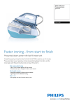
Boiler Steam Iron
GC7320
Philips Consumer Lifestyle
Service Manual
PRODUCT INFORMATION
TECHNICAL INFORMATION
Features
Iron
- Careeza soleplate
- Steam rate (Max): 110 g/min
- Steam trigger with lock
- Steam hose length: 1.8 m
Voltage
Frequency
Power Iron
Boiler
Dimension (F-box)
Weight (with packing)
Stand
- Inox boiler
- Boiler pressure: 4.5 bar
- Fixed water tank volume: 1.0 L
- Cord length: 2.0 m
- Flex & hose-cord storage hook
- Easy rinse
Water advice
If the tap water in your area is very hard, it is advisable to mix
the tap water with an equal amount of demineralised water.
09/04
220 - 240 V
50 - 60 Hz
800 W
1370 W
350 x 350 x 250 mm (L x W x H)
6.4 kg
Easy to rinse
The new design of the rinse cap makes it very easy to rinse
the boiler regularly. Simply unscrew the cap and pour out the
“dirty” water into the sink.
No hassle with coins, extra tubes or anything of this sort.
Safety Information
- This product meets the requirements regarding
interference suppression on radio and TV.
- After the product has been repaired, it should function
properly and has to meet the safety requirements as
officially laid down as this moment.
Published by Philips Consumer Lifestyle
:
:
:
:
:
:
Printed in the Netherlands
Fixed water tank
The fixed water tank that is incorporated into the stand allows
re-filling anytime during ironing. Since water is not re-filled
directly into the boiler, there is no waiting time for boiler to
cool down.
© Copyright reserved
Subject to modification
GC7320
DISASSEMBLY ADVICE - IRON
BACKPLATE 1
INLAY 4
SWIVEL 2
LAMP ASSY 7
HOSE CORD ASSY 3
MICROSWITCH ASSY 9
Remove
Disassemble
Remove
Remove
Remove
Disassemble
Remove
Disassemble
Disassemble
Screw A
BACKPLATE 1
Screw B1, B2
Clamping plate
Quick-connect S, E, L, N
SWIVEL 2
HOSE CLIP 10
Steam hose
HOSE CORD ASSY 3
TRIGGER 12
THERMOSTAT DIAL ASSY 14
HOUSING PRINTED 16
SOLEPLATE COVER 17
THERMOSTAT BUSH 19
RUBBER HOSE 20
BRASS JOINT 21
Steam hose
Power cord
S
Black
N
Blue
HOSE
CLIP 10
B2
Brown
B1
Green
Clamping
plate
Blue
E
L
N
SOLEPLATE ASSY 23
Remove
Screw A
Disassemble BACKPLATE 1
Disassemble TRIGGER 12
Tip: Disassemble TRIGGER by inserting a sharp object
into the gap at the rear of the trigger & prying
upward.
Remove
Release
Disassemble
Disassemble
Disassemble
Disassemble
Screw C
Inlay rear catch
INLAY 4
LAMP ASSY 7
MICROSWITCH ASSY 9
THERMOSTAT ASSY 14
Fig 1. Wiring at rear HOUSING (Part 1)
S
N
Black
(Microswitch)
Blue
(Micro switch)
Blue
(Lamp assy)
White
(Lamp assy)
Fig 3.
Fig 2. Wiring at rear HOUSING (Part 2)
Remove
Disassemble
Remove
Remove
Disassemble
Screws D1, D2, D3
HOUSING PRINTED 16
Screws E1, E2, E3
HOSE CLIP 22
SOLEPLATE COVER 17
2-7
PARTS LIST - IRON & ELECTRICAL DIAGRAM
GC7320
Pos
Service code
Description
1
2
3
4
5
4239 026 30740
4239 026 30750
4239 021 41080
4239 021 47570
4239 026 08280
Backplate
Swivel
Hose cord assy
Inlay Non SOS assy
Lamp cover
6
7
8
9
10
4239 026 30790
4239 021 46060
4239 026 01220
4239 021 42390
4239 010 10110
Steam lock
Lamp assy
Lamp holder
Microswitch assy
Hose clip - Iron
12
13
14
15
16
4239 026 30780
4239 014 54370
4239 021 47590
4239 026 30770
4239 021 47580
Trigger
Trigger spring
Thermostat dial assy
Rattle spring
Housing printed
17
18
19
20
21
4239 026 30760
4239 015 70150
4239 026 13220
4239 015 56530
4239 010 09350
Soleplate cover
Ryton ring
Thermostat bush
Braided rubber hose - non SOS
Brass joint
22
23
4239 010 10280
4239 021 41290
Hose clip - braided rubber hose
Soleplate assy 230 V
Thermistor 1
Trigger
Switch
L
N
L
L
N
S
Boiler Electronics
N
Thermostat
Thermal
Fuse
Pump M
Electrovalve
Boiler
Heating
Element
Thermal
Fuse
Heating
Element
STAND
IRON
Fig 4 . Electrical diagram
3-7
EXPLODED VIEW - IRON
GC7320
2
3
5
6
12
A
C
13
1
7
10
D2
B1
8
B2
9
Cord clamp
15
4
D3
21
D1
14
22
16
20
E2
17
E1
E3
19
18
22
23
4-7
DISASSEMBLY ADVICE - STAND
GC7320
TRAY RUBBER CAP 30
WATER TANK ASSY 34
TRAY ASSY 33
HOSE CORD CAP 36
DOOR ASSY 35
BOILER ASSY 38
Remove
Remove
Disassemble
Remove
Disassemble
TRAY RUBBER CAP 30 (3x)
Screw F1, F2, F3
TRAY ASSY 33
Screw G
DOOR ASSY 35
BRAIDED RUBBER HOSE BOILER 41
PUMP ASSY 45
INLET TUBE - PUMP 46
FRONT PANEL PRINTED 37
DE-AIR TUBE 47
POWER BOARD 43
RINSE RUBBER COUPLING 50
LIGHT SWITCH 44
RINSE BUSH 51
Remove
Remove
Disassemble
Remove
Disassemble
Disassemble
Disassemble
TRAY RUBBER CAP 30 (3x)
Screw F1, F2, F3
TRAY ASSY 33
Screw H1, H2
FRONT PANEL 37
LIGHT SWITCH 44
POWER BOARD 43
RINSE CAP ASSY 52
Remove
Remove
Disassemble
Remove
Disassemble
Disassemble
Disassemble
Disassemble
Disassemble
Remove
Disconnect
Disconnect
Disassemble
Disassemble
Disassemble
Remove
Disassemble
Disassemble
TRAY RUBBER CAP 30 (3x)
Screw F1, F2, F3
TRAY ASSY 33
Screw H1, H2
FRONT PANEL 37
HOSE CORD CAP 36
RINSE CAP ASSY 52
RINSE BUSH 51
RINSE RUBBER COUPLING 50
Screws K1, K2, K3, K4
INLET TUBE - PUMP 46
DE-AIR TUBE 47
WATER TANK ASSY 34
BRAIDED RUBBER HOSE - BOILER 41
PUMP ASSY 45
Torx screws L1, L2, L3
TOP SPACER 48
BOILER ASSY 38
PARTS LIST - STAND
Pos
Service code
Description
Pos
Service code
30
33
34
35
36
Description
4239 015 57990
4239 021 47640
4239 021 47600
4239 021 47680
4239 026 30800
Tray rubber cap
Tray assy
Water tank assy
Door assy
Hose cord cap
46
47
48
49
50
4239 015 56860
4239 015 56870
4239 026 26120
4239 026 26110
4239 015 56760
Inlet tube - pump
De-air tube
Top spacer
Bottom spacer
Rinse rubber coupling
37
38
39
40
41
4239 021 47620
4239 021 39540
4239 017 10420
4239 017 09890
4239 015 56880
Front panel printed
Boiler assy High End
Thermistor
Electrovalve
Braided rubber hose - boiler
51
52
55
56
57
4239 026 30820
4239 021 47630
4239 000 10100
4239 021 47610
4239 015 52340
Rinse bush
Rinse cap assy
Cordset EU
Stand bottom assy
Bung
42
44
45
4239 010 10260
4239 017 11110
4239 022 61560
Inox clamp - boiler
Light switch
Control board-Pump assy
High End
58
65
4239 026 05990
4239 026 26480
Filling cup
De-air valve High End
Note: For Pos 45, please replace both components together when either one is faulty.
The 2 components come as a service kit.
5-7
EXPLODED VIEW - STAND
GC7320
30
F3
33
F1
F2
58
G
35
K1
H1
K2
H2
41
34
36
37
52
51
50
47
40
46
45
42
65
L1
38
L2
L3
48
49
44
39
55
56
K4
Cord
clamp
Clamping
plate
K3
57
6-7
REPAIR INSTRUCTIONS
GC7320
- Due to the high wattage of the iron, only the specified cord set must be used.
- Should damage be observed on the HOSE-CORD ASSY 3 or CORDSET 55, they must be replaced.
Continued usage is not allowed.
- When replacing the MICROSWITCH ASSY 9, please dress the 2 attached wires such that they are free of tension. Pulling force
on the wires may affect the steam triggering.
- To avoid damage to the sealing & components of the BOILER ASSY 38, NEVER clean the boiler assy with vinegar, descaling
agent or other corrosive chemicals.
- When replacing ELECTROVALVE 40 or PUMP ASSY 45, please be reminded to apply loctite at the joints for good sealing.
- After the product has been repaired, it should function properly and has to meet the safety requirements & legal regulations as
laid down & officially established at this moment.
- The following tests are common checks that are conducted on a repaired product before it is returned to the consumer.
1. Soleplate temperature
Check that soleplate temperature is within IEC requirement.
Measure the temperature of the soleplate after the iron has reached steady state i.e connected to the mains for at least 15 minutes.
The table below shows the temperature requirement.
Material, for example
Minimum Maximum Nominal + Tolerance
70
120
95 ± 25
•• (2 dots)
100
160
130 ± 30
Cupro, polyester, silk, triacetate, viscose, wool
••• (3 dots)
140
210
175 ± 35
Cotton, linen
(1 dot)
Testpoint
Acetate, elastane, polyamide, polyproylene
=
•
=
Soleplate temperature (Deg C)
Marking
2. Leakage current
Check that leakage current is within IEC requirement.
Measure leakage current between LIVE/NEUTRAL & EARTH.
IEC requirement is that at 230 V supply, the EARTH leakage current must be less than 0.75 mA.
3. Water leakage / Functionality
Check that there is no water leakage from any part of the product during operation.
Check that the functionality of the product (product dependent) eg. steaming, variable steam, SOS, ASO etc is working properly.
4. Loose part
Check that there are no loose parts eg. extra screw in the product that can cause short-circuit or product malfunction.
7-7