1
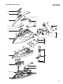
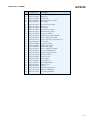
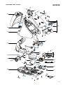
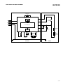
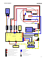
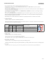
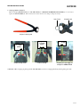
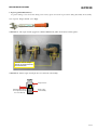
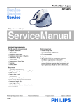
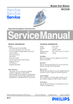
Steam Generator
GC9230
Philips Consumer Lifestyle
Service Manual
EMF & Service Information
- This product meets the requirements regarding interference
suppression on radio & TV.
- After the product has been repaired, it should function
properly & has to meet the safety requirements as officially
laid down at this moment.
PRODUCT INFORMATION
Fast & powerful crease removal
- Soleplate: SteamGlide
- OptimalTemp
- Continiuous steam output: 120 g/min
- Steam boost: 240 g/min
- Vertical steam
- Steam pressure: Up to 5.5 bar
- Steam tip
- Power: 2400 W
Easy to use
- Water tank capacity: 1500 ml
- Filling and emptying water: Detachable water tank
Extra large opening door
- Refill any time
- Heat-up time: 2 min
- Hose storage: Hose storage compartment
- Cord storage: Cord storage compartment
- Power cord lenght: 1.8 m
- Cord freedom (swivel): 180 degree cord freedom
- Hose length: 1.7 m
- Safe for all fabrics: Even for delicates like silks
- Carry Lock
11/08
1
2
Always the perfect setting thanks to:
1 - Cylonic steam chamber
2 - Advanced Smart control processor
Easy De-calc
Easy De-calc cap allows hassle free & effective scale removal
to extend the life of the steam generator.
Calc management
- Suitable for tap water
- Calc clean solution: Easy De-calc
- Calc clean reminder
Published by Philips Consumer Lifestyle
TECHNICAL INFORMATION
Voltage
: 220 - 240 V
Frequency
: 50 - 60 Hz
Power - Iron
: 800 W at 230 V
- Boiler
: 1370 W at 230 V
Dimension (F-box) : 491 mm x 305 mm x 335 mm
(Depth x Width x Height)
Weight
: Weight of iron: 1.2 kg
Weight of iron + base: 5 kg
Optimal Temp technology
- Delivers always perfect combination of steam and temperature
- 100% easy to use, no adjustment required
- 100% safe on all ironable garments
- 100% effective on all fabrics, no other iron is faster
- Tested and approved by independent textile experts
Carry Lock
Lock your iron securely & carry your appliance easy.
Printed in the Netherlands
© Copyright reserved
Subject to modification
DISASSEMBLY ADVICE - IRON
GC9230
BACKPLATE ASSY 16
SOS KNOB 13
INLAY MOLDED 17
MICRO-SWITCH ASSY 12
HOSE CORD MOUNTED
ASSY SOS 15
HOUSING & LENS
ASSY PRINTED 9
LIGHT GUIDE ASSY 10
COVER MOLDED SOS 8
DEVIATOR ASSY 3
SOLEPLATE MOUNTED
ASSY 1
Remove
Disassemble
Remove
Disassemble
Remove
Remove
Disassemble
Screw A
BACKPLATE SCREW PLATE 21
Screws B1, B2
BACKPLATE ASSY 16
Screws C1, C2
Cord clamp
SOS KNOB COVER 18
Tip for disassembling SOS KNOB COVER 18:
Carefully insert a sharp object into the gap at the side & slowly
lift up the part
Disassemble
Remove
Disassemble
Remove
Disassemble
Remove
Disassemble
Remove
Disassemble
Remove
Disassemble
Remove
Disassemble
SOS KNOB 13
Screw D
INLAY MOLDED 17
Screw E
MICRO-SWITCH ASSY 12
Screw F
HOUSING & LENS ASSY PRINTED 9
Screws G1, G2
LIGHT GUIDE ASSY 10
Screws H1 - H3
COVER MOLDED SOS 8
Screws J1 - J6
DEVIATOR ASSY 3
2-12
PARTS LIST - IRON
GC9230
Pos
Service code
Description
1
2
3
4
5
4239 021 61371
4239 021 61471
4239 021 61523
4239 015 59151
4239 010 11991
Soleplate mounted assy 230 V / 800 W
Thermistor assy Iron
Deviator assy
Braided rubber hose iron
Hose clip (ID=8.7)
6
7
8
9
10
4239 010 10281
4239 015 70153
4239 026 44621
4239 021 65551
4239 021 61771
Hose clip-Braided rubber hose
Ryton ring
Cover molded SOS
Housing & Lens assy printed
Light Guide assy
11
12
13
14
15
4239 021 64361
4239 021 61561
4239 021 65531
4239 026 42481
4239 021 63482
Deco_Plate & top Cover assy printed
Micro-switch assy
SOS knob sprayed painted
SOS lever molded
Hose cord mounted assy SOS
16
17
18
19
20
4239 021 63491
4239 026 44651
4239 026 42521
4239 026 42531
4239 014 54961
Backplate assy
Inlay molded
SOS knob cover
Trigger molded
Trigger spring
21
4239 026 42551
Backplate screw cap
3-12
GC9230
EXPLODED VIEW - IRON
18
13
D
E
Micro Switch holder
17
12
A1
11
20
21
B2
14
B1
19
C2
F
16
C1
Cord clamp
9
10
G1
H2
G2
H1
H3
15
8
J2
J1
J3
5
J4
3
J6
J5
4
6
Rubber gasket
2
7
1
4-12
DISASSEMBLY ADVICE - STAND
GC9230
WATER TANK PRINTED
ASSY 58
TRAY MOLDED 53
DISPLAY COVER PRINTED
ASSY 50
STAND TOP MOLDED 45
POWER CORD STORAGE
MOLDED 42
HOSE CORD STORAGE
COMPARTMENT ASSY 43
RINSE CAP ASSY 56
RINSE HOUSING
PRINTED 39
BOILER ASSY 36
BUTTON PANEL ASSY 51
POWER BOARD PCB
ASSY 60
Remove
Remove
Remove
Disassemble
Remove
Remove
Remove
Disassemble
Remove
Disassemble
Remove
Disassemble
Disassemble
Remove
Remove
Disassemble
Remove
Disassemble
Disassemble
Remove
Disassemble
Remove
Disassemble
WATER TANK PRINTED ASSY 58
TRAY RUBBER CAP 54
Screws K1, K2
TRAY MOLDED 53
Screws L1 - L4
Screw M
Screws N1 - N4
DISPLAY COVER PRINTED ASSY 50
Screws P1 – P3
STAND TOP MOLDED 45
Screws Q1, Q2
POWER CORD STORAGE MOLDED 42
HOSE CORD STORAGE COMPARTMENT
ASSY 43
RINSE CAP ASSY 56
Screws R1, R2
RINSE HOUSING PRINTED 39
Screws S1, S2, S3
BOILER SUPPORT BRACKET MOLDED 41
BOILER ASSY 36
Screws T1, T2
BUTTON PANEL ASSY 51
Screw U
POWER BOARD PCB ASSY 60
5-12
GC9230
PARTS LIST - STAND
Pos
Service code
Description
30
31
32
33
34
4239 021 61591
4239 021 61601
4239 026 42081
4239 015 59201
4239 010 10261
Stand bottom assy
Pump assy
De-air valve
Braided rubber hose boiler
Inox clamp
35
36
37
38
39
4239 026 32181
4239 021 61611
4239 017 10902
4239 021 61812
4239 021 65561
Spacer Bottom molded
Boiler assy
Electrovalve
Thermistor assy Boiler
Rinse Housing printed
40
41
42
43
44
4239 026 31641
4239 026 42581
4239 026 42591
4239 021 61621
4239 000 11571
Spacer top molded
Boiler support bracket molded
Power cord storage molded
Hose cord storage compartment assy
Cord set EU
45
46
47
48
49
4239 026 45051
4239 026 45061
4239 014 54982
4239 021 63721
4239 026 45091
Stand top molded
Tank Catch molded
Tank Catch Spring
Inlet coupling plate welded
De-air coupling molded
50
51
52
53
54
4239 021 65571
4239 021 61801
4239 021 64401
4239 026 42741
4239 015 59221
Display cover printed assy
Button panel assy
Front lock assy
Tray molded
Tray rubber cap
55
56
57
58
59
4239 015 59231
4239 021 61671
4239 015 58201
4239 021 63731
4239 021 61721
Rinse Rubber Bush
Rinse cap assy
O-ring
Water tank printed assy
Hall sensor PCBA assy
60
4239 021 61652
Power Board PCB assy
6-12
GC9230
EXPLODED VIEW - STAND
L1
L2
52
K1
K2
54
58
53
46
49
47
L3
L4
P2
48
50
M
P1
45
P3
42
Q2
43
37
Q1
S1
T2
S2
T1
40
36
32
51
33
U
34
31
35
60
S3
Cord
clamp
38
41
55
59
R1
R2
56
39
30
57
N4
44
N1
N3
N2
7-12
ELECTRICAL BLOCK DIAGRAM
GC9230
Thermistor
Stand Electronics
L
N
E
L
UI Board
L
Trigger
Switch
N
E
N
Power Board
Iron
LED
Hall Sensor
Board
Steam
E-valve
STAND
Boiler Heating
Element
Thermal
Fuse
Iron
Heating
Element
Thermal
Fuse
M
Pump
Thermistor
E
IRON
8-12
WIRING DIAGRAM
GC9230
#1
THERMAL
FUSE (L)
PUMP
sF
sF
#2
#1
WA19 : HE-Fuse (L)
M #1
sF
#2 M
F
#2
F
THERM-BOILER
sF
#1
THERMAL
FUSE (N)
WA20 : HE-Fuse (N)
WA3 : EARTH WIRE_BOILER
WA6 : PCB-Fuse (N)
WA5 : PCB-Fuse (L)
WA4 : PCB-EV (L)
WA7 : PCB-EV (ctrl)
WA2 : PCB-Pump (ctrl)
WA1 : PCB-Pump (L)
#2
UI
BOARD
M
#1
M
#2
M
F
EVALVE-EARTH
H
F
F
sF
V
9003 (Boiler-L)
9009 (Boiler-N)
9006 (To UI)
9014 (Live)
9007
2x
2
1
3
9012
HALL
SENSOR
BOARD
3x
2
1
3
sPB
sF
9004 (Iron Live)
NEUTRAL
9018 (Iron LED)
sM
1
TRIGGER
sF
2
THERMISTOR
9002 (Neutral)
sF
(3.96 mm)
9017
mF
9001 (Live)
POWER BOARD
sF
9015 (Evalve-Control)
9016 (Pump-Control)
9013 (Live)
7x
HOSCORD
IRON
FLEX ASSY
Sleeve - Fiber Glass
Female Push-on 5.2 x 0.8 mm L-shape Connector
Insulated Tab - Silicon Rubber
sM
Male Tab Terminal 4.8 x 0.8 mm
Ring Terminal M4.3
Female Push-on L-shape Connector 6.35 x 0.8 mm
Splice 6.0 mm
mF
Female Push-on 4.8 x 0.8 mm L-shape Connector
F
sF
LEGEND:
F
Female Push-on Connector 6.35 x 0.8 mm
M
Male Tab Terminal 6.35 x 0.8 mm
H
7-pin Board-in Connector 2 mm (horizontal)
Piggy Back Push-on Connector 4.8 x 0.8 mm
V
7-pin Connector 2 mm (vertical)
sPB
Directly soldered on PCB
9-12
GC9230
REPAIR INSTRUCTIONS
- Due to the high wattage of the iron, only the specified cord set must be used.
- Should damage be observed on the HOSE CORD MOUNTED ASSY 15 or CORD SET 44, they must be replaced.
Continued usage is not allowed.
- When replacing the MICROSWITCH ASSY 12, please dress the 2 attached wires such that they are free of tension. Pulling force
on the wires may affect the steam triggering.
- To avoid damage to the sealing & components of the BOILER ASSY 36, NEVER clean the boiler assy with vinegar, descaling
agent or other corrosive chemicals.
- When replacing ELECTROVALVE 37 or PUMP ASSY 31, please be reminded to apply loctite at the joints for good sealing.
- After the product has been repaired, it should function properly and has to meet the safety requirements & legal regulations as
laid down & officially established at this moment.
- The following tests are common checks that are conducted on a repaired product before it is returned to the consumer.
1. Soleplate temperature
Check that soleplate temperature is within IEC requirement.
Measure the temperature of the soleplate after the iron has reached steady state i.e connected to the mains for at least 15 minutes.
The table below shows the temperature requirement.
Material, for example
Minimum Maximum Nominal + Tolerance
70
120
95 ± 25
•• (2 dots)
100
160
130 ± 30
Cupro, polyester, silk, triacetate, viscose, wool
••• (3 dots)
140
210
175 ± 35
Cotton, linen
(1 dot)
Testpoint
Acetate, elastane, polyamide, polyproylene
=
•
=
Soleplate temperature (Deg C)
Marking
2. Leakage current
Check that leakage current is within IEC requirement.
Measure leakage current between LIVE/NEUTRAL & EARTH.
IEC requirement is that at 230 V supply, the EARTH leakage current must be less than 0.75 mA.
3. Water leakage / Functionality
Check that there is no water leakage from any part of the product during operation.
Check that the functionality of the product (product dependent) eg. steaming, variable steam, SOS, ASO etc is working properly.
4. Loose part
Check that there are no loose parts eg. extra screw in the product that can cause short-circuit or product malfunction.
10-12
GC9230
REPAIR INSTRUCTIONS
5. Crimping INOX CLAMP 34
When exchanging BOILER ASSY 36 or DE-AIR VALVE 32 or BRAIDED RUBBER HOSE BOILER 33, it is necessary to
replace the INOX CLAMP 34. Below instructions ensure that the inox clamp is crimped correctly.
Inox clamp
Crimping tool
Knipex Crimping tool
2.7 mm
(max)
Direct crimp form
3.5 mm
(max)
Fold in crimp
1 - 2 mm
Distance from edge of
crimp to rubber hose
CAUTION: When crimping on plastic part like DE-AIR VALVE, avoid over crimping which may lead to plastic part crack.
11-12
GC9230
REPAIR INSTRUCTIONS
6. Replacing ELECTROVALVE 37
To prevent damage to the electrovalve during service activity, please observe below precautions during disassembly & reassembly.
Tools required: Torque wrench (set to 6kgf)
CAUTION #1: The torque wrench engagement is allowed ONLY at the yellow box locations in below picture.
Contact area for torque
wrench to screw/unscrew
the electrovalve.
CAUTION #2: Ensure torque wrench jaw does not contact the solenoid body.
Torque wrench
Maintain gap between
the torque wrench and
the solenoid body
Electro-valve
solenoid body
12-12