1
HiPath 1100
HiPath 1120
HiPath 1150
HiPath 1190
Analog MF Telephones
Programming Manual
Introduction
Introduction
The HiPath 1100 family consists of the following systems: HiPath 1120, HiPath 1150 and
HiPath 1190. The features and operation of these systems are very similar. Their differences stem from their capability regarding the number of extensions, external lines and optional modules available.
The following documentation package was developed to describe the characteristics for
these systems:
• User Manual:
This manual describes step by step how to operate and use the features provided by
each system.
• Programming Manual:
The Configuration Manual briefly describes the installation of HiPath 1120, HiPath 1150,
and HiPath 1190 systems as well as the programming codes for the entire family of systems. It highlights the specific characteristics of each system.
• System Telephones Instruction Manual:
It is included with the telephone package and describes how to setup and use the telephone sets.
• Quick Reference Guide Analog and System Telephones:
This guide provides summarized information on how to use the different codes for the
features of each system.
• Attendant Console Quick Reference Guide:
This guide provides summarized information on how to use a system telephone as an
Attendant Console.
• Service Manual.
This manual contains information regarding Siemens distributors and Service Centers
where you can purchase products and obtain technical support for your Communications System.
• Warranty Certificate:
This Certificate defines the terms and conditions of the warranty provided by Siemens.
About This Programming Manual
This User Manual describes how to program the HiPath 1100 systems. It also describes all
the programming codes and functions provided by your system. Some functions may not
be available with your system. The reasons for this are the following:
• The function is not configured for your type of line and/or system. Ask your System Administrator for further information.
• Your communications platform does not support the feature. Ask about upgrade capabilities for your system.
2
Introduction
Important Notes
Do not install the system or telephone sets where there may be a risk of
explosion.
To ensure optimal performance and operation use only original accessories manufactured by Siemens.
Never open the system or dismantle any of the telephones. If you have
any problems, ask for assistance from your System Administrator.
Care of the equipment
Keep containers with liquids, such as tea, coffee, soft drinks etc. away from the system
and telephones to prevent spillage.
The information in this document provides only general descriptions of the features. The
actual features may not correspond exactly to the descriptions herein and, furthermore,
they are subject to changes to the extent that products continue to be developed.
The selection of features to be provided is not binding unless explicitly established in the
terms of the contract.
Trademarks
This equipment conforms to the EU Directive 1999/5/EG, as attested by
the CE mark.
This device has been manufactured in accordance with our certified environmental management system (ISO 14001). This process ensures the
lowest consumption of raw materials and energy as well as the lowest
production of industrial waste.
For compliance with EU directives, do not discard any batteries, electrical or electronic equipment marked with this symbol in common household garbage. Discard this type of waste at a local recycling or waste disposal facility.
3
How to use this manual
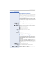
Step by step
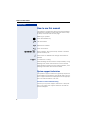
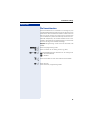
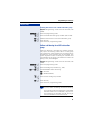
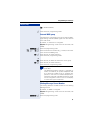
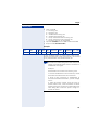
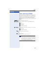
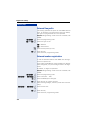
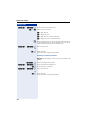
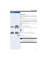
How to use this manual
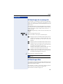
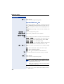
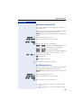
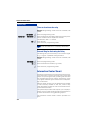
The steps for programming the system are presented
sequentially in graphic format under the column "Step
by Step" on the left side of each page.
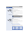
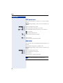
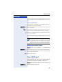
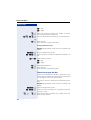
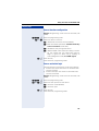
Meaning of symbols:
d
Press the Flash/Fil key.
n
Lift the handset.
t
Replace the handset.
s
Start conversation.
q, ll ,p... Enter numbers, keys, passwords, internal or external
phone numbers, etc.
w
Wait to hear an audible tone through the handset or
speaker.
<< >> An extension is calling.
When enabling certain functions and procedures, a long
beeping tone means the activation was successful).
When enabling certain functions and procedures, short
beeping tones mean the activation failed).
System support technician
The system’s support technician is generally the person
responsible for programming your HiPath 1100. The system’s support technician is equipped with the appropriate tools and information to do this.
Assistance with troubleshooting
Contact your system’s support technician. If the problem is not solved, the support technician should call
Technical Support.
4
Introduction
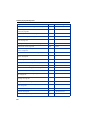
Introduction
Introduction . . . . . . . . . . . . . . . . . . . . . . . . . . . . . . . . . . 2
About This Programming Manual . . . . . . . . . . . . . . . . . . . . . . . . . . . . . . 2
Important Notes . . . . . . . . . . . . . . . . . . . . . . . . . . . . . . . . . . . . . . . . . . . 3
Trademarks . . . . . . . . . . . . . . . . . . . . . . . . . . . . . . . . . . . . . . . . . . . . . . . 3
How to use this manual . . . . . . . . . . . . . . . . . . . . . . . . 4
System support technician . . . . . . . . . . . . . . . . . . . . . . . . . . . . . . . . . . . 4
Features and options. . . . . . . . . . . . . . . . . . . . . . . . . . 13
Programming mode. . . . . . . . . . . . . . . . . . . . . . . . . . . 17
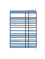
Numbering plan . . . . . . . . . . . . . . . . . . . . . . . . . . . . . . . . . . . . . . . . . . .
Flexible numbering . . . . . . . . . . . . . . . . . . . . . . . . . . . . . . . . . . . . . . . .
Activating system programming . . . . . . . . . . . . . . . . . . . . . . . . . . . . . .
Exiting programming mode . . . . . . . . . . . . . . . . . . . . . . . . . . . . . . . . . .
17
18
18
19
Important settings . . . . . . . . . . . . . . . . . . . . . . . . . . . . 20
Language . . . . . . . . . . . . . . . . . . . . . . . . . . . . . . . . . . . . . . . . . . . . . . . .
Country/group of countries . . . . . . . . . . . . . . . . . . . . . . . . . . . . . . . . . .
Dialing mode on an analog trunk . . . . . . . . . . . . . . . . . . . . . . . . . . . . . .
Default access to a group of external lines . . . . . . . . . . . . . . . . . . . . . .
Analog line attendants . . . . . . . . . . . . . . . . . . . . . . . . . . . . . . . . . . . . . .
Phonebook/Speed Dial . . . . . . . . . . . . . . . . . . . . . . . . . . . . . . . . . . . . .
Class of service (COS) . . . . . . . . . . . . . . . . . . . . . . . . . . . . . . . . . . . . . .
Denied list . . . . . . . . . . . . . . . . . . . . . . . . . . . . . . . . . . . . . . . . . . . .
Permission list . . . . . . . . . . . . . . . . . . . . . . . . . . . . . . . . . . . . . . . . .
Default permission and denied lists. . . . . . . . . . . . . . . . . . . . . . . . .
Permission for using speed dial numbers
without COS analysis. . . . . . . . . . . . . . . . . . . . . . . . . . . . . . . . . . . .
Assigning a class of service (COS). . . . . . . . . . . . . . . . . . . . . . . . . .
Special class of service for a blocked extension . . . . . . . . . . . . . . .
COS changeover . . . . . . . . . . . . . . . . . . . . . . . . . . . . . . . . . . . . . . .
Attendant console . . . . . . . . . . . . . . . . . . . . . . . . . . . . . . . . . . . . . . . . .
Carrier selection mode: LCR or ACS . . . . . . . . . . . . . . . . . . . . . . . . . . .
Warning tone for calls without LCR. . . . . . . . . . . . . . . . . . . . . . . . . . . .
Example for LCR settings on a local network . . . . . . . . . . . . . . . . . . . .
Connection of GSM/SIP boxes with LCR access . . . . . . . . . . . . . . . . .
Activating the time for LCR fallback. . . . . . . . . . . . . . . . . . . . . . . . .
Time for LCR fallback. . . . . . . . . . . . . . . . . . . . . . . . . . . . . . . . . . . .
ACS (Alternative carrier selection) . . . . . . . . . . . . . . . . . . . . . . . . . . . . .
20
20
23
23
24
26
27
27
28
29
31
32
34
36
36
37
37
38
39
39
40
40
5
Introduction
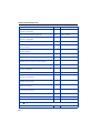
External line settings. . . . . . . . . . . . . . . . . . . . . . . . . .41
Groups of external lines. . . . . . . . . . . . . . . . . . . . . . . . . . . . . . . . . . . . . 41
Overflow for a group of external lines . . . . . . . . . . . . . . . . . . . . . . . . . . 42
Seizure priority by type of external line . . . . . . . . . . . . . . . . . . . . . . . . . 43
Analog trunk seizure protocol . . . . . . . . . . . . . . . . . . . . . . . . . . . . . . . . 43
Caller ID for analog lines . . . . . . . . . . . . . . . . . . . . . . . . . . . . . . . . . . . . 43
External line call direction . . . . . . . . . . . . . . . . . . . . . . . . . . . . . . . . . . . 45
Flash duration on analog line . . . . . . . . . . . . . . . . . . . . . . . . . . . . . . . . . 45
Reseizure timeout for an external line. . . . . . . . . . . . . . . . . . . . . . . . . . 46
Maximum time between rings for an incoming call . . . . . . . . . . . . . . . 46
Coefficient for an analog trunk . . . . . . . . . . . . . . . . . . . . . . . . . . . . . . . 47
Type of answering signal. . . . . . . . . . . . . . . . . . . . . . . . . . . . . . . . . . . . 48
Dial tone detection . . . . . . . . . . . . . . . . . . . . . . . . . . . . . . . . . . . . . . . . 49
Operation as Satellite PABX . . . . . . . . . . . . . . . . . . . . . . . . . . . . . . . . . 50
External line connection. . . . . . . . . . . . . . . . . . . . . . . . . . . . . . . . . . 50
Second external access code . . . . . . . . . . . . . . . . . . . . . . . . . . . . . 50
False tone . . . . . . . . . . . . . . . . . . . . . . . . . . . . . . . . . . . . . . . . . . . . . . . 51
Internal access code for automatic seizure . . . . . . . . . . . . . . . . . . . . . . 51
External analog present . . . . . . . . . . . . . . . . . . . . . . . . . . . . . . . . . . . . . 52
Waiting time for a second attendant to answer a call on an external analog
line . . . . . . . . . . . . . . . . . . . . . . . . . . . . . . . . . . . . . . . . . . . . . . . . . . . . . 53
Programming an extension . . . . . . . . . . . . . . . . . . . .53
Pickup groups . . . . . . . . . . . . . . . . . . . . . . . . . . . . . . . . . . . . . . . . . . . .
Alert ring timeout for Pickup groups . . . . . . . . . . . . . . . . . . . . . . . . . . .
Call groups (CG). . . . . . . . . . . . . . . . . . . . . . . . . . . . . . . . . . . . . . . . . . .
Call forwarding within a Call group (CG) . . . . . . . . . . . . . . . . . . . . .
UCD subscriber groups . . . . . . . . . . . . . . . . . . . . . . . . . . . . . . . . . . . . .
Collect call barring for a UCD subscriber group . . . . . . . . . . . . . . . .
Message waiting for UCD queue . . . . . . . . . . . . . . . . . . . . . . . . . .
UCD queue size . . . . . . . . . . . . . . . . . . . . . . . . . . . . . . . . . . . . . . . .
Time for message waiting connection to a UCD queue . . . . . . . . .
UCD overflow call destination . . . . . . . . . . . . . . . . . . . . . . . . . . . . .
Round-robin Distribution of Calls to agents . . . . . . . . . . . . . . . . . . .
Time for agent’s Notes . . . . . . . . . . . . . . . . . . . . . . . . . . . . . . . . . .
Ring Signal Timeout for agents . . . . . . . . . . . . . . . . . . . . . . . . . . . .
Agent status after signaling timeout.. . . . . . . . . . . . . . . . . . . . . . . .
Cascaded call forwarding. . . . . . . . . . . . . . . . . . . . . . . . . . . . . . . . .
Cascaded call forwarding partner . . . . . . . . . . . . . . . . . . . . . . . . . .
Time in a UCD queue. . . . . . . . . . . . . . . . . . . . . . . . . . . . . . . . . . . .
Waiting message before signaling a UCD call . . . . . . . . . . . . . . . . .
Minimum time for UCD queue on hold message . . . . . . . . . . . . . .
Hunt groups (HG) . . . . . . . . . . . . . . . . . . . . . . . . . . . . . . . . . . . . . . . . .
Search Mode for Hunt groups . . . . . . . . . . . . . . . . . . . . . . . . . . . . .
Timeout within a Hunt group . . . . . . . . . . . . . . . . . . . . . . . . . . . . . .
Call forwarding within a Hunt group (HG) . . . . . . . . . . . . . . . . . . . .
6
53
54
54
55
56
57
58
58
59
59
60
61
61
62
62
63
64
64
65
65
66
67
67
Introduction
Callback/urgent call activation for timeout . . . . . . . . . . . . . . . . . . . . . . . 68
Caller ID by name/number. . . . . . . . . . . . . . . . . . . . . . . . . . . . . . . . . . . 68
Override. . . . . . . . . . . . . . . . . . . . . . . . . . . . . . . . . . . . . . . . . . . . . . . . . 69
Silent monitoring . . . . . . . . . . . . . . . . . . . . . . . . . . . . . . . . . . . . . . . . . . 69
Caller ID for analog extension (CLIP) . . . . . . . . . . . . . . . . . . . . . . . . . . . 70
Hide group prefix . . . . . . . . . . . . . . . . . . . . . . . . . . . . . . . . . . . . . . . . . . 71
Electronic lock password. . . . . . . . . . . . . . . . . . . . . . . . . . . . . . . . . . . . 72
Timeout for call forward no answer. . . . . . . . . . . . . . . . . . . . . . . . . . . . 72
Conditional forwarding limited by extension . . . . . . . . . . . . . . . . . . . . . 73
External CFW. . . . . . . . . . . . . . . . . . . . . . . . . . . . . . . . . . . . . . . . . . 74
Call forwarding - Busy after call forwarding no answer: . . . . . . . . . . . . 74
Permission for conditional call forwarding . . . . . . . . . . . . . . . . . . . . . . . 75
Dialing mode . . . . . . . . . . . . . . . . . . . . . . . . . . . . . . . . . . . . . . . . . . . . . 75
Flash detection time . . . . . . . . . . . . . . . . . . . . . . . . . . . . . . . . . . . . . . . 76
Overflow extension . . . . . . . . . . . . . . . . . . . . . . . . . . . . . . . . . . . . . . . . 77
Hotline . . . . . . . . . . . . . . . . . . . . . . . . . . . . . . . . . . . . . . . . . . . . . . . . . . 78
Warmline . . . . . . . . . . . . . . . . . . . . . . . . . . . . . . . . . . . . . . . . . . . . . 79
Assigned group . . . . . . . . . . . . . . . . . . . . . . . . . . . . . . . . . . . . . . . . . . . 80
CD interface assignment . . . . . . . . . . . . . . . . . . . . . . . . . . . . . . . . . . . . 80
Extension coefficient . . . . . . . . . . . . . . . . . . . . . . . . . . . . . . . . . . . . . . . 81
External Message Waiting Indicator (MWI) . . . . . . . . . . . . . . . . . . . . . . 82
Activating external message waiting indicator. . . . . . . . . . . . . . . . . 82
External MWI group. . . . . . . . . . . . . . . . . . . . . . . . . . . . . . . . . . . . . 83
Waiting Message Server Number . . . . . . . . . . . . . . . . . . . . . . . . . . 83
Collect call barring by extension . . . . . . . . . . . . . . . . . . . . . . . . . . . . . . 84
Type of equipment connected to the extension . . . . . . . . . . . . . . . . . . 85
Auto-answering mode . . . . . . . . . . . . . . . . . . . . . . . . . . . . . . . . . . . . . . 85
Pulses for call charges on an analog extension . . . . . . . . . . . . . . . . . . . 86
Timer for outgoing external calls . . . . . . . . . . . . . . . . . . . . . . . . . . . . . . 87
Activate/Disable timer for outgoing external calls . . . . . . . . . . . . . . 87
Timeout for external calls . . . . . . . . . . . . . . . . . . . . . . . . . . . . . . . . . . . 87
Activate/Disable timeout for external calls. . . . . . . . . . . . . . . . . . . . 88
Defining timeout for external calls . . . . . . . . . . . . . . . . . . . . . . . . . . 89
Day to begin timeout . . . . . . . . . . . . . . . . . . . . . . . . . . . . . . . . . . . . 89
Answering timeout for a second attendant for calls received over an analog
trunk . . . . . . . . . . . . . . . . . . . . . . . . . . . . . . . . . . . . . . . . . . . . . . . . . . . 90
MSN and extension assignment for external outgoing calls . . . . . . . . . 90
Modem extension . . . . . . . . . . . . . . . . . . . . . . . . . . . . . . . . . . . . . . . . . 91
External-to-external transfer . . . . . . . . . . . . . . . . . . . . . . . . . . . . . . . . . 91
Elapsed timeout for external-to-external connection . . . . . . . . . . . . . . . 92
Configuring a timeout for an external-to-external connection . . . . . . . . 92
Disconnect timeout after and external-to-external transfer . . . . . . . . . . 93
Code to disconnect timeout after
external-to-external transfer . . . . . . . . . . . . . . . . . . . . . . . . . . . . . . . . . 93
Transfer when extension is busy. . . . . . . . . . . . . . . . . . . . . . . . . . . . . . 94
Automatic Seizure of an external line . . . . . . . . . . . . . . . . . . . . . . . . . . 94
7
Introduction
DISA . . . . . . . . . . . . . . . . . . . . . . . . . . . . . . . . . . . . . . . .95
DISA permission . . . . . . . . . . . . . . . . . . . . . . . . . . . . . . . . . . . . . . . . . . 96
MSN DISA . . . . . . . . . . . . . . . . . . . . . . . . . . . . . . . . . . . . . . . . . . . . . . . 96
DISA external line . . . . . . . . . . . . . . . . . . . . . . . . . . . . . . . . . . . . . . . . . 97
General settings . . . . . . . . . . . . . . . . . . . . . . . . . . . . . .98
Music on Hold . . . . . . . . . . . . . . . . . . . . . . . . . . . . . . . . . . . . . . . . . . . . 98
Assigning extensions to MOH groups . . . . . . . . . . . . . . . . . . . . . . . 98
Music source for the MOH group . . . . . . . . . . . . . . . . . . . . . . . . . . 99
Music source extension. . . . . . . . . . . . . . . . . . . . . . . . . . . . . . . . . . 99
External music source - extension assignment . . . . . . . . . . . . . . . 100
Setting the time for an external room monitor . . . . . . . . . . . . . . . . . . 100
Interdigit pause time setting . . . . . . . . . . . . . . . . . . . . . . . . . . . . . . . . 101
Types of caller lists . . . . . . . . . . . . . . . . . . . . . . . . . . . . . . . . . . . . . . . 102
Deleting digits from the caller list . . . . . . . . . . . . . . . . . . . . . . . . . . . . 102
Date/time - manual setting . . . . . . . . . . . . . . . . . . . . . . . . . . . . . . . . . 103
Automatic update of date/time . . . . . . . . . . . . . . . . . . . . . . . . . . . . . . 104
Callback for external calls via ISDN . . . . . . . . . . . . . . . . . . . . . . . . . . . 104
Billing . . . . . . . . . . . . . . . . . . . . . . . . . . . . . . . . . . . . . . . . . . . . . . . . . . 105
Call charge unit . . . . . . . . . . . . . . . . . . . . . . . . . . . . . . . . . . . . . . . 105
Multiplier for call charge factor . . . . . . . . . . . . . . . . . . . . . . . . . . . 105
Call charge factor for extensions . . . . . . . . . . . . . . . . . . . . . . . . . . 106
Call charge value by extension. . . . . . . . . . . . . . . . . . . . . . . . . . . . 106
Call cost limit for an extension. . . . . . . . . . . . . . . . . . . . . . . . . . . . 107
Date for updating the call cost limit for an extension . . . . . . . . . . 107
Updating the software. . . . . . . . . . . . . . . . . . . . . . . . . . . . . . . . . . . . . 108
Sw information . . . . . . . . . . . . . . . . . . . . . . . . . . . . . . . . . . . . . . . 108
Local SW update . . . . . . . . . . . . . . . . . . . . . . . . . . . . . . . . . . . . . . 108
Activating a software update . . . . . . . . . . . . . . . . . . . . . . . . . . . . . 109
Day for SW Update . . . . . . . . . . . . . . . . . . . . . . . . . . . . . . . . . . . . 109
Time for SW Update . . . . . . . . . . . . . . . . . . . . . . . . . . . . . . . . . . . 110
External number for updating the software . . . . . . . . . . . . . . . . . . 110
Frequency for SW Update . . . . . . . . . . . . . . . . . . . . . . . . . . . . . . . 110
Uploading the SW update . . . . . . . . . . . . . . . . . . . . . . . . . . . . . . . 112
Setting a System Password . . . . . . . . . . . . . . . . . . . . . . . . . . . . . . . . 112
Night service password . . . . . . . . . . . . . . . . . . . . . . . . . . . . . . . . . . . . 112
Restoring Default Settings . . . . . . . . . . . . . . . . . . . . . . . . . . . . . . . . . 113
HiPath 1120 Alarms. . . . . . . . . . . . . . . . . . . . . . . . . . . . . . . . . . . . . . . 113
Emergency numbers . . . . . . . . . . . . . . . . . . . . . . . . . . . . . . . . . . . . . . 114
Lists of emergency numbers. . . . . . . . . . . . . . . . . . . . . . . . . . . . . 115
Module Detection . . . . . . . . . . . . . . . . . . . . . . . . . . . . . . . . . . . . . . . . 115
8
Introduction
Remote administration . . . . . . . . . . . . . . . . . . . . . . . . . . . . . . . . . . . .
Service call . . . . . . . . . . . . . . . . . . . . . . . . . . . . . . . . . . . . . . . . . . .
Remote software update . . . . . . . . . . . . . . . . . . . . . . . . . . . . . . . .
Remote operation mode . . . . . . . . . . . . . . . . . . . . . . . . . . . . . . . .
Activating remote administration . . . . . . . . . . . . . . . . . . . . . . . . . .
External number configuration. . . . . . . . . . . . . . . . . . . . . . . . . . . .
remote administration password . . . . . . . . . . . . . . . . . . . . . . . . . .
Remote MSN . . . . . . . . . . . . . . . . . . . . . . . . . . . . . . . . . . . . . . . . .
Without MSN verification. . . . . . . . . . . . . . . . . . . . . . . . . . . . . . . .
Remote administration via dtmf. . . . . . . . . . . . . . . . . . . . . . . . . . .
Ending remote administration . . . . . . . . . . . . . . . . . . . . . . . . . . . .
Type of MSN signal . . . . . . . . . . . . . . . . . . . . . . . . . . . . . . . . . . . . . . .
Assigning a temporary MSN . . . . . . . . . . . . . . . . . . . . . . . . . . . . . . . .
MSN identification mode. . . . . . . . . . . . . . . . . . . . . . . . . . . . . . . . . . .
Remote administration password through an MSN . . . . . . . . . . . . . .
Delete disconnected consoles . . . . . . . . . . . . . . . . . . . . . . . . . . . . . .
PABX Trace log . . . . . . . . . . . . . . . . . . . . . . . . . . . . . . . . . . . . . . . . . .
116
116
117
117
117
118
118
118
120
120
121
121
122
122
123
123
125
Entrance telephone . . . . . . . . . . . . . . . . . . . . . . . . . . 126
Internal entrance telephone. . . . . . . . . . . . . . . . . . . . . . . . . . . . . . . . .
Configuring an internal entrance telephone . . . . . . . . . . . . . . . . . .
Door lock . . . . . . . . . . . . . . . . . . . . . . . . . . . . . . . . . . . . . . . . . . . .
DIDs for entrance telephones . . . . . . . . . . . . . . . . . . . . . . . . . . . .
Permission to open the door . . . . . . . . . . . . . . . . . . . . . . . . . . . . .
External door extension. . . . . . . . . . . . . . . . . . . . . . . . . . . . . . . . . . . .
126
126
127
127
128
129
Report. . . . . . . . . . . . . . . . . . . . . . . . . . . . . . . . . . . . . . 130
Ticket account codes. . . . . . . . . . . . . . . . . . . . . . . . . . . . . . . . . . . . . .
Account code type. . . . . . . . . . . . . . . . . . . . . . . . . . . . . . . . . . . . .
Account code confirmation . . . . . . . . . . . . . . . . . . . . . . . . . . . . . .
Data transmission rate. . . . . . . . . . . . . . . . . . . . . . . . . . . . . . . . . . . . .
25-digit suppression in CDR records . . . . . . . . . . . . . . . . . . . . . . . . . .
Call detail report for incoming calls . . . . . . . . . . . . . . . . . . . . . . . . . . .
Call detail report filter . . . . . . . . . . . . . . . . . . . . . . . . . . . . . . . . . . . . .
Call detail report through serial interface . . . . . . . . . . . . . . . . . . . . . . .
134
135
135
136
136
137
137
138
Fax/DID . . . . . . . . . . . . . . . . . . . . . . . . . . . . . . . . . . . . 139
Answering menu . . . . . . . . . . . . . . . . . . . . . . . . . . . . . . . . . . . . . . . . .
Recording a greeting . . . . . . . . . . . . . . . . . . . . . . . . . . . . . . . . . . . . . .
Call answering mode Configuration. . . . . . . . . . . . . . . . . . . . . . . . . . .
Fax reception extension . . . . . . . . . . . . . . . . . . . . . . . . . . . . . . . . . . .
Collect call barring for Fax/DID . . . . . . . . . . . . . . . . . . . . . . . . . . . . . .
MSN Answering for Fax/DID . . . . . . . . . . . . . . . . . . . . . . . . . . . . . . . .
Fax extension for MSN . . . . . . . . . . . . . . . . . . . . . . . . . . . . . . . . . . . .
Releasing Fax/DID after a timeout. . . . . . . . . . . . . . . . . . . . . . . . . . . .
140
141
143
144
145
146
146
147
9
Introduction
Digital trunk settings . . . . . . . . . . . . . . . . . . . . . . . . .148
S0 module . . . . . . . . . . . . . . . . . . . . . . . . . . . . . . . . . . . . . . . . . . . . . .
S0 ports . . . . . . . . . . . . . . . . . . . . . . . . . . . . . . . . . . . . . . . . . . . . .
Operation Mode for S0 Line . . . . . . . . . . . . . . . . . . . . . . . . . . . . .
Symmetric/Asymmetric Call . . . . . . . . . . . . . . . . . . . . . . . . . . . . .
No ACK Setup for S0 line. . . . . . . . . . . . . . . . . . . . . . . . . . . . . . . .
Notify . . . . . . . . . . . . . . . . . . . . . . . . . . . . . . . . . . . . . . . . . . . . . . .
Automatic Keypad . . . . . . . . . . . . . . . . . . . . . . . . . . . . . . . . . . . . .
Assigning a digital line to an MSN . . . . . . . . . . . . . . . . . . . . . . . . .
MSN automatic internal distribution . . . . . . . . . . . . . . . . . . . . . . .
Call deflection . . . . . . . . . . . . . . . . . . . . . . . . . . . . . . . . . . . . . . . .
ISDN Layer 1 . . . . . . . . . . . . . . . . . . . . . . . . . . . . . . . . . . . . . . . . .
ISDN Layer 2 . . . . . . . . . . . . . . . . . . . . . . . . . . . . . . . . . . . . . . . . .
B Channel . . . . . . . . . . . . . . . . . . . . . . . . . . . . . . . . . . . . . . . . . . .
"No DIV.LEG info" for ISDN line . . . . . . . . . . . . . . . . . . . . . . . . . . .
TME1 module . . . . . . . . . . . . . . . . . . . . . . . . . . . . . . . . . . . . . . . . . . .
E1 CAS access. . . . . . . . . . . . . . . . . . . . . . . . . . . . . . . . . . . . . . . .
Access S2 . . . . . . . . . . . . . . . . . . . . . . . . . . . . . . . . . . . . . . . . . . .
External line prefix . . . . . . . . . . . . . . . . . . . . . . . . . . . . . . . . . . . . . . . .
External number registration . . . . . . . . . . . . . . . . . . . . . . . . . . . . . . . .
Automatic MSN assignment via local carrier . . . . . . . . . . . . . . . . . . . .
Assignment of an MSN to attendants . . . . . . . . . . . . . . . . . . . . . . . . .
Busy signal . . . . . . . . . . . . . . . . . . . . . . . . . . . . . . . . . . . . . . . . . . . . .
Local area code filter . . . . . . . . . . . . . . . . . . . . . . . . . . . . . . . . . . . . . .
Country area code filter . . . . . . . . . . . . . . . . . . . . . . . . . . . . . . . . . . . .
148
149
150
151
151
152
152
153
154
154
155
156
156
157
158
159
159
160
160
161
161
163
164
164
ADSL expansion boards . . . . . . . . . . . . . . . . . . . . . .165
ADSL Module . . . . . . . . . . . . . . . . . . . . . . . . . . . . . . . . . . . . . . . . . . . 166
SLIMC, SADSLIM, LIMC and ADSLIM modules . . . . . . . . . . . . . . . . . 166
Default configuration of the LAN interface . . . . . . . . . . . . . . . . . . . . . 167
EVM module . . . . . . . . . . . . . . . . . . . . . . . . . . . . . . . .167
Duration of greeting messages . . . . . . . . . . . . . . . . . . . . . . . . . . . . . .
Mailbox language. . . . . . . . . . . . . . . . . . . . . . . . . . . . . . . . . . . . . . . . .
Max. number of auto-configurable mailboxes . . . . . . . . . . . . . . . . . . .
Mailbox assignments. . . . . . . . . . . . . . . . . . . . . . . . . . . . . . . . . . . . . .
Mailbox password . . . . . . . . . . . . . . . . . . . . . . . . . . . . . . . . . . . . . . . .
Enabling mailbox recording . . . . . . . . . . . . . . . . . . . . . . . . . . . . . . . . .
Type of greeting for a mailbox. . . . . . . . . . . . . . . . . . . . . . . . . . . . . . .
Mailbox greeting configuration . . . . . . . . . . . . . . . . . . . . . . . . . . . . . .
Message source . . . . . . . . . . . . . . . . . . . . . . . . . . . . . . . . . . . . . . . . .
Message mode . . . . . . . . . . . . . . . . . . . . . . . . . . . . . . . . . . . . . . . . . .
Message for MSN . . . . . . . . . . . . . . . . . . . . . . . . . . . . . . . . . . . . . . . .
System number . . . . . . . . . . . . . . . . . . . . . . . . . . . . . . . . . . . . . . . . . .
Type of system number . . . . . . . . . . . . . . . . . . . . . . . . . . . . . . . . . . .
10
168
169
170
171
171
172
172
173
173
174
174
174
175
Introduction
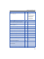
Type of voice mail . . . . . . . . . . . . . . . . . . . . . . . . . . . . . . . . . . . . . . . .
Voice mail group . . . . . . . . . . . . . . . . . . . . . . . . . . . . . . . . . . . . . . . . .
Mailbox assignment for auto-answering mode . . . . . . . . . . . . . . . . . .
Audio quality . . . . . . . . . . . . . . . . . . . . . . . . . . . . . . . . . . . . . . . . . . . .
Greeting for an analog trunk . . . . . . . . . . . . . . . . . . . . . . . . . . . . . . . .
175
176
176
176
177
Relay and sensor on the HiPath 1120 . . . . . . . . . . . 177
Sensor . . . . . . . . . . . . . . . . . . . . . . . . . . . . . . . . . . . . . . . . . . . . . . . . .
Sensor function configuration . . . . . . . . . . . . . . . . . . . . . . . . . . . .
Sensor activation logic . . . . . . . . . . . . . . . . . . . . . . . . . . . . . . . . . .
Time between attempts for activating the sensor. . . . . . . . . . . . .
MSN Assignment for the Sensor. . . . . . . . . . . . . . . . . . . . . . . . . .
Number dialed by sensor activation. . . . . . . . . . . . . . . . . . . . . . . .
Number of attempts for activating the sensor. . . . . . . . . . . . . . . .
DTMF signals for the sensor . . . . . . . . . . . . . . . . . . . . . . . . . . . . .
Sensor message . . . . . . . . . . . . . . . . . . . . . . . . . . . . . . . . . . . . . .
Relay . . . . . . . . . . . . . . . . . . . . . . . . . . . . . . . . . . . . . . . . . . . . . . . . . .
Timer to deactivate the relay . . . . . . . . . . . . . . . . . . . . . . . . . . . . .
External Ring for Activating the Relay . . . . . . . . . . . . . . . . . . . . . .
177
179
179
180
180
181
181
182
182
183
184
184
Interaction Center Smart . . . . . . . . . . . . . . . . . . . . . 184
TAC Smart - Telephony Advanced Control . . . . . . 185
HiPath 1100 Manager . . . . . . . . . . . . . . . . . . . . . . . . 186
HiPath 1100 ADSL Manager . . . . . . . . . . . . . . . . . . . 188
Siemens Admin Console . . . . . . . . . . . . . . . . . . . . . 188
Configuring the SpeedStream 4100 modem . . . . . 190
Administration of the TME1 module. . . . . . . . . . . . 190
E1 Trunk Manager . . . . . . . . . . . . . . . . . . . . . . . . . . . . . . . . . . . . . . . . 190
S2M Maintenance . . . . . . . . . . . . . . . . . . . . . . . . . . . . . . . . . . . . . . . . 191
Call Report. . . . . . . . . . . . . . . . . . . . . . . . . . . . . . . . . . 191
11
Introduction
VMIe protocol . . . . . . . . . . . . . . . . . . . . . . . . . . . . . . .192
Index. . . . . . . . . . . . . . . . . . . . . . . . . . . . . . . . . . . . . . .194
Setup and Installation . . . . . . . . . . . . . . . . . . . . . . . .198
Safety Recommendations . . . . . . . . . . . . . . . . . . . . . . . . . . . . . . . . . .
Required Tools . . . . . . . . . . . . . . . . . . . . . . . . . . . . . . . . . . . . . . . . . .
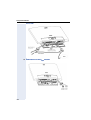
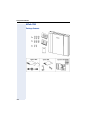
HiPath 1120 . . . . . . . . . . . . . . . . . . . . . . . . . . . . . . . . . . . . . . . . . . . . .
Package Contents . . . . . . . . . . . . . . . . . . . . . . . . . . . . . . . . . . . . .
Optional modules. . . . . . . . . . . . . . . . . . . . . . . . . . . . . . . . . . . . . .
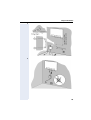
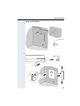
Setup and Installation. . . . . . . . . . . . . . . . . . . . . . . . . . . . . . . . . . .
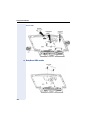
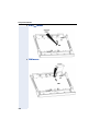
Opening the system . . . . . . . . . . . . . . . . . . . . . . . . . . . . . . . . . . .
Removing the Motherboard (MB) . . . . . . . . . . . . . . . . . . . . . . . . .
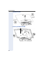
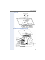
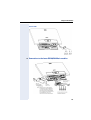
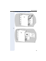
Lower modules Music, EB 200/204, LAN interface and S0 . . . . .
Master and Satellite Modules . . . . . . . . . . . . . . . . . . . . . . . . . . . .
Upper modules CTR-UP0/E, UP0/E, EVM and EB 200/204 . . . . . . .
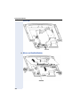
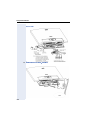
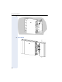
Baby Board VDC module . . . . . . . . . . . . . . . . . . . . . . . . . . . . . . . .
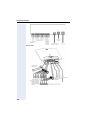
Connections to the Motherboard (MB) . . . . . . . . . . . . . . . . . . . . .
Connections to the ADSL expansion boards . . . . . . . . . . . . . . . . .
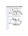
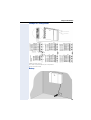
Connections to the UP0/E module . . . . . . . . . . . . . . . . . . . . . . . . .
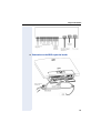
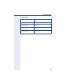
Connections to the lower EB 200/204 Music modules . . . . . . . . .
Connections to the S0 module . . . . . . . . . . . . . . . . . . . . . . . . . . .
Technical Data . . . . . . . . . . . . . . . . . . . . . . . . . . . . . . . . . . . . . . . .
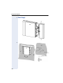
HiPath 1150 . . . . . . . . . . . . . . . . . . . . . . . . . . . . . . . . . . . . . . . . . . . . .
Package Contents . . . . . . . . . . . . . . . . . . . . . . . . . . . . . . . . . . . . .
Setup and Installation. . . . . . . . . . . . . . . . . . . . . . . . . . . . . . . . . . .
Power Supply. . . . . . . . . . . . . . . . . . . . . . . . . . . . . . . . . . . . . . . . .
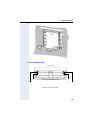
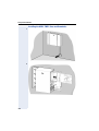
View of Module Slots . . . . . . . . . . . . . . . . . . . . . . . . . . . . . . . . . .
CTR-UP0/E Module . . . . . . . . . . . . . . . . . . . . . . . . . . . . . . . . . . . . .
EVM Module . . . . . . . . . . . . . . . . . . . . . . . . . . . . . . . . . . . . . . . . .
Installing expansion and optional modules . . . . . . . . . . . . . . . . . .
Example of a configuration . . . . . . . . . . . . . . . . . . . . . . . . . . . . . .
Battery . . . . . . . . . . . . . . . . . . . . . . . . . . . . . . . . . . . . . . . . . . . . . .
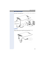
Installing the ADSL, TME1, UP0/E and S0 modules . . . . . . . . . . . .
ADSL expansion boards. . . . . . . . . . . . . . . . . . . . . . . . . . . . . . . . .
S0 module . . . . . . . . . . . . . . . . . . . . . . . . . . . . . . . . . . . . . . . . . . .
TME1 module . . . . . . . . . . . . . . . . . . . . . . . . . . . . . . . . . . . . . . . .
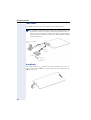
UP0/E Module . . . . . . . . . . . . . . . . . . . . . . . . . . . . . . . . . . . . . . . . .
EVM Module . . . . . . . . . . . . . . . . . . . . . . . . . . . . . . . . . . . . . . . . .
CTR-UP0/E Module . . . . . . . . . . . . . . . . . . . . . . . . . . . . . . . . . . . . .
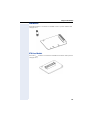
Technical Data . . . . . . . . . . . . . . . . . . . . . . . . . . . . . . . . . . . . . . . .
Internal entrance telephone. . . . . . . . . . . . . . . . . . . . . . . . . . . . . . . . .
198
199
199
199
200
201
204
204
205
206
207
208
209
211
212
213
214
215
216
216
217
218
219
220
220
221
223
223
224
225
225
226
226
227
227
228
228
Summary of programming codes . . . . . . . . . . . . . .230
12
Features and options
Features and options
The HiPath 1100 family has a basic configuration, but the systems can be reconfigured to
increase their capacities and functions through optional expansion modules, adapting it to
your business needs. The list below shows different types of access, optional modules,
and expansion modules and a table showing the capacities for each system.
• External lines:
– S0 basic access (ISDN)
– E1 CAS primary access
– Primary Access (S2
– ADSL access
– Analog line
• Internal extensions:
– System telephones:
optiPoint-type (Up0/E interface):
optiPoint 500 economy; optiPoint 500 basic, optiPoint 500 standard, optiPoint 500
advance and optipoint 500 entry
KS-type (CD interface):
Profiset 3030, E 822 ST and E 821 ST
– Analog telephones (pulse or tone)
– Answering machine
– Fax-modem
– Entrance telephone/door opener
• Interfaces:
– optiPoint analogue adapter, optiPoint ISDN adapter, optiPoint phone adapter and optiPoint acoustic adapter
– USB and V.24 adapter for system integration with applications such as CTI, HiPath
1100 Manager, billing, etc.
• Sensor and relay (Hipath1120 only)
• Expansion modules
– EB 202: 2 analog trunks and 2 analog extensions
– EB 204: 2 analog trunks and 4 analog extensions (Hipath1120 only)
– EB 206: 2 analog trunks and 6 analog extensions
– EB 210: 2 analog trunks and 10 analog extensions
– EB 200: 2 analog trunks
– EB 400: 4 analog trunks
– EB 800: 8 analog trunks
– EB 010: 10 analog extensions
– EB 012: 12 analog extensions
– UP0/e module:
Provides 2 , 4 or 8 UP0/E interfaces for connecting optiPoint-type system telephones
being. Maximum number of 8 optiPoint Masters and 8 optiPoint Slaves.
Note: The HiPath 1120 requires an additional power supply when using more than
four optiPoint 500 (Master or Slave) telephones. (See Chapter 3 (List of modules) in
the service manual - A31003-K1160-S100-*-**20))
– S0 module:
Provides access to ISDN networks through basic S0 digital access and allows for the
use of network resourcesÆ page 148.
13
Features and options
•
•
– TME1 Module
Allows you to connect a digital line with E1 CAS or S2 accessÆ page 158.
– CD 16 Module (HiPath 1190):
This module is used for connecting up to 16 KS-type system telephones.
Optional modules
– EVM Module:
Provides voice mailbox features Æ page 167.
– ADSL expansion boards: These provide a LAN Ethernet interface via their RJ45 connectors that allow you to set up a LAN, as well as providing access to and from this
network. The module used may also be equipped with an ADSL (Asymmetric Digital
Subscriber Line) modem, on which it is possible to receive high-speed data and voice
(up to 8 Mbit/s) through a single pair on a standard telephone line (POTS).
In HiPath 1100 V6.0, there is an ADSL module equipped with ADSL modem functions and a LAN interface together on the same slot Æ page 165.
In HiPath 1100 V7.0, there is a LIM module (ADSL expansion board) and the ADSL
modem can be mounted optionally on this slot.
- HiPath 1120: SLIMC module and SADSLIM module;
- HiPath 1150/1190: LIMC module and ADSLIM module;
– Music module (HiPath 1120):
Makes it possible to play music for calls on hold. The music input is provided by an
external music source, such as a radio connected to the system Æ page 98.
This module also features a relay and a sensor for supporting additional devices such
as entrance telephones, door openers, alarms, etc. Æ page 177.
– TFE entrance telephone Interface:
Makes it possible to connect an entrance telephone to an extension slot or as a pager
interfaceÆ page 126.
Optional software:
– Interaction Center Smart:
It provides management resources for Call Centers including real time information
and preconfigured reports.
– TAC Smart - Telephony Advanced Control (optional software):
With the Telephony Advanced Control Smart you can identify callers on your computer monitor, including for calls received over an analog extension. This software also
provides complete control of the telephone through a Windows interface (for making
calls, answering and transferring calls, call forwarding, and so on...).
– CallReprt is a billing system that allows you to record information about calls originated or received by your PABX system.
When a UP0/E module is connected to the HiPath 1190, the CD 16 module is
deactivated. On the HiPath 1120, the CD interfaces will be deactivated.
14
Features and options
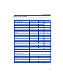
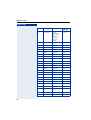
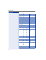
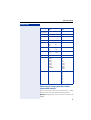
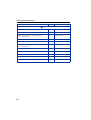
Modules and their capabilities
During system installation, please consider characteristics, recommendations and limitations of the modules that will comprise the final set (See Service manual).
Basic configuration:
HiPath 1120
Analog trunks
HiPath 1150
HiPath 1190
2
0
Analog extensions
8
10
KS system telephone interface1
4
8
8
EB 010
0
4
14
EB 012
0
3
11
EB 202
0
4
16
EB 204
2
EB 206
0
4
16
EB 210
0
4
11
EB 200
2
4
16
EB 400
0
3
10
EB 800
0
1
5
Expansion
modules2:
S0 module
0
1
TME1 module
0
UP0/E (optiPoint) module:
1
CD 16 module (KS)
2
1
2
1 or 2
0
1
Optional modules:
ADSL expansion boards
(ADSL, SLIMC, SADSLIM, LIMC
and ADSLIM modules)
1
EVM Module
1
Music module
1
TFE entrance telephone Interface
on board
20
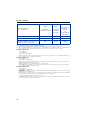
Total System Capacity:3:
Extension (analog + digital)
23
89
143
15
Features and options
System Telephones
(KS + optiPoint)
Digital line with TME1 / S0
External analog lines
Digital line (TME1) + analog line/
digital line (S0) + analog line
4 KS
or
8 optiPoint
(4 master + 4 slave)
8 KS
+
16 optiPoint
(8 master +
8 Slave)
8 KS
+
16 optiPoint
(8 master +
8 Slave)
or
24 KS (CD 16
Module)
0/2
30/10
45/20
6
16
40
0/8
32/16
45/44
[1] Each system telephone (KS) that is connected occupies one analog telephone slot.
[2] S0 and TME1 modules cannot be used simultaneously.
On the HiPath 1150 and HiPath 1190 ADSL and TME1 modules can be used simultaneously.
[3] When the maximum capacity for external lines is exceeded due to the installation of EB, S0 or TME1 modules,
the system deactivates analog trunks. Extension slots, however, continue to operate as usual.
Example 1: HiPath 1150
- Slot 0, MB 210,
- Slot 1, EB 210,
- Slot 3 TME1 - 30 digital lines
EB 210 external line will not work, but extensions will. Since the system allows for a maximum number of 32
lines we cannot have any additional analog line.
Example 2: HiPath 1150
- slot 0 MB 210
- slot 3 TME1 = 30 digital lines
In this case, there are 32 external lines at most available on the system. This means there is no room for an
additional EB module with an analog trunk.
30 CAS/S2 digital lines + 2 MB analog trunks = 32 external lines.
If an EB 200 were installed in slot 1 or slot 2 the module would not be operable, since it would exceed the system’s maximum capacity for external lines.
Example 3: HiPath 1150
- slot 0 MB 210
- slot 3 TME1 = 10 digital lines
(WARNING: Disable digital line for the TME1 Module and program unused digital lines on the switch as unavailable (turn the switch off then on).
Overall, there are 12 external lines on the system. This means there are 4 additional external lines available before reaching the maximum capacity of 16 external lines fo this combination.
An additional EB 400 could be used in Slot 1 or Slot 2.
If an EB 800 were installed on the switch, the entire module would be inoperable since it would exceed the
system’s maximum capacity for external lines.
16
Programming mode
Step by step
Programming mode
You can change the default settings of the HiPath 1100
to fit your needs. An MF-type or system telephone can
be used for this purpose, or a PC with the HiPath 1100
Manager
administration
software
installed
(Æ page 186).
The instructions that follow refer to the factory
default settings.
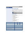
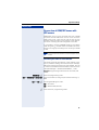
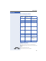
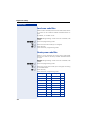
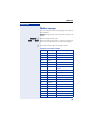
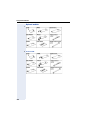
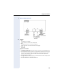
Numbering plan
The Numbering plan is configured based on the modules detected by the system.
• For the HiPath 1120:
1. Motherboard
2. S0 module
3. Analog modules/UP0/E Module
• For the HiPath 1150:
1. TME1 module;
2. Motherboard
3. S0 module
4. Analog modules/UP0/E Module
• For the HiPath 1190:
1. TME1 module;
2. Analog modules/UP0/E Module
3. S0 module
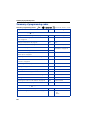
Description
HiPath 1120
HiPath 1150 HiPath 1190
External line
801 to 808
801 to 832
801 to 845
Extension, including S0
11 to 30
11 to 60
610 to 645
101 to 240
Groups of external lines
0 , 890 to 899
Call groups (CG)
770 to 779
Hunt groups (HG)
780 to 789
UCD subscriber groups
790 to 799
Carrier
9
EVM - Default internal number
790
EVM - Message ports
7491 and 7492
EVM - Virtual Ports
744 to 747
17
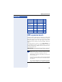
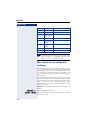
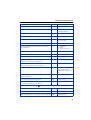
Programming mode
Step by step
Description
HiPath 1120
HiPath 1150 HiPath 1190
Fax/DID - Virtual message ports
740 to 743
USB/CAPI line
10
Substitution for * and #
75 and 76 (accordingly)
100
Flexible numbering
The pre-programmed parameters for the system numbering plan, and the features access codes as well may
have their numbers changed to fit their communication
platform using the management software HiPath 1100
Manager. For this procedure, please call the system
technical support.
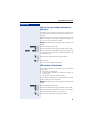
Activating system programming
n
Lift the handset at the programmer’s extension slot.
System programming can only be executed using the first slot on an analog extension of the
interface (default extension 11) equipped with an
analogextension (MF) or on a KS-type system
telephone or in the first slot of an optiPoint-type
system telephone. Programming cannot be
made on two extensions at the same time.
qmi Enter the code to activate system programming.
p Enter the system password (default is 31994 - Changing
system password Æ page 112).
w
You will hear a tone indicating that you have now accessed the programming mode.
Audible Tones in the programming mode (Brazil)
• Correct entry: 1 beep/confirmation tone.
• Incorrect entry: 3 beeps. The program will then revert back to the initial screen of the programming
mode.
• After completing the programming steps, the system responds with a confirmation tone and finalizes
the setting configuration. The program will then revert back to the initial screen of the programming
mode.
18
Programming mode
Step by step
Canceling a Setting’s Configuration
• You can cancel the configuration of a setting at any
time by pressing the "#" key. The program will then
revert back to the initial screen of the programming
mode.
Exiting a setting’s configuration
There are three different ways to finalize the configuration of a setting. After configuring the setting, you will
be returned to the initial screen of the programming
mode.
• After parameters are entered, the equipment automatically exits programming mode.
• After configuring a setting, press the # key.
• After configuring a setting, wait approximately 5
seconds.
If no code or setting is entered, the system will continue
to wait for an entry or will assume that a "null entry" occurred. It will proceed to the next programming step,
depending on the code first entered.
Exiting programming mode
After completing the configuration of a setting, you will
be returned to the initial screen of the programming
mode. Follow these steps to exit the programming
mode:
t
Replace the handset.
19
Important settings
Step by step
Important settings
Some settings may be modified right from the beginning. In most cases, however, we recommend using
the default settings. If you need to change any settings,
see the following chapters.
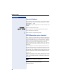
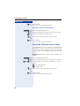
Language
Defines the language for displaying messages on the
system telephone display. This field is not automatically
updated since it is based on the country option selected. When the Language field is changed the Country is
not automatically changed. It is possible, therefore, to
select a country with a different default language. Example: Country: Brazil, Language: English.
Required: Programming mode must be activated (*95
31994).
ejh
p
w
w
Enter the programming code.
Select the language for displaying messages.
d= Custom
e=
f=
g=
h=
i=
j=
w
Portuguese
Spanish
English (default)
French
Italian
Turkish
Initial status for programming mode.
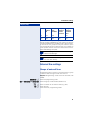
Country/group of countries
To configure the settings correctly select the country
where the system will be used.
Required: Programming mode must be activated (*95
31994).
eji
p
20
w
w
Enter the programming code.
Enter the code for the country or group of countries as
shown on the table below (e.g., "03" for Portugal).
Important settings
Step by step
w
The system restarts after the change is made.
Code Table for Countries and groups of Countries.
Code
Group
Countries
Display
Language
01
Brazil
(default)
Brazil
Bolivia
Paraguay1
Portuguese
Spanish
Spanish
02
Argentina
Argentina
Spanish
03
Portugal
Portugal
Portuguese
04
Chile
Chile
Spanish
05
Venezuela
Venezuela
Spanish
06
Mexico
Mexico
Spanish
07
Vietnam
Vietnam
English
08
IM Spanish
Columbia
Uruguay
Ecuador
Central
America
Indonesia2
Spanish
09
IM English
English
English
Saudi Arabia
Bahrain
Egypt
United Arab
Emirates
Ghana
Yemen
Iran
Jordan
Kuwait
Libya
Nigeria
Oman
Kenya
Zimbabwe
Syria
Sudan
Tanzania
Serbia/
Montenegro
21
Important settings
Step by step
22
Code
Group
Countries
Display
Language
10
IM French
Algeria
Cameroon
Ivory Coast
Lebanon
Morocco
Senegal
Tunisia
French
11
China
China
English
12
Malaysia
Malaysia
English
13
Singapore
Singapore
English
14
Thailand
Thailand
English
15
Greece
Greece
English
16
India
India
English
17
Pakistan
Pakistan
English
18
Spain
Spain
Spanish
19
Russia
Russia
English
20
Ukraine
Ukraine
English
21
Peru
Peru
Spanish
22
China 2
China 2
English
23
Philippines
Philippines
English
24
Canada
Canada
English
25
South Africa
South Africa
English
26
Turkey
Turkey
English
27
Latvia
Latvia
English
28
Lithuania
Lithuania
English
29
Italy
Italy
English
30
Australia
Australia
English
31
United
dom
King- United
dom
King- English
33
France
France
French
34
Korea
Korea
English
Important settings
Step by step
[1] For Bolivia and Paraguay, set "01=Brazil" for country/country group
then "02=Spanish" for language.
[2] For Indonesia set "08=Intern. Spanish" for country/group of countries. then "03=English" for language.
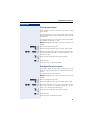
Dialing mode on an analog trunk
This features specifies the dialing mode to be used over
an analog trunk (DP or MF).
Required: Programming mode must be activated (*95
31994).
eem
p
e ... f
w
w
w
Enter the programming code.
Enter a number for an analog trunk (e.g., 801).
Enter the appropriate code:
e = Analog line: Pulse (DP)
f = Analog line: Multifrequency tone dialing (MF)
(default
for all analog lines)
p
w
Enter the next external line number.
or
r
w
Press this key.
Initial status for programming mode.
Default access to a group of external
lines
This feature configures dialing "0" for each extension as
the dialing method for a group of external lines. The default external line access code is "0."
Required: Programming mode must be activated (*95
31994).
ddf
p
p
w
w
w
p
w
Enter the programming code.
Enter the extension number (e.g. 11/101).
Enter the number for the group of external lines (e.g., 0,
890, etc).
Enter the next extension number.
or
23
Important settings
Step by step
r
w
Press this key.
Initial status for programming mode.
Example:
801 and 802 external lines are programmed as
part of the 890 group of lines.
When using code 002, Extension 11/101 is assigned to group 890. This means that when the
"0" access code is entered at this extension a
search for a free line is performed in group 890.
For code 002, when extension 11/101 is assigned
to group 0 and the external access code "0" is dialed, the search for an available line is done on
group "0."
If no available line is found and the group is programmed with code 099 "Overflow for a group of
external lines" on page 42, it will search for a line
in a different specified group.
Analog line attendants
If you want calls received over analog trunks to ring at
specified extensions at certain times of the day, all you
need to do is configure them as analog line attendants.
Any extension can also be configured as a second attendant. In this case an extension only receives a call when
the external line answering extension does not answer
the call within a specified time (Æ page 53). When this
occurs, extensions configured as second attendants for
external lines receive the call along with the first attendants.
Required: Programming mode must be activated (*95
31994).
ehf w Enter the programming code.
p w Enter a number for an analog trunk (e.g., 801).
e ... h Select the period of the day for answering calls:
e=
f=
g=
h=
24
Day
Night
Day service, second attendant
Night service, second attendant
Important settings
Step by step
p
w
...
p
w
r
w
Enter the extension numbers (e.g., 11/101) or call
groups that should signal when receiving calls from the
specified external line (up to 10 extensions or 1 group).
Press this key.
Initial status for programming mode.
To assign an extension as an attendant for different
lines, repeat the programming steps.
If an extension is connected to a door opener device, the device cannot be configured as an attendant.
Within a subscriber group an incoming call rings
at the first extension available, according to the
call distribution plan configured for the UCD subscriber group.
When no first DID is configured, the call will be
forwarded to the Overflow extension. In the
event that an Overflow extension is not configured, the call will end. In such cases no extension is signaled and the call cannot be captured.
Meanwhile, the system will continue to wait for
an available external line.
Deleting attendants for an external line
Required: Programming mode must be activated (*95
31994).
ehf w Enter the programming code.
p w Enter a number for an analog trunk (e.g., 801).
e ... h Select the period of the day for answering calls:
e=
f=
g=
h=
Day
Night
Day service, second attendant
Night service, second attendant
q w The selected line attendant will be deleted.
r w Press this key.
Initial status for programming mode.
25
Important settings
Step by step
Phonebook/Speed Dial
You can store up to 250 telephone numbers of up to 15
digits each in the System Speed Dial. You can assign a
name of up to 15 characters to each number. This allows you to do alphanumeric searches in the speed dialing phonebook (see Alphanumeric Search in the User
Manual).
To insert an interdigit pause you must enter the "P" character using the HiPath 1100 Manager or pressing the
Redial key using a system telephone (See Æ page 101).
Numbers stored in the Speed dial phonebook can be retrieved by entering their assigned speed-dial number.
This can be done from any extension that becomes free
by dialing code 072 (see Æ page 31). By default there
are no speed-dial numbers stored in the phonebook.
Required: Programming mode must be activated (*95
31994).
w
w
eef
ddd . fhm
Enter the programming code.
Enter the appropriate speed-dial number (abbreviated
number).
p Enter the internal number, Code "0" for an external line
or the external line number (e.g., 801). Then enter the
external number (up to 20 digits).
When the system is operating as a Satellite PABX, first
select a number for an external line (e.g., 801) or for a
group of external lines (e.g., 890) connected to the
PABX. Next, select the PABX internal access code or
the PABX’s Numbering plan sequence required for making an external call. Finally, enter the external number
(up to 20 digits).
Wait 5 seconds
w
Wait for a confirmation tone.
w
Initial status for programming mode.
For the HiPath 1120:
Entry 249 of the speed-dial phonebook is shared
by the relay and sensor functions and it may be
assigned a name of up to 15 characters.
A name can be assigned to the number using the
HiPath 1100 Manager.
26
Important settings
Step by step
Class of service (COS)
You can assign one of eight classes of service (COS) to
each telephone
Æ page 32). It is possible, therefore, to block outgoing
calls to certain external numbers or to allow calls to
some of those numbers only. All classes of service allow external calls to be answered and internal calls to
be made.
Classes of service
• No trunk access (no permission:
External calls only can be established using the system speed dial (once allowed by code 072), class 0.
• Outward-restricted trunk access:
You can only make external calls using the system
speed dialing phonebook or one of the permission
lists 1, 2 or 3 (Æ page 28).
• Restricted trunk access (with denied list:
You can make external calls but not to numbers on
denied lists 1, 2 or 3 (Æ page 27).
• Unrestricted trunk access (total permission):
You can make all Class 7 external calls.
Denied list
There are three lists of denied numbers that can be configured with different telephone numbers and individual
extension prefix combinations.
• Denied list 1 (COS 1) with 10 entries
• Denied list 2 (COS 2) with 25 entries
• Denied list 3 (COS 3) with 35 entries
Telephones configured for restricted trunk access (with
denied list) cannot dial numbers that start with those
combinations. If you try to dial one of these numbers,
the extension will answer with a busy signal.
Even though restrictions are set by the lists, the numbers entered in the speed dialing directory can be accessed by dialing the assigned speed-dial numbers.
The denied list may contain some combinations already
recorded, depending on the country (Æ page 29).
These can be deleted if needed.
Required: Programming mode must be activated (*95
31994).
efg
w
Enter the programming code.
27
Important settings
Step by step
e or f or g
de ... gi
w
w
Enter the denied list number you want to delete.
Enter the list entry of the number to be denied access.
p Enter the number that will be denied access (up to 16
digits).
Warning: Enter the number without the external access
code.
Wait 5 seconds
w
Wait for a confirmation tone.
Initial status for programming mode.
To change a locked number, simply enter its list
entry number and the new number.
Deleting numbers from the denied list
Required: Programming mode must be activated (*95
31994).
efg
e or f or g
de ... gi
w
w
w
Enter the programming code.
Enter the Denied List number you want to delete.
Enter the list entry number of the number to be deleted.
Wait 5 seconds If no new number is entered after 5 seconds, the content of that entry is removed.
w
Initial status for programming mode.
Permission list
There are three permission lists that can be configured
with different telephone numbers and individual extension prefix combinations (enter the number without the
external access code).
• Permission list 1 (COS 4) with 10 entries
• Permission list 2 (COS 5) with 25 entries
• Permission list 3 (COS 6) with 25 entries
In addition to speed-dial numbers, the telephones configured for outward-restricted trunk access (with permission list) can only dial numbers that start with these
combinations. When any other number is dialed, the
phone answers with a busy signal.
The permission list already contains some combinations. These can be deleted if so desired.
28
Important settings
Step by step
Required: Programming mode must be activated (*95
31994).
w
w
w
efh
h or i or j
de ... fi
Enter the programming code.
Enter the number for the permission list.
Enter the phonebook entry number for the number to
be allowed access.
p Enter the number that will be allowed access (up to 16
digits).
Warning: Enter the number without the external access
code.
Wait 5 seconds
w
Wait for a confirmation tone.
Initial status for programming mode.
To change an allowed number, just enter its list
entry number and the new number.
Deleting numbers from a permission list
Required: Programming mode must be activated (*95
31994).
efh
h or i or j
of ... fi
w
w
w
Enter the programming code.
Enter the number for the permission list.
Enter the list entry number of the number to be deleted.
Wait 5 seconds If no new number is entered after 5 seconds, the content of that entry is removed.
w
Initial status for programming mode.
Default permission and denied lists
For both permission lists and denied lists there are
some pre-programmed numbers that can be changed,
if necessary.
.
Country
Permission
list
Denied
list
Brazil
190
0800
0900
900
193
0810
Argentina
29
Important settings
Step by step
Country
Permission
list
Denied
list
Portugal
112
64
Chile
800
Venezuela
Mexico
Vietnam
IM Spanish
190
IM English
French (IM)
China
Malaysia
Singapore
999
995
1800
1608
#571#
Thailand
01
2
3
4
5
6
7
8
9
11
12
13
14
15
16
17
18
19
001
100
101
Greece
100
166
199
0800
090
Spain
091
112
1003
900
903
905
906
Russia
01
02
03
04
India
Pakistan
Ukraine
Peru
30
05
07
09
00
Important settings
Step by step
Country
Permission
list
Denied
list
Philippines
Canada
South Africa
Turkey
0900
Latvia
01
03
112
02
04
0900
Lithuania
01
03
02
112
0900
Italy
112
115
113
118
0900
Australia
000
0900
France
3010
3040
3611
0800
0810
0820
0825
083605
3
08
00
026
0269
0508
0590
0594
0596
Korea
00
01
02
03
04
05
06
07
08
Permission for using speed dial numbers
without COS analysis
Allows users with a class without permission to make
external calls using the speed dialing phonebook.
Required: Programming mode must be activated (*95
31994).
31
Important settings
Step by step
dkf
q or r
w
w
w
Enter the programming code.
To activate/deactivate the permission:
q = Activated
r = Deactivated (default)
Initial status for programming mode.
Assigning a class of service (COS)
Required: Programming mode must be activated (*95
31994).
eee
p
w
w
p
w
Enter the programming code.
Enter the number for the group of external lines (e.g., 0,
890...899).
Enter a class of service for day mode and another for
night mode:
•
•
1st digit defines the input for day service class
2nd digit defines the input for night service class
Classes of service:
d = Restricted
e = Outward-restricted trunk access with Denied
f=
g=
h=
i=
j=
k=
32
List 1
(10 slots)
Outward-restricted trunk access with Denied
List 2
(25 slots)
Outward-restricted trunk access with Denied
List 3
(35 slots)
Outward-restricted trunk access with permission list 1
(10 slots)
Outward-restricted trunk access with permission list 2
(25 slots)
Outward-restricted trunk access with permission list 3
(25 slots)
Unrestricted Trunk Access (default for all lines)
Important settings
Step by step
p
w
. p
w
Enter the extensions (e.g., 11/101) to which the COS selected will be assigned.
r
w
Press this key.
Initial status for programming mode.
To assign a COS to additional lines, repeat the programming steps described above. The default for all extensions is "77."
33
Important settings
Step by step
Special class of service for a blocked extension
This allows you to switch a blocked extension (with an
electronic lock) to any class of service.
Required: Programming mode must be activated (*95
31994).
dmj
p
p
w
w
w
r
w
Enter the programming code.
Enter the extension number (e.g. 12/102).
Enter the class of service for the extension with the activated lock:
d = No trunk access (default setting for all extensions)
e = Outward-restricted trunk access with Denied
List 1
(10 slots)
f = Outward-restricted trunk access with Denied
List 2
(25 slots)
g = Outward-restricted trunk access with Denied
List 3
(35 slots)
h = Outward-restricted trunk access with permission list 1
(10 slots)
i = Outward-restricted trunk access with permission list 2
(25 slots)
j = Outward-restricted trunk access with Permission list 3
(25 slots)
k = Unrestricted trunk access (default for all lines)
Press this key.
Initial status for programming mode.
To assign a COS to additional lines, repeat the programming steps described above.
34
Important settings
Step by step
The system administrator is responsible for
maintaining the balance of the Classes of Service used by an extension that is blocked or free.
This prevents an extension with a restricted service from having free access when the lock is not
activated and then keep an unrestricted category
when the lock is activated.
35
Important settings
Step by step
COS changeover
You can allow or deny a temporary COS changeover
from an extension to a different extension.
Required: Programming mode must be activated (*95
31994).
ekl
p
q or r
p
w
w
w
w
Enter the programming code.
Enter the extension number (e.g., 11/101).
To allow/deny COS changeover:
q = Allowed
r = Denied (default)
Enter the next extension number
or
r
w
Press this key.
Initial status for programming mode.
Attendant console
The attendant console centralizes the flow of calls at up
to two answering stations equipped with system telephones with a display. In the default configuration no attendant console is configured.
Required: Programming mode must be activated (*95
31994).
eid
p
w
w
Enter the programming code.
Enter an extension number for the attendant console
(e.g., 12/102).
p w Enter the next extension number, if you wish.
or
r
w
Press this key.
Initial status for programming mode.
Deleting an attendant console
Required: Programming mode must be activated (*95
31994).
eid
q
36
w
w
Enter the programming code.
Delete all attendant consoles.
Important settings
Step by step
r
w
Press this key.
Initial status for programming mode.
The attendant console does not receive "Direct
message to the speakerphone" and it must not
belong to any associated group.
Only the first attendant Console will be called for
digit 9. The second should be for the extension
number.
Carrier selection mode: LCR or ACS
This allows the user to change carrier selection and use
the best possible option to originate external calls.
Required: Programming mode must be activated (*95
31994).
ffi
q or r
w
w
w
Enter the programming code.
ACS/LCR:
q = ACS
r = LCR (default)
Initial status for programming mode.
When the system is configured with a carrier dialing selection mode and is reconfigured to work
with a different selection mode (for example,
ACS >>LCR), all the previous settings are lost.
Warning tone for calls without LCR
When the system is configured to use LCR, the HiPath
1100 can alert the user when an external call is being
placed to a destination using a non-default carrier with
rates that may be higher for that time of day. This may
be due to the unavailability of an external line for LCR
(Least Cost Routing).
When using a standard telephone, a warning tone indicates to the user that a different carrier is completing
the call at this time. When using a system telephone,
the carrier’s name will show on the display.
Required: Programming mode must be activated (*95
31994).
37
Important settings
Step by step
dmf
q or r
w
w
w
Enter the programming code.
Activate/Disable Tone:
q = Activated
r = Deactivated (default)
Initial status for programming mode.
This feature only works on ISDN lines.
Example for LCR settings on a local
network
This example shows the sequence for creating and distributing destinations:
"National" option
1. Create a name for the new tab, for example, National.
2. Add the carrier(s) to the existing list for long national
calls.
3. For destination, enter all area codes or partial area
codes to cover all numbers within the country.
4. Finally, enter the time intervals in the time interval
table. With time intervals left empty, the line of the
default carrier will be occupied immediately.
5. Select the line group on which calls will be made
and the overflow line group to be used when the
line group is busy.
At present, you can specify up to 100 destinations and 15 carriers
Settings must be configured using the HiPath
1100 Manager.
38
Important settings
Step by step
Connection of GSM/SIP boxes with
LCR access
GSM boxes work as if the call were sent from a GSM
cell phone and the SIP boxes work as if the call were
made using a PC. Thus the call can be sent by the
cheapest route according to the analysis of the destination of the call using the rule configured in the LCR.
It is possible to connect GSM/SIP boxes to the HiPath
1100 using the S0 module where the ISDN lines must
be set in a line group according to the carrier type: GSM
or SIP.
To install these peripherals, consult the manual
of the respective products and the support technician.
Activating the time for LCR fallback
This timer should be activated for routes subject to delays or problems making call connections (for example,
SIP boxes). When the preset time has elapsed, the call
is routed to the Default Carrier defined in that rule of the
LCR (See Manager - A31003-K1160-M810-*, LCR).
Required: Programming mode must be activated (*95
31994).
fid w Enter the programming code.
d or lmda lmm Enter the number for the group of external lines (e.g: 0,
890)
q or r
w
Activating/Disabling the timer:
w
Initial status for programming mode.
q = Activated
r = Deactivated (default)
39
Important settings
Step by step
Time for LCR fallback
This configures the routing time to the default carrier
defined in that rule of the LCR (See Manager - A31003K1160-M810-*, LCR).
Required: Programming mode must be activated (*95
31994).
fiew Enter the programming code.
di ... gd Enter the time for the exchange (from 05 to 30 seconds). Default is 05 seconds.
w
Initial status for programming mode.
ACS (Alternative carrier selection)
If the system is programmed with the ACS (Alternative
carrier selection) option, you may define in the system
which route/destination the call should follow, independently of the one selected by the user. This feature is
useful for choosing the route/destination with the
best rate when he call is actually made or for setting a
single route, once the conversion rules are duly programmed.
The first digits of the number dialed by the user are analyzed by the system. If they match the conversion rule,
they will be replaced by the default number as set forth
by that rule. The route/destination to be used can also
be predetermined. There is no field available to specify
a carrier. The carrier code must be included in the conversion rule.
Different conversion rules can be applied to the same
number, depending on the time of day and day of the
week. It is possible to define a maximum of 100 conversion rules.
When a rule uses the overflow option, it may or
may not change the dialing rule.
Example: Number dialed: 262 XXXX
Conversion Rules:
40
External line settings
Step by step
Index Number Alterna- Group of
Select- tive
external
ed
number alternative lines
Group of
external
overflow
lines
01
267
342
0
890
02
262
341
890
891
The user can use any line or group of external lines to
dial the number 262XXXX, but the system will dial the
number 341XXXX using the 890 group of external lines.
If the lines of this group are busy, the overflow option
will use the 891 group of external lines. It is possible to
insert pauses into the conversion rules (Consult the HiPath 1100 Manager help file).
You must program the conversion rules using the
HiPath 1100 Manager.
ACS does not affect emergency numbers when
the user dials directly.
External line settings
Groups of external lines
Programming allows access to an external line or group
of external lines through a code other than "0."
Required: Programming mode must be activated (*95
31994).
eij w
d or lmd to lmm
p w
r w
Enter the programming code.
Enter the group code number (default is 0).
Enter a number for an external line (e.g., 801).
Press this key.
Initial status for programming mode.
41
External line settings
Step by step
Overflow for a group of external lines
This feature makes a second group of external lines
available in the event the lines in the first group are
busy. The availability of the second group of external
lines depends on the extension’s class of service.
Required: Programming mode must be activated (*95
31994).
dmm w Enter the programming code.
d or lmd to lmm Enter the number for the group of external lines (e.g.
p
r
w
w
Select an option:
e = A specified group of external lines (the first
group is the default setting):
Enter a number to specify the overflow group to
be used:
d or lmd to lmm
f = All external line groups
g = None
Press this key.
Initial status for programming mode.
Example:
801 and 802 external lines are programmed as
part of the 890 group of lines 890.
When using code 002, Extension 11/101 is assigned to group 890. This means that when the
"0" access code is entered at this extension a
search for a free line is performed in group 890.
If no available line is found in group 890 and this
option is configured, the system will search for a
line in the overflow group.
Internet access (*493) does not work for the
overflow group.
Only one level of overflow functions.
42
External line settings
Step by step
Seizure priority by type of external line
External lines can be accessed using Code 0 or the
code for the group of lines (e.g: 890). If the switch has
analog and digital lines, you can configure the type of
line that will be given priority.
Required: Programming mode must be activated (*95
31994).
emh w Enter the programming code.
e ... g Select the type of line:
e= Independent seizure of the type of line (default).
In this case the seizure is sequential and cyclic.
f = External digital lines are activated as first option.
g = Analog trunks are activated as first option.
w
Initial status for programming mode.
Analog trunk seizure protocol
This feature specifies the protocol to be used by the
system for seizing an analog trunk, based on the local
carrier’s information.
Required: Programming mode must be activated (*95
31994).
dek w Enter the programming code.
p w Enter a number for an analog trunk (e.g., 801).
e ... f Select the type of protocol:
e = LOOP seizure (default for other countries)
f = GROUND seizure (default for Canada)
r
w
Press this key.
Initial status for programming mode.
When using the GROUND option for Canada, the
"Type of answering signal" feature for these external lines must be deactivated.
Caller ID for analog lines
43
External line settings
Step by step
HiPath 1100 systems are capable of receiving Caller ID
information through FSK and DTMF protocols over analog lines. This service must be activated by the local carrier.
The default setting depends on the country.
Required: Programming mode must be activated (*95
31994).
ddi
w
w
Enter the programming code.
Enter a number for an analog trunk (e.g., 801).
d . g Select the type of protocol:
p
w
d = deactivated
e = DTMF1
f = DTMF2 (off hook)
g= FSK
Enter the next external line number.
or
r
w
Press this key.
Initial status for programming mode.
When a Country setting is specified ("Country/
group of countries" on page 20), the appropriate
protocol is automatically selected.
Country
44
Protocol
Code
Brazil, China, India, Peru, IM-Spain DTMF1
and IM-English
1
Russia
DTMF2
(off hook)
2
Other countries
FSK
3
External line settings
Step by step
External line call direction
When a user tries to access a line, lines that have been
previously programmed as outgoing are given priority. If
an incoming call is received over that line, however, it
will come through as usual.
To avoid this situation, the method for accessing external lines can be defined at the time of making or receiving a call. This facility is usually contracted with the local
carrier to ensure optimal usage of all lines available.
Required: Programming mode must be activated (*95
31994).
eii
p
e . g
p
w
w
w
w
Enter the programming code.
Enter a number for an external line (e.g., 801).
Enter the number for the type of access to an external
line:
e = bidirectional (default)
f = incoming unidirectional
g = outgoing unidirectional
Enter the next external line number.
or
r
w
Press this key.
Initial status for programming mode.
Flash duration on analog line
The duration of the Flash signal that is sent by the system to each analog trunk can be configured individually.
Flash signal duration depends on the specific setting for
each country.
If the country configuration (Æ page 20) or the type of
analog trunk (Æ page 23) is changed, the Flash duration
will automatically reset to the default value.
Required: Programming mode must be activated (*95
31994).
eel
p
di . mm
w
w
w
Enter the programming code.
Enter a number for an analog trunk (e.g., 801).
Enter the length of time (05 to 99) for the Flash signal,
where 05 = 50 ms... 99 = 990 ms.
45
External line settings
Step by step
p
w
Enter the next number for the analog trunk.
or
r
w
Press this key.
Initial status for programming mode.
When the line is programmed directly, the default duration of the flash of the line is 240ms
and when the line is programmed with another
PABX system, the default duration of the flash is
100ms.
Reseizure timeout for an external line
There is a timeout for reseizing an external line. Once an
outgoing call has ended the line will remain blocked during the specified timeout.
Required: Programming mode must be activated (*95
31994).
efm
di ... mm
w
w
w
Enter the programming code.
Enter the length of time (05 to 99) for the Flash signal,
where 05 = 500 ms (default) to 99 = 9900 ms.
Initial status for programming mode.
Valid only for analog trunks.
Maximum time between rings for an
incoming call
This consists of the time interval between two call pulses from the local carrier (approximately 6 seconds). At
the end of this time interval, the system disconnects
from the external line and gets ready to receive other
calls.
In some countries the pause between pulses is longer
than 6 seconds. Here you can specify the setting as you
prefer.
Required: Programming mode must be activated (*95
31994).
46
External line settings
Step by step
eek
p
w
w
w
Enter the programming code.
Enter a length of time (05 to 20 seconds).
Initial status for programming mode.
Default:
• 13 seconds for Argentina,
• 04 seconds for Korea and
• 06 seconds for all other countries.
Coefficient for an analog trunk
If the appropriate impedance value or type of external
line is available, the quality of transmission and reception of information between the local carrier and the
PABX can be improved.
Required: Programming mode must be activated (*95
31994).
ehk
p
e . h
w
w
w
Enter the programming code.
Enter a number for an analog trunk (e.g., 801).
Enter the appropriate number for the type of external
line:
For example, in the case of Brazil it would be:
e = standard 900 line Ω (default)
p
r
w
f = 600 line Ω
g = short line
h = long line
Enter the next external line number.
or
w
Press this key.
Initial status for programming mode.
47
External line settings
Step by step
Type of answering signal
When a carrier provides this facility, the ticketing process occurs in real time. That is, when the called party
answers/hangs up, the public exchange sends a signal
to the system to initiate/end call detail report.
Required: Programming mode must be activated (*95
31994).
eil
p
d . f
p
w
w
w
w
Enter the programming code.
Enter a number for an analog trunk (e.g., 801).
Enter the appropriate number for signaling type:
d = None (default)
e = Polarity reversal
f = DTMF tone
Enter the next number for the analog trunk.
or
r
w
Press this key.
Initial status for programming mode.
When DTMF is selected, you must program a
tone (A, B, C or D) using Manager. If a tone is not
programmed using the Manager, the switch defaults to tone A.
When using the GROUND option for Canada,
this feature must be deactivated for external
lines.
If this feature is activated, outgoing external calls
cannot involve consultation or transfer before the
destination user picks up.
48
External line settings
Step by step
Dial tone detection
If Dial tone detection is activated on an analog line, the
number dialed will be stored and will only be sent to the
external line after the extension detects a dial tone from
the local carrier. If there is no dial tone on the line (line
not installed) the system automatically blocks this line.
With MF telephones, the number dialed will be transmitted to the external line approximately 4 to 5 seconds
after the last digit was dialed (1A dialing).
Required: Programming mode must be activated (*95
31994).
ejd
p
q or r
p
w
w
w
w
Enter the programming code.
Enter a number for an analog trunk (e.g., 801).
Activate/Disable dial tone detection for an analog trunk:
q = Activate (default)
r = Disable
Enter the number for the next external line available.
or
r
w
Press this key.
Initial status for programming mode.
49
External line settings
Step by step
Operation as Satellite PABX
When a group of external lines is configured as a
Satellite PBX, a false dial tone is not generated.
However, if LCR (code 225) or Emergency numbers (code 040) are programmed, the false dialing tone will be generated.
External line connection.
This feature determines if an analog trunk connected to
one of the HiPath 1100 systems is also connected to a
local carrier or another PABX.
Required: Programming mode must be activated (*95
31994).
egg
p w . p
w
w
e or f
w
r
w
Enter the programming code.
Enter the number for the group of external lines (e.g., 0,
890).
Enter the code for the type of connection:
e = Conneection to Local carrier (default)
f = Connection to another PABX system
Press this key.
Initial status for programming mode.
When the line is programmed as connected to a
Local Carrier, the default flash time for this line is
240 ms and when configured as a Sub-PABX, the
default time is 100 ms.
Second external access code
This setting specifies the code used by the main PABX
for accessing external lines. This code is used to check
if there is a dial tone at an external line and to generate
a pause while dialing, redialing or using the speed dialing feature.
The default setting for the second code is "0".
Required: Programming mode must be activated (*95
31994).
egh
50
w
Enter the programming code.
External line settings
Step by step
d . m or dd . mm Enter the external access code for the main PABX (one
Wait 5 seconds
w
or two digits) and wait for a confirmation tone:
d. m
= second external access code, one
digit
dd .mm = second external code, two digits
Wait for a confirmation tone.
Initial status for programming mode.
If no value is entered, a confirmation tone will
not be checked after the line is occupied.
False tone
This sends an external line dial tone even when there is
no external line available. This feature only works for MF
extensions.
Required: Programming mode must be activated (*95
31994).
djg
q or r
w
w
w
Enter the programming code.
Activate/Disable a false tone:
r = Deactivated for Argentina, Korea and India
q = Activated for all other countries (default)
Initial status for programming mode.
If LCR (configured via the HiPath 1100 Manager)
or Emergency numbers is activated, the user will
hear a false tone.
Internal access code for automatic
seizure
This features specifies the code to be used for making
internal calls when an extension is configured for automatic seizure of an external line.
Access codes are configured according to the country.
If no access code is specified, the feature will not work.
51
External line settings
Step by step
Required: Programming mode must be activated (*95
31994).
ffj
p
w
w
w
Enter the programming code.
Enter an access code consisting of a maximum of 5 digits.
Initial status for programming mode.
Default access code table by country
Country
Spain
Latvia
Lithuania
Australia
Greece
Italy
Portugal
Other
Code
99
69
6
None
External analog present
System slots that are not connected to an external line
should be configured as "unavailable".
Required: Programming mode must be activated (*95
31994).
dkm w Enter the programming code.
p w Enter a number for an external analog or digital line
(e.g., 801).
52
q or r
w
Present/Absence of an external line
r
w
Press this key.
Initial status for programming mode.
q = Presence (default)
r = Absence
Programming an extension
Step by step
In the case of an ISDN trunk, if the setting is configured as absent, two interfaces will be deactivated.
For digital lines (E1 CAS/S2) you must also program a TME1 module using the E1 Trunk Manager (E1 CAS) and S2M Maintenance (S2) applications.
Waiting time for a second attendant to
answer a call on an external analog
line
This consists of a time period (in seconds) during which
an incoming call rings at the first attendant of an external line. If the call is not answered within the specified
amount of time, it will be directed to the second attendant (Æ page 24).
The default configuration is set to 30 seconds.
Required: Programming mode must be activated (*95
31994).
qlg w Enter the programming code.
p w Enter a number for an analog trunk (e.g., 801).
de . fd Enter the activation timeout (01 to 20 in 5 second cy-
cles) where 00 = 0 seconds... 06 = 30 seconds (default), etc.
w
Initial status for programming mode.
Programming an extension
Pickup groups
Extensions can be grouped into a maximum of 16 Pickup groups. This allows an extension to answer calls that
ring at other extensions belonging to the same Pickup
group.
Required: Programming mode must be activated (*95
31994).
53
Programming an extension
Step by step
ehg
de . ej
p w . p
r
w
w
w
w
Enter the programming code.
Enter the number of the Pickup group (01 to 16).
Configure extensions for a Pickup group (e.g., 11/101).
Press this key.
Initial status for programming mode.
You can also add extensions to an existing Pickup
group.
Deleting Extensions from a Pickup group
Required: Programming mode must be activated (*95
31994).
ehg
de . ej
q
r
w
w
w
w
Enter the programming code.
Enter the number of the Pickup group (01 to 16).
Delete the extensions in the call Pickup group.
Press this key.
Initial status for programming mode.
Alert ring timeout for Pickup groups
If a call is not answered within a specified period of
time, a short alert ring is sent to the Pickup group (see
also Pickup groups).
Required: Programming mode must be activated (*95
31994).
dgi
dd . im
w
w
Enter the programming code.
Enter the length of time for the Alert Ring Signal (00 to
59 seconds).
or
q
w
Disable the alert ring signal (default).
w
Initial status for programming mode.
Call groups (CG)
Extensions can be grouped in Call groups (CG) that are
accessed by dialing a specific number ranging from 770
to 779. When the number is dialed all telephones in the
group ring until one of them is answered.
54
Programming an extension
Step by step
In the default configuration the first 10 extensions in HiPath 1100 systems belong to Call group 770.
Required: Programming mode must be activated (*95
31994).
eeg
p
p w . p
w
w
w
r
w
Enter the programming code.
Enter the Call group number (770 to 779).
Enter the extension numbers (up to 10 extensions e.g., 11/101) to be included in the subscriber group.
Press this key.
Initial status for programming mode.
Deleting extensions from a Call group (CG)
Required: Programming mode must be activated (*95
31994).
eeg
p
q
w
w
w
r
w
Enter the programming code.
Enter the Call group number (770 to 779).
All extensions belonging to the Call group selected are
deleted.
Press this key.
Initial status for programming mode.
An extension can be configured for more than
one Call group (CG).
Call forwarding within a Call group (CG)
This feature works only on digital lines. It provides call
forwarding for extensions belonging to Call groups.
When a call is routed to a Call group, it rings at all extensions at the same time. The extension configured for
call forwarding will ring at its destination. If the call is answered, the other extensions in the group stop ringing.
Otherwise, the call rings again until one of them answers it.
Required: Programming mode must be activated (*95
31994).
fff
q or r
w
w
Enter the programming code.
Activate/Disable call forwarding:
q = Activated
r = Deactivated (default)
55
Programming an extension
Step by step
w
Press this key.
Initial status for programming mode.
External call forwarding to a group member
should not be used if ""Call deflection" on
page 154" (Code 228) for that member is activated. This does not work for analog lines.
In this case, the system does not receive any information about the forwarded call having been
answered or not. Since the system does not
have this information it continues to signal all
other group members.
UCD subscriber groups
A UCD (Uniform Call Distribution) group is a group of extensions assigned to answer calls destined for a specific number that identifies the group. These internal or external calls begin to be distributed in a uniform way
between the members of the group or agents, and consider the extension that is free the longest. Calls made
to a particular extension do not affect the distribution
pattern. The calls that are not answered are not rerouted within the group.
Users can add or delete their own extensions in the
UCD group (see UCD group Login and Logout in the
User Manual).
You can also view the UCD group call statistics using
the Call Center software Interaction Center Smart.
Extensions can be grouped in a maximum of 10 UCD
groups (790 to 799). In the default configuration no extensions are assigned to subscriber groups.
Required: Programming mode must be activated (*95
31994).
56
dfg
p
p w . p
w
w
w
r
w
Enter the programming code.
Enter the UCD subscriber group number (790 to 799).
Enter the extension numbers (e.g., 11/101) to be included in the UCD subscriber group.
Press this key.
Initial status for programming mode.
Programming an extension
Step by step
Deleting Extensions from a UCD subscriber group
Required: Programming mode must be activated (*95
31994).
dfg
p
q
r
w
w
w
w
Enter the programming code.
Enter the UCD subscriber group number (790 to 799).
Deletes all extensions in the UCD subscriber group.
Press this key.
Initial status for programming mode.
Collect call barring for a UCD subscriber
group
When this blocking is activated, the system automatically rejects all incoming collect calls to a UCD group
over a digital line. Calls received over an analog line are
rejected only at the moment they are answered. The
system bypasses collect call barring for members and
non-members of the group. This means that collect call
barring is only acknowledged.
Required: Programming mode must be activated (*95
31994).
ddk
p
q or r
p
w
w
w
w
Enter the programming code.
Enter the UCD group number (e.g., 790).
Activate/Disable collect call barring.
q = Activate
r = Disable (default)
Enter the next UCD group number.
or
r
w
Press this key.
Initial status for programming mode.
If a call has been answered at least once by the
system, collect call barring cancels the blocking.
If an incoming call over a digital line is forwarded
because there was no answered (*14), and collect call barring is activated, the call will ring at
the first attendant for the external line.
57
Programming an extension
Step by step
Message waiting for UCD queue
This feature enables assigning a message or Music On
Hold for a UCD group extension when all extensions in
the group are busy.
Required: Programming mode must be activated (*95
31994).
dfh
p
p
w
w
w
Enter the programming code.
Enter the UCD group number (e.g., 790).
Enter the number for the extension connected to the
answering machine/messaging equipment (e.g., 15/
105).
or
q
w
Activates to send music from an external music source
to the UCD queue (default).
r
w
Press this key.
Initial status for programming mode.
UCD queue size
When all UCD group agents are busy or unavailable,
calls to a UCD group are placed on a waiting queue.
Calls are distributed among group members according
to priority and waiting time on the queue.
Messages or music can be played for callers that are
waiting.
This setting specifies the size of the UCD queue for
each UCD group. The default setting for UCD groups is
99 queue positions.
Required: Programming mode must be activated (*95
31994).
dfi
p
dd . mm
w
w
w
p
w
Enter the programming code.
Enter the UCD subscriber group number (e.g., 790).
Set the size of the UCD queue for a specific UCD group
(00 to 99 positions).
Enter the next UCD subscriber group number.
or
r
58
w
Press this key.
Initial status for programming mode.
Programming an extension
Step by step
Time for message waiting connection to a
UCD queue
This allows you to specify a timeout for routing calls to
a waiting queue in the event that agents are busy or unavailable.
Different timeouts can be set for each UCD group. The
default setting is for playing a message immediately or
as soon as a call is placed in a queue.
Required: Programming mode must be activated (*95
31994).
dfj
p
dd . mm
w
w
w
p
w
Enter the programming code.
Enter the UCD subscriber group number (790 to 799).
Enter a timeout for enabling message playing (00 to 99
in 5-second cycles) where 00 = 0 seconds (default)... 06
= 30 seconds, etc.
Enter the next UCD subscriber group number.
or
r
w
Press this key.
Initial status for programming mode.
UCD overflow call destination
This setting specifies a call destination for each UCD
group when:
• All agents are logged out
• A UCD queue reaches the maximum number of
calls waiting
• The queue’s overflow timeout expires.
In the default configuration the destinations for UCD
groups overflow are not specified.
Required: Programming mode must be activated (*95
31994).
dfk
p
p
w
w
w
p
w
Enter the programming code.
Enter the UCD subscriber group number (790 to 799).
Enter the overflow call destination. This can be a different UCD subscriber group or an extension.
Enter the next UCD subscriber group number.
or
59
Programming an extension
Step by step
r
w
Press this key.
Initial status for programming mode.
Deleting an overflow call destination
dfk
p
q
p
w
w
w
w
Enter the programming code.
Enter the UCD subscriber group number (790 to 799).
Deletes the overflow call destination.
Enter the next UCD subscriber group number.
or
r
w
Press this key.
Initial status for programming mode.
Round-robin Distribution of Calls to agents
This setting allows you to configure a round-robin type
distribution of calls so each call rings automatically at
the station of the next available agent. If no agents are
logged in, calls are forwarded to an overflow call destination.
Required: Programming mode must be activated (*95
31994).
dfl
p
q or r
p
w
w
w
w
Enter the programming code.
Enter the UCD subscriber group number (790 to 799).
Activate/Disable round-robin distribution of calls to
agents:
q = Activated (default)
r = Deactivated
Enter the next UCD subscriber group number.
or
r
60
w
Press this key.
Initial status for programming mode.
Programming an extension
Step by step
Time for agent’s Notes
Upon ending a UCD call an agent may need to make
some notes.
This features allows you to set a period of time for the
agent to leave the group and make notes about the call
undisturbed.
The default setting is for the agent to become available
immediately at the end of a call.
Required: Programming mode must be activated (*95
31994).
dfm
p
dd . mm
w
w
w
p
w
Enter the programming code.
Enter the UCD subscriber group number (790 to 799).
Specify the time for the agent to take notes (00 to 99 in
5-second cycles) where 00 = 0 seconds (default)... 06 =
30 seconds, etc.
Enter the next UCD subscriber group number.
or
r
w
Press this key.
Initial status for programming mode.
Ring Signal Timeout for agents
This setting specifies how long an incoming call will
keep on ringing at each agent’s station before overflow
occurs.
The default setting is 30 seconds.
Required: Programming mode must be activated (*95
31994).
dgd
p
de . mm
w
w
w
p
w
Enter the programming code.
Enter the UCD subscriber group number (790 to 799).
Enter the timeout for a call to ring at an agent’s station
(01 to 99 in cycles of 5 seconds) where 01 = 5 seconds... 06 = 30 seconds (default), etc.
Enter the next UCD subscriber group number.
or
r
w
Press this key.
Initial status for programming mode.
61
Programming an extension
Step by step
Agent status after signaling timeout.
Allows you to identify agent’s status at the end of the
signaling timeout.
By default, once the signaling timeout expires the call is
transferred to a different group member and the agent
becomes unavailable (see User Manual - available/unavailable agent for a UCD group).
Required: Programming mode must be activated (*95
31994).
ekj
p
q or r
p
w
w
w
w
Enter the programming code.
Enter the UCD subscriber group number (790 to 799).
Select a status to be displayed for the agent after signaling timeout expires:
q = Available
r = Unavailable (default)
Enter the next UCD subscriber group number.
or
r
w
Press this key.
Initial status for programming mode.
Cascaded call forwarding
This allows a call to be forwarded up to the third destination, regardless of the type of call forwarding, i.e.,
destination 1 has call forwarding to destination 2 and
destination 2 has call forwarding to destination 3. Any
call to destination 1 will be forwarded to destination 3.
If destination 3 has call forwarding, the operation will
not be performed.
The destination can be configured with call forward no
answer and/or with unconditional call forwarding.
Independently of the level of call forwarding, if the extension called has call forward no answer, this will be
called if there is no answer from the destination of the
unconditional call forwarding. If the extension called
does not have call forward no answer, the next call forward no answer in the cascade will be called.
Example:
62
Programming an extension
Step by step
•
Number 1 configured with unconditional call forwarding to number 2 and with call forward no answer to number 4, and number 2 configured with
unconditional call forwarding to number 3 and with
call forward no answer to number 5: a call to number
1 will be forwarded to number 3, and if number 3
does not answer, the call will be forwarded to number 4. Call forward no answer of number 2 will be ignored.
Cascaded call forwarding partner
Cascaded call forwarding allows you to choose how the
call forwarding partner will be displayed on the telephone display.
In the following situation: Number 1 is set to forward to
number 2 and number 2 is set to forward to number 3.
Here, the display can be configured as follows:
•
Last partner: the caller display will show the following: "forwarded to: number 3” and number 3 display
will indicate: "from: number 1.
•
First partner: the caller display will show the following: "forwarded to: number 2” and number 3 display
will indicate: "from: number 2".
If number 3 is a VMI:
• Last: The message is stored in number 1’s
mailbox. If number 1 does not have a mailbox, the voice mail must request the port for
recording the message
• First: The message is stored in number 2’s
Mailbox.
Required: Programming mode must be activated (*95
31994).
ele
d or e
w
w
w
Enter the programming code.
Enter the code for the display mode:
d = Last (default)
e = First
Initial status for programming mode.
63
Programming an extension
Step by step
Time in a UCD queue
This setting specifies the maximum length of time a call
is allowed to remain in a UCD queue.
Once the time expires, the call is disconnected or forwarded to a UCD overflow call extension. The default
setting for a call to remain in a queue is 1 minute.
Required: Programming mode must be activated (*95
31994).
dge
p
dd . mm
w
w
w
p
w
Enter the programming code.
Enter the UCD subscriber group number (790 to 799).
Enter the time allowed for a call to remain in a queue (00
to 99 in cycles of 5 seconds) where 00 = 0 seconds...
06 = 30 seconds... 12 = 1 minute (default), 99 = 8 minutes, 15 seconds.
Enter the next UCD subscriber group number.
or
r
w
Press this key.
Initial status for programming mode.
Waiting message before signaling a UCD call
This feature allows you to connect a call waiting message for incoming calls before they ring at a UCD extension.
Required: Programming mode must be activated (*95
31994).
dgf
p
q or r
w
w
w
p
w
Enter the programming code.
Enter the UCD subscriber group number (790 to 799).
Activate/Disable call waiting message:
q = Activated
r = Deactivated (default)
Enter the next UCD subscriber group number.
or
r
64
w
Press this key.
Initial status for programming mode.
Programming an extension
Step by step
Minimum time for UCD queue on hold message
This setting specifies a minimum length of time until a
message is played for calls waiting in a UCD queue.
Required: Programming mode must be activated (*95
31994).
dgg
p
dd . mm
w
w
w
p
w
Enter the programming code.
Enter the UCD subscriber group number (790 to 799).
Enter the minimum amount of time (00 to 99 in cycles
of 5 seconds) where 00 = 0 seconds (default)... 01 = 5
seconds (default)... 06 = 30 seconds, etc.
Enter the next UCD subscriber group number.
or
r
w
Press this key.
Initial status for programming mode.
This feature only works when the Time in a UCD
queue option (Code 031) is activated.
Hunt groups (HG)
A Hunt group is a group of extensions for answering
calls directed to a specific number identifying the
group. When an extension does not answer an internal
or external call within a specified period of time (see
Timeout within a Hunt group), the call will ring consecutively at the extensions that are available within the
group. When there is no signal, the extension may disconnect from the Hunt group.
Extensions can be grouped in a maximum of 10 Hunt
groups (780 to 789). The default setting assigns no extensions to Hunt groups.
Required: Programming mode must be activated (*95
31994).
dfe
p
p
w
w
w
Enter the programming code.
Enter the Hunt group number (780 to 789).
Enter the extension numbers (e.g., 11/101) to be included in the Hunt group.
65
Programming an extension
Step by step
r
w
Press this key.
Initial status for programming mode.
Deleting extensions from Hunt groups
Required: Programming mode must be activated (*95
31994).
dfe
p
q
r
w
w
w
w
Enter the programming code.
Enter the Hunt group number (780 to 789)
Delete all extensions in the Hunt group.
Press this key.
Initial status for programming mode.
This feature only works for digital lines.
Search Mode for Hunt groups
This setting specifies how each Hunt group will conduct
a search for an available extension: linear search or
round-robin search.
• A linear search always starts from the first extension
in the group
• A round-robin search starts after the last extension
selected
Required: Programming mode must be activated (*95
31994).
dff
p
e or f
w
w
w
p
w
Enter the programming code.
Enter the Hunt group number (780 to 789).
Select the search mode:
e = Linear (default)
f = Cyclical
Enter the next Hunt group number.
or
r
66
w
Press this key.
Initial status for programming mode.
Programming an extension
Step by step
Timeout within a Hunt group
This sets a time interval in which the external or internal
call must be answered by the member of the group. Different times may be set for each group. If the call forwarding times out before the member of the group answers, the call will ring consecutively in the other free
extensions of the group.
Required: Programming mode must be activated (*95
31994).
fhf w Enter the programming code.
p w Enter the Hunt group number (780 to 789).
de . fh Enter the length of time (01 to 24 in cycles of 5 seconds)
where 01 = 5 seconds... 04 = 20 seconds (default).
w
Initial status for programming mode.
The Hunt group will not be forwarded or overflow if the call is not answered.
Call forwarding within a Hunt group (HG)
This feature only works for digital lines. It provides call
forwarding for extensions belonging to Hunt groups.
When a call is directed to a group, it rings at each extension, according to the group settings (linear or roundrobin) When an extension is set for call forwarding, calls
are routed to the destination as configured. If a call is
not answered, the other extensions in that group do not
ring. When no call forwarding is set, calls ring at the other extensions, as configured for the Hunt group.
Required: Programming mode must be activated (*95
31994).
ffg
q or r
w
w
w
Enter the programming code.
Activate/Disable call forwarding:
q = Activated
r = Deactivated (default)
Initial status for programming mode.
67
Programming an extension
Step by step
When the ""Call deflection" on page 154" feature
(Code 228) is activated, there should not be external call forwarding to an extension that is a
member of a group. (does not work on analog
lines)
In this case, the system does not receive any information about the forwarded call having been
answered or not. Since the system does not
have this information it continues to signal all
other group members.
Callback/urgent call activation for timeout
When an extension or external number is busy, this configuration allows you to set a timeout for enabling the
Callback or Urgent Call features after approximately 7
seconds when the extension or external number called
(via digital ISDN line) is busy..
Required: Programming mode must be activated (*95
31994).
dgk
q or r
w
w
Enter the programming code.
Activate/Disable the features:
q = To activate Callback and deactivate Urgent Call
r = To deactivate Callback and activate Urgent Call
(default)
w
Initial status for programming mode.
Caller ID by name/number
This feature enables Caller ID information to be displayed on an extension’s telephone display.
Required: Programming mode must be activated (*95
31994).
dgm
e . g
68
w
w
Enter the programming code.
Select the information to be shown on the display:
e = Name and number (default)
f = Name only
Programming an extension
Step by step
g = Number only
w
Initial status for programming mode.
Override
This settings allows an extension to override another
extension when there is a conversation in progress.
When this is done, the call that is overridden receives a
warning tone.
Required: Programming mode must be activated (*95
31994).
ehh
p
d or e
w
w
w
Enter the programming code.
Enter the extension number (e.g. 12/102).
Enter a permission type:
d = no permission to override (default)
e = with permission to override and sending warning
tone
p
w
Enter the next extension number.
or
r
w
Press this key.
Initial status for programming mode.
Within the system, an override has the same limitations as a conference or silent monitoring, that
is, a maximum of 2 simultaneous overrides are
allowed. Important: The Silent monitoring feature is ticketed as an Override.
Silent monitoring
This feature allows an extension to override another extension without sending a warning signal to the parties
having a conversation (for certain countries only).
Required: Programming mode must be activated (*95
31994).
dhj
p
w
w
Enter the programming code.
Enter the extension number (e.g. 11/101).
69
Programming an extension
Step by step
q or r
p
w
w
Activate/Disable permission for Silent monitoring of a
specific extension:
q = Activated
r = Deactivated (default)
Enter the next extension number.
or
r
w
Press this key.
Initial status for programming mode.
On Profiset 3030 telephones, the MUTE option
is automatically activated with Silent monitoring.
Within the system, Silent monitoring has the
same limitation as the Conference and Override
features.
A maximum of 2 simultaneous conferences is allowed by the system. Important: Override iis
ticketed as a conference.
If the monitoring or the monitored party change
status, silent monitoring will be canceled. This occurs, for example, when a call is placed on hold.
Caller ID for analog extension (CLIP)
When the system receives an incoming call with caller
ID (activated by the local carrier), the extension configured to use this feature receives and displays the caller’s data on the telephone display.
For example,
• E805C (Brazil)
• Profiset 3020
• Profiset 3025
• Gigaset 4010
The telephone must have an external power supply and
comply with the appropriate regulations.
Required: Programming mode must be activated (*95
31994).
ded
p
p
70
w
w
w
Enter the programming code.
Enter the analog extension number (e.g., 12/102).
Select the type of configuration:
d = no Caller ID (default)
Programming an extension
Step by step
e = DTMF prior to ringing
f = DTMF during ringing
g = FSK before ringing (Default for Korea)
h = FSK during ringing
i = FSK prior to ringing or during a conversation
(default for France)
p
w
j = FSK during ringing or a conversation
Enter the next analog extension number.
or
r
w
Press this key.
Initial status for programming mode.
If the country set (code 165 Æ page 20) is France,
the CLIP FSK feature will be available for the HiPath 1120 only.
Hide group prefix
This settings allows an extension to receive an external
call over an external line belonging to a group of external
lines, and to hide the group number so it does not show
on the display. When a special access call is received
and transferred to an extension with this feature is activated, the external line number does not show on the
display.
Example: An analog extension receives an external call
over an external line that belongs to group 890 - number
24987049. When this feature is activated, the display
show only 24987049. When this feature is deactivated,
the display shows 89024987049, that is, the number for
the group of external lines followed by the external
number.
Required: Programming mode must be activated (*95
31994).
ell
p
q or r
w
w
w
Enter the programming code.
Enter the analog extension number (e.g., 12/102).
To activate/deactivate external CFW:
q = Activated
r = Deactivated (default)
71
Programming an extension
Step by step
p
w
Enter the next analog extension number
or
r
w
Press this key.
Initial status for programming mode.
To enable this feature, analog extensions must
be configured for CLIP.
Electronic lock password
This option allows you to set a 5-digit password to protect an extension against unauthorized use. When this
option is selected, only internal calls or Speed Dial calls
can be made from the extension. If the user of an extension forgets the password used to block the extension, the password can be reset to the system’s default
(default password is 0000).
Required: Programming mode must be activated (*95
31994).
efj
p
p
w
w
w
Enter the programming code.
Enter the extension number (e.g. 12/102).
Enter a 5-digit password to set an electronic lock for the
extension (default is 00000)
or
q Delete the electronic lock password (it defaults to
00000)
w
Initial status for programming mode.
A blocked extension can only make internal calls
using the system speed dialing phonebook (abbreviated numbers) if its class of service is not
changed (see Special class of service for a
blocked extension).
Timeout for call forward no answer
This feature specifies a timeout for the first attendant to
answer an incoming call. If the call is not answered, it is
forwarded to a second attendant, as programmed (see
call forward no answer in the User Manual).
72
Programming an extension
Step by step
Required: Programming mode must be activated (*95
31994).
egd w Enter the programming code.
de . mm Enter the length of time (01 to 99 in cycles of 5 seconds)
where 01 = 5 seconds... 06 = 30 seconds (default).
w
Initial status for programming mode.
Conditional forwarding limited by extension
l
This configuration is available through a CTI interface
Incoming calls can be forwarded to a specified destination list, as configured in a TAPI-type application such as
a Windows TAPI Browser. The settings of the previous
list or unconditional call forwarding will be replaced with
the new list settings.
The following information is required for configuring a
list:
• Incoming caller ID
• Day of the week and time
• Type of call (internal or external)
When more than one number have been specified for
incoming calls to an extension, the call forwarding priority will be:
1. Checks to see if the Caller ID for the incoming call
matches the number programmed for the extension
2. Checks to ensure that the Type of Call (internal or external) has been configured
3. Checks the time settings.
Required: Programming mode must be activated (*95
31994). The extension has permission for a conditional
call forwarding.
dmk w Enter the programming code.
de . id Enter the number of digits that can be programmed for
extensions with permission (default is 5).
w
Initial status for programming mode.
73
Programming an extension
Step by step
Conditional call forwarding has priority over an
unconditional call forwarding.
Conditional call forwarding is not available for S0
extensions.
function: The extension has external CFW and
the system is connected to a PC running a TAPI
application.
1. Conditional call forwarding rules and conditions for a specified extension can be defined
by using a Windows TAPI application
2. Apply the settings to the extension desired.
3. From this moment on the extension will be
forwarded.
External CFW
Required: Programming mode must be activated (*95
31994).
dml
p
q or r
w
w
w
w
Enter the programming code.
Enter the extension number (e.g. 12/102).
To enable/deactivate External CFW:
q = Activated
r = Deactivated (default)
Initial status for programming mode.
Call forwarding - Busy after call forwarding no answer:
This option allows an incoming call to an extension configured for call forward no answer (see User Manual.
Call forwarding - no answer ) can be forwarded to the
same destination configured if the extension is busy
when the call is made.
Required: Programming mode must be activated (*95
31994) and call forward no answer must be activated as
well.
eli w Enter the programming code.
p w Enter the extension number (e.g., 12/102).
74
Programming an extension
Step by step
q or r
p
w
w
To enable or deactivate permission for call forwarding Busy:
q = Activated
r = Deactivated (default)
Enter the next extension number
or
w
r
Press this key.
Initial status for programming mode.
Urgent call and callback when busy facilities do
not work when call forwarding - busy and call forward no answer are activated.
If the extension called is configured to use Do
not disturb and call forwarding - Busy then the
call will be forwarded. If Do not disturb is activated at the destination to which the call is forwarded, the caller will hear a busy signal.
Permission for conditional call forwarding
This allows an extension to forward a call to an external
line.
Required: Programming mode must be activated (*95
31994).
fhk
p
q or r
p
w
w
w
w
Enter the programming code.
Enter the extension number (e.g., 12/102).
To enable/deactivate permission for external line call forwarding:
q = Activated (default)
r = Deactivated
Enter the next extension number
or
r
w
Press this key.
Initial status for programming mode.
Dialing mode
75
Programming an extension
Step by step
The Dialing mode designates the dialing method as
pulse (DP), tone (DTMF) or automatic detection.
Required: Programming mode must be activated (*95
31994).
ejl
p
d . f
p
w
w
w
w
Enter the programming code.
Enter the extension number (e.g., 12/102).
Enter the code for the dialing mode:
d = Automatic identification (default)
e = Pulse (DP)
f = Multifrequency (MF)
Enter the next extension number
or
r
w
Press this key.
Initial status for programming mode.
Flash detection time
The Flash detection time is the maximum period of
time required by a PABX to detect a flash signal generated by an internal telephone. If older MF dialing telephones are connected to the system, it may be necessary to adjust the Flash detection time to their response
times (see manufacturer’s instructions). The specified
Flash detection time may vary for different countries.
Required: Programming mode must be activated (*95
31994).
ege w Enter the programming code.
p w Enter the extension number (e.g. 12/102).
dde . fid Enter the Flash detection time (001 to 250, in cycles of
10 ms). 001 = 10ms ... 010 = 100 ms ... 035 = 350 ms,
etc.
Default:
• 035 - Portugal, Argentina and Thailand
• 036 - for Korea
• 028 - for all other countries.
p
w
or
76
Enter the next extension number.
Programming an extension
Step by step
r
w
Press this key.
Initial status for programming mode.
The system allows automatic detection of the
flash time using the "Flash detection time on the
extension - *9495" feature - see User Manual.
Overflow extension
An overflow extension receives calls when the extension called is not available.
Examples:
• The extension called is activated for room monitoring (Babyphone)
• The extension that was programmed as the first attendant is currently assigned as internal entrance
telephone
• No extension is configured (all extensions were deleted using the code "42").
By default, the first extension of the system is configured as the overflow extension for Busy signal or Wrong
Number.
Required: Programming mode must be activated (*95
31994).
egf
e . g
w
w
Enter the programming code.
Choose a list for call forwarding:
e = No answer
f = Busy
g = Wrong number
p Enter the extension number (e.g. 12 /102) to be added
to the list.
w
Initial status for programming mode.
The overflow extension is accessed using your
own internal number.
The overflow extension cannot be configured or
used for Fax.
77
Programming an extension
Step by step
Hotline
With this feature a number entered in the speed dialing
phonebook can be called automatically as soon as the
handset is lifted without having to dial it manually.
An administrative extension (11/101), an overflow extension or a door opener extension cannot be configured
as a Hotline. If a Hotline is assigned to a certain extension and one of these features is activated, the Hotline
will be automatically removed from that extension.
By default, no telephone is configured as a Hotline.
Required: Programming mode must be activated (*95
31994).
Activation of Hotline mode
ehi
p
w
w
p
w
Enter the speed dialing number you want to select
(e.g., 000 to 249).
p
w
Enter the next extension number.
Enter the programming code.
Enter the extension number (e.g. 12/102) to be assigned a Hotline mode.
or
r
w
Press this key.
Initial status for programming mode.
Any entry in the speed dialing phonebook can be
configured as a Hotline for many extensions.
There is an option that allows you to time the call
for a specified speed dialing number: the Warmline (code 162). The extension can dial any number until the system times out.
Disabling Hotline mode
Required: Programming mode must be activated (*95
31994).
78
ehi
p
w
w
q
p
w
w
Enter the programming code.
Enter the extension number (e.g. 12/102) for which you
want to remove a Hotline assignment.
The Hotline Mode is deactivated.
Enter the next extension number.
Programming an extension
Step by step
or
r
w
Press this key.
Initial status for programming mode.
Warmline
Specify the length of time the extension should wait to
call the first number configured as a Hotline. Assuming
the timeout is 9 seconds, the call will be made 9 seconds after the handset is lifted. However, if during the 9
second time interval a key is pressed on the phone keypad, the call to the Hotline will be canceled.
Each extension can have a different timeout for enabling
a Hotline. This timeout may vary from 0 to 9 seconds.
By default, the Hotline activation timeout is "0 seconds".
Required: Programming mode must be activated (*95
31994).
ejf
p
w
w
Enter the programming code.
Enter the extension number (except 11/101, for example, 12/102) for which you want to change the timeout.
d . m Enter the length of time (0 to 9 seconds) for the Hotline
timeout.
p
w
Enter the next extension number.
or
r
w
Press this key.
Initial status for programming mode.
79
Programming an extension
Step by step
Assigned group
With this feature you can associate several extensions
to one Executive telephone. There are 8 groups available with 16 extensions for each group. An associated
group is assigned to each master telephone. To ensure
proper operation all extensions must have system telephones installed. An extension can be assigned to multiple groups simultaneously.
By default no associated group is configured.
Required: Programming mode must be activated (*95
31994).
p
eie
p
w
w
w.
p
w
Specify up to 15 extensions as secretary telephones
(e.g: 12/102).
r
w
Press this key.
Initial status for programming mode.
Enter the programming code.
Enter an extension for the master telephone (e.g., 11/
101).
Delete associated group
Required: Programming mode must be activated (*95
31994).
eie
p
w
w
q
r
w
w
Enter the programming code.
Enter an extension for the master telephone (e.g., 11/
101).
The master telephone extension is deactivated.
Press this key.
Initial status for programming mode.
CD interface assignment
Assigning CD ports to extension slots allows system
telephones to be connected to the PABX.
Required: Programming mode must be activated (*95
31994).
ehj
de ... fh
80
w
w
Enter the programming code.
Enter a number from 01 to 24 for the CD port.
de to dh= for the HiPath 1120
Programming an extension
Step by step
w
p
p
w
de a dl= for the HiPath 1150
de a fh= for the HiPath 1190
Enter the extension number (e.g. 12/102) to which you
want to assign the CD port.
Enter the next number for the CD port and extension.
or
r
w
Press this key.
Initial status for programming mode.
Deleting a CD Assignment from an Extension
Required: Programming mode must be activated (*95
31994).
ehj
p
p
w
w
w
q
p
w
w
Enter the programming code.
Enter a number from 01 to 24 for the CD port.
Enter the extension number (e.g. 12/102) to be programmed.
Delete the CD assignment from the extension.
Enter the next number for the CD port and extension.
or
Rr
w
Press this key.
Initial status for programming mode.
By default, the assignment starts at the first extension slot on // systems HiPath 1120/1150.
Extension coefficient
If the impedance value or appropriate type of internal
line is available, the quality of transmission and reception can be improved.
Required: Programming mode must be activated (*95
31994).
ehl
p
e . h
w
w
w
Enter the programming code.
Enter the analog extension number (e.g., 12/102).
Enter the appropriate number for the type of line.
For example, in the case of Brazil it would be:
81
Programming an extension
Step by step
p
w
e = standard 900 line Ω (default)
f = 600 line Ω
g = standard 900 line Ω (default)
h = 600 line Ω
Enter the next extension number.
or
r
w
Press this key.
Initial status for programming mode.
External Message Waiting Indicator
(MWI)
When voice mail services are provided by a local carrier,
the HiPath 1100 enables a feature called Message Waiting Indicator (MWI) on the voice mail server. With this
feature, a group of extensions called an External MWI
group is able to receive signals generated by the voice
mail server that indicate when there is a message waiting in the user’s mailbox.
This notification is sent using an FSK protocol
(Æ page 43). The signals are detected over an analog
trunk by a voice mail server configured for this type of
protocol.
For standard telephones with a display, MWI will only
be indicated if a CLIP is configured for the extension using option 3 or 4 (Æ page 70).
See voice mail Protocol Æ page 192.
Activating external message waiting indicator
Activates the MWI feature for a group of extensions.
Required: Programming mode must be activated (*95
31994).
deh w Enter the programming code.
q or r Activate/Disable an external MWI group:
q = Activate
82
Programming an extension
Step by step
r = Disable (default)
w
Initial status for programming mode.
External MWI group
The extensions configured for this group receive a Message Waiting Indicator (MWI) signal from the external
voice mail server.
By default, no extension is configured.
Required: Programming mode must be activated (*95
31994).
dei
p w . p
w
w
r
w
Enter the programming code.
Enter the extension numbers (e.g., 11/101) to be included in the external MWI group.
Press this key to finalize the entry.
Initial status for programming mode.
or
r
q Press this key to delete the extensions in the group.
w
Press this key to finalize the entry.
Initial status for programming mode.
The group must be activated to use this feature
(code 014).
The Message Waiting Indicator is signaled by
means of a LED key on system telephones and
by a distinctive audible tone on standard telephones. In the case of a standard telephone activated for CLIP FSK with MWI service the signal
can be configured to show an icon on the display
or some other type of indication.
Waiting Message Server Number
This setting specifies an MSN number for the Waiting
Message server.
By default, no MSN is configured.
Required: Programming mode must be activated (*95
31994).
dji
w
Enter the programming code.
83
Programming an extension
Step by step
p
r
w
w
Enter an MSN (up to 20 digits).
Press this key.
Initial status for programming mode.
Collect call barring by extension
When this blocking is activated, the system automatically rejects all incoming collect calls over a digiital line;
calls received over an analog line are rejected only at the
moment they are answered.
Required: Programming mode must be activated (*95
31994).
emg
p
q or r
p
w
w
w
w
Enter the programming code.
Enter the extension number (e.g. 11/101).
Activate/Disable collect call barring:
q = Activate
r = Disable (default)
Enter the next extension number.
or
r
w
Press this key.
Initial status for programming mode.
If a call has been answered at least once by the
system, collect call barring cancels the blocking.
If an incoming call over a digital line is forwarded
because there was no answered (*14), and collect call barring is activated, the call will ring at
the first attendant for the external line.
Please ask your local carrier about enabling
blocking on digital lines.
84
Programming an extension
Step by step
Type of equipment connected to the
extension
This setting specifies the type of equipment that is connected to extension slot A/B or S0.
Required: Programming mode must be activated (*95
31994).
ddg
p
d ... i
p
w
w
w
w
Enter the programming code.
Enter the extension number (e.g. 11/101).
Select the type of equipment:
d = Normal telephone (default)
e = Data (Fax/Modem)
f = Answering machine
g = Music
h = External door extension
i = Voice mail
Enter the next extension number.
ou
r
w
Press this key.
Initial status for programming mode.
Auto-answering mode
This setting specifies the use of Auto-answering mode
for the telephone by using a feature code (see functions
used for Making Calls - speakerphone Auto-answering
mode in the User Manual).
Required: Programming mode must be activated (*95
31994).
dgh
p
q or r
w
w
w
p
w
Enter the programming code.
Enter the extension number (e.g. 11/101).
Activate/Disable permission to use Auto-Answering:
q = Activated
r = Deactivated (default)
Enter the next extension number.
85
Programming an extension
Step by step
or
r
w
Press this key.
Initial status for programming mode.
If the telephone does not have a microphone
(e.g. analog telephones, optiPoint Entry and Basic) the subscriber hears a busy signal when programming the code.
Pulses for call charges on an analog extension
This sends pulses to be charged for calls on an analog
extension (12kHz/16kHz). With this feature, an extension’s telephone set can display the number of pulses
or the amount charged for the call.
Please refer to the documentation provided with
the telephone set connected to the extension to
find out if a billing indication is supported and
which transmission mode is used.
Required: Telephone with a display and programming
mode activated (*95 31994).
dhe
p
q or r
w
w
w
p
w
Enter the programming code.
Enter the analog extension number (e.g., 11/101).
Activate/Disable transmission of billing pulses:
q = Activated
r = Deactivated (default)
Enter the next analog extension number.
or
r
86
w
Press this key.
Initial status for programming mode.
Programming an extension
Step by step
Timer for outgoing external calls
This setting specifies a maximum time for the duration
of an outgoing external call for each extension.
The time count starts upon connection of a call and it
never restarts while the call is in progress (e.g., when
there is a transfer). Once the time expires, the call is terminated.
In the default configuration the maximum time for the
duration of outgoing external calls is 180 seconds for all
extensions.
Required: Programming mode must be activated (*95
31994).
dhk
p
p
w
w
w
p
w
Enter the programming code.
Enter the extension number (e.g. 11/101).
Enter the length of time for the duration of external calls
for the specified extension (00000 to 17280 in 5-second
cycles), where 00 = 0 seconds... 36 = 180 seconds (default), etc.
Enter the next extension number.
or
r
w
Press this key.
Initial status for programming mode.
Activate/Disable timer for outgoing external
calls
Required: Programming mode must be activated (*95
31994).
dhl
p
q or r
w
w
w
w
Enter the programming code.
Enter the extension number (e.g. 11/101).
Activate/Disable the timer for an outgoing external call:
q = Activated
r = Deactivated (default)
Initial status for programming mode.
Timeout for external calls
87
Programming an extension
Step by step
This defines a time limit for making external calls on
each extension. In other words, when the total time of
the external calls made reaches the time limit set for
calls underway, these calls will be interrupted and no
further calls may be made until more time "credit" is
awarded.
Calls may also be interrupted if the extension has
been configured with these features:
• ”Timer for outgoing external calls”
Æ page 87, the timeout stops counting.
• ”Billing” Æ page 105, the call will only be
started or can continue if the time and credit
limit have not been reached.
For simultaneous calls, call times will be counted
separately.
If the call ends before a cycle is complete, the
time will be counted as if the call had completed
a 5-second cycle.
The ”Call deflection” Æ page 154 is not supported by this feature.
Activate/Disable timeout for external calls
Required: Programming mode must be activated (*95
31994).
fgm
p
q or r
w
w
w
w
88
Enter the programming code.
Enter the extension number (e.g. 11/101).
Activate/Disable the timeout for external calls:
q = Activated
r = Deactivated (default)
Initial status for programming mode.
Programming an extension
Step by step
Defining timeout for external calls
Required: Programming mode must be activated (*95
31994).
fhd
p
p
w
w
w
p
w
Enter the programming code.
Enter the extension number (e.g. 11/101).
Enter the length of time for the duration of external calls
for the specified extension (00000 to 64800 in 5-second
cycles), where 00000 = 0 seconds (default) ... 00036 =
180 seconds, etc.
Enter the next extension number.
or
r
w
Press this key.
Initial status for programming mode.
Day to begin timeout
This allows the user to define a day of the month on
which the timeout for external calls on all extensions
will begin.
The default setting for this feature is deactivated.
Required: Programming mode must be activated (*95
31994).
fhe
p
w
w
Enter the programming code.
Enter the end day for the time limit for external calls (01
to 31)
or
q Press the key to deactivate the feature.
w
Initial status for programming mode.
89
Programming an extension
Step by step
Answering timeout for a second attendant for calls received over an analog
trunk
This consists of a time period (in seconds) during which
an incoming call rings at the first attendant of an external line. If the call is not answered within the specified
amount of time, it will be directed to the second attendant (see MSN and extension assignment for external
outgoing calls in Æ page 90).
The default configuration is set to 30 seconds.
Required: Programming mode must be activated (*95
31994).
dlf w Enter the programming code.
dde . ehd w Enter MSN slot (001 ... 140).
de . fd Enter the delay time (01 to 20 in cycles of 5 seconds)
where 00 = 0 seconds... 06 = 30 seconds (default), etc.
w
Initial status for programming mode.
MSN and extension assignment for external outgoing calls
This allows a group extension to make outgoing calls
using one of the selected MSNs.
In the default configuration there are no extensions assigned to any slots.
Required: Programming mode must be activated (*95
31994).
dlj
p
e or f
w
w
w
dde . ehd
w
w
90
Enter the programming code.
Enter the extension number (e.g. 11/101).
Select a period for operation:
e = Day
f = Night
Enter MSN slot (001 ... 140).
Initial status for programming mode.
Programming an extension
Step by step
Modem extension
This setting specifies the extension where the modem
will be connected for serial remote access.
By default, no extension is configured.
Required: Programming mode must be activated (*95
31994).
dli
p
w
w
w
Enter the programming code.
Enter the extension number (e.g. 11/101).
Initial status for programming mode.
External-to-external transfer
This feature allows a specified extension to transfer an
external call (incoming or outgoing) to another external
call.
Required: Programming mode must be activated (*95
31994).
dme
p
q or r
w
w
w
r
w
Enter the programming code.
Enter the extension number (e.g. 11/101).
Activate/deactivate transfer:
q = Activated
r = Deactivated (default)
Press this key.
Initial status for programming mode.
An external-to-external transfer can only be
made when at least one of the lines is a digital
line and one of the calls is outgoing.
An external-to-external transfer over an analog
line is terminated in the following three situations:
• Elapsed timeout for external-to-external connection (Code 218)
• When a busy signal is detected
• Type of answering signal (Code 158).
91
Programming an extension
Step by step
Elapsed timeout for external-to-external connection
It allows configuring a timeout between two external
calls when no other extension is involved in the call.
The user hears a warning tone before the timeout expires. The waring tone is sent 10 seconds before the
end of the timeout. When the call is between two external lines with no internal extension involved, the call
is terminated once the timeout elapses.
Required: Programming mode must be activated (*95
31994).
fel
q or r
w
w
w
Enter the programming code.
Activate/Disable the timeout:
q = Activated
r = Deactivated (default)
Initial status for programming mode.
Configuring a timeout for an externalto-external connection
It allows configuring a timeout between two external
calls when no other extension is involved in the call. Call
timeout can be set from 1 minute to 24 hours (default
setting is 1 hour).
Required: Programming mode must be activated (*95
31994).
fem w Enter the programming code.
dddd.ehhd Enter a timeout for call connection (0000 to 1440, in 1minute increments).
w
92
Initial status for programming mode.
Programming an extension
Step by step
Disconnect timeout after and externalto-external transfer
With this option you can specify a period of time for disconnecting an external call. This option applies when at
least one external line is an analog line and the call is
transferred (Code 091) or forwarded (*11) to an external
destination by an authorized extension.
Required: Programming mode must be activated (*95
31994).
elg w Enter the programming code.
ddh ... efd Enter the length of time for disconnecting calls (004 to
120 in 5-second cycles) where 004 = 20 seconds ...
060 = 300 seconds (default), etc.
w
Initial status for programming mode.
Code to disconnect timeout after
external-to-external transfer
This option allows you to set a code to restart the timeout period for disconnecting an external call. This applies when at least one external line is an analog line,
and after a call has been transferred (Code 091) or forwarded (*11) to an external destination by an authorized
extension.
Required: Programming mode must be activated (*95
31994).
elh
p
w
w
w
Enter the programming code.
Enter a code for restarting the timeout, between 00 and
99 (default is 00).
Initial status for programming mode.
Once the call is transferred and answered at the
destination, a disconnect timer is activated (default is 5 minutes).
A 20-second warning tone is sent to both parties
before the call is disconnected. In order to continue the call without disconnecting, the destination number must enter this code (MF, default
"00") to restart the timeout.,
93
Programming an extension
Step by step
Transfer when extension is busy
This setting allows transferring a call when an extension
is busy. A warning tone can be heard on the background
at the extension that receives the transfer, meaning that
there is a call waiting.
When an extension does not answer a call after a specified period of time or because it is configured with Do
not disturb or data protection, the call rings at the extension that originated the transfer. The period of time a
call signals a busy extension can be configured using
the "Timeout for call forward no answer" on page 72 feature (programming code 130) or through the HiPath
1100 Manager.
Required: Programming mode must be activated (*95
31994).
fek
q or r
w
w
w
Enter the programming code.
Activate/deactivate transfer:
q = Activated (default)
r = Deactivated
Initial status for programming mode.
Automatic Seizure of an external line
This allows dialing an external call when the handset is
lifted, without using an access code (e.g., 0). When this
setting is selected you must enter a code to dial internal
calls or activate the Extension key.
Required: Programming mode must be activated (*95
31994).
dgj
p
q or r
w
w
w
w
94
Enter the programming code.
Enter the extension number (e.g. 11/101).
Activate/deactivate automatic seizure:
q = Activated
r = Deactivated (default)
Initial status for programming mode.
DISA
Step by step
When option 0 (Automatic ID) is selected, the activation of this feature may impact the programming of the Dialing mode. It is recommended
that you reconfigure the Dialing Mode (Pulse or
Tone) for the extensions).
DISA
This settings allows you to make an external call from an
external telephone (as if it was an extension) through
your system. In addition, the following features can be
activated or deactivated:
• Call forwarding
• Deactivating a feature
• Conference
• Night service
• Suffix dialing
• Door opener
• Electronic lock
• System and Individual speed dialing
• Relay
• Do not disturb
Only one external call can be made or one feature can be used at a time.
A feature that is activated during a call is deactivated as soon as one of the parties hangs up.
TAPI only monitors physical ports. To operate
correctly, a DISA feature must use special ports,
and those cannot be monitored. If a physical port
is used when the DISA feature is activated, the
TAPI will be able to monitor it.
95
DISA
Step by step
DISA permission
This setting specifies an extension for using the DISA
feature.
Required: Programming mode must be activated (*95
31994).
del
p
q or r
w
w
w
p
w
Enter the programming code.
Enter the extension number (e.g. 11/101).
Activate/Disable a DISA permission for an extension:
q = Activated
r = Deactivated (default)
Enter the next extension number.
or
r
w
Press this key.
Initial status for programming mode.
MSN DISA
This specifies from which MSN the DISA features will
operate.
In the default configuration no MSN is set.
Required: Programming mode must be activated (*95
31994).
dem
p
r
w
w
w
Enter the programming code.
Enter an MSN (up to 20 digits).
Press this key.
Initial status for programming mode.
The MSN number must be registered in the External Number Registration (Code 191).
96
DISA
Step by step
DISA external line
Configures an external line for DISA answering mode.
The system allows only one DISA call. When there is a
DISA call in progress, a second call to a DISA external
line or one with a DISA answering mode is treated as a
regular call. If a call is received over an external line configured as a Fax/DID and DISA, the call is answered by
the Fax/DID if this facility is available.
Required: Programming mode must be activated (*95
31994).
dfd
p
e . h
p
w
w
w
w
Enter the programming code.
Enter the code for an analog trunk (e.g., 801).
Select an answering timeout for DISA:
e = Never (default)
f = Night only
g = Day only
h = Always
Enter the next number for an analog trunk.
or
r
w
Press this key.
Initial status for programming mode.
When an external digital line is used for the DISA
feature, its MSN number (MSN DISA - Code 019)
is always activated for answering DISA.
When DISA is activated for incoming external
calls on an analog trunk, all calls are answered by
DISA.
97
General settings
Step by step
General settings
Music on Hold
You can enter music for external calls that are placed on
hold (MOH) using a music source:
• Internal: The caller on hold hears music generated
by the system;
• External: The caller hears music from an external
music source (e.g., a radio) connected directly to the
system’s external music input;
• External connected to an extension: The caller hears
music from an external music source (e.g., a radio)
connected to an extension.
In order to accomplish this, add extensions in two MOH
groups or do not assign any extension.
Required: Programming mode must be activated (*95
31994).
egj w Enter the programming code.
d . h Enter the code for a music source:
d = No music
e = Internal - MIDI (default)
f = Internal - WAVE
g = External
h = External – extension
w
Initial status for programming mode.
Code 136 is used when there is no MOH group
assigned to the extension.
Assigning extensions to MOH groups
Extensions can be grouped in two MOH groups.
No extensions configured as a default.
Required: Programming mode must be activated (*95
31994).
dlk
98
w
Enter the programming code.
General settings
Step by step
e or f Select group 1 or 2.
p w Enter the extension numbers (e.g., 11/101).
r w Press this key.
Initial status for programming mode.
Deleting Extensions in a group
Required: Programming mode must be activated (*95
31994).
dlk w
e or f
q w
r w
Enter the programming code.
Select group 1 or 2.
To delete all extensions in the group.
Press this key.
Initial status for programming mode.
Music source for the MOH group
When an extension has a call on hold, the caller will hear
the music programmed for that extension’s group.
dll w Enter the programming code.
e or f Select group 1 or 2.
q . h Enter the code for a music source:
r
w
d = No music
e = Internal - MIDI (default)
f = Internal - WAVE
g = External
h = External – extension
Press this key.
Initial status for programming mode.
Music source extension
This is an extension to which a music source is connected.
No extensions are configured as a default.
dlm w Enter the programming code.
e or f Select group 1 or 2.
p w Enter the extension number (e.g. 11/101).
99
General settings
Step by step
r
w
Press this key.
Initial status for programming mode.
Deleting an extension
Required: Programming mode must be activated (*95
31994).
dlm w
e or f
q w
r w
Enter the programming code.
Select group 1 or 2.
Deletes the music source extension.
Press this key.
Initial status for programming mode.
The extension specified is deactivated when the
External music source - extension assignment
Option is configured.
External music source - extension assignment
With this feature, Music On Hold can be played from audio equipment connected to an extension slot.
By default, no extension is configured.
Required: Programming mode must be activated (*95
31994).
djh
p
w
w
Enter the programming code.
Enter the extension number (e.g. 11/101).
or
q
w
Deletes the music source extension.
w
Initial status for programming mode.
Setting the time for an external room
monitor
This setting specifies a timeout for the automatic disconnection of a call, in order to enable a Room Monitor
(Babyphone) from an external telephone.
100
General settings
Step by step
Required: Programming mode must be activated (*95
31994).
ejm
de ... mm
w
w
w
Enter the programming code.
Enter the length of time (01 to 99 seconds) for external
monitoring. The default setting is 10 seconds.
Initial status for programming mode.
Interdigit pause time setting
This allows you to configure a pause ("P") between MF
digits. This can be used when programming system and
individual speed dialing, system telephone programmable keys or for enabling Suffix dialing.
This period of time can be set from 1 to 5 seconds. The
default setting is 2 seconds.
Required: Programming mode must be activated (*95
31994).
ffk
e . i
w
w
w
Enter the programming code.
Enter the length of time for the Pause (from 1 to 5 seconds)/
Initial status for programming mode.
101
General settings
Step by step
To insert an interdigit pause you must enter the
"P" character using the HP 1100 Manager or
pressing the Redial Key using a system telephone.
Each "P" character inserts a 2-second pause (default) in the connection. A longer pause can be inserted by entering more than one character (for
example, for a 4-second pause enter "PP")
The first "P#" or "#" specifies that the next digits
for A will only be forwarded if:
1) digital line or S0 extension :
P# - DTMF digits are sent after local carrier identification, when B is not answered.
# - DTMF digits are sent after B is answered.
2) Analog trunk or analog extension :
P# or # - DTMF digits are sent after B is answered.
Other characters ("#" and/or "*") may be
added following "P#".
An inter-digit pause("P") cannot be inserted when
using an analog telephone for programming Individual speed dialing.
Types of caller lists
This setting specifies whether only external calls or all
internal and external calls should be displayed in the
Caller lists.
Required: Programming mode must be activated (*95
31994).
dhm
e or f
w
w
w
Enter the programming code.
Select the type of Caller List:
e = External
f = Internal and external (default)
Initial status for programming mode.
Deleting digits from the caller list
102
General settings
Step by step
Digits configured with this feature cannot be dialed
when using a caller list.
For example,
The following number is stored in the caller list:
0893415000 and the digits specified for suppression
are 089 (area code).
When an external call is made from a caller list, the system dials only the number 3415000. The code 089 will
not be dialed.
In the default configuration no digits are excluded.
Required: Programming mode must be activated (*95
31994).
w
eke
Enter the programming code.
p Enter the first digits (up to 6) that are not supposed to
be dialed when using a Caller List.
Wait 5 seconds
w
Wait for a confirmation tone.
Initial status for programming mode.
Date/time - manual setting
The date and time can be shown on your system telephone display. It is important to set the correct time/
date for recording call details.
Required: Programming mode must be activated (*95
31994).
eeh
w
Enter the programming code.
p Enter the date and time:
de.ge =Day, from 1 to 31
de.ef =Month, from 1 to 12
dd.mm =YY - Year, from 00 to 99
dd.fg = Hour, from 00 to 23
dd.im =Minute, from 00 to 59
For example, 0508990830 for 05/08/99, 08:30 a.m.
w
Initial status for programming mode.
103
General settings
Step by step
When you restore the default setting (99), the
date the SW was generated will be displayed.
The time displayed will be 12:00.
Automatic update of date/time
This setting allows automatic synchronization of the
system’s date and time through the local carrier, during
an external call.
Required: Programming mode must be activated (*95
31994).
dgl
q or r
w
w
w
Enter the programming code.
Activate/Disable synchronization:
q = Activated (default)
r = Deactivated
Initial status for programming mode.
The settings that are automatically updated are:
month, day, time and minute. Year is not included in the FSK message settings - it is defined as
the software’s manufacturing date and can be
manually adjusted.
Callback for external calls via ISDN
By configuring this setting, an external ISDN call can
schedule a Callback for the MSN number called.
Required: Programming mode must be activated (*95
31994).
ffe
q or r
w
w
w
104
Enter the programming code.
Activate/deactivate callback:
q = Activate callback (default)
r = Disable callback
Initial status for programming mode.
General settings
Step by step
A callback can only be scheduled for an MSN.
MSN numbers must be programmed and must
have attendants.
Billing
On HiPath 1100 systems, the Billing facility (Call
cost limit by extension) is only available for digital
trunks (ISDN and CAS). Please consult your local
carrier to know if this service is provided.
Call charge unit
To show call charges in currency units you must specify
a call charge factor. Pulses are multiplied by this factor.
A call charge unit consists of a pulse transmitted to the
public exchange, over the line, that displays call charge
information according to the type of line (external or ISDN), call type (local, DDD, International, etc.) and other
parameters specified by the carrier.
The default value is the "0" comma slot and the "00001"
factor.
Required: Programming mode must be activated (*95
31994).
emi
w
Enter the programming code.
p Set the call charge factor (9 digits).
p Enter the decimal separator position (0 to 3)
Examples:
– for R$ 0.12: 000000012 and 2 (comma position)
– for R$ 2.00: 00002 and 0 (comma position)
– for R$ 123456.789: 123456789 and 3 (comma position)
w
Initial status for programming mode.
Multiplier for call charge factor
This setting specifies the multiplier for call charge factors.
105
General settings
Step by step
The default setting specifies that each pulse be multiplied by 1 for both factors.
Required: Programming mode must be activated (*95
31994).
dhf
e or f
w
w
ddd . fih
w
w
Enter the programming code.
Select a call charge factor:
e = Factor 1
f = Factor 2
Select a pulse multiplier.
Initial status for programming mode.
Call charge factor for extensions
This setting specifies whether there is a factor for billing
the users.
Required: Programming mode must be activated (*95
31994).
dhg
p
e . g
w
w
w
p
w
Enter the programming code.
Enter the extension number (e.g. 11/101).
Select a billing factor for the extension:
e = Default - equivalent to the billing value x1 (default)
f = Factor 1
g = Factor 2
Enter the next extension number.
or
r
w
Press this key.
Initial status for programming mode.
Call charge value by extension
This setting specifies the monthly amount that each extension can spend.
The default value is the "0" comma slot and the "00001"
factor.
Required: Programming mode must be activated (*95
31994).
106
General settings
Step by step
emk
p
p
w
w
w
Enter the programming code.
Enter the extension number (e.g. 11/101).
Enter the maximum amount that can be spent by the
extension (up to 9 digits).
p Enter the decimal separator position (0 to 3)
Examples:
– for R$ 0.12: 000000012 and 2 (comma position)
– for R$ 2.00: 00002 and 0 (comma position)
– for R$ 123456.789: 123456789 and 3 (comma position)
w
Initial status for programming mode.
Call cost limit for an extension
This setting limits how much an extension has available
for Call Charges.
Required: Programming mode must be activated (*95
31994).
dhh
p
q or r
w
w
w
w
Enter the programming code.
Enter the extension number (e.g. 11/101).
Activate/deactivate call charge limit:
q = Activated
r = Deactivated (default)
Initial status for programming mode.
Date for updating the call cost limit for an extension
This specifies a day for resetting the call charge limit.
Required: Programming mode must be activated (*95
31994).
dhi
w
Enter the programming code.
de.ge Enter a day for resetting the limit (01 to 31).
or
q To deactivate.
107
General settings
Step by step
w
Initial status for programming mode.
If 31 is entered, the Call Charge limit will be reset
to the last day of each month.
Updating the software
Sw information
This displays information about the system’s software.
To view this information use a system telephone with a
display.
The switch must be connected to a PC and the CommServer and the APS Version Verifier must be running.
Required: Programming mode must be activated (*95
31994).
dde Enter the programming code to view the name of the
product, e.g., "HiPath 1150.
q
w
Press the key to view additional information:
1) Type of system;
2) Release;
3) Version;
4) APS;
5) Serial number;
r
w
Press this key.
Initial status for programming mode.
Local SW update
This feature initiates the download of the last software
version released for the PC and then downloads the update for the exchange.
For this feature to work the system must be connected
to a PC with CommServer and APS Version Verifier running.
Required: Programming mode must be activated (*95
31994).
108
General settings
Step by step
djd
w
Enter the programming code.
w
Initial status for programming mode.
Activating a software update
This feature allows you to update the system’s software
automatically over an ISDN network on a scheduled
date.
Required: Programming mode must be activated (*95
31994).
dii
q or r
w
w
w
Enter the programming code.
Activate/deactivate software update:
q = Activated
r = Deactivated (default)
Initial status for programming mode.
Day for SW Update
This setting specifies a day for starting the data transfer.
The default setting for the update to start is day 01.
Required: Programming mode must be activated (*95
31994).
dih
w
Enter the programming code.
w
Initial status for programming mode.
de.ge Enter the day for starting the transfer.
109
General settings
Step by step
Time for SW Update
This setting specifies the time of day for starting the
data transfer on the specified day.
The default setting specifies the time for the update
process at 00:00 hours.
Required: Programming mode must be activated (*95
31994).
dil
w
Enter the programming code.
p Enter the hour (00 to 23) and the minutes (00 to 59) for
starting the update.
w
Initial status for programming mode.
External number for updating the software
This setting specifies a number to be used by the system to update the software.
The default configuration does not specify any number.
Required: Programming mode must be activated (*95
31994).
dij
p
r
w
w
w
Enter the programming code.
Enter the external numbers (up to 20 digits).
Press this key to finalize the entry.
Initial status for programming mode.
Frequency for SW Update
This setting specifies regular intervals in months for
transferring data. During a transfer the telephone operates as usual.
The default setting specifies updates to be done in a
monthly basis.
Required: Programming mode must be activated (*95
31994).
dik w Enter the programming code.
de . ef Enter the time period for performing updates (01 to 12)
where 01 = every month (default) ... 12 = update every
12 months, on a specified day of the month.
110
General settings
Step by step
w
Initial status for programming mode.
111
General settings
Step by step
Uploading the SW update
This setting specifies when the data downloaded will
be uploaded to the system’s memory.
While this upload is in progress (lasting approximately 3
minutes), the telephone remains out of service.
The default setting specifies for data to be transferred
at 00:00 hours.
Required: Programming mode must be activated (*95
31994).
dim
w
Enter the programming code.
p Enter the hour (00 to 23) and the minutes (00 to 59) for
starting the uploads.
w
Initial status for programming mode.
Setting a System Password
Access to the system’s programming mode is protected by password to prevent unauthorized access. The
default password is "31994." This password can be
changed.
Required: Programming mode must be activated (*95
31994).
eld
p
p
w
w
w
w
Enter the programming code.
Enter a new system password (5 digits).
Confirm the new password by entering it again (5 digits).
Initial status for programming mode.
Make a note of the new password and store it in
a safe place. If you forget the password, the only
way to access programming mode is by asking a
support technician to give you access.
Night service password
112
General settings
Step by step
Independently from the system password, an additional
password can be defined for enabling/deenabling different features (e.g., night service, relays). The default
password is "31994." This password can be changed.
Required: Programming mode must be activated (*95
31994).
ehm
w
Enter the programming code.
w
Initial status for programming mode.
p Enter a new system password (5 digits).
Restoring Default Settings
You can delete the settings that have been configured
and restore the default settings. Only Country/group of
countries settings (Code 65) will be saved as last configured.
Required: Programming mode must be activated (*95
31994).
emm
w
Enter the programming code.
w
The system restarts.
p Enter the system password (default is 31994).
HiPath 1120 Alarms
You can assign an alarm to a system sensor. When the
alarm is triggered, the system dials the number stored
as entry 249 in the speed dialing phonebook (the name
assigned to this entry can be up to 15 characters long.
For example, it can be the name of an emergency station).
The system ID is automatically sent and continues to be
sent to the station called until the service requested returns the "#" digit, acknowledging the alarm "#". This
works as a confirmation that the service has detected
the alarm call sent by the system.
If a Fax/DID module is installed, you can send an alarm
message in addition to the Exchange ID.
113
General settings
Step by step
When an alarm is triggered, the HiPath 1120 makes a
call using speed dialing entry #249. The phone number
assigned to this entry is called. Once a connection is established, the sequence of digits configured in this setting is repeated at 6-second intervals (for DTMF).
The purpose of this sequence of digits is to identify the
alarm source. An alarm center, for example, is able to
identify which PABX is sending the signal. If the receiving switch does not acknowledge the alarm within a
few minutes, the procedure is repeated at specified
time intervals.
For information on how to program this feature refer to
the topic describing the programming of the Sensor and
Relay for the HiPath 1120"Relay and sensor on the HiPath 1120."
Emergency numbers
You can specify up to five emergency numbers. When
one of these numbers is dialed and all external lines are
busy, the call on the first external line will be interrupted
and the line used for making the emergency call. Only
an incoming call over an analog external line will not be
disconnected.
Required: Programming mode must be activated (*95
31994).
dhd w Enter the programming code.
e . i Select the slot for the emergency number
(1 to 5).
p Enter the emergency number (up to 10 digits).
w
Wait 5 seconds.
The name assigned to these numbers can have
up to 15 characters.
Emergency numbers are not affected by the acs
feature.
Emergency calls never use external lines configured for:
• Internet access
• Absent external line
• An external line configured to accept only incoming calls
114
General settings
Step by step
Lists of emergency numbers
The default configuration is set to:
.
Country
Emergency num- Name
bers
Brazil
190
193
Police
Fire Department
Portugal
112
Emergency
Spain
112
Emergency
Latvia
01
02
03
04
112
Lithuania
01
02
03
112
Italy
112
113
115
118
Australia
000
Emergency
England
999
112
Emergency Services
France
15
17
18
112
115
SAMU
Police
Fire Department
Emergency
Korea
Module Detection
This setting resets the ports for the selected slots.
Required: Programming mode must be activated (*95
31994).
dje w Enter the programming code.
dd . fd Enter the slots for the new modules:
115
General settings
Step by step
r
w
dd = Recognizes all slots (default)
de a fd = Recognizes the specific slot
Press this key.
Initial status for programming mode.
When the "00" option is selected, the system detects
the components as described on Æ page 17.
This means that if a numbering sequence for analog
lines/extensions has previously been configured, it will
be changed when an S0 Module or a TME1 Module is
added.
Example 1: In a HiPath 1150 system that has only an
MB Module (2 external lines and 10 analog extensions)
the numbering pattern will be 801 and 802 for analog
trunks, and from 11 to 20 for analog extensions. When
a S0 is added you have:
- 803 to 806 for the digital lines
- 21 to 25 for S0 extensions
Example 2: for a HiPath 1190 system:
MB + EB 210 + S0- 5 ports
801 to 802 - analog trunks
101 to 110 - analog extensions
803 to 812 - S0 digital lines
111 to 115 - S0 extensions
If a specific slot is selected (01 to 20), the previous numbering will be maintained and the system will only detect the module.
The modules can only be connected/disconnected when the system is turned off.
Remote administration
Service call
This feature allows you to call a service center and let
administration be carried out remotely, through the call
established.
qmmh Enter this code.
116
General settings
Step by step
p Enter the number for technical support.
r Confirm.
w
Wait for a confirmation tone.
Remote software update
If authorized, the software can be update remotely.
qmhei Enter this code.
w
Wait for a confirmation tone.
The software is sent by the service center.
Remote operation mode
This specifies the remote updating of the software. An
update can be carried out remotely over external digital
ISDN lines and analog lines via modem.
Required: Programming mode must be activated (*95
31994).
dlh
e or f
w
w
w
Enter the programming code.
Select the operating mode:
e = Via ISDN (default)
f = Via modem
Initial status for programming mode.
Activating remote administration
This setting allows the system to be administered remotely.
Required: Programming mode must be activated (*95
31994).
djj
q or r
w
w
w
Enter the programming code.
Activate/deactivate remote administration:
q = Activated
r = Deactivated (default)
Initial status for programming mode.
117
General settings
Step by step
External number configuration
This specifies external numbers (Service MSN without
external access code 0) that are able to perform Remote Administration.
The default configuration does not specify an MSN.
Required: Programming mode must be activated (*95
31994).
djk w
e. h
p w
e.h
Enter the programming code.
Select a slot for the external number (1 to 4).
Enter the external number (up to 20).
Select the next slot for an external number.
or
r
w
Press this key.
Initial status for programming mode.
remote administration password
This feature assigns a password for enabling remote administration using a specified external number (Service
MSN).
The default configuration does not specify a password.
Required: Programming mode must be activated (*95
31994).
djl w
e.h
p w
e.h
Enter the programming code.
Select a slot for the external number (1 to 4).
Enter a password (5 digits).
Select the next external number.
or
r
w
Press this key.
Initial status for programming mode.
Remote MSN
This setting specifies an MSN of your ISDN line as the
Remote Administration MSN.
The default configuration does not specify an MSN.
118
General settings
Step by step
Required: Programming mode must be activated (*95
31994).
djm
dde . ehd
w
w
Enter the programming code.
Enter MSN slot (001 ... 140).
or
q w Press the key to remove it.
w
Initial status for programming mode.
119
General settings
Step by step
Without MSN verification
Remote Administration will be performed without verifying the Service MSN transmitted.
Required: Programming mode must be activated (*95
31994).
dkd
q or r
w
w
w
Enter the programming code.
Activate/Disable:
q = Activated
r = Deactivated (default)
Initial status for programming mode.
Remote administration via dtmf
With this feature you can configure the HiPath 1100 remotely with an MF telephone.
Required: Programming mode must be activated (*95
31994).
eik w Enter the programming code.
q or r Activate/deactivate remote configuration:
q = Activate remote configuration (default)
r = Disable remote configuration (default)
w
t
120
Initial status for programming mode.
Replace the handset.
Example: Remote configuration must be activated and
the programming extension must have a conversation
in progress on the external line over which programming is to be performed.
qmme
w
p
w
The remote programmer must now enter the system
password using an MF telephone (default - 31994).
w
Wait for a confirmation tone to indicate that the password was accepted.
With a conversation in progress enter the programming
extension code to transfer control of the HiPath 1100 to
the remote programmer.
General settings
Step by step
To perform the required programming, proceed as if the
remote telephone were connected directly to the system.
With a Fax/DID facility
If the system is equipped with a Fax/DID module programmed as an external line DID.
qmi
w
Enter the code using a remote MF telephone after the
call is answered.
p
w
The remote programmer must now enter the system
password using an MF telephone (default - 31994).
w
Wait for a confirmation tone to indicate that the password was accepted.
To perform the required programming, proceed as if the
remote telephone were connected directly to the system.
If the system is connected through a serial cable
to a PC with access to the telephone system, the
programming can also be made using a modem
in conjunction with the HiPath 1100 Manager.
Refer to the instructions provided in the Help file.
Ending remote administration
Required: The remote telephone is in programming
mode.
emj
w
t
Enter the programming code using the remote MF telephone. This allows the system to free the external line
and the MF code receiver.
Replace the handset.
Type of MSN signal
This setting lets you choose one of the four types of
rings for various calls, and a ring for registered MSNs.
The default configuration for MSNs is Ring type 1.
Required: Programming mode must be activated (*95
31994).
dkg
w
Enter the programming code.
121
General settings
Step by step
dde . ehd w Enter MSN slot (001 ... 140).
e . h Select a ring type for the selected MSN.
w
Initial status for programming mode.
Assigning a temporary MSN
This feature allows you to use a temporary MSN from
your own directory to make an external call. Or, to use
the "Key Assignment" feature to assign a key to an MSN
for monitoring incoming and outgoing calls (see key assignment - Using a temporary MSN to make a call, in
the User Manual).
Required: Programming mode must be activated (*95
31994).
dmg
p
w
w
Enter the programming code.
Enter the MSN number selected:
Example
Slot
MSN
001
3415565 - Home
002
3416496 - Office
User is at his/her office (3416496):
e = This setting specifies an MSN for other facilities
(e.g 3415565)
f = This setting specifies MSN slot
(001 ... 140) for other facilities
(for example 001)
w
t
Initial status for programming mode.
Replace the handset.
At this time, the called destination receives the information that the calling number is 3415565, even though
the call has been originated from number 3416496.
MSN identification mode
122
General settings
Step by step
This setting specifies how the MSN is shown on a system telephone display. In the default configuration no
Mode is configured.
Required: Programming mode must be activated (*95
31994).
ffh
d . f
w
w
w
Enter the programming code.
Select the information to be shown on the display:
d = None (default)
e = MSN name
f = MSN number
Initial status for programming mode.
This feature does not work when option 1 is selected in the programming of code 039Caller ID
by name/number.
Remote administration password
through an MSN
This setting allows you to specify a password so that all
incoming calls from a remote HiPath 1100 Manager that
provides the correct password can be authorized to execute remote administration. In the default configuration, no password is set.
Required: Programming mode must be activated (*95
31994).
ffd
p
w
w
w
Enter the programming code.
Enter an access code consisting of a maximum of 5 digits.
Initial status for programming mode.
In order to enable this feature the Without MSN
verification function (Code 070) must also be activated.
Delete disconnected consoles
123
General settings
Step by step
This programming code should be used in case the
warning message "NBR. MAX. KEY DIAL EXCED" is
shown on the display when connecting a console (optiPoint key module or optiPoint BLF) to an optiPoint 500
telephone set or enabling a virtual keypad (See User
Manual - A31003-K1160-B802-*-* ) on the system telephone (KS).
Required: Programming mode must be activated (*95
31994).
ejj
w
Enter the programming code.
w
Initial status for programming mode.
If this code is used, all the programmed keys of
the disconnected consoles will be lost.
124
General settings
Step by step
PABX Trace log
PABX Trace is a tool used to monitor the events that
have occurred in the PABX during a certain period. This
code allows you to configure the profiles to be monitored using the trace.
The trace can be started/ended using the HiPath 1100
Manager or the feature codes (see User Manual).
The default setting is trace not configured.
Required: Programming mode must be activated (*95
31994).
fhj
w
Enter the programming code.
de.eg Enter the code of the profile:
de - Analog extensions
df - Analog trunks
dg - optiPoint extensions
dh - KS extensions
di - ISDN telephones
dj - ISDN trunks
dk - Voice mail
dl - CLIP/FDW
dm - Internal connections
ed - Sensor/Relay
ee - ISDN/CAS Layer 3;
ef - ISDN Layers 1 and 2;
eg - optiPoint Layers 1 and 2.
or
q
w
Press the key to delete the current configuration.
or
Wait 5s
w
Initial status for programming mode.
After switching off or updating data you do not
need to reconfigure the trace, although only the
configuration and the status will be saved. The
data will be lost when any of these events occur.
125
Entrance telephone
Step by step
Entrance telephone
The HiPath 1100 can be connected to 2 different types
of entrance telephone:
• The internal entrance telephone, which uses a connection interface between the door device and the
PABX (for example, TFE)
• The external door extension, connected directly to
the A/B or S0 slot
Internal entrance telephone
Configuring an internal entrance telephone
This function enables the system to use an entrance
telephone. You can connect up to 20 entrance telephones in extension slots. Each entrance telephone
must be individually activated in the system.
Required: Programming mode must be activated (*95
31994).
eei
e . fd
w
w
p
w
Enter the analog extension number (e.g., 12/102) to be
activated as an entrance telephone.
p
w
Repeat these steps for any additional slot.
Enter the programming code.
Select a slot for the entrance telephone extension (1 to
20).
or
r
w
Press this key.
Initial status for programming mode.
Deleting an entrance telephone assignment
Required: Programming mode must be activated (*95
31994).
eei
e . fd
q
w
w
w
p
w
or
126
Enter the programming code.
Enter the slot to be deleted.
Delete the assignment of the entrance telephone to the
extension.
Enter the next slot.
Entrance telephone
Step by step
r
w
Press this key.
Initial status for programming mode.
1. By default, no slot is set as an entrance telephone.
2. Each module of the TFE interface allows only
one entrance telephone to be connected.
3. Each TFE module works as an entrance telephone OR pager interface. Two modules are
required to use both functions.
Door lock
This feature detects when there is a locking device installed in a given slot in the internal entrance telephone.
Required: Programming mode must be activated (*95
31994).
eej
e . fd
w
w
Enter the programming code.
Enter the slot for the TFE Interface where the lock is located (1 to 20).
q or r Activate/deactivate the door lock:
p
w
q = Activated
r = Deactivated (default)
Repeat these steps for any additional slot.
or
r
w
Press this key.
Initial status for programming mode.
DIDs for entrance telephones
It specifies the extensions that will be called during day
or night service when the entrance telephone is activated.
The default setting is extension 11/101.
Required: Programming mode must be activated (*95
31994).
eim
e.fd
w
w
Enter the programming code.
Enter the slot for the entrance telephone interface (1 to
20).
e or f Select a period of time:
127
Entrance telephone
Step by step
p
w
qp.qp
w
e = Day
f = Night
Enter the extension number (e.g. 12/102) to answer
calls from the entrance telephone.
Dial the next extension number (up to 10 extensions).
or
r
w
Press this key.
Initial status for programming mode.
Deleting DID Extensions
Required: Programming mode must be activated (*95
31994).
eim
e.fd
w
w
Enter the programming code.
Enter the slot for the entrance telephone interface (1 to
20).
e or f Select a period of time:
q
r
w
w
e = Day
f = Night
Delete DID extensions.
Press this key.
Initial status for programming mode.
Permission to open the door
If there is a locking device installed in given slots in the
internal entrance telephone, permission will be required
for opening the door in the required slots.
This class of service is assigned to all extensions by default.
Required: Programming mode must be activated (*95
31994).
efi
e.fd
p
128
w
. p
w
w
w
Enter the programming code.
Enter the slot for the extension configured as the door
opener (1 to 20).
Enter the extension numbers (e.g., 12/102) to be activated as door openers.
Entrance telephone
Step by step
q
r
w
w
Delete extensions activated for opening doors.
Press this key.
Initial status for programming mode.
Deleting Authorized Extensions
Required: Programming mode must be activated (*95
31994).
efi
e.fd
w
w
q
w
Delete the extension assigned to the entrance telephone slot.
r
w
Press this key.
Initial status for programming mode.
Enter the programming code.
Enter the slot for the extension configured as the door
opener (1 to 20).
External door extension
The use of an external door extension is defined during
the programming phase of ”Type of equipment connected to the extension” Æ page 85, code 003. These
devices are connected directly to analog ports A/B or in
the bar of the S0 module as follows:
• The external analog entrance telephone device
must behave like an analog telephone (dialing, detection and DTMF control)
• The ISDN external door extension device must behave like an ISDN telephone. It must also be controlled by DTMF signals.
Consult the external door extension manual to
check available settings.
Go to the HiPath 1100 Manager folder - Advanced/System Settings/General - "External entrance telephone" and enter the information on
the entrance telephone device for the device to
work correctly.
129
Report
Step by step
Report
Information about calls received and made is stored in
the system’s memory HiPath 1100. CDR records can be
reviewed in the following manner:
•
•
By using a PC or printer connected through a serial
interface.
By using a PC connected on a local network.
The tickets list can be viewed on a Billing Application
installed in the PC or through Windows’ Hyper Terminal.
•
For the Windows’ Hyper Terminal the HiPath 1100
provides local control of ticket purchasing at any
time through a series of commands that can be programmed into the application interface with the
switch.
– Interface commands:
Command
Description
\nticket_start\n
This command will be sent by the
user (Application) to the PABX, requesting that the stored tickets start
being sent.
\nticket_stop\n
This command will be sent by the
user (Application) to the PABX, requesting that the stored tickets stop
being sent.
After receiving and accepting those commands,
new tickets or tickets that are still stored will not
be transmitted to the PABX.
130
Report
Step by step
– Interface answers:
Command
Description
\nend of tick- This answer will be sent by the
ets\n
PABX to the Application interface
when no stored tickets are left to be
transmitted. This command can be
used as an indicator to end command "\nticket_start\n" when all
stored tickets have been sent.
\nprint_stopped This answer will be sent by the
\n
PABX to the Application interface after
receiving
command
"\nticket_stop\n" to inform the user
that the connection with the application can be closed without losing
the tickets.
To set up and use the Billing Application, please
refer to the appropriate product manual.
•
For Windows’ Hyper Terminal, the following setting
is required:
– Configure the CommSever for ADSL connection.
– Select the "Serial Printing" checkbox on the HiPath
1100 Manager, under Advanced -> System Settings
– Set the Hyper Terminal in TCP/IP mode with the
IP of the ADSL expansion board (ADSL, SLIMC,
SADSLIM, LIMC or ADSLIM modules):
HiPath 1100 V6.0 - ADSL Module (Default IP
10.0.0.1) and the port (9366);
HiPath 1100 V7.0 - SLIMC, SADSLIM, LIMC or
ADSLIM modules (Default IP 192.168.254.253)
and the port (9366);
– Do not use a Serial or ADSL connection type
while using HyperTerminal. During ticketing, the
administration can be performed via USB connection, optiPoint, ISDN or analog modem.
– Tickets will only be shown after the end of the first
connection.
– Disconnect HyperTerminal to establish a serial or
ADSL connection to the HiPath 1100 Manager.
131
Report
Step by step
If ADSL Connection mode is not being used to
issue
tickets, we recommend that you deactivate the
"Cable Printing" checkbox in the HiPath1100 Manager.
To provide accurate call details, you must update
the system’s time and date information
(Æ page 103).
The following information is recorded:
• Current date (Date)
• End of the call (Time)
• External line used (Ln)
Note: Example of the (Ln) field content for ticketing:
External line
(Ln) Field
801
00
802
01
If the extension is programmed with the Call deflection feature, the Ln field will show the number 45.
•
Extension (Ext)
Some specific types of access will be displayed in this
field, indicated by the following numbers:
:
Access
(Ext)
Field
Sensor - Outgoing call
9101
Data Link - Outgoing or incoming data call 9201
for system administration
DISA - Incoming call
9301
Fax/DID - Incoming call
9401
•
•
•
•
132
COS changeover (WCOS)
Ring duration (Ring)
Call duration (Duration)
Dialed number (Number)
To maintain confidentiality, the last four digits of the
number can be replaced with a "?."
Report
Step by step
•
•
•
Type of Call (I):
1 = Incoming call
2 = Outgoing call
5 = Transferred incoming call
6 = Transferred outgoing call
7 = 3-way conference with incoming call
8 = 3-way conference with outgoing call
* = Incoming call, not yet answered
Impulses (Call fees) with a TME1 module installed
Project Code (Account Code)
Example
Date
Time
22.11.99 14:00:00
Ln
Ext
01
21
WCOS
Ring
Duration
Number
I
00:14
00:01:34
2222222
1
Callfees
Acc. Code
A new call detail report is issued when a call is transferred. The hold time at the external line is accounted
for by the extension that transferred the call.
In the event of a power outage during ticketing,
all tickets that were being sent when the power
outage occurred are resent when a connection is
established once again.
Example:
If 300 tickets are stored in the memory, then
1. The user establishes a new connection, sends
100 tickets and terminates the connection.
2. Once a new connection is established, to
send the remainder 200 tickets, a power outage
occurs
3. After the power outage, once the user resumes his/her work, a new connection is established. During this connection all 200 tickets that
were being sent when the power outage occurred are resent.
133
Report
Step by step
Ticket account codes
External calls can be assigned account codes which
provide more control over telephone costs. This information may be presented on the billing ticket. This account code is defined by the user and is made up of a
sequence of up to 10 random digits (0...9) which could
be, for example, the number of a court case (see User
Manual Functions used during a call - account code, in
the ).
If account codes have not been configured in advance
using the HiPath 1100 Manager (See account codes A31003-K1270-M100-*), only ten-digit account codes
will be accepted in analog and S0 telephones. Otherwise, the call will not be completed.
Required: Programming mode must be activated (*95
31994).
dmi
q or r
w
w
Enter the programming code.
Activate/Deactivate sending account code for call detail
report:
q = Activated
r = Deactivated (default)
w
Initial status for programming mode.
It is important for the system’s support technician to guide users on the settings and procedures involved in using this feature.
134
Report
Step by step
Account code type
Entering the account code when making an external call
can be "mandatory" or "optional", depending on the
way the code is configured.
•
•
Optional - There is no need to enter the account
code at the start of the call in order to complete the
call. However, it can be typed in during the call if you
are using a system telephone.
Mandatory - The account code must be entered at
the start of the call or it cannot be completed.
Required: Programming mode must be activated (*95
31994).
fhg
e or f
w
w
w
Enter the programming code.
Account code type:
e = Optional (default)
f = Mandatory
Initial status for programming mode.
Account code confirmation
When account code confirmation is activated, only account codes that have been configured previously may
be used (account codes must be set using HiPath 1100
Manager). If an invalid account code is typed in, a negative tone will sound or a message will be displayed.
If confirmation is deactivated, any account code may be
used.
Required: Programming mode must be activated (*95
31994).
fhh
q or r
w
w
w
Enter the programming code.
Activating/Disabling account code confirmation:
q = Activated
r = Deactivated (default)
Initial status for programming mode.
135
Report
Step by step
Data transmission rate
The system can be connected to a PC or printer with a
V.24 adapter to display or print the ticketing report
(Æ page 130). The communication speed can be set to
ensure proper data transfer.
Required: Programming mode must be activated (*95
31994).
efd w Enter the programming code.
e . m Enter the code for the transmission (Baud) rate:
e = 9600 Baud
f = 14400 Baud
g = 19200 Baud (default)
h = 38400 Baud
i = 56000 Baud
j = 57600 Baud
k = 115200 Baud
l = 128000 Baud
m = 256000 Baud
w
Initial status for programming mode.
25-digit suppression in CDR records
The last digits dialed in an external call can be suppressed in the data output. They will be replaced by the
"?" symbol.
By default, no digit is suppressed.
Required: Programming mode must be activated (*95
31994).
efe w Enter the programming code.
d . m Select the number of digits to be suppressed.
w
136
Initial status for programming mode.
Report
Step by step
Call detail report for incoming calls
If the system is activated for Caller ID over digital (E1
CAS or S2 access) or analog lines activated by a local
carrier, the call information will be displayed on the call
detail report.
The "Ext" (Extensions), "Ring" (Ring Duration), "Duration"
(Call Duration) and "Call fees" (Pulses) columns remain
empty while the "I" (Type of Call) column shows an " * "
next to the call.
Required: Programming mode must be activated (*95
31994).
eje w Enter the programming code.
e . h Enter the code for the type of call detail report.
e = Outgoing calls are recorded at the end of the call.
Incoming calls (with or without Caller ID at the
source) are recorded at the end of the call
(default).
f = Outgoing calls are recorded at the end of the call.
g = Outgoing calls are recorded at the end of the call.
Incoming calls with Caller ID at the source are
recorded at the beginning of the call.
Incoming calls (with or without Caller ID at the
source) are recorded at the end of the call.
h = Outgoing calls are recorded at the end of the call.
Incoming calls with Caller ID at the source are
recorded at the beginning of the call.
w
Initial status for programming mode.
Caller ID service must be contracted with a local
carrier.
Call detail report filter
The number programmed in this filter specifies the type
of outgoing call to be recorded, based on the first four
digits of the dialed number.
For example, In order to record only outgoing international calls you must program the digits "00".
The maximum number of digits is 4.
137
Report
Step by step
In the default setting a digit sequence is not configured.
Required: Programming mode must be activated (*95
31994).
ejk
w
Enter the programming code.
p Enter the sequence of digits (up to 4) for the numbers
to be recorded.
Wait 5 seconds
w
Wait for a confirmation tone.
Initial status for programming mode.
Call detail report through serial interface
This setting specifies whether call detail report will be
done through a serial interface or a modem.
Required: Programming mode must be activated (*95
31994).
ddj
q or r
w
w
Enter the programming code.
Activate/Deactivate call detail report through a serial interface:
q = Activated
r = Deactivated (default)
w
138
Initial status for programming mode.
Fax/DID
Step by step
Fax/DID
Systems can be equipped with an optional Fax/DID
Module (direct dialing to extensions) for answering external calls automatically, playing announcements and
detecting fax signals. A caller can dial any extension or
enter any digit configured in the Answering Menu and
be transferred to another extension or group. The maximum number of calls that can be answered simultaneously is 8.
The feature has five modes of operation: Fax only, DID,
Fax/DID, message and Auto Fax. If an S0 or TME1 module is also installed, a fourth connection state is available: DID for digital lines.
Messages stored with this feature can be programmed
for a second attendant to answer external calls or for a
call forwarding destination for an extension (see call forwarding, in the User Manual).
Fax mode
In this operating mode, the system detects only Fax signals. A greeting message is played for all incoming external calls. If the caller wants to send a fax, it can be
sent at the end of the greeting. If no fax signal is detected within 10 seconds of the greeting message, a second message is played and the call is transferred to an
attendant.
DID Mode
In this connection state the interface detects extensions or digits dialed and then transfers the call accordingly. When an external call is answered, a greeting
message is played to guide the caller. The following is
an example of a recorded message: "You have reached
Siemens. Dial the extension number you would like to
reach: 22 for sales department or 23 for technical support." If no valid MF signal is detected within 10 seconds of the greeting announcement, a second greeting
will be played and the call will be transferred to an attendant.
139
Fax/DID
Step by step
Fax/DID Mode
In this connection state the Interface detects fax signals, and extensions or digits entered. When an external call is answered a greeting message is played to
guide the caller. The following is an example of a recorded message: "You have reached Siemens. To send a fax,
start transmission now. For the sales department, dial
22. For technical support, dial 23." If no valid fax signal,
digit or extension is detected within 10 seconds of the
greeting announcement, a second greeting will be
played and the call will be transferred to an attendant.
Greeting mode
When an external call is answered, a greeting message
is played and the call is transferred to an attendant. The
following is an example of a recorded message: "You
have reached Siemens. Your call is being transferred."
Auto-Fax mode
When this mode is activated, the system can detect a
fax signal during the first ten seconds of a conversation
then transfer the call to a specified extension, such as a
Fax/DID. When no signal is detected the conversation
proceeds as usual.
Answering menu
The HiPath 1100 lets you create a customized call answering menu transferring the call to an extension or a
group, depending on the number entered.
A call is transferred to a preconfigured destination after
3 seconds. If a digit is entered before this period of
time, it will be analyzed and the call will be forwarded to
a new destination. The destination can be an extension
or a group.
When the Call Answering Menu is not configured, the
system can only detect extension and group numbers.
Required: Programming mode must be activated (*95
31994).
ddm w Enter the programming code.
d ... m or q Select a digit for call forwarding.
140
Fax/DID
Step by step
p w Type in the extension number, group, relay on/off or remote configuration associated to the number (e.g.: 12/
780).
d ... m or q Select the next digit for call forwarding.
or
r w Press this key.
Initial status for programming mode.
To remove an option
Required: Programming mode must be activated (*95
31994).
ddm w Enter the programming code.
d ... m or q Select the call forwarding digit to be removed.
w
Wait 5 second to delete.
d ... m or q Select the call forwarding digit to be removed.
or
r w Press this key.
Initial status for programming mode.
Recording a greeting
The system provides a feature for recording announcements for auto-answering, call transfers, and alarms.
The recording is done using the handset. We suggest
that you record your greeting in a quiet environment.
You can check the recorded greeting by playing it back.
You can record a different greeting for each connection
state.
To ensure proper operation record at least one greeting
announcement and one greeting for transferring calls.
Required: Programming mode must be activated (*95
31994).
egk w Enter the programming code.
m or d Enter code "9" to "record new greeting" or "0" to "play
back greeting."
de ... ef w Next, enter the code to select one of the following announcements:
141
Fax/DID
Step by step
de = Fax Mode - Greeting for business hours (up to
24 seconds)
df = Fax Mode - Greeting for night service (up to
24 seconds)
dg = Fax Mode - - Message for transferring calls
(maximum of 16 seconds)
dh = DID Mode - Greeting announcement for business hours (maximum of 32 seconds)
di = DID Mode - Greeting announcement for night
hours (maximum of 32 seconds)
dj = DID Mode - Greeting for transferring calls
(maximum of 16 seconds)
dk = Fax/DID Mode - Greeting announcement for
business hours (maximum of 32 seconds)
dl = Fax/DID Mode - Greeting announcement for
night service (maximum of 32 seconds)
dm = FAX/DID Mode - call forwarding announcement (maximum of 16 seconds)
ed = Caller ID Announcement Mode (maximum of
16 seconds)
ee = Alarm announcement - only HiPath 1120 (maximum 8 seconds)
ef = Reservation
s
Speak directly into the handset to record a greeting. Or
listen to a recorded greeting.
e Press this key to stop the recording or the playback of
the greeting.
m or d Enter the code for recording a new greeting ("9") or for
playing back a new greeting ("0").
or
r w Press this key.
Initial status for programming mode.
142
Fax/DID
Step by step
Call answering mode Configuration
The Fax/DID Module’s Auto-answering mode must be
configured individually for each analog and digital line.
To activate
Required: Programming mode must be activated (*95
31994).
efk w Enter the programming code.
p w Enter a number for an external analog or digital line
(e.g., 801).
d ... i Select the operating mode for the line:
d = deactivated
e = Fax
f = Attendant
g = Fax/DID
h = Greeting
i = Auto-Fax
p w Enter the number for the next external line available.
or
r w Press this key.
Initial status for programming mode.
To deactivate
Required: Programming mode must be activated (*95
31994).
efk w Enter the programming code.
p w Enter a number for an external analog or digital line
(e.g., 801).
d Enter the code to deactivate Fax/DID reception.
p w Enter the number for the next external line available.
or
r w Press this key.
Initial status for programming mode.
143
Fax/DID
Step by step
Fax reception extension
After the detection of a fax signal, the Fax/DID Module
can transfer a call to a preconfigured extension. The DID
Mode does not need to be configured for this feature.
Required: Programming mode must be activated (*95
31994).
efl w Enter the programming code.
p w Select an external line (e.g., 801) for Fax/DID Reception.
p w Enter the extension number for Fax Reception (e.g., 12/
102).
p w Enter the number for the next external line available.
or
r w Press this key.
Initial status for programming mode.
You must first program the extension for fax in
"Type of equipment connected to the extension Code 003" before programming Code 28.
Deleting Fax Reception Extensions
Required: Programming mode must be activated (*95
31994).
efl w Enter the programming code.
p w Enter a number for an external line (e.g., 801) assigned
to Fax Reception.
q w The Fax extension selected is removed.
p w If necessary, enter the number for the next external line
available.
or
r w Press this key.
Initial status for programming mode.
144
Fax/DID
Step by step
Collect call barring for Fax/DID
When this blocking is activated, the system automatically rejects all incoming collect calls to a Fax/DID over
a digital line. Calls received over an analog line are rejected only at the moment they are answered. Call barring will not work for calls transferred to a Fax/DID.
Required: Programming mode must be activated (*95
31994).
ddl
e ... h
q or r
p
w
w
w
w
Enter the programming code.
Select an operating mode for the Fax/DID Module:
e = Fax
f = Attendant
g = Fax/DID
h = Greeting (message)
Activate/Deactivate collect call barring for the selected
mode:
q = Activate
r = Deactivate (default)
Enter the next operating mode.
or
r
w
Press this key.
Initial status for programming mode.
If a call has been answered at least once by the
system, collect call barring cancels the blocking.
If an incoming call over a digital line is forwarded
because there was no answered (*14), and collect call barring is activated, the call will ring at
the first attendant for the external line.
145
Fax/DID
Step by step
MSN Answering for Fax/DID
This setting specifies a Fax/DID answering mode for
each MSN number.
Required: Programming mode must be activated (*95
31994).
dld w Enter the programming code.
dde ... ehd w Enter MSN slot (001 ... 140).
d ... i Select an answering mode for MSN:
d = deactivated (default)
e = Fax
f = Attendant
g = Fax/DID
h = Greeting (message)
i = Auto-Fax
p w Enter next MSN.
or
r w Press this key.
Initial status for programming mode.
In this case, the ""Call deflection" on page. 154"
feature (Code 228) does not work.
Fax extension for MSN
After detecting a fax signal, the Fax/DID module can
transfer a call to a Fax extension. The DID Mode does
not need to be configured for this feature.
Required: Programming mode must be activated (*95
31994).
dle w Enter the programming code.
dde ... ehd w Enter MSN slot (001 ... 140).
p w Enter the extension number for Fax Reception (e.g., 12/
102).
dde ... ehd
146
w
Enter the next MSN position.
Fax/DID
Step by step
or
r w Press this key.
Initial status for programming mode.
Releasing Fax/DID after a timeout
When a Fax/DID Module is answering 8 calls simultaneously, the next call will receive a ring signal generated
by the local carrier until the HiPath 1100 answers the
call. If the timeout specified for this feature is shorter
than the local carrier’s timeout, the call can be routed in
two different ways, depending whether the PABX received it over an analog or a digital line:
• For an analog trunk, the switch is required to bypass
the Fax/DID and forward calls to an analog line attendant (if there is no attendant available, the call is forwarded to an overflow extension). Of course, if a
Fax/DID channel becomes available in the meantime, the call will be answered as usual and the timeout will be ignored.
However, if the time specified for this setting is
longer than the local carrier’s timeout (1.5 minutes
for Brazil), the call will be disconnected by the local
carrier before the PABX can forward it to an attendant.
• In the case of a digital line (E1 CAS, S2 or S0 access),
the PABX sends a "disconnect" signal to the line
upon receiving the call. This means that the time
specified for this setting is ignored in the case of digital lines. When the Fax/DID is busy answering 8 simultaneous calls, the external caller hears a busy
signal.
Required: Programming mode must be activated (*95
31994).
dmh w Enter the programming code.
dd ... mm Enter the delay time (00 to 99 in cycles of 5 seconds)
where 00 = 0 seconds... 06 = 30 seconds (default), etc.
w
Initial status for programming mode.
147
Digital trunk settings
Step by step
When the Fax/DID module answers calls, it plays
one of the twelve greeting messages recorded,
unless it is waiting for user input (in the case of
a DID). When the Fax/DID module answers a call
and forwards it to an extension (the call is ringing
somewhere), that call is no longer considered
one of the eight calls that is keeping the Fax/DID
module busy. In sum, once the Fax/DID module
forwards a call to an extension, the channel is
available for another call.
Digital trunk settings
HiPath 1100 systems can be equipped with digital
trunks by installing an S0 (ISDN access) and a TME1 (E1
CAS or S2 access) module).
S0 module
Each ISDN access provides two communications channels (64 kbps each) as well as a capability for sharing applications such as video conferencing or Internet access. Depending on your carrier, some facilities may be
provided, including Caller ID, Caller ID Blocking, Direct
Dialing to Extensions, and so on if activated by the carrier. The HiPath 1120 can be equipped with a 2-port
module; the HiPath 1150 with a 2-port module or one 5port module; and the HiPath 1190 with two 2- or 5-port
modules.
When only ISDN digital lines are being used, the following functions must be configured: DID, external number
registration, area code, country code.
148
Digital trunk settings
Step by step
S0 ports
This setting specifies the operating mode for the S0
module, maximizing the system’s port usage.
This option is best for the HiPath 1190 due to its high
port capacity. The goal is to obtain the greatest possible
extension numbers/external lines allowed according to
the following port detection rules:
• External line and extension (default): Each port will
decrease the number of external line slots by 2 and
extension slots by 1. The connection may be PP,
PMP or S0 Bus line (see item "Operation Mode for
S0 Line").
• External line only: Each port will decrease the number of external line slots by 2. The connection must
be PP or PMP. If it has been previously configured as
S0 Bus line, the connection will be automatically reversed to PP (which is the default).
• Extension only: Each port will decrease the extension number slots by 1. The connection must be a S0
Bus line. If it has been previously configured as PP
or PMP, the connection will be automatically reversed to S0 Bus line.
After completing the configuration, the system
must be restarted.
Required: Programming mode must be activated (*95
31994).
djf w Enter the programming code.
de, df, Dial the S0module slot number on the system1.
dg or ee
e ... g Select an operating mode:
e = External line and extension (default)
f = External line only
g = Extension only
de, df, Enter the next slot for the S0 module.
dg or ee
or
[1] Module slots are: HiPath 1120 (02), HiPath 1150 (03) and HiPath
1190 (01 and 11).
149
Digital trunk settings
Step by step
r
w
Press this key.
Initial status for programming mode.
Operation Mode for S0 Line
This setting specifies the type of connection between
the S0 Module digital lines and the local carrier. The connection can be Point-to-Point or Point-to-Multipoint or S0
Bus.
Required: Programming mode must be activated (*95
31994).
emd w
de, df,
dg or ee
p
Enter the programming code.
Enter the S0 module slot on the system1.
.
Enter the physical position of the port on the S0 module
dd . de = For the HiPath 1120 (The Position of
the Port 00 is only for the external line - PP or PMP)
dd .dh = For the HiPath 1150;
dd .dh = For the HiPath 1190 (For the second
module, place position 11 and port from 00 ... 04).
e ... g
w
Select the type of connection for the external digital
line.
e = Point-to-Point (PP - default for the first port)
f = Point-to-Multipoint (PMP)
g = Bus S0 line call (default for all other ports)
p Key in the physical slot of the port in the S0 module
or
r w Press this key.
Initial status for programming mode.
With the HiPath 1120, the S0 module’s first port
can only be a digital line, PP or PMP. It cannot be
programmed as an S0 bus.
With other switches, the first port may also be
configured as an S0 bus.
[1] Module slots are: HiPath 1120 (02), HiPath 1150 (03) and HiPath
1190 (01 and 11).
150
Digital trunk settings
Step by step
Symmetric/Asymmetric Call
This setting configures the system for symmetric or
asymmetric calls.
Check with your local carrier to know which operating
mode should be configured for your system.
Required: Programming mode must be activated (*95
31994).
dkh w Enter the programming code.
de, df, Enter the S0 module slot on the system1.
dg or ee
p Enter the slot for the S0 module slot:
dd . de = For the HiPath 1120(The Position of
port 00 is only for the external line - PP or PMP)
dd . dh = For the HiPath 1150;
dd . dh = For the HiPath 1190 (For the second
module, place position 11 and port from 00 ... 04).
q or r
w
Select the mode of the call:
w
Initial status for programming mode.
q = Asymmetric
r = Symmetric (default)
No ACK Setup for S0 line
Check with your local carrier to find out which operating
mode should be configured for your system.
Required: Programming mode must be activated (*95
31994).
dki w Enter the programming code.
de, df, Enter the S0 module slot on the system2.
dg or ee
p Enter the slot for the S0 module port:
[1] Module slots are: HiPath 1120 (02), HiPath 1150 (03) and HiPath
1190 (01 and 11).
[2] Module slots are: HiPath 1120 (02), HiPath 1150 (03) and HiPath
1190 (01 and 11).
151
Digital trunk settings
Step by step
dd . de= For the HiPath 1120 (The Position of
port 00 is only for the external line - PP or PMP)
dd . dh = For the HiPath 1150;
dd . dh = For the HiPath 1190 (For the second
module, place position 11 and port from 00 ... 04).
q or r
w
Activate/Deactivate ACK setup:
w
Initial status for programming mode.
q = Activated
r = Deactivated (default)
Notify
Check with your local carrier to find out which operating
mode should be configured for your system.
Required: Programming mode must be activated (*95
31994).
dkj w Enter the programming code.
de, df, Type in the S0 module slot on the system1.
dg or ee
p Enter the slot for the S0 module slot:
dd . de = For the HiPath 1120 (The Position of
port 00 is only for the external line - PP or PMP)
dd . dh= For the HiPath 1150
dd . dh = For the HiPath 1190 (For the second
module, place position 11 and port from 00 ... 04).
q or r
w
Activate/deactivate notify:
w
Initial status for programming mode.
q = Activated (default)
r = Deactivated
Automatic Keypad
This feature allows you to activate the appropriate ISDN
function at the terminal, without the need for external
access.
[1] Module slots are: HiPath 1120 (02), HiPath 1150 (03) and HiPath
1190 (01 and 11).
152
Digital trunk settings
Step by step
For information on which ISDN functions can be controlled on your country, ask your local carrier.
Required: Programming mode must be activated (*95
31994).
dkk
q or r
w
w
w
Enter the programming code.
Activate/Deactivates the Automatic Keypad:
q = Activated
r = Deactivated (default)
Initial status for programming mode.
Assigning a digital line to an MSN
This features allows you to assign the MSNs provided
by your local carrier to calls made to digital lines.
By default, all digital lines are assigned to MSNs.
Required: Programming mode must be activated (*95
31994).
dkl w
dde . ehd w
pw
dde . ehd w
Enter the programming code.
Enter MSN slot (001 ... 140).
Enter a number for an external digital line (e.g: 801).
Enter the next MSN position.
or
r
w
Press this key.
Initial status for programming mode.
Deleting assigned external lines
Required: Programming mode must be activated (*95
31994).
dkl w
dde . ehd w
qw
dde . ehd w
Enter the programming code.
Enter MSN slot (001 ... 140).
The selected external line is deleted.
Enter the next MSN position.
or
r
w
Press this key.
Initial status for programming mode.
153
Digital trunk settings
Step by step
MSN automatic internal distribution
This features allows you to assign different MSN numbers for each S0 interface. The number of S0 interfaces
varies according to the type of S0 module. (See Service
Manual - A31003-K1160-S100-X-XX20). MSN numbers
must be configured using the HiPath 1100 Manager
(see Help file on Manager application).
ISDN telephones can be configured for any of the MSN
numbers assigned to an S0 interface. The configuration
must be carried out manually on each telephone set.
The maximum number of MSNs allowed varies according to the specific telephone model.
On the Gigaset SX255 you can assign several
MSN numbers for each telephone using the HiPath 1100 Manager. However, each set stores
only the first 10 MSN numbers. For further information on configuration and programming procedures for the Gigaset SX255, refer to the Gigaset
SX255 User’s Manual (A31008-X255-B100-XXX19).
Call deflection
When this feature is available and provided by a local
carrier, an incoming call to an extension activated with
call forwarding (*11) is routed directly to an external
destination over the public network. Alternatively, the
HiPath 1100 system can be used.
Required: Programming mode must be activated (*95
31994).
ffm
q or r
w
w
Enter the programming code.
To activate/deactivate call deflection over the public network.
q = Activated - uses the public network
r = Deactivated - uses the system HiPath 1100 (de-
fault)
w
154
Initial status for programming mode.
Digital trunk settings
Step by step
When there is an incoming call to an extension
activated for external call forwarding, the system
sends information about the call’s new destination and the number of the forwarded extension
to the public network. This is done by means of
a call deflection activation message. The call is
forwarded over the public network, which means
that on theHiPath 1100, B channels are not needed.
The local carrier can send to the HiPath 1100 information about the forwarded call billing.
If external call forwarding cannot be carried out
through Call Deflection to the public network, it
will be carried out by the system.
ISDN Layer 1
Allows you to change some default ISDN settings for
specified countries.
Required: Programming mode must be activated (*95
31994).
ede w Enter the programming code.
de, df, Enter the S0 module slot on the system1.
dg or ee
p Enter the slot for the S0 module slot:
dd . de = For the HiPath 1120 (The slot for
port 00 is only used for the external line - PP or PMP);
dd . dh = For the HiPath 1150;
dd . dh= For the HiPath 1190 (For the second
module, place position 11 and port from 00 ... 04).
q or r
w
Activate/deactivate layer
w
Initial status for programming mode.
q = Activated
r = Deactivated
[1] Module slots are: HiPath 1120 (02), HiPath 1150 (03) and HiPath
1190 (01 and 11).
155
Digital trunk settings
Step by step
ISDN Layer 2
Allows you to change certain default ISDN settings for
specified countries.
Required: Programming mode must be activated (*95
31994).
edf w Enter the programming code.
de, df, Enter the S0 module slot on the system1.
dg or ee
p Enter the slot for the S0 module slot:
dd . de = For the HiPath 1120 (The slot for
port 00 is only used for the external line - PP or PMP)
dd . dh = For the HiPath 1150;
dd . dh = For theHiPath 1190 (For the second
module, place position 11 and port from 00 ... 04).
q or r
w
Activate/deactivate layer
w
Initial status for programming mode.
q = Activated
r = Deactivated
B Channel
Allows you to change some default ISDN settings for
specified countries.
Required: Programming mode must be activated (*95
31994).
edg
w
Enter the programming code.
p Enter the S0 module slot on the system.
df = For the HiPath 1120
dg = For the HiPath 1150
de and ee = For the HiPath 1190 .
p Enter the slot for the S0 module slot:
dd . de = For theHiPath 1120 (The slot for
port 00 is only used for the external line - PP or PMP)
[1] Module slots are: HiPath 1120 (02), HiPath 1150 (03) and HiPath
1190 (01 and 11).
156
Digital trunk settings
Step by step
dd . dh = For the HiPath 1150
dd . dh = For theHiPath 1190 (For the second
module, place position 11 and port from 00 ... 04).
q or r
w
Master/Slave.
w
Initial status for programming mode.
q = Master
r = Slave
"No DIV.LEG info" for ISDN line
If this option is deactivated and a local carrier provides
the "Diversion" service for ISDN lines, the extension
forwarding the external calls to an external line can
show the original numbers of the participants to the
calling parties.
Otherwise, only the number of the MSN/Attendant of
the PABX will be made available.
In the default configuration, this option is activated for
the following countries: Australia, Greece and the Netherlands.
Required: Programming mode must be activated (*95
31994).
fhm
w
Enter the programming code.
p Enter the S0 module slot on the system.
df = For the HiPath 1120
dg = For the HiPath 1150;
de and ee = For the HiPath 1190 .
p Enter the slot for the S0 module port:
dd . de = For the HiPath 1120 (The slot for
port 00 is only used for the external line - PP or PMP)
dd . dh = For the HiPath 1150;
dd . dh = For theHiPath 1190 (For the second
module, place position 11 and port from 00 ... 04).
q or r
w
Activate/Deactivate.
q = Activate
r = Deactivate
157
Digital trunk settings
Step by step
w
Initial status for programming mode.
This feature only works in ISDN lines in PP or
PMP mode and only with T-Reference Point.
TME1 module
The TME1 module can be configured to operate with E1
CAS access or S2 access. To determine the number of
analog and digital lines that will be available in the system, see Service Manual - "Considerations for digital
lines in the HiPath 1150/1190".
The TME1 module is factory configured to operate as an E1 CAS interface.
In order for the module to work as a S2 interface
you must run a reconfiguration procedure using
the S2M Maintenance tool.
When the total number of digital trunks configured for the module plus the number of analog
trunks exceeds the maximum capacity of the
system, the analog trunks for the EB 202, 206
and 210 expansion modules are deactivated.
Nevertheless, the extensions will continue to
work as usual. Lines are deactivated in the order
that they are physically installed (1, 2, etc.). This
process continues until the total number equals
the required number of trunks. The remaining
modules continue to operate as usual.
However, in the case of the EB 200, 400 and 800
modules, it is strongly recommended that you
change their slots to prevent their deactivation.
These modules become inoperable if any one of
their external line slots is deactivated.
158
Digital trunk settings
Step by step
E1 CAS access
E1 CAS access allows the system to use Caller ID and
direct dialing to extensions, reducing the number of lost
calls and simplifying access for the user. The HiPath
1150 can be equipped with one TME1 module (configured for up to 15 standard channels or 20 expanded
channels) and the HiPath 1190 with two TME1 modules.
When only E1 digital lines are used, you only need to
program the external number registration. Country code
and area code can be left blank.
Note:
• Country code and area code are never sent to the
public exchange.
Access S2
Each ISDN access provides 30 communications channels (64 kbps each) as well as a capability for sharing applications such as video conferencing or Internet access. Depending on whether your carrier has activated
them, some features such as Calling Line Identification
Presentation (CLIP) and Malicious Call Identification
(MCID), Calling Line Identification Restriction(CLIR),
among others, may be provided. The HiPath 1150 can
be equipped with one TME1 module (configured for up
to 30 channels) and the HiPath 1190 with two TME1
modules (the first configured for up to 30 channels and
the second up to 15 channels).
When only digital lines are available, the settings for
DID prefix, external number phonebook, country code,
and area code must be configured.
A TME1 with S2M access operates on TEI (Terminal Endpoint Identifier) non-automatic mode). The
TEI value must be configured in the S2M Maintenance tool.
This service is only available for Italy.
159
Digital trunk settings
Step by step
External line prefix
This setting specifies the prefix for the PABX external
lines, for domestic and international calls. By default,
the type of a programmed call is not specified.
Required: Programming mode must be activated (*95
31994).
elm
e or f
r
w
w
Enter the programming code.
Select the type of call:
e = National
f = International
p Enter the line prefix (up to 5).
w
Press this key.
Initial status for programming mode.
External number registration
To use the attendant feature each MSN must be registered to a specific slot.
If the prefix (Code 089) for these numbers has already
been configured, only the final digits need to be registered.
By default, no digits are specified.
Required: Programming mode must be activated (*95
31994).
eme
dde . ehd
p
r
w
w
w
w
dde . ehd
w
Enter the next slot.
w
Press this key.
Initial status for programming mode.
Enter the programming code.
Enter a slot (001 ... 140).
Enter the MSN (up to 20 digits).
Press this key to confirm the entry.
(After entering 20 digits, the entry mode exits automatically.)
or
r
160
Digital trunk settings
Step by step
Automatic MSN assignment via local
carrier
This is a subscription service activated by a local carrier.
When this facility is activated external line MSNs can be
automatically registered.
When you press the Scan button on the HiPath 1100
Manager (Basic -> MSN -> Settings -> Browse Button for further information, see the Help file), a message is
sent to the local carrier requesting the MSNs. Once the
carrier receives the message, it replies by sending the
MSNs, which are then automatically entered into the
system.
In order for all MSN numbers to be entered, the remote
seizure mode must be configured as PMP (Point-toMultipoint) and the system number must not have been
specified in the HiPath 1100 Manager (Advanced->System Settings -> Regional Settings). If the operating
mode is PP (Point to Point), only the system number will
be registered. You must configure MSN numbers (Basic->MSN->Settings). Any MSN number previously
configured must be deleted.
Automatic MSN assignment facility provided by
a local carrier only works if you also subscribe to
Call forwarding on the public network.
Assignment of an MSN to attendants
MSNs registered for each slot (see "MSN and extension
assignment for external outgoing calls - code 086")
must be assigned to extensions, call groups or a mailbox using an EVM Virtual Port (see "Mailbox assignments - code 203") designated for answering calls during a specified period of time.
You may not insert the same extension, group or EVM
virtual port more than once. A distinctive tone on the
handset indicates an invalid entry.
In the default configuration, there are no extensions assigned to any slots.
Required: Programming mode must be activated (*95
31994).
emf
w
Enter the programming code.
161
Digital trunk settings
Step by step
dde ... ehd w Enter the external number slot.
e ... h Select a period of time:
e = Day service
f = Night service
g = Day service, second attendant
h = Night service, second attendant
p Enter the extensions or call groups (CG, HG or UCD - up
to 10 extensions per group. For example: 11/770, 780 or
790) or EVM Virtual port (for example: 744).
dde ... ehd
w
Enter the next slot.
w
Press this key.
Initial status for programming mode.
or
r
Deleting an extension number
Required: Programming mode must be activated (*95
31994).
emf w
dde ... ehd w
qw
dde ... ehd w
Enter the programming code.
Enter the external number slot.
Press the key to remove it.
Enter the next slot.
or
r w Press this key.
Initial status for programming mode.
162
Digital trunk settings
Step by step
Busy signal
This features allows all telephones in the "busy signal"
group to automatically switch to a busy signal when an
extension of the group (that activate this feature) has a
call in progress.
External calls no longer ring (caller hears a busy signal).
This is useful when there is only one person of the
group available and this person does not want to be disturbed by other external calls while there is a conversation in progress. The caller will think that the called person is busy at the moment.
Required: Programming mode must be activated (*95
31994).
ddh
dde . ehd
e or f
dde . ehd
dde . ehd
w
w
w
w
w
Enter the programming code.
Enter the slot for the MSN number.
Choose a period of time for the assignment of MSN to
extensions:
e = Day
f = Night
Enter the slot for the group with a busy signal.
Enter the next slot for the group with a busy signal.
or
r w Press this key.
Initial status for programming mode.
This feature is valid only for digital lines with
MSN numbers. It is not valid if more than one extension is configured for an MSN number.
When the Fax/DID facility is configured for digital
lines, this feature is not operational.
163
Digital trunk settings
Step by step
Local area code filter
When a call is received, the local area code (LAC) serves
as a filter for the number entered and determines its
type.
By default, no number is set.
Required: Programming mode must be activated (*95
31994).
dee
p
r
w
w
w
Enter the programming code.
Enter the local area code (up to 10 digits).
Press this key.
Initial status for programming mode.
Country area code filter
When a call is received, the country area code (CAC)
serves as a filter for the entry number and determines
its type.
Required: Programming mode must be activated (*95
31994).
164
def
p
w
w
r
w
Enter the programming code.
Enter the country area code (up to 10 digits) according
to the table below.
Press this key.
Initial status for programming mode.
Country
CAC
Country
CAC
Brazil
55
India
91
Argentina
54
Pakistan
92
Portugal
351
Spain
34
Chile
56
Russia
7
Venezuela
58
Ukraine
380
Mexico
52
Peru
51
Vietnam
84
China 2
86
IM Spanish
Philippines
63
IM English
Canada
1
ADSL expansion boards
Step by step
Country
CAC
IM French
Country
CAC
South Africa 27
China
86
Turkey
90
Malaysia
60
Latvia
371
Singapore
65
Lithuania
370
Thailand
66
Italy
39
Greece
30
Australia
61
France
33
England
44
Korea
82
ADSL expansion boards
These provide a LAN Ethernet interface via their RJ45
connectors that allow direct PC connections to the HiPath 1100 within the network and if you have an ADSL
modem available, they can share ADSL access, dispensing with the need for an external ADSL modem or
HUB.
The HiPath 1100 can interact via the LAN network with
the applications used in your administration, such as:
HiPath 1100 Manager, SNMP services, Interaction Center Smart, Raters, etc.
ADSL modem access must be activated by a carrier for
one of the lines. An Internet provider is also required.
Do not connect the V.24 interface cable to the
PABX when using a network interface module.
All data is delivered through the network.
Remember to configure the ADSL connection in
the CommServer.
All the PCs must have a network card installed
and be in the same network as the ADSL expansion board.
You can check details on the installation and settings of the modules can in the Service Manual.
165
ADSL expansion boards
Step by step
ADSL Module
This is a previous version used initially on HiPath 1100
V6.0 equipped with ADSL modem functions and LAN
interface on the same board.
The parameters required for this to work correctly must
be set using the administration software ”HiPath 1100
ADSL Manager” Æ page 188.
SLIMC, SADSLIM, LIMC and ADSLIM
modules
This version includes the set comprising a LIM module
(ADSL expansion board) and the ADSL modem, which
can be optionally mounted on the board.
• HiPath 1120: SLIMC module (LAN) and SADSLIM
module (LAN + ADSL modem)
• HiPath 1150/1190: LIMC module (LAN) and ADSLIM module (LAN + ADSL modem)
These modules already have the CommServer application installed and do not need to be connected directly
to a PC to administer the PABX, only to the LAN.
To set the required parameters of the modules, use the
”Configuring the SpeedStream 4100 modem”
Æ page 190 and the administration tool ”Siemens Admin Console” Æ page 188 (See Service Manual - Applications of the HiPath 1100)
The ADSL modem used is the Siemens SpeedStream 4100. You can consult the configuration
instructions in the manual which you will find in
the Setup and Installation CD.
166
EVM module
Step by step
Default configuration of the LAN interface
This restores the default configuration of the LAN interface module.
ADSL modules
– Default IP of the module: 10.0.0.1
– Default Subnet Mask of the module: 255.255.255.0
SLIMC, SADSLIM, LIMC or ADSLIM modules
– Default IP of the modem: 192.168.254.254
– Default IP of the module: 192.168.254.253
– Default Subnet Mask of the module: 255.255.255.0
– Default Gateway of the module: 192.168.254.254
Required: Programming mode must be activated (*95
31994).
deg
w
Enter the programming code.
w
Initial status for programming mode.
EVM module
EVM (Entry voice mail) is a voice mail solution for HiPath
1100 systems. Its features are controlled through he
keys on a system telephone or any type of equipment
with MF dialing capability.
EVM is configured and activated by technical personnel
through the HiPath 1100 Manager administration software or a programming extension.
An EVM Module can operate simultaneously
with a Fax/DID facility except as follows: An EVM
is not configured for Auto-Answering, since this
capability is covered by the Fax/DID Module.
Feature Overview
• 24 default mailboxes, 2 of which can be used as forwarding mailboxes (message/greeting for day or
night service).
• 4 virtual ports ( 744 to 747)
167
EVM module
Step by step
•
•
•
•
•
•
•
•
•
•
•
Mailboxes can be configured automatically or by the
user.
Capability for message/music playback before answering.
Up to two different greetings.
Manual or day/night service greeting selection.
Context-sensitive user’s guide
Messages inform users of current menu options.
Two parallel actions are allowed for call transfer and
auto-answering (2 message ports).
Capability for up to 120 minutes of voice recording.
Maximum voice message recording time for each
mailbox is 5 minutes, configurable from 1 to 5 minutes. The default setting is 2 minutes.
Date and time display for each message.
Memory overload alert when it exceeds 80%.
When a call to an extension is forwarded to an
EVM mailbox (call forward no answer or busy) a
message is played, explaining why the call is being forwarded.
These messages are played before the greeting
message and cannot be overwritten.
Messages:
• Call forwarding - Busy after call forwarding no
answer: "User’s connection is
busy at the moment".
• Call forward no answer: "The
user you are calling is not answering."
Duration of greeting messages
This setting determines a time period within which the
caller can record a greeting message.
Required: Programming mode must be activated (*95
31994).
fdd w Enter the programming code.
de ... di Enter the time available for the caller to record a message (1 to 5 minutes). The default setting is 2 minutes.
w
168
Initial status for programming mode.
EVM module
Step by step
Mailbox language
Use this setting to select the language to be used for
the mailboxes.
Required: Programming mode must be activated (*95
31994).
fde w Enter the programming code.
de ... em Enter the code for the country or group of countries as
shown on the table below (e.g., "06" for Portuguese).
w
The system restarts after the change is made.
Language Code Table for EVM
Code
Language
Default
01
German
02
English
other countries
03
French
IM French
04
Dutch
05
Italian
06
Portuguese
Portugal and Brazil
07
Spanish
Spain, Argentina and IM
Spanish
08
Czech
09
Slovenian
10
Polish
11
Rumanian
12
Greek
13
Estonian
14
Latvia
15
Lithuania
16
Finnish
17
Danish
18
Swedish
19
Norwegian
Greece
169
EVM module
Step by step
Code
Language
20
English (US)
21
Spanish (INT)
22
French (Canada)
23
Korean
24
Flemish (Belgium)
25
Portuguese
(Brazil)
26
Chinese
27
Turkish
Default
If you select a language that is not available for
the EVM interface, the setting will default to English. If English is not available, the setting will
default to the first available language.
Max. number of auto-configurable
mailboxes
This setting determines the number of mailboxes that
can be configured by the user. No other settings need
to be configured for the auto-configurable mailboxes. If
the number of mailboxes allowed is exceeded, it will
not be possible to configure settings correctly when using the EVM.
If mailboxes have already been configured using the HiPath 1100 Manager, fewer mailboxes will be available
for auto-configuration. For example, if there are 12 mailboxes and 10 have been configured through HiPath
1100 Manager, only 2 boxes will be available for configuration by the user.
Required: Programming mode must be activated (*95
31994).
fdf w Enter the programming code.
de ... fh Enter the number of auto-configurable mailboxes (default setting is 12).
170
EVM module
Step by step
w
Initial status for programming mode.
Mailbox assignments
When attendants are used for MSNs, this feature assigns mailboxes to users’ extension slots or virtual EVM
ports.
Required: Programming mode must be activated (*95
31994).
fdg w Enter the programming code.
de ... fh Enter the number of the mailbox you would like to select.
p w Enter the extension number (e.g. 12/102) that you wish
to associate to a mailbox or if you are using attendants
for MSN numbers, the "EVM Virtual port - 744 to 747"
(for example, 744) that will be associated.
r
w
Press this key.
Initial status for programming mode.
Mailbox password
Associates a password to a specific mailbox. The default password is "1234".
Required: Programming mode must be activated (*95
31994).
fdh w Enter the programming code.
de ... fh Enter the number of the mailbox you would like to select.
p w Enter a new password (up to 4 digits).
r w Press this key.
Initial status for programming mode.
171
EVM module
Step by step
Enabling mailbox recording
This setting allows you to record a greeting or a message to be played by the EVM.
Required: Programming mode must be activated (*95
31994).
fdi w Enter the programming code.
de ... fh Enter the number of the mailbox you would like to select.
q or r
r
To activate/deactivate the Recording Mode:
w
q = Activated
r = Deactivated (default)
Press this key.
Initial status for programming mode.
Type of greeting for a mailbox
This option determines the type of greeting to be used
for a specific mailbox.
• In the "Manual" option, select the Type of Greeting
(1 or 2) that was specified for the mailbox in Mailbox
greeting configuration (code 207).
• For the "Day/Night" option, the following settings
should apply:
– Greeting 1 (Day)
– Greeting 2 (Night).
Required: Programming mode must be activated (*95
31994).
fdj w Enter the programming code.
de ... fh Enter the number of the mailbox you would like to select.
e or f Select the greeting option desired:
e = Manual (default)
f = Day/Night
r w Press this key.
Initial status for programming mode.
172
EVM module
Step by step
Mailbox greeting configuration
This setting specifies the type of greeting to be used for
a specific mailbox when the Type of greeting for a mailbox features is configured as "Manual" (Option 1, Code
206).
Required: Programming mode must be activated (*95
31994).
fdk w Enter the programming code.
de ... fh Enter the number of the mailbox you would like to select.
e or f Select the type of greeting:
e = Greeting 1 - Day (default)
f = Greeting 2 - Night
r w Press this key.
Initial status for programming mode.
Message source
This setting assigns a message to one of the two EVM
ports. Alternatively, the message can be assigned to an
MSN.
Required: Programming mode must be activated (*95
31994).
fdl w Enter the programming code.
e or f Select a Message:
e = Greeting 1
f = Greeting 2
khme or khmf Enter the port to be used for the MSN message playback.
r
w
Press this key.
Initial status for programming mode.
The procedure for recording a greeting/message
is described in the User Manual.
173
EVM module
Step by step
Message mode
This setting specifies whether a message will be played
only once or repeatedly.
Required: Programming mode must be activated (*95
31994).
fdm w Enter the programming code.
e or f Select a Message:
e = Greeting 1
f = Greeting 2
e or f Select the mode:
e = Continuous (default)
f = Single
r w Press this key.
Initial status for programming mode.
Message for MSN
This setting specifies whether a message will be played
for a specific MSN.
Required: Programming mode must be activated (*95
31994).
fed w Enter the programming code.
dde ... ehd w Enter MSN slot (001 ... 140).
e or f Select a Message:
e = Greeting 1
f = Greeting 2
r w Press this key.
Initial status for programming mode.
System number
This setting specifies the HiPath 1100 number to be
used when the system operates in a Point-to-Point (PP)
environment.
Required: Programming mode must be activated (*95
31994).
174
EVM module
Step by step
fee w Enter the programming code.
p w Enter a number with a maximum of 10 digits (e.g., for
3415565 you can specify 341).
Wait 5 seconds
w
Wait for a confirmation tone.
Initial status for programming mode.
Type of system number
This setting specifies how an MSN configuration must
be sent.
Required: Programming mode must be activated (*95
31994).
fef w Enter the programming code.
e ... h Select the type of number to be sent:
e = Unknown (default for other countries)
f = System number (default for Italy)
g = Local Area Code (LAC)
h = Country Area Code (CAC)
w
Initial status for programming mode.
Type of voice mail
This setting specifies the type of voice mail to be used
by the system.
Required: Programming mode must be activated (*95
31994).
feh w Enter the programming code.
e ... g Select the type of voice mail:
e = None (default)
f = VMI
g = EVM
w
Initial status for programming mode.
175
EVM module
Step by step
Voice mail group
This setting specifies the UCD group to be used by the
system.
Required: Programming mode must be activated (*95
31994).
fei
p
w
w
Enter the programming code.
Enter the UCD subscriber group number (790 to 799).
or
q
w
Press this key to delete a specified group.
w
Initial status for programming mode.
If only one extension is selected as the first attendant, only one voice mail group may be selected as a second MSN attendant, (see HiPath
1100 Manager).
Mailbox assignment for auto-answering mode
This setting assigns mailboxes to auto-answering slots.
Required: Programming mode must be activated (*95
31994).
fej w Enter the programming code.
e or f Enter the number of the mailbox you would like to select.
khme or khmf Enter a greeting port for auto-answering.
r w Press this key.
Initial status for programming mode.
Audio quality
This setting specifies the audio quality for playing back
greetings and messages.
Required: Programming mode must be activated (*95
31994).
ffl
176
w
Enter the programming code.
Relay and sensor on the HiPath 1120
Step by step
e ... g Select the audio quality option desired:
e = Best quality for greetings and messages
f = High quality or greetings / Best for messages (default)
g = Hig quality for greetings and messages
w
Initial status for programming mode.
Greeting for an analog trunk
This specifies whether a message/greeting should be
played for an analog trunk.
Required: Programming mode must be activated (*95
31994).
fgd w Enter the programming code.
p w Enter a number for an analog trunk (e.g., 801).
e or f Select a Message:
e = Greeting 1
f = Greeting 2
r w Press this key.
Initial status for programming mode.
Relay and sensor on the HiPath
1120
You can connect a music module to the HiPath 1120
system. This module also provides a Relay and a Sensor
for integrating other devices such as an entrance telephone, a door opener etc.
Sensor
When the status of the sensor contact changes, for example, when an open contact closes, the following
functions can be executed:
•
•
Selecting a number in the speed dialing Directory
Activating a relay
177
Relay and sensor on the HiPath 1120
Step by step
•
•
Dialing a number from the speed dialing directory
and enabling a relay
Sending a message (with the EVM Module)
The activation logic based on the initial position of the
sensor contacts and its resulting actions are programmable.
178
Relay and sensor on the HiPath 1120
Step by step
Sensor function configuration
Required: Programming mode must be activated (*95
31994).
ekd w Enter the programming code.
d ... g Select the sensor’s function:
d = Deactivate the sensor function (default)
e = Dial the number specified in "Number dialed by
sensor activation" (Code 052).
f = Enable the relay through the sensor
g = Detect DTMF code. When this setting is select-
ed, the number that was called must acknowledge or ignore an alarm call by sending an
acknowledgement code (“#” DTMF signal)
r
w
Press this key.
Initial status for programming mode.
Sensor activation logic
The main position of the sensor can be set as follows:
• Contacts are closed. The sensor is activated when
contacts are open
• Contacts are open. The sensor is activated when
contacts are closed
Required: Programming mode must be activated (*95
31994).
ekh
d or e
r
w
w
w
Enter the programming code.
Select the main position for the sensor:
d = Contacts closed (default)
e = Contacts open
Press this key.
Initial status for programming mode.
179
Relay and sensor on the HiPath 1120
Step by step
Time between attempts for activating the
sensor
This setting specifies a timeout after which a new attempt is made to call an internal or external number, assuming that the line was busy on the previous attempt.
The default setting is 3 minutes.
Required: Programming mode must be activated (*95
31994).
did
dd ... ed
w
w
w
Enter the programming code.
Select a timeout until the next attempt (0 to 10 minutes).
Initial status for programming mode.
MSN Assignment for the Sensor
This settings specifies an MSN for the system to be
used for outgoing calls. By using this MSN, the called
party is able to identify the origin of the call. For instance, this would be the case for an alarm.
The default configuration does not specify an MSN.
Required: Programming mode must be activated (*95
31994).
die
dde ... ehd
w
w
w
Enter the programming code.
Enter the slot for the MSN number.
Initial status for programming mode.
Delete
Required: Programming mode must be activated (*95
31994).
die w Enter the programming code.
dde ... ehd w Enter the slot for the MSN number.
q w Press the key to remove it.
w
180
Initial status for programming mode.
Relay and sensor on the HiPath 1120
Step by step
Number dialed by sensor activation
This setting specifies the number to be automatically
called when a specific sensor is activated. The number
to be dialed when the sensor is activated is stored in
the system speed dialing phonebook in entry 249.
When the number stored in the system speed dialing is
changed, this field is updated. Similarly, when the number in the field is changed, the change is reflected in the
system speed dialing phonebook.
The default configuration does not specify any number.
Required: Programming mode must be activated (*95
31994).
dif
p
w
w
w
Enter the programming code.
Enter the number to be called (up to 20 digits).
Initial status for programming mode.
Number of attempts for activating the sensor
This setting specifies the number of call attempts (between 1 and 100) for the number specified in "Number
dialed by sensor activation." (see also Time between attempts for activating the sensor).
An attempt is made after every call that was not answered (busy signal), or when the "Detect DTMF Code"
option (Code 70, Option 3) is activated and no acknowledgment is received. When this occurs, the call is disconnected and a new attempt is made.
By default, only one attempt is made.
Required: Programming mode must be activated (*95
31994).
dig
dde ... edd
w
w
w
Enter the programming code.
Enter the number of attempts (001 to 100).
Initial status for programming mode.
181
Relay and sensor on the HiPath 1120
Step by step
DTMF signals for the sensor
This setting specifies a number sequence that is converted to DTMF signals and sent after a call is answered. The number to be called must be specified in
"Number dialed by sensor activation" (Code 052).
The default configuration does not specify any number.
Required: Programming mode must be activated (*95
31994).
ekk
p
r
w
w
w
Enter the programming code.
Enter the number sequence (up to 20 digits).
Press this key.
Initial status for programming mode.
Sensor message
After assigning a number, you can assign a message to
the sensor. This message will be transmitted to the assigned number when the sensor status is changed.
Required: Programming mode is activated (*95 31994)
and an EVM Module is installed.
feg w Enter the programming code.
e or f Select a Message:
e = Greeting 1
f = Greeting 2
w
182
Initial status for programming mode.
Relay and sensor on the HiPath 1120
Step by step
Relay
The relay can be activated via the sensor, assuming that
the sensor is configured. It can be activated manually or
automatically after a specified time. When the relay is
activated, the contacts end. When it is deactivated, the
contacts open.
By default, the relay is set to Switch Mode.
Required: Programming mode must be activated (*95
31994).
eki w Enter the programming code.
e ... i Select the operating mode for the relay:
e = "Switch": The relay can only be turned on from an
extension by entering the proper feature code
(see Miscellaneous functions - Relay in the User
Manual).
f = "Monoflop": The relay is closed for a specified
length of time. Alternatively, the relay can also be
opened before the set time, by entering the proper feature code (see Miscellaneous functions Relay in the User Manual).
g = "Invert": The current status of the relay is reversed
when the feature code to activate the Relay is
selected at an extension.
h = "Music on Hold": The relay can be used for
enabling external equipment connected for playing announcements/music.
i = "External signal": For an analog extension, a second ring can be activated/deactivated using the
relay.
w
Initial status for programming mode.
When playing music from an external music
source, all regulations related to copyrights for
the country in question must be followed.
183
Interaction Center Smart
Step by step
Timer to deactivate the relay
Required: Programming mode must be activated (*95
31994).
ekg
ddd ... fii
w
w
r
w
Enter the programming code.
Enter the length of time (000 to 255) that the relay must
remain closed. One unit equals 0.5 seconds.
The default is "002" = 1 second.
Press this key.
Initial status for programming mode.
If the closing time is set to "000," the relay will remain activated until it is manually deactivated.
External Ring for Activating the Relay
This setting lets you use the relay to set a second signal
(e.g., a ring) for a specified analog extension.
Required: Programming mode must be activated (*95
31994).
dke
p
w
w
w
Enter the programming code.
Enter the extension number (e.g. 11/101).
Initial status for programming mode.
Interaction Center Smart
Interaction Center Smart is a Call Center solution that allows supervisors to monitor and track one or more UCD
groups of up to 10 agents each, providing real-time data
that includes agent status, support statistics (by group
or by agent) and other types of information to help manage a Call Center.
With the Smart solution you can determine the number
of calls received, number of calls lost, times of day
when the highest number of calls are received and other pertinent information.
The system helps assess and improve your company’s
support service while providing essential information in
an online environment or by generating reports.
The Interaction Center Smart solution provides two
tools:
184
TAC Smart - Telephony Advanced Control
Step by step
Monitor - A tool that provides continuous tracking of
services for real time management of agents, queued
calls, group statistics including the number of calls answered, calls abandoned.
Analyst - gives the supervisor complete flexibility to
analyse statistics of answering by group or agent for
specific periods of time. Reports can be configured to
show detailed information on the number of calls received, calls answered, calls abandoned, calls transferred, calls answered within or outside a profile set,
ACD calls duration, total talk time, total queue time, and
other data.
TAC Smart - Telephony Advanced
Control
The TAC SMART (Telephony Advanced Control) is designed to fit the needs of the telephony market by simplifying operations and improving the quality of services
provided. Complete control of your telephone by using
a Windows interface (make calls, answer and transfer
calls, call forwarding, and so on).
Analog extension: With TAC Smart analog extension
users have access to various facilities that up to now
were only available to system telephone users, Caller ID
being one of them.
Fast access: Each user can create a list of most frequently used extensions and make calls simply by selecting one. The user can also use this list to check the
extension status: busy or free.
Caller List: Whether the user’s machine is on or off, the
last 100 calls are stored in the server: calls answered,
lost or made. All extension activity is recorded.
Customers come first: TAC Smart provides two speed
dialing phonebooks: a system speed dialing available to
all TAC users, and an Individual speed dialing that displays all customer information before a call is answered.
Call pickup: All incoming calls to a user’s pickup group
are shown on the screen, including source, destination,
and hold time. You can answer calls and easily forward
them to another extension within the company.
185
HiPath 1100 Manager
Step by step
Architecture: TAC’s operation is based on a Client/
Server architecture. The server is connected to the C.O.
via an ADSL module or a serial interface. It can then exchange signals with the C.O. and receive all information
about an extension, including its status. Whenever any
activity occurs, the server sends a command to the extension’s client-PC via LAN. When the server receives a
command from the client-PC, it sends it to the exchange.
HiPath 1100 Manager
The HiPath 1100 Manager is an administration software
designed for programming HiPath 1100 systems quickly
and easily by means of a graphical interface without the
need to know programming codes.
Considerations:
The HiPath 1100 Version 7.0 application installation overwrites the installation of previous versions of applications. During the installation process, no messages are displayed to warn the
user that previous versions of HiPath 1100 applications are being removed.
A HiPath 1100 Version 5.2 and 6.0 PABX can be
managed using HiPath 1100 Version 7.0, as these
versions are compatible.
HiPath 1100 Versions 5.2 or 6.0 and HiPath 1100
version 7.0 cannot be installed on the same computer, otherwise, neither will work.
The HiPath 1100 Manager can access the switch as follows:
• Locally: Connecting a USB interface, an optiPoint
500 UP0/E interface, a V.24 interface
• Remotely: using a LAN, when a computer of the
network is connected to the HiPath 1100 via serial
interface, USB interface or ADSL module.
When using remote administration over an ISDN
digital line, where no traffic is detected between
the system and the remote programmer, the system can be configured to terminate the connection after a specified period of time (1 to 60 minutes) or to maintain the connection indefinitely.
The default timeout setting is 30 minutes.
186
HiPath 1100 Manager
Step by step
•
Offline programming mode: allows you to view,
edit and store a HiPath 1100 database on a PC that
is not currently connected to the PABX and later
transfer it to it.
You can also update the HiPath 1100 software using the
HiPath 1100 Software Update then store the database
with the system’s settings.
If the database has previously been saved in an
earlier version (HiPath 1100 V5.1, 5.2 or V6.0) and
you want to update the database to HiPath 1100
V7.0, all you need to do is restore the *.bup file
and the system will perform an automatic update. Once the restore process is completed, a
popup message appears informing the user of
the changes resulting from the restore process.
Read the HiPath 1100 Manager Help file before proceeding with this operation.
187
HiPath 1100 ADSL Manager
Step by step
HiPath 1100 ADSL Manager
The HiPath 1100 ADSL Manager is an administrative
program for programming an ADSL module
Hardware Requirements:
–10/100 Base-T network card
General Information:
– TCP/IP protocol
– Default IP: 10.0.0.1
– Default Subnet Mask: 255.255.255.0
If you need to reset the IP or Subnet Mask, enter
code 013. See "Restoring ADSL module default
settings."
When using an ADSL module, do not connect the
V.24 serial interface adapter cable to the PABX
After enabling ADSL access to your provider and connecting to the HiPath 1100, you must configure the appropriate settings for WAN and LAN connection. The HiPath 1100 ADSL Manager application is designed to
help you make these adjustments. It allows you to view,
edit and update your system’s configuration.
For more details on how to configure an ADSL module,
see the topics in the Help file of the HiPath 1100 ADSL
Manager software.
Siemens Admin Console
This is an administrative program for programming
SLIMC, SADSLIM, LIMC and ADSLIM modules.
The modules can be configured by accessing their IP
number (Default = 192.168.254.253) from your web
browser http://192.168.254.253(Microsoft Internet Explorer or Netscape Navigator, V. 5.0 higher).
The Siemens Admin Console provides a series of tabs
in which you can check or change settings.
General Information:
– Default IP of the modem: 192.168.254.254
– Default IP of the module: 192.168.254.253
– Default Subnet Mask of the module: 255.255.255.0
– Default Gateway of the module: 192.168.254.254
188
Siemens Admin Console
Step by step
– Default User - admin
– Password - 31994
Info Tab
Shows general information on the module.
Status Tab
Shows information on the status of the connections:
• LAN configuration
• Available physical connections
• Connections of the ADSL modem.
System Tab
Shows information on the interface:
• Password change - changes the access password
• Firmware Upgrade - updates the firmware, with an
option to select the "Erase JFFS2 partition" checkbox if you wish to delete the previous settings of the
module when you update.
Network Tab
Shows information on the internal configuration of the
module.
• LAN - shows the current configuration and allows
you to change parameters (IP address, Netmask,
Gateway and DHCP Client number).
• Hosts - shows the IP addresses and the name of the
Hosts set in the module and also allows you to add
or remove existing hosts.
• HiPath - shows the current version of the module
and allows update to V 5.2, V6.0 or V7.0.
The SLIMC, SADSLIM, LIMC and ADSLIM modules are factory configured to version 7.0, and
may be set to versions 5.2 and 6.0 using the Network -> HiPath tab.
189
Configuring the SpeedStream 4100 modem
Step by step
Configuring the SpeedStream
4100 modem
Once you have installed the ADSL access to you provider and the connections to HiPath 1100, you may need to
adjust the parameters of the SADSLIM (HiPath 1120)
and ADSLIM (HiPath 1150/1190) modules of the ADSL
modem.
These adjustments can be made by going to their IP
number(192.168.254.254 - Default) from your Web
browser http://192.168.254.254 (Microsoft Internet Explorer or Netscape Navigator, version 5.0 or higher)
where you must configure the information of the ADSL
and VPI/VCI protocols used by the operator, DNS, user
name and password of the provider.
The ADSL modem used is the Siemens SpeedStream 4100. You can consult the configuration
instructions in the manual which you will find in
the Setup and Installation CD.
Administration of the TME1 module
Administration of the module TME1 can be made with
E1 CAS access or S2 access. For each access mode
there is a tool for configuring the module:
• E1 Trunk Manager E1 CAS access
• S2M Maintenance for S2 access.
Hardware Requirements:
– Serial interface communications (COM port).
E1 Trunk Manager
You can use the administration program to:
• download software and databases
• remove traces
• select the software’s type of connection to the module (local or via modem)
• select a COM port
For further details on how to configure a TME1 module
refer to the program’s “Help” system
190
Call Report
Step by step
S2M Maintenance
You can use the administration program to:
• download software
• remove traces
• select the software’s type of connection to the module (local or via modem)
• select a COM port
For further details on how to configure a TME1 module
refer to the program’s “Help” system.
The availability of administrative softwares HiPath 1100 Manager, HiPath 1100 ADSL Manager,
S2M software and E1 Trunk Manager for our clients is subject to undergoing a technical course
for prospective users.
If the TME1 module is connected to the S2M
Manager Tool but is configured with the CAS
software, the technician will be warned via a
popup message that the software installed is not
compatible with the S2M Manager. The message will suggest that the user download the appropriate software (Menu Download->Software).
The user may then choose whether or not to
download the S2 software. The same thing happens if the module is connected to the E1 Trunk
Manager Tool but is configured with the S2 software.
Call Report
CallReport is a billing system that allows you to record
information about calls originated or received by your
PABX system.
CallReport runs on a regular PC under a Windows 95 /
98 /NT 4.0 / 2000 / XP environment. It receives data
sent by the PABX that are then processed and stored in
a PC hard disk and identified by extension, time, call duration, trunk, outgoing route and call cost. Based on this
data the software can generate reports including total
costs per extension, sector, group, in addition to traffic
reports for both outgoing and incoming calls.
All the information is specified in the CallReport database and can be manipulated by the user logged in as
Administrator.
191
VMIe protocol
Step by step
VMIe protocol
Voice mail analog connections require the VMIe protocol (Voice mail Interface - extended). Voice mail communication takes place via DTMF signals that contain the
following information:
Type of Call (TOC)
Required
1
Fixed size: 4 characters
Format: “***n” (n = code in table below)
Code
Type of call
Code
Type of call
1
Internal for voice mail
2
Not used
3
Call forwarding (*11)
4
Second attendant (*14)
5
Not used
6
Not used
7
Not used
8
Not used
Calling extension
Required item
2 Fixed size: 6 DTMF signals
Format: “****i” (i = calling extension)
External call format: always “******”
Note: if an extension is
longer, the DTMF digit “*”
in the protocol is replaced
by the additional extension
digit.
Extension called
Required element for calls Type 3 and 4.
3 This element remains blank for all other types of calls
Fixed size: 6 DTMF signals
Format: “****i” (i = extension called)
Note: if an extension is
longer, the DTMF digit “*”
in the protocol is replaced
by the additional extension
digit.
Additional information about the calling extension
Optional item
4
Fixed size: 2 DTMF signals
Format: “*i” (i = code in table below)
Code
Information
1
The calling extension is a regular internal extension
2
Not used
3
The calling extension is an external user on an analog line.
4
The calling extension is an external user on a digital line
1. Internal call from Extension 16 to the VMIe group:
***1***16*1;
2. Direct internal call from Extension 15 to Extension
11, forwarded to the VMIe group (*11):
***3****15****11*1;
192
VMIe protocol
Step by step
3. Direct internal call from Extension 11 to Extension
15, forwarded to the VMIe group configured as second attendant. ***4****11****15*1;
4. Incoming call over an analog trunk to Extension 11,
forwarded (*11) to the VMIe group:
***3**********11*3;
5. Incoming call over a digital line to Extension 11, forwarded (*11) to the VMIe group:
***3**********11*4;
6. Incoming call over an external analog line to Extension 12, forwarded to the VMIe group configured as
second attendant. ***4**********12*3;
7. Incoming call over a digital line to Extension 12, forwarded to the VMIe group configured as second attendant. ***4**********12*4;
8. Direct internal call from Extension 1015 to Extension
1011, forwarded to the VMIe group (*11):
***3**1015**1011*1;
9. Direct internal call from Extension 10015 to Extension 10011, forwarded to the VMIe group configured
as second attendant. ***4*10015*10011*1.
Voice mail Protocol for the system:
The voice mail signals to indicate when there is a message waiting at an extension’s mailbox. For this purpose
it uses a DTMF service code (*68) followed by the extension number. When a message is erased, a different
DTMF code (#68) is used to deactivate the signal at the
extension that belongs to the VMIe group. In the event
these codes are not supported by the voice mail System they can be re-programmed. Please check items "
Deenabling the Internal MWI #68" and "Activating the
Internal MWI Internal *68" in the HiPath 1100 System
Manager "System Settings - Service Code" folder.
Example:
1. The voice mail System indicates that Extension 13
has a message waiting in mailbox: *6813;
2. The voice mail System indicates that the mailbox for
Extension 12 is empty: #6812.
193
Index
Index
Call detail report manager ...................... 130
Call detail report through serial interface ...
A
Call forwarding configured for Call group
ringing .......................................................... 55
Call forwarding within a Hunt group (HG) ..
138
Account code confirmation .................... 135
Account code type ................................... 135
ACS .............................................................. 40
ACS or LCR ................................................. 37
ACS or LCR console dialing mode .......... 37
Administration of the TME1 module .... 190
Alert ring timeout
for Pickup groups ................................... 54
Alternative carrier selection ..................... 40
Analog line attendants .............................. 24
Analog trunk seizure protocol .................. 43
Answering menu ...................................... 140
Answering timeout for a second attendant
for calls received over an analog trunk ... 90
Assigned group .......................................... 80
Assigning a class of service (COS) ......... 32
Assigning a temporary MSN .................. 122
Assignment of an MSN to attendants . 161
Attendant console ...................................... 36
Audio quality ............................................. 176
Auto-answering mode ............................... 85
Automatic Seizure of an external line ..... 94
B
Babyphone ................................................ 100
Billing .......................................................... 105
Busy signal ................................................ 163
67
Call groups (CG) ......................................... 54
Call Report ................................................. 191
Callback for external calls via ISDN ....... 104
Callback/urgent call activation for timeout .
68
Caller ID ....................................................... 70
by name or number ............................... 68
Caller ID by name/number ...................... 122
Caller ID on an analog line ........................ 43
CD port ........................................................ 80
Coefficient for an analog trunk ................ 47
Collect call barring - extension ................. 84
Collect call barring for Fax/DID .............. 145
Conditional forwarding limited by extension ............................................................... 73
Configuration for an external line .......... 143
Configuring a timeout for an external-to-external connection ........................................ 92
Connection of GSM/SIP boxes with LCR
access .......................................................... 39
COS - class of service ............................... 27
COS changeover ........................................ 36
Country ........................................................ 20
Country area code (CAC) filter ............... 164
D
C
Call center ................................................. 184
Call charge
extension factor .................................... 106
value by extension ............................... 106
Call charges
call cost limit for an extension ........... 107
date for updating the call cost limit for an
extension ............................................... 107
multiplier for call charge factor .......... 105
unit .......................................................... 105
Call detail report filter .............................. 137
Call detail report for incoming calls ....... 137
194
Data transmission rate ............................ 136
Date/time - manual setting ..................... 103
Default access to a group of external lines
23
Deleting call digits .................................... 102
Denied list ................................................... 27
Dial tone detection ..................................... 49
Dialing mode ............................................... 75
on an analog trunk .................................. 23
DID Release
fax after timeout ................................... 147
Digit suppression in call detail reports . 136
Digital line .................................................. 148
assigning the MSN ............................... 153
Index
Automatic Keypad ................................ 152
automatic MSN assignment via local carrier ........................................................... 161
Call deflection ....................................... 154
MSN automatic internal distribution . 154
DISA ............................................................. 95
external line DISA ................................... 97
MSN ......................................................... 96
permission ............................................... 96
E
E1 ................................................................ 158
Elapsed timeout for external-to-external
connection ................................................... 92
Electronic lock password .......................... 72
Emergency numbers ............................... 114
list of emergency numbers ................ 115
Entrance telephone ................................. 126
DIDs for entrance telephones ............ 127
external door extension ...................... 129
internal entrance telephone ............... 126
Entrance telephones
door lock ................................................ 127
permissions for a door opener ........... 128
EVM ............................................................ 167
duration of greeting message ............ 168
enabling recording for a mailbox ....... 172
greeting for an analog trunk ............... 177
Mailbox assignments .......................... 171
mailbox assignments ........................... 176
mailbox greeting configuration .......... 173
Mailbox language ................................. 169
max. number of auto-configurable mailboxes ...................................................... 170
message mode ..................................... 174
message source ................................... 173
optional message for MSN ................. 174
type of greeting for a mailbox ............ 172
Example for LCR settings on a local network ............................................................. 38
Extension coefficient ................................. 81
External analog present ............................ 52
External CFW ........................................ 74, 75
External line call direction ......................... 45
External line prefix ................................... 160
External line settings ................................. 41
External music source - extension assign-
ment ........................................................... 100
External MWI .............................................. 82
enabling external message waiting indicator .......................................................... 82
group ........................................................ 83
server number ........................................ 83
External number registration .................. 160
External-to-external transfer ..................... 91
F
False tone .................................................... 51
Fax extension for MSN ........................... 146
Fax reception extension .......................... 144
Fax/DID ...................................................... 139
Features and options ................................. 13
Flash ............................................................. 45
Flash detection ........................................... 76
Flash detection time .................................. 76
Flash duration ............................................. 45
Flash time on analog line .......................... 45
FSK/DTMF ................................................... 43
G
General settings ......................................... 98
Groups of external lines ............................ 41
H
HiPath 1100 ADSL Manager .................. 188
HiPath 1100 System Manager ............... 186
HiPath 1120
installation .............................................. 201
Optional modules ................................. 199
Package Contents ................................ 199
Technical data ....................................... 215
HiPath 1120 Alarms ................................. 113
HiPath 1150 .............................................. 216
installation .............................................. 217
installing optional modules ................. 221
package contents ................................. 216
technical data ........................................ 228
Hotline .......................................................... 78
warmline .................................................. 79
Hunt group
Search mode for Hunt groups (HG) .... 66
Hunt group (HG) ......................................... 65
195
Index
I
Interaction Center Smart ........................ 184
Interdigit pause time setting .................. 101
Internal access code .................................. 51
Internal entrance telephone
Configuring an internal entrance telephone ..................................................... 126
ISDN
"No DIV.LEG info" ................................. 157
B channel ............................................... 156
Layer 1 ................................................... 155
Layer 2 ................................................... 156
L
Override ....................................................... 69
P
PABX Trace log ......................................... 125
Permission for using numbers
speed dialing without COS analysis ... 31
Permission list ............................................ 28
Phonebook/Speed Dial .............................. 26
Pickup groups ............................................. 53
Programming an extension ...................... 53
Programming codes - summary ............ 230
Programming mode ................................... 17
Pulses for call charges on an analog extension ............................................................... 86
LAN interface - Siemens Admin Console ..
188
LAN interface" field .................................. 165
Language ..................................................... 20
Local area code filter (LAC) .................... 164
M
Maximum time between rings for an incoming call .................................................. 46
Modem extension ...................................... 91
Module Detection .................................... 115
MOH
music source extension ........................ 99
music source for MOH group .............. 99
MSN and extension assignment for external outgoing calls ....................................... 90
MSN Answering
for Fax/DID ............................................ 146
MSN identification mode ........................ 122
Music on hold ............................................. 98
N
R
Recording a greeting ............................... 141
Relay ........................................................... 183
timer to deactivate the relay .............. 184
Relay and sensor on the H1120 ............ 177
Remote administration ............................ 116
connection state ................................... 117
enabling .................................................. 117
ending .................................................... 121
external number ................................... 118
password ............................................... 118
Remote MSN ........................................ 118
service call ............................................. 116
software update ................................... 117
without MSN verification .................... 120
Remote administration password through
an MSN ...................................................... 123
Reseizure time for an external line ......... 46
Restoring Default Settings ..................... 113
Restoring the default configuration of the
LAN interface ............................................ 167
Room monitoring ..................................... 100
Night service ............................................. 112
O
Optional modules ....................................... 14
options ......................................................... 13
Overflow extension ................................... 77
Overflow for groups
external lines ........................................... 42
196
S
S0 ................................................................ 148
S0 line
ISDN ....................................................... 148
S0 ports .................................................. 149
Symmetric/Asymmetric call ............... 151
S2 ................................................................ 158
Index
Satellite PABX ............................................. 50
external line connection ........................ 50
second external access code ............... 50
Seizure priority
by type of external line .......................... 43
Sensor ........................................................ 177
dialed number ....................................... 181
DTMF signals ........................................ 182
enabling the sensor ............................. 179
MSN assignment ................................. 180
number of attempts ............................. 181
sensor message ................................... 182
time between attempts ...................... 180
Setting a System Password ................... 112
Setup and Installation .............................. 198
Silent monitoring ........................................ 69
SO line
no setup ACK ........................................ 151
notify ...................................................... 152
operation mode .................................... 150
Software update
enabling .................................................. 109
software update ....................................... 186
Special class of service
for a blocked/locked extension ............ 34
Summary of programming codes ......... 230
SW update ................................................ 108
day .......................................................... 109
external number for updating the SW ....
110
frequency ............................................... 110
information ............................................ 108
local ........................................................ 108
time ........................................................ 110
uploading the data ................................ 112
System number ................................ 174, 175
Timer
for outgoing external calls ..................... 87
Timer for outgoing external calls
enabling/deactivating ............................. 87
TME1 .......................................................... 158
Type of answering signal .......................... 48
Type of equipment
connected to the extension .................. 85
Type of MSN signal ................................. 121
Type of voice mail .................................... 175
Types of caller lists .................................. 102
U
UCD group
Call Waiting message for UCD queues ..
58
collect call barring ................................... 57
minimum time for call waiting message
in a UCD queue ...................................... 65
ring signal timeout for agents .............. 61
Round-robin distribution of calls to
agents ....................................................... 60
time for agent’s notes ........................... 61
time in a UCD Queue ............................ 64
timeout for enabling a waiting message
for a UCD queue. ................................... 59
UCD overflow call destination ............. 59
UCD queue size ...................................... 58
waiting messages before signaling a
UCD call ................................................... 64
UCD subscriber groups ............................. 56
Updating date/time while using an ISDN
Line ............................................................. 104
V
Voice mail group ....................................... 176
T
TAC Smart ................................................. 185
Ticket account code ................................ 134
Timeout
when there is no answer ...................... 72
Timeout for call forwarding
no answer ................................................ 72
Timeout for external calls ................... 87, 88
Day to begin ............................................ 89
defining the time .................................... 89
W
Waiting time for a second attendant to answer a call on an analog trunk ................. 53
Warmline ..................................................... 79
Warning tone for calls at higher rates .... 37
197
Setup and Installation
Setup and Installation
This chapter provides basic instructions and describes procedures for setting up the HiPath 1120 and HiPath 1150. Due to the size of the HiPath 1190
system and the many configuration options installation documentation
must be kept by qualified technical personnel only.
Safety Recommendations
To ensure proper and reliable operation follow these guidelines when setting up your system:
• Install the system in a central location taking into account the length
and extension of cables.
• The location chosen should satisfy the following environmental requirements:
- Internal environment with natural air flow of air
- Operation: 23 F to 113 F (-5 C to +45 C), from 5% to 95% RH
• To avoid electrical hazards keep a safety lock on the main distributing
frame of the HiPath 1150.
• Protect against flood, flammable materials, excessive dust, vibration
and mechanical stress.
• Do not install the system where there is a risk of exposure to sunlight,
humidity, heating or cooling sources or proximity to electrical cabling.
• Avoid placing the equipment near data transmission equipment, electrical soldering devices, copy machines, PCs and other electrical equipment that could cause electrical interference
• Install a power outlet for the equipment at a distance of no more than
6.5 feet (2 meters).
• Do not block the natural flow of air around the equipment.
• Do not install inside closets
.
Important: For South Africa version extension lines with a C/D interface must be installed indoors only. Only regular extensions (without a C/D interface) can be installed outdoors.
Warning: Only service and installation personnel should open the
PABX box and/or connect and handle Line and extension lines.
198
Setup and Installation
Required Tools
HiPath 1120
Package Contents
199
Setup and Installation
Optional modules
1
2 Version CND
200
Setup and Installation
Setup and Installation
1
2
201
Setup and Installation
3
4
202
Setup and Installation
5
6
203
Setup and Installation
204
7
Opening the system
8
Removing the Motherboard (MB)
Setup and Installation
9
Lower modules Music, EB 200/204, LAN interface and S0
205
Setup and Installation
Version CND
10
206
Master and Satellite Modules
Setup and Installation
Version CND
11
Upper modules CTR-UP0/E, UP0/E, EVM and EB 200/204
207
Setup and Installation
Version CND
12
208
Baby Board VDC module
Setup and Installation
Version CND
13
Connections to the Motherboard (MB)
209
Setup and Installation
Version CND
210
Setup and Installation
14
Connections to the ADSL expansion boards
211
Setup and Installation
Version CND
15
212
Connections to the UP0/E module
Setup and Installation
Version CND
16
Connections to the lower EB 200/204 Music modules
213
Setup and Installation
Version CND
17
214
Connections to the S0 module
Setup and Installation
Technical Data
Dimensions
(Length x Depth x Height)
14.17" x 11.33" x 2.53" (360 x 288 x 64.4
mm)
Weight:
2.64 lb (1.2 kg)
Input Voltage:
220V/60Hz
Maximum current:
197mA
Supply voltage:
127V/60Hz
Maximum current:
331mA
Supply voltage:
110V/60Hz
Maximum current:
381mA
215
Setup and Installation
HiPath 1150
Package Contents
216
Setup and Installation
Setup and Installation
1
2
217
Setup and Installation
3
4
218
Power Supply
Setup and Installation
5
6
View of Module Slots
HiPath 1150
Slot 3
Slot 1
Slot 4
Slot 2
Side view of the power supply
219
Setup and Installation
220
7
CTR-UP0/E Module
8
EVM Module
Setup and Installation
9
Installing expansion and optional modules
10
221
Setup and Installation
11
12 Power Supply
222
Setup and Installation
Example of a configuration
1) EB210/206 Modules only/206;
2) EB210 module only 210;
3) To install a system telephone, use a CD pair and a
position of extension A/B;
Battery
223
Setup and Installation
Installing the ADSL, TME1, UP0/E and S0 modules
1
2
224
Setup and Installation
ADSL expansion boards
These can only be installed in slots 3 or 4 in the HiPath 1150 (Æ page 219)
and in slot 2 in the HiPath 1190.
S0 module
The S0 module can only be installed in Slot 3 on the HiPath 1150
(Æ page 219) and Slots 1 and/or 11 on the HiPath 1190.
225
Setup and Installation
TME1 module
The TME1 module can only be installed in slot 3 (Æ page 219).
Warning: Do not touch the administration serial interface connector
of the TME1 module before disconnecting all analog extensions and
external line connectors. Failure to follow this procedure may expose the user to dangerous voltages. The TME1 module interconnecting cables and connectors should only be handled by qualified
technical personnel.
UP0/E Module
The HiPath 1150 the UP0/E module can only be installed in Slot 1 or 2. In
order to use a UP0/E module you must install a CTR-UP0/E module on the
MB (Æ page 219).
226
Setup and Installation
EVM Module
The EVM module is connected to the MB of the // systems HiPath 1150
(Æ page 219 ).
CTR-UP0/E Module
The CTR-UP0/E module is connected to the MB of the HiPath 1150 systems
(Æ page 219 ).
227
Setup and Installation
Technical Data
Dimensions
(Length x Depth x Height)
18.50" x 14.56" x 2.83" (470 x 370 x 72
mm (1150 = 3.93"/100 mm)
Weight HiPath 1150:
8.04 lb/9.36 lb (3.65 kg/4.25 kg)
Maximum current:
1.5 A
Supply voltage:
110 - 230 V, Full Scale, 50/60Hz
Battery:
Type:
Valve-Regulated Lead Acid (VRLA)
Connections:
Faston connector
Voltage:
27.2V (two 12V batteries in series)
Capacity:
9Ah to 12Ah @ C20
Internal entrance telephone
1 Model S30817-Q930-A200
Additional components used include R1 resistance (1,2 k Ω / 0,25W / 5%),
R2 resistance (33Ω / 0,25W / 5%), and a C1 capacitor (1,0μF / 250 VAC /
non-polarized). The connection to the C.O. is made via two wires (A1 / B1)
while the connection to the entrance telephone interface is made via four
wires (A2 / B2, KL1, KL2).
228
Setup and Installation
2 Model S30817-Q936-C282
2.1 Settings
• J1
ON: Works as a pager
OFF: Works as an entrance telephone.
• J2
ON: Deactivates the timeout for paging.
OFF: Activates a 15-second timeout for paging.
• J3 to J8
Not used
Aspects to Consider
• The length of the cables between the X2 connector and the PABX must
not exceed 32.8 feet.
• For information on the length of wiring between the X6 connector and
the entrance telephone (at the street) see the manufacturer’s specifications. This interface supports HDL’s brand entrance telephones
(F5AZ, F8AZ and F9AZ).
• In Pager Mode the X4 connector is connected to an audio output, and
the X5 connector to an audio input.
• For more details see the Service Manual.
229
Summary of programming codes
Summary of programming codes
Start the programming mode:
n or
Programmed Function
g
qmi p Password: 31994 + Code
Code
Default Settings
Dialing mode on an analog trunk Æ page 23
119
2 (MF) for analog lines
Default access to a group of external
lines Æ page 23
002
0 for all extensions
Analog line attendants Æ page 24
142
None
Phonebook/Speed Dial Æ page 26
112
All slots are empty
Denied list Æ page 27
123
Permission list Æ page 28
124
Default permission and
denied lists Æ page 29
Permission for using speed dial numbers without
COS analysis Æ page 31
072
# (deactivated)
Assigning a class of service (COS) Æ page 32
111
77 (for all extensions)
Special class of service for a blocked
extension Æ page 34
096
0 (for all extensions)
COS changeover Æ page 36
178
# (blocked)
Language Æ page 20
164
3 (for all systems)
Country/group of countries Æ page 20
165
01(Brazil)
Attendant console Æ page 36
150
None
Carrier selection mode: LCR or ACS Æ page 37
225
* (activated)
Warning tone for calls without LCR Æ page 37
092
# (deactivated)
Activating the time for LCR fallback Æ page 39
250
# (deactivated)
Time for LCR fallback Æ page 40
251
05 seconds
Groups of external lines Æ page 41
156
0 (access to all lines)
Overflow for a group of external lines Æ page 42
099
1 - First
2 - All
3 - None
Important settings Æ page 20
External line settings Æ page 41
230
Summary of programming codes
Programmed Function
Code
Default Settings
Seizure priority by type of external line Æ page 43
194
1 (standalone)
Analog trunk seizure protocol Æ page 43
017
2 - Canada
1 - Other countries
Caller ID for analog lines Æ page 43
005
Depending on the country
External line call direction Æ page 45
155
1 - bidirectional
Flash duration on analog line Æ page 45
118
Depends on codes
"119" and "165 "
Reseizure timeout for an external line Æ page 46
129
1 (0.5 seconds)
Maximum time between rings for an incoming
call Æ page 46
117
13 - Argentina
04 - Korea
06 - Other countries
Coefficient for an analog trunk Æ page 47
147
1 (for all lines)
Type of answering signal Æ page 48
158
# (deactivated)
Dial tone detection Æ page 49
160
* (activated)
Operation as Satellite PABX
External line connection. Æ page 50
133
1 - For a public exchange
Operation as Satellite PABX
Second external access code Æ page 50
134
0
False tone Æ page 51
063
# (deactivated) - Argentina, Korea and India
* (activated) - Other countries
Internal access code for automatic
seizure Æ page 51
226
Depending on the country
External analog present Æ page 52
079
* (activated)
Waiting time for a second attendant to answer a call 083
on an external analog line Æ page 53
06 (30 seconds)
Programming an extension Æ page 53
Pickup groups Æ page 53
143
None
Call groups (CG) Æ page 54
13
First 10 extensions
Call forwarding within a Call group (CG) Æ page 55 222
# (deactivated)
231
Summary of programming codes
Programmed Function
Code
Default Settings
Alert ring timeout for Pickup groups Æ page 54
035
* (deactivated)
Callback/urgent call activation for
timeout Æ page 68
037
# (deactivated)
Caller ID by name/number Æ page 68
039
1 - Name and number
UCD subscriber groups Æ page 56
023
None
Collect call barring for a UCD subscriber
group Æ page 57
007
# (deactivated)
Message waiting for UCD queue Æ page 58
024
External music source
UCD queue size Æ page 58
025
99 slots
Time for message waiting connection to a UCD
queue Æ page 59
026
00 (0 seconds)
UCD overflow call destination Æ page 59
027
None
Round-robin Distribution of Calls to
agents Æ page 60
028
* (activated)
Time for agent’s Notes Æ page 61
029
00 (0 seconds)
Ring Signal Timeout for agents Æ page 61
030
06 (30 seconds)
Agent status after signaling timeout. Æ page 62
176
# - unavailable
Cascaded call forwarding partner Æ page 63
181
0 - Last
Time in a UCD queue Æ page 64
031
12 (1 minute)
Waiting message before signaling a UCD
call Æ page 64
032
# (deactivated)
Minimum time for UCD queue on hold
message Æ page 65
033
01 (5 seconds)
Hunt groups (HG) Æ page 65
021
None
Call forwarding within a Hunt group
(HG) Æ page 67
242
04 (20 seconds)
Search Mode for Hunt groups Æ page 66
022
1 - Linear
Override Æ page 69
44
0 - No permission
Silent monitoring Æ page 69
046
# (deactivated)
232
Summary of programming codes
Programmed Function
Code
Default Settings
Caller ID for analog extension (CLIP) Æ page 70
010
0 - for all extensions
3 - for all extensions (Korea)
5 - for all extensions
(France FT)
Electronic lock password Æ page 72
126
00000
Timeout for call forward no answer Æ page 72
130
6 (30 seconds)
Conditional forwarding limited by
extension Æ page 73
097
5
External CFW Æ page 74
098
# (deactivated)
Permission for conditional call
forwarding Æ page 75
247
* (activated)
Dialing mode Æ page 75
168
0 - Automatic identification
Flash detection time Æ page 76
131
035: Portugal, Argentina
and Thailand
036 - Korea
028: Other countries
Overflow extension Æ page 77
132
1 - no answer = none
2 and 3: the first extension
on the system
Hotline Æ page 78
145
None
Warmline Æ page 79
162
0 seconds
Assigned group Æ page 80
151
None
CD interface assignment Æ page 80
(for system telephones)
146
HiPath 1120/1150:
1st - 11, 2nd - 12, ... etc.
HiPath 1190: None
Extension coefficient Æ page 81
148
1
Activating external message waiting
indicator Æ page 82
014
# (deactivated)
External MWI group Æ page 83
015
None
Waiting Message Server Number Æ page 83
065
None
Collect call barring by extension Æ page 84
193
# (deactivated)
233
Summary of programming codes
Programmed Function
Code
Default Settings
Type of equipment connected to the
extension Æ page 85
003
0 - Normal (telephone)
Auto-answering mode Æ page 85
034
# (deactivated)
Pulses for call charges on an analog
extension Æ page 86
041
# (deactivated)
Timer for outgoing external calls Æ page 87
047
36 - (180 seconds)
Activate/Disable timer for outgoing external
calls Æ page 87
048
# (deactivated)
Activate/Disable timeout for external
calls Æ page 88
239
# (deactivated)
Defining timeout for external calls Æ page 89
240
0
Day to begin timeout Æ page 89
241
*(deactivated)
Answering timeout for a second attendant for calls 082
received over an analog trunk Æ page 90
06 (30 seconds)
Modem extension Æ page 91
085
None
MSN and extension assignment for external outgo- 086
ing calls Æ page 90
None
External-to-external transfer Æ page 91
091
# (deactivated)
Elapsed timeout for external-to-external
connection Æ page 92
218
# (deactivated)
Configuring a timeout for an external-to-external
connection Æ page 92
219
1 hour
Disconnect timeout after and external-to-external
transfer Æ page 93
183
300 seconds
Code to disconnect timeout after external-to-exter- 184
nal transfer Æ page 93
00
Transfer when extension is busy Æ page 94
217
* (activated)
Automatic Seizure of an external line Æ page 94
036
# (deactivated)
Hide group prefix Æ page 71
188
# (deactivated)
018
# (deactivated)
DISA Æ page 95
DISA permission Æ page 96
234
Summary of programming codes
Programmed Function
Code
Default Settings
MSN DISA Æ page 96
019
None
DISA external line Æ page 97
020
1 - Never
Music on Hold Æ page 98
136
3 - Internal
Assigning extensions to MOH groups Æ page 98
087
None
Music source for the MOH group Æ page 99
088
0 - No music
Music source extension Æ page 99
089
None
External music source - extension
assignment Æ page 100
064
None
Setting the time for an external room
monitor Æ page 100
169
10 seconds
Interdigit pause time setting Æ page 101
227
2 seconds
Types of caller lists Æ page 102
049
2 - Internal and external
Deleting digits from the caller list Æ page 102
171
None
Date/time - manual setting Æ page 103
114
DD.MM.YY HH:MM
Automatic update of date/time Æ page 104
038
* (activated)
Callback for external calls via ISDN Æ page 104
221
* (activated)
Call charge unit Æ page 105
195
Slot 0, Factor 00001
Multiplier for call charge factor Æ page 105
042
001 - Value 1
Call charge factor for extensions Æ page 106
043
1 - Default
Call charge value by extension Æ page 106
197
Slot 0, Factor 00001
Call cost limit for an extension Æ page 107
044
# (deactivated)
Date for updating the call cost limit for an
extension Æ page 107
045
* (deactivated)
Sw information Æ page 108
001
Local SW update Æ page 108
060
Activating a software update Æ page 109
055
# (deactivated)
Day for SW Update Æ page 109
054
Day 01
General settings Æ page 98
235
Summary of programming codes
Programmed Function
Code
Default Settings
Time for SW Update Æ page 110
058
00:00
External number for updating the
software Æ page 110
056
None
Frequency for SW Update Æ page 110
057
01 - Monthly
Uploading the SW update Æ page 112
059
00:00
Setting a System Password Æ page 112
180
31994
Night service password Æ page 112
149
31994
Restoring Default Settings Æ page 113
199
HiPath 1120 Alarms Æ page 113
Emergency numbers Æ page 114
040
190 and 193 (Brazil)
Module Detection Æ page 115
061
00 - all slots
Service call Æ page 116
*994
Remote software update Æ page 117
*9415
Remote operation mode Æ page 117
084
1 - Via ISDN
Activating remote administration Æ page 117
066
# (deactivated)
External number configuration Æ page 118
067
None
remote administration password Æ page 118
068
None
Remote MSN Æ page 118
069
None
Without MSN verification Æ page 120
070
# (deactivated)
Remote administration via dtmf Æ page 120
157
* (activated)
Ending remote administration Æ page 121
196
Type of MSN signal Æ page 121
073
Type 1
Assigning a temporary MSN Æ page 122
093
None
MSN identification mode Æ page 122
224
None
Remote administration password through an
MSN Æ page 123
220
None
Delete disconnected consoles Æ page 123
166
None
236
Summary of programming codes
Programmed Function
Code
Default Settings
PABX Trace log Æ page 125
246
None
Configuring an internal entrance
telephone Æ page 126
115
# (deactivated)
Internal entrance telephone
Door lock Æ page 127
116
# (deactivated)
Internal entrance telephone
DIDs for entrance telephones Æ page 127
159
Extension 11/101
Internal entrance telephone
Permission to open the door Æ page 128
125
All extensions
Ticket account codes Æ page 134
095
# (deactivated)
Account code type Æ page 135
243
1 - optional
Account code confirmation Æ page 135
244
# (deactivated)
Data transmission rate Æ page 136
120
3 - 19200 baud
25-digit suppression in CDR records Æ page 136
121
0
Call detail report for incoming calls Æ page 137
161
1 - Outgoing/Incoming
Call detail report filter Æ page 137
167
None
Call detail report through serial
interface Æ page 138
006
# (deactivated)
Answering menu Æ page 140
009
None
Recording a greeting Æ page 141
137
Call answering mode Configuration Æ page 143
127
0 - For all external lines
Fax reception extension Æ page 144
128
None
Collect call barring for Fax/DID Æ page 145
008
# (deactivated)
MSN Answering for Fax/DID Æ page 146
080
0 - Module is deactivated
Fax extension for MSN Æ page 146
081
None
Entrance telephone Æ page 126
Report Æ page 130
Fax/DID Æ page 139
237
Summary of programming codes
Programmed Function
Code
Default Settings
Releasing Fax/DID after a timeout Æ page 147
094
06 (30 seconds)
S0 ports Æ page 149
062
1 - External line and extension
Operation Mode for S0 Line Æ page 150
190
1 - For the first PP port
3 - For all others: S0 BUS
Symmetric/Asymmetric Call Æ page 151
074
* (activated)
No ACK Setup for S0 line Æ page 151
075
# (deactivated)
Notify Æ page 152
076
* (activated)
Automatic Keypad Æ page 152
077
# (deactivated)
Assigning a digital line to an MSN Æ page 153
078
All assigned
External line prefix Æ page 160
189
None
External number registration Æ page 160
191
None
Assignment of an MSN to attendants Æ page 161 192
None
Busy signal Æ page 163
004
None
Local area code filter Æ page 164
011
None
Country area code filter Æ page 164
012
55 - Brazil
Call deflection Æ page 154
229
# (deactivated)
ISDN Layer 1 Æ page 155
101
Depending on the country
ISDN Layer 2 Æ page 156
102
Depending on the country
B Channel Æ page 156
103
Depending on the country
"No DIV.LEG info" for ISDN line Æ page 157
249
Depending on the country
Digital trunk settings Æ page 148
ADSL expansion boards Æ page 165
238
Summary of programming codes
Programmed Function
Code
Default Settings
Default configuration of the LAN
interface Æ page 167
013
ADSL module
IP 10.0.0.1
SLIMC, SADSLIM, LIMC
and ADSLIM modules
- IP of the modem:
192.168.254.254
-IP of the module:
192.168.254.253
EVM module Æ page 167
Duration of greeting messages Æ page 168
200
02
Mailbox language Æ page 169
201
06 for Brazil and Portugal
Max. number of auto-configurable
mailboxes Æ page 170
202
12
Mailbox assignments Æ page 171
203
None
Mailbox password Æ page 171
204
1234
Enabling mailbox recording Æ page 172
205
# (deactivated)
Type of greeting for a mailbox Æ page 172
206
1
Mailbox greeting configuration Æ page 173
207
1
Message source Æ page 173
208
None
Message mode Æ page 174
209
1
Message for MSN Æ page 174
210
None
System number Æ page 174
211
None
Type of system number Æ page 175
212
1- Other countries
3- Italy
Type of voice mail Æ page 175
214
1
Voice mail group Æ page 176
215
None
Mailbox assignment for auto-answering
mode Æ page 176
216
None
Audio quality Æ page 176
228
2
Greeting for an analog trunk Æ page 177
230
None
239
Summary of programming codes
Programmed Function
Code
Default Settings
Sensor function configuration Æ page 179
170
0 - deactivated
Sensor activation logic Æ page 179
174
0 - NC
Time between attempts for activating the
sensor Æ page 180
050
03 (3 minutes)
MSN Assignment for the Sensor Æ page 180
051
None
Number dialed by sensor activation Æ page 181
052
None
Number of attempts for activating the
sensor Æ page 181
053
001 (1 attempt)
DTMF signals for the sensor Æ page 182
177
None
Sensor message Æ page 182
213
None
Relay Æ page 183
175
Switch
Timer to deactivate the relay Æ page 184
173
002 (1 second)
External Ring for Activating the Relay Æ page 184
071
None
Relay and sensor on the HiPath 1120 Æ page 177
240
www.siemens.com/enterprise
The information provided in this document contains merely general descriptions or characteristics of performance which in case of actual use
do not always apply as described or which may change as the result of
further development of the products.
An obligation to provide the respective characteristics shall only exist
if expressly agreed in the terms of the contract.
All trademarks are the property of Siemens Enterprise
Communications GmbH & Co. KG or their respective owners.
© Siemens Ltda.
Siemens Communications
Rua Pedro Gusso, 2635 • Curitiba-PR/BR
Ref. No.: A31003-K1270-U100-2-7619
Subject to availability. Right of modification reserved.
26.01.07 V6.0