1
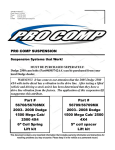
400 W. Artesia Blvd. Compton, CA 90220 Fax: (310) 747-3912 Ph: 1-800-776-0767 E-Mail: [email protected] Website: www.procompusa.com Latest Revision: 7.25.15 PRO COMP SUSPENSION IMPORTANT!: 18” AND LARGER WHEEL, NOT TO EXCEED 9” IN WIDTH WITH A MAXIMUM BACKSPACING OF 5 1/2” MUST BE USED IN CONJUNCTION WITH THIS LIFT KIT! See pg. 4 for details. K4190B 52222B 2015 FORD F150 2WD LIFT KIT This document contains very important information that includes warranty information and instructions for resolving problems you may encounter. Please keep it in the vehicle as a permanent record. 52222B Revised 7.25.15 Box 1 of 4-PN 52222B-1 Part # Description Qty. Illus. Page 91-10457 REAR CROSSMEMBER 1 3,4 6 91-10468 SWAY BAR DROP: Drvr 1 4 6 95-300F 3" LIFT BLOCK 2 9 11 91-5574 REAR BUMP STOP DROP 4 10 12 91-5575 STRUT SPACER SHIM 2 7 8 90-6701 71-181502501000 72-01810932 73-01810934 HARDWARE PACK: Rear Crossmember 18mm-2.5 X 150mm HEX BOLT 10.9 18mm-2.5 STOVER NUT Gr. C 18mm USS FLAT WASHER 2 1 1 2 5 5 5 7 7 7 90-6703 90-3085 97-120 72-050100811 HARDWARE PACK: Leaf Spring Shim Pack FORD REAR END SHIMS 1/2" X 3 1/2" GR. 8 USS. HEX MACHINED HEAD 1/2" GR. 8 USS UNPLATED HEX NUT 1 4 4 4 - - 90-6314 70-0311001800 72-031100816 73-03100838 70-0371501800 72-037100816 73-03700034 HARDWARE PACK: Rear Bump stop Drops 5/16” X 1 HEX BOLT GR. 8 5/16” STOVER NUT GR. C 5/16” USS FLAT WASHER 3/8” X 1 1/2” HEX BOLT GR. 8 3/8” STOVER NUT GR. C 3/8” HARDENED FLAT WASHER 1 1 1 2 2 2 4 10 10 10 12 12 12 1 2 2 2 1 2 2 - - 90-6569 HARDWARE PACK: Carrier Bearing Shim Kit 90-1080 3/8" SHIM 90-1081 1/4" SHIM 90-1082 1/8" SHIM 90-6013 HARDWARE PACK: Carrier Bearing Shim Kit 70-04322501800 7/16” x 2 1/4” USS GRADE 8 BOLT 73-04300042 7/16 USS HARDENED WASHER Box 2 of 4-PN 52221B-2 90-40032 KUCKLE: Drvr 1 - - 90-40033 KUCKLE: Pass 1 - - 90-6299 70-0311001500 72-03100100512 73-03100030 HARDWARE PACK: Front Brake Lines 5/16" X 1" Gr. 5 HEX BOLT 5/16" NYLOCK NUT 5/16" SAE FLAT WASHER 1 2 2 4 - - 91-10106 BRAKE LINE RELOCATOR: Front Knuckle 2 - - Box 3 of 4-PN 52222B-3 91-10453 FRONT CROSSMEMBER 1 2 6 91-10471 SWAY BAR DROP: Pass 1 4,6 6,7 13-90390 U-BOLT: 9/16"-18 x 3.36" x 12.50" 4 9 11 2 52222B Revised 7.25.15 Part # Description Qty. Illus. Page 91-10110 EMERGENCY BRAKE BRACKET 1 9 11 91-5502 REAR BRAKE LINE DROP 1 - - 90-6915 70-0371501800 72-037100816 73-03700034 HARDWARE PACK: Brake Line Drop/ Bump Kit 3/8” X 1” HEX BOLT Gr.8 3/8” STOVER NUT Gr. C 3/8” USS FLAT WASHER 1 2 2 4 8 8 8 10 10 10 90-6393 90-3202 HARDWARE PACK: Front Brake Line Drops F150 BRAKELINE DROP 1 2 - - 90-6299 70-0311001500 72-03100100512 73-03100030 HARDWARE PACK: Front Brake Lines 5/16" X 1" Gr. 5 HEX BOLT 5/16" NYLOCK NUT 5/16" SAE FLAT WASHER 1 2 2 4 - - 90-6340 70-0431751800 72-043100816 73-04300830 HARDWARE PACK: Sway Bar Drop 7/16” X 1 1/4" HEX BOLT Gr. 8 7/16” STOVER NUT Gr. C 7/16” SAE FLAT WASHER 1 4 4 8 4,6 4,6 4,6 6,7 6,7 6,7 90-6319 10999 HARDWARE PACK: Zip Ties ZIP TIE, 11", BLACK 1 12 - - 90-6751 90-5532 90-5533 90-6313 72-01810932 73-01810934 HARDWARE PACK: Cam Bolts CAM ECCENTRIC: F-150 Slotted CAM BOLT– Front: 18mm-2.5 X 150mm 10.9 HARDWARE PACK: Crossmember 18mm STOVER NUT 18mm FLAT WASHER 1 4 4 1 4 4 5 5 5 5 7 7 7 7 20-65302 HARDWARE PACK: 9/16” HI-NUTS 1 9 11 Box 4 of 4-PN 52213B-4 932008 9000 SERIES SHOCK 2 - - 91-2977 STRUT SPACER 2 7 8 90-6317 72-043200810 73-04300830 73-04300836 HARDWARE PACK: Spacer Mount 7/16” GR. 8 HEX NUT 7/16” SAE FLAT WASHER 7/16” SPLIT LOCK WASHER 1 6 6 6 7 7 7 8 8 8 Special Tools: Please refer to your service manual for more information. A special removal tool is required for safe removal of the tie rods. (PN T64P-3590-F). These tool may be purchased at your local Ford dealer. You may be able to rent any of these tools at your local parts store. 3 52222B Revised 7.25.15 Notice: This installation requires a professional mechanic! We recommend that you have access to a factory service manual for your vehicle to assist in the disassembly and reassembly of your vehicle. It contains a wealth of detailed information. Prior to installation, carefully inspect the vehicle’s steering and driveline systems paying close attention to the tie rod ends, ball joints, wheel bearing preload, pitman and idler arm. Additionally, check steering-toframe and suspension-to-frame attaching points for stress cracks. The overall vehicle must be in excellent working condition. Repair or replace all worn or damaged parts! Read the instructions carefully and study the illustrations before attempting installation! You may save yourself a lot of extra work. Check the parts and hardware against the parts list to assure that your kit is complete. Separating parts according to the areas where they will be used and placing the hardware with the brackets before you begin will save installation time. Check the special equipment list and ensure the availability of these tools. Secure and properly block vehicle prior to beginning installation. Always use NEW cotter pins on re-assembly! (These items are NOT supplied) ALWAYS wear safety glasses when using power tools or working under the vehicle! Use caution when cutting is required under the vehicle. The factory undercoating is flammable. Take appropriate precautions. Have a fire extinguisher close at hand. IT IS ADVISABLE THAT YOU HAVE HELP AVAILABLE WHEN INSTALLING THIS KIT. SOME COMPONENTS ARE HEAVY AND AWKWARD. ADDITIONAL HELP IS GOOD INSURANCE AGAINST INJURY! Foot pound torque readings are listed on the Torque Specifications chart at the end of the instructions. These are to be used unless specifically directed otherwise. Apply thread lock retaining compound where specified. Please note that while every effort is made to ensure that the installation of your Pro Comp lift kit is a positive experience, variations in construction and assembly in the vehicle manufacturing process will virtually ensure that some parts may seem difficult to install. Additionally, the current trend in manufacturing of vehicles results in a frame that is highly flexible and may shift slightly on disassembly prior to installation. The use of pry bars and tapered punches for alignment is considered normal and usually does not indicate a faulty product. However, if you are uncertain about some aspect of the installation process, please feel free to call our tech support department at the number listed on the cover page. We do not recommend that you modify the Pro Comp parts in any way as this will void any warranty expressed or implied by the Pro Comp Suspension company. If you use traction bars, ES9000 shocks may hit the traction bar mount, if it does a MX6 Series shock should be used. Tire & Wheel Information: Due to differences in manufacturing, dimensions and inflated measurements, tire and wheel combinations should be test fit prior to installation. Tire and wheel choice is crucial in assuring proper fit, performance, and the safety of your Pro Comp equipped vehicle. For this application, a 18” or larger wheel not to exceed 9” in width with a maximum backspacing of 5 1/2” is acceptable. A quality tire of radial design, not exceeding 35” tall X 13.5” wide is recommended. Please note that the use of a 35” X 13.5” tire may require fender modification. Violation of these recommendations will not be endorsed as acceptable by Pro Comp Suspension and will void any and all warranties either written or implied. IMPORTANT!: 18” OR LARGER WHEELS MUST BE USED IN CONJUNCTION WITH THIS LIFT KIT! 4 52222B Revised 7.25.15 Front Installation: 11. Remove the upper ball joint nut from the knuckle and separate using the appropriate tool. 1. Prior to installing this kit, with the vehicle on the ground. Measure the height of your vehicle. This measurement can be recorded from the center of the wheel, straight up to the top of the inner fender lip. Record the measurements below. LF: LR: 12. Remove the lower ball joint nut, separate using the appropriate tool. Remove the knuckle from the vehicle and set the knuckle aside. RF: 13. Remove the three OE nuts from the top of the strut assembly and the two OE nuts on the bottom. Remove the strut assembly from the vehicle. Save hardware for reinstallation. RR: 2. Ensure that your work space is of adequate size and the work surface is level. Place the vehicle in park and set parking brake. Place blocks both in front of and behind the rear wheels. Place your floor jack under the front cross member and raise vehicle. Place jack stands under the frame rails behind the front wheel wells and lower the frame onto the stands. Remove the jack and remove the front wheels. 14. Remove the two bolts that retain the lower a-arms and remove them from the truck. 15. Repeat on the other side of the vehicle. 16. Remove the rear cross member brace; retain the (4) OE bolts and nuts for reinstallation. See Illustration 1. NOTE: Careful heating of the OE bolts may be necessary to loosen the factory thread locker. 3. Remove any skid plates if necessary. 4. Work on one side of the vehicle at a time. 17. Install the front cross member (91-5519) into original front A-arm mounting locations, using the factory bolts with the heads to the front, leave loose. See Il- 5. Unbolt the OE brake line and bracket from the side of the knuckle. Save the hardware for reinstallation. 6. Remove the front caliper and bracket assembly from the front knuckle by removing the (2) retaining bolts. NOTE: Make sure you do not let the calipers hang on the brake lines or damage will occur. Illustration 1 OE Crossmember Brace Removal 7. Remove the front rotors from the front hub. 8. Disconnect the sway bar end links from the sway bar. Save hardware for reinstallation. Frame 9. Unbolt and remove the sway bar from the vehicle. Save hardware for reinstallation. OE Crossmember Brace 10. Remove the tie rod end nut and separate from the knuckle using the appropriate tool. 5 52222B Revised 7.25.15 Illustration 2 Illustration 3 Front Crossmember Install Rear Crossmember Install OE Bolt OE Bolt 91-10457 Rear Crossmember 91-10453 Front Crossmember Leave the bolts loose. See Illustration 3. lustration 2. 18. Raise the rear crossmember (91-10457) into place and install the (4) OE crossmember support brace bolts into the (4) crossmember brace holes on the drvr and pass side of the rear crossmember. 19. Install the sway bar drop brackets (9110468 drvr and 91-10471 pass) using the supplied 18mm X 150mm crossmember bolts. Install the bolts with the heads Illustration 4 91-10468 Sway Bar Drop drvr 7/16” X 1 1/4” Bolt Sway Bar Drop Bracket Install 91-10471 Sway Bar Drop Pass Existing OE Holes 91-10457 Rear Crossmember 18mm X 150mm Bolt 6 52222B Revised 7.25.15 Illustration 4. Illustration 5 A-Arm Install 90-5533 Cam Bolt 21. Install the lower a-arms into the new cross members with the supplied cam bolts (90-5533), cam eccentric (90-5532), 18mm washers and nuts. The cams should fit between the cam guides on the cross members. Center the cams in the guides. You will torque the bolts at the end of the install when the vehicle is on the ground. See Illustration 5. 90-5533 Cam Bolt 22. Torque all crossmember and sway bar hardware according to the torque chart on page 15 or to manufacturers specifications. 23. Transfer all the parts (except the OE dust shields) from the factory knuckles to the supplied Pro Comp knuckles (9040032 drvr and 90-40033 pass). NOTE: Tighten all the factory hardware carefully. Be sure to follow the factory assembly procedures and torque specifications. Lower A-Arm to the front. Leave the bolts loose. See Illustration 4. 20. Secure the sway bar drop brackets (915565 drvr and 91-5518 pass) to the OE sway bar mounting holes in the frame using the supplied 7/16” X 1 3/4” bolts and hardware. Leave the bolts loose. See OE Bolt Plate 24. Install the sway bar frame mounts to the sway bar drop brackets using the previously removed OE bolt plate and hardware. See Illustration 6. 25. Secure the sway bar end links to the sway bar using the previously removed OE hardware. 91-10471 Sway Bar Drop Pass 26. Torque the sway bar mount hardware to 60 ft./lbs. Sway Bar 27. WITH THE STRUT SPACERS, attach the spacer (91-2977) to the top of the OE strut assembly using the previously removed OE hardware. See Illustration 7. NOTE: The notch in the bottom ring will face toward the rear of the vehicle on the driver side and toward the front of the vehicle on the passenger side. 28. For additional lift, install the strut spacer shim (91-5575) onto the strut spacer (912977) studs and install the strut assembly into the strut mounting locations. Secure OE Nuts Illustration 6 Sway Bar Install 7 52222B Revised 7.25.15 Illustration 7 90-6317 7/16” Hardware With strut spacer 91-5575 Strut Spacer Shim OE Hardware 91-2977 Strut Spacer Notch Toward Rear OE or ZX2069 Coil Over Shock OE Nuts using the 7/16” supplied hardware on the top from hardware pack (90-6317). Torque to 45-50 ft./lbs. See Illustration 7. Illustration 7. Torque to factory specifications. 30. Repeat steps 27 through 29 on the remaining side of the vehicle. 29. Position the studs of the lower mount into the lower A-arm and secure with the previously removed OE nuts. See 31. Remove stock brake line bracket from frame. Carefully remount the brackets with the supplied brake line drops (908 52222B Revised 7.25.15 43. Recheck all hardware for proper installation and torque at this time. 3202 drvr and pass) in between bracket and frame. Use factory hardware to fasten the shorter end of the bracket to the frame. Position the drops, best for your application. Use the supplied hardware from pack (90-6299) to fasten OE bracket to the new brake line drop. 44. On both sides of the vehicle, check the routing of the brake lines and the ABS wire harnesses. There must be no pinching, rubbing, or stretching of either component. Use zip ties to secure these items. At full droop, cycle the steering from lock to lock while observing the reaction of these components. Reposition them if needed. WARNING!: Make sure the brake lines that you just modified are not resting against any moving parts. 32. Support the lower A-arms. Position the new front knuckles. Attach the knuckle to the lower ball joint. Torque to 111 ft./lbs. IMPORTANT! BE SURE TO BRING THE VEHICLE IMMEDIATELY TO A REPUTABLE ALIGNMENT SHOP TO BE ALIGNED! 33. Attach the knuckle to the upper ball joint. Torque to 85 ft./lbs. IMPORTANT! SOME 2WD LONG BED VERSIONS MAY NOT NEED TO HAVE THE STRUT SPACER SHIMS (915575) INSTALLED. IF THE FRONT OF YOUR VEHICLE MEASURES LESS THAN 28” TALL FROM THE HUB CENTER LINE TO THE EDGE OF THE WHEEL WELL, ADD STRUT SPACER SHIM (91-5575) TO ACHIEVE THE DESIGNED RIDE HEIGHT OF 28 1/2” (+/- 3/8”) 34. Connect the anti-lock wiring harness and sensor to the hub. 35. Attach the OE dust shields to the knuckle using the previously removed OE bolts. 36. Install the supplied brake line relocator (91-10106) to the upper hole in the knuckle, with the hole facing downward, using the previously removed OE bolt. 39. Install the front calipers on to the front rotors by reinstalling the retaining bolts. Torque to factory specifications. Install the tie rod end to the knuckle. Torque to 111 ft./lbs. IMPORTANT!: AFTER INSTALLATION OF KIT AND BEFORE THE VEHICLE IS FIRST STARTED, BE SURE TO CENTER THE FRONT WHEELS AND THE STEERING WHEEL. IF THE FRONT WHEELS AND THE STEERING WHEEL ARE NOT CENTERED BEFORE STARTING THE VEHICLE, IT MAY TRIGGER A DIAGNOSTIC TROUBLE CODE THAT WILL HAVE TO BE RESET BY THE MANUFACTURERS SERVICE FACILITY. 40. Repeat the installation on the other side of the vehicle. NOTE: SEE PAGE 13 FOR STEERING STOP ADJUSTMENT INSTRUCTIONS 37. Secure the OE brake line bracket on the front brake line to the new relocator (9110106) using the 5/16” X 1” bolt and hardware. 38. Install the front rotors on to the front hub. 41. Reinstall the wheels and tires and lower the vehicle to the ground. Torque the factory wheels to 150 ft./lbs. If you are using aftermarket wheels follow the manufacturers recommended specifications. 42. Torque the 18mm cam bolts to 180-200 ft./lbs. 9 52222B Revised 7.25.15 Rear Installation: axle pad, making sure the pins are fitted into the holes on the spring perch. Use your floor jack to raise the axle to the spring making sure the tabs on the spring block fit into the holes on the lift block. See Illustration 9. 1. Block the front tires and raise the rear of the vehicle. Support the frame with jack stands forward of the rear springs. 2. Remove the rear wheels. 3. Remove the shocks on both sides of the vehicle. It may be necessary that you slightly raise the axle to unload the shocks for removal. 13. Secure the assembly with the U-bolts (13-90390) supplied in hardware pack and new high-nuts and washers from hardware pack (20-65302). Do not tighten the U-bolts at this time. See Illustration 9. NOTE: Make sure the block sits flush on the axle perch. 4. Unbolt the emergency brake line mount from the frame. Remove the OE bolt and clip-nut from the frame and save for reinstallation. 5. Bolt the emergency brake line drop bracket (91-10110) to the frame using the supplied 3/8” X 1” bolt and hardware. See Illustration 8. 14. Repeat the installation on the other side of the vehicle. 15. When the installation of the remaining side is complete, torque the U-bolts to 105 ft./lbs. 6. Secure the OE emergency brake line mount to the emergency brake line drop bracket (91-10110) using the previously removed OE bolt and clip-nut. See Illustration 8. 16. Remove the factory bump stops from the vehicle. Save the bolts for reinstallation. 7. On drivers side, unbolt the existing brake line bracket from the frame. Illustration 8 E-Brake Drop 8. Install the supplied brake line extension bracket (90-5502) to the frame using the previously removed OE hardware. Then bolt the factory bracket to the new bracket using the supplied 5/16” X 1” hardware from hardware pack (90-6314). E-Brake Drop Bracket 91-10110 9. Reroute rear ABS as necessary use the supplies zip ties to secure lines. 10. Support the rear axle with a floor jack and remove the U-bolts on the driver side. Loosen the U-bolts on the passenger side. OE Clip-Nut 11. Remove the factory lift block from the spring assembly. This will not be reinstalled. 3/8” X 1 Bolt OE Bracket 12. Install the lift block (95-300F) onto the 10 E-Brake Lines OE Bolt 52222B Revised 7.25.15 17. Assemble the bump stop drop halves (PN 91-5774) and install the OE bump stops to the bump stop drop assemblies using the supplied 3/8” X 1 1/2” bolts. See Illustration 10. NOTE: Be sure that the pins on the OE bump stops fit into the holes in the bump stop drop assemblies. both end of the shocks. 18. Install the bump stop drop assemblies (PN 91-5774) to the frame using the previously removed OE bolts. See Illustration 10. 22. Reinstall the wheels and tires and lower the vehicle to the ground. Torque the factory wheels to 150 ft./lbs. If you are using aftermarket wheels follow the manufacturers recommended specifications. 20. Install your new Pro Comp shocks (MX6166, 932008 or ZX2071 w/ shaft end up ) and torque this hardware to 66 ft./lbs. 21. Reinstall the wheels and tires and lower the vehicle to the ground. 19. Insert the supplied sleeves (60859) in Illustration 9 Block install U BOLT 13-90390 95-300F Lift Block 20-65302 Hi-Nuts 11 52222B Revised 7.25.15 Frame NOTES: Frame On completion of the installation, have the suspension and headlights re-aligned. After 100 miles recheck for proper torque on all newly installed hardware. Recheck all hardware for tightness after off road use. OE Bolt 91-5574 Bump Stop Drop Halves OE Bump Stops Illustration 10 Rear Bump Stop Drop Assembly 3/8” X 1 1/2” Bolt NOTE: If you wish to raise the ride height of the rear of the vehicle, Install the rear leaf spring shims from hardware pack (90-6703) using the enclosed instructions. 23. Recheck all hardware for proper installation and torque at this time. NOTE: If driveshaft vibration occurs, install the carrier bearing shim kit (90-6569) using the 3/8” X 1 1/2” bolts and hardware from pack (906013). Not all vehicles will use the same combination of shims. Only by driving the vehicle and adding or removing shims can the vibration be eliminated. 12 52222B Revised 7.25.15 PRO COMP SUSPENSION Suspension Systems that Work! Steering Stop Shim Adjustment Instructions: 1. After having the vehicle properly aligned by a qualified alignment shop, ensure that your work space is of adequate size and the work surface is level. Place the vehicle in park and set parking brake. Place blocks both in front of and behind the rear wheels. 2. With the vehicle on the ground make sure the steering wheel and the tires are straight. 3. Turn the steering wheel to full lock left and remove the appropriate shims from the passenger side front stop and the driver side rear stop until the steering wheel at full lock is in the same position as Illustration A. 4. Turn the steering wheel to full lock right and remove the appropriate shims from the driver side front stop and the passenger side rear stop until the steering wheel at full lock is in the same position as Illustration B. 5. Be sure to use thread locking compound on the 5/16” X 1” shim retaining bolts. See Illustration C. Full Lock Left Full Lock Right Illustration A Illustration B Full Lock Left Full Lock Right 20 deg. 20 deg. IMPORTANT!: Any more steering angle than shown in the illustrations may result in CV failure. 13 52222B Revised 7.25.15 Illustration C Shim Installation i ck Lo ad n d re o u Th omp C ng Steering Knuckle Steering Stop Shims 5/16” X 1” Bolts Steering Stop Shims Note: This Illustration is just a representation and every application will be different 14 52222B Revised 7.25.15 Revision Page: 15 52222B Revised 7.25.15 The PRO COMP PROMISE WARRANTY At Pro Comp, we know you have many choices when selecting products to personalize your vehicle. You should demand nothing but the highest quality available and have total confidence that the products you selected are the best in the industry. It is for these reasons that Pro Comp Suspension products are backed by the best warranty in the industry...the Pro Comp Promise! Pro Comp promises that its products will last a lifetime or we will replace it free of charge. It’s that simple! Because of our commitment to quality and manufacturing excellence, we are able to stand behind our products. FOREVER. It is Pro Comp’s Promise that if one of our suspension products breaks not due to misuse, neglect or vandalism, we will replace it. Whether you are the original purchaser or not, you can be assured that we will make it right. The Pro Comp Promise covers all suspension products including shocks and steering stabilizers. Buy Pro Comp Suspension today and enjoy it for the rest of your life! That’s our Pro Comp Promise! Notice to Owner, Operator, Dealer and Installer: Vehicles that have been enhanced for off-road performance often have unique handling characteristics due to the higher center of gravity and larger tires. This vehicle may handle, react and stop differently than many passenger cars or unmodified vehicles, both on and off–road. You must drive your vehicle safely! Extreme care should always be taken to prevent vehicle rollover or loss of control, which can result in serious injury or even death. Always avoid sudden sharp turns or abrupt maneuvers and allow more time and distance for braking! Pro Comp reminds you to fasten your seat belts at all times and reduce speed! We will gladly answer any questions concerning the design, function, maintenance and correct use of our products. Please make sure that the Dealer / Installer explains and delivers all warning notices, warranty forms and instruction sheets included with Pro Comp product. Warranty and Return Policy: Pro Comp warranties its full line of products to be free from defects in workmanship and materials for the life of the product. Pro Comp’s obligation under this warranty is limited to repair or replacement, at Pro Comp’s option, of the defective product. Any and all costs of removal, installation, freight or incidental or consequential damages are expressly excluded from this warranty. Pro Comp is not responsible for damages and / or warranty of other vehicle parts related or non-related to the installation of Pro Comp product. A consumer who makes the decision to modify his vehicle with aftermarket components of any kind will assume all risk and responsibility for potential damages incurred as a result of their chosen modifications. Warranty coverage does not include consumer opinions regarding ride comfort, fitment and design. Warranty claims can be made directly with Pro Comp or at any factory authorized Pro Comp dealer. IMPORTANT! To validate the warranty on this purchase please be sure to mail in the warranty card. Claims not covered under warranty * Parts subject to normal wear; this includes bushings, bump stops, ball joints, tie rod ends and heim joints. * Finish after 90 days. * Damage caused as a result of not following recommendations or requirements called out in the installation manuals. Pro Comp MX Series coil-over shocks are considered a serviceable shock with a one-year warranty against leakage only. Rebuild service and replacement parts will be available and sold separately by Pro Comp. Contact Pro Comp for specific service charges. Pro Comp accepts no responsibility for any altered product, improper installation, lack of or improper maintenance or improper use of our products. E-Mail: [email protected] Website: www.procompusa.com Fax: (310) 747-3912 Ph: 1-800-776-0767 PLACE WARRANTY REGISTRATION NUMBER 16 HERE: __________________