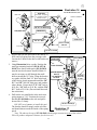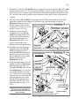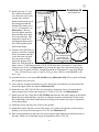
1
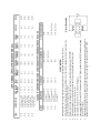
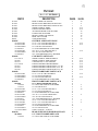
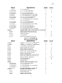
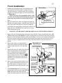
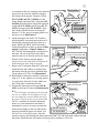
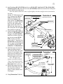
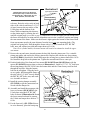
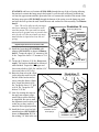
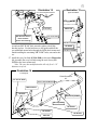
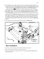
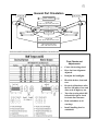
2360 Boswell Road
Chula Vista, CA 91914
Phone
619.216.1444
Fax
619.216.1474
E-Mail
[email protected]
PRO COMP SUSPENSION
Suspension Systems that Work!
Part # 55099 87 - 95 YJ, Wrangler
Coil Spring Suspension System
This document contains very important information that includes warranty information and instructions for
resolving problems you may encounter. Please keep it in the vehicle as a permanent record.
55099
Revised
12.5.05
Special Notes:
♦
This kit will NOT fit right hand drive vehicles.
♦
This kit is for vehicles equipped with power steering only.
♦
A transfer case slip yoke conversion is required for this Pro Comp Suspension system. Correct rear drive
shaft angles can only be obtained by elimination the slip yoke and replacing it with a CV joint. The
following Pro Comp kits are recommended. More detailed information is available on the next page:
◊ 4007
Tail shaft conversion kit. (NP231 transfer case only)
◊ 4040
CV Style drive shaft.
◊ 4041
CV Style drive shaft.
♦ Installation of this suspension conversion allows for the use of larger tires. This along with the
increase in ground clearance raises the center of gravity and will greatly affect the stability and
handling of your vehicle both on and off highway. It is very important that you familiarize yourself
with the new handling characteristics of your vehicle before driving at speeds above 25 mph either
off road or on the highway. In addition, the vehicle will have moderate torque steer. (This means
that it will pull slightly from side to side under acceleration and deceleration). This is a natural side
effect of lifted coil
spring vehicles.
Recommended Tires and Wheels
Due to
differences in
manufacturing,
dimensions and
inflated measurements, tire and wheel combinations should be test fit prior to installation. Tire and
wheel choice is crucial in assuring proper fit, performance, and the safety of your Pro Comp equipped
vehicle. For this application, we recommend a wheel not to exceed 8” in width with a minimum
backspacing of 4” must be used, additionally, a quality tire of radial design, not exceeding 35” tall X
12.5” wide is also recommended. Please note that the use of a 35” X 12.5” tire may require fender
modification. Violation of these recommendations will not be endorsed as acceptable by Pro Comp
Suspension and will void any and all warranties either written or implied.
Introduction:
♦
♦
♦
♦
♦
♦
♦
♦
♦
♦
This installation requires a professional mechanic!
We recommend that you have access to a Jeep YJ service manual for your vehicle to assist in the
disassembly and reassembly of your vehicle. It contains a wealth of detailed information.
Prior to installation, carefully inspect the vehicle’s steering and driveline systems paying close attention to
the tie rod ends, ball joints, wheel bearing preload, pitman and idler arm. Additionally, check steering-toframe and suspension-to-frame attaching points for stress cracks. The overall vehicle must be in excellent
working condition. Repair or replace all worn or damaged parts! Additionally, very close attention must be
given to the condition of the rear axle spring pads. Spring pads that are not perfectly flat must be repaired
or replaced. Use only a factory replacement pad. Pro Comp kits use the spring pad as a mounting surface.
Read the instructions carefully and study the illustrations before attempting installation! The more familiar
you are with the procedures, the easier and quicker your installation will be.
Check the parts and hardware against the parts list to assure that your kit is complete. Separating parts
according to the areas where they will be used and placing the hardware with the brackets before you
begin will save installation time.
Secure and properly block vehicle prior to beginning installation.
ALWAYS wear safety glasses when using power tools or working under the vehicle!
NEVER work under or around an unsupported vehicle.
Use caution when cutting is required under the vehicle. The factory undercoating is flammable. Take
appropriate precautions. Have a fire extinguisher close at hand.
Foot pound torque readings are listed on the Torque2 Specifications chart at the end of the instructions.
These are to be used unless specifically directed otherwise.
5.0”/5.0”
5.0”/5.0”
DESCRIPTION
YJ Wrangler 4WD
4 cylinder
YJ Wrangler 4WD
6 cylinder
YJ Wrangler 4WD
4 cylinder
YJ Wrangler 4WD
6 cylinder
YEAR
87-95
Incl.
Incl.
Incl.
Incl.
55095
55095
55095
55095
Incl.
Incl.
Incl.
Incl.
FRONT COIL TIE DOWN REAR COIL
SPRINGS
RINGS
SPRINGS
5.0”/5.0”
5.0”/5.0”
5.0”/5.0”
5.0”/5.0”
RIDE HEIGHT
YJ CSC NOTES:
4007
4007
4007 (See Notes)
4007 (See Notes)
TAIL SHAFT CONVERSION KIT
This kit is designed to work with the factory Dana 35 rear axle and the Dana 30 front axle.
The required tire size is 33” X 12.5” X 15”.
The required rim size is a 15” X 8” with 3.5” backspace.
♦
♦
♦
Incl.
Incl.
Incl.
Incl.
PITMAN
ARM
3
Incl.
Incl.
Incl.
Incl.
SHOCKS
K3053
K3052
K3051
K3050
REF #
Measure
here
U-Joint Illustration
4041 (See Notes)
4041 (See Notes)
4040
4040
C/V STYLE DRIVESHAFT
The driveshaft, PN 4041, uses a U-joint 3 5/8” from cap to cap and is the most common. Some vehicles may be
equipped with the smaller U-joint measuring 3 1/4” from cap to cap and will require driveshaft PN 4040.
Conversion kit 4007 is for the NP231 transfer case ONLY. The kit will not fit the NP207 transfer case found
in some 1987 models.
Stainless steel tie down rings bolt to the front factory shackle hanger kit mounts (PN 55095)
Lift achieved and vehicle stance will vary according to how the vehicle is equipped (motor, top, accessories,
etc.) these can affect driving characteristics.
♦
♦
Incl.
Incl.
Incl.
Incl.
BRAKE
LINE KIT
This kit includes the steering stabilizer and provisions for re-installation of the factory sway bar.
87-95
87-95
87-95
55199
55099
55194
55094
FRONT
KIT
♦
♦
♦
87-95
87-95
5.0”/5.0”
5.0”/5.0”
RIDE HEIGHT
FRT/REAR
TAILSHAFT CONVERSION KIT AND CV DRIVESHAFT OPTIONS REQUIRED FOR CSC KIT
YJ Wrangler 4WD
4 cyl w/soft top
YJ Wrangler-4WD
4 cyl w/hard top
YJ Wrangler 4WD
6 cyl w/soft top
YJ Wrangler-4WD
6 cyl w/hard top
87-95
87-95
DESCRIPTION
YEAR
JEEP YJ WRANGLER COIL SPRING CONVERSION (CSC)
55099
Revised
12.5.05
Part List:
Box 1 of 5 PN 55099-1
PART#
DESCRIPTION
QUAN.
ILLUS.
10
9
9
6, 19
5, 18
10
10
10
17
10
90-1020
90-1022
90-1023
90-1039
90-1040
90-1045
90-1050
90-1059
90-1068
654031
REAR LOWER COIL MOUNT
FRONT TRACK BRACKET, REAR PLATE
FRONT TRACK BRACKET, FRONT PLATE
UPPER CONTROL ARMS
LOWER CONTROL ARMS
ALUMINUM BUMP STOP SPACERS
LOWER COIL RETAINER
FRONT LOWER COIL MOUNT
REAR AXLE CLAMP
CONE BUMPSTOPS
2
1
1
4
4
4
4
2
2
4
90-6005
CONTROL ARM PARTS PACK
1
1/2” X 3 1/4” USS GR 8 HEX BOLT
1/2” X 3 3/4” USS GR 8 HEX BOLT
1/2” USS GR 8 STOVER NUT
1/2” SAE HARDENED FLAT WASHER
9/16” X 4 1/2” NC GR 8 HEX BOLT
9/16” NC GD 8 STOVER NUT
9/16” SAE HARDENED FLAT WASHER
4
4
8
16
4
4
8
70-0503251800
70-0503751800
72-05000100816
73-05000034
70-0564501800
72-05600100816
73-05600034
90-6006
15-11252-A
90-2026
90-1051
15-11252-B
90-2027
90-2028
90-1049
90-6008
70-0503751800
72-05000100816
72-05000200816
73-05000034
90-6009
20-65991
13-30034
13-10332
70-0501251800
72-05000100816
73-05000034
70-0433751800
72-04300100816
73-04300034
70-0371751800
70-0371501800
72-03700100816
73-03700034
72-03700100512
71-120301758800
90-6010
20-65991
13-30034
CAM BOLT PARTS PACK
1
UPPER CONTROL ARM BUSHINGS
UPPER CONTROL ARM SLEEVES
CAM SPACER, 1/2” ID, GROUND
LOWER CONTROL ARM BUSHINGS
LOWER CONTROL ARM SLEEVES, 1/2” ID
LOWER CONTROL ARM SLEEVE, 9/16” ID
LOWER CONTROL ARM SPACER, 9/16” ID
16
8
8
16
4
4
8
FRONT HARDWARE PARTS PACK
1
1/2” X 3 3/4” NC GR 8 HEX BOLT
1/2” NC GR 8 STOVER NUT
1/2” NF GR 8 STOVER NUT
1/2” SAE HARDENED FLAT WASHER
8
8
4
20
FRONT HARDWARE PARTS PACK
1
1/2” U-BOLT HARDWARE PACK
1/2” GR 8 UNPLATED FLAT WASHER
1/2” NF GR8 HI NUT
1/2” X 1 1/4” USS GR 8 HEX BOLT
1/2” NC GR 8 STOVER NUT
1/2” SAE HARDENED FLAT WASHER
7/16” X 3 3/4” USS GR 8 HEX BOLT
7/16” NC GR 8 STOVER NUT
7/16” SAE HARDENED FLAT WASHER
3/8” X 1 3/4” USS GR 8 HEX BOLT
3/8” X 1 1/2” USS GR 8 HEX BOLT
3/8” NC GR 8 STOVER NUT
3/8” SAE HARDENED FLAT WASHER
3/8” NC NYLOCK NUT
12mm X 30mm X 1.75, BOLT
1
8
8
5
5
11
4
4
8
3
2
5
12
2
1
REAR SUSPENSION HARDWARE PACK
1/2” U-BOLT HARDWARE PACK
1
1
1/2” GR 8 UNPLATED FLAT WASHER
8
4
6, 19
8, 19
5, 18
6, 19
6, 19
6, 19
5, 18
5, 18
5, 18
5, 18
5, 18
6, 19
2
2
10
4
2
9
3
2
55099
Revised
12.5.05
PART#
13-10332
70-0501251800
70-0503251800
72-05000100816
73-05000034
73-05000042
70-0433751800
72-04300100816
73-04300034
70-0371001800
72-03700100816
73-03700034
72-03700100512
70-0310751800
72-03100100816
73-0310034
96-6012
90-2025
54314
90-1079
41-8243T
90-2031
DESCRIPTION
1/2” NF GR8 HI NUT
1/2” X 1 1/4” GR 8 HEX BOLT
1/2” X 3 1/4” GR 8 HEX BOLT
1/2” USS GR 8 STOVER NUT
1/2” SAE HARDENED FLAT WASHER
1/2” USS HARDENED FLAT WASHER
7/16” X 3 3/4” USS GR 8 HEX BOLT
7/16” USS GR 8 STOVER NUT
7/16” SAE HARDENED FLAT WASHER
3/8” X 2” USS STUD
3/8” X 1” USS GR 8 HEX BOLT
3/8” USS GR 8 STOVER NUT
3/8” SAE HARDENED FLAT WASHER
3/8” USS GR 5 NYLOCK NUT
5/16” X 3/4” USS GR 8 HEX BOLT
5/16” USS GR 8 STOVER NUT
5/16” SAE HARDENED FLAT WASHER
QUAN.
ILLUS.
8
4
1
5
10
2
4
4
8
4
2
2
8
10
1
1
2
2
10
16
20
17
16
17
16
HARDWARE PACK-CAMS, SLEEVES, SPACERS 1
FRONT TRACK BRACKET SPACER
SHOCK SLEEVE-1/2” X 5/8” X 1.480”
SHOCK ADAPTER
YJ CAM BOLT
REAR TRACK BRACKET SPACER
1
2
2
4
1
9
13
13
6, 19
16
QUAN.
ILLUS.
2
18
2
Box 2 of 5 PN 55099-2
PART#
DESCRIPTION
13-90481
13-90496
13-90504
219201
90-1053
90-1054
90-1055
90-1063
90-1065
90-1069
90-1072
90-1073
90-1076
90-1095
90-2008
YJ400-1
U-BOLT, 1/2” X 3.3” X 6” - LARGE, FRONT
U-BOLT, 1/2” X 3.062 X 4 1/2” - REAR
U-BOLT, 1/2” X 3.062 X 6” - SMALL FRONT
YJ STEERING STABILIZER KIT
REAR LOWER U-BOLT PLATE
REAR UPPER COIL MOUNT
FRONT UPPER COIL MOUNT
FRONT AXLE CLAMP, PASSENGER
FRONT AXLE CLAMP, DRIVER
FRONT U-BOLT PLATE
REAR TRACK BRACKET, FRONT PLATE
REAR TRACK BRACKET, REAR PLATE
FRONT & REAR CAM MOUNT
LOWER LINK MOUNT
SWAY BAR LINK
PITMAN ARM
2
4
2
1
2
2
2
1
1
2
1
1
4
2
2
1
90-6007
SHOCK ADAPTER PARTS PACK
1
1/2” X 2 3/4” GR 5 HEX BOLT
1/2” NYLOCK NUT
1/2” SAE HARDENED FLAT WASHER
5/8” NYLOCK NUT
5/8” USS HARDENED FLAT WASHER
2
2
4
2
2
BRAKE LINE PARTS PACK
1
FRONT BRAKE LINE KIT
REAR BRAKE LINE
BRAKE LINE BRACKET
BRAKE LINE CLAMP KIT
2
1
2
1
70-0502751500
72-05000100512
73-05000100512
72-06200100512
73-06200032
90-6011
7425-A
7425-E
90-1031
7425-P
5
17
20
7
2, 3
2, 3
2
16
16
6, 8, 19
12
13
13
55099
Revised
12.5.05
PART#
90-6035
90-2053
90-2054
45359
51792
90-6043
70-0502501800
72-05000100816
73-05000034
70-0370751800
37F200SCB
72-03700100816
37FNCB
73-03700034
31C25KKC
DESCRIPTION
QUAN.
SWAY BAR KIT
1
SWAY BAR SLEEVE
SWAY BAR COLLAR
5/8” HOURGLASS BUSHING
SLEEVE - 5/8” X 1/2” X 1.350”
1
2
4
2
SWAY BAR HARDWARE PACK
1
1/2” X 2 1/2” GR 8 HEX BOLT
1/2” USS GR 8 STOVER NUT
1/2” SAE HARDENED FLAT WASHER
3/8” X 3/4” GR 8 HEX BOLT
3/8” X 2” SAE 12 POINT BOLT
3/8” GR 8 STOVER NUT
3/8” 12 POINT NUT
3/8” SAE HARDENED FLAT WASHER
5/16” X 1/4” ALLEN SET SCREW
2
2
4
6
2
6
2
12
2
ILLUS.
14
14
14
14
14
12
14
14
14
Box 3 of 5 PN 55099-3
PART#
55596-1
DESCRIPTION
YJ FRONT COIL
QUAN.
ILLUS.
2
10
QUAN.
ILLUS.
2
10
QUAN.
ILLUS.
2
2
13
13
Box 4 of 5 PN 55099-4
PART#
55594-1
DESCRIPTION
YJ REAR COIL
Box 5 of 5 PN 55099-5
PART#
926500
923500
DESCRIPTION
YJ FRONT SHOCK
YJ REAR SHOCK
6
55099
Revised
12.5.05
Front Installation:
1. Measure the front pinion angle at ride height and on
level ground. Record this angle for future reference.
This measurement is in degrees and will be needed to
properly set up the front upper arm cam mounts. Refer
to Illustration 1.
NOTE: This step is for unmodified vehicles. Vehicles with a previously installed aftermarket suspension
system may not provide an accurate angle for reference.
2. Raise the front of the vehicle and support the frame behind the front spring hangers with jack stands. Raise the
rear of the vehicle and support it with jack stands forward of the rear spring hangers. Having the vehicle level
during the entire installation will assist in the accuracy
of the pinion angle set up.
Illustration 1
Angle Gauge
See instruction #1
(Angle exaggerated for clarity)
WARNING: NEVER WORK UNDER OR AROUND AN UNSUPPORTED VEHICLE!
3. Remove the stock front brake lines and replace them with Pro Comp extended brake lines, (PN
7425-A) and brackets (PN 90-1031). Use the existing bolt to secure them in the factory location.
Be sure to clean the banjo mounting surface on the caliper. Use new crush washers and check for
sufficient clearance between the steering shaft and the factory brake line on the drivers side. It
may be necessary to slightly bend the lower lip of the inner fender to clear the brake line or
bracket.
4. Remove the wheels, steering stabilizer,
Illustration 2
Passenger Side Front
front shocks, and the track bar bolt where it
PN 13-90481
attaches to the front axle. Save this hardFront U-bolt
3/8” X 1 3/4” Bolts
ware.
(Large Radius)
5. Support the front axle with a floor jack and
remove the passenger side leaf spring, Ubolts, U-bolt plate, and sway bar link.
Loosen the driver side U-bolts but do not
remove them at this time. This will ease
alignment of the passenger side brackets
PN 13-90504
and allow you to maintain control of the
Front U-bolt
See instruction 8
(Small Radius)
axle assembly.
6. Remove the sway bar links from the sway
bar. Loosen the bolts that secure the sway
PN 90-1063, Pass
bar rubber mounts. Swing the sway bar
Typical Bolt tightening
PN 90-1069
PN 90-1065, Driver
sequence
down and finish removing it from the vehicle.
PN 13-30034
7. Using Illustrations 2 & 3 as reference, set
PN 13-10332
the passenger side front axle clamp (PN 901063) on the axle tube. Make sure the
clamp fits tightly against the axle tube. Due
7
4
2
1
3
55099
Revised
12.5.05
Illustration 3
to variations in the axle castings, some material
may need to be removed from the casting so
the clamp will fit properly. Drop the U-bolts
(PN 13-90481 and PN 13-90504) over the
clamp flanges and install the U-bolt plate (PN
90-1069) from the bottom. Install the hardened
washers (PN 13-30034) and Hi-Nuts (PN 1310332) from parts pack PN 20-65991. Align
the U-bolts with the brackets and snug the
bolts to 15 ft. lbs. using a crossing pattern. See
the inset view in Illustration 2.
8. On the passenger side, drill a 3/8” diameter
hole through the cast spring pad at the rear of
the housing using the lower axle clamp as a
guide. Install one 3/8” X 1 3/4” bolt with a
washer through the rear hole as shown in Illustration 2, and either a 12mm X 30mm or a
1/2” X 1 1/4” bolt through the existing hole in
the front. The size of the bolt used is determined by the size of the bolt used by the manufacturer for the factory steering damper.
On the drivers side, both holes will need to be
drilled using the axle clamp as a guide
9. Remove the U-bolt plate from the U-bolts and
install the nuts and washers as needed from
the bottom onto the previously installed bolts.
Torque them to 35 ft. lbs. See Illustration 3.
10. Reinstall the U-bolt plate with the U-bolts and
snug to 15 ft. lbs. Again use a crossing pattern
to evenly draw down the U-bolts. Make sure
the U-bolt plate is oriented as shown.
11. Position the front upper coil mount (PN 901055) on the frame as shown in Illustrations 4
& 7.
Passenger Side Front
PN 90-1063, Pass Side
PN 90-1065, Driver Side
12mm X 30mm OR
1/2” X 1 1/4” Bolt
See Instruction 8
Illustration 4
Front Shock Mount, Pass.
Remove material as needed to clear
the upper coil mount, PN 90-1055.
7/16” X 3 3/4” Bolts
PN 90-1055
26” Center to Center
PN 20-2028
Illustration 5
Typical Lower Control Arm
PN 90-1049
Note: The upper coil mounts for the front and
rear are very similar. The only difference is that
the rear mounts have a stop welded at the end of
the groove. The front groove is open at both sides.
PN 11252-B
PN 90-1049
The 26” centerline to centerline dimension
shown is a critical dimension and must be
PN 90-1040
maintained. It may be necessary to notch the
9/16” X 4 1/2” Bolt
shock mount slightly in the area indicated to
properly position the upper coil mount. (See
1/2” X 3 3/4” Bolt
PN 20-2027
the inset view in the illustration). Once the
mount is in place, drill through the frame and install 7/16” X 3 3/4” bolts with washers through
the mount. Install the nuts and washers and torque these fasteners to 30 ft. lbs.
8
55099
Revised
12.5.05
12. Install bushings (PN 15-11252-B) and sleeves (PN 90-2027 Axle End (1/2” ID), PN 90-2028
Frame End (9/16” ID) ) into all lower arms (PN 90-1040). Install one arm into the U-bolt plate
and rear OEM leaf spring mount.
Note:The radius on the lower arms is offset slightly, the short straight section is mounted to
the frame.
Use the 1/4” thick spacers with
Illustration 6
9/16” diameter hole (PN 901/2” NF Stover Nuts
Typical Upper Control Arm
ALL
CAM
BOLTS
1049) on both sides of the
PN 90-1076
lower arm bushings at the
frame mount. See Illustration
PN 90-1051
5. Install a new 9/16” X 4 1/2”
bolt, nut, and washer at the
frame mount and a 1/2” X 3
3/4” bolt, nut, and washer at
the U-bolt plate. Do not tighten
these fasteners at this time.
PN 11252-A
13. Install bushings (PN 11252-A)
and sleeves (PN 90-2026) into
PN 41-8243T
all upper arms (PN 90-1039).
Install one end into a front upPN 90-1039
per arm cam mount (PN 901076). Use the 1/4” thick
spacer with 1/2” diameter hole
(PN 90-1051) on both sides of
the rear upper arm bushing and
PN 90-2026
one cam bolt assembly (PN
41-8243T). See Illustration 6.
1/2” X 3 1/4” Bolt
14. Install the upper arm into the
front axle mount using the
1/2” X 3 1/4” bolts, nuts, and
Illustration 7
washers. Do not tighten. The
Passenger Side
upper arm cam mount will be
PN 90-1076
positioned and secured later,
PN 90-1055 - Front
Groove Open on Both Sides
just let it hang loose for now.
PN 90-1054 - Rear
Note: The upper cam
Groove Closed at one side
mounts are mounted with the
“long” tab oriented in the direction of the control arm. Use
26” - Front Axle
15 1/4” - Front Axle
Illustration 21 for reference.
26 1/2” - Rear Axle
and Rear Axle
15. Support the pinion to prevent
the axle from rolling over. Remove the driver side leaf
spring, U-bolts, shackles and
U-bolt plate.
16. Using Illustrations 7 & 8 for
9
55099
Revised
12.5.05
Illustration 8
Repeat steps 7 thru 14 on the driver
side except in step 7, both holes must
be drilled to 3/8”, and two 3/8” X 1 1/4”
bolts, washers, and nuts used.
Typical Upper Cam Mount
1/2” X 3 3/4” Bolts
reference, Raise the axle evenly on both
sides of the vehicle until there is 15 1/4”
of space between the top surface of the
PN 90-1076
U-bolt plate and the bottom of the
frame. While maintaining this distance,
set the pinion angle by rotating the axle
until the original angle (recorded in step 1) is duplicated. Locate the upper arm cam mount onto
the frame and adjust its location until the alignment cam is in the “centered” position and clamp
the cam mount to the frame. Make sure the mount is tight against the bottom of the frame. Both
front cam mounts must be the same distance from the lower rear arm mounting bolts. (The
original leaf spring bolt.) Drill through the frame with a 1/2” drill. Install the 1/2” X 3 3/4”
bolts, nuts, and washers provided and torque them to 65 ft. lbs.
Note: On 4 cylinder models, the motor mount will need to be trimmed to install the upper
cam mount.
17. Remove the nut and cotter pin and separate the drag link from the pitman arm. Use a suitable
pitman arm puller and remove the factory pitman arm. Replace this with the new drop pitman
arm (PN YJ400-1) from this kit. Install and torque the steering box to pitman shaft nut to 165 ft.
lbs. Install the drag link to the pitman arm. Tighten the nut and install a new cotter pin.
18. Position both sides of the front track bar mount (PN 90-1022 Front, 90-1023 Rear) with the
spacer (PN 90-2025) between them as shown in Illustration 9 . Install a 1/2” X 3 3/4” bolt from
the steering damper kit (PN 219201) into the bottom hole and the 12mm factory track bar bolt
through the top hole. Snug the bottom
bolt but do not tighten. Using the brackIllustration 9
ets as a guide, drill through the flange on
Front Track Bar Mount
the axle with a 3/8” drill. Loosely install
the 3/8” X 1 1/2” bolts, nuts, and washers. Assemble as shown.
19. Install the steering damper assembly
PN 90-2025
(PN 219201) as per the instructions enclosed with the damper kit.
20. Assemble and install the passenger side
PN 90-1022
lower coil mount (PN 90-1059) to the
U-bolt plate using the 1/2” X 1 1/4”
PN 90-1023
bolts as shown in Illustration 10. Rotate
the lower mount back until it contacts
PN 219201 Hardware
the U-bolts and torque these bolts to 75
3/8” X 1 1/2” Bolts
ft. lbs.
21. For the front coil, ((PN 55596-1) heavier wire diameter), place the bump stop
10
55099
Revised
12.5.05
(PN 654031) and lower coil retainer (PN 90-1050) through the top of the coil spring allowing
the retainer to restrain the bump stop at the bottom. Lower the axle sufficiently to thread the
coil into the upper mount until the open end of the coil contacts the outside of the mount. Slide
the bump stop spacer (PN 90-1045) through the bottom of the spring over the bump stop stud
and raise the axle up onto the stud. Install the nuts and washers to retain assembly. See Illustration 11.
Note: The coil is offset on the passenger
Illustration 10
side lower mount for coil clearance at the
Typical Spring Mount Assy.
track bar mount. The cast track bar mount
may need to be ground away to provide clearPN 654031
PN 90-1059, Front
ance for the coil. (Do not remove any more
PN 90-1020, Rear
PN 90-1050
material than is required to clear the coil
spring)
PN 90-1045
Repeat steps 20 and 21 on the driver side.
22. Install the front shock (PN 926500) with
adapters (PN 90-1079) as shown in Illustration 13. Torque the upper 5/8” mounts to 100
ft. lbs. Torque the lower 1/2” mounts to 75 ft.
lbs.
23. Torque the U-bolts to 45 ft. lbs. Do not over
torque! The bracket should not be deformed
when finished. Torque the 1/2” upper and
lower arm to bolts to 90 ft. lbs. and the 9/16”
lower arm bolts to 105 ft. lbs.
24. Raise the front axle with a floor
jack to align the track bar with
the hole in the bracket and secure it using the factory 12mm
bolt. Torque this bolt to 65 ft.
lbs. Torque the lower 1/2” bolt
to 90 ft. lbs. Torque the 3/8”
bolts to 35 ft. lbs.
25. Note: By rotating the cams on
the upper arm mounts, alignment of the track bar bolt may
be simplified. Be sure to mark
the alignment cam location prior
to this step so they can be returned to their original position.
Detail of Correct Spring
26. Install the lower sway bar link
Installation for the
Front Springs.
mount brackets (PN 90-1095) as
shown in Illustration 12. Use
the existing 3/8” hole in the cen11
1/2” X 1 1/4” Bolts
Illustration 11
Typical Upper Spring Mount
PN 55596-1, Front Coil
PN 55594-1, Rear Coil
55099
Revised
12.5.05
Illustration 12
Illustration 13
Front, Lower Sway Bar Link Mount
Typical Shock Mount
PN 90-1095
Drill two 3/8” holes in
these locations.
(Center hole existing)
PN 90-1079
3/8” X 3/4” Bolts
5/8” X 1 1/2” Bolts
ter and one 3/8” X 3/4” bolt, nut and washers to hold this
bracket in place. Use the bracket as a drill guide and drill the
two additional mount holes through the OEM shock mount and
finish installing the remaining 3/8” X 3/4” bolts, nuts and washers.
27. Install the sway bar links (PN 90-2008) as shown in Illustration
14. Assemble the sway bar links using the steel sleeve (PN
51792) at the lower mount end.
Note: The sway bar modification kit will only fit a 1 1/8”
diameter sway bar.
PN 926500
1/2” X 1 1/2” Bolts
Illustration 14
Front Sway Bar
Finish Dimension
38”
1/2” X 2 1/2” Bolts
5/16” X 1/4” Set Screws
OEM Hardware
PN 45359
3/8” X 2” 12 pt. Bolts
3/8” 12 pt. Nuts
PN 90-2053
PN 90-2008
PN 90-2054
PN 51792
12
55099
Revised
12.5.05
28. To modify the sway bar, measure to the center of the sway bar and cut through using an abrasive saw. Remove any rust and scale that may be present, and de-burr the ends. Slip the cut ends
of the bar into the extension (PN 90-2053) until the width shown in Illustration 14 is achieved.
Make sure there is equal engagement on both sides of the extension before drilling.
The extension is drilled undersize and is to be used as a drill guide for the final 3/8” diameter
hole. Drilling of the sway bar must be done on a drill press to assure an accurate, centered hole.
29. Assemble the sway bar as shown using parts 90-2053, 90-2054, 45359, and 51792. Leave the
collars (PN 90-2054) loose until the sway bar is installed and centered in the vehicle. Use the
provided 3/8” X 2”-12 point bolts through the sleeve and sway bar and install the 3/8”-12 point
nuts. Torque these to 40 ft. lbs. The collars should have 1/8” clearance between them and the
rubber mounts. Tighten the set screws. The collars will keep the sway bar centered in the vehicle. Install the sway bar links and torque the bolts to 55 ft. lbs. Use the OEM sway bar mount
for the upper mount and the 1/2” X 2 1/2” bolt provided for the lower mount. See Illustrations
14 & 15
30. When complete, the front end assembly should look similar to Illustration 15.
Illustration 15
Complete Assembly, Front Pass. View
Front of Vehicle
Note the Position
of
PN 90-2054
Rear Installation:
1. Raise the rear axle until it begins to lift the vehicle off the rear jack stands.
2. Remove the track bar bolt at the rear axle and lower the axle.
3. Remove the stock brake line and replace with Pro Comp extended line, PN 7425-E using the
enclosed instructions.
13
55099
Revised
12.5.05
Illustration 16
Track Bar Mount Brackets, Rear
Rear View
PN 90-2031
Please Note, This Spacer
is Located at the OEM
Track Bar Location.
Front of Vehicle
3/8” X 1 1/4” Bolts (3)
Complete Assy.
PN 90-1073
PN 90-1072
3/8” X 1” Bolt
5/16” X 1” Bolt
and Nut.
Front View
1/2” X 3 1/4” Bolt
4. Support the rear axle and remove the shocks, Ubolts, and leaf spring from the passenger side.
Loosen the U-bolts on the driver side but do not
remove.
5. Using Illustration 16 as a guide. Position the
track bar mounting brackets (PN 90-1072 &
90-1073) as shown with spacer (PN 90-2031)
onto the stock axle mount. Install all bolts. It
may be necessary to drill through the small
holes to install the 3/8” bolts. Using the bracket
as a guide, drill the final 3/8” hole in the back
of the factory shock mount and install the 3/8”
X 1” and 3/8” X 1 1/4” bolts, nut, and washers
where shown. Torque the 1/2” X 3 1/4” bolt to
90 ft. lbs., 3/8” bolts to 30 ft. lbs., and the 5/16”
X 1” bolt to 22 ft. lbs. (Do not install the track
bar at this time)
PN 90-1068
PN 13-90496
Front of Vehicle
3/8” NC Ny-lock
Nuts (8)
Top & Bottom
Of Studs.
Drill both
holes out
to 7/16”.
6. Drill out the two small holes in the stock axle
spring mount to 7/16”. Position the rear axle
PN 90-1053
bracket (PN 90-1068) on the axle and pull it
down with a C-clamp.
3/8” X 2” Studs (2)
DO NOT use a hammer to install this part!
The bracket should fit snugly on the axle tube
Illustration 17
and should almost touch the inside of the spring
Passenger Side, Rear
perch.
Note: The tabs on the top of (PN 90-1068) should angle towards the front of the vehicle.
This will produce adequate clearance for the rear coil.
14
55099
Revised
12.5.05
7. Position the U-bolt plate (PN 90-1053) on the spring perch and start one of the 3/8” X 2” studs
from the bottom using a 3/8” NC Ny-lock nut inside the “window” of the axle bracket. It may
be necessary to use a clamp to squeeze the bottom of the bracket together to install the second
3/8” stud. Be extra careful to properly start the threads on these bolts. Do not cross thread the
fasteners.
8. Slide the U-bolts (PN 13-90496) over the upper bracket flange and through the U-bolt plate.
Install the washers and nuts. Snug the U-bolt nuts using a crossing pattern as shown in
Illustration 2 making sure the UIllustration 18
bolts are square to the axle tube.
Passenger Side, Rear
3/8” X 1 1/2” Bolt
Torque the 3/8” studs to 25 ft. lbs.
and the U-bolts to 45 ft. lbs.
PN 15-11252-A
PN 90-1049
9. Install one of the previously
assembled lower arms (PN 901040)with bushings and sleeves
into the U-bolt plate mount and
stock leaf spring mount. See
Illustrations 5 & 18. Use 1/4”
spacers on both sides of the
bushing at the stock spring mount.
10. Assemble one of the previously
assembled upper arms (PN 901039) to the upper arm cam
mount (PN 90-1076) and install
them into the upper axle bracket.
Do not tighten the arm mounting
hardware at this time. See
Illustrations 6 & 19.
11. Notch the flange on the rear cross
member as shown in Illustration
20. Position the rear upper coil
mount (PN 90-1054) on the frame
using Illustration 7 as a reference
for a proper installation location,
26 1/2” from the lower leaf spring
mount. Be sure the coil mount fits
against the bottom of the frame
rail and drill through the frame.
Install the 7/16” X 3 3/4” bolts,
nuts, and washers. Torque to 30
ft. lbs.
Repeat steps 4 thru 11 on the driver
side of the vehicle. Remember to
support the axle pinion to prevent the
axle from rolling.
PN 90-1040
PN 90-2027
PN 90-1049
PN 90-2028
9/16” X 4 1/2” Bolt
Illustration 19
1/2” NF Stover Nuts
ALL CAM BOLTS
Passenger Side, Rear
PN 90-1076
PN 90-2026
PN 90-1051
PN 15-110512
PN 90-1039
PN 15-11252-A
PN 90-1051
PN 41-8243T
Cam Bolts
1/2” X 3 3/4” Bolt
PN 90-2026
15
1/2” X 3 1/4” Bolt
Front of Vehicle
55099
Revised
12.5.05
12. Install your new CV style
drive shaft to the transfer
case. Raise the axle evenly
on both sides until the
distance between the top of
the spring perch and the
bottom of the frame rail is
15 1/4”. For reference, see
Illustration 7. Raise or
lower the pinion until the
pinion and the drive shaft
are on the same line. This
means there should be 0°
misalignment between the
drive shaft and the pinion
shaft at this height.
Illustration 20
Notch Cross Member
To Clear Coil Mount
Upper Coil Mount, Rear
7/16” X 3 3/4” Bolts
PN 90-1054
13. With the axle held firmly in
position, center the cam bolt
See Note 15
in the cam mount and slide
The Coil Spring stop
it onto the frame rail until
on the rear coil
the cam mount is firmly
mount is located in
against the bottom of the
frame rail. Drill through the
frame with a 1/2” drill and install the 1/2” X 3 3/4” bolts, nuts, and washers. Torque these
fasteners to 60 ft. lbs. See Illustration 8. By locating the upper arm cam mounts using this
sequence, the rear pinion will have enough adjustment to compensate for varied ride height.
Note: EFI models may require removal of the gas filter shield to install 90-1076 on the
driver side.
14. Assemble the lower coil mount (PN 90-1020) using Illustration 10 & 11 as a guide and install
the assembly to the rear coils.
15. Lower the axle enough to install the rear coils. Rotate the coils until the coil end contacts the
stop on the upper mount. See detail in Illustration 20.
16. Install the lower 1/2” X 1 1/4” bolt, nut, and washers. Rotate the lower coil mount until it
almost contacts the U-bolts and torque the 1/2” bolts to 70 ft. lbs. See Illustration 19.
17. Install your new Pro Comp shocks (PN 923500) and lower the axle until it hangs on the shocks.
Rotate the drive shaft and make sure there is adequate clearance around both U-joints. It the
drive shaft binds, drive shaft modification or lowering of the transfer case may be required to
rectify the problem.
18. Install the wheels and lower the vehicle to the ground.
19. Install the track bar into the rear track bar mount. Use washers on both sides of the track bar
bushing. Use factory bolt and torque to 65 ft. lbs. See Illustration 12.
20. Final caster adjustment on the front axle and rear pinion angle adjustments should be done at
this time. When you are finished, torque all adjustment cams to 70 ft. lbs.
16
55099
Revised
12.5.05
PN 90-1055
General Part Orientation
PN 90-1054
Front of Vehicle
PN 90-1076
Note: Long “Arm” away from center.
PN 90-1039
PN 90-1040
Note: “Short” radius to frame mount.
PN’s 90-1055 & 90-1054
Note: “Tall” ears to the rear.
⇒
17
Final Checks and
Adjustments:
Center the steering wheel.
⇒
Have the front alignment
adjusted.
⇒
Readjust the headlights.
⇒
Bleed the brakes, front and
rear.
⇒
Re-check all hardware after
the first 100 miles of use and
after each off highway use.
⇒
Turn the steering wheel full
left and full right to check
for brake line clearance.
⇒
Read and adhere to all
warnings.
⇒
Install handling decal to
windshield.
Notice to Owner operator, Dealer and Installer:
Vehicles that have been enhanced for off-road performance often have unique handling characteristics due to
the higher center of gravity and larger tires. This vehicle may handle, react and stop differently than many passenger cars or unmodified vehicles, both on and off–road. You must drive your vehicle safely! Extreme care should
always be taken to prevent vehicle rollover or loss of control, which can result in serious injury or even death. Always avoid sudden sharp turns or abrupt maneuvers and allow more time and distance for braking! Pro Comp reminds you to fasten your seat belts at all times and reduce speed! We will gladly answer any questions concerning
the design, function, maintenance and correct use of our products.
Please make sure your Dealer/Installer explains and delivers all warning notices, warranty
forms and instruction sheets included with Pro Comp product.
Application listings in this catalog have been carefully fit checked for each model and year denoted. However, Pro Comp reserves the right to update as necessary, without notice, and will not be held responsible for misprints, changes or variations made by vehicle manufacturers. Please call when in question regarding new model
year, vehicles not listed by specific body or chassis styles or vehicles not originally distributed in the USA.
Please note that certain mechanical aspects of any suspension lift product may accelerate ordinary wear of original equipment components. Further, installation of certain Pro Comp products may
void the vehicle’s factory warranty as it pertains to certain covered parts; it is the consumer’s responsibility to
check with their local dealer for warranty coverage before installation of the lift.
Warranty and Return policy:
Pro Comp warranties its full line of products to be free from defects in workmanship and materials. Pro
Comp’s obligation under this warranty is limited to repair or replacement, at Pro Comp’s option, of the defective
product. Any and all costs of removal, installation, freight or incidental or consequential damages are expressly
excluded from this warranty. Pro Comp is not responsible for damages and / or warranty of other vehicle parts related or non-related to the installation of Pro Comp product. A consumer who makes the decision to modify his
vehicle with aftermarket components of any kind will assume all risk and responsibility for potential damages incurred as a result of their chosen modifications. Warranty coverage does not include consumer opinions regarding
ride comfort, fitment and design. Warranty claims can be made directly with Pro Comp or at any factory authorized Pro Comp dealer.
IMPORTANT! To validate the warranty on this purchase please be sure to mail in the warranty card.
Claims not covered under warranty• Parts subject to normal wear, this includes bushings, bump stops, ball joints, tie rod ends and heim joints
• Discontinued products at Pro Comp’s discretion
• Bent or dented product
• Finish after 90 days
• Leaf or coil springs used without proper bump stops
• Light bulbs
• Products with evident damage caused by abrasion or contact with other items
• Damage caused as a result of not following recommendations or requirements called out in the
installation manuals
• Products used in applications other than listed in Pro Comp’s catalog
• Components or accessories used in conjunction with other manufacturer’s systems
• Tire & Wheel Warranty as per Pro Competition Tire Company policy
• Warranty claims without “Proof of Purchase”
• Pro Comp Pro Runner coil over shocks are considered a serviceable shock with a one-year
warranty against leakage only. Rebuild service and replacement parts will be available and sold
separately by Pro Comp. Contact Pro Comp for specific service charges.
• Pro Comp accepts no responsibility for any altered product, improper installation, lack of or
improper maintenance, or improper use of our products.
E-Mail: [email protected]
Website: www.explorerprocomp.com
Fax: (619) 216-1474
Ph: (619) 216-1444
PLACE
WARRANTY REGISTRATION
NUMBER
HERE: __________________