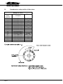
1
Repair instructions MIKRO 22 / 22 R © 02.04 AR025GB Andreas Hettich GmbH & Co. KG • Gartenstraße 100 • D-78532 Tuttlingen • Germany Phone: (07461) 705-0 • Fax: (07461) 705-125 • Internet: www.hettichlab.com • e-mail: [email protected], [email protected] TABLE OF CONTENTS 1. INTRODUCTION...................................................................................................... 6 2. DESCRIPTION OF THE NEW HETTICH CENTRIFUGES ...................................... 7 2.1. Functional structure of the Mikro 22 / 22 R ...................................................... 7 2.2. Control panel (CP) ........................................................................................... 7 2.3. Supply board (SB) A1 ...................................................................................... 8 2.4. Frequency converter (FC) A2 .......................................................................... 8 2.5. Special features ............................................................................................... 9 2.6. Motor / Tacho system ...................................................................................... 9 2.7. Imbalance switch ........................................................................................... 10 2.8. Interlocking .................................................................................................... 10 2.9. Cooling........................................................................................................... 10 2.9.1. Temperature sensor B1 in the centrifuge chamber ................................. 10 2.9.2. Function of the cooling board (CB) A3 .................................................... 10 3. 4. 5. 2.10. Fan................................................................................................................. 10 2.11. Offset calibration............................................................................................ 11 2.12. Protection....................................................................................................... 11 REQUIREMENTS FOR ERROR IDENTIFICATION .............................................. 12 3.1. Correct power supply ..................................................................................... 12 3.2. Functional check ............................................................................................ 12 3.3. Procedure for diagnosing errors .................................................................... 12 ERROR MESSAGES ............................................................................................. 13 4.1. Brief description ............................................................................................. 13 4.2. Description and elimination of errors.............................................................. 15 FACTORY SETTING ............................................................................................. 23 5.1. Control panel ................................................................................................. 23 5.2. Procedure for initialisation.............................................................................. 23 5.3. Imbalance Mode ............................................................................................ 24 5.4. OFFSET alignment ........................................................................................ 24 5.4.1. OFFSET value ........................................................................................ 25 5.4.2. Procedure for performing an OFFSET alignment.................................... 25 5.4.3. Note for temperature sensor in centrifuge chamber ................................ 25 2/51 6. 7. FUNCTION RETRIEVALS / SETTINGS................................................................. 26 6.1. Acoustic signal ............................................................................................... 26 6.2. Hours of operation.......................................................................................... 26 6.3. Slippage of the drive ...................................................................................... 27 6.4. Setting display contrast on control panel........................................................ 27 FUNCTIONAL CHECK........................................................................................... 28 7.1. 8. 9. Functional check at factory............................................................................. 28 FUNCTIONAL TEST .............................................................................................. 30 8.1. Checking the proper working order ................................................................ 30 8.2. Proper working order after repairs.................................................................. 30 ASSEMBLING AND DISASSEMBLING COMPONENTS...................................... 30 9.1. Speed sensor B3 (speedometer) ................................................................... 33 9.2. Motor M1 / Vibration damper.......................................................................... 33 9.3. FC (frequency converter) ............................................................................... 33 9.4. SB (supply board) A1 ..................................................................................... 33 9.5. CB A3 (cooling board) only MIKRO 22 R ....................................................... 33 9.6. CP (control panel) A4..................................................................................... 34 9.7. EPROM at CP ................................................................................................ 34 9.8. CC (control cables) ........................................................................................ 34 9.9. LL (Y1) (lid locking) ........................................................................................ 34 9.10. BR R1 (brake resistor) ................................................................................... 34 9.11. Radio interference suppression filter Z1......................................................... 34 9.12. Mains choke coil (L1) ..................................................................................... 34 9.12.1. Assembly and disassembly ..................................................................... 34 9.12.2. Short the mains choke coil ...................................................................... 35 9.13. Mains switch Q1............................................................................................. 35 9.14. Appliance plug B4, overvoltage protection F1 ................................................ 36 9.15. Imbalance switch S1 ...................................................................................... 36 9.16. Temperature sensor B1 in centrifuge chamber .............................................. 36 9.17. Temperature sensor B2 at condenser............................................................ 36 9.18. Fan M3 ........................................................................................................... 36 9.19. Compressor M2.............................................................................................. 36 9.20. Lid spring........................................................................................................ 37 9.21. Hinge block .................................................................................................... 37 3/51 10. SPEEDOMETER-CODE-POSITION OF THE ROTORS .................................... 38 11. CIRCUIT DIAGRAMS......................................................................................... 40 11.1. Mains supply with supply board (SB) 230 V................................................... 40 11.2. Mains supply with supply board (SB) 115 V................................................... 41 11.3. Circuit diagram supply board (SB) ................................................................. 42 11.4. Connecting diagram and component layout supply board (SB) ..................... 43 11.5. Signals at control cable (between CP-SB) ..................................................... 45 11.6. Block diagram control panel (CP) .................................................................. 46 11.7. Connecting diagram Control board (CP)........................................................ 47 11.8. Block diagram and signals at frequency converter (FC) ................................ 48 11.9. Connecting diagram frequency converter (FC) .............................................. 51 11.10. Circuit diagram cooling board ..................................................................... 52 11.11. Connecting diagram and component layout cooling board......................... 54 12. 4/51 TECHNICAL SPECIFICATIONS ........................................................................ 57 Abbreviations CP FC SB CB CC LL BC BR MR EC ES ER M ECR Control panel Frequency converter Supply board Cooling board Control cable Lid locking Braking chopper Brake resistor Mains reset Mains switch OFF - ON Error cause Error consequence Error remedy Measurement Error-code reset 5/51 1. • Introduction This repair instruction is only intended for specialized staff authorized by HETTICH. Interventions and modifications at centrifuges, which have been conducted by persons not authorized by HETTICH, are at their own risk and entail the loss off all guarantee and liability claims. In such an event any guarantee claim or liability claim against the HETTICH expire. • The aim of these repair instructions is to enable any errors to be located and eliminated quickly. There should be no interventions at, or replacement of components on the individual electronics boards. Experience shows that if an intervention is not performed in accordance with regulations, or if a component is installed whose specification is not identical to that of the original component, then the error (defect) which has occurred will be compounded by further damage. In such an event any guarantee claim or liability claim against the HETTICH ceases to exist. Any electronics boards which are not repaired in accordance with the regulations cannot be acknowledged as being replacement spare parts. • • • Information about the operation of the centrifuge please see operating instructions. We reserve all rights for these technical documents. Technical alterations reserved. 6/51 2. Description of the new Hettich centrifuges 2.1. Functional structure of the Mikro 22 / 22 R These microprocessor-controlled centrifuges are comprised of the following electrical components: • Control panel (CP), microprocessor-controlled • Supply board (SB) • Frequency converter (FC, motor control), microprocessor-controlled • Motor with speed sensor (speedometer) • Braking chopper (BC) with brake resistor (BR) • Lid locking (LL) • Cooling board (CB), only Mikro 22 R 2.2. Control panel (CP) The CP is the ”brain” or ”master” of the centrifuge. Via a serial data bus system, the MASTER controls its SLAVE, the component: − frequency converter (FC) The individual tasks of the CP are: • Management of operator inputs and control of LCD display • Storage of 3 run programs • Control of components: − FC via the enabling circuit and via the serial interface − cooling and fan • Evaluation of the speed sensor (speedometer) • Evaluation of the imbalance switch. • Evaluation of the FC fault alarm circuit • Evaluation of the LL open/closed signalling circuit • Control of the relay for the LL solenoid at rotor standstill • Temperature measurement and sensor evaluation of the temperature sensor in centrifuge chamber (only refrigerated centrifuge). • Routine for input, storage and transfer of temperature offset values • Format of the serial interface: 5 Volt interface with 3 conductors (16-pole control cable, pole 6, 8 and 11) • The CP is powered from the SB via the control cable: + 10...15 Volt pole 1,2 GND pole 15,16 CP : control panel, FC : frequency converter, SB : supply board, CB : cooling board, CC : control cable, LL : lid locking, BC : braking chopper, BR : brake resistor, MR : mains reset, EC : error cause, ES : error consequence, ER : error remedy, M : measurements, ECR : error-code reset 7/51 2.3. Supply board (SB) A1 The SB performs the following individual functions: • 12 V DC and 5 V DC supply for the SB. • 12 V DC supply for the CP. • 12 V DC supply for the CB (only Mikro 22 R). • Plugging station X5 for mains power supply, LL magnet and transmission of the signalling circuit for LL switch (open/closed over opto-coupler to the CP). • Power supply for speed sensor (speedometer). • Plugging station X4 for speed sensor cable and transmission to the CP and FC. • Control of the relay for the LL solenoid at rotor standstill • Plugging station X3 for the imbalance switch and direct transmission of the imbalance signal to the CP. • The 5 Volt interface with 3 conductors is converted to an RS 485 interface with 2 conductors: Interface to FC: RS 485-interface via 2 conductors • Transfer of primary enabling (=Hardware STOP) CP ⇒ FC • Transfer of fault circuit (=FC-ERROR) FC ⇒ CP 2.4. Frequency converter (FC) A2 The FC performs the following individual functions: • Generation of the motor power supply (3-phase AC current of variable frequency and voltage) Mode of operation: The mains supply is rectified, smoothed and chopped in three bridge elements to give a pulse-duration modulated supply. • Monitoring of the motor current • Evaluation of the overtemperature switch in the motor (only version 115V, AC) • Slave behaviour (handling of interrogations and commands from the CP via the serial interface): RS 485-interface with 2 conductors (10-pole control cable, pole 3 and 5) • Evaluation of the primary enabling (=Hardware STOP) for the FC (10-pole control cable, pole 7) • Evaluation of potential faults and monitoring of the fault circuit (=FC-Error) (10-pole control cable, pole 4) • The electrical power, which resulted from braking, will be conducted to the BR. The braking chopper switches at a voltage: from approximately 390V (230V series) from approximately 200V (115V series) • The BR is protected by an overtemperature switch. At a short circuit on the BC, which is located on the FC, the BR overheats because of high current. The overtemperature switch cuts off the voltage supply from the FC. After cooling down at the BR the voltage supply is switched on again. CP : control panel, FC : frequency converter, SB : supply board, CB : cooling board, CC : control cable, LL : lid locking, BC : braking chopper, BR : brake resistor, MR : mains reset, EC : error cause, ES : error consequence, ER : error remedy, M : measurements, ECR : error-code reset 8/51 • The CP issues the following via the serial interface: − Speed − Starting and braking levels − Control commands START, BRAKE, STOP In standby mode the green LED is on • State display by LED´s: In running mode the green LED is on In fault mode the green LED flashes If the FC processor detects a fault, it shuts down itself automatically and triggers the fault circuit (FC-ERROR). The CP then interrogates the type of fault via the serial interface. 2.5. Special features • Multiprocessor concept: Although one microprocessor will fail, the other one will continue to monitor its assigned area. If the CP fails, the drive will be shut down automatically by the FC when no interrogations have been received via the interface for more than 30 seconds. • Interface concept: Transmission of data is monitored by an extra check sum. • Hardware concept: All switches with a safety relevant function are of the NC-contact type, which means that loose contacts and open-circuit faults can also be detected. 2.6. Motor / Tacho system • The motor is a 3 phase asynchronous motor with 2 pairs of poles. • A speed sensor (speedometer) attached to the motor receives the following from the transmitter attached to the rotor, − rotor code information (see section 10) and − speed data (6 pulses per revolution) • The ACTUAL speed is monitored and controlled via the CP − Double safety: The FC is also programmed that no value of speed in excess of the maximum permitted rotor speed can be selected. The FC monitors the speed and switches off at excess speed with error code “ERROR 84”. • Rotor standstill is monitored via the CP. − The lid can only be opened when the CP has detected standstill. CP : control panel, FC : frequency converter, SB : supply board, CB : cooling board, CC : control cable, LL : lid locking, BC : braking chopper, BR : brake resistor, MR : mains reset, EC : error cause, ES : error consequence, ER : error remedy, M : measurements, ECR : error-code reset 9/51 2.7. Imbalance switch • A switch detects any imbalance. • Imbalance can only be detected in running mode (starting, centrifuging and braking). • If any imbalance is detected, the drive is changed over to braking. 2.8. Interlocking • Opening of the LL is prevented by a latch. The LL can only be opened when the relay on the SB is energized by the CP. This occurs when the rotor is at standstill and mains power is applied. A solenoid is energized and releases the latch. • The centrifuge can only be started when the lid is closed. A microswitch on the LL detects the position of the LL. 2.9. Cooling • Temperature behaviour: − When rotor is at standstill and the lid is locked, the cooling is operating. − When rotor is at standstill and the lid is unlocked, there is no cooling. 2.9.1. Temperature sensor B1 in the centrifuge chamber • This temperature is processed in the CP. • The housing of the temperature sensor B1 also contains an overtemperature switch. In refrigerated centrifuges this switch cuts off the drive at > 60°C. 2.9.2. Function of the cooling board (CB) A3 • Plugging station (X3) for the temperature sensor and the overtemperature switch in the centrifuge chamber. • The voltage of the temperature sensor in the centrifuge chamber plug X4 being transmitted over a 10-pole CC to the CP plug X101. • The signal of the overtemperature switch in the centrifuge chamber plug X4 being onward transmitted over a 10-pole CC to the CP plug X101. • Plugging station (X2) for the overheating protection B2 at the condenser. • Relay circuit for the compressor and the fan. The overheating protection B2 at the condenser is series connected to the relay voltage. • Plugging station (X1) for the compressor and the fan. 2.10. Fan • The fan cools down the refrigerant flowing through the condenser. • The fan is parallel-connected to the compressor. CP : control panel, FC : frequency converter, SB : supply board, CB : cooling board, CC : control cable, LL : lid locking, BC : braking chopper, BR : brake resistor, MR : mains reset, EC : error cause, ES : error consequence, ER : error remedy, M : measurements, ECR : error-code reset 10/51 2.11. Offset calibration • Offset calibration is performed in order to equalize the tolerances of the temperature sensor and the electronics. Perform Offset calibration when replacing: Where/How − the temperature sensor − the CP calibrate the temperature sensor. calibrate temperature sensor and read out the old offset values and put them in the new CP. Read out the old offset values and put them in the new CP. − the CP-EPROM 2.12. Protection Mains power input ⇒ Mains input with overvoltage protection. Mains switch ⇒ Thermal overload protection (fuse). FC ⇒ Electronic protection. Motor ⇒ Overtemperature cutout > 135°C (only 115V version). Cooling ⇒ Overtemperature switch in centrifuge chamber and at condenser. CP : control panel, FC : frequency converter, SB : supply board, CB : cooling board, CC : control cable, LL : lid locking, BC : braking chopper, BR : brake resistor, MR : mains reset, EC : error cause, ES : error consequence, ER : error remedy, M : measurements, ECR : error-code reset 11/51 3. Requirements for error identification 3.1. Correct power supply • All fuses of house installation are intact. Mains voltage is present on the following circuits: • • • • • Cable leading to mains cable Appliance plug Mains switch Radio interference suppression filter Supply board A1 (SB), plug X5, (PIN 1 and PIN 5) 3.2. Functional check • Mains switch is ON. • All LED`s on control panel must light up. • The centrifuge type and the software version number appears in the display. • After about 8 sec. the display switches over to − the most recently used centrifuging data or − the error code. 3.3. Procedure for diagnosing errors • Look for the displayed error code in the chapter 4 "Error messages". • Remedy the error according to the instructions. • Carry out a functional check after every repair and whenever a component is replaced. • The technical data which were determined during the final check can be found in the chapter 7 "Functional check". CP : control panel, FC : frequency converter, SB : supply board, CB : cooling board, CC : control cable, LL : lid locking, BC : braking chopper, BR : brake resistor, MR : mains reset, EC : error cause, ES : error consequence, ER : error remedy, M : measurements, ECR : error-code reset 12/51 4. Error messages 4.1. Brief description • Error messages in: MIKRO 22 MIKRO 22 R Error designation No. Brief description TACHO-ERROR 01 Speedometer pulses break down during rotation 15 TACHO-ERROR 02 No speedometer pulses after start command 15 Imbalance on motor axle 16 IMBALANCE Page CONTROL-ERROR 04 LL error, lid opened without recognizing that motor had stopped 16 N > MAX 05 Excessive speed error, 250 RPM above n-max of rotor 16 ROTORCODE 10 Invalid rotor code 17 Mains interruption 17 MAINS INTERRUPT VERSION-ERROR 12 Error in initialisation 17 N < MIN 13 Speed error, slippage is too great 18 CONTROL-ERROR 21 CP - error: speed 18 CONTROL-ERROR 22 CP - error: I²C bus 18 CONTROL-ERROR 23 CP - error: display memory 18 CONTROL-ERROR 24 CP - error: clock timeout 18 CONTROL-ERROR 25 CP - error: EEPROM 18 CONTROL-ERROR 26 CP - error: driver defective 18 N > ROTOR-MAX --- CP - error: nominal speed is higher than permitted rotor speed or nominal RCF is higher than permitted rotor RCF 18 SER I/O-ERROR 30 No connection between CP and serial interface 18 SER I/O-ERROR 31 No connection between FC and serial interface 18 SER I/O-ERROR 33 Subassembly data incorrectly transmitted 19 SER I/O-ERROR 34 Data incorrectly transmitted between CP and FC 19 SER I/O-ERROR 36 No acknowledgement (NAK) from FC to CP 19 CP : control panel, FC : frequency converter, SB : supply board, CB : cooling board, CC : control cable, LL : lid locking, BC : braking chopper, BR : brake resistor, MR : mains reset, EC : error cause, ES : error consequence, ER : error remedy, M : measurements, ECR : error-code reset 13/51 Error designation No. No cooling (No error displayed) Brief description Page Overtemperature at condenser 19 °C / *-ERROR 52 Overtemperature in centrifuge chamber 20 °C / *-ERROR 53 Temperature sensor in centrifuge chamber is defective 20 FU/CCI-ERROR 60 Faulty release signal to FC 20 FU/CCI-ERROR 61 FC - error: computing section 21 FU/CCI-ERROR 62 FC - error: undervoltage 21 FU/CCI-ERROR 63 FC - error: overcurrent 21 FU/CCI-ERROR 64 FC - error: overvoltage 21 FU/CCI-ERROR 67 FC - error: overtemperature in motor (only 115V) 22 FU/CCI-ERROR 68 FC - error: overtemperature in FC 22 FU/CCI-ERROR 69 FC - error: EEPROM 22 FU/CCI-ERROR 84 FC - error: FC recognizes excess speed 22 FU/CCI-ERROR 85 FC - error: “Watchdog”in FC had Triggered 22 CP : control panel, FC : frequency converter, SB : supply board, CB : cooling board, CC : control cable, LL : lid locking, BC : braking chopper, BR : brake resistor, MR : mains reset, EC : error cause, ES : error consequence, ER : error remedy, M : measurements, ECR : error-code reset 14/51 4.2. Description and elimination of errors TACHO - ERROR 01 EC During centrifugation the speedometer pulses are interrupted. ES The rotor slows down until it stops. After the rotor stops, there is a DC braking for 30 sec. An MR during slowing-down causes a DC braking for 3 min. After the DC braking, the ”open the lid” release takes place. Further cooling to NOMINAL temperature. ER • Speed sensor (speedometer) defective or loose contact on plug. Measure speedometer pulses on plug X4 / SB, (pin 4 - pin 2). • CC to CP, or CC to FC is defective. • SB or CP or FC is defective. M Also see at SB-X4, CP-X1 (PIN 14 and FC-S501 (PIN 8). ECR Open the lid. Turn the rotor by hand and perform an MR while the rotor is turning. TACHO - ERROR 02 EC There are no speedometer pulses on the CP after startup. ES The rotor slows down until it stops. After the rotor stops, there is a DC braking for 30 sec. An MR during slowing-down causes a DC braking for 3 min. After the DC braking, the ”open the lid” release takes place. Further cooling to NOMINAL temperature. ER • • • • M Also see at SB-X4, CP-X1 (PIN 14 and FC-S501 PIN 8). ECR Startup took place without the rotor. Motor not connected. Motor is defective. Speed sensor (speedometer) defective, or loose contact on plug. Measure speedometer pulses on plug X4 / SB, (pin 4 - pin 2). • CC to CP, or CC to FC is defective. • No release signal to FC. • SB or CP or FC is defective. Open the lid. Turn the rotor by hand and perform an MR while the rotor is turning. CP : control panel, FC : frequency converter, SB : supply board, CB : cooling board, CC : control cable, LL : lid locking, BC : braking chopper, BR : brake resistor, MR : mains reset, EC : error cause, ES : error consequence, ER : error remedy, M : measurements, ECR : error-code reset 15/51 IMBALANCE EC Imbalance on motor axle. ES The centrifuge slows down until the “open the lid” release occurs. Further cooling until NOMINAL temperature is reached. ER • • • • • • • • M Also see at SB-X3 and CP-X1 (PIN 12) ECR Weight difference in rotor components. Supporting lugs not lubricated. False IMBALANCE MODE is set (see chapter "Imbalance Mode"). Imbalance switch not connected. Imbalance switch is defective. Loose contact in cable or plug. CC to CP is defective. CP or SB is defective. Perform an MR. CONTROL - ERROR 04 EC LL is open during centrifugation. ES Slowing down until the ”open the lid” release occurs. Further cooling until NOMINAL temperature is reached. ER • • • • M Also see at SB-X5 (PIN 2 and PIN 6) and CP-X1 (PIN 5). ECR LL is defective and can be opened during centrifugation. Loose contact in cable or in plug. CC to CP is defective. CP or SB is defective. Perform an MR. N > MAX 05 EC Excess speed. The speed recognized by the speed sensor (speedometer) is 250 RPM greater than the n-max speed of the rotor. ES The centrifuge slows down until the ”open the lid” release occurs. Further cooling until NOMINAL temperature is reached. ER • • • • • ECR Insulation of speed sensor (speedometer) cable is defective. Loose contact on speed sensor (speedometer) cable. Speed sensor (speedometer) is defective. CC to CP is defective. CP or FC or SB is defective. Perform an MR. CP : control panel, FC : frequency converter, SB : supply board, CB : cooling board, CC : control cable, LL : lid locking, BC : braking chopper, BR : brake resistor, MR : mains reset, EC : error cause, ES : error consequence, ER : error remedy, M : measurements, ECR : error-code reset 16/51 ROTORCODE 10 EC An invalid rotor code was read during startup. ES The centrifuge slows down until the ”open the lid” release occurs. Further cooling until NOMINAL temperature is reached. ER • • • • M ECR Magnetic coding on rotor is defective. Speedometer system is defective. Loose contact on speed sensor (speedometer) plug The rotation of the rotor (direction) is incorrect. See at section 10. Open the lid or perform an MR. MAINS INTERRUPT EC Interruption of mains supply during centrifugation. ES The centrifuge slows down until the ”open the lid” release occurs. − Switching on at the mains during centrifugation causes slowing-down until the ”open the lid” release occurs. − Switching on at the mains when the rotor has stopped brings about the ”open the lid” release. ER • Power supply has failed. • Loose contact in electrical connections. • CC to CP is defective. ECR Open the lid and press the . key. This error cannot be reset by an MR VERSION - ERROR 12 EC Differences in the initialisation from CP (EPROM) or FC. ES No further user operation is possible. ER • An incorrect EPROM has been plugged into CP. M Also see initialisation section 5.2. ECR Perform an MR. CP : control panel, FC : frequency converter, SB : supply board, CB : cooling board, CC : control cable, LL : lid locking, BC : braking chopper, BR : brake resistor, MR : mains reset, EC : error cause, ES : error consequence, ER : error remedy, M : measurements, ECR : error-code reset 17/51 N < MIN 13 EC Insufficient speed; the slippage of the motor is too great. The centrifuge regulation can adjust the speed by 5% max. (the limit of adjustment). The error is indicated if the ACTUAL speed is lower than the NOMINAL speed minus 5%. ES The centrifuge slows down until the ”open the lid” release occurs. Further cooling until NOMINAL temperature is reached ER • • • • ECR Motor is labouring (damage to bearings). Motor has a short-circuited coil (coil is defective). Loose contact in the electrical connections. FC is defective. Release signal to FC was interrupted during centrifugation. Open the LL. Perform an MR. CONTROL - ERROR 21 - 26 EC Internal error in CP. ES The centrifuge slows down until the ”open the lid” release occurs. ER • CP is defective. ECR Perform an MR. N > ROTOR-MAX EC Error in the entered program ES Further operation is not possible. ER SET speed or SET RCF is higher than the permissible rotor speed or permissible rotor RCF. ECR Carry out a MAINS RESET or open the lid. Reduce the speed or RCF in the entered program to the permissible rotor speed or permissible rotor RCF. SER I/O - ERROR 30 and ERROR 31 EC CP has no connection to the component FC via serial interface. ES The centrifuge slows down until the ”open the lid” release occurs. ER • CC to FC is defective. • There is no voltage on FC. • F2 overtemperature switch on brake resistor has opened or is not connected. • CP or FC is defective. • Cable on plug S102 is not or wrong plugged ECR Perform an MR. CP : control panel, FC : frequency converter, SB : supply board, CB : cooling board, CC : control cable, LL : lid locking, BC : braking chopper, BR : brake resistor, MR : mains reset, EC : error cause, ES : error consequence, ER : error remedy, M : measurements, ECR : error-code reset 18/51 SER I/O - ERROR 33 EC CP is not receiving correct data from FC. ES The centrifuge slows down until the ”open the lid” release occurs. ER • CC to FC is defective. • CP or FC is defective. ECR Perform an MR. SER I/O - ERROR 34 EC CP is not receiving correct data from FC. ES The centrifuge slows down until the ”open the lid” release occurs. Further cooling until NOMINAL temperature is reached. ER • CC to FC is defective. • CP or FC is defective. ECR Perform an MR. SER I/O - ERROR 36 EC FC sends signal NAK to the CP after receiving an unknown command. NAK (not acknowledged). ES The centrifuge slows down until the ”open the lid” release occurs. Further cooling until NOMINAL temperature is reached. ER • CC to FC is defective. • FC is defective. • CP is defective. ECR Perform an MR. NO COOLING EC ES ER M ECR No cooling in centrifuge chamber. Overtemperature at condenser, temperature > 60°C. Cooling switches off. Continuance of centrifugation until temperature switch in the centrifuge chamber triggers and “ERROR 52” appears. The centrifuge slows down until the “open the lid” release occurs. • Condenser soiled. • Loose contact in plug. • SB is defective. • Fan is defective. • Sensor cable B2 is defective. Also see at CB-X2. Perform an MR. CP : control panel, FC : frequency converter, SB : supply board, CB : cooling board, CC : control cable, LL : lid locking, BC : braking chopper, BR : brake resistor, MR : mains reset, EC : error cause, ES : error consequence, ER : error remedy, M : measurements, ECR : error-code reset 19/51 °C / * - ERROR 52 EC ES ER M ECR Overtemperature in centrifuge chamber. The centrifuge slows down until the ”open the lid” release occurs. • Sensor cable B1 is defective. • Loose contact in plug. • CP is defective. • CB is defective. Also see CB-X3 (PIN 1 and PIN 2) and CP-X101 (PIN 4). Perform an MR. °C / * - ERROR 53 EC Temperature sensor in centrifuge chamber has a short circuit or a discontinuity. ES The centrifuge slows down until the ”open the lid” release occurs. Cooling switches off. • Temperature sensor is defective. • Sensor cable B1 is defective. • Loose contact in plug. • CP is defective. • CB is defective. Also see at CB X3 (PIN 5 and PIN 4) and CP-X101 (PIN 8). ER M ECR Perform an MR. FU / CCI - ERROR 60 EC ES ER The release signal was not correctly transmitted to FC. The evaluation of the release signal only occurs once after MR. No further user operation is possible. • CC to FC is defective. • CC to CP is defective. • SB is defective. M Also see at CP-X1 (PIN 4) and FC-S501 (PIN 7). CP : control panel, FC : frequency converter, SB : supply board, CB : cooling board, CC : control cable, LL : lid locking, BC : braking chopper, BR : brake resistor, MR : mains reset, EC : error cause, ES : error consequence, ER : error remedy, M : measurements, ECR : error-code reset 20/51 General Notice for FU / CCI - ERROR 61 to FU / CCI - ERROR 69 • • • • FC switches independently. The rotor freewheels, coasting. No further user operation is possible. Cooling continues until nominal value is attained. ECR • • Mains switch is OFF. Switch mains switch to ON after 1 min. M Also see at FC-S501 (PIN 4) and CP-X1 (PIN 13). ES FU / CCI - ERROR 61 EC Error in computing section. ER • CC is defective. • FC is defective. FU / CCI - ERROR 62 EC Undervoltage. Mains voltage less than 20% as nominal voltage. ER • Supply voltage too low, see chapter "Short the mains choke coil". • CC is defective. • FC is defective. M Also see at FC, UDC. FU / CCI - ERROR 63 EC Overcurrent. ER • • • • Short circuit in motor. Motor impedance is too low. CC is defective. FC is defective. FU / CCI - ERROR 64 EC Voltage in intermediate circuit: > 410 V DC at 230 V > 205 V DC at 115 V This error normally only occurs when the drive is being braked. ER • BR is defective. • CC is defective. • FC is defective. M Also see FC, UDC. CP : control panel, FC : frequency converter, SB : supply board, CB : cooling board, CC : control cable, LL : lid locking, BC : braking chopper, BR : brake resistor, MR : mains reset, EC : error cause, ES : error consequence, ER : error remedy, M : measurements, ECR : error-code reset 21/51 FU / CCI - ERROR 67 EC Only centrifuges with 115 V. Overtemperature in the motor. The cable “overtemperature” in the motor has high impedance. ER • Overtemperature switch opens because of overtemperature in the motor • CC is defective. • FC is defective. • Motor is defective M • Also see at FC S2. FU / CCI - ERROR 68 EC Overtemperature in FC. ER • Insufficient heat abduction from FC to centrifuge housing. There is no, or not enough, heat-conducting paste between FC and housing. • Full-load operation and an ambient temperature > 45°C. • CC is defective. • FC is defective. FU / CCI - ERROR 69 EC EEPROM in FC is defective. ER • CC is defective. • FC is defective FU / CCI - ERROR 84 EC ER M FC recognizes excess speed. • During rotation the speedometer pulses (6 per revolution) are controlled by the FC. • The FC switches the centrifuge off, when the maximum speed is exceeded more than 500 rpm. • CCis defective. • FC is defective. Also see at SB-X4 and FC-S501 (PIN 8). FU / CCI - ERROR 85 EC ER “Watchdog” in FC Discrepancy in program procedure • CCis defective. • FC is defective. CP : control panel, FC : frequency converter, SB : supply board, CB : cooling board, CC : control cable, LL : lid locking, BC : braking chopper, BR : brake resistor, MR : mains reset, EC : error cause, ES : error consequence, ER : error remedy, M : measurements, ECR : error-code reset 22/51 5. Factory setting 5.1. Control panel (Only in a cooled centrifuge) PROG Control field Display field T / °C >RCF< RPM t / min:s IMPULS START STOP PROG RCF Entry field . The EPROM of the CP must, in all circumstances, correspond to the machine version and the cooling version. 5.2. Procedure for initialisation An initialization must be carried out: • after replacing the FC. The frequency converter must be adjusted to the centrifuge. Requirement: 1. Rotor has stopped. 2. LL is open. 3. Mains switch is OFF. 4. Plug on coding strip X3 on the CP has a jumper in slot 3 and in slot 4 (initialisation position). • Mains switch is ON • Press • Press the key key → Display: → Display: → Display: INIT - MODE VERS 12 °C / * 01 ↑ ↑ machine version Cooling version (01 = with cooling, 00 = without cooling) IMBALANCE MODE 2 • Press the or key to set IMBALANCE MODE 1 or IMBALANCE MODE 2. Now START key to save this setting. Information about IMBALANCE MODE see press the chapter "Imbalance Mode". • Press key → Display: PARAM - INIT 0000 ↑ ↑ machine version Number of initialisations CP : control panel, FC : frequency converter, SB : supply board, CB : cooling board, CC : control cable, LL : lid locking, BC : braking chopper, BR : brake resistor, MR : mains reset, EC : error cause, ES : error consequence, ER : error remedy, M : measurements, ECR : error-code reset 23/51 • Press . → key Display: and then: *** OK *** PARAM - INIT C001 ↑ ↑ machine version Number of initialisations • Mains switch is OFF • Remove both jumpers from slot 3 and slot 4 on coding strip X3 on the CP. Put a jumper on slot zero at the plug on coding strip X3 on the CP. (Service position, “Watchdog”) An initialisation is always necessary after a replacement of the FC. 5.3. Imbalance Mode From programme version 3.00 it is necessary to set the imbalance mode during the initialization. Depending on the SB version IMBALANCE MODE 1 or IMBALANCE MODE 2 must be selected. If the incorrect imbalance mode is selected, the display shows error "IMBALANCE" permanently ! 5.4. OFFSET alignment An OFFSET alignment is performed to align the temperature sensor and the CP electronics with one another. An alignment must be performed in any event: − 1. Replacement of the temperature sensor at the centrifuge chamber. − 2. Replacement of the CP or the EPROM at the CP. The OFFSET alignment for the temperature sensor is carried out in the CP. To carry out an offset compensation, measure the temperature directly on the temperature sensor with a temperature measuring device. Then enter the measured value in the display and save it. Each correction must be confirmed by the Requirements: 1. 2. 3. 4. . key. Rotor has stopped. LL is open. Mains switch is OFF. Plug on coding strip X3 at the CP the jumper from slot 0 to slot 3 (OFFSET position). CP : control panel, FC : frequency converter, SB : supply board, CB : cooling board, CC : control cable, LL : lid locking, BC : braking chopper, BR : brake resistor, MR : mains reset, EC : error cause, ES : error consequence, ER : error remedy, M : measurements, ECR : error-code reset 24/51 5.4.1. OFFSET value The OFFSET value is the difference between the actual temperature and the sensor temperature. Example: 5.4.2. Actual temperature - Sensor temperature 25.5 °C 27.0 °C = OFFSET value = -1.5 °C Procedure for performing an OFFSET alignment 1. Mains switch is ON 2. Press key → Display: * OFFSET - MODE * → Display: T1: 27,0 °C → ↑ 25,5 °C ↑ Sensor temperature Actual temperature • The sensor temperature measured is to be adjusted with the make it agree with the actual temperature. 3. Press the key → Display: keys to *** OK *** • If the temperature settings are not confirmed by pressing the old settings will be maintained. 4. Mains switch is OFF. 5. Remove jumper from slot 3 on coding strip X3 on the CP. . key, the Put the jumper on slot zero at the plug on coding strip X3 on the CP (Service position, “Watchdog”). 5.4.3. Note for temperature sensor in centrifuge chamber If the temperature in the sample deviates from the nominal value (Display), the offset alignment can be altered as follows: − Actual temperature is lower than nominal temperature: Set the offset temperature of T1 lower by the amount of the deviation (the corrected value is lower). − Actual temperature is higher than nominal temperature: Set the offset temperature of T1 higher by the amount of the deviation. CP : control panel, FC : frequency converter, SB : supply board, CB : cooling board, CC : control cable, LL : lid locking, BC : braking chopper, BR : brake resistor, MR : mains reset, EC : error cause, ES : error consequence, ER : error remedy, M : measurements, ECR : error-code reset 25/51 6. Function retrievals / settings Requirements: 1. Rotor is stopped. 2. Mains switch is ON Keep play: key pressed down until (after about 8 sec.) the following appears in the dis1. SOUND / BELL ON1 or OFF (acoustic signal) Press key. Every time the key is pressed, the display alters as follows: Hours of operation 2. CONTROL XXXXX h Machine version, cooling version 3. VERS XX °C / * XX FC type 4. FU / CCI - 1000 FC software 5. FU / CCI - S. 00.XX If nothing more is keyed in for 8 sec., the CP switches over to normal mode. Only Nos. 1. and 2. of the function retrievals listed here can be altered. 6.1. Acoustic signal After in the display appears: • SOUND / BELL ON1 or SOUND / BELL OFF the acoustic signal can be deactivated or activated after standstill using the keys. ON1 Every 30 sec. there is an acoustic acknowledgement that the rotor has stopped. The acknowledgement can be silenced by pressing a key or opening the lid. OFF The fact that the rotor has stopped is not acknowledged acoustically. The setting of the acoustic signal must be confirmed by pressing the key. In the event of an error, the acoustic signal sounds every 2 sec. until a key is pressed or the lid is opened. . 6.2. Hours of operation After the CONTROL XXXXX h appears, the hours of operation can be seen and, after keys. being selected by pressing the RCF key, can be altered using the The key sets the hours-of-operation indicator to 0. The key increases the hours-of-operation display by 1. To make the number of hours increase quickly, keep the key pressed down. The setting of the hours of operation must be confirmed by pressing the key. . CP : control panel, FC : frequency converter, SB : supply board, CB : cooling board, CC : control cable, LL : lid locking, BC : braking chopper, BR : brake resistor, MR : mains reset, EC : error cause, ES : error consequence, ER : error remedy, M : measurements, ECR : error-code reset 26/51 6.3. Slippage of the drive Requirement: The centrifuge is running at its rated speed. Permissible slippage: < 5% of the rated speed. Keep the display: key pressed down until (after about 8 sec.) the following appears in the XXXX ________ ↑ Actual speed in RPM When the 6.4. ∧ XXXX ________ ↑ Rotary frequency in RPM key is pressed again, the CP switches to normal mode. Setting display contrast on control panel The display contrast has been preset at the factory, but can be readjusted. Requirements: The control panel is at room temperature (20 ... 25°C). The contrast must be adjusted so that the background pixels are not visible. Adjustment: Using a screwdriver, adjust the contrast on the trimming potentiometer on the rear side of the control section (see diagram). Rear side of control panel: CP : control panel, FC : frequency converter, SB : supply board, CB : cooling board, CC : control cable, LL : lid locking, BC : braking chopper, BR : brake resistor, MR : mains reset, EC : error cause, ES : error consequence, ER : error remedy, M : measurements, ECR : error-code reset 27/51 7. Functional check 7.1. Functional check at factory Following accessories are required to perform the functional check: • Testing rotor • Two reaction receptacles filled with water Table 7 lists measured values, and, ranges of measured values, which have been laid down for these accessories. In the final check, the functional efficiency of each centrifuge is verified, with the measured values and ranges of measured values being taken into account. Table 7 Measurements carried out on the centrifuges at the factory with testing rotor load: two reaction receptacles reaction receptacles filled with MIKRO 22 MIKRO 22 R 1153 1.5 ml Water Measuring instruments used in final check Temperature measuring instrument THERM 2250-1 X Moving-iron current measuring instrument X Moving-coil current measuring instrument X Rated speed Slippage nmax at nmax Starting current up to nmax RPM RPM 14000 100 – 400 A 7.0 - 7.7 A Rated current up to nmax A 2.0 - 2.7 A Total current with cooling A ≤ 3.0 A Starting time Rundown time Starting time Rundown time Stage 9 up to nmax Stage 9 from nmax Stage 5 up to RPM 4000 Stage 5 from RPM 4000 Imbalance Run through at Switch off at sec sec sec sec 9 – 13 14 – 18 20 – 25 23 – 28 g g ≤2 ≥7 CP : control panel, FC : frequency converter, SB : supply board, CB : cooling board, CC : control cable, LL : lid locking, BC : braking chopper, BR : brake resistor, MR : mains reset, EC : error cause, ES : error consequence, ER : error remedy, M : measurements, ECR : error-code reset 28/51 Temperature measured at room temperature RT Sample temperature after 1 h running time ≤26 °C RT + 17 K Sample temperature in cooled centrifuges after 1 h running time 1st run 2nd run 3rd run 4°C 20°C 37°C 14000 RPM nmax nmax +2 °C to +6 °C +18 °C – 22 °C +35 °C– 39 °C Machine temperatures after 2nd run Motor: Unscrew motor covering and measure at stator lamination bundle RT + 70 K A bearing: Measure ball bearing temperature at inner ring RT + 70 K FC: Measure at FC fastening brackets RT + 20 K CP : control panel, FC : frequency converter, SB : supply board, CB : cooling board, CC : control cable, LL : lid locking, BC : braking chopper, BR : brake resistor, MR : mains reset, EC : error cause, ES : error consequence, ER : error remedy, M : measurements, ECR : error-code reset 29/51 8. Functional test 8.1. Checking the proper working order By measuring and comparing the data listed under Table 7, it can be determined if a centrifuge is in proper working order. A precondition for this is that the necessary components stated under Table 7 are used for the measurements. If the measurements are carried out using other components, the numerical values from the ”Rotor and accessories” chapter of the operating instructions for the particular centrifuge must be employed. If the measured values obtained for: • • • the speed, the starting and rundown times the temperatures in cooled centrifuges, are identical to the numerical values in Table 7, or to those in the ”Rotor and accessories” section of the operating instructions, then the centrifuge is in proper order. 8.2. Proper working order after repairs See section headed ”Checking the proper working order”. The following values must be checked in addition: • Insulation resistance • Protective conductor resistance • Leakage current > 2 MΩ < 0,2 Ω < 3,5 mA * * limit according to EN 61010 A laboratory centrifuge do not belong to those medical appliances which may be tested according to the regulation IEC 601 or corresponding national medical electronic standards. Laboratory centrifuges are classified as laboratory equipment. The regulations applying to laboratory equipment are IEC 1010 or European standard EN 61010. 9. Assembling and disassembling components Before assembling or disassembling components, the working processes in Table 9-B for MIKRO 22 and MIKRO 22 R must first be carried out to reach the components and make a note of the plug numbers. The components are assembled in reverse order ! The further procedure is described on the following pages. CP : control panel, FC : frequency converter, SB : supply board, CB : cooling board, CC : control cable, LL : lid locking, BC : braking chopper, BR : brake resistor, MR : mains reset, EC : error cause, ES : error consequence, ER : error remedy, M : measurements, ECR : error-code reset 30/51 In Table 9-A the components are ordered in the following sequence: Column 1: Column 2: Column 3: Column 4: Column 5: Column 6: Abbreviation Components Abbreviations in the circuit diagrams Plug connections Connections at the electronic-panels Described in capture. Table 9-A 1 A B C D E F G H I J K L M N O P Q R T U V W X Y 2 Speed sensor (speedometer) Motor Vibration damper FC (frequency converter) EPROM (on FC) SB (supply board) CB (cooling board) CP (control panel) EPROM (on CP) Mains choke coil CC (control cables) - 16 conductors - 10 conductors - 10 conductors LL (lid locking) BR (brake resistor) Radio interference suppression filter Mains switch ON / OFF Appliance plug Overvoltage protection Imbalance switch Temperature sensor (centrifuge chamber) Temperature sensor (condenser) Fan (compressor) Compressor Lid spring Hinge block 3 B3 M1 4 X4 S101 5 A1 A2 A2 A2 A1 A3 A4 A4 - Y1 R1 Z1 Q1 B4 F1 S1 B1 B2 M3 M2 A4-A1 A1-A2 A4-A3 X5 P10-P1 X5-Q1 Z1-F1 F1 B4-Q1 X3 X3 X2 X1 X1 A1 A2 A1 A1 A3 A3 A3 A3 6 9.1 9.2 9.2 9.3 9.3 9.4 9.5 9.6 9.7 9.12 9.8 9.9 9.10 9.11 9.13 9.14 9.14 9.15 9.16 9.17 9.18 9.19 9.20 9.21 CP : control panel, FC : frequency converter, SB : supply board, CB : cooling board, CC : control cable, LL : lid locking, BC : braking chopper, BR : brake resistor, MR : mains reset, EC : error cause, ES : error consequence, ER : error remedy, M : measurements, ECR : error-code reset 31/51 Table 9-B Working processes 1. Open lid 2. Set mains switch to OFF 3. Disconnect centrifuge from mains voltage 4. Disassemble rotor 5. Remove motor covering in centrifuge chamber 6. Take rubber sleeve under motor covering out 7. Detach front screen 8. Pull of the control cable from the CP 9. Remove front screen 10. Detach rear covering Example: A B C D E F GH I J K L MN OP QR S T U V W X X X X X X X X X X X X X X X X X X X X X X X X X X X X X X X X Y X X X X X X X X X X X X X X X X X X X X X X X X X X X X X X X X X X X X X X X X X X X X X X X X X X X X X X X X X X X X X X X X X X X X X X X X X X X X X X X X X X X X X X X X X X X X X X X X X X X X X X X X X X X X X X X Disassembling appliance plug 1. Definite the abbreviation of the appliance plug in Table 9-A, column 1. Appliance plug = P 2. See Table 9-B column P and carry out the working processes in numeric order. 3. Definite in Table 9-A the corresponding abbreviation, for the example line P and pick out in column 6 the especially capture (9.13), where the disassembly is described. CP : control panel, FC : frequency converter, SB : supply board, CB : cooling board, CC : control cable, LL : lid locking, BC : braking chopper, BR : brake resistor, MR : mains reset, EC : error cause, ES : error consequence, ER : error remedy, M : measurements, ECR : error-code reset 32/51 9.1. Speed sensor B3 (speedometer) • Unscrew speed sensor (speedometer) from upper end plate of motor. • Unplug plug number X4 from Supply board A1. • Replace speed sensor (speedometer). 9.2. Motor M1 / Vibration damper • Unscrew speed sensor (speedometer) from upper end plate of motor, and place it in centrifuge chamber. • Pull out the 3 cables from plug S101 at the FC (BU/BN/BR). • Use a socket spanner to loosen and remove the three fastening nuts on lower end plate of motor. • Lift motor upwards out of centrifuge. Unplug the earth lead. • Before motor is installed, the three vibration dampers must be checked for possible wear or cracks, and if necessary replaced. • Replace the motor. • Care must be taken of the anti-twist device when the vibration dampers are being installed. 9.3. • • • • • FC (frequency converter) Pull all plugs out of FC. Unscrew the four fastening screws of FC. Unscrew the screws on the connecting clips and pull the cables out. Replace FC Before installation, it must be noted that there is a heat-conducting paste between FC and centrifuge housing floor. Heat conducting from FC to centrifuge housing floor must be ensured. 9.4. SB (supply board) A1 • All plugs on the SB must be pulled out. • Unscrew the four screws, and take SB out of centrifuge. • Replace SB 9.5. • • • • CB A3 (cooling board) only MIKRO 22 R All plugs on the CB must be pulled out. Unplug the two cables (RD and BK) at the SB. Unscrew the four fastening screws at the CB. Replace the CB. CP : control panel, FC : frequency converter, SB : supply board, CB : cooling board, CC : control cable, LL : lid locking, BC : braking chopper, BR : brake resistor, MR : mains reset, EC : error cause, ES : error consequence, ER : error remedy, M : measurements, ECR : error-code reset 33/51 9.6. CP (control panel) A4 • Detach the two holding frames at the CP. • Lift out the CP on the opening at the front screen. • Replace the CP. 9.7. EPROM at CP • Pull the EPROM carefully out of IC-socket. • Pay attention to the polarity of the EPROM when installing. • Do not bend the IC-pins. Before touching the EPROM ensure that your own static electricity is discharged. • Replace the EPROM. 9.8. • • Unplug the corresponding control cable from the boards. Replace the control cable. 9.9. • • • • LL (Y1) (lid locking) Remove the front panel. Unplug all cable from the lid lock. Loosen the to fastening screws on the to of the housing. Exchange the lid lock. 9.10. • • • • CC (control cables) BR R1 (brake resistor) From below loosen the two fastening screws of the BR at the floor. Unplug the cables at the BR and the FC. Loosen cable at overtemperature switch on the BR (clip S102, position U1). Replace BR. 9.11. Radio interference suppression filter Z1 • Unscrew the fastening screws of the radio interference suppression filter. • Remove the plugs from the radio interference suppression filter. • Replace the radio interference suppression filter. 9.12. Mains choke coil (L1) 9.12.1. Assembly and disassembly • Pull both plugs from the mains choke coil. • Undo the fastening screws of the mains choke coil. • Replace the mains choke coil. CP : control panel, FC : frequency converter, SB : supply board, CB : cooling board, CC : control cable, LL : lid locking, BC : braking chopper, BR : brake resistor, MR : mains reset, EC : error cause, ES : error consequence, ER : error remedy, M : measurements, ECR : error-code reset 34/51 9.12.2. Short the mains choke coil In countries, in which the European standard EN 61000-3-2 applies it is not allowed to short the mains choke coil. The mains choke coil reduces the mains input current below the limit values stated in the above mentioned European standard. If the centrifuge is run with undervoltage, that is mains frequency 50 Hz with a voltage < 205 V or mains frequency 60 Hz with a voltage < 210 V the voltage drop of the mains choke coil can cause the error FU / CCI - ERROR 62. The short of the mains choke coil will increase the supply voltage of the frequency converter. • Pull both plugs (A) and remove the cable, see Figure 1. • Pull the plug (B) from the mains choke coil (see Figure 1) and plug it onto the free connector from the radio interference suppression filter (C), see Figure 2. B A C Figure 1 9.13. Figure 2 Mains switch Q1 • Press mains switch out of lower part of housing. • Remove all plugs at mains switch. • Replace mains switch. CP : control panel, FC : frequency converter, SB : supply board, CB : cooling board, CC : control cable, LL : lid locking, BC : braking chopper, BR : brake resistor, MR : mains reset, EC : error cause, ES : error consequence, ER : error remedy, M : measurements, ECR : error-code reset 35/51 9.14. • • • • • • • Appliance plug B4, overvoltage protection F1 Remove mains switch, see chapter 9.13. Unscrew the two fastening screws at the appliance plug. Pull the appliance plug out of the opening. Remove the overvoltage protection from the appliance plug. Replace appliance plug. Unplug the cables at the overvoltage protection. Replace overvoltage protection. 9.15. Imbalance switch S1 • Remove plug from position X3 at the SB. • From below loosen the two fastening screws of the imbalance switch. • Loosen the fastening nuts from the motor. Lift up the motor and pick up the imbalance switch through the opening at the centrifuge chamber. • Replace imbalance switch. 9.16. Temperature sensor B1 in centrifuge chamber • Remove plug from position X3 at the CB. • Remove the lock with appropiate tools at the front of the plug. Then press out the four bushes. • Press out the temperature sensor in the centrifuge chamber. • Replace temperature sensor. 9.17. • • • • • Remove upper housing part with lid (four screws). Lift up the upper housing part and the lid. Unscrew temperature sensor at the mounting (one screw). Unplug plug from position X2 at the CB. Replace temperature sensor. 9.18. • • • • • Fan M3 Remove upper housing part with lid (4 screws). Lift up the upper housing part and the lid. Detach fan. Unplug the two plugs at the fan. Replace fan. 9.19. • • • • • Temperature sensor B2 at condenser Compressor M2 Remove upper housing part with lid (4 screws). Lift up the upper housing part and the lid. Loosen the four hex nuts at the compressor below. Loosen the cable at compressor. Replace compressor. CP : control panel, FC : frequency converter, SB : supply board, CB : cooling board, CC : control cable, LL : lid locking, BC : braking chopper, BR : brake resistor, MR : mains reset, EC : error cause, ES : error consequence, ER : error remedy, M : measurements, ECR : error-code reset 36/51 9.20. • • • • Open the lid. Loosen the fastening screws at the inner side of the lid. Pull up the external lid part out of the guideway. Replace defective component. 9.21. • • • • • • • Lid spring Hinge block Remove upper housing part with lid (4 screws). Lift up the upper housing part and the lid. Loosen the fastening screws at the inner side of the lid. Pull up the external lid part out of the guideway. Remove lid spring. Unscrew hinge from cover. Replace hinge block. CP : control panel, FC : frequency converter, SB : supply board, CB : cooling board, CC : control cable, LL : lid locking, BC : braking chopper, BR : brake resistor, MR : mains reset, EC : error cause, ES : error consequence, ER : error remedy, M : measurements, ECR : error-code reset 37/51 10. Speedometer-code-position of the rotors Speedometercode-No. 0 1 2 3 4 5 6 7 8 9 10 11 12 13 14 15 38/51 MIKRO 22 / 22 R Position occupied 1001 0000 1111 1001 0001 0111 1001 0001 1011 1001 0001 1101 1001 0001 1110 1001 0100 0111 1001 0101 0101 1001 0101 0110 1001 0101 1010 1001 0110 0011 1001 0111 0001 1001 1000 0111 1001 1000 1011 10011000 1101 1001 1010 0011 1001 1100 0011 Rotor SK 57.98-1 1015, 1016 1158 1151 1159, 1195 1154 1153, 1189 1157 E1729 1020, 1013 1161 1048 1023 Used cable colours and their short codes: colour black brown red orange yellow blue violet green grey white pink gold silver green-yellow short code BK BN RD OG YE BU VT GN GY WH PK GD SR GNYE 39/51 11. Circuit diagrams 11.1. Mains supply with supply board (SB) 230 V Gerätestecker B4 appliance plug Überspannungsschutz F1 overvoltage protection BK Netz/mains 230V/50Hz GNYE WH zum Übertemperaturschalter F3 to overtemperature switch F3 Funkentstörfilter radio interference suppression filter WH Zur Kühlungsplatine A3 / X1 to cooling board A3 / X1 3 WH Z1 Q1 Netzschalter mains switch 2 BK WH 3 P1 WH 4 P2 BK BK BK zur Netzdrossel L1 to mains coke coil L1 WH BK WH WH WH Deckelverriegelung lid lock Y1 BK 1 2 3 4 5 6 X5 n.c. 4 3 2 1 X6 Versorgungsplatine supply board A1 +Ub Verschlußrelais lid-locking relais +Ub X2 BK X8 +Ub +5V 1 2 3 4 5 6 7 8 9 10 X9 +Ub 10...15V X4 U zur Kühlungsplatine A3 to cooling board A3 zum Frequenzumrichter to frequency converter A2 / S501 Pin 4 GND (Pin 2) Tachosignal / tacho signal X3 1 10...15V 2 3 1 4 1 2 3 4 2 3 4 1 2 3 4 RD RD X3 Pin 4 GND B3 Drehzahlsensor speed sensor S1 Unwuchtschalter imbalance switch 40/51 GND (Pin 1) U nw u cht / Im b alan ce +5V U nw u cht im balance OK GND +8V ... +15V 6 Impulse pro Umdrehung (siehe Tachocode) 6 pulses per revolution (see tacho code) zum Steuerteil A4 / X1 to control panel A4 / X1 +Ub BK BU X7 RD 16 15 14 13 12 11 10 9 8 7 6 5 4 3 2 1 Optokoppler optocoupler 11.2. Mains supply with supply board (SB) 115 V Gerätestecker B4 appliance plug Überspannungsschutz F1 overvoltage protection BK Netz/mains 115V/60Hz GNYE WH zum Übertemperaturschalter F3 to overtemperature switch F3 Zur Kühlungsplatine A3 / X1 to cooling board A3 / X1 Funkentstörfilter radio interference suppression filter WH WH 3 P1 WH 3 P2 BK 4 BK zum Frequenzumrichter A2 / S102 / N to frequency converter A2 / S102 / N Q1 Netzschalter mains switch WH LINE LOAD Z1 BK 2 BK BK WH WH WH WH Deckelverriegelung lid lock Y1 BK 1 2 3 4 5 6 X5 n.c. 4 3 2 1 X6 Versorgungsplatine supply board A1 +Ub Verschlußrelais lid-locking relais +Ub X2 BK X8 +Ub +5V 1 2 3 4 5 6 7 8 9 10 X9 +Ub 10...15V X4 U zur Kühlungsplatine A3 to cooling board A3 zum Frequenzumrichter to frequency converter A2 / S501 Pin 4 GND (Pin 2) Tachosignal / tacho signal X3 1 10...15V 2 3 1 4 1 2 3 4 2 3 4 1 2 3 4 RD RD X3 Pin 4 GND B3 Drehzahlsensor speed sensor GND (Pin 1) U nw u cht / Im ba lan ce + 5V U nw u cht im balanc e OK GND +8V ... +15V 6 Impulse pro Umdrehung (siehe Tachocode) 6 pulses per revolution (see tacho code) zum Steuerteil A4 / X1 to control panel A4 / X1 +Ub BK BU X7 RD 16 15 14 13 12 11 10 9 8 7 6 5 4 3 2 1 Optokoppler optocoupler S1 Unwuchtschalter imbalance switch 41/51 11.3. Circuit diagram supply board (SB) FC-Fehler FC-ERROR Fehlermeldung von FC error message from FC +5V RxD GND (-)485-Bus listen/talk (+)485-Bus TxD Hardware-stop Hardware-stop Tacho Verschlußrelais lid lock relay Deckel offen-Meldung lid open-message Unwucht GND imbalance GND Motor-Lüfter motor-fan Verschluß lid lock Netzeingang mains input Unwucht imbalance 42/51 Tacho Netz mains Stillstand standstill Deckel lid 115V Version TR1 115V/12V R16 Brücke/bridge Zur Kühlplatine to cooling board 11.4. Connecting diagram and component layout supply board (SB) zur Kühlungsplatine to cooling board zum F requenzum richter A2 / S501 to frequency converter A 2 / S501 RD zum Steuerteil A4 / X1 to control panel A4 / X1 1 4 RD 3 RD V Diagramm Pin 12 GND 1 1 0 ...1 4 V X4 2 G ND 3 BU BK 4 Tra nsp B3 V V Drehzahlsensor speed sensor 1 Unwuchtschalter Im balance switch X3 2 Diagramm Pin 14 X8 BK zur Kühlungsplatine A 3 to cooling board A3 4 5 1 2 WH WH 3 Y1 Verschluß Lid lock 6 X5 n.c. zum F requenzum richter A2 / S102 / N to frequency converter A 2 / S102 / N zum Übertem peraturschalter F3 to overtem perature switch F3 3 4 2 3 BK BK WH WH zum Netzschalter Q1 to m ains switch Q 1 zur Kühlungsplatine A 3 / X1 to cooling board A3 / X 1 Z1 230 V Ausführung 230 V model BK BK LOAD BK WH Z1 115 V Ausführung 115 V model WH 4 BK BK WH zum Netzschalter Q 1 to m ains switch Q1 LINE WH Funkentstörfilter radio suppression filter WH 3 BK WH Funkentstörfilter radio suppression filter S1 3 X7 zur Netzdrossel L1 to m ains coke coil L1 zum Übertem peraturschalter to overtem perature switch F3 43/51 11.5. Signals at control cable (between CP-SB) X1 Pin 3 X1 Pin 4 GND +U B GND X1 Pin 5 GND FC Hardware Stop Deckel offen Deckel zu lid open lid closed +U B GND Deckel zu lid closed GND Deckel offen lid open +5V GND Verschluß offen Verschlußmagnet oder Lauf aktiviert lid locking open lid locking magnet or run activated +5V X1 Pin 8 listen talk GND ser. Schnittstelle vom CP ser. interface from CP GND t TxD (4800 B) +5V X1 Pin 11 GND ser. Schnittstelle vom CP ser. interface from CP GND t X1 Pin 7 GND : 0V X1 Pin 9 GND : 0V X1 Pin 10 GND : 0V RxD (4800 B) +5V X1 Pin 6 GND ser. Schnittstelle zum CP ser. interface to CP GND t X1 Pin 12 GND Unwucht / Imbalance OK +5V Unwucht imbalance GND X1 Pin 13 GND X1 Pin 14 +5V OK FC-ERROR FC-Fehler kein Fehler no ERROR GND GND Tachosignal / tacho signal +8V ... +15V GND 6 Impulse pro Umdrehung siehe Tachocode 6 pulses per revolution see tachocode nur bei Zentrifuge mit Kühlung only centrifuge with cooling X101 Pin 8 GND Spannung vom Temperaturfühler voltage from temperature sensor 25°C = 2.98V Unterschied / difference 1°K = 10mV 44/51 X101 Pin 2 GND Kühlung aus / ein cooling off / on aus off ein on +8V ... +15V GND X101 Pin 4 GND Übertemp. im Kessel overtemp. in the chamber +5V Übertemp. overtemp. OK GND 11.6. Block diagram control panel (CP) +5V U (5.00V) 1 Reset Tastatur / keyboard X1 2 re f 3 Verschluss / lid locking 4 FC Stop 5 Deckel offen / lid open µP 8 empfangen / senden listen / talk LCD - Display 7 6 RxD 16 15 14 13 12 11 10 9 TxD Unwucht / imbalance LED - Anzeige LED indicators FC - ERROR Tacho in +Ub & Temp.-fühler temp. sensor 3 2 Kühlung aus / ein cooling off / on 5 4 Übertemp.-erkennung overtemp. detection 8 7 6 +5V 10 9 +5V 1 GND 2 Steuerteil A4 control panel A4 4 zur Kühlungsplatine (CB) A3 / X4 (nur gekühlte Version) to cooling board (CB) A3 / X4 (only refrigerated version) 1 X101 & EPROM GND EEPROM zur Versorgungsplatine (SB) A1 / X2 to supply board (SB) A1 / X2 +Ub X100 45/51 11.7. Connecting diagram Control board (CP) Steuerteil A4 control panel A4 X3 10 16 1 4 X1 X100 X101 1 1 0 1 2 3 4 1 1 A4/X101 A3/X4 10 1 10 zur Kühlungspaltine nur gekühlte Version to cooling board only refigerated Version 46/51 1 A4/X1 A1/X2 16 16 zur Versorgungsplatine to supply board Block diagram and signals at frequency converter (FC) > 11.8. 2 U U D C 1 GND Pin 5 = B +5V +5V GND Pin 4 +5V Netzdrossel L1 mains choke coil L1 GND FC- Fehler FC- ERROR kein Fehler no ERROR GND Übertemperaturschalter F3 für R1 overtemperature switch F3 for R1 GND GND Pin 7 +5V F3 Pin 3 = A > L1 Signale an S501: signals at S501: GND Pin 8 FC Hardware Stop Deckel zu Lid closed Deckel offen Lid open +8V ... +15V GND GND Tachosignal / tacho signal GND 47/51 11.9. Connecting diagram frequency converter (FC) > zur Versorgungsplatine A1 / X9 to supply board A1 / X9 1 S501 2 S2 2 UAC = Netzspannung / mains voltage 1 S501 UDC = UAC x 2 A2 Frequenzumrichter/ frequency converter U UAC U + P10 N U1 + S102 UDC S2 PE - P1 R1 Bremswiderstand brake resistor F3 Übertemperaturschalter für R1 overtemperature switch for R1 Netzdrossel L1 (nur bei 230 V Ausführung; MIKRO 22 ab Werk Nr. XXXX-06-00, MIKRO 22R ab Werk Nr. XXXX-07-00) mains choke coil L1 (only with 230 V model; MIKRO 22 from serial no. XXXX-06-00, MIKRO 22R from serial no. XXXX-07-00) vom Funkentstörfilter Z1/3 from radio interference suppression filter Z1/3 Bremswiderstand Brake resistor Motor / motor L1 3 M1 vom Funkentstörfilter Z1/4 from radio interference suppression filter Z1/4 230 V Ausführung: 115 V Version: 160 Ω 70 Ω Motorwiderstand (kalter Motor, zwischen je 2 Leitungen) Motor resistance value (cold motor, between 2 wires) 230 V Ausführung: 115 V Version: 48/51 1,5 Ω S101 W2 BU V2 BN U2 BK 1 1 2 5 6 3 4 4 5 6 C2 100nF 5 3 4 5 1N4148 GN (YE) YE 7 8 9 10 7 8 9 10 6 6 2 4 1 X4 3 Kühlungplatine A3 cooling board A3 D1 C5 100nF R3 2k2 R4 1k7 100F/35V C3 T1 100nF C4 VDR1 1 2 B1 2 100nF BC327 2 C6 100nF +Ub P 2 M Anlaufkondensator startup condenser 1 S A 3 1 1 2 M2 BK 1 C6 1N4148 C Z1 / 2 Q1 / 3 Motorschutzschalter motor protective switch B2 1 D2 6 Z1 / 1 Q1 / 4 M3 WH X3 2 X2 6 REL1 RP330012 220nF/250V 3 5 5 2 4 4 BK WH 3 1 X1 2 R1 10R/250V +Ub X7 vom Funkentstörfilter Z1 (230 V Ausführung) von Netzschalter Q1 (115 V Ausführung) from radio inference suppression filter Z1 (230 V model) from mains switch Q1 (115 V model) 1 C1 X8 von Versorgungsplatine A1 from supply board A1 11.10. Circuit diagram cooling board BK WH zum Steuerteil A4 / X101 to control panel A4 / X101 R2 10k YE (GY) WH (BN) BN (GN) YE 49/51 BK 1 C 1 2 S M 1 2 WH M M2 6 VDR1 C1 3 5 X1 4 3 Anlaufkondensator startup condenser X1 1 P 3 6 4 5 2 1 A BK 2 REL1 R1 R2 R4 1 R3 C6 C3 C2 1 D2 + T1 C7 D1 C4 C5 X4 1 2 WH BN 1 X3 3 4 5 6 GN YE WH Motorschutzschalter motor protective switch Z1 / 2 Q1 / 3 Connecting diagram and component layout cooling board Z1 / 1 Q1 / 4 vom Funkentstörfilter Z1 (230 V Ausführung) von Netzschalter Q1 (115 V Ausführung) from radio inference suppression filter Z1 (230 V model) from mains switch Q1 (115 V model) 11.11. A3 / X4 50/51 2 WH or GN or GY BN or YE or PK Übertemperaturschalter im Kühlsystem overtemperature switch in cooling system 1 B1 Temperaturfühler und Übertemperaturschalter im Kessel temperature sensor and overtemperature switch in centrifuge chamber B2 A4 / X101 zum Steuerteil A4 to control panel A4 X7 X8 zur Versorgungsplatine A1 to supply board A1 12. Technical specifications Manufacturer Model Product No. Mains voltage (± 10%) Mains frequency Connected load Current consumption Power consumption Refrigerant Max. capacity Max. density Speed RPM Force RCF Kinetic energy Obligatory inspection Environment − Ambient temperature − Relative humidity Sample overtemp. Class of protection EMC − Emission (Radio interference suppression) − Immunity Noise level (dependent on rotor) Dimensions • Width • Depth • Height Weight ca. Hettich Zentrifugen D-78532 Tuttlingen MIKRO 22 MIKRO 22 R 1105 1105-01 1110 1110-01 220-240 V 1∼ 110-127 V 1∼ 220-240 V 1∼ 110-127 V 1∼ 50-60 Hz 50-60 Hz 50–60 Hz 60 Hz 700 VA 650 VA 900 VA 900 VA 3.1 A 6.0 A 3.7 A 7.5 A 450 W 450 W 650 W 750 W ----R 404A 60 x 2,2 ml 6 x 50 ml 3 1.2 kg/dm 18000 31880 9900 Nm no 5°C up to 40°C max. 80% up to 31°C, descending in a linear pattern down to 50% at 40°C ----≤ 15 K Ι ISM (Industrial Science Medicine) EN 55011 Class B FCC Class B EN 55011 Class B FCC Class B according to EN 50082-2 58 - 62 dB(A) 57 - 64 dB(A) 333 mm 390 mm 278 mm 16.3 kg 333 mm 620 mm 278 mm 36.3 kg 51/51