1
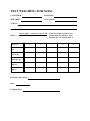
User’s Manual Belt Scale OJ436 OJ:s Vågsystem AB +46 247 13657, +46 70 6756677 / 6856677 Fax. +46 247 145 96 e-mail: [email protected] www.vagsystem.se FRONT PANEL OPERATION. The belt weigher has three different: passwords to access February 2011 Page 1 of 6 PASS 001: Calibrations PASS 002: Configuration PASS 003: Maintenance To gain access to either data area from the working display operate the SELECT key twice until the indicator shows PASS. Press ENTER, then use the and keys to show the appropriate password number; then operate ENTER to show the first parameter in the area accessed. Use SELECT to index through the parameters. Data entry: Having selected the parameter you wish to adjust operate ENTER at which point the first digit flashes on/ off. Use the and keys to modify the digits until the required setting is obtained. Operate ENTER again to steady the value. To exit a data area operate ENTER at the last parameter in every password – EXIT. TARE OF THE BELT WEIGHER. To perform a dynamic tare without entering the password, operate the CLEAR and SELECT keys (CLEAR first) for 3 seconds. Note that the belt must run empty!!! DEAD RANGE is lit when the flow rate is less than the DEAD RANGE setting. The internal dynamic zero is adjusted every 30 seconds by 0.01% of the Loadcell Capacity (LC) during periods within dead range with the belt running empty. An symbol is displayed when the tacho signal is lost i.e. belt stopped. READING OF THE RESETTAABLE TOTAL AND FLOW TIME: Operate TOTAL and the current value is shown in the display, press CLEAR to reset. Operate TOTAL twice to read the actual flow time, press CLEAR to reset. The non-resettable total: Operate SELECT to read the total. Operate FLOW to return to flow rate. This total is resettable within PASS 003 with ENTER - CLEAR - ENTER key sequence. CALIBRATION. February 2011 Page 2 of 6 The flow rate display and the rate of totalisation are determined by the Calibration Factor, parameter CF in password 001. The calibration may be checked and if necessary automatically adjusted i.e. the weigher is re-calibrated as follows: -Enter the parameter DC, Dynamic Calibration, in password 001. -Operate CLEAR. -Pass known weight over weigher (or quantity of material that can be subsequently weighed). -Operate CLEAR to stop the totalisation process. -Check that the totalised reading corresponds to the known test weight. Otherwise operate ENTER and modify the readout to the test weight value and operate ENTER to complete the calibration. You can also execute the calibration as follows: -Check the parameter TT, you will find it in password 003, operate CLEAR to reset. -Pass known weight over weigher (or quantity of material that can be subsequently weighed). -Check the totalised reading in password 003, use the calculation below to determine the divergence: Weigher minus Test weight x 100 Test weight = Divergence in % e.g. 12 300kg - 12 600kg x 100 12 600kg = - 2,38% If the weigher needs to be re-calibrated, the Calibration Factor must be directly adjusted in the parameter CF. Enter the parameter CF and adjust the current value with the same percentage as the divergence. How? See page 1, Data Entry. e.g. CF = 40.00 - 2,38% = 39.05 If you only need to calculate a new calibration factor, use this simple formula: DISPLAYED TOTAL / ACTUAL TOTAL x CF = NEW CF MAINTENANCE. February 2011 Page 3 of 6 Password 003, this section provides a facility for monitoring the input signals for the loadcell and tachometer. T: Non-resettable total, which may be reset with Enter - Clear - Enter key sequence. HZ: Tacho speed, multiply by 0,0236 to read the beltspeed in m/ s. e.g. 76 x 0,0236 = 1,8 m/s. ADC: Analog to Digital Convertor output 0-65,535 divided by 4. This is the weight input signal before any tare or calibration have been made i.e. the raw weight reading. LCS: Load Cell Signal, the weight input signal displayed in Kg before any tare or calibration adjustments have been made. It is the gross weight applied to the loadcell within the range defined by the LC setting. These values should be written down in the list of specifications after start-up of the belt weigher, should any malfunction occur at some time, check the current values and compare with those written down. The following maintenance data data is also accessable in this area: T: Non-resettable total, may be reset operating ENTER, CLEAR and ENTER again. PC: Pulse Counter, tacho pulse counter facility. Operate CLEAR key to start the counter. Operate ENTER key to stop. WT: Weight input signal, shows the weight input signal in Kg with the tare weight removed, i.e. LCS – Internal Dynamic Zero. T: Total in 3 decimal place - Kgs TT: Test Total, a totaliser that can be used for test weighing purposes. Always displayed to a 1kg resolution. Operate CLEAR to reset. RT: Belt Running Time, indicates the lenght of time, in hours, thet the belt has been running since the timer was last reset. Operate CLEAR to reset. OVERVIEW OF THE PARAMETERS. February 2011 Page 4 of 6 PASS 001 TS FL DR TP DT CP DC CF CC PSET EXIT = Tacho Simulator, set to 0 with external tachometer. = Flow, used to determine at what level DR parameter below should be set. = Dead Range, specifies the minimum flow rate below which readings are ignored. = Tare Pulses. = Dynamic Tare. = Calibration Pulses. = Dynamic Calibration. = Calibration Factor. = Calibration Counter. = Password Set, determines the password code for access to this section (001). = Exit, allows the user to return to normal display mode upon operation of ENTER. PASS 002 MO = Model Version, with affix – : basic, A : Analogue. LC = Load Cell Capacity. WF = Weigher Filter. SF = Speed Filter PG = Pre-Gain, (7). BRL = Belt Running Level, set to eliminate spurious pulses when belt is stopped. IN = Increment (Display). UP = Update Rate (mS, Display). FDP = Flow Rate Decimal Place. RTDP = Resettable Total Decimal Place. NTDP = Non-Resettable Total Decimal Place SDP = Static Decimal Place i.e. LC, OP, WT and DT (when idle). TONS Yes = tonnes, No = kg. OP = Output Pulse. T1 = Trip, determines the flow level at which the T1 relay output switches to on. T2 = If zero, healthy signal. Or else the same function as T1. TL = Flow Time Level. Zero setting is used to select the DR as flow level. D2 = Digital Input 2 Operation BR = Baud Rate CS = Communication Standard (determines the serial link i.e. RS485/422 or RS232) ADDR= Address, sets the units address code number SM = Serial Mode (SABUS/TRANS/REP/ModbusASCII/ModbusRTU). *SP = Span, maximum flow reading. *Analogue Parameters, only when PR436 = A. *AZ = Analogue Zero. *AR = Analogue Range. PSET = Password Set, determines the password code for access to this section (002). EXIT = Exit, allows the user to return to normal display mode upon operation of ENTER Password 003 T HZ PC ADC LCS WT T TT RT PSET EXIT = Non-Resettable Total, which may be reset with Enter - Clear - Enter key sequence. = Tacho Speed. = Pulse Counter, tacho pulse counter facility. = Analogue to Digital Convertor. = Load Cell Signal. = Weight input signal in kg with tare weight removed. = Total to 3 decimal places, only if unit set to display Tonnes. = Test Total Kgs, for test weighing, reset with Clear. = Belt Running Time in hrs, accumulates whenever tachosignal is live. Clear = reset. = Password Set, determines the password code for access to this section (003). = Exit, allows the user to return to normal display mode upon operation of ENTER WIRING DIAGRAM. OJ436: Colour: February 2011 Page 5 of 6 Connectionbox: Colour: 10-p connector: +VE Red 1 Red 1 +SE Grey 2 Grey 8 +IN Green 3 Green 2 Loadcell -IN Yellow 4 Yellow 3 -SE Pink 5 Pink 10 -VE Blue 6 Blue 4 +V Brown/ white +V Brown/ white 5 SG Black SG Black 6 0V Violet 0V Violet 7 D1 Digital Input (Print report) D2 Digital Input (Remote tare/clear total) T1 Trip Output T2 Healthy Signal or Trip T3 Pulse Output 1 Blue Green T4 Belt Stopped Output 2 Green Blue 3 White Red A1+ Analogue output 4 Red White 5 Grey Brown 6 Black Black Tacho Loadcell/ box: Colour: 1250: G- +R -T Serial Link GD E N 85-264ac L + Tacho/ box: Colour: +V Brown SG Black 0V Blue 10-36dc - 9 = Shield EQUIPMENT FAULTS. February 2011 Page 6 of 6 Out of Range This condition occurs if the load cell input signal is outside the full scale input range as defined by the amplifier pre-gain (parameter PG), or if the tacho input is above 500Hz. Display shows ‘ADC-SAT+’ Indicates that the input is outside the range in the positive direction. Display shows ‘ADC-SAT-’ Indicates that the input is outside the range in the negative direction. Display shows ‘OV SPEED’ Indicates that the tacho input is outside the 500Hz range. Failures Although unlikely, the following types of equipment failure are possible. In all cases the unit may be returned to us for repair. No response No indication or response of any kind. Possibly a supply circuit failure. A soldered-in PCB (Printed Circuit Board) fuse may need replacing as a result. Alternatively the fuse failure could be the only failure. Display shows ‘REGFAULT’ This occurs if the load cell supply is overloaded due to wiring or load cell faults, or if the internal 10V supply regular has failed. Display shows ‘SENSE ER’ This occurs if the sense voltage (between the +SE and the -SE load cell terminals) has varied by more than 0.3V with respect to the internal value which was stored at the last Tare operation. Display shows ‘ERR nnnn’ where nnnn Fault Code Number This indicates that a microprocessor fault has occurred. It may help to report the Fault Code Number to us when returning the unit for repair. Lost Pass Numbers: Restore Factory Settings In the event of the passwords being lost the original factory default setting of 1, 2 and 3 can be reloaded by holding down the SELECT and ENTER keys for approximately 30 seconds (operate ENTER key first). After this time the display changes to read PASS. The password number will the have been restored to 1, 2 and 3. TEST WEIGHING FOR OJ436 CUSTOMER: POSITION: WEIGHER: LOCATION: NOTES: (belt weigher - reference scale) x 100 Diff % = reference scale Test No. CF OJ436 Kg Reference Kg Diff. Kg Diff. % Reference scale used: Date: Completed by: 1 2 If the belt weigher registers less weight than the reference scale, decrease the CF with the diff. % 3 4 5