1
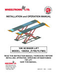
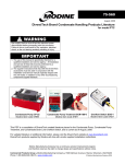
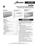
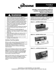
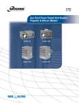
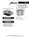
2-525.2 5H75690A August, 2010 installation and service manual electric unit heaters model HER Inspection on Arrival 1.Inspect unit upon arrival. In case of damage, report it immediately to transportation company and your local Modine sales representative. 2.Check rating plate on unit to verify that power supply and motor specification requirements meets available electric power at the point of installation. 3.Inspect unit upon arrival for conformance with description of product ordered (including specifications where applicable). General Information WARNING Installation and wiring of these electric unit heaters must conform to all applicable local codes and the National Electric Code. Wiring of these electric unit heaters should only be performed by a qualified electrician. Improper installation, adjustment, alteration, service or maintenance can cause property damage, injury or death, and could cause exposure to substances which have been determined by various state agencies to cause cancer, birth defects or other reproductive harm. Read the installation, operating and maintenance instructions thoroughly before installing or servicing this equipment. IMPORTANT The use of this manual is specifically intended for a qualified installation and service agency. A qualified installation and service agency must perform all installation and service of these appliances. THIS MANUAL IS THE PROPERTY OF THE OWNER. PLEASE BE SURE TO LEAVE IT WITH the owner WHEN YOU LEAVE THE JOB. special precautions / table of contents / SI (METRIC) CONVERSION FACTORS Special Precautions THE INSTALLATION AND MAINTENANCE INSTRUCTIONS IN THIS MANUAL MUST BE FOLLOWED TO PROVIDE SAFE, EFFICIENT AND TROUBLE-FREE OPERATION. iN ADDITION, PARTICULAR CARE MUST BE EXERCISED REGARDING THE SPECIAL PRECAUTIONS LISTED BELOW. FAILURE TO PROPERLY ADDRESS THESE CRITICAL AREAS COULD RESULT IN PROPERTY DAMAGE OR LOSS, PERSONAL INJURY, OR DEATH. THESE INSTRUCTIONS ARE SUBJECT TO ANY MORE RESTRICTIVE LOCAL OR NATIONAL CODES. HAZARD INTENSITY LEVELS 1.DANGER: Indicates an imminently hazardous situation which, if not avoided, WILL result in death or serious injury. 2.WARNING: Indicates a potentially hazardous situation which, if not avoided, COULD result in death or serious injury. 3.CAUTION: Indicates a potentially hazardous situation which, if not avoided, MAY result in minor or moderate injury. 4.IMPORTANT: Indicates a situation which, if not avoided, MAY result in a potential safety concern. DANGER Appliances must not be installed where they may be exposed to a potentially explosive or flammable atmosphere. WARNING 1.Disconnect power supply before making wiring connections to prevent electrical shock and equipment damage. 2.All appliances must be wired strictly in accordance with wiring diagram furnished with the appliance. Any wiring different from the wiring diagram could result in a hazard to persons and property. 3. Ensure that the supply voltage to the appliance, as indicated on the serial plate, is not 5% greater than rated voltage. 4.When servicing or repairing this equipment, use only factory-approved service replacement parts. A complete replacement parts list may be obtained by contacting Modine Manufacturing Company. Refer to the rating plate on the appliance for complete appliance model number, serial number, and company address. Any substitution of parts or controls not approved by the factory will be at the owner's risk. important To check most of the Possible Remedies in the troubleshooting guide listed in Table 7.1, refer to the applicable sections of the manual. Table of Contents General Information.................................................................... 1 Special Precautions.................................................................... 2 SI (Metric) Conversion Factors . ................................................ 2 Unit Location ............................................................................. 3 Unit Mounting............................................................................. 3 Installation.................................................................................. 4 Electrical Connections........................................................... 4 Start-Up Procedure..................................................................... 5 Operating Sequence.............................................................. 5 Maintenance............................................................................... 5 Dimensional Data...................................................................... .6 Performance Data...................................................................... 6 Motor Specifications................................................................... 6 Service & Troubleshooting.......................................................... 7 Warranty......................................................................Back Page SI (Metric) Conversion Factors Table 2.1 To ConvertMultiply ByTo Obtain "W.C. 0.24 kPa psig 6.893 kPa °F (°F-32) x 0.555 °C inches 25.4 mm feet 0.305 meters CFM 0.028 m3/min CAUTION 1. Be sure no obstructions block air intake or discharge of the appliance. 2. Do not install appliance outdoors. 3. Do not install appliance closer than 12 inches to combustible materials in any direction. 4. The bottom of the appliance must be at least 8 feet above the floor. 5. Do not attach duct work, air filters, or polytubes to any appliance. 6. Ensure that the supply voltage to the appliance, as indicated on the serial plate, is not 5% less than the rated voltage. 7. Do not reuse any electrical component which has been wet. Such component must be replaced. 2 2-525.2 To ConvertMultiply ByTo Obtain CFH 1.699 m3/min Btu/ft3 0.0374 mJ/m3 pound 0.453 kg Btu/hr 0.000293 kW/hr gallons 3.785 liters psig 27.7 "W.C. unit location / UNIT MOUNTING Unit Location DANGER Appliances must not be installed where they may be exposed to a potentially explosive or flammable atmosphere. CAUTION 1. Be sure no obstructions block air intake or discharge of the appliance. 2. Do not install appliance outdoors. heater above the maximum mounting height shown in Table 6.2 or below eight feet. Two tapped holes (3/8" - 16) in the top of the unit are provided for unit heater suspension. Suspension can be made with threaded rods, pipes, or ceiling hanger brackets furnished by others. See Figure 6.1 for hanger hole locations and Figure 3.3 for suspension methods. NOTE: A pipe hanger adapter kit, shown in Figure 3.3 is available as an accessory from Modine, or can be selffabricated. Kit consists of two drilled 3/4" I.P.S. pipe caps and two 3/8" - 16 x 1-3/4" capscrews to facilitate threaded-pipe suspension. One kit is required for mounting each unit. Wall-Mounting Bracket In locating units, consider general space-heating requirements of the area. Unit heaters should be located so they discharge air nearly parallel to exposed walls. Arrange units so they do not blow directly at occupants. Interference of air streams by columns, beams, partitions, or other obstructions should be avoided as much as possible. In multiple unit installations, arrange units so that each supports the air stream of the next unit, thus creating circulatory air movement in the area. See Figure 3.1. A large portion of the heated air should be directed toward the side of the building exposed to prevailing winds. Height at which unit heaters are installed is critical. Maximum mounting heights for all units are listed in Table 6.2. The maximum mounting height for any unit is that height above which the unit will not deliver heated air to the floor. The maximum mounting heights must not be exceeded in order to assure maximum comfort. For easier installation of Model HER electric unit heaters, where ceiling suspension is not feasible, a wall-mounting bracket kit is available. The bracket saves installation time, has a built-in wall clearance, and provides an inexpensive and convenient wall mounting method. The one-point suspension, shown in Figure 3.2, permits swiveling the unit 90 degrees horizontally for most effective air direction. Refer to separate bulletin furnished with the kit for bracket assembly and installation. Refer to Table 6.2 for maximum mounting height. Minimum mounting height is eight feet. Figure 3.1 - Typical Unit Locations Figure 3.1 - Typical Unit Locations Figure 3.3 - Ceiling Suspension Methods Unit MOUNTING CAUTION 1. Do not install appliance closer than 12 inches to combustible materials in any direction. 2. The bottom of the appliance must be at least 8 feet above the floor. 3. Do not attach duct work, air filters, or polytubes to any appliance. It is recommended that adequate service access in excess of 18 inches be provided for the motor and fan. Be sure the means of suspension is adequate to support the weight of the unit (see note). Clearances to combustibles as specified above must be strictly maintained. Do not install unit 2-525.2 3 installation Electrical Connections WARNING 1.Disconnect power supply before making wiring connections to prevent electrical shock and equipment damage. 2.All appliances must be wired strictly in accordance with wiring diagram furnished with the appliance. Any wiring different from the wiring diagram could result in a hazard to persons and property. 3. Ensure that the supply voltage to the appliance, as indicated on the serial plate, is not 5% greater than rated voltage. CAUTION 1. Ensure that the supply voltage to the appliance, as indicated on the serial plate, is not 5% less than the rated voltage. 1.Installation of wiring must conform with local building codes, or in the absence of local codes, with the National Electric Code ANSI/NFPA 70 - Latest Edition. Unit must be electrically grounded in conformance to this code. In Canada, wiring must comply with CSA C22.1, Part 1, Electrical Code. 2. Wire must be Type TW insulated for 60° C (140° F) or better. 3.Two copies of the unit wiring diagram are provided with each unit. One is located in the bottom control compartment access panel and the other is supplied in the literature packet. Refer to this diagram for all wiring connections. Figure 4.1 - Control Panel Viewed from Unit Bottom 4.Make sure all multi-voltage components (motors, transformers, etc.) are wired in accordance with the power supply voltage. 5.The power supply to the unit must be protected with a fused or circuit breaker switch. 6.The power supply must be within 5% of the voltage rating and each phase must be balanced within 2% of each other. If not, advise the utility company. 7.External electrical service connections that must be installed include: a. Supply power connection (208, 240, or 480 volts). b. C onnection of thermostats, or any other accessory control devices that may be supplied. 8. Additional electrical wiring details are as follows: 1. Control wiring should be No. 14 AWG (American Wire Gauge). 2.Total line amperes in Table 4.1 includes fan motor and element current (FLA). 3. All 480 volt three-phase units have built-in transformers and fuses. 4. All contactor coils are rated at 208-240 volts. 5. F use blocks with fuses are factory installed on all 480 volt three-phase units to protect motor and transformer. 6. M odels HER200 and HER250 with 208- or 240-volt three phase power supply have two contactors. Summer/Winter Switch A summer/winter toggle switch kit is available for field installation. In the winter position the thermostat will cycle the fan on and off with the heating elements. In the summer position the fan runs continuously while the heating elements are controlled by the thermostat. Refer to separate bulletin included in the kit for installation and wiring. Table 4.1 - Wiring Data CONTROL TERMINAL BLOCK Model Power Size Code Supply Voltage Total Min. Wire Min. Conduit Control Box Amps* Size (AWG) Size Volume (cm3) 11 208V/1ph 24.5 8 12 240V/1ph 21.3 10 31 208V/3ph 14.3 32 240V/3ph 12.5 ELEMENT CONNECTORS 33 480V/3ph 6.5 14 11 208V/1ph 36.5 6 1 CONTACTOR 12 240V/1ph 31.7 8 3/4 31 208V/3ph 21.3 32 240V/3ph 18.5 33 480V/3ph 9.5 14 11 208V/1ph 49.4 4 12 240V/1ph 42.9 6 31 208V/3ph 29.0 32 240V/3ph 25.3 33 480V/3ph 31 208V/3ph 32 POWER TERMINAL BLOCK 50 75 100 Figure 4.2 - Rear View with Unit Mounted T-stat 125 150 200 250 12 10 3/4 1/2 1/2 1 8 3/4 13.3 12 1/2 36.0 6 1 240V/3ph 31.4 8 3/4 33 480V/3ph 16.3 10 1/2 31 208V/3ph 42.9 32 240V/3ph 37.4 6 1 33 480V/3ph 19.3 10 1/2 31 208V/3ph 56.8 3 1-1/4 32 240V/3ph 49.4 4 1 33 480V/3ph 25.3 8 3/4 31 208V/3ph 70.7 2 32 240V/3ph 61.4 3 33 480V/3ph 31.4 8 17,563.11 30,331.21 1-1/4 3/4 *N EC fuse requirements are 125 percent of total amperes. Check with local code. 4 2-525.2 START-UP PROCEDURE / MAINTENANCE Figure 5.1 - Exposed Side of Electric Unit Heater Initial Start-Up 1. S et thermostat above room temperature. 2. Turn on power to the unit. 3. Adjust the air deflector blades for desired heat distribution. All horizontal blades should be kept open a minimum of 45° as measured from vertical. 4. R un the unit through several cycles by raising and lowering the thermostat setting to assure proper sequence of operation. 1 2 Operating Sequence 3 The operation of Modine electric unit heaters is governed by an electrical contactor which is controlled by a thermostat. The contactor completes the electric circuit to the heating elements when the thermostat “calls” for heat. The fan motor is also activated when the thermostat “calls” for heat. When the thermostat is satisfied, the fan motor stops and the contactor opens the circuit to the heating elements. Routine Unit Maintenance 1. Heating elements 2. Adjustable air deflectors 3. Overheat control important Start-up and adjustment procedures should be performed by a qualified service agency. Prior to Operation Although this unit has been inspected and tested at the factory, the following procedures should be performed to assure proper on-site operation: 1. Check fan clearance. Fan should not contact casing when spun by hand. 2. Check all electrical connections to be sure they are secure, and in accordance with the wiring diagram. 3. Check firmness of unit suspension. Tighten all fasteners, if necessary. 4. Make sure fuses are installed in units that require them. Safety Devices Under average conditions, it is recommended that unit heaters be serviced at least once a year and checked out prior to the heating season. In excessively dirty atmospheres, service should be performed more often. 1. Disconnect power supply to the unit before performing any of the following maintenance or inspection procedures. 2. O pen hinged door at the bottom rear of the unit by loosening the retaining capscrew. Lowering the door will reveal the unit contactors, fuses, transformers, and their electrical connections. Check all components and wiring inside the unit for firm connections and/or wear. 3.Tighten fan guard and motor bracket. Check fan for proper clearance, free rotation, and firm connection to motor shaft. Clean fan blade with detergent or compressed air. 4. F an motor is permanently lubricated for normal operation. Under severe conditions, lubricate with non-detergent SAE 20 motor oil. 5. R outine cleaning of the unit casing and louvers is recommended to remove dirt, grease, or corrosive substances that may damage the finish. Rusted or corroded spots on the louvers or casing should be sanded and repainted. To remove, push louvers against retaining coil spring and pull out at opposite tapered end. 6. Check entire electrical system before every heating season. The overheat control, mounted on the left inner side panel (See Figure 5.1), will interrupt power to the unit contactor in the event of overheating. It is a single-pole, single-throw switch, with an automatic reset. The switch will permit the motor to continue operation and cool the heater while power to the elements is interrupted. This overheat control should operate only when something is seriously wrong with the unit. When this control operates, correct the difficulty immediately or serious and permanent damage may result. The motor for the circulating air fan has internal thermal overload protection. If for any reason the motor overheats, the thermal protector will shut it off. The motor will restart automatically when it has cooled. 2-525.2 5 DIMENSIONAL / PERFORMANCE DATA Figure 6.1 - Dimensions (inches) Table 6.1 Outline Dimensions (inches) Model Size (2) MOUNTING HOLES 3/8"-16 N.C. TAP A C G Dimension 50 - 75 MINUMUM CLEARANCES, 12" TO SIDES AND TOP, 24" TO BOTTOM F G B O M K A H D L APPROX. OPENING 7/8" DIA FOR CONTROL FOR POWER SUPPLY 100 - 150 200 - 250 A 16-7/8 16-7/8 18-7/8 B 20-7/8 20-7/8 24 C 14-3/4 14-3/4 20 D 14-1/2 14-1/2 16-1/2 E 13 13 16 F 8-7/8 9-5/8 12-5/8 G 13-1/2 13-1/2 15-1/2 H 20-1/4 21-1/4 26-1/2 K 2-1/4 2-1/4 3-1/4 L 3-1/4 3-1/4 4-1/4 M 2-1/4 2-1/4 2-1/2 O 12-3/4 12-3/4 14-1/2 Fan Dia. 12 12 14 Approx. Shipping Wt. (lbs.)* 52 74 98 Table 6.2 - Performance Data Heating Capacity Air Data Model Size kW Btu/hr Inlet Airflow (CFM) Temp Rise (°F) Heat Throw (ft.) Max. Mounting Height (ft.) 50 5 17,100 530 30 14 8 75 7.5 25,600 530 45 14 8 100 10 34,100 830 38 20 9 125 12.5 42,700 830 48 20 10 150 15 51,200 830 57 20 10 200 20 68,200 1300 49 25 11 250 25 85,300 1300 61 25 12 ➀ With 70°F ambient air. and louvers directed to the floor at 45°. Table 6.3 - Motor Specifications Model Size HP 50 - 75 1/40 100 - 250 1/15 Voltage 208-230V/60Hz/1ph Amps ➁ RPM Motor Type Bearing Type 0.50 1550 1.28 1050 Totally Enclosed, Shaded Pole, Thermal Overload Protection Sleeve ➁ Amp draw shown is for the motor only. For total unit amp draw, refer to Table 4.1. 6 2-525.2 SERVICE & TROUBLESHOOTING WARNING CAUTION When servicing or repairing this equipment, use only factory approved service replacement parts. A complete replacement parts list may be obtained by contacting Modine Manufacturing Company. Refer to the rating plate on the unit for complete unit substitution of parts or controls not approved by the factory will be at the owner’s risk. Replacement parts can be obtained from Modine by submitting the model number, power code, control code and serial number shown on the rating plate attached to the unit, along with a description of the part. Do not reuse any electrical component which has been wet. Such component must be replaced. important To check most of the Possible Remedies in the troubleshooting guide listed in Table 7.1, refer to the applicable sections of the manual. Table 7.1 - Troubleshooting PROBLEM Unit does not operate Fan operates but element does not heat Elements heat but fan does not operate Insufficient heat POSSIBLE CAUSE(S) REMEDY 1. Electric circuit in open position. 1. a. Turn on switch or thermostat. b. Move thermostat to higher setting. c. Replace fuse or reset disconnect switch. 2. Blown fuses in control compartment. 2. Replace fuses. 3. Defective or incorrect wiring. 3. Check wiring and connections. Refer to diagram inside control panel. 4. Defective thermostat or switch. 4. Check continuity with volt-ohmmeter. Replace defective part if necessary. 5. Defective or burned out control transformer. 5. Check secondary voltage with voltmeter. Replace if necessary. 1. Power interrupted by overheat control. 1. a. Not enough air volume over elements. Louvers must be open at least 45°. b. Check motor rpm against nameplate rating. Replace motor if speed is too slow. c. Defective limit control. Check wiring and connections. Check continuity through control. Replace if necessary. 2. Summer-winter switch in summer position. 2. Change switch position. 3. Defective or incorrect wiring. 3. Check all wiring and connections. See diagram inside control compartment. 4. Blown element fuses on HER200 and HER250 w/208 or 240V-3ø power supply. 4. Replace element fuses. 1. Fan motor failure. 1. a. Check for loose electrical connections. Check wiring with diagram in control compartment. b. Repair or replace burned out defective motor. c. Voltage too high or too low. Check voltage with voltmeter. 2. Summer-winter switch defective or improperly wired. 2.Check for continuity with volt-ohmmeter. Replace if necessary. 3. Defective or incorrect wiring. 3. Check all wiring and connections. See diagram inside control compartment. 1. Too few units for heat loss. 1. Add more units or increase size of units. 2. Unit mounted too high. 2. Lower units. 3. Fan operates backwards. 3. Repair, replace motor or reverse fan rotation. 4. Burned out element. 4. Disconnect internal wiring and check element resistance with ohmmeter. 2-525.2 7 commercial Warranty Seller warrants its products to be free from defects in material and workmanship, EXCLUSIVE, HOWEVER, of failures attributable to the use of materials substituted under emergency conditions for materials normally employed. This warranty covers replacement of any parts furnished from the factory of Seller, but does not cover labor of any kind and materials not furnished by Seller, or any charges for any such labor or materials, whether such labor, materials or charges thereon are due to replacement of parts, adjustments, repairs, or any other work done. This warranty does not apply to any equipment which shall have been repaired or altered outside the factory of Seller in any way so as, in the judgment of Seller, to affect its stability, nor which has been subjected to misuse, negligence, or operating conditions in excess of those for which such equipment was designed. This warranty does not cover the effects of physical or chemical properties of water or steam or other liquids or gases used in the equipment. BUYER AGREES THAT SELLER’S WARRANTY OF ITS PRODUCTS TO BE FREE FROM DEFECT IN MATERIAL AND WORKMANSHIP, AS LIMITED HEREIN, SHALL BE IN LIEU OF AND EXCLUSIVE OF ALL OTHER WARRANTIES, EITHER EXPRESS OR IMPLIED, WHETHER ARISING FROM LAW, COURSE OF DEALING, USAGE OF TRADE, OR OTHERWISE, THERE ARE NO OTHER WARRANTIES, INCLUDING WARRANTY OF MERCHANTABILITY OR FITNESS FOR PURPOSE, WHICH EXTEND BEYOND THE PRODUCT DESCRIPTION CONFIRMED BY BUYER AND SELLER AS OF THE DATE OF FINAL AGREEMENT. This warranty is void if the input to the product exceeds the rated input as indicated on the product serial plate by more than 5% on gas-fired and oil-fired units, or if the product in the judgment of SELLER has been installed in a corrosive atmosphere, or subjected to corrosive fluids or gases, been subjected to misuse, negligence, accident, excessive thermal shock, excessive humidity, physical damage, impact, abrasion, unauthorized alterations, or operation contrary to SELLER’S printed instructions, or if the serial number has been altered, defaced or removed. BUYER’S REMEDY FOR BREACH OF WARRANTY, EXCLUSIVE OF ALL OTHER REMEDIES PROVIDED BY LAW, IS LIMITED TO REPAIR OR REPLACEMENT AT THE FACTORY OF SELLER, ANY COMPONENT WHICH Component Applicable Models Heat Exchangers Gas-Fired Units except PSH/BSH Heat Exchangers Low Intensity Infrared Units Compressors Condensing Units for Cassettes Burners Low Intensity Infrared Units Other Components excluding Heat Exchangers, Coils, Condensers, Burners, Sheet Metal SHALL, WITHIN THE APPLICABLE WARRANTY PERIOD DEFINED HEREIN AND UPON PRIOR WRITTEN APPROVAL, BE RETURNED TO SELLER WITH TRANSPORTATION CHARGES PREPAID AND WHICH THE EXAMINATION OF SELLER SHALL DISCLOSE TO HAVE BEEN DEFECTIVE; EXCEPT THAT WHEN THE PRODUCT IS TO BE USED BY BUYER AS A COMPONENT PART OF EQUIPMENT MANUFACTURED BY BUYER, BUYER’S REMEDY FOR BREACH, AS LIMITED HEREIN, SHALL BE LIMITED TO ONE YEAR FROM DATE OF SHIPMENT FROM SELLER. FOR GAS-FIRED PRODUCTS INSTALLED IN HIGH HUMIDITY APPLICATIONS AND UTILIZING STAINLESS STEEL HEAT EXCHANGERS, BUYER’S REMEDY FOR BREACH, AS LIMITED HEREIN, SHALL BE LIMITED TO TEN YEARS FROM DATE OF SHIPMENT FROM SELLER. These warranties are issued only to the original owner-user and cannot be transferred or assigned. No provision is made in these warranties for any labor allowance or field labor participation. Seller will not honor any expenses incurred in its behalf with regard to repairs to any of Seller’s products. No credit shall be issued for any defective part returned without proper written authorization (including, but not limited to, model number, serial number, date of failure, etc.) and freight prepaid. OPTIONAL SUPPLEMENTAL WARRANTY Provided a supplemental warranty has been purchased, Seller extends the warranty herein for an additional four (4) years on certain compressors. Provided a supplemental warranty has been purchased, Seller extends the warranty herein for an additional four (4) years or nine (9) years on certain heat exchangers. EXCLUSION OF CONSUMABLES & CONDITIONS BEYOND SELLER’S CONTROL The above referenced warranty shall not be applicable to any of the following items: refrigerant gas, belts, filters, fuses and other items consumed or worn out by normal wear and tear or conditions beyond Seller’s control, including (without limitation as to generality) polluted or contaminated or foreign matter contained in the air or water utilized for heat exchanger (condenser) cooling or if the failure of the part is caused by improper air or water supply, or improper or incorrect sizing of power supply. “APPLICABLE WARRANTY PERIOD” TEN YEARS FROM DATE OF FIRST BENEFICIAL USE BY BUYER OR ANY OTHER USER, WITHIN TEN YEARS FROM DATE OF RESALE BY BUYER OR ANY OTHER USER, WITHIN TEN YEARS FROM DATE OF RESALE BY BUYER IN ANY UNCHANGED CONDITION, OR WITHIN ONE HUNDRED TWENTY-SIX MONTHS FROM DATE OF SHIPMENT FROM SELLER, WHICHEVER OCCURS FIRST FIVE YEARS FROM DATE OF FIRST BENEFICIAL USE BY BUYER OR ANY OTHER USER, WITHIN FIVE YEARS FROM DATE OF RESALE BY BUYER OR ANY OTHER USER, WITHIN FIVE YEARS FROM DATE OF RESALE BY BUYER IN ANY UNCHANGED CONDITION, OR WITHIN SIXTY-SIX MONTHS FROM DATE OF SHIPMENT FROM SELLER, WHICHEVER OCCURS FIRST TWO YEARS FROM DATE OF FIRST BENEFICIAL USE BY BUYER OR ANY OTHER USER, WITHIN TWO YEARS FROM DATE OF RESALE BY BUYER IN ANY UNCHANGED CONDITION, OR WITHIN THIRTY MONTHS FROM DATE OF SHIPMENT FROM SELLER, WHICHEVER OCCURS FIRST Heat Exchangers/Coils Indoor and Outdoor Duct Furnaces and System Units, PSH/BSH, Steam/Hot Water Units, Oil-Fired Units, Electric Units, Cassettes, Vertical Unit Ventilators Compressors Vertical Unit Ventilators ONE YEAR FROM DATE OF FIRST BENEFICIAL USE BY BUYER OR ANY OTHER USER, WITHIN ONE YEAR FROM DATE OF RESALE BY BUYER IN ANY UNCHANGED CONDITION, OR WITHIN EIGHTEEN MONTHS FROM DATE OF SHIPMENT FROM SELLER, WHICHEVER OCCURS FIRST Burners High Intensity Infrared Units Sheet Metal Parts All Products As Modine Manufacturing Company has a continuous product improvement program, it reserves the right to change design and specifications without notice. Commercial Products Group Modine Manufacturing Company 1500 DeKoven Avenue Racine, WI 53403 Phone: 1.800.828.4328 (HEAT) www.modine.com © Modine Manufacturing Company 2010 Litho in USA