1
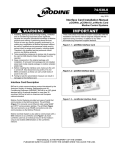
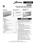
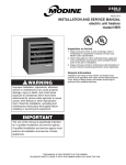
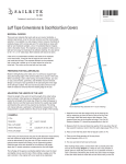
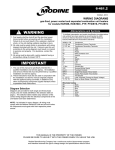
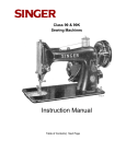
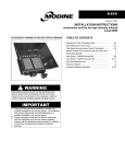
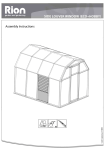
6-598.4
5H079578A
August, 2009
INSTALLATION INSTRUCTIONS
30°, 60°, and 90° downward deflector hoods
and vertical air deflector blades
models HD/HDB, HDS/HDC, PTC, PTS/BTS
ACCESSORY DOWNWARD DEFLECTOR HOOD
WARNING
Gas supply shall be shut-off and the electrical power
disconnected before proceeding with the conversion.
Failure to do so could result in fire, explosion, electrical
shock, or the unit starting suddenly resulting in injury.
VERTICAL AIR DEFLECTOR BLADES
TABLE OF CONTENTS
Instructions – Downward Deflector Hood...……………….2-3
Instructions – Vertical Air Deflector Blades………….………4
IMPORTANT
1. The use of this manual is specifically intended for a
qualified installation and service agency. All installation
and service of these kits must be performed by a
qualified installation and service agency.
2. These instructions must also be used in conjunction
with the Installation and Service Manual originally
shipped with the appliance, in addition to any other
accompanying component supplier literature.
THIS MANUAL IS THE PROPERTY OF THE OWNER.
PLEASE BE SURE TO LEAVE IT WITH THE OWNER WHEN YOU LEAVE THE JOB.
INSTALLATION – DOWNWARD DEFLECTOR HOOD
Deflector Hood Model Application
The 30°, 60° and 90°, Downward Deflector Hoods are
designed for use installed propeller and blower unit heaters.
3.
Assembly/Installation
The recommended procedure for assembly and installation is
described as follows:
1. Before beginning installation of the accessory hood,
remove all of the spring loaded louver blades from the
unit heater on which the hood is to be installed. For
model sizes 30-155, these blades (except for one) will be
relocated in the face of the hood assembly after the hood
is attached to the unit heater. To remove the spring
loaded louver blades, grasp the blade and apply
pressure against the louver blade retaining spring. After
compressing the spring, the tab on the opposite side of
the blade can be removed from the unit, freeing the
blade from the unit.
Note: Do not to lose the louver blade retaining springs as
they will be required later to install the blades into
the hood assembly.
2. Remove the screw on the right lower face of the unit
(when facing the unit air outlet) and attach the hood right
side panel onto the unit with unit screw previously
removed by screwing through the existing hole.
4.
5.
6.
Insert the hood top panel into the top of the unit air outlet
opening (hemmed edge toward the hood outlet, bent
edge toward the unit) with the right side panel on the
outside of hood right top flange (see Figure 2.1). Fasten
the panels with the #10 x ½” self-drilling screws provided.
Attach the hood top to the flange inside the air outlet of
the unit with the #10 x ½” self drilling screws provided,
through the holes in the hood top.
Mount the left side hood panel to the hood top with the
screws provided but do not fasten to the unit casing at
this time. Be sure to mount the left side on the outside of
the hood top flanges.
Model sizes 175-400 require the installation of a vertical
deflector blade bracket and model sizes 350 and 400
require a horizontal deflector blade bracket cross
member be installed. These are shown in Figure 2.3.
Figure 2.3 – Deflector Bracket and Cross Member
175-400 Units
Figure 2.1 - Hood Exploded View
350-400 Units
Only
15.00” Outside Edge to
Center Support Edge
Front View
Figure 2.2 - Hood to Unit Exploded View
7.
8.
2
6-598.4
31.25” Outside Edge to
Outside Edge
In each hood assembly kit for model sizes 30-155 is a
fixed deflector louver blade with serrated tabs at each
end to accept fastening screws (see Figure 2.1). Install
the blade between the outermost hood sides in the
bottom deflector blade position and fasten in place with
#8 x 1” screws provided through the holes in the sides of
the hood and tightening. Locate the blade with the
curved surface up and the rounded corners toward the
outlet of the hood. Rotate the deflector to direct the air
flow in the desired direction, typically perpendicular to the
hood outlet face.
Fasten the lower corner of the left side hood to the unit
face with a self drilling screw. For unit sizes 175-400,
ensure that the assembly is square on the opening and
the dimension from the outside edges and to the center
support match those shown in Figure 2.3.
INSTALLATION – DOWNWARD DEFLECTOR HOOD
9.
If 60° or 90° hoods are being assembled, it is necessary
to connect two 30° sections together for a 60° hood, and
three 30° sections for a 90° hood. See Figure 2.2.
a. For hoods with multiple sections, connect the
sections together by attaching the left and right side
panels to the front of the previous section using the
upper and middle mounting holes on the side plates
with #10 x ½” self drilling screws.
b. Install the hood top between the side panels with the
hemmed edge toward the hood outlet (deflector
blades). Fasten with #10 x 1/2" self drilling screws
provided.
c. Install two or more #10 x ½” self drilling screws
through the top panel of the first hood and into the
top of the second hood top panel where they over
lap. Locate the screws 5” in from each side of the
hood and ¼” back from the seam of the two top
panels.
d. For model sizes 30-155, one fixed blade is supplied
with each kit. Extra fixed blades should be
discarded and only the fixed louver blade from the
first 30° section kit be used (refer to Step 7).
10. For model sizes 30-155, place the louvers removed from
the unit heater in Step 1 into the outlet of the downward
deflector hood. For model sizes 175-400, the deflector
hood kit includes short louver blades and additional
louver retaining springs that are to be installed into the
outlet of the hood. The original longer blades that were
removed from the unit can be saved for future use or
recycled. To install the spring loaded louver blades,
place the louver blade retaining spring over the left end
tab of the blade and guide the spring into the recessed
dimple in the left side panel of the hood. Apply pressure
to compress the spring and then insert the metal tab on
the opposite end of the blade into the tab clearance
holes in the right hand side panel of the hood. Repeat
this procedure for all of the louver blades (see Figure
2.1). Rotate the blades in the desired direction of air
flow. Do not operate the unit with the blades in the
closed position.
11. Attach the included warning label to the lower front of the
discharge hood.
12. Install the screw hole filler plugs to all remaining open
exterior holes.
6-598.4
3
INSTALLATION – VERTICAL DEFLECTOR BLADES
Vertical Deflector Blade Model Application
Figure 4.1 – Vertical Blades Exploded View
The Vertical Deflector Blades are designed for use with
propeller and blower unit heaters. Installation of the
assembly is easiest prior to unit installation.
Assembly/Installation
The following section contains the recommended procedure
for assembly and installation of the vertical louver blade
assembly. Note that model sizes 30-155 feature a single
bank of louvers. Due to the larger discharge opening area,
model sizes 175-200 feature two louver banks and sizes 250400 feature four louver banks (refer to Figure 4.3). As a
result, the instructions below need to be repeated for each
louver bank on unit sizes 175 and larger.
1. Before beginning installation of the accessory vertical
louver blade assembly, remove the top and bottom
spring loaded louver blades from the unit heater on
which the vertical louvers are to be installed. This is to
allow working room for attaching the top and bottom
vertical louver brackets. These blades will be replaced
after the brackets are installed. To remove the spring
loaded louver blades, grasp the blade and apply
pressure against the blade retaining spring. After
compressing the spring, the tab on the opposite side of
the blade can be removed from the unit.
Note: Do not lose the louver blade retaining springs as
they will be required later to reinstall the blades.
2. Place one of the vertical louver mounting brackets on the
bottom edge of the unit discharge opening so that the
flanges of the bracket are facing down with one flange on
the inside edge of the bottom panel on the unit heater
(see detailed view in Figure 4.2). Attach with #10 x ½”
screws supplied with the kit.
3. Repeat the process outlined in Step 2 for the top vertical
louver mounting bracket except note that the flanges of
the bracket should face upward (see Figure 4.2).
4. Replace the two louvers removed from the unit heater in
Step 1. To install the spring loaded louver blades, place
the louver blade retaining spring over the left end tab of
the blade and guide the spring into the recessed dimple
in the left side panel of the heater. Apply pressure to
compress the spring and then insert the metal tab on the
opposite end of the blade into the tab clearance holes in
the right hand side panel of the heater. Rotate the
horizontal blades in the desired direction of air flow. Do
not operate unit with the blades in the closed position.
5. Insert the vertical louver bracket support rod through the
holes provided in the mounting flanges. Secure this
support rod with the acorn push nuts provided.
6. Install the vertical louver blades into the top and bottom
brackets, using the same process as outlined in Step 4.
7. Adjust deflector blades to obtain desired direction of heat
throw. Do not operate the unit with the blades in the
closed position.
Figure 4.2 – Vertical Louver to Unit Installation
Figure 4.3 – Vertical Louvers after Installation
(4) Louver Banks
on Size 350-400
Modine Manufacturing Company has a continuous product improvement program,
and therefore reserves the right to change design and specifications without notice.
Commercial Products Group • Modine Manufacturing Company • 1500 DeKoven Avenue • Racine, Wisconsin, USA 53403-2552
Phone: 1.800.828.4328 (HEAT) • www.modine.com
© Modine Manufacturing Company 2009
6-598.4
Litho in USA