1
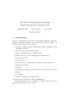
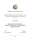
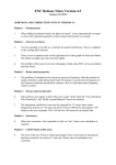
USOOS 75 2 1 25A
United States Patent [191
[11]
Patent Number:
Yamashita et a1.
[45]
Date of Patent:
5,752,125
May 12, 1998
[54] MAINTENANCE MANAGEMENT SYSTEM
FOR IMAGE FORMING EQUIPMENT
Attorney, Agent, or Firm—Beveridge. DeGrandi. Weilacher
& Young. LLP
[75] Inventors: Yuji Yamashita; Jiro Nagira; Yasuhiro
[57]
Hashimoto; Hiroshige Utatsu. all of
Osaka. Japan
ABSTRACT
In a maintenance management system in which communi
cations control devices of electronic photocopiers are con—
nected through public telephone lines or the like with a host
[73] Assignee: Mita Industries Co. Ltd. Osaka, Japan
computer of a maintenance company that manages the
[21] Appl. No.: 716,888
[22] Filed:
Sep. 20, 1996
Photocopiers. preventive-maintenance-oriented. omission
[30]
many times maintenance has been performed or based on a
free instructions for maintenance work are obtained by
determining items of work to be performed based on how
Foreign Application Priority Data
count of copies produced. For example. in the case where
Sep. 28, 1995
[JP]
Japan .................................. .. 7-251376
[51]
[52]
Int. cl.6 ................................................... .. G03G 15/00
US. Cl. ................................................. .. 399/8; 399/24
[58]
Field of Search ............................ .. 399/8. 11. 24-27.
maintenance work to be performed on a ?rst occasion
includes items of work belonging to a work item setting area
of a second order of precedence within a maintenance table.
if items of work that need to be perfonned do not agree with
those specified in the table. items of work of a ?rst order of
399/31. 126; 377/15. 16; 395/184.01
[56]
precedence are added. To achieve this. based on a count at
a moment. a work item sem'ng area in the maintenance table
References Cited
is judged to determine its array number. a maintenance state
U.S. PATENT DOCUMENTS
5,016,059 5/1991 Smeiman
5,077,582 1211991 Kravette et a].
5,200,779
4/1993
8/1994 Yamashita et a1.
11/1994
5,386,271
5,596,390
Nawata ........... ..
Yamada
so that instructions of the second order of precedence are
indicated. Then. the array number of the area is decremented
by one, and the ?ag is judged to be OFF. so that items of
work of ?rst order are added to those of the second order.
Next. duplicated items within the same area are deleted.
. 399/80
.. 399/8
5,343,276
5,369,471
?ag is judged. and the array number is incremented by one.
. . . . . . . .. . . . .
. 399124
.... .. 399/8
. . . . ..
399/8
l/1995 Maekawa et al
.... .. 399/8
1/1997 Sawada ..................................... .. 399/8
whether replacement is necessary or not is judged. and then
it is determined that maintenance on the next occasion
includes items of work of the ?rst and second orders of
FOREIGN PATENT DOCUMENTS
l-271767
10/1989
precedence.
Japan .
Primary Examiner-Robert Beatty
4 Claims, 13 Drawing Sheets
HOST COMPUTER
/
H
D
D
D
D
DEvICE
DEVICE
DEvICE
DEVICE
COPIER
COPIER
COPIER
COPIER
/
/
/
/
P
P
P
P
US. Patent
May 12,1998
Sheet 1 of 13
5,752,125
FIG. 1
T
HOST COMPUTER
H/
/
i
i
D
i
DEVICE
DEVICE
DEVICE
DEVICE
COPIEFI
COPIEFI
COPIEFI
COPIER
US. Patent
FIG.
May 12, 1998
Sheet 2 of 13
5,752,125
US. Patent
May 12, 1998
Sheet 3 0f 13
FIG. 3
5,752,125
18
OPERATION /
5O
PANEL
17
SHEET - PASSAGE
19
COUNT SENSOR
CONTROL
SECTION
MEMORY
SECTION
PAPER FEED
SECTION
21
//
INTERFACE
DEVICE
US. Patent
May 12, 1998
Sheet 4 0f 13
@M§<m/
8.
mmE
\
mm
8
?wmwMm? kmh?t mm
mEOEP
mm
o.V6/06R.
\
\
x
a
w._:zmsao=ow?0I<m“o_2iz.z
#50
5,752,125
US. Patent
May 12, 1998
Sheet 5 of 13
5,752,125
FIG. 5
as
32
K
K
ROM
RAM
38
T
g
39
)
MODEM
34
)
INTERFACE
l_| l-—I 31
K
EXTERNAL
CPU
SETH/AGE
I____
KEYBOARD
\37
< ORT
PRINTER
\
35
36
US. Patent
May 12, 1998
Sheet 6 0f 13
5,752,125
FIG. 6
32
RAM
/
MAINTENANCE TABLE STORING AREA \
41
MAINTENANCE TABLE STORING AREA \M 41
|
I
I
MAINTENANCE TABLE STORING AREA \¥41
43 ~\ USE COUNTER
STORING AREA
WORK ITEM
STORING AREA "\~ 44
43 '"T\ USE COUNTER
STORING AREA
WORK ITEM
STORING AREA '\~- 44
|
|
|
48 T~\ USE COUNTER
STORING AREA
l
I
I
WORK ITEM
STORING AREA "\\~ 44
45 ’“\_ OTHER STORING AREA
US. Patent
May 12,1993
Sheet 7 of 13
5,752,125
/
.UEmm
GEOw
US. Patent
May 12, 1998
Sheet 8 0f 13
5,752,125
FIG. 8
INDICATION
ITEMS OF WORK
REPLACEMENT
REPLACE THE COMPONENT.
CLEANING
CLEAN THE COMPONENT.
LUBRICATION
LUBRICATE THE COMPONENT.
ADJUSTMENT
ADJUST THE COMPONENT.
CHECKING
CHECK THE COMPONENT.
MAINTENANCE
NOT REGARDED AS MAINTENANCE
IGNORED
(REPAIR MAINTENANCE).
* * * *
NO
MAINTENANCE
WORK REQUIRED.
CHECKING /
REPLACEMENT
CHECK THE COMPONENT AND ,
IF NECESSARY , REPLACE IT.
CHECKING /
CLEANING
CHECK THE COMPONENT AND ,
IF NECESSARY , CLEAN IT.
CHECKING /
LUBRICATION
CHECKING /
ADJUSTMENT
CHECK THE COMPONENT AND ,
IF NECESSARY , LUBRICATE IT.
CHECK THE COMPONENT AND ,
IF NECESSARY , ADJUST IT.
CLEANING /
CLEAN AND LUBRICATE
LUBRICATION
LUBRICATION /
ADJUSTMENT
< < < <
> > > >
THE COMPONENT.
LUBRICATE AND ADJUST
THE COMPONENT.
RETURN TO THE HEAD OF THE MAINTENANCE
CYCLE.(NOT AN ITEM OF WORK)
REPEAT THE LAST(PREVIOUS) WORK.
(NOT AN ITEM OF WORK)
US. Patent
May 12, 1998
Sheet 9 of 13
5,752,125
FIG. 9
#5
@
JUDGE TO WHICH AREA THE
CURRENT COUNT
CORRESPONDS TO WHAT
ORDER OF PRECED NCE
THE MAINTENANCE OCCASION
CURRENTLY POINTED TO HAS).
#10
I
L
><=n
#15
I
WHAT IS THE
MAINTENANCE STATE
FLAG FOR THE X-th
OCCASION?
0 (OFF)
# 25
ADD ITEMS OF MAINTENANCE
WORK OF THE X-th OCCASION
TO Z (WORK ITEMS).
1
#30
WHAT IS THE
MAINTENANCE STATE
FLAG FOR THE X-th
OCCASION?
0 (OFF)
# 35 ADD ITEMS OF MAINTENANCE
WORK OF THE X-th OCCASION
1 (ON)
TO 2 (WORK ITEMS).
I
#
X = X _ 1
=
# 45
DELETE DUPLICATED
X > 0
ITEMS OF MAINTENANCE
WORK WITHIN Z.
#55
IS THERE
"REPLACEMENT"
WITHIN 2'?
# 60
NO
I
II
II
(
END
CHANGE 2 TO SIMPLY
"REPLACEMENT".
I
1
US. Patent
May 12, 1998
Sheet 10 of 13
5,752,125
02m
mm
OZm
mv
om.
om
mm
ow
om
mm
om
on
mm
mm
0.0.
om
m?
or
mp
o wop
o om
.GEor
.bPZ2ME30DO
C
N£65: GE: awhm
P.Z_mIEDO
C
X
NE605:
5.752.125
1
2
MAINTENANCE MANAGEMENT SYSTEM
FOR IMAGE FORMING EQUIPMENT
de?ned in the maintenance table. so that the step of main
tenance work for each component is advanced one step
further on every occasion of regular maintenance.
However. a conventional management system in which
maintenance work is performed according to a maintenance
table as described above is defective. because it poses a
BACKGROUND OF THE INVENTION
1. Field of the Invention
The present invention relates to a maintenance manage
problem when a session of regular maintenance takes place
untimely before the completion of one cycle of regular
ment system for image forming equipment. more speci?
cally to a maintenance management system for managing
maintenance of image forming equipment such as electronic
photocopiers in terms of components that require regular
maintenance.
10
replacement. such as photosensitive drums and paper feed
For example. the maintenance cycle of a photosensitive
drum shown in FIG. 14 is so determined that replacement is
performed on every fourth occasion of checking.
Accordingly. if regular maintenance is scheduled to take
place every 50.000 copies as described above. it is natural
ing parts. and components that require regular checking.
such as contact glasses.
2. Description of the Prior Art
that replacement is performed every 200.000 copies.
However. if regular checking is performed every 10.000
In general. regular maintenance of image forming equip
ment such as electronic Photocopiers is performed according
copies. and if completion of each checking session is reg
to service manuals. A service manual lists. for each compo
nent of a copier. items of maintenance work that should be
component. When a predetermined count of copies are
istered in the device attached to a copier as completion of
regular maintenance session. the item of maintenance work
to be performed next time will be indicated as “replacement”
as early as when the third occasion of regular maintenance
supposed to have been produced after the previous regular
is completed. that is. at the count of 30.000 copies.
performed at every predetermined count of copies (for
example. every 100.000 copies) after the replacement of that
20
maintenance occasion. a serviceperson visits a user’s site
To solve this problem. a conventional copier management
where a copier is installed. and. consulting a service manual 25 system. even while indicating the item of maintenance work
for what to do on this occasion of regular maintenance.
to be performed next time as “replacement”. also indicates
the remaining working life of the photosensitive drum by
showing that it is still capable of 170.000 copies and has
performs maintenance work according to the service
manual.
In a certain copier management system. communications
control devices are attached to copiers. and are connected
through telephone lines or other to a host computer installed
30
cation of the item of maintenance work to be performed next
time. This method. however. is far from su?iciently solving
the problem associated with maintenance management
at a maintenance company that manages these copiers. Thus.
the host computer collectively manages data concerning
maintenance of the image forming equipment. In this
system. those devices notify the host computer when to
reached a 15 percent point in its total working life. thereby
preventing untimely replacement based solely on the indi
35
based on how many times maintenance has been performed.
because a serviceperson may overlook relevant indications
perform regular maintenance at every predetermined count
or. in some cases. may be compelled to make delicate
of copies. so that a serviceperson. on receiving such a
noti?cation. visits a user’s site to perform maintenance work
judgements in consideration of his company’s relationship
for the copier installed there. just as described above.
The description above seems to suggest that. in order to
solve the problem. it is more realistic to determine items of
with a user.
FIG. 14 shows a maintenance table as is conventionally
stored in such a host computer. As shown in this ?gure. a
maintenance table is a table listing items of maintenance
work to be performed for each component in each individual
copier. Speci?cally. in a maintenance table. items of work
such as “replacement”. “cleaning”. “lubrication”.
“adjustment”. and “checking" that need to be performed on
the occasions of regular maintenance that take place every
predetermined count of copies are listed component by
component in order of array numbers that indicate the order
of precedence of regular maintenance occasions on which
those items of work are performed.
maintenance work to be performed based on the actual count
45
maintenance work is required. This problem results from the
50
For example. in the case of a contact glass in an original
stand. cleaning is performed at the count of 50.000 copies
after installation or replacement; at the count of 100.000
copies. no maintenance work is required. but. on completion
of the checking at the count of 100.000 copies. the array
of copies. rather than how many times maintenance has been
performed. However. a management method based on the
count of copies is also defective. because. when dealing with
a component like the contact glass shown in FIG. 14. such
a method indicates “cleaning” until the copy count reaches
50.000. but. if the count happens to be 50.001 just when a
serviceperson starts maintenance work. it indicates that no
55
way threshold values are selected in determining when to
perform maintenance. and it often causes. in a conventional
maintenance system. losses of information concerning items
of maintenance work to be performed.
SUMMARY OF THE INVENTION
An object of the present invention is. in a maintenance
management system in which communications control
devices attached to electronic copiers are connected through
public telephone lines to a host computer at a maintenance
number is rewound to the
number. so that cleaning is
performed next time at the count of 150.000 copies. On the
other hand. in the case of a photosensitive drum. no main
tenance Work is required at the count of 50.000 copies after 60 company managing those copiers. to make it possible to
provide preventive-maintenance-oriented. omission-free
installation or replacement; at the count of 100.000 copies.
instructions for maintenance work. by solving such a sys
adjustment is performed; at the count of 150.000 copies. no
tem’s problems in determining items of maintenance work
maintenance work is required; on the occasion of the check
based on how many times maintenance has been performed
ing at the count of 200.000 copies. replacement is
performed. thereby rewinding the array number to the initial 65 or based on the count of copies.
number. In the same way. steps of maintenance work for an
To achieve the above object. according to the present
upper paper feed roller and other components are also
invention. a maintenance management system that manages
5.752.125
3
4
items of maintenance work to be performed for each com
junction with the preferred embodiments with reference to
the accompanied drawings in which:
ponent of image forming equipment is provided with a work
FIG. 1 is a block diagram showing the outline of the
item storing means. a work item judging means. and a work
management system embodying the present invention;
item determining means. In a communications management
system for image forming equipment such as a management
system comprising communications control devices for out
putting management data and a host computer connected to
the communications control devices through a communica
tions network in order to collectively manage the manage
ment data. the maintenance management system of the
FIG. 2 is a cross-sectional view schematically showing a
copier;
FIG. 3 is a block diagram showing the control system of
the copier;
FIG. 4 is a block diagram showing the construction of a
communications control device;
present invention can be constructed as a software program
FIG. 5 is a block diagram showing the construction of a
within the host computer.
The work item storing means sets items of maintenance
work that should be performed for each component regularly
at every predetermined count of use of image forming
equipment. and stores di?erent work item setting areas in
order of precedence of regular maintenance occasions. The
work item storing means is secured. for example. in the work
RAM in a host computer. The work item judging means
judges. based on an order of precedence of a work item
setting area referred to at a particular moment. to which
work item setting area belongs an item of work to be
performed on a next occasion. The work item determining
20
procedure;
means determines. based on how many times maintenance
has been performed for the image forming equipment until
host computer;
FIG. 6 is a schematic diagram showing the items stored in
the RAM of the host computer;
FIGS. 7A to 7C are diagrams showing examples of
maintenance work items. maintenance state ?ags. and pre
ventive maintenance work items;
FIG. 8 is a diagram showing an example of items of work;
FIG. 9 is a ?owchart showing the maintenance manage
ment operation of the host computer;
FIG. 10 is a diagram showing one management operation
25
FIG. 11 is a diagram showing the management operation
a particular moment. whether or not an item of work that
belongs to a work item setting area having an order of
procedure following the one shown in FIG. 10.
FIG. 12 is a diagram showing another management opera
precedence prior to a result given by the Work item judgment
tion procedure",
FIG. 13 is a diagram showing yet another management
means should be added to an item of work to be performed
on a next occasion.
operation procedure; and
For example. suppose that. in the work item storing
means. work item setting areas representing “cleaning".
FIG. 14 is a diagram showing an example of conventional
maintenance table.
“lubrication”. “adjustment” and “replacement” are arranged
in this order for a paper feed clutch. which is one component 35
of a copier. On the ?rst occasion of maintenance. even if the
work item judging means judges that “lubrication”. which is
the second in order of precedence. is to be performed on the
next occasion of maintenance. the work item determining
means determines that “cleaning” is also performed in
addition to “lubrication”. because. at that moment.
DESCRIPTION OF THE PREFERRED
EMBODIMENTS
Hereinafter. an embodiment of the present invention as
40
applied to a copier management system will be described
with reference to the drawings. FIG. 1 schematically shows
an example of the copier management system. As shown in
this ?gure. the copier management system comprises a host
“cleaning”. which is the ?rst in order of precedence. has not
computer H installed at a maintenance company to manage
yet been performed.
maintenance. and a plurality of copiers P. Each copier P is
equipped with a communications control device D. which is
connected through a public telephone line T to the host
Further. when the work item judging means judges that a
component needs to be replaced. the work item determining
means determines that only replacement of the component is
performed. This is because. when a component is replaced.
45
computer H.
FIG. 2 shows the construction of the copier P. As shown
in this ?gure. the copier Pis provided with an optical system
cleaning or other items of maintenance work are meaning
2 fitted in the upper part of the body 1. The optical system
less.
The work item setting areas in the work item storing 50 2 is for reading an original and comprises a light source.
means are usually set according to the count of use that
mirrors. lens units. and other components. In the central part
corresponds to a regular maintenance cycle. which in turn is
determined based on the worldng lives of components.
of the copier body 1 is provided an image forming section
According to this method. however. it sometimes happens
that. for some reason or other. the items of work belonging
to the work item setting area of the next order need to be
3 for forming an image with toner based on the read original.
The image forming section 3 has a photosensitive drum 4. on
the surface of which an electrostatic latent image is formed.
performed before the next occasion of regular maintenance.
Arranged around the photosensitive drum 4 are a main
charger 5. a developing unit 6. a separation charger 7. and a
To cope with such a situation. preventive maintenance is
essential. Therefore. in the present invention. to make it
cleaning unit 8.
In the lower part of the copier body 1 is provided a paper
possible to perform preventive maintenance without fail. the
feed section 9. The paper feed section 9 comprises a bypass
table 10 that is disposed in the right-hand part of the copier
body 1 shown in FIG. 2. a plurality of paper feed cassettes
items of work that should be performed on a particular
occasion are set in the work item setting areas in anticipa
tion.
11 arranged vertically in the lower part of the copier body 1.
and a paper transfer unit 12 for transferring paper sheets
BRIEF DESCRIPTION OF THE DRAWINGS
65 stocked in the bypass table 10 or paper feed cassettes 11 to
the image forming section 3. Arranged on the downstream
This and other objects and features of this invention will
side of the image forming section 3 along the paper transfer
become clear from the following description. taken in con
5.752.125
5
6
direction are a paper ejecting conveyor 13 for conveying
paper sheets to the left-hand part of the copier shown in FIG.
2. a ?xing unit 14 for ?xing a toner image on paper by
As shown in FIG. 6. in the RAM 32 of the host computer
H are provided maintenance table storing areas 41 for
storing maintenance tables 40 serving as work item setting
areas in which items of regular maintenance work are stored
in order of precedence of regular maintenance occasions. use
counter storing areas 43 for storing counts of use of
fusion. ejecting rollers 15 for ejecting paper sheets after
image ?xation. and a ejected-paper tray 16 for stocking
ejected paper sheets.
The copier body 1 is further equipped with a control
section 17 shown in FIG. 3. The control section 17 is
components. work item storing areas 44 for storing data
representing the items and types of work performed by a
constructed as a microcomputer system including a CPU. a
RAM. a ROM. a variety of drivers. and a variety of I/O
ports. and an operation panel 18 is connected to it. As shown
together as well as the array numbers on that occasion and
serviceperson on the previous maintenance occasion
the array numbers speci?ed for the next occasion. and areas
45 for storing other information. These areas are secured
separately for each of the copiers P that are connected to the
host computer H.
Note that there are three types of maintenance work that
in FIG. 2. the operation panel 18 is disposed on the upper
surface of the copier body 1. and includes an input keypad
section and a display section composed of liquid crystal
display devices. light emitting diodes. or other.
To the control section 17. a memory section 19 for storing
a variety of operation data is also connected. The memory
section 19 stores. for example. the total count of copies
produced by the copier body 1. Also connected to the control
section 17 are a sheet-passage count sensor 20 for counting
how many images have been formed. and a paper feed
section 9 for feeding paper from paper feed cassettes 11.
Actually. a plurality of sheet-passage count sensors 20 are
a serviceperson performs: “regular maintenance” which is
performed regularly at every determined count of copies.
“repair maintenance” which is performed to cope with
occasional troubles. and “regular and repair maintenance"
20
As shown in FIG. 7A. the maintenance table 40 is a table
arranged in appropriate positions along the paper feed path
from each paper feed cassette 11 through the image forming
section 3 and the ?xing unit 14 to the ejected-paper tray 16.
listing items of maintenance work to be performed for each
component of each copier P. Speci?cally. in the maintenance
25
so that. when a correct passage of a paper sheet is detected.
30
sensor 20 is transmitted to that device D.
The copier management device D. which serves to trans
others. Items of maintenance work are displayed on the CHI‘
35
connected to a CPU 23. The CPU 23 is formed as a so-called
gram shown in FIG. 9. To help with judgments that need to
be made during the execution of the program. ?ags indicat
ing states of maintenance are provided. as shown in FIG. 7B.
In this ?gure. "1” represents “ON“. and “0" represents
“OFF”. The program shown in FIG. 9 will be described in
detail later.
For example. in the case of a paper feed clutch. an
(or telephone set) 30 is let to pass circuitously through the
45
device D does not answer the call but transfers it to the
facsimile machine or telephone set. Accordingly. in the
management system of this embodiment. the host computer
H cannot originate a call to the devices D. Alternatively. the
management system may be so designed that. by use of a
dedicated telephone line. a line switching device. or other
means. the host computer H originates a call to read and
35 at a predetermined timing.
The items of work stored in the above described mainte
nance table 40 are performed in accordance with the pro
microcomputer system. and is connected to an NCU
(network control unit) 24. a ROM 25. a RAM 26. and a clock
IC 27. The NCU 24 is connected to a modem 28. and the
modem 28 is in turn connected to a telephone line T.
Note. however. that it is not practical to use the telephone
line T exclusively for the device D of the copier. In reality.
as shown in FIG. 4. a telephone line for a facsimile machine
device D. and the device D is set for transmission only. so
that. when a call is received through the telephone line. the
those items of work are performed. Stored as items of work
are. as shown in FIG. 8. items such as “replacement”.
“cleaning". “1ubr1'cation". “adjustment”. uchecking". and
mit data required for managing the copier P. is. as shown in
FIG. 4. equipped with a serial interface 22. which is con
nected to the copier body 1. The serial interface 22 is
table. items of work that need to be performed on the
occasions of regular maintenance that take place every
predetermined count of copies are listed component by
component in order of array numbers that indicate the order
of precedence of regular maintenance occasions on which
the total count stored in the memory section 19 is incre
mented. Furthermore. the control section 17 is connected
through an interface 21 to the copier management device D.
so that the copy count counted by the sheet-passage count
which means that regular maintenance is performed on the
occasion of repair maintenance.
50
instruction of cleaning is indicated on the ?rst occasion of
regilar maintenance (at a count of '0 to 50.000 to 100.000
copies) after installation or replacement. If regular mainte
nance is performed at a count within 50.000 copies. the ?ag
indicating the state of the ?rst occasion of maintenance is
turned ON. and the item of the maintenance work to be
performed on the next occasion is indicated as “lubrication".
according to the maintenance table 40. On the next occasion
of maintenance (at a count of 100.001 to 150.000 copies).
lubrication is performed In the same way. at a count of
con?rm the current data concerning the copier prior to
maintenance.
55 150.001 to 200.000 copies. adjustment is performed; at a
count of 200.001 to 250.000 copies. replacement is per
The host computer receives data transmitted from the
formed. In the case of a paper feed roller. at a count of
devices D. and manages the copiers P collectively based on
50.000 to 100.000 copies and 100.001 to 150.000 copies
the data. As shown in FIG. 5. the host computer is provided
from installation or replacement. cleaning is performed: at a
with a CPU 31. a RAM 32 connected to the CPU 31 and
count of 150.001 to 200.000 copies. replacement is
serving as a work item storing means. a ROM 33. and an
performed. thereby rewinding the array number to the initial
input/output interface 34. Furthermore. a CRT 35 for
number. In this way. the steps of maintenance work are
display. a printer 36 for printing data. a keyboard 37 for data
de?ned.
entry. an external storage unit 38. and others are connected
Use counters that indicate the counts of use of compo
to the CPU 31. The input/output interface 34 is provided
with an input/output terminals such as RS-232C. and is 65 nents store both the values of the actual use counters and the
values of the permitted use counters of each component of
connected through a communications modem 39 to a public
a copier P. The permitted use counters are counters that
telephone line.
5.752.125
7
8
indicate the working lives of each component in counts of
copies. and they count the numbers stored in the Work item
reached 101.000 copies. in the case where regular mainte
setting areas in order to store predetermined values for each
component. On the other hand. the actual use counters hold
count values which are to be compared with the values of the
permitted use counters. The values of the actual use counters
are updated by the value of a total counter that is regularly
transmitted from the copier P. the values of three paper feed
counters that are provided for each paper feeder. or the
values of two optional counters. When a component is
replaced. the relevant use counters and maintenance state
?ags are reset.
The maintenance table 40 shown in FIG. 7A is set
according to the count of use that corresponds to a regular
maintenance cycle. which in turn is determined based on the
nance is performed for the ?rst time at the count of 40.000
copies. for the second time at the count of 80.000 copies. and
so on. In this case. the use count is at present 101.000 copies.
Therefore. when the count is judged in step #5 as to which
work item setting area in the maintenance table 40 it
corresponds to. it is judged to correspond to the work item
setting area for the second maintenance occasion. indicating
“lubrication”.
10
15
working lives of components. For example. regular main
tenance is so scheduled that a new regular maintenance
cycle is started at every 50.000 copies after a copier is put
into service. In this case. it sometimes happens that. for
some reason. the items of work belonging to the work item
setting area of the next order of precedence need to be
20
In step #10. the array number X of the work item setting
area is recognized as X=2. and. in step #15. the maintenance
state ?ag at the moment is judged to be ON. Next. proceed
ing to step #20. the array number X of the work item setting
area is updated once. and then. in step #25. an instruction
corresponding to X=3. that is. an instruction of
“adjustment”. which is the item of work for the third
maintenance occasion. is indicated. In this way. since the
maintenance state ?ag remains ON until the second main
tenance occasion and the current count is in the scope of the
second maintenance occasion. the item of work for the next.
that is. the third maintenance occasion is indicated as
performed before the next occasion of regular maintenance.
“adjustment”.
To cope with such a situation. preventive maintenance is
essential. Therefore. to make it possible to perform preven
tive maintenance. the items of work that should be per
In step #30. it is con?rmed again that the maintenance
state ?ag at the moment is OFF. and then. proceeding to step
#35. an instruction of “adjustment” is added to the instruc
tion of “adjustment". Next. in step #40. the array number of
25
formed on a particular maintenance occasion are set in
the work item setting area is decremented by one to X=2.
anticipation. as exempli?ed in the maintenance table 401
shown in FIG. 7C. by shifting the count. In this example. the
count is shifted 25.000 copies ahead. It is needless to say.
however. that how much the count is shifted depends on how
and. in step #45. the array number X is judged to be greater
than zero. Returning to step #30. the maintenance state ?ag
is judged to be ON. and. proceeding to step #50. the
duplicated item in the same work item setting area within the
earlier the preventive maintenance should be performed.
Next. the maintenance management operation of the host
maintenance table 40. that is. the item indicating “adjust
computer H in various situations will be described below.
taking the paper feed clutch for example. with reference to
the ?owchart shown in FIG. 9 and other diagrams shown in
FIGS. 10 to 13. FIG. 10 shows the operation in the case
where regular maintenance is performed for the ?rst time at
the count of 40.000 copies. and for the second time at the
ment" is deleted. Then. in step #55. it is con?rmed whether
there is an indication for “replacement”. and it is determined
count of 80.000 copies. In this case. the use count is at
has exceeded 100.000 copies and reached 101.000 copies. In
present 80.000 copies. Therefore. when the count is judged
this case. the use count is at present 101.000 copies.
Therefore. when the count is judged in step #5 as to which
work item setting area in the maintenance table 40 it
that the item of work for the next maintenance occasion is
“adjustment”.
FIG. 12 shows the operation of the host computer in the
case where maintenance work is performed after the count
in step #5 in FIG. 9 as to which work item setting area in the
maintenance table 40 it corresponds to. it is judged to
correspond to the work item setting area for the ?rst main
tenance occasion. indicating “cleaning”.
In step #10. the array number X of the work item setting
corresponds to. it is judged to correspond to the work item
45
In step #10. the array number X of the work item setting
area is recognized as X=2. and. in step #15. the maintenance
state ?ag at the moment is judged to be OFF. Next. pro
area is recognized as X=1. and. in step #15. the maintenance
state ?ag at the moment is judged In this case. the ?ag
remains ON until the second maintenance occasion.
ceeding to step #30. the maintenance state ?ag is again
Therefore. proceeding to step #20. the array number X of the
work item setting area is updated once. and then. in step #25.
judged to be OFF. and then. in step #35. an instruction of
“lubrication”. which is the item of work for the second
maintenance occasion. is indicated. This is because.
an instruction corresponding to X=2. that is. an instruction
of “lubrication”. which is the item of work for the second
maintenance occasion. is indicated. In this way. since the
current count is 80.000 copies (within the scope of the ?rst
maintenance occasion). an instruction corresponding to the
setting area for the second maintenance occasion. indicating
“lubrication”.
although maintenance is performed for the ?rst time. the
55
count corresponds to the work area for the second mainte
nance occasion. requiring “lubrication”.
next area. that is. an instruction of “lubrication” is indicated.
In this case. however. it is necessary to perform also
In step #30. it is con?rmed again that the maintenance
state ?ag at the moment is ON. and next. in step #50. the
duplicated item in the same work item setting area within the
maintenance table 40. that is. the item indicating “lubrica
tion” is deleted. Then. in step #55. it is con?rmed whether
there is an indication for “replacement”. and it is determined
that the item of work for the next maintenance occasion is
“lubrication”.
FIG. 11 shows the operation of the host computer H in a
situation where the count has exceeded 100.000 copies and
“cleaning". which is the item of work for the ?rst mainte
nance occasion. Therefore. in step #40. the array number X
of the work item setting area is decremented by one to X=1.
and then. in step #45. the array number X is judged to be
greater than zero. Returning to step #30. the maintenance
state ?ag is judged to be OFF. and then. proceeding to step
#35. an instruction corresponding to X=1. that is. an instruc
tion of “cleaning”. which is the item of work for the ?rst
maintenance occasion. is added to the instruction of “lubri
cation".
5.752.125
10
con?ned to any particular types and items mentioned above.
Furthermore. the present invention can be applied not only
In step #40. the array number X of the work item setting
area is decremented by one to X=0. Therefore. proceeding
through step #45 to step #50. the duplicated items in the
to a system in which communications control devices D
attached to copiers and a host computer H are connected
through a network. but also to copiers that are installed
stand-alone.
As described above. according to the present invention. a
same work item setting area within the maintenance table 40
are deleted. Then. in step #55. it is con?rmed whether there
is an indication for “replacement". and it is determined that
the items of work for the next maintenance occasion are
“adjustment+lubrication”. In this way. since the mainte
nance state ?ag for the ?rst maintenance occasion is OFF
maintenance management system for image forming equip
ment is provided with a work item storing means which sets
items of maintenance work that need to be performed for
and the current count is in the scope of the second mainte
nance occasion. the items of work are indicated as
each component regularly at every predetermined count of
use of the image forming equipment. and which stores
different work item setting areas in order of precedence of
“adjustment+lubrication”.
FIG. 13 shows the operation of the host computer H in the
regular maintenance occasions. Thus. the maintenance man
case where maintenance has not been performed until the
count reaches 170.000 copies. In this case. the use count is
agement system judges. based on the order of precedence of
the work item setting area referred to at a particular moment.
at present 170.000 copies. Therefore. in step #5. the count is
judged to correspond to the work item setting area for the
third maintenance occasion. indicating “adjustment”. In step
#10. the array number X of the work item setting area is
recognized as X=3. and next. in steps #15 and #30. the
maintenance state flag at the moment is judged to be OFF.
Then. in step #35. an instruction of “adjustment” is indicated
20
to which work item setting area belongs the items of work
to be performed on the next occasion. In addition. the
maintenance management system adds. based on how many
times maintenance has been performed for the image form
ing equipment until a particular moment. the items of work
that belong to the work item setting area having an order of
precedence prior to that of the result given by a work item
as the item of work for the third occasion of maintenance.
judgment means to the items of work to be performed on the
Next. in step #40. the array number X of the work item
25 next occasion. if necessary. Accordingly. the maintenance
setting area is decremented by one to be X=2. and. in step
management system can perform preventive maintenance
#45. the array number X is judged to be greater than zero.
without fail.
Moreover. the maintenance management system can per‘
form proper maintenance work according to the count of use
Returning to step #30. the maintenance state ?ag is judged
to be OFF. and. proceeding to step #35. an instruction of
“lubrication”. which is the item of work for the second
maintenance occasion. is added to the instruction of “adjust
ment".
Further. in step #40. the array number X of the work item
setting area is decremented by one to X=l. and then. in step
#45. the array number X is judged to be greater than zero.
Returning to step #30. the maintenance state ?ag is judged
of the image forming equipment at a particular moment. for
example. according to the count of copies produced on a
copier. Furthermore. maintenance work can be performed
without omission. so that necessary items of maintenance
35
to be OFF. and then. proceeding to step #35. an instruction
of “cleaning”. which is the item of work for the ?rst
maintenance occasion. is added to the instruction
has been performed or based on a count of use of the image
forming equipment. in order to make it possible to provide
preventive-maintenance-oriented. omission-free instruc
“lubrication+adjustment”. In step #40. the array number X
of the work item setting area is decremented by one to X=0.
Therefore. proceeding through step #45 to step #50. the
duplicated items in the same work item setting area within
the maintenance table 40 are deleted. Then. in step #55. it is
con?rmed whether there is an indication for “replacement”.
and it is determined that the items of work for the next
maintenance occasion are “adjustment+lubrication+
adjustment”. In this way. since the maintenance state ?ag is
OFF from the ?rst maintenance occasion and the current
count is in the scope of the third maintenance occasion. the
items of work are indicated as “adjustment+lubrication+
45
tions for maintenance work.
Obviously. many modi?cations and variations of the
present invention are possible in light of the above teach
ings. It is therefore to be understood that within the scope of
the appended claims. the invention may be practiced other
than as speci?cally described.
What is claimed is:
1. A maintenance management system for image forming
equipment for managing items of maintenance work to be
performed for each component of the image forming
equipment. comprising:
adjustment”.
In a similar manner. if maintenance has not been per
formed until the count reaches 230.000 copies. the items of
work would be indicated as “cleaning+lubrication+
work can be performed without fail. Thus. the present
invention solves problems associated with a maintenance
management method in which items of maintenance work is
determined simply based on how many times maintenance
55
adjustment?eplacement”. In reality. however. maintenance
a work item storing means for setting items of mainte
nance work that need to be performed for each com
ponent regularly at every predetermined count of use of
the image forming equipment. and for storing different
work such as cleaning or other is meaningless when a
work item setting areas in order of precedence of
component is replaced. and therefore the item of work is
indicated as just “replacement” when the maintenance work
includes replacement. In addition. when a component is
replaced. the count of the work item setting area. the count
that is compared therewith. and the maintenance state ?ag
regular maintenance occasions;
a work item judging means for judging. based on an order
of precedence of a work item setting area referred to at
a particular moment. to which work item setting area
belongs an item of work to be performed on a next
occasion; and
are reset. as described earlier.
a work item determining means for determining. based on
Note that the present invention can be applied not only to
copiers. but also to other types of image forming equipment
such as laser printers. facsimile machines. etc. Moreover.
types of maintenance and items of work are in reality not
65
how many times maintenance has been performed for
the image forming equipment until a particular
moment. whether or not an item of work that belongs
5 752.125
12
11
item to be performed at a particular moment is stored
in anticipation. in order to make it possible to perform
to a work item setting area having an order of prece
dence prior to a result given by said work item judg
preventive maintenance.
ment means needs to be added to an item of work to be
performed on a next occasion.
4. A maintenance management system for image forming
2. A maintenance management system for image forming 5 equipment as claimed in claim 1.
equipment as claimed in claim 1.
wherein. when said work item judging means judges that
a component needs to be replaced. the work item
determining means determines that only replacement of
the component be performed.
3. A maintenance management system for image forming
equipment as claimed in claim 1.
wherein said work item setting areas in said work item
storing means are provided in such a way that a work
wherein a main body of the maintenance management
system is constructed as a software program running on
a host computer which is connected through a commu
nications network to communications control devices
10
that output management data concerning the image
forming equipment and which collectively manages
said management data.
*
*
*
*
*