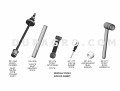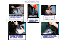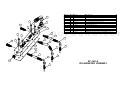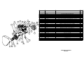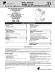
1
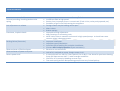
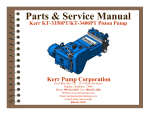
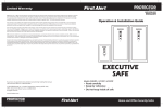
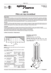
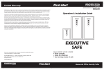
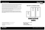
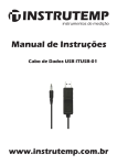
Kerr Pump Corporation
Dupagro
Ooststeeg 102
6708 AX Wageningen
The Netherlands
Phone +31 (0) 317 840 197
Mobile +31 (0) 613 63 55 13
[email protected]
www.dupagro.nl
Dupagro B.V.
Ooststeeg 102
6708 AX Wageningen
The Netherlands
Post Office Box 735 2214 West 14th Street
Sulphur, Oklahoma 73086
Phone: 580-622-4207 Fax: 580-622-4206
Website-www.kerrpumps.com
[email protected]
Phone +31 (0) 317 840 197
[email protected]
United States and Canada
www.dupagro.com
800-441-8149
KERR PUMP CORPORATION SERVICE MANUAL HDD 2 ND EDITION NEW PUMP WARRANTY A. Kerr Machine Company (Kerr Pump Corporation) warrants its new HDD pumps to be free from defective materials and/or workmanship for 1000 HOURS OR ONE (1) YEAR, whichever comes first, from date of sale by distributor, provided that the new pump is registered in accordance with Paragraph No. 2 hereof, properly installed and operated in accordance with the Company’s Service Manual, and all other terms of this warranty agreement are complied with by the purchaser. As hereinafter provided, this warranty includes the replacement of parts and labor to correct any deficiency. All defective parts must be returned to the Company’s Home Office for examination before this warranty is effective. This warranty applies to parts, which have been replaced under this warranty only so long as the original pump warranty is effective. This warranty is for the exclusive benefit of the purchaser and is not transferable. DUPAGRO.COM
B. Each Distributor of a new pump will provide the customer with a registration blank furnished to him by the Company which must state the date of sale, be signed by the purchaser and the Distributor, and delivered to the Home Office of the Company within fifteen (15) days of the date of sale. C. In the event of a claim under this warranty, made within the 1000 HOUR warranty period, the purchaser must notify the Distributor, and the Distributor shall contact Kerr Pump Corporation before any repairs or service calls are made. D. All warranty claims must be sent to Kerr Pump Corporation Home Office on the authorized warranty claim form provided by Kerr Pump Corporation and available from the Distributor before any warranty claim will be considered. It is understood that a pump will deteriorate due to ordinary wear therefore; the following credits shall apply to all replacement parts, labor, surface freight, travel‐time and mileage allowance furnished under this warranty. FOR 1000 HOUR CLAIMS i.
For the first 250 hours, 100% credit will be allowed on a current list price basis. ii.
From 251 hours to 500 hours, 75% credit will be allowed on a current list price basis. iii.
From 501 hours to 750 hours, 50% credit will be allowed on a current list price basis. iv.
From 751 hours to 1000 hours, 25% credit will be allowed on a current list price basis. The credit given to the Distributor for replacement parts or pumps under this warranty is based upon the Distributor’s net cost paid Kerr Pumps for such replacement parts or pumps. E. In the event of a warranty claim under this warranty is made within the first 250 hours, Kerr Pump Corporation, before any repairs begin, shall be contacted by the Distributor and given the option of having the Distributor either repair or replace the pump. F. Upon any claim under this warranty, other than a claim wherein Kerr Pump Corporation at its option replaced the pump as provided in Item ‘E’ hereof, the Distributor will make the necessary repairs and/or replacement, and Kerr Pump Corporation shall allow the cost of labor on warranty claims. The labor cost may include travel time not to exceed (8) hours of actual travel time. Kerr Pump Corporation will pay surface freight on warranty shipments. After making the necessary repairs and/or replacements, the Distributor will bill the customer for the full amount due for the repair. Thereafter, the Distributor will submit the warranty claim form provided by Kerr Pump Corporation to the Kerr Pump Corporation Home Office for consideration. In the event the warranty claim is honored by Kerr Pump Corporation, a Credit Memorandum will be issued to the Distributor in the amount determined by the table in Item ‘D’ hereof. Thereafter, the customer’s invoice will be credited by the Distributor in the same percentage allowed the Distributor by Kerr Pump Corporation. DUPAGRO.COM
If requested by Kerr Pump Corporation the purchaser or the Distributor shall return the alleged defective product to Kerr Pump Corporation factory, freight prepaid, for examination and testing. If Kerr Pump Corporation determines the product is defective, Kerr Pump Corporation will either repair or replace such product with a ‘like’ Kerr Pump Corporation manufacture, f.o.b. to the Distributor or allow the Distributor credit to an amount equal to the invoiced value of the defective product. The responsibility of Kerr Pump Corporation is limited to the repairing or replacing defective material manufactured by it, provided Kerr Pump Corporation examination discloses to its satisfaction that such material has not been altered or repaired, other than by Kerr Pump Corporation approved procedures, subject to misuse, improper maintenance, negligence or accident. Kerr Pump Corporation will not be responsible for loss of liquid or for damage of any kind, or from any cause, to any person or property of any person, or for loss of revenue of profit, or for any other special incidental or consequential damages. G. The warranty applies only to new pumps. The Company specifically excludes from this warranty the following. i.
All pistons, piston rubbers, liners, valves, valve springs, seals gaskets, and corrosion and/or erosion damage caused by the fluid handled by the Company’s pump. ii.
In addition, after the expiration of the pump warranty, all replacement parts are no longer in warranty. H. In extreme cases where in the opinion of Kerr Pump Corporation, if a pump has been misused or is being misused, Kerr Pump Corporation reserves the option to offer to redeem the pump from the purchaser. Should the purchaser refuse to allow the pump to be redeemed and chooses to continue improper operation, the warranty will be void. I. Any parts or equipment which Kerr Pump Corporation supplies and does not manufacture shall be subject only to the warranties of Kerr Pump Corporation vendors to the extent Kerr Pump Corporation can enforce such warranties. J.
K.
DUPAGRO.COM
Any repairs to, alterations of, or work done on alleged defective products without Kerr Pump Corporation specific written authorization shall void Kerr Pump Corporation warranty applicable thereto. Any action for breach of warranty or other action under this agreement must be commenced within (1) year after such cause of action arises. This limited warranty is in lieu of all other warranties, expressed or implied, including any implied warranty or merchantability or fitness. TOUBLESHOOTING Problem Unusual pounding, knocking broken valve spring Loss of pressure or volume Consistent, rhythmic knock •
•
•
•
•
•
•
•
•
Reason/Solution Insufficient fluid at high speed. Suction line is improper size or is constricted. (Trash in line, valve partly opened, etc.) Possibility of gas in the fluid causing the roughness. Foreign matter may be holding valves open. Worn valves. Broken springs. Improper bearing adjustment. Worn bearings or connecting rods. NOTE: Valve noise is common and normal in high‐speed pumps. It should not cause concern unless it becomes erratic. Improper installation. Improper type of lubrication. Incorrect type of packing for particular installation. (Contact Kerr Pump Corporation if you are unsure.) Abrasive or corrosive fluid. Lack of oil, overload on pump, foreign matter in oil. A new pump will run hot for a short period (2 or 3 days). See above for persistent heating. Pump will operate near 140˚ F. under average conditions. Check for air in pump by bleeding at cover caps. Too much spring tension Reciprocating pumps have very limited pick up. DUPAGRO.COM
Packing failure (Excessive) Abnormal wear of fluid end parts Abnormal wear of power end parts Heat in power end •
•
•
•
•
•
•
•
•
INSTALLATION INSTRUCTIONS WARNING Read everything in this section before attempting to run or connect your pump. The importance of proper installation cannot be overstressed. As the reciprocating pump is almost unable to lift fluid, proper suction flooding is a must. This is the First step toward satisfactory operation. For best results, follow these installation guidelines. (A) PRESSURE RELIEF VALVE (REQUIRED) (B) BY‐PASSED FLUID SHOULD BE PIPED BACK IN SUCTION SUPPLY TANK WHEN POSSIBLE (C) (D) (E) (F) USE FLEXIBLE HOSE IN DISCHARGE LINE WHEN POSSIBLE DISCHARGE SHUT‐OFF VALVE (OPTIONAL‐USED FOR TOTAL SHUT‐DOWN OR SERVICE ONLY) DISCHARGE AND SUCTION ON EITHER SIDE OF FLUID END ON ALL MODELS. PULSATION “DAMPENERS” MAY BE USED IN EITHER THE SUCTION OR DISCHARGE PIPING OR BOTH. DISCHARGE DAMPENERS SHOULD BE CAPABLE OF HANDLING PUMP DISCHARGE MAXIMUM PRESSURE DUPAGRO.COM
The Kerr Pumps Engineering Service will be happy to advise you in your installation problems. As almost every installation varies, you cannot exercise too much care in making certain your installation is proper. To start the pump, open the suction line valve and permit the intake chamber to fill on the pump. Air may be bled off by opening the valve covers slightly until there is a constant fluid flow. After bleeding, open the discharge line valve and start the pump. Roughness may occur from cavitations (air in line) or from starvation (lack of fluid). Eliminate these troubles before permitting continuous operation. DUPAGRO.COM
1)
2)
3)
4)
CENTERLINE OF PUMP SUCTION (INLET) TO BE SLIGHTLY
HIGHER THAN CENTERLINE OF SUCTION (INLET) VALVE SO
ANY AIR IN SUCTION SYSTEM PROMPTLY REACHES PUMP
AND IS EXPELLED – A SLOPE OF ¼” PER FOOT IS BEST
SLOPE BYPASS LINE SO LOW POINT DRAIN WILL FULLY
EMPTY RELIEF AND CHOKE VALVES AND ALL LIQUID IN
BYPASS CIRCUIT
DO NOT LOCATE PIPING OR OTHER EQUIPMENT IN FRONT
OF OR ABOVE PUMP FLIUD END PREVENTING SERVICING –
REFER TO MANUFACTURER FOR MINIMUM CLEARANCES
LOCATE CHARGING PUMP AT POINT SHOWN. – IF
CHARGING PUMP IS NECESSARY (FOR VOLATILE FLUIDS,
FOR EXAMPLE)
5)
6)
7)
8)
IF DESIRED, A TWO-WAY MOTOR OPERATED BYPASS VALVE MAY
BE USED RATHER THAN MANUAL TYPE – IT SHOULD BE DESIGNED
TO OPEN AUOMATICALLY WHILE STARTING OR STOPPING
BYPASS LINE SHOULD FEED LIQUID INTO TANK BELOW MINIMUM
LIQUID LEVEL
TO REMOVE PIPING STRAIN AND VIBRATION A FLEXIBLE HOSE,
EXPANSION JOINT OR SWIVEL JOINT PAIR SHOULD BE
POSITIONED TO MINIMIZE EFFECTS OF PIPING THERMAL
EXPANSION, CONTRACTION AND PIPING WEIGHT
SUCTION SIZED FOR 1 ½ TO 2 FT/SEC MAX FLOW RATE.
DISCHARGED SIZED FOR 8 TO 10 FT/SEC MAX FLOW RATE –
SUCTION AND DISCHARGE MUST BE SUPPORTED AND
ANCHORED
9)
TO PROTECT SUCTION SYSTEM AGAINST
HAZARD OF DISCHARGE PRESSURE ENTRY
(AS WHEN PUMP IS IDLE), A SMALL RELIEF
VALVE IS OFTEN CONNECTED HERE
10) ALL SYSTEM COMPONENTS MUST HAVE
ADEQUATE PRESSURE RATINGS FOR
OPERATING, STARTING AND UPSET
CONDITIONS. IN ORDER TO REDUCE
POTENTIAL HAZARDS, PARTICULAR
ATTENTION IS RECOMMENDED FOR THE
SURGE CONDITION THAT WILL RESULT
DOWNSTREAM OF THE REFLIEF VALVE
WHEN NORMAL DISCHARGE IS BLOCKED
-AS A GENERAL RULE, FLUID LEVEL MUST BE HIGHER THAN THE PUMP FLUID END AS PLUNGERS CANNOT LIFT FLUID. 10 FEET OF HEAD IS A GOOD RULE OF THUMB.
-CAUTION SHOULD BE TAKEN TO KEEP FITTINGS OUT OF THE SUCTION AND DISCHARGE PIPING AS THESE WILL RESULT IN POOR PERFORMANCE.
-IF BENDS ARE NECESSARY USE 45° LONG RADIUS ELLS INSTEAD OF 90° ELLS.
PREVENTIVE MAINTENANCE DAILY A. Check and Maintain Lubricant Levels. Standard Lubricant: Synthetic Lubricant: AGMA Grade (ASTM D 2422) ISO Viscosity Grade 4 EP 150 SAE Viscosity Grade (J306‐8) 75W‐90 Viscosity in SSU @ 100 degree F 625‐765 PUMP CAPACITIES (APPROXIMATE) DUPAGRO.COM
KD‐1250 2 qts. KT‐3350 16 qts. KJ‐2250 KZ‐3150 3 qts. KT‐3400 16 qts. 2 qts. Use SAE 30 weight non‐detergent motor oil ONLY KM‐3250 4 qts. KB‐3500 20 qts. KM‐3300 4 qts. KA‐3500 36 qts. KP‐3300 R335/R340 12 qts. 16 qts. KSB‐6400 KSB‐6500 36 qts. 36 qts. Q5450 22.5 gal. KCP‐6300 24 qts. PLANETARY GEAR REDUCERS #6 17 ozs. #8 #9 42 ozs. 42 ozs. B. If pump has lubricating facilities for stuffing boxes, check level of lubricant. C. Maintain packing gland tension on packing (Do not over‐tighten) D. Visually inspect pump for apparent trouble. E. Keep the pump clean. MONTHLY A. Drain and refill crankcase. It is recommended that oil be changed after the first week of operation. B. Wash oil filler cap in kerosene. C. Check valves for excessive wear, broken or bent springs, etc. D. Check crankshaft bearings for endplay. (See section on crankshaft) DUPAGRO.COM
E. Keep all nuts, studs, etc. tight. F. Check valve covers for leaks. G. Check all seals and gaskets for leaks GENERAL Replace any work part before its eventual failure. Use the following instructions for removal and replacement of parts. Don’t hesitate to call on Kerr Pump Corporation for help if necessary at 1‐800‐441‐8149. SERVICE PROCEDURES (ALL MODELS) A. VALVES (Wing‐guided type): i.
DISCHARGE VALVE: The discharge valve and seat can be exposed by first removing the discharge valve cover cap. Once the discharge cover cap has been removed you may lift out the discharge valve spring and the discharge valve. The valve seat will be held in place by a taper fit and must be “pulled” with an appropriate valve‐pulling tool (available from the KERR PUMPS Dealers). Once the valve and seat have been removed they should be resurfaced or replaced if badly worn. To replace the discharge valve, first clean and inspect the seat bore for washout defects and then drop the seat into the bore. Replace the valve into the seat and strike the top of the valve a couple of good blows utilizing a brass bar and hammer to seat the valve seat in the fluid end valve bore. Replace the valve spring and cover cap after inspecting the spring and the seal of the cover cap. ii.
SUCTION VALVE: The suction valves are located in the chamber directly behind the suction or end valve cover caps. The suction valves are serviced in the identical manner as the discharge valves. Note: Discharge valves must be removed prior to any removal of the suction valves. Service Procedure for KZ‐3150PT Valves iii.
DISCHARGE VALVE: The discharge valve and seat can be exposed by first removing the discharge valve cover plate. Once the discharge cover cap has been removed you may lift out the discharge valve spring, discharge valve and valve seat. Once the valve and seat have been removed they should be replaced if badly worn. To replace discharge valve, first clean and inspect the seat bore for wash out defects and then drop the seat into the bore. Replace valve in seat then valve spring and cover cap, always‐
inspecting O‐ring seals between seats and cover caps. DUPAGRO.COM
iv.
SUCTION VALVE: The suction valves are located in the chamber directly below the discharge valve seat. The suction valves are serviced in the identical manner as the discharge valves. B. PONY ROD and PONY ROD PACKING: Pumps use two pony rod sealing arrangements, models KM‐3250PT and KM‐3300PT use a screw in seal gland, all other models use a bolt in seal gland, these glands use press in oil seals with snap ring retainers. Some bolt in gland use adjustable packing arrangements with bolt in or screw in followers to adjust packing. By unscrewing plunger from pony rod a gap may be facilitated to allow the removal of the various sealing arrangements. A special wrench will be needed to remove and replace pony rod to crosshead. (This wrench is available from Kerr Dealers) All pony rods have a jam nut to align tighten pony rod to crosshead, care must be exercised in installing new seal on pony rod not to damage it. C. DISASSEMBLY OF POWER END. CAUTION: Prior to disassembly of any power end, the plunger, pony rod, and pony rod seal housing must be removed. Expose the crankshaft and connecting rods by removing the pan cover. Connecting rod caps may now be removed and the connecting rod and crosshead should be shoved all the way to the rear (toward the fluid end) to facilitate crankshaft removal out either side as convenient. The connecting rods and crossheads may now be taken out the front cavity exposed by removing the crankshaft. Connecting rods may be removed from the crosshead by loosening the setscrew and driving out the wrist pin from the crosshead. A bronze bushing is used in the rod it may be driven out of the rod and replaced with a new bushing. Reassembly is the reverse of the above outlined sequence with the following considerations for “fits” or tolerance: i.
General: All Kerr components are machined on modern production machine tools and are of the same specifications and close tolerances you would expect in a modern automobile engine. It must be pointed out that at top speed (350 to 400 RPM) your pump will not even be approaching idle speed for a gasoline engine so “field fits” are possible and practical when making repairs and replacements away from the factory. All procedures outlined below are possible with only hand tools and absolutely no instruments, special tools, or gauges are needed. ii.
Connecting rod and wrist pin: Proper fit will find the wrist pin turning freely in its bore in the connecting rod, but it should have no “wobble” that is discernable up and down the main axis of the connecting rod. This looseness in the wrist pin fit is the most probable cause of “knocking” which is traceable to the power end of most all pumps. The only solution for loose fitting wrist pins is to discard the connecting rod wrist pin bushing and replace with a new one. If any wear is visible on the wrist pin it should always be replaced. DUPAGRO.COM
iii.
Crankshaft End Play and Lateral adjustments: Adjustment of the Taper Roller bearings used in all Kerr Pumps is accomplished by removing or adding shims under the bearing housing. Shims are taken out or added until the crankshaft (without connecting rods) will turn freely, but with no endplay felt when attempting to pull or push the jackshaft end of the crankshaft along its long axis. Some lateral adjustment is possible by removing shims from one side of the crankshaft and adding them to the opposite side. (Note: Lateral adjustment is the “centering” of the crankshaft in the power frame housing.) iv.
Connecting Rod to Crankshaft fitting: Factory bored connecting rods will normally fit the standard crankshaft journal just by bolting the cap on the rod with the standard rod shims being used. If the caps do require adjustment this is accomplished by removing or adding various thicknesses of rod shims. The standard connecting rod shim used on all Kerr Pumps is 1/32” thick and is comprised of .002” laminates, which can be “pealed “ off separately. Proper fit of the connecting rod will allow the pump crankshaft to be rotated while not allowing in‐and‐out slack in the connecting rod along its long or main axis. A well‐fitted rod will have none of the in‐and‐out slack, but should be free enough to be moved from side to side on the rod journal. This insures the rod not being too tight. A point of caution when installing the connecting rod assembly in the pump is to make certain the oil holes in the rod are “UP” and not toward the bottom of the pump. This will result in lubrication failure in these parts and the pump will fail in a short period of time. An additionally important step is to make sure that the rod cap is bolted back on the rod as it came off. The rod and cap carry a “mark” or “number” which allows you to match them back properly. Failure to do this will cause the rod not to fit the journal for which it was made. D. Power End/Fluid End Connection: A common misconception is that there is some form of fluid seal between the power end and the fluid end. This is false. The fluid end is merely bolted to the power frame. To take off the Fluid End all the Liners must be removed by unthreading all retainer Nuts from each retainer Stud, sliding off each liner Retainer, followed by any unscrewing all other power frame to fluid end cap screws, removing the Piston Rod Clamp, then safely sliding the Fluid End away from the Power Frame. DUPAGRO.COM
TECHNICAL DATA SHEET PCN: ______ T.D.S. NO. Supercedes PCN: _____ Date 4.2 03‐10‐06 SHORT TERM STORAGE PREPARATION PROCEDURE 1.0 SCOPE This procedure applies to Kerr Pumps ONLY. Storage procedures for any other unit components or accessories (gear reducers, engines, etc.) are to be prepared to the specific manufacture’s recommendations. 1.1 Short‐term storage is defined as storage and/or transient time less than six (6) months in an environment defined in Paragraph 2. If storage exceeding six months is expected, the Long Term Pump Storage Preparation Procedure should be followed. 1.2 Kerr Pumps will only prepared for short term storage if so specified in the purchaser or customer order control document. 2.0 STORAGE ENVIRONMENT DUPAGRO.COM
A minimal environmental condition, to be met by the customer or purchaser, is a closed shelter to eliminate effects of sun, wind, sand or other debris. Large temperature and humidity changes should be avoided to prevent coating deterioration or contamination by moisture. 3.0 PRESERVATIVE PRODUCT 3.1 The specified rust preservative will protect the internal power end parts from corrosion due to atmospheric moisture, and may be left in the pump when filled with appropriate lubricant and placed into service. The elevated temperature of service will cause rapid depletion of the preventative protection. The following rust preventative products or their equivalents are recommended for use in Kerr Pumps and usually available in 5 gallon, 55 gallon containers: 3.2 CITGO: RUST‐O‐LINE OIL 10 SHELL: ENSIS OIL N 4.0 PROCEDURE 4.1 Preparation from; factory testing, inventory, or a distributor rebuild facility. ‐ Drain any oil that may be in the power end, and then fill the complete power end cavity with the specified rust preventative. After 15 to 20 minutes, drain the rust preventative back into its storage drum for future use. ‐ Remove and clean oil level gages, pressure gages and breather caps. Replace with pipe plugs in threaded openings. All breathers shall be replaced with airtight seals, plugs or gasketed plates. No venting is recommended as it may allow moist air in. TECHNICAL DATA SHEET PCN: ______ T.D.S. NO. Supercedes PCN: _____ Date 4.2 03‐10‐06 4.1.1
Remove the wiper box seals and cap/plug the seal opening. 4.1.2
Clean the pump outer surfaces prior to painting. 4.1.3
If painting is required mask crank and lubricator shaft surfaces and keyways. If painting does not apply, go to Para. 4.1.8. 4.1.4
Paint as specified by the customer order or as required. 4.1.5
Apply a thin layer of grease to the exposed oil seal lips. 4.1.6
Apply a thin layer of heavy rust preventative to the exposed crank and lubricator shaft surfaces and keyways. 4.1.7
Wrap the exposed crank and lubricator shafts with waxed tape. 4.1.8
Carefully wrap the following parts prior to placing them into polyurethane bags. Oil level gages, lube pressure gages, and breather caps. 4.1.9
Finish box, crate and mark the parts from Para. 4.1.2 after final inspection (see Para. 4.2.2). 4.2 Shipping/Receiving (New Pumps Only) 4.2.1 All pumps and accessories (as applicable) will be final inspected by Kerr Pump personnel prior to shipping. Any witnessed or third party inspection will be signed‐off by the purchaser or customer representative prior to final crating and shipment. 4.2.2 Export crating will be performed by either an approved Kerr Pump source or as specified by the purchaser or customer. Any third party inspection will be coordinated with the source. 4.2.3 Upon receipt of the shipment, the purchaser or customer is responsible for inspection and repair of damaged coatings at the expense of the shipper. DUPAGRO.COM
5.0 WARRANTY/START‐UP 5.1 5.2 5.3 Pumps prepared per the above procedure qualify for the “Standard Terms & Conditions” in force on the date of shipment. If the pump storage period is less than 6 months, follow the Short Term Pump Preparation Procedure. Prior to start‐up: 5.3.1
5.3.2
5.3.3
5.3.4
5.3.5
5.3.6
5.3.7
Remove all storage caps, plugs, and covers. Replace any damaged or cracked O‐rings or gaskets. Inspect power end shaft oil seals and replace if cracked, split or damaged. Install crankcase drain plug, lubrication level site glass and breather cap. Install, if applicable, any oil pressure and/or temperature gage. Check the connection of the plunger and pony rod to the crosshead prior to, and after, initial run‐in of the pump. Fill the crankcase to the proper level with the specified lubricant. TECHNICAL DATA SHEET PCN: ______ T.D.S. NO. Supercedes PCN: _____ Date 4.3 03‐10‐06 TITLE: LONG TERM STORAGE PREPARATION PROCEDURE 1.0 SCOPE This procedure applies to Kerr Pumps ONLY. Storage procedures for any other unit components or accessories (gear reducers, engines, etc.) are to be prepared to the specific manufacture’s recommendations. 1.1 Long‐term storage is defined as storage and/or transient time exceeding six (6) months in an environment defined in Paragraph 2. If storage for less than six months is expected, the Short Term Pump Storage Preparation Procedure should be followed. 1.2 Kerr Pumps will only prepare for short term storage if so specified in the purchaser or customer order control document. 2.0 STORAGE ENVIRONMENT DUPAGRO.COM
A minimal environmental condition, to be met by the customer or purchaser, is a closed shelter to eliminate effects of sun, wind, sand or other debris. Large temperature and humidity changes should be avoided to prevent preventative deterioration or contamination by moisture. 3.0 RUST PREVENTATIVE PRODUCT 3.1 The recommended rust preservative should protect the internal power end parts from corrosion due to atmospheric moisture, and may be left in the pump when filled with appropriate lubricant and placed into service. The elevated temperature of service will cause rapid depletion of the preventative protection. 3.2 The following rust preventative products or their equivalents are recommended for use in Kerr Pumps and usually available in 5 gallon, 55 gallon containers: CITGO: RUST‐O‐LINE OIL 10 SHELL: ENSIS OIL N 4.0 PROCEDURE 4.1 Preparation from; factory testing, inventory, or a distributor rebuild facility. 4.1.1 Drain any oil that may be in the power end and then fill the complete power end cavity with the specified rust preventative. After 15 to 20 minutes, drain the rust preventative back into its storage drum for future use. 4.1.2 Remove all plungers, pony rods (if applicable), baffle discs, packing and junk rings. 4.1.3 Remove and clean oil level gages, pressure gages and breather caps. Replace with pipe plugs in threaded openings. TECHNICAL DATA SHEET PCN: ______ 4.1.4 4.1.5 4.1.6 4.1.7 4.1.8 4.1.9 4.1.10 4.1.11 4.1.12 4.1.13 4.2 4.2.3 Supercedes PCN: _____ T.D.S. NO. Date 4.3 03‐10‐06 All breathers shall be replaced with airtight seals, plugs or gasketed plates. No venting is recommended as it may allow moist air in. Remove the wiper box seals and cap/plug the seal opening. Clean the pump outer surfaces prior to painting. If painting is required mask crank and lubricator shaft surfaces and keyways. If painting does not apply, go to Para. 4.1.9. Paint as specified by the customer order or as required. Apply a thin layer of grease to the exposed oil seal lips. Apply a thin layer of heavy rust preventative to the exposed crank and lubricator shaft surfaces and keyways. Wrap the exposed crank and lubricator shafts with waxed tape. Carefully wrap the following parts prior to placing them into polyurethane bags. Oil level gages, lube pressure gages, and breather caps. Finish box, crate and mark the parts from Para. 4.1.10 after final inspection (see Para. 4.2.2). All pumps and accessories (as applicable) will be final inspected by Kerr Pump personnel prior to shipping. Any witnessed or third party inspection will be signed‐off by the purchaser or customer representative prior to final crating and shipment. Export crating will be performed by either an approved Kerr Pump source or as specified by the purchaser or customer. Any third party inspection will be coordinated with the source. Upon receipt of the shipment, the purchaser or customer is responsible for inspection and repair of damaged coatings at the expense of the shipper. WARRANTY / START‐UP 5.1 5.2 5.3 DUPAGRO.COM
4.2.2 5.0 Shipping/Receiving (New Pumps Only) 4.2.1 Pumps prepared per the above procedure qualify for the “Standard Terms & Conditions” in force on the date of shipment. If the pump storage period will exceed 6 months, follow the Long‐Term Pump Preparation Procedure. Prior to start‐up: 5.3.1 Remove all storage caps, plugs, and covers. 5.3.2 Install packing, junk rings, plungers, pony rods (if applicable), baffle discs, and wiper box seals. Replace any damaged or cracked O‐rings or gaskets. 5.3.3 Inspect power end shaft oil seals and replace if cracked, split or damaged. 5.3.4 Install crankcase drain plug, lubrication level site glass and breather cap. 5.3.5 Install, if applicable, any oil pressure and/or temperature gage. 5.3.6 Check the connection of the plunger and pony rod to the crosshead prior to, and after, initial run‐in of the pump. 5.3.7 Fill the crankcase to the proper level with the specified lubricant. Daily
Weekly
Monthly
Quarterly
Semi-Annual
Yearly
or 8 Hrs
or 40 Hrs
or 200 Hrs
or 500 Hrs
or 1000 Hrs
or 2000 Hrs
Check Oil Level in Pump
Visual Inspection
Visual Inspection
Service
Check Oil Level in Planetary
Gear
Visual Inspection
Visual Inspection
Service
Check for Water or Bentonite
in Gear Box
Visual Inspection
Visual Inspection
Visual Inspection
Visual Inspection
Visual Inspection
Visual Inspection
Check Piston Chamber for
Leaking Pistons
Visual Inspection
Visual Inspection
Visual Inspection
Visual Inspection
Visual Inspection
Visual Inspection
Check Recovery Tank for
Bentonite
Visual Inspection
Visual Inspection
Service
Check Piston Cooling Pump
for Proper Operation
Visual Inspection
Visual Inspection
Visual Inspection
Visual Inspection
Visual Inspection
Visual Inspection
Kerr Pump Maintenance
Schedule for
Piston Type Pumps
DUPAGRO.COM
Service
Service
Service
Service
Service
Visual Inspection
Visual Inspection
Visual Inspection
Visual Inspection
Service
Check and Replace if
Necessary Piston Cups
Visual Inspection
Visual Inspection
Visual Inspection
Service
Check and Replace if
Necessary Valve Inserts
Visual Inspection
Visual Inspection
Visual Inspection
Service
Check and Replace if
Necessary Valves and Seats
Visual Inspection
Visual Inspection
Visual Inspection
Service
Check and Replace if
Necessary Liners
Visual Inspection
Visual Inspection
Visual Inspection
Service
Visual Inspection
Visual Inspection
Visual Inspection
Service
Flush Fluid End
Check Pony Rod Seals
Check Rod Bearings
Service
Check Pony Rods
Visual Inspection
Visual Inspection
Visual Inspection
Visual Inspection
Visual Inspection
Visual Inspection
Check Belts
Visual Inspection
Visual Inspection
Visual Inspection
Visual Inspection
Visual Inspection
Service
DUPAGRO.COM
KP-76M
WINGGUIDED
SEAT
TRI-PIN
TYPE
PULLER
ASS'Y
KA-306
VALVE
SEAT
SEATING
TOOL
KP-276
PONY
ROD SEAL
TOOL
AP-77T
VALVE
INSERT
TOOL
SPECIAL TOOLS
FOR KP-3300PT
KP-21S
ALIGNMENT
SEAL
SLEEVE
KP-277
PONY
ROD
WRENCH
How To Put Inserts In Valves
Using Kerr Valve Insert Tool
1) Push Valve Insert over
valve legs. Hint: (Insert
will be more pliable if
heated first-- warm to the
touch not hot).
2) Put Tool between
valve and valve
insert with groove
against valve.
3) Holding Valve
insert down with
thumb.
DUPAGRO.COM
4) While holding valve down
with thumb, rotate around
valve with tool. (Similar to
mounting a tire on a rim).
5) Continue rotating around
valve with tool until insert is
completely in groove.
ITEM NO. QTY. PART NO.
1
1 KP-160
2
1 KP-161
3
3 KP-160-5
4
3 KP-160-6
5
2 KP-160-7
6
1 KP-160-8
7
1 AP-160-1
8
1 AP-160-2
9
4 AP-190-3
10
5 AP-160-3
11
4 AP-190-13
12
1 AP-160-4
8
9
7
9
10
11
11
9
1
DESCRIPTION
OIL MANIFOLD
OIL MANIFOLD GASKET
FITTING CROSSHEAD OIL INJECTOR
SAE 37 JIC FML SWIVEL 90 DEG TUBE ELBOW 1/4 X 1/4
3 1/4" (450 DEG) SS TEFLON HOSE
4 1/4" (450 DEG) SS TEFLON HOSE
JIC MALE ELBOW 1/2
SAE 37 JIC FML SWIVEL 90 TUBE ELBOW 1/4 X 1/2
WATER MANIFOLD / OIL MANIFOLD BOLT
MALE PIPE RIGID 1/4 X 1/8
1/4 LOCK WASHER
1/2-NPT PIPE PLUG SOCKET TYPE INTERNAL HEX
DUPAGRO.COM
10
9
5
4
10
10
11
6
11
3
4
2
10
5
3
4
12
3
KP-160-A
OIL MANIFOLD ASSEMBLY
ITEM NO.
7
8
12
7
27
6
5
11
28
27
7
25
19
13
4
2
16
33
23
20
29
18
KP-235
KP-140
KP-130
AP-190-13
KP-155
KP-205
AP-160-1
AP-160-2
KP-7
AP-195
AP-145
AP-150
AP-200-320
AP-230
AP-230-9
AP-135
AP-130-9-1
KA-6
KA-6B
KA-230-15
KA-230-16
AP-235-17
AP-235-19
AP-235-22
AP-235-23
AP-235-24
AP-235-27
AP-235-30
AP-235-31
AP-235-32
AP-190-14
AP-235-21
AP-132
DESCRIPTION
BELT GUARD, PUMP DRIVE
OIL AND WATER PUMP BRACKET
BEARING HOUSING, EXTENSION SHAFT SIDE
1/4 LOCK WASHER
BELT, OIL PUMP
BELT, WATER PUMP
JIC MALE ELBOW 1/2
SAE 37 JIC FML SWIVEL 90 TUBE ELBOW 1/4 X 1/2
BEARING HOUSING GASKET
WATER PUMP, BRONZE
OIL PUMP, 1/2" CAST IRON
SHEAVE, OIL PUMP
SHEAVE, WATER PUMP
SHEAVE, CRANKSHAFT DRIVE TO PUMPS
SHEAVE BUSHING 1-1/8"
OIL SEAL, BEARING HOUSING EXTENSION SHAFT
KEY- SUPPLIED WITH KA-KP-KT-230-9
BEARING HOUSING CAPSCREW (1 1/2)
BEARING HOUSING CAPSCREWS (2")
BOLT SUPPLIED WITH AP-230-9
WASHER SUPPLIED WITH AP-230-9
1/4-20UNC X 1 1/4 CAPSCREW
1/4 WASHER
3/8 WASHER
3/8 LOCK WASHER
3/8-16-UNC HEX HEAD NUT
3/8-16UNC X 3/8 SETSCREW
SAE 37 JIC FML SWIVEL 3/8 X 1/2
SAE JIC MALE CONNECTOR 1/4 X 1/8
SAE 37 JIC FML SWIVEL 90 DEG TUBE ELBOW 1/4 X 1/4
1/4-20UNC NUT
3/8-16UNC X 1 1/4
AUXILIARY SHAFT-SUPPLIED WITH KP-120
EXPLO
DED/Q
TY.
1
1
1
2
1
1
3
1
1
1
1
1
1
1
1
1
1
3
3
3
3
2
2
2
2
2
2
2
1
1
2
2
1
DUPAGRO.COM
22
24
14
9
3
31
15
1
30
10
26
21
28
1
2
3
4
5
6
7
8
9
10
11
12
13
14
15
16
17
18
19
20
21
22
23
24
25
26
27
28
29
30
31
32
33
PART NUMBER
32
17
PUMP DRIVE ASSEMBLY
KP-235-A
DUPAGRO.COM
REV B: 05-09-00 ADDED ITEMS 15 & 16;
REV C: 05-25-06 UPDATED PART NUMBERS;
3
3
3
8
3
4
10
5
16
1
8
7
2
15
6
10
13
14
13
14
11
13
9
14
13
14
12
9
11
12
12
ITEM NO.
1
2
3
4
5
6
7
8
9
10
11
12
13
14
15
16
PART NUMBER
KP-210
AP-190-2
AP-190-3
AP-190-4
AP-190-5
KP-192
KP-190
AP-190-8
AP-190-9
AP-190-10
AP-190-11
KA-190-12
AP-190-13
AP-190-14
KP-191
AP-216
DESCRIPTION
WATER MANIFOLD
WATER MANIFOLD PLUG
WATER MANIFOLD / OIL MANIFOLD BOLT
WATER MANIFOLD 90 DEGREE FITTING
3/8 QUICK COUPLING
PISTON CHAMBER COVER SIGHT GLASS
PISTON CHAMBER COVER
PISTON CHAMBER COVER INPECTION GLASS WING NUT
PISTON CHAMBER COVER INSPECTION GLASS CAPSCREW
PISTON CHAMBER COVER WING NUT
PISTON CHAMBER COVER CAPSCREW
FITTING WATER JET
1/4 LOCK WASHER
1/4-20UNC NUT
PISTON CHAMBER COVER GASKET
3/8" QUICK CONNECT
WATER MANIFOLD ASSEMBLY
(EXPLODED VIEW)
KP-190-A
QTY.
1
1
4
1
1
1
1
2
2
2
2
3
4
4
1
1
8
D
7
ITEM NO. QTY. PART NO.
1
1 KP-250-250
2
1 KT-263-250
3
1 KA-246
4
1 KP-251-250
KP-245-250
PISTON COMPLETE
6
5
4
3
2
1
ITEM NO. QTY. PART NO.
DESCRIPTION
1
1 KP-285-250CH LINER, 2.5" HEAT TREATED
2
1 KP-265
PISTON EXTENSION ROD
3
1 KA-270
PISTON EXTENSION ROD LOCK NUT
4
1 KP-290-300 LINER RETAINER
5
1 KP-245-250 PISTON COMPLETE 2 1/2"
6
1 KP-280
CLAMP, PONY ROD TO PISTON ROD
7
1 KP-275
PONY ROD, PISTON PUMP TYPE
8
1 KP-295
LINER GASKET
DESCRIPTION
PISTON, BODY ONLY 2 1/2"
PISTON CUP 2 1/2"
PISTON O-RING
PISTON CUP RETAINER 2 1/2"
4
2
D
REV B: 05-25-06
UPDATED PART NUMBERS;
DUPAGRO.COM
1
3
C
C
8
1
B
B
3
4
5
2
6
7
KERR MACHINE CO BOX 735 SULPHUR OK 73086
PHONE (580) 622-4207 FAX (580) 622-4206
WARNING:
CONFIDENTIAL AND PROPRIETARY
INFORMATION OF "Kerr Pumps" DO
NOT DISCLOSE, COPY OR REPRODUCE
A
UNLESS OTHERWISE SPECIFIED
TOLERANCES
ANY OR PART OF THIS PRINT WITHOUT
PRIOR WRITTEN APPROVAL FROM
KERR MACHINE CORPORTATION.
MACHINE
.X
=
.XX
=
.XXX =
.XXXX =
ANGLES
8
7
6
5
4
1. MATL:
2. DIMS. ARE IN INCHES
3. DIM MAY VARY
ACCORDING TO CASTING
4. REMOVE ALL BURRS AND
SHARP CORNERS
5. DO NOT SCALE DRAWING
± .030
± .010
± .005
± .0010 6. MACHINE FINISH
± 1/2º
3
63
DESIGNED BY:
B MILNER
04-23-99
DRAWN BY:
K LACKEY
04-14-00
REFERENCE:
_
PUMP:
KP-3300-PT
THIRD ANGLE PROJECTION
Kerr
Pumps
TITLE
SIZE
2
A
PISTON ASSEMBLY
DRAWING
DWG. NO.
D
SCALE:
SULPHUR OK
FULL
KP-245-250-A
WEIGHT: _
SHEET 1
1
REV
B
OF
1
ITEM NO. QTY. PART NO.
1
1 KP-250-275RD
2
1 KP-263-275RD
3
1 KP-261-275RD
4
1 KP-264RD
5
1 KP-246RD
ITEM NO. QTY. PART NO.
1
1 KP-285-275CH
2
1 KP-265RD
3
1 KP-270RD
4
1 KP-290-300
5
1 KP-245-275RD
6
1 KP-280
7
1 KP-275
8
1 KP-295
DESCRIPTION
PISTON BODY ONLY 2 3/4" (RUN DRY TYPE)
PISTON CUP 2 3/4" (RUN DRY TYPE)
PISTON CUP RETAINER PLATE (RUN DRY TYPE)
PISTON CUP NUT (RUN DRY TYPE)
PISTON O'RING (RUN DRY TYPE)
DESCRIPTION
LINER 2 3/4" CHROME
PISTON EXTENSION ROD (RUN DRY TYPE)
PISTON EXTENSION ROD NUT (RUN DRY TYPE)
LINER RETAINER
PISTON COMPLETE 2 3/4" (RUN DRY TYPE)
CLAMP, PONY ROD TO PISTON ROD
PONY ROD, PISTON PUMP TYPE
LINER GASKET
KP-245-275RD
PISTON COMPLETE
4
3
8
2
5
1
1
3
2
5
4
7
6
A
6
7
PISTON ASSEMBLY
DRAWING
KP-245-275RD-A
DUPAGRO.COM
A
SECTION A-A
SCALE 1 : 2
2
5
4
1
3
8
ITEM NO. QTY. PART NO.
1
1 KP-250-300
2
1 KP-263-300
3
1 KP-261-300
4
1 KP-262-350
5
1 KA-246
DUPAGRO.COM
DESCRIPTION
PISTON, BODY ONLY, 3"
PISTON CUP 3"
PISTON CUP RETAINER PLATE
PISTON CUP SNAP RING
PISTON O-RING
ITEM NO. QTY. PART NO.
1
1 KP-285-300
2
1 KP-265
3
1 KA-270
4
1 KP-290-300
5
1 KP-245-300
6
1 KP-280
7
1 KP-275
8
1 KP-295
KP-245-300
PISTON COMPLETE
*ITEMS 2,3,4 SOLD AS A SET ONLY
PART #KP-260-300
DESCRIPTION
LINER 3"
PISTON EXTENSION ROD
PISTON EXTENSION ROD LOCK NUT
LINER RETAINER
PISTON COMPLETE 3"
CLAMP, PONY ROD TO PISTON ROD
PONY ROD, PISTON PUMP TYPE
LINER GASKET
Dupagro
1
4
3
2
5
B
6
7
PISTON ASSEMBLY
DRAWING
KP-245-300-A
B
SECTION B-B
SCALE 1 : 2
8
12
6
9
5
4
3
8
ITEM NO.
1
2
3
4
5
6
7
8
9
10
11
12
QTY. PART NO.
1 KP-29BCD
3 KP-81HT
6 KP-85
3 KP-80HT
3 KT-52L
3 KP-30BC
3KT-52S
6 KP-82HT
6 KP-32
3 KP-31BC
1 AP-71
24 KP-35
DESCRIPTION
FLUID END
SUCTION VALVE A/R
ABRASIVE RESISTANT VALVE INSERT
DISCHARGE VALVE A/R
VALVE SPRING (DISCHARGE) (LONG)
TOP COVER CAP
VALVE SPRING (SUCTION) (SHORT)
SEAT ABRASIVE RESISTANT SS
COVER CAP "O" RING
END COVER CAP
FLUID END DRAIN PLUG
COVER CAP CAPSCREW
DUPAGRO.COM
7
2
3
8
9
12
10
11
KP-29BC
DUPAGRO.COM
KP-3300PT
DUPAGRO.COM
KP-3300PT WITH DRIVE ASSEMBLY
2
KP-3300PT PISTON TYPE TORQUE SPECIFICATIONS
8
1
7
11
9
DUPAGRO.COM
10
3
4
5
6
WHEN ADJUSTING THE ENDPLAY
OF THE TAPERED ROLLER BEARINGS
USED ON THE CRANKSHAFT,
DIAL INDICATORS AND SHIMS MUST
BE PROPERLY USED. INCORRECT
BEARING ADJUSTMENT MAY RESULT
IN EXCESSIVE NOISE, TEMPERATURE, AND
REDUCED BEARING LIFE. Kerr Pumps
RECOMMENDS BETWEEN .000” - .005”
OF INTERNAL AXIAL CLEARANCE
(END PLAY) WHEN ASSEMBLED. FINAL
ADJUSTMENT MUST BE MADE USING A
DIAL INDICATOR.
.000" - .005"
SHAFT END PLAY
INSURE THE CONNECTING RODS ARE
DISCONNECTED TO ALLOW FREE
CRANKSHAFT MOTION.
TORQUE
DESCRIPTION
REFERENCE
21 ft-lb (28 Nm)
PAN COVER CAPSCREW
125 ft-lb (169 Nm)
CONNECTING ROD CAPSCREW
75 ft-lb (102 Nm)
BEARING HOUSING CAPSCREW
30 ft-lb (41 Nm)
WRIST PIN SET SCREW AND JAM NUT
500 ft-lb (678 Nm)
PONY ROD
50 ft-lb (68 Nm)
PONY ROD PACKING GLAND CAPSCREWS
120 ft-lb (163 Nm)
FLUID END STUD NUT
20 ft-lb (27 Nm)
CLAMP SOCKET HEAD CAPSCREW
245 ft-lb (332 Nm)
COVER CAP CAPSCREWS
PISTON LINER RETAINER STUD NUT
100 ft-lb (136 Nm)
PISTON EXTENSION ROD SELF-LOCKING NUT 500 ft-lb (678 Nm)
1
2
3
4
5
6
7
8
9
10
11
NOTE: WHEN USING LUBRICANTS,
REDUCE TORQUE AS FOLLOWS:
LU B R IC A N T
W H ITE L E A D
G R A P H IT E
O IL
G R EA SE
A N TI - SE IZE C O M P O U N D
P E R C E N TA G E O F T O R Q U E R E D U C TIO N R E Q U IR E D
R ED UC E
R ED UC E
R ED UC E
R ED UC E
R ED UC E
TO R Q U E
TO R Q U E
TO R Q U E
TO R Q U E
TO R Q U E
25%
30%
40%
40%
45%
2"-NPT
8.3
15.7
2.0
7.125
13.5
14.25
28.5
12.0
4.25
39.35
4X 9/16
MOUNT
HOLES
DUPAGRO.COM
27.125
19.0
2"-NPT
1/4"-NPT
8.875
19.876
6.375
.75
4.55
10.125
5.625
5.062
2"-NPT
DISCHARGE
4.125
8.0
2.25
3"-NPT
SUCTION
GENERAL DIMENSIONS FOR KP-3300PT
2"-NPT
7.2
2.0
15.7
13.50
28.5
12.00
4.25
4X 9/16
MOUNT
HOLES
DUPAGRO.COM
27.125
28.25
1/4"-NPT
19.0
2"-NPT
2"-NPT
DISCHARGE
14.66
7.33
8.875
19.9
14.0
8.00
4.25
20
6.375 4.55
.75
10.125
5.625
5.062
39.3
2.63
3"-NPT
SUCTION
GENERAL DIMENSIONS FOR KP-3300PTHD
AP-195
KP-200
KP-205
KP-160
AP-16
KP-215
KP-290
KP-30D
KP-32
KP-250RD
KP-210
KP-29D
KP-11
KP-10
KP-32
KP-31D
KT-52L
LONG SPRING
KP-80HT
DISCHARGE
VALVE
KP-85
INSERT
KP-82HT
VALVE SEAT
KP-165
KP-235
BACK PLATE REMOVED
TO SHOW BELTS
AP-145
KP-155
KP-175
KP-18
AP-72
KP-170
KP-12
DUPAGRO.COM
KP-300
DISCHARGE
VALVE ASSEMBLY
KT-52S
SHORT
SPRING
KP-81HT
SUCTION
VALVE
KP-85
INSERT
KP-85
INSERT
KP-305
SUCTION
VALVE ASSEMBLY
KA-30
KP-285
KP-260RD
KP-265RD
KP-28
KP-15
KP-15A
KP-14
KP-280
KP-295
*REMOVE PISTON & LINER
AS AN ASSEMBLY IN
ORDER TO SERVICE
KP-285
KP-245RD
KP-3300PT
KP-20
KP-121
KP-1PT
KP-25-000
TROUBLESHOOTING GUIDE
KP-17A
for K err
P um p
THREE SEALS TO
FOR LEAKING PISTONS
CRANKCASE OIL 1) -CHECK
REPLACE IF NECESSARY
KP-24
KP-22
PONY ROD
GLAND
KP-22S
GASKET
KP-265RD SNAP
KP-22G
RING
KP-22-A
PONY ROD
PACKING GLAND
ASSEMBLY
2) CHECK FOR PROPER FLUID FLOW
TO PUMP
- MINIMUM REQUIREMENTS 3"
SUCTION HOSE NO MORE THAN 50'
LONG WITH 30 PSI OF CONTINUOUS
PRESSURE FEEDING PUMP
3) REMOVE VALVE COVER CAPS AND
INSPECT VALVES & VALVE SEATS
FOR FOREIGN OBJECTS AND WEAR
- REPLACE IF NECESSARY
AP-195 KP-215
AP-200-320
KP-235
KP-64
KP-35
KP-31BCD
KP-32
KP-205
AP-16T
KP-191
KP-190
KP-290
KP-65S
KP-160
KP-165 KP-155
AP-145
KP-175
KP-140
KP-20
KP-12
KP-10
KP-14T
KP-11
KP-170
KP-18
KP-35
KP-64
AP-72
KP-31BCD
KP-32
DUPAGRO.COM
KP-29BC
KT-52L
LONG SPRING
KP-80HT
SUCTION VALVE
KP-85
INSERT
KP-82HT
VALVE SEAT
C
AP-71
KA-30
KP-15
KP-15A
KP-265
KP-280
KP-270
EXTENSION ROD
LOCK NUT
KP-265
PISTON
EXTENSION
ROD
KP-17A
KP-25-000
KP-280
CLAMP
KP-305HT
SUCTION
VALVE ASSEMBLY
THREE SEALS TO
CRANKCASE OIL
KP-24
KP-275
PONY ROD
KP-22
KP-22G
KP-22-A
KP-22S
PONY ROD
PACKING GLAND
ASSEMBLY
KP-300HT
DISCHARGE
VALVE ASSEMBLY
KT-52S
SHORT SPRING
KP-81HT
DISCHARGE
VALVE
KP-85
INSERT
KP-82HT
VALVE SEAT
KP-1
KP-295
LINER
GASKET
KP-285
LINER
TROUBLESHOOTING GUIDE
for Kerr
Pump
KP-65
KP-245
KP-65S
PISTON
COMPLETE
*REMOVE PISTON & LINER
AS AN ASSEMBLY IN
DETAIL C
ORDER TO SERVICE
SCALE 1 : 3
KP-3300PT
1) CHECK FOR LEAKING PISTONS
- REPLACE IF NECESSARY
2) CHECK FOR PROPER FLUID FLOW
TO PUMP
- MINIMUM REQUIREMENTS 3"
SUCTION HOSE NO MORE THAN 50'
LONG WITH 30 PSI OF CONTINUOUS
PRESSURE FEEDING PUMP
3) REMOVE VALVE COVER CAPS AND
INSPECT VALVES & VALVE SEATS
FOR FOREIGN OBJECTS AND WEAR
- REPLACE IF NECESSARY
Kerr KP-3300PT Piston Type Pump
Part Number
KP-1PT
KP-2
KP-2S
KP-3
KP-3S-8
KA-6
KA-6B
KP-6HD-125-6
KP-6HD-125-6000
KP-7
KP-8-005
KP-8-010
KP-8-015
KP-9
KP-9S
KP-10
KP-11
KP-12
KP-14T
KP-15
KP-15A
AP-16
AP-16T
KP-16
KP-17
KP-17
KP-17A
KP-17
KP-18
KP-20
KP-22
KP-22A
KP-22G
KP-22S
KP-22M
Description
Pump Case
Crankshaft - Heat Treated
Crankshaft - (Steel)
Crankshaft Oil Seal
Crankshaft Oil Seal For Crankshaft 120S-8
Bearing Housing Capscrews
Bearing Housing Capscrews 2
Socket Head Capscrew for Bearing Housing Hyd-125-6
Socket Head Capscrew for Bearing Housing Hyd-125-6000
Bearing Housing Gaskets
Main Bearing Adjusting Shims .005
Main Bearing Adjusting Shims .010
Main Bearing Adjusting Shims .015
Main Bearings
Main Bearings For Crankshaft 120S-8
Pan Cover
Pan Cover Capscrews
Pan Cover Gasket
Crosshead (Tapered)
Wrist Pin
Wrist Pin Bushing
Breather Cap (Oil Filler)
Breather Cap (Oil Filler) Threaded Style
Wrist Pin Set Screws & Nut
Connecting Rod Only (No Inserts - Requires inserts both ends)
Connecting Rod Only (No Inserts - Requires inserts both ends)
Connecting Rod (Inserted Both Ends)
Connecting Rod Only (No Inserts - Requires inserts both ends)
Connecting Rod Capscrews
Connecting Rod Shim
Pony Rod Gland Snap Ring Style
Pony Rod Gland Assy (KP-22, KP-22G, KP-22S, KP-24)
Gasket, Pony Rod Gland
Pony Rod Gland Snap Ring
Pony Rod Gland Snap Ring Type for KP-24W-A Seal Kit
# Req
1
1
1
1
1
12
3
6
6
2
As Req.
As Req.
As Req.
2
2
1
10
1
3
3
3
1
1
3
3
3
3
6
6
3
3
3
3
3
3
DUPAGRO.COM
Kerr KP-3300PT Piston Type Pump
KP-22M-A
KP-24
KP-24W-A
KP-25-000
KP-25-015
KP-25-030
KP-25-045
KP-25-060
KP-28
KP-29D
KP-29BCD
KA-30
KP-30D
KP-30BCD
KP-31D
KP-31BCD
KP-32N
KP-32A
KP-35
KT-52L
KT-52S
KP-64
KP-65
KP-65S
AP-71
AP-72S
AP-72SS
AP-72AB
KP-73
KP-76
KP-76M
KP-76M-1
KP-76M-2
KP-76M-3
KP-76M-4
KP-76M-5
Pony Rod Gland Assembly (Pony Rod Gland, Snap Ring, 2 Seals, & 1 Wiper)
Pony Rod Oil Seal (Req. 3 per Gland)
Pony Rod Seal Kit (2 Seals & 1 Wiper per Set)
Connecting Rod Insert Bearing (Std)
Connecting Rod Insert Bearing (.015)
Connecting Rod Insert Bearing (.030)
Connecting Rod Insert Bearing (.045)
Connecting Rod Insert Bearing (.060)
Pony Rod Splash Guard
Fluid End Vessel Only (Ductile)
Fluid End Vessel Only Bolted Cap Plug (Ductile)
Pony Rod Gland Capscrews SS
Top Cover Cap Threaded (Ductile)
Top Cover Cap (Ductile) (Bolted Cap)
End Cover Cap (Ductile)
End Cover Cap (Ductile) (Bolted Cap)
Cover Cap O-Ring, Nitrile
Cover Cap O' Ring, Aflas
Cover Cap Capscrew
Valve Springs Discharge Long
Valve Spring (Short) (Suction)
Fluid End Stud
Stuffing Box / Fluid End Stud Nut
Liner Retainer Stud Nut (Special)
Drain Plug 1/2" Hex Pipe Plug
1/8 NPT Oil Level/Stuffing Box Hex Plug (Steel)
1/8 NPT Oil Level/Stuffing Box Hex Plug (Stainless Steel)
1/8 NPT Oil Level/Stuffing Box Hex Plug (AB)
Cover Cap Wrench
Valve Puller Wing Type
Wing-Guided Seat Tri-Pin Type Puller Ass'y
Rod, Puller
Pin Set, Puller
Head, Puller
Spacer Washer, Puller
Nut,Puller
3
3
3
3
3
3
3
3
3
1
1
12
3
3
3
3
6
6
12
3
3
12
12
12
1
3
3
3
1
1
1
1
3
1
1
1
DUPAGRO.COM
Kerr KP-3300PT Piston Type Pump
KP-76M-5
AP-77T
KP-80HT
KP-81HT
KP-82HT
KP-85B
KP-85R
KP-113PT
KP-120
KP-120-6
KP-120-GM3-GS2
KP-120S-8
KP-121
KP-122
AP-124
KP-125-6000
KP-125-6
KP-125-8
KP-125-GS2
KP-125-GM3
KP-130
AP-132
KP-133
KP-134
AP-135
KP-140LH
KP-140RH
KP-141
AP-145
AP-150
KP-155
KP-160
AP-160-1
AP-160-2
AP-160-3
O-Ring, Puller
Valve Insert Tool
Discharge Valve, Heat Treated, A/R with Insert
Suction Valve, Heat Treated, A/R with Insert
Valve Seat, Heat Treated, A/R
Abrasive Resistant Valve Insert Blue
Abrasive Resistant Valve Insert Red
KP-3300PT Rebuild Gasket Kit Complete: (1) KP-3, (2) KP-7, (1) KP-12, (3) KP-22G, (3) KP-24, (3) KP-28, (6) KP32,(1) AP-135, (1) KP-161, (1) KP-191, (3)KA-246, (3) KP-246RD, (3) KP-295
Crankshaft, Hydraulic Drive 1 1/2 6000
Crankshaft, Splined Hydraulic Drive 40 Tooth Spline #6
Crankshaft, Hyd Mtrs SAI - Int Spln GM3 - GS2
Crankshaft, Splined Hydraulic Drive 21 Tooth Spline #8 (Steel)
Crankshaft, Hydraulic Drive 1 1/4 Straight Keyed Drive
Shaft Adapter 4000 Bearingless
Crankshaft Splined Adapter for Auburn # 6
Bearing Housing, 6000 Bearingless
Bearing Housing, Hydraulic Drive for Auburn # 6
Bearing Housing, Hydraulic Drive for Auburn # 8
Bearing Housing, Hyd Mtr SAI GS2 Internal Spline
Bearing Housing, Hyd Mtr SAI GM3 Internal Spline
Bearing Housing, Extension Shaft Side
Auxiliary Shaft
Bearing Housing, Extension Shaft for Lube System
Bearing Housing, Standard Drive for Lube System
Oil Seal, Bearing Housing Extension Shaft
Bracket, Oil and Water Pumps (Left-Hand Drvie)
Bracket, Oil and Water Pumps (Right-Hand Drive)
Water Pump Bracket, Bearing Housing
Oil Pump, 1/2 Cast Iron
Sheave, Oil Pump
Belt, Oil Pump
Oil Manifold
Oil Manifold 90 Degree Elbow
90 Degree Tube Fitting 1/2 (Supplied with hose)
Male Pipe Rigid 1/4 x 1/8 (Supplied with hose)
1
1
3
3
6
3
6
1
1
1
1
1
1
1
1
1
1
1
1
1
1
1
1
1
1
1
1
1
1
1
1
1
1
1
5
DUPAGRO.COM
Kerr KP-3300PT Piston Type Pump
AP-160-4
KP-160-5
KP-160-6
KP-161
KP-165
KP-170
KP-175
KP-180
KP-190
KP-190A
AP-190-2
AP-190-3
AP-190-4
AP-190-5
AP-190-8
AP-190-9
AP-190-10
AP-190-11
AP-190-12
AP-190-13
AP-190-14
KP-191
KP-192
AP-195
AP-197
AP-200-320
AP-205-037
KP-210
KP-215
AP-216
KP-220
KP-225
AP-230
AP-230-9
KP-235LH
KP-235RH
Oil Manifold Plug
Fitting, Crosshead Oil Injector
Fitting, Female Swivel (Supplied with hose)
Oil Manifold Gasket
Oil Line, Pump to Oil Manifold
Oil Line, Pump to Oil Sump
Oil Line, Manifold to Bearing Housing
Oil Line, Manifold to Crosshead
Piston Chamber Cover
Piston Chamber Spray Unit Complete
Water Manifold Plug
Water Manifold/Oil Manifold Bolt
Water Manifold 90 Degree Fitting
Water Manifold Quick Coupling
Piston Chamber Cover Inspection Glass Wing Nut
Piston Chamber Cover Inspection Glass Capscrew
Piston Chamber Cover Wing Nut
Piston Chamber Cover Setscrew
Fitting, Water Jet
1/4 Lock Washer
1/4-20 UNC Nut
Piston Chamber Cover Gasket
Piston Chamber Cover Inspection Glass
Water Pump, Bronze
Water Pump Repair Kit (Nitrile)
Sheave, Water Pump 3.2
Belt, Water Pump A37
Water Manifold
Line, Water Pump to Manifold
3/8 Quick Connect
Line, Water Pump to Supply Tank
Line, Water Manifold to Piston Cover
Sheave, Crankshaft Drive to Pumps
Sheave Bushing
Belt Guard, Pump Drive (Left-Hand Drive)
Belt Guard, Pump Drive (Right-Hand Drive)
1
3
3
1
1
1
2
3
1
1
1
4
1
1
2
2
2
2
3
4
4
1
1
1
1
1
1
1
1
1
1
3
1
1
1
1
DUPAGRO.COM
Kerr KP-3300PT Piston Type Pump
AP-235-17
AP-235-19
AP-235-21
AP-235-22
AP-235-23
AP-235-24
AP-235-27
AP-235-31
AP-235-32
AP-235-50
KP-240
KP-245-250
KP-245-275
KP-245-300
KP-245-275RD
KA-246
KP-246RD
KP-250-250
KP-250-300
KP-250-275RD
KP-260-250
KP-260-300
KP-260-275RD
KP-261-275RD
Km-264RD
KP-265
KP-265RD
KA-270
KP-270RD
KP-275
KP-276
KP-277
KP-280
KP-285-250CH
KP-285-250CER
KP-285-250KER
1/4-20 UNC x 1 1/4 Capscrew
1/4 Flat Washer
3/8-16 UNC x 1 1/4
3/8 Flat Washer
3/8 Lock Washer
3/8-16 UNC Hex Head Nut
3/8-16 UNC x 3/8 Setscrew
SAE JIC Male Connector 1/4 x 1/8
90 Degree Tube Fitting 1/4 (Supplied with hose)
Rotation Label
Liner Cooling System Reservoir Kit
Piston Complete 2 1/2
Piston Complete 2 3/4
Piston Complete 3
Piston Complete 2.75 (Run Dry Type)
Piston O' Ring
Piston O' Ring (Run Dry Type)
Piston, Body Only 2 1/2
Piston, Body Only 3
Piston Body Only 2.75 (Run Dry Type)
Piston Cup 2 1/2
Piston Cup 3
Piston Cup 2.750 (Run Dry Type)
Piston Cup Retainer Plate (Run Dry Type)
Piston Cup Nut (Run Dry Type)
Piston Extension Rod
Piston Extension Rod (Run Dry Type)
Piston Extension Rod Lock Nut
Piston Extension Rod Lock Nut (Run Dry Type)
Pony Rod Piston Type Pump
Installation Tool for Pony Rod Seal
Pony Rod Installation Wrench
Clamp, Pony Rod to Piston Rod
Liner, 2.5 Chrome
Liner, 2.5 Ceramic
Liner, 2.5 Kerramic
2
2
2
2
2
2
2
2
1
1
1
3
3
3
3
3
3
3
3
3
3
3
3
3
3
3
3
3
3
3
1
1
3
3
3
3
DUPAGRO.COM
Kerr KP-3300PT Piston Type Pump
KP-285-275CER
Liner, 2.75 Ceramic
KP-285-275KER
Liner, 2.75 Kerramic
KP-285-300CH
Liner, 3 Chrome
KP-285-300CER
Liner, 3 Ceramic
KP-285-300KER
Liner, 3 Kerramic
KP-285-250CH-A
Liner Assembly 2 1/2 (Piston complete, rod, locknut, liner, gasket)
KP-285-250CER-A
Liner Assembly 2 1/2 (Piston complete, rod, locknut, liner, gasket)
KP-285-275CERRD-A
Liner Assembly 2 3/4 (Piston complete, rod, locknut, liner, gasket)RD
KP-285-300CH-A
Liner Assembly 3 (Piston complete, rod, locknut, liner, gasket)
KP-285-300CER-A
Liner Assembly 3 (Piston complete, rod, locknut, liner, gasket)
KP-290
Liner Retainer
KP-295
Liner Gasket
KP-300HT
Abrasive Resistant Discharge Valve Complete (KP-80HT, KP-82HT & KP- 52L)
KP-305HT
Abrasive Resistant Suction Valve Complete (KP-81HT, KP-82HT & KP-52S)
KA-306
Valve Seat Seating Tool
KP-320
Flow Meter
AP-324-6-3
# 6 Planetary Gear Assembly 3.75:1 14 Tooth Input Spline SAE C Bolt Mount
AP-324-6-4
# 6 Planetary Gear Assembly With 1 1/2 Male Input Shaft 4.5:1
AP-324-9-5
# 9 Planetary Gear Assembly 5.50:1
AP-324-8-7
# 8 Planetary Gear Assembly 7.07-1
AP-324-8-6
# 8 Planetary Gear Assembly 6.0-1
AP-324-8-4
# 8 Planetary Gear Assembly 4.86-1
AP-330
SAE C 4 Bolt Drive Assembly 1-1/2 Male Input Shaft
AP-330H
Housing, SAE C 4 Bolt Drive Assembly 1-1/2 Male Input Shaft
AP-330S
Input Shaft, SAE C 4 Bolt Drive Assembly 1-1/2 Male Input Shaft
AP-330B
Bearings, SAE C 4 Bolt Drive Assembly 1-1/2 Male Input Shaft
AP-330-1
Oil Seal, SAE C 4 Bolt Drive Assembly 1-1/2 Male Input Shaft
AP-330-2
Snap Ring, SAE C 4 Bolt Drive Assembly 1-1/2 Male Input Shaft
AP-351
Oil Level Sight Glass
AP-352
Oil Level Sight Plug
All prices and part numbers are subject to change without prior notice.
3
3
3
3
3
3
3
3
3
3
3
3
3
3
1
1
1
1
1
1
1
1
1
1
1
2
1
1
1
1
DUPAGRO.COM