1
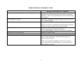
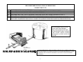
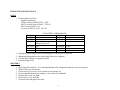
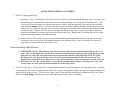
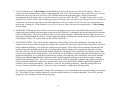
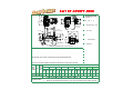
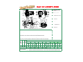
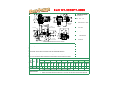
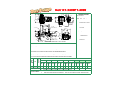
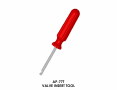
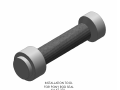
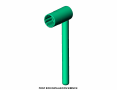
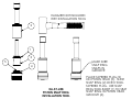
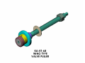
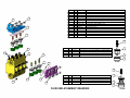
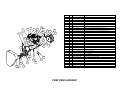
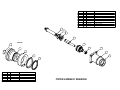
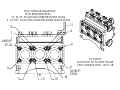
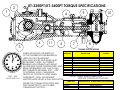
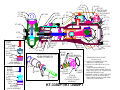
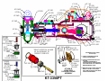
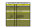
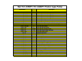
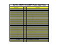
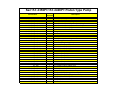
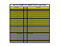
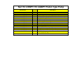
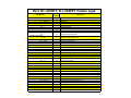
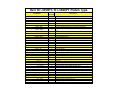
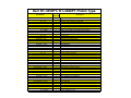
Parts & Service Manual
Kerr KT-3350PT/KT-3400PT Piston Pump
Kerr Pump Corporation
Post Office Box 735 2214 West 14th Street
Sulphur, Oklahoma 73086
Phone: 580-622-4207 Fax: 580-622-4206
Website-www.kerrpumps.com
[email protected]
United States and Canada
800-441-8149
KERR PUMPS SERVICE MANUAL
HDD EDITION
NEW PUMP WARRANTY
1) KERR MACHINE COMPANY (Kerr Pumps) warrants its new HDD pumps to be free from defective materials and/or
workmanship for 1000 HOURS OR ONE (1) YEAR, whichever comes first, from date of sale by distributor, provided that the
new pump is registered in accordance with Paragraph No. 2 hereof, properly installed and operated in accordance with the
Company’s Service Manual, and all other terms of this warranty agreement are complied with by the purchaser. As hereinafter
provided, this warranty includes the replacement of parts and labor to correct any deficiency. All defective parts must be
returned to the Company’s Home Office for examination before this warranty is effective. This warranty applies to parts,
which have been replaced under this warranty only so long as the original pump warranty is effective. This warranty is for the
exclusive benefit of the purchaser and is not transferable.
2) Each Distributor of a new KERR PUMP, will provide the customer with a registration blank furnished to him by the
Company which must state the date of sale, be signed by the purchaser and the Distributor, and delivered to the Home Office
of the Company within fifteen (15) days of the date of sale.
3) In the event of a claim under this warranty, made within the 1000 HOUR warranty period, the purchaser must notify the
Distributor, and the Distributor shall contact KERR PUMPS before any repairs or service calls are made.
4) All warranty claims must be sent to Kerr Pumps Home Office on the authorized warranty claim form provided by Kerr
Pumps, and available from the Distributor before any warranty claim will be considered. It is understood that Kerr Pumps
will deteriorate due to ordinary wear, therefore, the following credits shall apply to all replacement parts, labor, surface freight,
travel time and mileage allowance furnished under this warranty.
FOR 1000 HOUR CLAIMS
A.
B.
C.
D.
For the first 250 hours, 100% credit will be allowed on a current list price basis.
From 251 hours to 500 hours, 75% credit will be allowed on a current list price basis.
From 501 hours to 750 hours, 50% credit will be allowed on a current list price basis.
From 751 hours to 1000 hours, 25% credit will be allowed on a current list price basis.
-1-
The credit given to the Distributor for replacement parts or pumps under this warranty is based upon the Distributor’s net cost
paid Kerr Pumps for such replacement parts or pumps.
5) In the event of a warranty claim under this warranty made within the first 250 hours, KERR PUMPS, before any repairs are
made, shall be contacted by the Distributor and given the option of having the Distributor either repair or replace the pump.
6) Upon any claim under this warranty, other than a claim wherein KERR PUMPS at its option replaced the pump as provided in
Paragraph No. 5 hereof, the Distributor will make the necessary repairs an/or replacement, and KERR PUMPS shall allow the
cost of labor on warranty claims. The labor cost may include travel time not to exceed (8) hours of actual travel time. KERR
PUMPS will pay surface freight on warranty shipments. After making the necessary repairs and/or replacements, the
Distributor will bill the customer for the full amount due for the repair. Thereafter, the Distributor will submit the warranty
claim form provided by KERR PUMPS to the KERR PUMPS Home Office for consideration. In the event the warranty
claim is honored by KERR PUMPS a Credit Memorandum will be issued to the Distributor in the amount determined by the
table in Paragraph No. 4 hereof. Thereafter, the customer’s invoice will be credited by the Distributor in the same percentage
allowed the Distributor by KERR PUMPS.
If requested by KERR PUMPS the purchaser or the Distributor shall return the alleged defective product to KERR PUMPS
factory, freight prepaid, for examination and testing. If KERR PUMPS determines the product is defective KERR PUMPS
will either repair or replace such product with a like of KERR PUMPS manufacture, f.o.b. to the Distributor or allow the
Distributor credit to an amount equal to the invoiced value of the defective product. The responsibility of KERR PUMPS is
limited to the repairing or replacing defective material manufactured by it, provided KERR PUMPS examination discloses to
its satisfaction that such material has not been altered or repaired, other than by KERR PUMPS approved procedures, subject
to misuse, improper maintenance, negligence or accident. KERR PUMPS will not be responsible for loss of liquid or for
damage of any kind, or from any cause, to any person or property of any person, or for loss of revenue of profit, or for any
other special incidental or consequential damages.
7) The warranty applies only to new KERR PUMPS. The Company specifically excludes from this warranty the following.
A. All pistons, piston rubbers, liners, plungers, valves, plunger packing, valve springs, seals gaskets, and corrosion and/or
erosion damage caused by the fluid handled by the Company’s pump.
B. In addition, after the expiration of the pump warranty all replacement parts are no longer in warranty.
8) In extreme cases where in the opinion of KERR PUMPS, if a pump has been misused or is being misused, KERR PUMPS
reserves the option to offer to redeem the pump from the purchaser. Should the purchaser refuse to allow the pump to be
redeemed and chooses to continue improper operation, the warranty will be void.
-2-
9) Any parts or equipment which KERR PUMPS supplies and does not manufacture shall be subject only to the warranties of
KERR PUMPS vendors to the extent KERR PUMPS can enforce such warranties.
10) Any repairs to, alterations of, or work done on alleged defective products without KERR PUMPS specific written
authorization shall void KERR PUMPS warranty applicable thereto.
11) Any action for breach of warranty or other action under this agreement must be commenced within (1) year after such cause of
action arises.
This limited warranty is in lieu of all other warranties, expressed or implied, including any implied warranty or
merchantability or fitness.
-3-
KERR TROUBLE SHOOTER GUIDE
REASON OR SERVICE NEEDED
Unusual pounding, knocking broken valve spring
Loss of pressure or volume
Consistent, rhythmic knock
Packing failure (Excessive)
Abnormal wear of fluid end parts
Abnormal wear of power end parts
Heat in power end
Insufficient fluid at high speed. Check to see if the suction line is
the proper size and is not constricted, trash in line, valve partly
opened, etc. There is also a possibility of gas in the fluid causing
the roughness.
Also above. Foreign matter may be holding valves open. Worn
valves. Broken springs.
Improper bearing adjustment. Worn bearings or connecting rods.
NOTE: Valve noise is common and normal in high-speed pumps.
It should not cause concern unless it becomes erratic.
Improper installation. Improper type lubrication.
Incorrect type packing for particular installation.
(Contact Kerr Pumps if in doubt) Excessively worn plungers.
Abrasive or corrosive fluid.
Lack of oil, overload on pump, foreign matter in oil.
A new pump will run hot for a short period (2 or 3 days). Check
above for persistent heating. Pump will operate near 140˚ F.
under average conditions.
Check for air in pump by bleeding at cover caps. Too much
spring tension Reciprocating pumps have very limited pick up,
check installation section.
-4-
INSTALLATION INSTRUCTIONS (SEE ILLUSTRATION)
The importance of proper installation cannot be overstressed. As the reciprocating pump is almost unable to lift fluid, proper
suction flooding is a must. This is the First step toward satisfactory operation.
The Kerr Pumps Engineering Service will gladly advise you in your installation problems. As almost every installation
varies, you cannot exercise too much care in making certain your installation is proper.
Before Starting The Pump, read carefully the maintenance section in the following pages.
To start the pump, open the suction line valve and permit the intake chamber to fill on the pump. Air may be bled off by
opening the valve covers slightly until there is a constant fluid flow. After bleeding, open the discharge line valve and start the pump.
Roughness may occur from cavitation (air in line) or from starvation (lack of fluid). Eliminate these troubles before permitting
continuous operation.
-5-
RECOMMENDED INSTALLATION OF KERR PUMPS
FOR BEST RESULTS
(A)
(B)
(C)
(D)
(E)
(F)
PRESSURE RELIEF VALVE (OPTIONAL)
BY-PASSED FLUID SHOULD BE PIPED BACK IN SUCTION SUPPLY TANK WHEN POSSIBLE
USE FLEXIBLE HOSE IN DISCHARGE LINE WHEN POSSIBLE
DISCHARGE SHUT-OFF VALVE (OPTIONAL-USED FOR TOTAL SHUT-DOWN OR SERVICE ONLY)
DISCHARGE AND SUCTION ON EITHER SIDE OF FLUID END ON ALL MODELS.
PULSATION “DAMPENERS” MAY BE USED IN EITHER THE SUCTION OR DISCHARGE PIPING OR BOTH.
DISCHARGE DAMPENERS SHOULD BE CAPABLE OF HANDLING PUMP DISCHARGE MAXIMUM PRESSURE
AS A GENERAL RULE, FLUID
LEVEL MUST BE HIGHER
THAN THE PUMP FLUID END
AS PLUNGER PUMPS CANNOT
"LIFT” FLUID. ABOUT 10 FEET
OF HEAD IS A GOOD “RULE OF
THUMB”.
SUITABLE
FALL-OPENING
VALVE
CAUTION SHOULD BE TAKEN TO KEEP FITTINGS OUT OF THE SUCTION AND
DISCHARGE PIPING AS THESE WILL RESULT IN POOR PERFORMANCE. EACH
90-DEGREE TURN IN THESE LINES RESULTS IN GREAT LOSS OF PUMPING
EFFICIENCY.
-6-
PREVENTIVE MAINTENANCE
DAILY
1. Check crankcase oil level.
Synthetic Lubricant:
AGMA Grade (ASTM D 2422): 4 EP
SAW Viscosity Grade (J306-8): 75W-90
ISO Viscosity Grade: 150
Viscosity in SSU @ 100 F: 625-765
KD-1250
KJ-2250
KM-3250
KZ-3150
KM-3300
KP-3300
2.
3.
4.
5.
CAPACITIES (APPROXIMATE)
2 qts.
KT-3350
16 qts.
3 qts.
KT-3400
16 qts.
4 qts.
KB-3500
20 qts.
2 qts. Use 30 wt nonKA-3500 36 qts.
detergent motor oil
4 qts.
KSB-6400 36 qts.
12 qts.
KSB-6500 36 qts.
KCP-6300 24 qts.
If pump has lubricating facilities for stuffing boxes, check level of lubricant.
Maintain packing gland tension on packing (Do not over-tighten)
Visually inspect pump for apparent trouble.
Keep the pump clean.
MONTHLY
1.
2.
3.
4.
5.
6.
7.
Drain and refill crankcase. It is recommended that oil be changed after the first week of operation.
Wash oil filler cap in kerosene.
Check valves for excessive wear, broken or bent springs, etc.
Check crankshaft bearings for endplay. (See section on crankshaft)
Keep all nuts, studs, etc. tight.
Check valve covers for leaks.
Check all seals and gaskets for leaks
-7-
GENERAL
Replace any work part before its eventual failure. Use the following instructions for removal and replacement of parts. Don’t
hesitate to call on Kerr Pumps for help if necessary.
-8-
SERVICE PROCEDURES (ALL MODELS)
1. VALVES (Wing-guided type):
A. Discharge Valves: The discharge valve and seat can be exposed by first removing the discharge valve cover cap. Once
the discharge cover cap has been removed you may lift out the discharge valve spring and the discharge valve. The
valve seat will be held in place by a taper fit and must be “pulled” with an appropriate valve-pulling tool (available
from the Kerr Pumps Dealers). Once the valve and seat have been removed they should be resurfaced or replaced if
badly worn. To replace the discharge valve, first clean and inspect the seat bore for washout defects and then drop the
seat into the bore. Replace the valve into the seat and strike the top of the valve a couple of good blows utilizing a
brass bar and hammer to seat the valve seat in the fluid end valve bore. Replace the valve spring and cover cap after
inspecting the spring and the seal of the cover cap.
B. Suction Valves: The suction valves are located in the chamber directly behind the suction or end valve cover caps.
The suction valves are serviced in the identical manner as the discharge valves. Note: Discharge valves must be
removed prior to any removal of the suction valves.
Service Procedure for KZ-3150 Valves
C. DISCHARGE VALVE: The discharge valve and seat can be exposed by first removing the discharge valve cover
plate. Once the discharge cover cap has been removed you may lift out the discharge valve spring, discharge valve
and valve seat. Once the valve and seat have been removed they should be replaced if badly worn. To replace
discharge valve, first clean and inspect the seat bore for wash out defects and then drop the seat into the bore.
Replace valve in seat then valve spring and cover cap, always-inspecting o’ring seals between seats and cover caps.
D. SUCTION VALVE: The suction valves are located in the chamber directly below the discharge valve seat. The
suction valves are serviced in the identical manner as the discharge valves.
2. VALVES (Disc-type): All disc-type valves are exposed for removal in a similar manner as the wing-guided valves. Instead
of removing the valve body; the upper portion of the valve is removed by removal of the valve capscrew, spring retainer, valve
spring, and valve spacer sleeve. The valve seat is then “pulled” from the fluid-end utilizing an authorized Kerr Valve Puller.
Note: In all Kerr Pumps with disc-type valves the discharge and suction valves are identical.
-9-
3. VALVES (Ball & Seat): In Kerr Pumps with block/billet type fluid-ends the valves are ball and seat design. These are
exposed for removal/inspection by removal of the appropriate valve cover. The flat seats are kept in place by a screw-in valve
retainer that can be best removed with a Kerr Valve Wrench made for the appropriate pump. Springs are normally
incorporated with the discharge valves while the suction valves operate with a “free ball”. A copper washer/gasket is used
under all valve seats for a seal. When installing or removing a flat type valve seat a good “rap” on top of the valve wrench will
“seat/unseat” the seat and copper gasket prior final tightening or removal. Failure to “seat” the valve seat in this manner can
result in the “washing out” of the fluid-end. For pressurized suction, valves will need to be spring loaded. Call Kerr Pumps
for this change.
4. PLUNGERS: Following the removal of the suction valve, the plunger may be removed by breaking the union between the
plunger and pony rod and forcing the plunger out the back of the fluid-end. Loosening the packing nut/gland will facilitate the
removal of the plunger. The reverse of this procedure is used to install a plunger. Lubrication and some slight force may be
used to pass plunger through the packing. Always retighten the plunger and pony rod union periodically following the removal
of the plunger to insure it is securely made up and will not vibrate loose.
5. PLUNGER PACKING: This manual includes illustrations of the packing sets for each model pump. Generally, once the
plunger has been removed from the pump, the packing can be exposed for removal by completely removing whatever device is
used to tighten the packing (i.e. the packing or stuffing box nut or gland). There will be various amounts of metal rings and
packing components depending upon the type of packing and the model of pump (refer to appropriate illustration or chart).
After the removal of all rings and equipment from the stuffing box; thoroughly clean it and inspect for damage, which might
keep the new packing from working properly. If the stuffing box is in satisfactory condition, install the new packing as per the
appropriate illustration. It is a good idea to lubricate new packing with a light oil prior to installation. Most of the standard
packing used in Kerr Pumps should be tightened with the original equipment-packing wrench while the pump is running
under normal operating pressure. After a two or three hour run-in, check the packing for tightness and re-adjust as necessary.
Packing should be checked for tightness on a periodic basis, but it is not a good idea to attempt to periodically tighten the
packing as part of routine maintenance. This tends to “wear out” the packing prematurely. When the packing leaks in an
excessive amount it should be replaced. There is no value in constantly “re-tightening” leaking packing.
If your pump is equipped with optional “spring loaded” packing, there is no adjustment in this equipment during its operational
life. The stuffing box nut is initially tightened as much as possible and there is no further adjustment. Note: In all cases the
spring goes in the stuffing box before the packing rings.
- 10 -
When using the optional Kevlar or Teflon packing, be sure to rotate the “splits” so that none are “aligned” to insure that the
packing holds properly. Normally, this packing is not lubricated and requires less tension on the stuffing box nut during
operation.
CAUTION: An “airtight” seal is not desirable with this plunger packing. Some slight dripage is desirable during operation.
Attempts to tighten packing until it completely “seals off” will result in premature failure from too much friction. The Kevlar
& Teflon packing must be allowed to drip a small amount to assure normal life.
6. PONY ROD and PONY ROD PACKING: Kerr Pumps use two pony rod sealing arrangements, models KD-1250, KJ-2250,
KM-3250 and KCP-6300 use a screw in seal gland, all other models use a bolt in seal gland, these glands use press in oil seals
with snap ring retainers. Some Bolt in gland use adjustable packing arrangements with bolt in or screw in followers to adjust
packing. By unscrewing plunger from pony rod a gap may be facilitated to allow the removal of the various sealing
arrangements. A special wrench will be needed to remove and replace pony rod to crosshead. (This wrench is available from
Kerr Dealers) All pony rods have a jam nut to align tighten pony rod to crosshead, care must be exercised in installing new
seal on pony rod not to damage it.
7. DISASSEMBLY OF POWER END. (CAUTION: Prior to disassembly of any power end, the plunger, pony rod, and pony
rod seal housing must be removed.) Expose the crankshaft and connecting rods by removing the pan cover. Connecting rod
caps may now be removed and the connecting rod and crosshead should be shoved all the way to the rear (toward the fluid
end) to facilitate crankshaft removal out either side as convenient. The connecting rods and crossheads may now be taken out
the front cavity exposed by removing the crankshaft. Connecting rods may be removed from the crosshead by loosening the
setscrew and driving out the wrist pin from the crosshead. A bronze bushing is used in the rod it may be driven out of the rod
and replaced with a new bushing. Reassembly is the reverse of the above outlined sequence with the following considerations
for “fits” or tolerance:
A. General: All Kerr components are machined on modern production machine tools and are of the same specifications
and close tolerances you would expect in a modern automobile engine. It must be pointed out that at top speed (350 to
400 RPM) your pump will not even be approaching idle speed for a gasoline engine so “field fits” are possible and
practical when making repairs and replacements away from the factory. All procedures outlined below are possible
with only hand tools and absolutely no instruments, special tools, or gauges are needed.
B. Connecting rod and wrist pin: Proper fit will find the wrist pin turning freely in its bore in the connecting rod, but it
should have no “wobble” that is discernable up and down the main axis of the connecting rod. This looseness in the
- 11 -
wrist pin fit is the most probable cause of “knocking” which is traceable to the power end of most all pumps. The only
solution for loose fitting wrist pins is to discard the connecting rod wrist pin bushing and replace with a new one. If
any wear is visible on the wrist pin it should always be replaced.
C. Crankshaft End Play and Lateral adjustments: Adjustment of the Taper Roller bearings used in all Kerr Pumps is
accomplished by removing or adding shims under the bearing housing. Shims are taken out or added until the
crankshaft (without connecting rods) will turn freely, but with no endplay felt when attempting to pull or push the
jackshaft end of the crankshaft along its long axis. Some lateral adjustment is possible by removing shims from one
side of the crankshaft and adding them to the opposite side. (Note: Lateral adjustment is the “centering” of the
crankshaft in the power frame housing.)
D. Connecting Rod to Crankshaft fitting: Factory bored connecting rods will normally fit the standard crankshaft journal
just by bolting the cap on the rod with the standard rod shims being used. If the caps do require adjustment this is
accomplished by removing or adding various thicknesses of rod shims. The standard connecting rod shim used on all
Kerr Pumps is 1/32” thick and is comprised of .002” laminates, which can be “pealed “ off separately. Proper fit of the
connecting rod will allow the pump crankshaft to be rotated while not allowing in-and-out slack in the connecting rod
along its long or main axis. A well-fitted rod will have none of the in-and-out slack, but should be free enough to be
moved from side to side on the rod journal. This insures the rod not being too tight. A point of caution when installing
the connecting rod assembly in the pump is to make certain the oil holes in the rod are “UP” and not toward the bottom
of the pump. This will result in lubrication failure in these parts and the pump will fail in a short period of time. An
additionally important step is to make sure that the rod cap is bolted back on the rod as it came off. The rod and cap
carry a “mark” or “number” which allows you to match them back properly. Failure to do this will cause the rod not to
fit the journal for which it was made.
8. Power End/Fluid End Connection: A common misconception is that there is some form of fluid seal between the power end
and the fluid end. This is false. The fluid end is merely bolted to the power frame. It can be removed by breaking the
plunger connection, backing off the packing nut or gland, removing the various fluid end bolts, and sliding the entire fluid end
off the power frame. Corrosion may tend to seize the two components together making their separation difficult in some
isolated cases. On models KP-3300 and KT-3350 the bolted in stuffing box assemblies must be removed prior to removal of
the entire fluid end. They are held in place by four studs each. On all other units the stuffing boxes can be left intact. On the
remaining pumps (with the exception KD-1250B, KJ-2250B, KM-3250B, and KCP-6300) the stuffing boxes are held in place
in the fluid end by a friction or “press” fit. They should be removed with a hydraulic press if possible. These press-in type
stuffing boxes carry a gasket and/or an o-ring to insure a good seal. The boxes on the KD-1250B, KJ-2250B, KM-3250B,
and KCP-6300 are screw-in type and carry only a copper gasket.
- 12 -
Kerr Pump Maintenance
Schedule for Piston Type (PT)
Pumps
Daily
or 8 Hrs
Weekly
or 40 Hrs
Monthly
or 200 Hrs
Check Oil Level in Pump
Visual Inspection
Visual Inspection
Service
Check Oil Level in Planetary Gear
Visual Inspection
Visual Inspection
Service
Visual Inspection
Visual Inspection
Visual Inspection
Check for Water or Bentonite in
Gear Box
Check Piston Chamber for
Leaking Pistons
Check Recovery Tank for
Bentonite
Check Piston Cooling Pump for
Proper Operation
Flush Fluid End
Check Pony Rod Seals
Quarterly
or 500 Hrs
Semi-Annual
or 1000 Hrs
Yearly
or 2000 Hrs
Visual Inspection
Visual Inspection
Visual Inspection
Visual Inspection
Visual Inspection
Visual Inspection
Visual Inspection
Visual Inspection
Visual Inspection
Visual Inspection
Visual Inspection
Service
Visual Inspection
Visual Inspection
Visual Inspection
Visual Inspection
Visual Inspection
Visual Inspection
Service
Service
Service
Service
Service
Service
Visual Inspection
Visual Inspection
Visual Inspection
Visual Inspection
Service
Visual Inspection
Visual Inspection
Visual Inspection
Service
Visual Inspection
Visual Inspection
Visual Inspection
Service
Visual Inspection
Visual Inspection
Visual Inspection
Service
Visual Inspection
Visual Inspection
Visual Inspection
Service
Visual Inspection
Visual Inspection
Visual Inspection
Service
Check and Replace if Necessary
Piston Cups
Check and Replace if Necessary
Valve Inserts
Check and Replace if Necessary
Valves and Seats
Check and Replace if Necessary
Liners
Check Rod Bearings
Check Pony Rods
Visual Inspection
Visual Inspection
Visual Inspection
Visual Inspection
Visual Inspection
Visual Inspection
Check Belts
Visual Inspection
Visual Inspection
Visual Inspection
Visual Inspection
Visual Inspection
Service
KT-3350PT/KT-3400PT
4.25
2"-NPT
2.0
19.1
17.062
16.00
33.7
4X 11/16
MOUNT
HOLES
33.3
31.75
22.0
2"-NPT
1/4"-NPT
2"-NPT
DISCHARGE
9.88
33.7
18.7
19.4
19.5
5.0
7.0
1.0
4.6
6.0
9.35
9.625
19.5
4.75
9.0
46.2
3"-NPT
SUCTION
GENERAL DIMENSIONS FOR KT-3350PT-3500
KT-3350PT/KT-3400PT WITH DRIVE ASSEMBLY
4.25
2"-NPT
2.0
19.1
17.062
16.00
33.7
4X 11/16
MOUNT
HOLES
33.3
22.0
2"-NPT
1/4"-NPT
2"-NPT
DISCHARGE
9.88
19.4
4.626
5.000
7.000
1.0
4.6
6.0
4.75
46.14
9.0
19.5
31.75
40.8
33.7
18.7
9.35
3"-NPT
SUCTION
GENERAL DIMENSIONS FOR KT-3350PT/KT-3400PT (WITH DRIVE ASSEMBLY)
Kerr KT-3350PT-3000
4.25
2"-NPT
2.0
19.0
17.062
16.00
33.8
4X 11/16
MOUNT
HOLES
32.3
31.75
22.0
2"-NPT
1/4"-NPT
2"-NPT
DISCHARGE
33.8
9.88
18.7
20.6
19.5
6.0
4.75
Crankshaft:
Extension Dia. 2 15/16"
Keyway 3/4" x 3/8" or
Splined for Hyd Drive
Oil Capacity: 16 Quarts or
15.4 Liters
Connections:
3" FNPT (Suction)
2" FNPT(Dischrg)
3"-NPT
SUCTION
8.5
4.6
Stroke Length: 3.500"
Pump Weight: 1200 Pounds
20.8
1.0
No. of Pistons: 3
9.35
9.625
5.0
7.0
SPECIFICATIONS
Std Material for Fluid End:
Ductile Iron
45.75
GENERAL DIMENSIONS FOR KT-3350PT
FEATURES
Triplex Design
Heat Treated and Stress Relieved Crankshaft
Optional 8 Point Pressurized Crankcase Lubrication System
Optional Splined Crankshaft Designed to Bolt to Existing Hydraulic Drive
High Strength, Heat Treated Connecting Rods with Replaceable Bearings
High Speed, High Torque Tapered Roller Bearing (Continuous Duty Cycle)
Optional Cooling System Engineered to Extend the Life of the Pistons and Liners
New Longer Life Heat Treated and Hardened Polyurethane Inserted Valves and Seats
Piston
DIA.
INCHES
PSI
3.000"
1000
DISP
GAL
PER
REV
DISPLACEMENT
100 RPM
150 RPM
GPM
BPD
GPM
0.3213 32.1
1102
48.2
Max. Brake Horsepower Required
Technical Notes:
21
1
2
3
31
200 RPM
250 RPM
300 RPM
375 RPM 400 RPM
450 RPM 500 RPM
BPD
GPM
BPD
GPM
BPD
GPM
BPD
GPM
GPM
1653
64.3
2204
80.3
2755
96.4
3306 120.5 4133 128.5 4408 144.6 4960 160.7 5511
42
52
62
BPD GPM BPD
78
83
BPD GPM
94
BPD
104
Volumes indicated are based on 100% Volumetric Efficiency.
Horsepower required based on 90% Mechanical Efficiency.
Ratings are nominal speeds and pressures. They may vary with Kerr Pumps' written approval.
Kerr KT-3350PT-3500
4.25
2"-NPT
17.062
4X 11/16
MOUNT
HOLES
32.3
31.75
22.0
2"-NPT
No. of Pistons: 3
16.00
33.8
1/4"-NPT
SPECIFICATIONS
2.0
19.0
2"-NPT
DISCHARGE
33.8
9.88
18.7
20.6
19.5
5.0
7.0
6.0
4.75
Pump Weight: 1200 Pounds
Connections:
3" FNPT (Suction)
2" FNPT(Dischrg)
9.625
3"-NPT
SUCTION
8.5
4.6
Crankshaft:
Extension Dia. 2 15/16"
Keyway 3/4" x 3/8" or
Splined for Hyd Drive
Oil Capacity: 16 Quarts or
15.4 Liters
9.35
20.8
1.0
Stroke Length: 3.500"
Std Material for Fluid End:
Ductile Iron
45.75
GENERAL DIMENSIONS FOR KT-3350PT
FEATURES
Triplex Design
Heat Treated and Stress Relieved Crankshaft
Optional 8 Point Pressurized Crankcase Lubrication System
Optional Splined Crankshaft Designed to Bolt to Existing Hydraulic Drive
High Strength, Heat Treated Connecting Rods with Replaceable Bearings
High Speed, High Torque Tapered Roller Bearing (Continuous Duty Cycle)
Optional Cooling System Engineered to Extend the Life of the Pistons and Liners
New Longer Life Heat Treated and Hardened Polyurethane Inserted Valves and Seats
Piston
DIA.
INCHES
PSI
3.500"
1000
DISP
GAL
PER
REV
DISPLACEMENT
100 RPM
150 RPM
GPM
BPD
GPM
0.4373 43.7
1500
65.6
Max. Brake Horsepower Required
Technical Notes:
28
1
2
3
43
200 RPM
250 RPM
BPD
GPM
BPD
GPM
2250
87.5
3000 109.3 3750 131.2 4500 164.0 5625 174.9 6000 196.8 6750 218.7 7500
57
BPD
71
300 RPM
375 RPM 400 RPM
450 RPM 500 RPM
GPM
GPM
GPM
BPD
85
BPD GPM BPD
106
113
BPD GPM
128
BPD
142
Volumes indicated are based on 100% Volumetric Efficiency.
Horsepower required based on 90% Mechanical Efficiency.
Ratings are nominal speeds and pressures. They may vary with Kerr Pumps' written approval.
Kerr KT-3350PT-4000
4.25
2"-NPT
17.062
4X 11/16
MOUNT
HOLES
32.3
1/4"-NPT
No. of Pistons: 3
16.00
33.8
31.75
22.0
2"-NPT
SPECIFICATIONS
2.0
19.0
2"-NPT
DISCHARGE
33.8
9.88
18.7
20.6
19.5
5.0
7.0
4.75
8.5
4.6
Crankshaft:
Extension Dia. 2 15/16"
Keyway 3/4" x 3/8" or
Splined for Hyd Drive
Oil Capacity: 16 Quarts or
15.4 Liters
Pump Weight: 1200 Pounds
9.35
Connections:
3" FNPT (Suction)
2" FNPT(Dischrg)
9.625
20.8
6.0
1.0
Stroke Length: 3.500"
3"-NPT
SUCTION
Std Material for Fluid End:
Ductile Iron
45.75
GENERAL DIMENSIONS FOR KT-3350PT
FEATURES
Triplex Design
Heat Treated and Stress Relieved Crankshaft
Optional 8 Point Pressurized Crankcase Lubrication System
Optional Splined Crankshaft Designed to Bolt to Existing Hydraulic Drive
High Strength, Heat Treated Connecting Rods with Replaceable Bearings
High Speed, High Torque Tapered Roller Bearing (Continuous Duty Cycle)
Optional Cooling System Engineered to Extend the Life of the Pistons and Liners
New Longer Life Heat Treated and Hardened Polyurethane Inserted Valves and Seats
Piston
DIA.
INCHES
PSI
4.000"
1000
DISP
GAL
PER
REV
DISPLACEMENT
100 RPM
150 RPM
GPM
BPD
GPM
BPD
0.5712 57.1
1959
85.7
2939 114.2 3918 142.8 4898 171.4 5877 214.2 7347 228.5 7837 257.0 8816 285.6 9796
Max. Brake Horsepower Required
Technical Notes:
37
1
2
3
56
200 RPM
250 RPM
GPM
GPM
BPD
74
BPD
93
300 RPM
375 RPM 400 RPM
450 RPM 500 RPM
GPM
GPM
GPM
BPD
111
BPD GPM BPD
139
148
BPD GPM
167
BPD
185
Volumes indicated are based on 100% Volumetric Efficiency.
Horsepower required based on 90% Mechanical Efficiency.
Ratings are nominal speeds and pressures. They may vary with Kerr Pumps' written approval.
Kerr KT-3400PT-4000
4.25
2"-NPT
19.0
17.062
16.00
33.8
4X 11/16
MOUNT
HOLES
32.3
31.75
22.0
2"-NPT
1/4"-NPT
SPECIFICATIONS
2.0
2"-NPT
DISCHARGE
33.8
9.88
18.7
20.6
19.5
5.0
7.0
Std Material for Fluid End:
Ductile Iron
3"-NPT
SUCTION
8.5
4.6
Crankshaft:
Extension Dia. 2 15/16"
Keyway 3/4" x 3/8" or
Splined for Hyd Drive
Oil Capacity: 16 Quarts or
15.4 Liters
Connections:
3" FNPT (Suction)
2" FNPT(Dischrg)
9.625
4.75
Stroke Length: 4.000"
Pump Weight: 1200 Pounds
9.35
20.8
6.0
1.0
No. of Pistons: 3
45.75
GENERAL DIMENSIONS FOR KT-3350PT
FEATURES
Triplex Design
Heat Treated and Stress Relieved Crankshaft
Optional 8 Point Pressurized Crankcase Lubrication System
Optional Splined Crankshaft Designed to Bolt to Existing Hydraulic Drive
High Strength, Heat Treated Connecting Rods with Replaceable Bearings
High Speed, High Torque Tapered Roller Bearing (Continuous Duty Cycle)
Optional Cooling System Engineered to Extend the Life of the Pistons and Liners
New Longer Life Heat Treated and Hardened Polyurethane Inserted Valves and Seats
Piston
DIA.
INCHES
PSI
4.000"
1000
DISP
GAL
PER
REV
DISPLACEMENT
100 RPM
150 RPM
GPM
BPD
GPM
BPD
0.6528 65.3
2239
97.9
3359 130.6 4478 163.2 5598 195.8 6717 228.5 7837 261.1 8956 293.8 10076 326.4 11195
Max. Brake Horsepower Required
Technical Notes:
42
1
2
3
63
200 RPM
250 RPM
300 RPM
GPM
GPM
GPM
BPD
85
BPD
106
BPD
127
350 RPM 400 RPM
GPM
BPD GPM BPD
148
169
450 RPM 500 RPM
GPM
BPD GPM
190
BPD
212
Volumes indicated are based on 100% Volumetric Efficiency.
Horsepower required based on 90% Mechanical Efficiency.
Ratings are nominal speeds and pressures. They may vary with Kerr Pumps' written approval.
AP-77T
VALVE INSERT TOOL
How To Put Inserts In Valves
Using Kerr Valve Insert Tool
1) Push Valve Insert over
valve legs. Hint: (Insert
will be more pliable if
heated first-- warm to the
touch not hot).
4) While holding valve down
with thumb, rotate around
valve with tool. (Similar to
mounting a tire on a rim).
2) Put Tool between
valve and valve
insert with groove
against valve.
3) Holding Valve
insert down with
thumb.
5) Continue rotating around
valve with tool until insert is
completely in groove.
INSTALLATION TOOL
FOR PONY ROD SEAL
KA-KT-276
PONY ROD INSTALLATION WRENCH
KA-KT-277
HAMMER NOT INCLUDED
WITH INSTALLATION TOOL
2
1
3
5
MAKE SURE
SNAP RING
SNAPS IN
GROOVE
4
KA-KT-248
PISTON SNAP RING
INSTALLATION TOOL
PLACE TAPERED PLUG (3)
ON PISTON HEAD (5). SLIDE
SNAP RING (2) ONTO TOOL
TAPERED PLUG. USE SNAP
RING TOOL BODY (1) TO SEAT
SNAP RING IN PISTON HEAD
GROOVE (4).
KA-KT-68
WING TYPE
VALVE PULLER
INSTRUCTIONS FOR CHANGING WING/GUIDED VALVES
1. Remove Capscrews from Top and
End Cover Plates
4. Insert Kerr Valve Seat Puller through
valve seat with eccentric offset to
engage valve seat. NOTE: Puller stud
may be removed when pulling
wing/guided valve seats.
2. Remove Round Cover Caps; inspect
o’rings for damage;
3. Remove Discharge Spring and
Discharge Valve
5. Hold Puller Stem from turning;
Rotate large nut until seat releases
6. Remove Valve Seat from Puller;
Spacer on Puller may need to be
removed when pulling Suction Valve
Seats; Remove remaining valves
INSTRUCTIONS FOR CHANGING WING/GUIDED VALVES (cont.)
7. Remove Suction Valves, springs,
and seats through End Port
10. Install Discharge Valves after Suction
Valves have been installed, always be
sure short springs are on Suction Valve
and Long Spring on Discharge Valves
8. To Install Suction Valve & Seat,
insert Valve Seat and Valve Body
through End Port
9. Use metal rod to drive valve seat
assembly into seating area using
several firm but, not heavy blows
with a hammer
11. Install Cover Caps and torque Cover
Plate capscrews to Kerr Pump Specs
ITEM NO. QTY. PART NO.
1
1 KT-33D
2
3 KT-073HT
3
6 KA-KT-77
4
3 KT-072HT
5
3 KA-KT-34D
6
3 KP-KT-52L
7
3 KP-KT-52S
8
6 KA-KT-074HT
9
6 KA-KT-38
10 22 KA-KT-36
11 24 KA-KT-37
12
1 KA-KT-126FE
13
2 KA-KT-36B
14
1 AP-71
15
3 KA-KT-35D
11
12
9
4
DESCRIPTION
FLUID END (VESSEL ONLY)
SUCTION VALVE, HEAT TREATED, A/R WITH INSERT
ABRASIVE RESISTANT VALVE INSERT
DISCHARGE VALVE, HEAT TREATED, A/R WITH INSERT
TOP COVER CAP (DUCTILE)
VALVE SPRING (DISCHARGE) (LONG)
VALVE SPRING (SUCTION) (SHORT)
VALVE SEAT, HEAT TREATED, A/R
COVER CAP O'RING
COVER CAP STUD
COVER CAP STUD NUT
FLUID END LIFTING EYE
COVER CAP BRACKET STUD
FLUID END DRAIN PLUG
END COVER CAP (DUCTILE)
4
ITEM NO. QTY. PART NO.
1
1 KT-072HT
2
1 KA-KT-77
3
1 KA-KT-074HT
4
1 KP-KT-52L
10
13
1
7
1
DESCRIPTION
DISCHARGE VALVE, HEAT TREATED, A/R WITH INSERT
ABRASIVE RESISTANT VALVE INSERT
VALVE SEAT, HEAT TREATED, A/R
VALVE SPRING (DISCHARGE) (LONG)
2
3
2
KT-300
9
4
8
14
15
11
ITEM NO. QTY. PART NO.
1
1 KT-073HT
2
1 KA-KT-77
3
1 KA-KT-074HT
4
1 KP-KT-52S
DESCRIPTION
SUCTION VALVE, HEAT TREATED, A/R WITH INSERT
ABRASIVE RESISTANT VALVE INSERT
VALVE SEAT, HEAT TREATED, A/R
VALVE SPRING (SUCTION) (SHORT)
1
2
3
FLUID END ASSEMBLEY DRAWING
KT-305
28
29
6
28
5
27
27
26
25
30
28
23
14
7
18
2
10
11
8
15
12
19
17
22
21
33
3
20
9
1
32
4
24
16
30
31
13
ITEM NO. QTY. PART NO.
1
1 KT-235_A
2
1 KT-140_B
3
1 KT-130
4
1 KA-KM-KP-KT-195
5
1 KA-KP-KT-145
6
1 KA-KP-KT-150
7
1 KA-KP-KT-200-520
8
1 KA-KP-KT-230
9
1 KA-KP-KT-230-9
10
1 KA-KM-KP-KT-KZ-135
11
1 KA-KP-KT-132
12
1 KA-KP-KT-133
13
3 KA-KP-KT-6
14
3 KA-KP-KT-6B
15
3 KA-KP-KT-230-15
16
3 KA-KP-KT-230-16
17
2 KA-KP-KT-235-17
18
2 KA-KM-KP-KT-190-13
19
2 KA-KP-KT-235-19
20
2 KA-KM-KP-KT-190-14
21
2 KA-KP-KT-235-21
22
2 KA-KP-KT-235-22
23
2 KA-KP-KT-235-23
24
2 KA-KP-KT-235-24
25
1 KT-155
26
1 KT-205
27
2 KA-KP-KT-235-27
28
3 KA-KP-KT-160-1
29
1 KA-KP-KT-160-2
30
2 KA-KP-KT-235-30
31
1 KA-KP-KT-235-31
32
1 KA-KP-KT-235-32
33
1 KT-7
PUMP DRIVE ASSEMBLY
DESCRIPTION
BELT GUARD, PUMP DRIVE
OIL AND WATER PUMP BRACKET
BEARING HOUSING, EXTENSION SHAFT
WATER PUMP, BRONZE
OIL PUMP, 1/2" CAST IRON
SHEAVE, OIL PUMP
SHEAVE, WATER PUMP
SHEAVE, CRANKSHAFT DRIVE TO PUMPS
SHEAVE BUSHING 1 1/8"
OIL SEAL, BEARING HOUSING EXTENSION SHAFT
AUXILIARY SHAFT-SUPPLIED WITH KA-KP-KT-120
KEY- SUPPLIED WITH KA-KP-KT-230-9
BEARING HOUSING CAPSCREW (1 1/2)
BEARING HOUSING CAPSCREWS (2")
BOLT SUPPLIED WITH KA-KP-KT-230-9
WASHER SUPPLIED WITH KA-KP-KT-230-9
1/4-20UNC X 1 1/4 CAPSCREW
1/4 LOCK WASHER
1/4 WASHER
1/4-20UNC NUT
3/8-16UNC X 1 1/4
3/8 WASHER
3/8 LOCK WASHER
3/8-16-UNC HEX HEAD NUT
BELT, OIL PUMP
BELT, WATER PUMP
3/8-16UNC X 3/8 SETSCREW
JIC MALE ELBOW 1/2
SAE 37 JIC FML SWIVEL 90 TUBE ELBOW 1/4 X 1/2
SAE 37 JIC FML SWIVEL 3/8 X 1/2
SAE JIC MALE CONNECTOR 1/4 X 1/8
SAE 37 JIC FML SWIVEL 90 DEG TUBE ELBOW 1/4 X 1/4
BEARING HOUSING GASKET
ITEM NO. QTY. PART NO.
DESCRIPTION
1
1 KT-285-350CH LINER, 3 1/2" HEAT TREATED
2
1 KT-275
PONY ROD, PISTON PUMP TYPE
3
1 KT-265
PISTON EXTENSION ROD
4
1 KA-KT-270
PISTON EXTENSION ROD LOCK NUT
5
1 KA-KT-290-350 LINER RETAINER
6
1 KA-KT-245-350 PISTON COMPLETE 3 1/2"
7
1 KA-KT-280
CLAMP, PONY ROD TO PISTON ROD
8
1 KA-KT-295
LINER GASKET
9
1 KA-KT-32PT
PONY ROD SPLASH GUARD
2
9
7
3
PISTON
6
5
4
1
2
5
1
3
8
4
ITEM NO. QTY. PART NO.
DESCRIPTION
1
1 KA-KT-250-350 PISTON, BODY ONLY, 3 1/2"
2
1 KA-KT-263-350 PISTON CUP
3
1 KA-KT-261-350 PISTON CUP RETAINER PLATE
4
1 KA-KT-262-350 PISTON CUP SNAP RING
5
1 KA-KP-KT-246 PISTON O'RING
PISTON ASSEMBLY DRAWING
STUD TORGUE SEQUENCE
STUD REQUIREMENTS:
10 KT-59- FLUID END/LINER RETAINER STUDS
2 KT-59T- FLUID END/LINER RETAINER LINEUP STUDS
11
9
7
6
1
LINEUP
STUD
4
KT-3350PT
FLUID END TO POWER FRAME
STUD TORQUE SPEC 130 FT LB
3
5
12
10
8
2
LINEUP
STUD
KT-3350PT/KT-3400PT TORQUE SPECIFICATIONS
2
1
3
.000" - .005"
SHAFT END PLAY
4
11
5
10
9
6
7
8
TORQUE SPECIFICATIONS
REFERENCE
DESCRIPTION
TORQUE
WHEN ADJUSTING THE ENDPLAY
OF THE TAPERED ROLLER BEARINGS
1
PAN COVER CAPSCREW
21 ft-lb (28 Nm)
USED ON THE CRANKSHAFT,
2
CONNECTING ROD CAPSCREW
160 ft-lb (217 Nm)
DIAL INDICATORS AND SHIMS MUST
3
BEARING HOUSING CAPSCREW
75 ft-lb (102 Nm)
4
WRIST PIN SET SCREW AND JAM NUT
30 ft-lb (41 Nm)
BE PROPERLY USED. INCORRECT
5
PONY ROD PACKING GLAND CAPSCREW
50 ft-lb (68 Nm)
BEARING ADJUSTMENT MAY RESULT
6
CLAMP SOCKET HEAD CAPSCREW
20 ft-lb (27 Nm)
IN EXCESSIVE NOISE, TEMPERATURE, AND
7
PISTON LINER RETAINER STUD NUT
100 ft-lb (136 Nm)
REDUCED BEARING LIFE. Kerr Pumps
8
FLUID END STUD NUT
120 ft-lb (163 Nm)
RECOMMENDS BETWEEN .000” - .005”
9
PISTON EXTENSION ROD SELF-LOCKING NUT 500 ft-lb (678 Nm)
10
COVER CAP STUD NUT
200 ft-lb (271 Nm)
OF INTERNAL AXIAL CLEARANCE
11
PONY ROD
1000 ft-lb (1356 Nm)
(END PLAY OR SIDE TO SIDE) WHEN
NOTE: WHEN USING LUBRICANTS,
ASSEMBLED. FINAL ADJUSTMENT
REDUCE TORQUE AS FOLLOWS;
MUST BE MADE USING A DIAL INDICATOR.
INSURE THE CONNECTING RODS ARE
DISCONNECTED TO ALLOW FREE
CRANKSHAFT MOTION.
LUBRICANT
WHI TE LEA D
GRA PHIT E
OI L
GREA SE
A NT I - SEIZE COMPOUND
PERCENTAGE OF TORQUE REDUCTION REQUIRED
REDUCE
REDUCE
REDUCE
REDUCE
REDUCE
T ORQUE
T ORQUE
T ORQUE
T ORQUE
T ORQUE
25%
30%
40%
40%
45%
KT-155
KT-160
KT-205
KT-126FE
KT-38
KT-34D
KT-250
KT-290
KT-210
KT-33D
KT-165
KT-235
BACK PLATE
REMOVED
TO SHOW BELTS
KT-145
KT-175
KT-195
KT-200
KT-215
KT-12
KT-11
KT-34D
KT-10
AP-72
KT-38
KT-170
AP-71
KT-52L
LONG
SPRING
KA-72HT
DISCHARGE
VAVLE
KT-77
INSERT
KA-74HT
SEAT
KT-20A
KT-260
KT-265
KT-285
KT-275
KT-32PT
KT-280
*REMOVE PISTON & LINER
AS AN ASSEMBLY IN
ORDER TO SERVICE
KT-17
KT-26S
SNAP
RING
KT-18
KT-18A
KT-28
FOUR SEALS TO
CRANKCASE OIL
KT-300HT
DISCHARGE
VALVE ASSEMBLY
KT-52S
SHORT
SPRING
KT-73HT
SUCITON
VALVE
KT-77
INSERT
KT-74
SEAT
KT-305HT
SUCTION
VALVE ASSEMBLY
KT-295
KT-26
PACKING
GLAND
KT-285
KT-245
KT-265
KT-26G
GASKET
KT-26-A
PONY ROD
PACKING GLAND
ASSEMBLY
KT-3350PT/KT-3400PT
KT-22
KT-1
KT-21-000
KT-24
KT-120-8
TROUBLESHOOTING GUIDE
for Kerr Pump
1) CHECK FOR LEAKING PISTONS
- REPLACE IF NECESSARY
2) CHECK FOR PROPER FLUID FLOW
TO PUMP
- MINIMUM REQUIREMENT 3"
SUCTION HOSE NO MORE THAN 50’
LONG WITH 30 PSI OF CONTINUOUS
PRESSURE FEEDING PUMP
3) REMOVE VALVE COVER CAPS AND
INSPECT VALVES & VALVE SEATS
FOR FOREIGN OBJECTS AND WEAR
- REPLACE IF NECESSARY
KT-165
KT-235
BACK PLATE
REMOVED
TO SHOW BELTS
KT-145
KT-175
KT-155
KT-160
KT-205
KT-126FE
KT-38
KT-33D
KT-34D
KT-250
KT-290
KT-210
KT-195
KT-200
KT-215
KT-12
KT-30
KT-11
KT-34D
KT-10
AP-72
KT-38
KT-170
AP-71
KT-52L
LONG
SPRING
KA-72HT
DISCHARGE
VAVLE
KT-77
INSERT
KA-74HT
SEAT
KT-260
*REMOVE PISTON & LINER
AS AN ASSEMBLY IN
ORDER TO SERVICE
KT-300HT
DISCHARGE
VALVE ASSEMBLY
KT-52S
SHORT
SPRING
KT-73HT
SUCITON
VALVE
KT-77
INSERT
KT-74
SEAT
KT-305HT
SUCTION
VALVE ASSEMBLY
KT-285
KT-275
KT-32PT
KT-280
KT-265
KT-17
KT-18
KT-18A
KT-26S
SNAP
RING
KT-28
TWO SEALS TO
CRANKCASE OIL
KT-22
KT-20A
KT-1
KT-24
KT-120-8
KT-21-000
TROUBLESHOOTING GUIDE
for Kerr Pump
1) CHECK FOR LEAKING PISTONS
- REPLACE IF NECESSARY
KT-295
KT-285
KT-245
KT-265
KT-26G
GASKET
KT-29
KT-26M
WIPER
PACKING
SEAL
GLAND
KT-26M-A
PONY ROD
PACKING GLAND
ASSEMBLY
KT-3350PT
2) CHECK FOR PROPER FLUID FLOW
TO PUMP
- MINIMUM REQUIREMENT 3"
SUCTION HOSE NO MORE THAN 50’
LONG WITH 30 PSI OF CONTINUOUS
PRESSURE FEEDING PUMP
3) REMOVE VALVE COVER CAPS AND
INSPECT VALVES & VALVE SEATS
FOR FOREIGN OBJECTS AND WEAR
- REPLACE IF NECESSARY
Kerr KT-3350PT/ KT-3400PT Piston Type Pump
Part Number
KT- 1
*KT- 1-400PT
KT- 2
*KT- 2-400
KT- 3
KT- 4
*KT- 4-400
KA-KB-KCP-KP-KSBKT- 6
KA-KB-KCP-KP-KSBKT- 6B
KT- 7
*KT- 7-400
KT- 8-005
*KT- 8-005-400
KT- 8-010
*KT- 8-010-400
KT- 8-015
*KT- 8-015-400
KB-KSB-KT- 9
KT- 10
KA-KB-KCP-KP-KSBKT- 11
KT- 12
AP- 16
AP- 16-5
KA-KT- 17
KA-KT- 17T
KA-KT- 18
KA-KT- 18A
KA-KT- 19
KT- 20
KT- 20A
No.
Required
Description
1
1
1
1
1
1
1
Pump Case
Pump Case
Crankshaft-Heat Treated
Crankshaft-Heat Treated (for KT-3400)
Crankshaft Oil Seal
Bearing Housing (Blind Side)
Bearing Housing (Blind Side)
9
Bearing Housing Capscrews
3
2
2
2
1
Bearing Housing Capscrews 2"
Bearing Housing Gaskets
Bearing Housing Gaskets
Main Bearing Adjusting Shims .005
Main Bearing Adjusting Shims .005
Main Bearing Adjusting Shims .010
Main Bearing Adjusting Shims .010
Main Bearing Adjusting Shims .015
Main Bearing Adjusting Shims .015
Main Bearings
Pan Cover
14
1
1
1
3
3
3
3
3
3
3
Pan Cover Capscrews
Pan Cover Gasket
Breather Cap (Oil Filler)
Breather Cap Filler Tube
Crosshead
Crosshead (Tapered)
Wrist Pin
Wrist Pin Bushing
Wrist Pin Set Screws & Nut
Connecting Rod (Inserted Both Ends)
Connecting Rod Only (No Inserts - Requires inserts both ends)
Kerr KT-3350PT/ KT-3400PT Piston Type Pump
Part Number
KT- 21-000
KT- 21-015
KT- 21-030
KT- 21-045
KT- 21-060
KA-KT- 22
KT- 24
KA-KT- 26
KA-KT- 26A
KA-KT- 26G
*KA-KT- 26G-400
KA-KT- 26S
KA-KT- 28
KA-KT- 30
KA-KT- 32PT
KT- 33
KA-KT- 34
KA-KT- 35
KA-KT- 36
KA-KT- 36B
KA-KT- 37
KA-KT- 38
KP-KT- 52L
KP-KT- 52S
KA-KT- 59
KA-KT- 59T
KA-KT- 60
KA-KT 68
AP- 71
AP- 72
KT- 71PT
KT- 072HT
KT- 073HT
No.
Required
3
3
3
3
3
6
6
3
3
3
6
3
3 sets
12
3
1
3
3
22
2
24
6
3
3
10
2
24
1
1
3
1
3
3
Description
Connecting Rod Insert Bushing (Std)
Connecting Rod Insert Bushing (.015)
Connecting Rod Insert Bushing (.030)
Connecting Rod Insert Bushing (.045)
Connecting Rod Insert Bushing (.060)
Connecting Rod Capscrew
Connecting Rod Shims (Laminated)
Pony Rod Packing Gland
Pony Rod Gland Assembly (Pony Rod, Snap Ring, Seals)
Pony Rod Gland Gasket
Pony Rod Gland Gasket
Pony Rod Gland Snap Ring
Pony Rod Seal (4 Seals per Set)
Pony Rod Packing Gland Capscrews
Pony Rod Splash Guard
Fluid End Vessel Only
Top Cover Cap
End Cover Cap
Cover Cap Stud
Cover Cap Bracket Stud
Cover Cap Stud Nut
Cover Cap O' Ring
Valve Spring (Discharge) (Long)
Valve Spring (Suction) (Short)
Fluid End/Liner Retainer Stud
Fluid End/Liner Retainer Alignment Stud
Fluid End/Liner Retainer Stud Nut
Valve Puller Wing Type
Drain Plug
Oil Level Plug
KT-3350PT Rebuild Gasket Kit Complete
Discharge Valve, Heat Treated, A/R with Insert
Suction Valve, Heat Treated, A/R with Insert
Kerr KT-3350PT/ KT-3400PT Piston Type Pump
Part Number
KA-KTKA-KTKTKTKTKTKT*KTKTKA-KTKA-KTKT*KTAPKTKTKA-KTKA-KTKTKA-KTKA-KP-KTKA-KP-KTKA-KP-KTKA-KP-KTKA-KTKA-KTKA-KTKTKTKTKTKA-KTKTKTKA-KM-KP-KT-
074HT
77
120-6
120-8
120-8-400PT
125-6
125-8
125-8-400PT
126BH
126FE
127
130
130-400PT
135
140LH
140RH
145
150
155
160
160-1
160-2
160-3
160-4
160-5
160-6
161
165
170
175
176
180
190A
190
190-2
No.
Required
6
6
1
1
1
1
1
1
1
1
1
1
1
1
1
1
1
1
1
1
1
1
5
1
3
3
1
1
1
2
1
3
1
1
1
Description
Valve Seat, Heat Treated, A/R
Abrasive Resistant Valve Insert
Crankshaft, Splined Hydraulic Drive 40 Tooth Spline
Crankshaft, Splined Hydraulic Drive 21 Tooth Spline
Crankshaft, Splined Hydraulic Drive 21 Tooth Spline
Bearing Housing, Hydraulic Drive # 6
Bearing Housing, Hydraulic Drive # 8
Bearing Housing, Hydraulic Drive # 8
Bearing Cap Lifting Eye
Fluid End Lifting Eye
# 8 Auburn Housing Gasket
Bearing Housing, Extension Shaft Side
Bearing Housing, Extension Shaft Side
Oil Seal, Bearing Housing Extension Shaft
Bracket, Oil and Water Pumps (Left-Hand Drive)
Bracket, Oil and Water Pumps (Right-Hand Drive)
Oil Pump, 1/2" Cast Iron
Sheave, Oil Pump
Belt, Oil Pump
Oil Manifold
Oil Manifold 90 Degree Elbow
90 Degree Tube Fitting 1/2 (Supplied with hose)
Male Pipe Rigid 1/4 x 1/8 (Supplied with hose)
Oil Manifold Plug
Fitting, Crosshead Oil Injector
Fitting, Female Swivel (Supplied with hose)
Oil Manifold Gasket
Oil Line, Pump to Oil Manifold
Oil Line, Pump to Oil Sump
Oil Line, Manifold to Bearing Housing
Oil Line, Manifold to Planetary Gear
Oil Line, Manifold to Crosshead
Piston Chamber Spray Unit Complete
Piston Chamber Cover
Water Manifold Plug
Kerr KT-3350PT/ KT-3400PT Piston Type Pump
Part Number
KA-KM-KP-KTKA-KM-KP-KTKA-KM-KP-KTKA-KM-KP-KTKA-KM-KP-KTKA-KP-KTKA-KP-KTKA-KM-KP-KTKA-KM-KP-KTKA-KM-KP-KTKTKA-KTKA-KM-KP-KTKA-KM-KP-KTKTKTKTKTKTKTKTKTKA-KTKTKA-KM-KP-KTKTKTKA-KP-KTKA-KP-KTKTKTKA-KP-KTKA-KP-KTKA-KP-KTKA-KP-KT-
190-3
190-4
190-5
190-8
190-9
190-10
190-11
190-12
190-13
190-14
191
192
195
197
200-520
200-320
200-260
200-175
205-041
205-039
205-037
205-035
210
215
216
220
225
230
230-9
235LH
235RH
235-17
235-19
235-21
235-22
No.
Required
4
1
1
2
2
2
2
3
4
4
1
1
1
1
1
1
1
1
1
1
1
1
1
1
1
1
3
1
1
1
1
2
2
2
2
Description
Water Manifold/Oil Manifold Bolt
Water Manifold 90 Degree Fitting
Water Manifold Quick Coupling
Piston Chamber Cover Inspection Glass Wing Nut
Piston Chamber Cover Inspection Glass Capscrew
Piston Chamber Cover Wing Nut
Piston Chamber Cover Setscrew
Fitting, Water Jet
1/4" Lock Washer
1/4"-20 UNC Nut
Piston Chamber Cover Gasket
Piston Chamber Cover Inspection Glass
Water Pump, Bronze
Water Pump Repair Kit (Nitrile)
Sheave, Water Pump 5.2"
Sheave, Water Pump 3.2"
Sheave, Water Pump 2.6"
Sheave, Water Pump 1.75"
Belt, Water Pump A41
Belt, Water Pump A39
Belt, Water Pump A37
Belt, Water Pump A35
Water Manifold
Line, Water Pump to Manifold
3/8" Quick Connect
Line, Water Pump to Supply Tank
Line, Water Manifold to Piston Cover
Sheave, Crankshaft Drive to Pumps
Sheave Bushing
Belt Guard, Pump Drive (Left-Hand Drive)
Belt Guard, Pump Drive (Right-Hand Drive)
1/4"-20 UNC x 1 1/4" Capscrew
1/4" Flat Washer
3/8"-16 UNC x 1 1/4"
3/8" Flat Washer
Kerr KT-3350PT/ KT-3400PT Piston Type Pump
Part Number
KA-KP-KTKA-KP-KTKA-KP-KTKA-KP-KTKA-KP-KTKA-KP-KTKA-KTKA-KTKA-KTKA-KP-KTKA-KTKA-KTKA-KT*KA-KTKA-KTKA-KTKA-KTKA-KT*KA-KTKTKA-KP-KTKTKA-KTKA-KTKA-KTKTKTKTKTKTKTKTKTKTKT-
235-23
235-24
235-27
235-31
235-32
235-50
245-300
245-350
245-400
246
248
250-300
250-350
250-350-400
250-400
250-400-400
260-300
260-350
260-400
265
270
275
276
277
280
285-300CH
285-300CER
285-350CH
285-350CER
285-400CH
285-300CER-A
285-350CER-A
285-300CH-A
285-350CH-A
285-400CH-A
No.
Required
Description
2
2
2
2
1
1
3
3
3
3
1
3
3
3
3
3
3
3
3
3
3
3
1
1
3
3
3
3
3
3
3
3
3
3
3
3/8" Lock Washer
3/8"-16 UNC Hex Head Nut
3/8"-16 UNC x 3/8" Setscrew
SAE JIC Male Connector 1/4" x 1/8"
90 Degree Tube Fitting 1/4 (Supplied with hose)
Rotation Label
Piston Complete 3"
Piston Complete 3 1/2"
Piston Complete 4"
Piston O' Ring
Piston Snap Ring Installation Tool
Piston, Body Only 3"
Piston, Body Only 3 1/2"
Piston, Body Only 3 1/2"
Piston, Body Only 4"
Piston, Body Only 4"
Piston Cup Kit 3" (cup, retainer plate, snap ring)
Piston Cup Kit 3 1/2"(cup, retainer plate, snap ring)
Piston Cup Kit 4" (cup, retainer plate, snap ring)
Piston Extension Rod
Piston Extension Rod Lock Nut
Pony Rod Piston Pump Type
Installation Tool for Pony Rod Seals
Pony Rod Installation Wrench
Clamp, Pony Rod to Piston Rod
Liner, 3" Chrome
Liner, 3" Ceramic
Liner, 3 1/2" Chrome
Liner, 3 1/2" Ceramic
Liner, 4" Chrome
Liner Assembly 3" (Piston complete, rod, locknut, liner, gasket)
Liner Assembly 3 1/2" (Piston complete, rod, locknut, liner, gasket)
Liner Assembly 3" (Piston complete, rod, locknut, liner, gasket)
Liner Assembly 3 1/2" (Piston complete, rod, locknut, liner, gasket)
Liner Assembly 4" (Piston complete, rod, locknut, liner, gasket)
Kerr KT-3350PT/ KT-3400PT Piston Type Pump
Part Number
KA-KTKA-KTKTKTKA-KP-KTKA-KTKP-KTKA-KTKTKA-KTKA-KTKA-KP-KTKA-KP-KTKA-KTKA-KT-
290
295
300
305
306
320
323
324
325
326
327
330
331
450
500
*KT-3400PT part numbers
No.
Required
3
3
3
3
1
1
1
1
1
1
1
1
1
1
1
Description
Liner Retainer
Liner Gasket
A/R Discharge Valve Complete (KT-72HT, KA-KT-74HT & 52L)
A/R Suction Valve Complete (KT-73HT, KA-KT-74HT & 52S)
Valve Seat Seating Tool
Flow Meter
# 6 Planetary Gear Assembly
# 8 Planetary Gear Assembly
Planetary Adapter Kit 6" to 8"
Spline Adapter (21-40)
Spline Adapter Spacer
DO 266 SAE "C" Drive Assembly
O'Ring, #8 Auburn Input Drive Assembly
Sunstrand Motor 90 Series
3.5"-4" Tool Kit consists of (KA-KT-68, KA-KT-248, KA-KT-276KAKT-277, KA-KP-KT-306)
Kerr KT-3350PT/ KT-3400PT Piston Type
Part Number
KT- 1
*KT- 1-400PT
KT- 2
*KT- 2-400
KT- 3
KT- 4
*KT- 4-400
KA-KB-KCP-KP-KSBKT- 6
KA-KB-KCP-KP-KSBKT- 6B
KT- 7
*KT- 7-400
KT- 8-005
*KT- 8-005-400
KT- 8-010
*KT- 8-010-400
KT- 8-015
*KT- 8-015-400
KB-KSB-KT- 9
KT- 10
KA-KB-KCP-KP-KSBKT- 11
KT- 12
AP- 16
AP- 16-5
KA-KT- 17
KA-KT- 17T
KA-KT- 18
KA-KT- 18A
KA-KT- 19
KT- 20
KT- 20A
KT- 21-000
KT- 21-015
KT- 21-030
KT- 21-045
KT- 21-060
KA-KT- 22
No.
Required
Description
1
1
1
1
1
1
1
Pump Case
Pump Case
Crankshaft-Heat Treated
Crankshaft-Heat Treated (for KT-3400)
Crankshaft Oil Seal
Bearing Housing (Blind Side)
Bearing Housing (Blind Side)
9
Bearing Housing Capscrews
3
2
2
2
1
Bearing Housing Capscrews 2"
Bearing Housing Gaskets
Bearing Housing Gaskets
Main Bearing Adjusting Shims .005
Main Bearing Adjusting Shims .005
Main Bearing Adjusting Shims .010
Main Bearing Adjusting Shims .010
Main Bearing Adjusting Shims .015
Main Bearing Adjusting Shims .015
Main Bearings
Pan Cover
14
1
1
1
3
3
3
3
3
3
3
3
3
3
3
3
6
Pan Cover Capscrews
Pan Cover Gasket
Breather Cap (Oil Filler)
Breather Cap Filler Tube
Crosshead
Crosshead (Tapered)
Wrist Pin
Wrist Pin Bushing
Wrist Pin Set Screws & Nut
Connecting Rod (Inserted Both Ends)
Connecting Rod Only (No Inserts - Requires inserts both ends)
Connecting Rod Insert Bushing (Std)
Connecting Rod Insert Bushing (.015)
Connecting Rod Insert Bushing (.030)
Connecting Rod Insert Bushing (.045)
Connecting Rod Insert Bushing (.060)
Connecting Rod Capscrew
Kerr KT-3350PT/ KT-3400PT Piston Type
Part Number
No.
Required
KT- 24
KA-KT- 26
KA-KT- 26A
KA-KT- 26G
*KA-KT- 26G-400
KA-KT- 26S
KA-KT- 26M
6
3
3
3
6
3
3
KA-KT- 26M-A
3
KA-KT- 28
KA-KT- 29
KA-KT- 30
KA-KT- 32PT
KT- 33
KA-KT- 34
KA-KT- 35
KA-KT- 36
KA-KT- 36B
KA-KT- 37
KA-KT- 38
KP-KT- 52L
KP-KT- 52S
KA-KT- 59
KA-KT- 59T
KA-KT- 60
KA-KT 68
AP- 71
AP- 72
KT- 71PT
KT- 072HT
KT- 073HT
KA-KT- 074HT
KA-KT- 77
KT- 120-6
KT- 120-8
KT- 120-8-400PT
KT- 125-6
KT- 125-8
*KT- 125-8-400PT
KT- 126BH
3 sets
3
12
3
1
3
3
22
2
24
6
3
3
10
2
24
1
1
3
1
3
3
6
6
1
1
1
1
1
1
1
Description
Connecting Rod Shims (Laminated)
Pony Rod Packing Gland
Pony Rod Gland Assembly (Pony Rod, Snap Ring, Seals)
Pony Rod Gland Gasket
Pony Rod Gland Gasket
Pony Rod Gland Snap Ring
Pony Rod Gland Snap Ring Type for KA-KT-29 Seal Kit
Pony Rod Gland Assembly (Pony Rod Gland, Snap Ring, 2 Seals, & 1
Wiper)
Pony Rod Seal (4 Seals per Set)
Pony Rod Seal Kit (2 Seals & 1 Wiper per Set)
Pony Rod Packing Gland Capscrews
Pony Rod Splash Guard
Fluid End Vessel Only
Top Cover Cap
End Cover Cap
Cover Cap Stud
Cover Cap Bracket Stud
Cover Cap Stud Nut
Cover Cap O' Ring
Valve Spring (Discharge) (Long)
Valve Spring (Suction) (Short)
Fluid End/Liner Retainer Stud
Fluid End/Liner Retainer Alignment Stud
Fluid End/Liner Retainer Stud Nut
Valve Puller Wing Type
Drain Plug
Oil Level Plug
KT-3350PT Rebuild Gasket Kit Complete
Discharge Valve, Heat Treated, A/R with Insert
Suction Valve, Heat Treated, A/R with Insert
Valve Seat, Heat Treated, A/R
Abrasive Resistant Valve Insert
Crankshaft, Splined Hydraulic Drive 40 Tooth Spline
Crankshaft, Splined Hydraulic Drive 21 Tooth Spline
Crankshaft, Splined Hydraulic Drive 21 Tooth Spline
Bearing Housing, Hydraulic Drive # 6
Bearing Housing, Hydraulic Drive # 8
Bearing Housing, Hydraulic Drive # 8
Bearing Cap Lifting Eye
Kerr KT-3350PT/ KT-3400PT Piston Type
Part Number
KA-KT- 126FE
KA-KT- 127
KT- 130
*KT- 130-400PT
AP- 132
AP- 135
KT- 140LH
KT- 140RH
KA-KT- 145
KA-KT- 150
KT- 155
KA-KT- 160
KA-KP-KT- 160-1
KA-KP-KT- 160-2
KA-KP-KT- 160-3
KA-KP-KT- 160-4
KA-KT- 160-5
KA-KT- 160-6
KA-KT- 161
KT- 165
KT- 170
KT- 175
KT- 176
KA-KT- 180
KT- 190A
KT- 190
KA-KM-KP-KT- 190-2
KA-KM-KP-KT- 190-3
KA-KM-KP-KT- 190-4
KA-KM-KP-KT- 190-5
KA-KM-KP-KT- 190-8
KA-KM-KP-KT- 190-9
KA-KP-KT- 190-10
KA-KP-KT- 190-11
KA-KM-KP-KT- 190-12
KA-KM-KP-KT- 190-13
KA-KM-KP-KT- 190-14
KT- 191
KA-KT- 192
KA-KM-KP-KT- 195
KA-KM-KP-KT- 197
KT- 200-520
No.
Required
1
1
1
1
1
1
1
1
1
1
1
1
1
1
5
1
3
3
1
1
1
2
1
3
1
1
1
4
1
1
2
2
2
2
3
4
4
1
1
1
1
1
Description
Fluid End Lifting Eye
# 8 Auburn Housing Gasket
Bearing Housing, Extension Shaft Side
Bearing Housing, Extension Shaft Side
Extension Shaft
Oil Seal, Bearing Housing Extension Shaft
Bracket, Oil and Water Pumps (Left-Hand Drive)
Bracket, Oil and Water Pumps (Right-Hand Drive)
Oil Pump, 1/2" Cast Iron
Sheave, Oil Pump
Belt, Oil Pump
Oil Manifold
Oil Manifold 90 Degree Elbow
90 Degree Tube Fitting 1/2 (Supplied with hose)
Male Pipe Rigid 1/4 x 1/8 (Supplied with hose)
Oil Manifold Plug
Fitting, Crosshead Oil Injector
Fitting, Female Swivel (Supplied with hose)
Oil Manifold Gasket
Oil Line, Pump to Oil Manifold
Oil Line, Pump to Oil Sump
Oil Line, Manifold to Bearing Housing
Oil Line, Manifold to Planetary Gear
Oil Line, Manifold to Crosshead
Piston Chamber Spray Unit Complete
Piston Chamber Cover
Water Manifold Plug
Water Manifold/Oil Manifold Bolt
Water Manifold 90 Degree Fitting
Water Manifold Quick Coupling
Piston Chamber Cover Inspection Glass Wing Nut
Piston Chamber Cover Inspection Glass Capscrew
Piston Chamber Cover Wing Nut
Piston Chamber Cover Setscrew
Fitting, Water Jet
1/4" Lock Washer
1/4"-20 UNC Nut
Piston Chamber Cover Gasket
Piston Chamber Cover Inspection Glass
Water Pump, Bronze
Water Pump Repair Kit (Nitrile)
Sheave, Water Pump 5.2"
Kerr KT-3350PT/ KT-3400PT Piston Type
Part Number
KT- 200-320
KT- 200-260
KT- 200-175
KT- 205-041
KT- 205-039
KT- 205-037
KT- 205-035
KA-KT- 210
KT- 215
KA-KM-KP-KT- 216
KT- 220
KT- 225
KA-KP-KT- 230
KA-KP-KT- 230-9
KT- 235LH
KT- 235RH
KA-KP-KT- 235-17
KA-KP-KT- 235-19
KA-KP-KT- 235-21
KA-KP-KT- 235-22
KA-KP-KT- 235-23
KA-KP-KT- 235-24
KA-KP-KT- 235-27
KA-KP-KT- 235-31
KA-KP-KT- 235-32
KA-KP-KT- 235-50
KA-KT- 245-300
KA-KT- 245-350
KA-KT- 245-400
KA-KP-KT- 246
KA-KT- 248
KA-KT- 250-300
KA-KT- 250-350
*KA-KT- 250-350-400
KA-KT- 250-400
KA-KT- 250-400-400
KA-KT- 260-300
KA-KT- 260-350
*KA-KT- 260-400
KT- 265
KA-KP-KT- 270
KT- 275
No.
Required
1
1
1
1
1
1
1
1
1
1
1
3
1
1
1
1
2
2
2
2
2
2
2
2
1
1
3
3
3
3
1
3
3
3
3
3
3
3
3
3
3
3
Description
Sheave, Water Pump 3.2"
Sheave, Water Pump 2.6"
Sheave, Water Pump 1.75"
Belt, Water Pump A41
Belt, Water Pump A39
Belt, Water Pump A37
Belt, Water Pump A35
Water Manifold
Line, Water Pump to Manifold
3/8" Quick Connect
Line, Water Pump to Supply Tank
Line, Water Manifold to Piston Cover
Sheave, Crankshaft Drive to Pumps
Sheave Bushing
Belt Guard, Pump Drive (Left-Hand Drive)
Belt Guard, Pump Drive (Right-Hand Drive)
1/4"-20 UNC x 1 1/4" Capscrew
1/4" Flat Washer
3/8"-16 UNC x 1 1/4"
3/8" Flat Washer
3/8" Lock Washer
3/8"-16 UNC Hex Head Nut
3/8"-16 UNC x 3/8" Setscrew
SAE JIC Male Connector 1/4" x 1/8"
90 Degree Tube Fitting 1/4 (Supplied with hose)
Rotation Label
Piston Complete 3"
Piston Complete 3 1/2"
Piston Complete 4"
Piston O' Ring
Piston Snap Ring Installation Tool
Piston, Body Only 3"
Piston, Body Only 3 1/2"
Piston, Body Only 3 1/2"
Piston, Body Only 4"
Piston, Body Only 4"
Piston Cup Kit 3" (cup, retainer plate, snap ring)
Piston Cup Kit 3 1/2"(cup, retainer plate, snap ring)
Piston Cup Kit 4" (cup, retainer plate, snap ring)
Piston Extension Rod
Piston Extension Rod Lock Nut
Pony Rod Piston Pump Type
Kerr KT-3350PT/ KT-3400PT Piston Type
Part Number
KA-KTKA-KTKA-KTKTKTKTKTKTKTKTKTKTKTKA-KTKA-KTKTKTKA-KP-KTKA-KTKP-KTKA-KTKTKA-KTKA-KTKA-KP-KTKA-KP-KTKA-KTKA-KT-
No.
Required
276
277
280
285-300CH
285-300CER
285-350CH
285-350CER
285-400CH
285-300CER-A
285-350CER-A
285-300CH-A
285-350CH-A
285-400CH-A
290
295
300
305
306
320
323
324
325
326
327
330
331
450
500
KA-KT- 701
*KT-3400PT part numbers
Prices subject to change without notice
1
1
3
3
3
3
3
3
3
3
3
3
3
3
3
3
3
1
1
1
1
1
1
1
1
1
1
1
1
Description
Installation Tool for Pony Rod Seals
Pony Rod Installation Wrench
Clamp, Pony Rod to Piston Rod
Liner, 3" Chrome
Liner, 3" Ceramic
Liner, 3 1/2" Chrome
Liner, 3 1/2" Ceramic
Liner, 4" Chrome
Liner Assembly 3" (Piston complete, rod, locknut, liner, gasket)
Liner Assembly 3 1/2" (Piston complete, rod, locknut, liner, gasket)
Liner Assembly 3" (Piston complete, rod, locknut, liner, gasket)
Liner Assembly 3 1/2" (Piston complete, rod, locknut, liner, gasket)
Liner Assembly 4" (Piston complete, rod, locknut, liner, gasket)
Liner Retainer
Liner Gasket
A/R Discharge Valve Complete (KT-72HT, KA-KT-74HT & 52L)
A/R Suction Valve Complete (KT-73HT, KA-KT-74HT & 52S)
Valve Seat Seating Tool
Flow Meter
# 6 Planetary Gear Assembly
# 8 Planetary Gear Assembly
Planetary Adapter Kit 6" to 8"
Spline Adapter (21-40)
Spline Adapter Spacer
DO 266 SAE "C" Drive Assembly
O'Ring, #8 Auburn Input Drive Assembly
Sunstrand Motor 90 Series
3.5"-4" Tool Kit consists of (KA-KT-68, KA-KT-248, KA-KT-276KAKT-277, KA-KP-KT-306)
Oil Cooler w/110 V Fan Motor