1
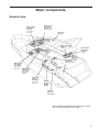
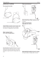
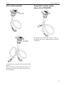
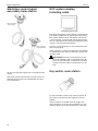
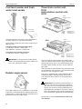
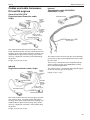
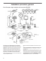
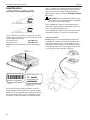
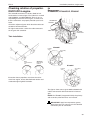
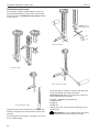
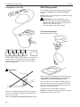
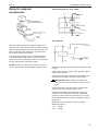
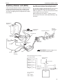
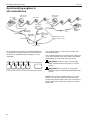
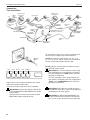
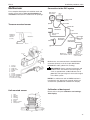
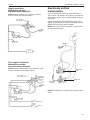
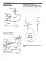
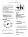
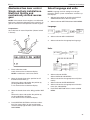
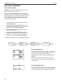
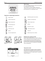
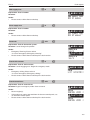
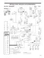
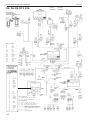
Installation procedure, general
EVC-C
D4, D6, D9, D12 and D16. Single engine installation, main and secondary helm stations.
Reverse gear installation is shown
EVC System
Tachometer
Instruments
Secondary
station
6
Start/stop
panel
12
Control
HCU
EVC
control
panel
4
8a
Gear pot.
switches.
not used
11
Main
station
Instruments
EVC.
System.
Tachometer
Key
switch
6
HCU
Relay
8
EVC System
Display
4
4
EVC
control
panel
NMEA
5
Control
Gear pot.
switches.
not used
11
3
7
Rudder
indicator
2
Diagnosis
(VODIA)
PCU
1b 1c
Fuel.
level.
sender
Engine
Freshwater.
level.
sender
Choose cable lengths to minimize the number of
connectors. Extension cables are available in different lengths. See the Major components chapter for
more information about cable lengths etc.
30
IMPORTANT! Remember that the wiring should
be routed so that there is no risk that it will be
exposed to heat, moisture or abrasion and that
joints and components are located in dry locations, easily accessible for service and repair.