1
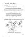
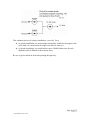
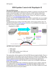
INSTALLATION GUIDE
[email protected]
Contents
0. INTRODUCTION
1. GETTING TO KNOW THE MJLJ
2. OVERVIEW OF THE INSTALLATION PROCESS
3. INSTALL THE EDIS COMPONENTS
4. INSTALL THE MJLJ
5. INSTALL 3D CONTROL
6. CONFIRM REV COUNTER OPERATION
7. MAKING AND INSTALLING THE SHIFT LIGHT KIT
8. TUNE THE MAP
9. HINTS AND TIPS
10. EDIS FAULT FINDING
Page 1 of 25
Version 1.0
© Martin Millener 2006 - 2008
0. INTRODUCTION
This guide is intended as a reference source for the installation of the Megajolt Lite
Junior (MJLJ) programmable ignition control system, Version 4.
You are invited to read the whole of this guide before doing anything!
The sections are:
• Getting to know the MJLJ – what it does, setting up your PC/laptop and using the
Configurator
• The Installation Process – what it entails and the recommended order
• EDIS Installation – how to install the EDIS components and test them
• MJLJ Installation – how to install the MJLJ components and test them
• TPS Calibration – how to calibrate a throttle position sensor
• MJLJ Communication Fault Finding – how to fault find if you cannot
communicate to the MJLJ
• EDIS Fault Finding – how to fault find if the EDIS installation does not work.
Some external sources have been used during the writing of this guide and are
acknowledged, especially:
- Brent Picasso and his AutoSport Labs websites at http://www.autosportlabs.net and
http://www.autosportlabs.org, and especially the web page at
http://www.autosportlabs.net/MJLJ_V4_vehicle_installation_guide
- Various members of the forum on that website
- Matt Dearden and his web site at http://www.cate1.co.uk/megajolt/index.php
- Various MegaSquirt web pages that detail the EDIS components, especially
http://www.megamanual.com/ms2/EDIS.htm
This guide is currently not intended for publication on the open Internet and unauthorised
copying is forbidden.
This guide is written for version 4.0.x of the MJLJ firmware (the software inside the
MJLJ unit) and the version 4.0.x of the Configurator that runs on your PC/laptop.
Page 2 of 25
Version 1.0
© Martin Millener 2006 - 2008
1. GETTING TO KNOW THE MJLJ
It is highly advisable to get to know the MJLJ before you install it in a vehicle. “Getting
to know” includes:
• Understanding what the unit does and how it does it
• Setting up your PC (or, more usually a laptop, but both are referred to as a PC
here) to communicate with the MJLJ
• Using the Configurator to access and change the MJLJ configuration.
The website describes the MJLJ as an experimental ignition controller – however it does
work exceptionally well and reliably, is extremely cost-effective and over 1000 units
have been constructed. It is worth noting the following, paraphrased from the web site…
“MJLJ components and assemblies are sold as-is, with no warranty,
expressed or implied. While much testing has been done across a
variety of engines, and it has been installed successfully on many
engine types, it has not been tested extensively across multiple engine
platforms and automotive environments, and, as such, unforeseen
problems can arise. The nature of the project is a collaborative one the intention is that the community will work together to resolve
problems and generally improve the quality of this project.”
1.1 Understanding what the MJLJ does
The standard EDIS configuration, as designed by Ford and OEM-fitted to Fiestas, Escorts
etc. circa 1989-1994 is shown below:
Page 3 of 25
Version 1.0
© Martin Millener 2006 - 2008
In the standard configuration, the EEC-IV module provides ignition timing information to
the EDIS module.
In a MJLJ installation, the MJLJ replaces, and provides most of the functionality of, the
EEC-IV, including the key task of advising the EDIS module on the ignition advance
required at the current moment, using a user-programmable advance curve (or map) that
depends on either:
• RPM only, known as 2D control
• RPM and Engine Load, known as 3D control.
3D advance curves have a choice of how Engine Load is measured:
• The reading from a Throttle Position Sensor (TPS), known as 3D TPS
• The Manifold Air Pressure (MAP), known as 3D MAP.
MJLJ receives a PIP signal from the EDIS module, indicating current RPM, and
communicates back to the EDIS module via the SAW signal (marked as SAWPW above)
indicating the amount of advance currently required:
• For 2D, only the PIP signal is used to calculate the advance
• For 3D TPS, the PIP signal and a signal from an external throttle position sensor
is used to calculate the advance
• For 3D MAP, the PIP signal and a signal from the internally mounted MAP
sensor is used to calculate the advance.
The standard OEM EDIS system is capable of running with a failed EEC-IV, in which
case the ignition advance is set to 10 degrees before top dead centre (10 BTDC)
irrespective of RPM. This allows an engine to start and run in a ‘limp-home’ mode,
although engine performance is severely limited. In a MJLJ installation, this ‘limphome’ mode still applies, so if there is a failure of the MJLJ it does not stop the engine
running.
The MJLJ unit can contain two Ignition Configurations (called Ignition Configuration 1
and Ignition Configuration 2), although only one can be active at any one time.
1.2 Setting up your PC
You can use either a PC or a laptop to communicate with and configure the MJLJ. A
laptop is usually (since it is easier to take to the car), but both are referred to as a PC here.
You will need;
• Windows 98 or later (preferably Windows XP, and this is assumed from here on)
• A RS-232 serial port capability – this can either be a real physical serial port on
the PC or a USB-Serial port adaptor plugged into a USB port.
• (optionally) A DB9 (9pin) serial port extension cable - a ‘straight through’ cable
with pin1 to pin 1, pin 2 to pin 2 etc and with one end ‘male’ (pins) and the other
end ‘female’ (sockets)
Page 4 of 25
Version 1.0
© Martin Millener 2006 - 2008
•
The supplied CD.
Setting up the PC simply involves:
• Installing the Configurator
• If required, configuring the serial port.
The following instructions assume that your CD drive is d:\
Installing the Configurator
Run d:\Version 4.0.x Configurator\mjljConfig_v4.0.x.exe, where x is the version number
of the file on the CD.
Agree to the Licence agreement and accept the default values for all the screens that
follow:
Choose Components
Choose Start Menu Folder
Choose Install Location
Close button.
This will insert a new item in your Start | Programs menu allowing you to start the
Configurator.
Note the Quickstart_README option in the Start | Programs menu item.
Setting up the Serial Port
You may need to set/check the serial port up using My Computer| Properties | Hardware |
Device Manager | Ports | Communications Port | Properties | Port Settings.
The following parameters should be set:
• Baud Rate: 4800
• Data Bits: 8
• Parity: N
• Stop Bits: 1
• Flow Control: None
1.3 Using the Configurator
Connect the PC to the Megajolt with the serial cable.
Power the Megajolt with a battery (either a 9v PP3 type or a car battery) onto the +12v
and Ground harness wires.
Start the Configurator by selecting it from your Start | Programs menu.
Page 5 of 25
Version 1.0
© Martin Millener 2006 - 2008
The current MJLJ configuration will be automatically retrieved into the Configurator
when the Configurator starts.
To retrieve the current configuration at any time, click the "Get Ignition Configuration"
icon – the icon below the menu bar with the blue vertical upwards arrow.
To update the configuration in the MJLJ so that it immediately represents what is
displayed in the Configurator, click the "Write Ignition Configuration" icon – the icon
below the menu bar with the green vertical downwards arrow.
To make the MJLJ store the configuration so that it will still be there after a power
down/up cycle, click the “Commit Configuration to Flash” icon – the 'chip' icon below
the menu bar. Forget to do this and you may get confused when you next power up the
MJLJ as the new map may not be saved!
The main areas of the Configurator are the:
• Menu
• A ‘Perspective’ Area
• Advance, RPM and Load gauges.
Within the Menu:
• The File menu item allows you to:
o Create New, Open, Save and Save As MJLJ configurations just like a
standard Windows application
o Control the Data Logging
o Exit the Configurator
• The Edit menu item allows you to edit the RPM and Load bins that control the
axes of the map:
• The Tools menu item allows you to:
o Adjust how the Configurator communicates with the MJLJ and how the
load measurement is displayed
o Set the Global Controller Options – number of cylinders (this must be
correct or else all advance calculations, and rev limit behaviour, will be
incorrect!), cranking advance, trigger wheel offset and the amount of noise
filtering performed on the PIP signal
o Calibrate your TPS (if you have one fitted)
o Set the Auxiliary Input Channel Options
• The View menu allows you to set the gauges you want to view and recover the
Advance, RPM and Load Gauges should you close them all with their Close
buttons on the top right of their areas
• The Perspective menu item controls the perspective that is displayed (see below)
• The Help menu item allows you to see the About details of the Configurator and
the current version of the firmware in the attached (and powered-up) MJLJ.
Page 6 of 25
Version 1.0
© Martin Millener 2006 - 2008
The Perspective area can display:
• The MJLJ Configuration, selected by pressing F2 at any time
• A Run Time trace showing the main parameters being sensed by the MJLJ,
selected by pressing F3 at any time
• A real time Tuning Map that shows the map in a 3D view and allows you to see
the current map point and alter the map just by using the keyboard, selected by
pressing F4 at any time.
Within the MJLJ Configuration Perspective, you use the Ignition Map tab to set up the
ignition map you require. To do this:
• Modify the data in the RPM bins to the required values (via the Edit | Edit RPM
and Load Bins menu item) – must be multiples of 100 RPM – making sure that
the numbers increase from left to right
• Modify the data in the Load bins. If you are using 3D MAP then the values are in
KPa (100KPa = atmospheric pressure). If using 3D TPS the values are for your
specific TPS (see Calibrating the TPS section, below). Normally, you have the
lowest KPa value at the left of the setup window which means the lowest value is
at the top of the Load bin axis
• Modify the individual map sites (i.e. the 10 x 10 matrix) to give the advance
required at each RPM and Load combination. Generally, advance increases as
RPM increases and also increases as vacuum or throttle position increases – so
starting in the bottom left corner of the map, advance figures generally increase
both to the right and upwards.
Within the Configuration Perspective tab, you use the Options tab to set up:
• The four user programmable outputs (Output 1 … Output 4) , where you can
specify:
o Whether the output triggers on RPM, Load or the Auxiliary input
o Whether the output (which switches the appropriate connector pin to
ground or leaves it open circuit) is normally open circuit then grounded
when the trigger point is reached (Mode = Normal) or it is normally
grounded then open circuited when the trigger point is reached (Mode =
Invert)
o The trigger point in either RPM, Load or Auxiliary input terms Note:
When the trigger point is RPM, there is a 100 rpm hysteresis at the trigger
point. For example, if you set the trigger point as 6500rpm, then the
programmable output will trigger at 6500rpm and continue to be triggered
until the rpm becomes 6400rpm or less
• The Shift Light output, where you can specify the RPM at which the Shift Light
output becomes grounded – this output is open circuit at engine speeds less than
the Shift Light setting
Page 7 of 25
Version 1.0
© Martin Millener 2006 - 2008
•
The Rev Limiter output, where you can specify the RPM at which the Rev
Limiter output becomes grounded – this output is open circuit at engine speeds
less than the Rev Limiter setting. Note: The value of this setting minus 100 rpm
is also the point at which the MJLJ fixes the ignition advance to 0 BTDC, to give
the effect of a “soft” rev limit – an engine under load with an advance of 0 BTDC
is very reluctant to increase its rpm, even when it receiving sparks.
For the configurable outputs:
• Outputs 1 to Output 4 are normally used to control devices like fans, intercooler
sprays, etc. They are also commonly used to trigger a set of ‘progressive’ shift
lights rather than using just the single Shift Light output
• The Shift Light output is normally used to trigger an external shift light
• The Rev Limiter output is normally used to achieve a “hard” rev limit by stopping
the sparks completely. This could be done by powering a transistor/MOSFET or
a solid state/mechanical relay to either cut the power to the ignition coils or earth
the coil –ve connections through a low-value resistor to stop sparks being
generated by the coil
• The maximum electrical load that can be switched is 500mA per output, subject to
an overall maximum of about 2 Amps at any one time. If you exceed these limits,
it is highly likely that you will damage one or more of the components in the
MJLJ unit.
Within the Runtime Perspective, you can see a runtime trace of the major MJLJ
parameters. You can select which ones are displayed, the update interval, the zoom
factor of the display and clear the display using the controls and icons above the trace
window.
Within the Tuning Perspective, you can see the current map in a 3D view, the current
advance bin on the map and alter any advance bin using the keyboard. The keys to use
are shown on the 3D view.
Page 8 of 25
Version 1.0
© Martin Millener 2006 - 2008
2. OVERVIEW OF THE INSTALLATION PROCESS
The recommended installation process is:
• Install the EDIS components and verify that the engine will start in the ‘limphome’ mode
• Install the MJLJ and verify that it operates in 2D mode
• If using 3D control, install and verify the 3D capability:
o If using 3D MAP, connect the MAP sensor to a suitable vacuum point and
verify that the MJLJ operates in 3D MAP mode
o If using 3D TPS, install and connect a TPS, calibrate the Engine Load bins
on the advance map in the MJLJ and verify that the MJLJ operates in 3D
TPS mode
• Ensure that the rev counter operates correctly
• Tune the advance map and programmable outputs as required.
Even though it might seem exciting to install the MJLJ with its full capabilities as soon as
possible, it is better to do an orderly and controlled install rather than having to sort out,
potentially, multiple problems if immediate success is not achieved.
Refer to the file MJLJ V4.0 Connections v1.0.pdf on the CD for schematic wiring
diagrams for 4-, 6- and 8-cylinder EDIS/MJLJ installations.
Page 9 of 25
Version 1.0
© Martin Millener 2006 - 2008
3. INSTALL THE EDIS COMPONENTS
The EDIS components to be installed are:
• The trigger wheel
• The VR sensor
• The EDIS module
• The wasted spark coilpack(s)
• Plug leads.
Trigger Wheel
The trigger wheel is a (normally) steel 36-1 wheel – it has a tooth every 10 degrees (the
“36”) with one missing (the “-1”). No other tooth combination will work.
The trigger wheel has to be mounted so that it indicates crankshaft position – mounting it
on a distributor shaft will not work.
Prime and paint the trigger wheel in a light colour – this is optional, but it does help a lot.
For a new trigger wheel with no teeth currently removed, you have to remove a tooth
yourself - an angle grinder is the best tool. It doesn’t usually matter which tooth you
remove, but you may be able to find one tooth with a small ‘pip’ on it. This is the tooth
at which the laser or water-jet cutter starts and stops – make this the tooth to remove.
Then:
• Place the wheel on the bench, with the missing tooth at the top, i.e. 12 o’clock
• Draw a dashed line on the wheel with a black permanent marker, through the
middle of the missing tooth through the centre and to the opposing tooth, i.e. a
vertical line from 12 o’clock to 6 o’clock
• Draw a solid line, through the N’th tooth before the missing one (i.e. to the left),
through the centre and to the opposite tooth, where:
o for a 4-cylider installation, N = 9, i.e. the N’th tooth is at 9 o’clock
o for a 6-cylider installation, N = 6, i.e. the N’th tooth is at 10 o’clock
o for a 8-cylider installation, N = 5, i.e. the N’th tooth is where the hour
hand is at ‘twenty past ten’
• Mark the N’th tooth end of the line
• Mount the trigger wheel - but only tighten the centre bolt finger tight.
NOTE: if the trigger wheel can be secured at any angle (e.g. just via a central bolt), then
it does not matter which tooth is removed. If the trigger wheel can only be secured at
certain positions (e.g. there are bolts that go into a backing plate through slots in the
trigger wheel) then you must remove the most appropriate tooth. In this case, continue
the instructions without removing a tooth, do a trial fit of the trigger wheel using the
alignment instructions below, and then remove the most appropriate tooth.
Page 10 of 25
Version 1.0
© Martin Millener 2006 - 2008
It is sometimes possible to recreate the functionality of a trigger wheel by machining
suitable slots directly into the crankshaft pulley. Maximum care obviously needs to be
taken if the pulley is keyed to the crankshaft, as later adjustment will not be possible.
VR sensor
Mount and set up the VR sensor so that it has a clearance of about 1mm to the trigger
wheel. Normally, the VR sensor is mounted radial to the trigger wheel, but it can be at
any angle including 90 degrees. The clearance can also be up to 3mm if necessary.
Make sure that the mounting method is secure and vibration-proof.
Rotate the trigger wheel to make sure the clearance is constant or only slightly increasing.
Set the engine at TDC of cylinder #1.
Align the trigger wheel so that the centre of the Nth tooth before the gap (the solid line
with the marked tooth goes through that tooth), in the direction of rotation of the
crankshaft (normally, but not always, clockwise when viewed from the crankshaft pulley
end) aligns with the middle of the sensor.
Tighten up centre bolt without moving anything.
Rotate the engine by hand and double check that trigger wheel:
• aligns with the VR sensor as required
• clearance with the VR sensor is still 1mm or only slightly increasing.
EDIS module
Securely mount the EDIS module in the engine bay in such a position that the wiring
harness between the VR sensor, the EDIS module and the coilpack(s) is as small as
possible.
Connect the VR sensor to the EDIS module. If the length of the tails on the VR sensor
plug and the EDIS module connector are long enough, the cables can be rejoined – make
sure you connect both signal wires and the shield.
If you need to extend the VR sensor cable then it is recommended that two core shielded
cable is used and to make sure the shield is as continuous as possible. Connect the shield
to EDIS pin 7. Note that the VR sensor cable shield is only connected to EDIS pin 7 – it
should NOT be earthed directly
The VR signal wires go:
• EDIS pins 5 and 6, for 4- and 6-cylinder installations
• EDIS pins 4 and 5, for 8-cylinder installations.
Page 11 of 25
Version 1.0
© Martin Millener 2006 - 2008
Make sure that VR sensor wires are correctly connected – the system will not work if
they are reversed. If possible, use the colours of the existing wires on the VR sensor and
EDIS module connector tails as a guide.
Connect a +12v line that is on with the ignition and when cranking, to:
• EDIS pin 8, for 4- and 6-cylinder installations, protected by a 15A fuse
• EDIS pin 6, for 8-cylinder installations, protected by a 15A fuse.
Connect a permanent ground to:
• EDIS pin 9, for 4- and 6-cylinder installations
• EDIS pin 10, for 8-cylinder installations.
Double check all the EDIS wiring. And then check it again…
Wasted Spark Coilpack(s)
Securely mount the Wasted Spark Coilpack(s) in the engine bay in such a position to
make:
• The wiring harness is as short/easy as possible
• Suitable spark plug leads to be used to connect the coilpack(s) to the spark plugs.
Connect the coilpack(s) to the EDIS module as shown in the schematic wiring diagrams
and the switched +12v car supply. The tails on the EDIS connector and coilpack
connector(s) should be able to be used to connect the correct wires together.
Plug Leads
Route and connect the plug leads to the coilpack and the spark plugs.
The standard Ford coilpack has “shouldered” towers – it is highly recommended to get
compatible plug leads – the 1100cc UK Fiesta circa 1992 seems to have compatible (and
reasonably long) leads.
The rest of this section is from http://www.megamanual.com/ms2/EDIS.htm , and is
hereby acknowledged. The coil letters relate to the diagrams on Page 2 of the file MJLJ
V4.0 Connections v1.0.pdf on the CD
There are a number of principles to wiring the spark plug leads to the coils, and a number
of 'gotchas'.
•
•
A single coil (two towers vertical when the connector is at the bottom) should fire
cylinders that are 360° apart in the firing order. For example, if your firing order
is 18436572, then 1&6, 8&5, 4&7, and 3&2 should be connected to the same
coils (they are called 'complimentary cylinders).
Do not confuse the firing order with the coil terminal numbering.
Page 12 of 25
Version 1.0
© Martin Millener 2006 - 2008
•
•
•
•
Coil A fires 'first' (i.e., correct for cylinder #1), so it should be connected to
cylinder #1 (and the complimentary cylinder). It doesn't matter which terminal on
a coil goes to which of the two complimentary cylinders (since they both fire, the
one on the exhaust stroke using vary little spark energy because of the ionized
exhaust gases).
4 cylinder (EDIS4):
o On a four cylinder engine, with a firing order of 1342, that means the coil
should be connected so that 1&4 are on coil A (left side when connector is
at bottom), and 2&3 are connected to coil B (right side). Other firing
orders are connected differently. Basically, you connect #1 and the third
cylinder in the firing order to coil A, and the second and fourth cylinders
in the firing order to coil B.
o On EDIS4, coil A is connected to pin 10 of the EDIS module, coil B is
connected to pin 12 of the EDIS module. If these are connected the wrong
way around, the coils will fire in a different order, and the spark plug
wires will need to be rearranged.
6 cylinder (EDIS6):
o On a 6 cylinder engine, the coils in a 6 terminal pack fire ACB (with ABC
left to right with the connector on the bottom). Coil A fires first and
should be connected to cylinder #1 and its complimentary cylinder. The
coil C should be connected to the cylinder that fires after #1, and its
complimentary cylinder. The remaining two cylinders should be
connected to coil B.
o For example, with a 6 cylinder having a firing order of 123456 (GM 60°
V6), you would connect coil A to 1&4, coil C to 2&5, coil B to 3&6.
o On EDIS6, coil A is connected to pin 10 of the EDIS module, coil B is
connected to pin 11 of the EDIS module, and coil C is connected to pin 12
of the EDIS module. If these are connected the other way around, the
coils will fire in a different order, and the spark plug wires will need to be
rearranged.
8 cylinder (EDIS8):
o On an eight cylinder engine, the coils fire ABCD (actually
ABCDABCDABCD...). So coil A is connected to cylinder #1 and its
complimentary cylinder, coil B is connected to the cylinder that fires after
cylinder #1 (& its compliment), coil C connects to the next cylinder (...),
and coil D connects to the next cylinder, and it's compliment. That's all of
them.
o On EDIS8, there are two coil packages, with two coils in each package.
Coil A is connected to pin 8 of the EDIS module, coil B is connected to
pin 9 of the EDIS module. Coil C is connected to pin 11 of the EDIS
module, coil D is connected to pin 12 of the EDIS module. You will need
this info to figure out which coil pack is A/B and which is C/D. Coils A
and C are on the right side of their respective coil packs, with the
connector at the bottom, B and D are on the left.
o For example, if your V8 firing order is 18436572 (Chevy V8), then 1&6
should be connected to coil A, 8&5 to coil B, 4&7 to coil C, and 3&2 to
Page 13 of 25
Version 1.0
© Martin Millener 2006 - 2008
•
coil D. Again, it doesn't matter which of the complimentary cylinders is
connected to which of the terminal on the same coil.
Cylinders may be numbered in different ways, depending on the manufacturer.
Inline four cylinders are generally 1234 from 'front' to 'back', with the front being
the opposite end from the transmission. Vee and flat engines might be numbered
with even numbers in one bank and odd on the other, or they might be numbered
down one bank then the other. ALWAYS check in a service manual to be sure.
Initial Testing
Start the engine in the normal manner – it should start!
If the engine backfires violently but doesn’t run, you probably have a coil pack/plug lead
wiring error – double check the connections.
Check the timing at idle with a strobe light. It should be exactly 10 BTDC since the
EDSI will be running in limp-home mode. You can either use the existing timing marks
but another easy way of telling is that the 8th tooth before the gap on the trigger wheel
should be opposite the sensor when the strobe flashes.
Note: Most timing lights that let you set the timing with a dial and read the alignment of
fixed TDC marks with the strobe will not work with EDIS. This is because these timing
lights use the time between sparks to compute the engine speed and advance, but the
EDIS wasted spark is giving sparks twice as often as the timing light expects for a given
rpm. If you have a 'dial back' timing light, set the dial to zero and use marks on the
pulley/trigger wheel to view the advance.
Blip the throttle, whilst checking the timing. It should be rock solid 10 BTDC.
If the timing is rock solid, but not at exactly 10 BTDC then you have an installation error
in the alignment of the trigger wheel to the VR sensor. You can either:
•
•
Undo the centre bolt on the trigger wheel and slightly rotate the trigger wheel to
remove the error
Use the Trigger Offset setting in the Tools | Global Controller Options to remove
the error – but mote that the adjustment can only be to a maximum of +/- 5
degrees. Also note that the limp home mode advance of the EDIS is not affected
by this controller offset.
Page 14 of 25
Version 1.0
© Martin Millener 2006 - 2008
4. INSTALL THE MJLJ
Mount the MJLJ somewhere away from the heat, dirt and vibration of the engine bay.
Normally it is mounted in the passenger compartment near the firewall to the engine.
It is advisable to make the harness and computer connectors easy to access.
Make and connect a suitable wiring harness to the tails on the MJLJ harness connector.
Some installations seem fine with the plain wires throughout, but others recommend that
the PIP and SAW connections to/from the EDIS module are run via a screened cable,
with the screen connected to EDIS pin 7 only and a minimum length of unshielded tails
for the PIP and SAW connections at the MJLJ end. For maximum chance of a successful
installation, screened cable for the PIP and SAW connections is recommended.
Mandatory connections are:
• +12v – live on ignition, cranking and normal running position, protected by a 5A
fuse
• Gnd – permanent earth
• PIP – to EDIS pin 1
• SAW – to EDIS pin 3.
Note that some cables carrying the PIP and SAW signals to/from the EDIS have three
cores - PIP, SAW and a spare connection to the EDIS - plus a shield. If you are
extending the cable, you only need to use 2-core cable (for PIP and SAW) with a shield
(to EDIS pin 7)
At the MJLJ end, do not connect the PIP/SAW cable shield to anything, but minimise the
length of the unshielded PIP and SAW cores to the MJLJ connector.
For 3D TPS, mandatory connections are:
• Vref – to the ‘top’ of the TPS
• TPS – to the ‘centre’ of the TPS.
Optional connections are:
• Prog Out 1 to 4
• Shift Out
• Rev Out
• Tach Out
• Option, which is used to enable on-the-fly switching between Ignition
Configurations:
o When Option is open circuit, Ignition Configuration 1 is active
o When Option is grounded to earth, Ignition Configuration 2 is active
It is optional to earth MJLJ case but there is, however, no specific requirement to do so.
Page 15 of 25
Version 1.0
© Martin Millener 2006 - 2008
Re-start the engine – it should now be running with the MJLJ controlling the ignition
advance.
Check the timing at idle with a strobe light. It should be the timing set in the map for the
idle rpm.
Blip the throttle, whilst checking the timing. It should be move according to the values
set in the map.
Check the Advance and RPM gauges in the Configurator - verify that the highlighted cell
moves only horizontally according to the RPM bins and current engine rpm, and that the
real time values of advance and RPM are correct.
Page 16 of 25
Version 1.0
© Martin Millener 2006 - 2008
5. INSTALL 3D CONTROL
3D MAP
For 3D MAP control, simply connect the MJLJ bulkhead connector to a suitable vacuum
point on the engine.
A suitable vacuum point is one that gives a good representative indication of average
manifold air pressure – take-off from a plenum chamber is best, and from the barrel of
single choke on a multiple carburettor set-up is worst.
Take care to make a secure vacuum connections throughout – leaks will affect engine
performance, give erroneous advance values and, worst-case, potentially reduce brake
efficiency in a servo-brake system.
It is recommended that the vacuum installation minimises the chance of moisture entering
the MJLJ unit and affecting the on-board MAP sensor. Techniques such as not mounting
the MJLJ well below the vacuum take off point and having a “U-bend” between the takeoff point and the MJLJ can help.
Re-start the engine – it should now be running with the MJLJ controlling the ignition
advance in a 3D MAP mode.
Check the timing at idle with a strobe light. It should be the timing set in the map for the
idle rpm and measured MAP.
Blip the throttle, whilst checking the timing using the Advance gauge in the
Configurator. It should be move according to the values set in the map – there will be
low manifold pressure (indicated by small KPa values) when the throttle is closed and
high manifold pressure (indicated by large KPa values) when the throttle is open.
3D TPS
There is a well-written and illustrated guide of installing a TPS for a MJLJ Version 3 unit
at http://www.cate1.co.uk/megajolt/installation.php.
Install the TPS mechanically and electrically connect it to the MJLJ:
• The 'top' of the TPS to MJLJ pin 7
• The 'bottom ' of the TPS to MJLJ pin 9
• The 'wiper ' of the TPS (normally the centre pin, but not guaranteed) to MJLJ pin
10
Switch on the ignition, but do not start the engine, and perform the following checks:
• The voltage at the 'top' of the TPS should be 5V ± 0.2V
• The voltage at the 'bottom' of the TPS should be 0V
Page 17 of 25
Version 1.0
© Martin Millener 2006 - 2008
•
•
•
Check the DC voltages at closed and Wide-Open-Throttle (WOT) at pin 9. They
should be close to 0V at closed and close to 5V at WOT. But anything between
0-1.5v and 3.5-5v respectively will be OK. If they aren't around those values,
then there is not enough rotation on the TPS from the throttle spindle and this, if
possible, should be corrected
The Load gauge in the Configurator should show, at closed, a Load value close to
Voltage-at-closed * 50
The Load gauge should show, at WOT, a Load value close to
Voltage-at-WOT * 50
To calibrate the TPS use the Tools | Load Axis Calibration menu item on the
Configurator.
Re-start the engine – it should now be running with the MJLJ controlling the ignition
advance in a 3D TPS mode.
Check the timing at idle with a strobe light. It should be the timing set in the map for the
idle rpm and measured TPS.
Blip the throttle, whilst checking the timing using the Advance, RPM and Load gauges in
the Configurator. The active advance bin should move according to the values set in the
map – there will be low engine load figures when the throttle is closed and high engine
load figures when the throttle is open.
Page 18 of 25
Version 1.0
© Martin Millener 2006 - 2008
6. CONFIRM REV COUNTER OPERATION
With the engine now running on the MJLJ it is now time to check the rev counter.
Assuming you have an existing rev counter, you need to find out whether it works on
either:
• A low voltage signal from somewhere in the existing ignition system - typically a
signal that varies between 0v and 12v (let’s call this Type 1), or
• A signal taken from the primary side of the coil (usually the coil –ve) which is a
mixture of a low voltage signal plus a high voltage spike (let’s call this Type 2).
For Type 1 rev counters, there are two options:
• Take the rev counter signal from the Tach Out pin on the MJLJ (pin 2)
• For 4-cylinder installations, take the rev counter signal from the CTO (Clean Tach
Out) pin (pin 11) on the EDIS module
• For 6- and 8-cylinder installations, take the rev counter signal from the IDM pin
(pin 2) on the EDIS module
Try these in the above order.
There may be a challenge in making an electrical connection to the CTO/IDM pins on the
EDIS – although the pin will be on the EDIS module, there may not be a socket and wire
on the connector for it. Some EDIS connectors have CTO/IDM sockets and wires, but
most do not.
It is possible to drill a hole in the CTO/IDM position on the connector and make a contact
with the pin, but this will need to be made solid and environmentally sound.
For Type 2 rev counters, you can connect the rev counter to a coil drive wire on the EDIS
connector.
If the rev counter works fine with this connection, then you’re all set. However, you may
find that the rev counter reads only a proportion of the actual rpm. This is because you
are taking the signal from just one of the coil primaries, which in a wasted spark coilpack
is only a proportion of the equivalent signal from a normal single winding coil primary.
You can’t just join the all the coil primaries together to connect to the rev counter but
they can be joined via a small circuit comprising a zener diode and normal diodes, as
shown on the next page:
Page 19 of 25
Version 1.0
© Martin Millener 2006 - 2008
This schematic shows a 4-cylinder installation - two coils. For a:
•
6-cylinder installation, you would simply add another 1N4004 to the negative side
of the third coil, connected to the single zener like the other two
•
8-cylinder installation, you would add two more 1N4004 diodes (one for each
additional coil) in addition to those shown above.
Be sure to get the bands on the diodes pointing the right way.
Page 20 of 25
Version 1.0
© Martin Millener 2006 - 2008
7. MAKING AND INSTALLING THE SHIFT LIGHT KIT
If you have the self-assembly DIY shift light kit, then this contains:
• A small mountable plastic box
• Three 10mm LEDs and bezels
• Three 470R resistors.
The assembly method is:
• Drill three holes in the side of the box to take the bezels
• Drill another hole in an appropriate side of the box, for your installation, to take
the wire that connects the shift lights to the MJLJ
• Put the LEDs into the bezels and push the bezels into the drilled holes
• Wire up the LEDs and resistors inside the box , using soldered connections,
according to the diagram in the wiring instructions, Take care to connect the
resistors to the correct leads on the LEDs – it does make a difference!
• You then need some four-core wire to connect the appropriate connections inside
the box to the MJLJ – computer network cable is ideal (use one twisted pair for
each connection) and cheap, but any other means of connecting four wires from
the box to the MJLJ will suffice. Thin wire can be used – the current demands are
very small.
• When you are satisfied that the circuit is correct and able to withstand vibration
etc, you can screw the base plate to the box.
You can then set up the shift lights by setting the three programmable outputs that you
have connected to the shift lights to the rpm you wish, e.g. green at 5500rpm, yellow at
6000rpm and red at 6500rpm.
Make sure that you set the Mode as “Normal” in the Options tab of the Configuration
Perspective on the Configurator.
Page 21 of 25
Version 1.0
© Martin Millener 2006 - 2008
8. TUNE THE MAP
Tuning the map is a subject which could take up as much space as the rest of these
instructions.
For a 3D TPS or MAP ignition table, the general trends on the Ignition Map tab of the
Configuration Perspective are shown below:
Vacuum increases, or
Throttle closes
RPM increases
Advance increases
Advance
increases
Pressure increases, or
Throttle opens
The normal aim is to adjust the map to achieve the best engine performance - pick up
rate, fuel consumption, lack of pinking, torque, power or whatever you are particularly
after.
The map can be altered from the Configurator whilst the engine is running. Some people
have reported that “Write Ignition Configuration” does not work reliably at high engine
rpms (above 5000 rpm). In this case, just reduce the engine rpm to a lower value, e.g.
3000 rpm, then click the Write Ignition Configuration icon and readjust the engine rpm to
the higher value.
Don’t forget to click the Commit Configuration to Flash icon to make the MJLJ save its
new configuration.
The map can be tuned on a clear road with a patient driver and assistant, but best results
are obviously obtained from a rolling road session.
Page 22 of 25
Version 1.0
© Martin Millener 2006 - 2008
9. HINTS ANDTIPS
Hint and Tip 1:
Connect your serial RS-232 lead (or another one) permanently to the MJLJ in its installed
position in the car and run the lead so that the other end of it is easily accessible to your
PC – this allows the MJLJ to be mounted in a less easily accessible position but still
allows easy use of the Configurator in the car.
Hint and Tip 2:
Use all four programmable out puts, plus the Shift Light output to drive a set of five
‘progressive’ shift lights.
Hint and Tip 3:
Use all four programmable outputs plus the Shift Light output to drive a set of five shift
lights which ‘join in the middle’ at max rpm, e.g. set:
• Output 1 to 6000 rpm and to a green light 1 (extreme left)
• Output 2 to 6500 rpm and to a yellow light 2
• Output 3 to 7000 rpm and to a red light 3
• Output 4 to 6500 rpm and to a yellow light 4
• Shift Light to 6000 rpm and to a green light 5 (extreme right).
Hint and Tip 4:
Make a visually-pleasing 36-1 trigger wheel from of a disc of aluminium with M4 capheaded steel hex bolts tapped into the circumference every 10 degrees, with one missing.
This gives the same functionality as a 36-1 steel trigger wheel.
Page 23 of 25
Version 1.0
© Martin Millener 2006 - 2008
10. EDIS FAULT FINDING
If the engine fails to start when installing the EDIS components and the wiring is checked
and checked again as OK, and the obvious voltages are correct, the following checks can
be made using a simple multimeter on DC and AC voltages.
Disconnect the 3-pin plug from the coil to stop the generation of sparks and crank the
engine on the starter motor.
VR Sensor
Test:
Measure across EDIS VR sensor pins at the EDIS main connector with the connector
disconnected from the EDIS i.e. this is the open circuit VR sensor voltage:
- should be 0 volts AC stationary
- should be non-zero volts AC cranking (from 0.3 volts to 2 volts)
Explanation: VR sensor produces a +ve and -ve swinging AC voltage as a result of the
ferrous teeth of the trigger wheel passing close to the magnet at the end of the sensor.
Wire wrapped around the magnet picks up the change in magnetic field and converts it to
an AC voltage - just like a motor in reverse, really
Demonstrates: A working VR sensor
PIP Pulse
Test:
Measure at EDIS pin 1 with the main connector connected to EDIS:
- should be battery volts DC stationary
- should be around ½ battery volts DC cranking
Explanation: The PIP pulse produced by the EDIS is a 1:1 mark/space ratio 0v to 12v
pulse train with a frequency proportional to engine rpm. When measured with a DC
voltmeter, the voltage measures around half the supply voltage, due to the 1:1 mark/space
ratio.
Demonstrates: A working VR sensor and a probably working EDIS module with regard
to generating PIP pulses
SAW Pulse
Test:
Measure at EDIS pin 3 with main connector connected to EDIS and MJLJ SAW output
connected to EDIS:
- 0 volts AC stationary
- 0 volts DC stationary
- typically 0.14 volts AC cranking
- typically 0.06 volts DC cranking
Explanation: The SAW pulse produced by the MJLJ is a 1:lots mark/space ratio pulse
train with a mark/space ratio that increases as timing tends towards TDC and an overall
Page 24 of 25
Version 1.0
© Martin Millener 2006 - 2008
frequency proportional to engine rpm. When measured with a voltmeter, the voltages are
very low since the pulse train is at 0v for most of the time. It’s not clear why the voltage
appears higher on the AC range!
Demonstrates: A working VR sensor, a probably working EDIS module with regard to
generating PIP pulses and a probably working MJLJ with regard to producing SAW
pulses
Page 25 of 25
Version 1.0
© Martin Millener 2006 - 2008