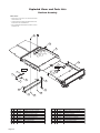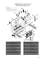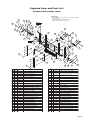
1
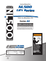
Service Manual for:
NL500
Lift Series
Public Use Wheelchair Lifts
Series A1
DOT — Public Use Lift
“DOT — Public Use Lift” verifies that this platform lift meets the
“public use lift” requirements of FMVSS No. 403. This lift may be
installed on all vehicles appropriate for the size and weight of the
lift, but must be installed on buses, school buses, and multipurpose passenger vehicles other than motor homes with a gross
vehicle weight rating (GVWR) that exceeds 4,536 kg (10,000 lb).
WARNING
Man
International Corporate Hdqrs: P.O. Box 310 Winamac, IN 46996 USA
1-800-THE LIFT ®
(574) 946-6153
FAX: (574) 946-4670
®
®
l
Read manual
before installing
or servicing lift.
Failure to do so
may result in
serious bodily
injury and/or
property damage.
TM
TM
Braun NL500 Series
"Providing Access to the World"
ua
36090 Rev. A
April
2012
Congratulations
We at The Braun Corporation wish to express our fullest appreciation
on your new purchase. With you in mind, our skilled craftsmen have designed and
assembled the finest lift available.
This manual provides service-related material. Refer to the FMVSS No. 403
Quick Reference Installation Sheet for installation instructions, operating instructions
and maintenance procedures.
Braun NL500 Series™ lifts are built for dependability and will provide years of
pleasure and independence as long as the lift is installed and serviced as specified by
a Braun certified technician, and the lift is operated by an instructed person.
Sincerely,
THE BRAUN CORPORATION
Ralph W. Braun
Chief Executive Officer
Warranty and Registration Instructions
Immediately upon receiving the lift, examine the
unit for any damage. Notify the carrier at once
with any claims.
Serial No.
Model No.
OWNER'S WARRANTY REGISTRATION
XXXXXXXXXX
XX-XXXXX
PURCHASED FROM
Two warranty/registration cards (shown right) are
protected in a clear envelope and attached to the lift
protective shipping wrap. The sales representative
must process one of the cards. The consumer must
fill out the other card and mail it to The Braun Corporation. A detailed warranty section is provided in
this manual. The warranty cards must be processed
to activate the warranty.
OWNER
DATE INSTALLED
NAME
ADDRESS
CITY
TELEPHONE
STATE
ZIP
TO VALIDATE WARRANTY
REGISTRATION CARDS MUST BE RETURNED TO THE BRAUN CORPORATION.
Sample Warranty/Registration Card
Two Braun Serial No./Series No. identification tags (shown below) are posted on the lift. One
I.D. tag is posted on the right side vertical channel. A second I.D. tag is located on the lift
mounting base. Both I.D. tags provide the product identification information provided on the
warranty/registration card. Record the information in the space provided (or document on a
copy). This information must be provided when filing a warranty claim or ordering parts.
The Braun Corporation
1-800-THE-LIFT TM
BRAUNLIFT.COM TM
DOT Public Use Lift MODEL#
XXXXXXXXXX
Max. Lifting Capacity - 600Lbs.
SERIAL NUMBER
XX-XXXXX
MFG DATE
XX/XX/XXXX
Sample Serial No./Series No. Identification Tag
Model No.
Serial No.
Date of Manufacture
Contents
Troubleshooting and Maintenance
Lift Terminology ............................................................ 2
Switch and Sensor Locations ...................................... 3
Certification Checklist Diagnostic Procedures .......... 4
Switch Adjustments....................................................... 5
LCD Diagnostic Codes . ................................................ 6
Lubrication Diagram ..................................................... 8
Maintenance and Lubrication Schedule.................. 9-11
Lift Electrical Schematic ............................................. 13
Lift Wiring Diagram ..................................................... 14
Hydraulics
Hydraulic Exploded Views and Parts Lists
Hydraulic Parts List ............................................... 16
Hydraulic Diagram ................................................. 17
Valve Block Housing............................................... 18
Hand Pump Assembly............................................ 19
Hydraulic Schematic ................................................... 20
Repair Parts
Lift Exploded Views and Parts Lists
Mounting Base........................................................ 21 Upper / Lower Control Arms.................................. 22
Inner Vertical Channel - Front................................ 23
Inner Vertical Channel - Rear................................. 24
Intermediate Vertical Channel (S-Beam) - Front...... 25
Intermediate Vertical Channel (S-Beam) - Rear........ 26
Outer Vertical Channel - Front............................... 27
Outer Vertical Channel - Rear................................ 28
Handrail Assembly.................................................. 29
Platform Assembly................................................. 30
Platform Sub-Assembly - Inner............................. 31
Platform Sub-Assembly - Inner Side Plate........... 32
Platform Sub-Assembly - Outer............................. 33
Warranty
Braun® Limited Warranty........................................ 34-36
Page Lift Terminology
Raise / Lower
Hydraulic
Cylinder
Stow / Deploy
Hydraulic
Cylinder
Mounting
Base
Raise / Lower
Hydraulic
Cylinder
(not visible)
Inner
Vertical Intermediate
Channel (2) Vertical
Channel
(S-Beam)-2
(not visible)
Outer
Vertical
Channel (2)
Pump
Module
Inner
Roll Stop
Right
Handrail
Handrail
Belt
Platform
Support Bracket (2)
POWER
STOW
UP
N
DOW
Stow / Deploy
Hydraulic
Cylinder
Inner
Platform
Upper/Lower
Control Arms (2)
Transition
Plate
Hand-Held
Attendant's
Control Pendant
Outer
Platform
Platform
Latch
Left
Handrail
Handrail
Latch
Pendant
Clip
Inboard
Inboard
(driver's side)
Rear
Left
(of vehicle)
Right
Front
(of vehicle)
Outboard
Outboard
(passenger's side)
“Arrows/30°-30°”6-13-90
Page Handrail
Belt
Receptical
Outer Barrier
Outer Barrier
Latch (2)
Outboard
Platform
Side Plates (2)
Transition Plate
Strap
Switch and Sensor Locations
Inner Roll Stop Up
Activation Block
Inner Roll Stop
Occupied Switch
15754
Inner Roll Stop Deployed Floor Level Cam (Inner)
500-0014
Inner Roll Stop Deployed Floor Level Cam (Outer)
500-0015
Platform Unfold
Limit Switch
30205
Full Out
Limit Switch
30205
Full In
Limit Switch
30205
POWER
STOW
UP
DOWN
Full In
Cam
BF00076
Full Out
Cam
BF00076
Inner Roll Stop
Deployed
Limit Switch
30205
Floor Level
Limit Switch
30205
Stow Level
Limit Switch
30205
Outer Barrier
Occupied / Raised
Microswitch
34769A
Page Certification Checklist Diagnostic Procedures
The following operations and conditions must be
functionally verified in order for the lift to be FMVSS
403/404 compliant. If an operation does not function as described or a condition is not met, follow
the referenced procedures to correct the problem
or contact a Braun Corporation Product Support
representative.
Public use vehicle manufacturers are responsible
for complying with the lift lighting requirements in
Federal Motor Vehicle Safety Standard No. 404,
Platform Lift Installations in Motor Vehicles (49 CFR
571.404).
• Vehicle movement is prevented unless the lift door is closed, ensuring the lift is stowed.
1. Verify lift door closed signal (vehicle interlock).
2. Refer to the interlock installation instructions.
• Lift operation shall be prevented unless the vehicle is stopped and vehicle movement is prevented.
1. Verify vehicle secure signal (orange 18 gauge) single conductor plug from inside valve block housing
has a +24 volt signal.
2. Refer to the interlock installation instructions.
• The platform will not fold/stow when occupied.
- Refer to Platform Unfold Switch Adjustment procedure.
• The inner roll stop will not raise if occupied.
- Check Inner Roll Stop Occupied and Inner Roll Stop Deployed Switches for wear or damage, and for
proper operation.
• The outer barrier will not raise if occupied.
- Refer to Outer Barrier Occupied Switch Adjustment procedure.
• Verify platform lighting when lift is deployed and pendant illumination when lift is powered.
1. Replace bulb(s) in the light housing.
2. Check vehicle wiring and fuses going out to lights.
• A visual and audible warning will activate if the threshold area is occupied when the platform is at least 1"
below floor level.
1. Make sure connector(s) to threshold sensors are properly connected.
2. Call Product Support.
• Platform movement is prohibited beyond the position where the inner roll stop is fully deployed (up).
- Check Inner Roll Stop Occupied and Inner Roll Stop Deployed Switches for wear or damage, and for
proper operation.
• Platform movement shall be interrupted unless the outer barrier is deployed (up).
- Check Outer Barrier Occupied / Raised limit switch, wires and connector.
- In diagnostic mode, LCD should display a value of “1” for OBAR SW when outer barrier is deployed
(up).
Page Switch Adjustments
Adjustment Procedures
Full In: When the Full In Switch is deactivated (depressed), inward travel of the lift during Stow function
is stopped. Power is removed from the pump motor
and In Solenoid.
The lift is fully stowed when the rubber bumpers are
compressed 1/8" to 3/16" and the pump shuts off.
1. Fully deploy lift and lower platform to the ground.
2. Loosen set screw and rotate front cam so that
screw is approximately at the 9:30 position.
3. Tighten set screw.
4. Stow lift.
5. If lift fully stows but pump continues to run, loosen
set screw and rotate front cam clockwise.
6. If the lift stops and is not fully stowed, loosen set
screw and rotate front cam counterclockwise.
7. Tighten set screw securely upon final adjustment.
Full Out: The Full Out Switch prohibits outward travel
of the lift during Deploy function. Power is removed
from the pump motor and the Out Valve when this
switch is activated (pressed). The platform will not
raise or lower until this switch is activated (pressed).
1. Fully deploy the lift and lower platform to the
ground.
2. Loosen set screw and rotate the rear cam so the
set screw is on top (12:00 position).
3. Rotate cam counterclockwise until switch is activated (pressed).
4. Tighten set screw securely upon final adjustment.
Platform Unfold: When the Platform Unfold Switch
is activated (pressed), it will prohibit the lift from stowing anytime the platform is deployed (unfolded) during
the Stow function. Up / Down travel of platform is only
allowed when the switch is activated (pressed).
1. No adjustment available, bend microswitch lever if
needed.
Outer Barrier Occupied: Power is removed from the
pump and Up Valve when the switch is deactivated
(depressed) while the Outer Barrier is occupied at 3”
above the ground. Power is stopped to the pump and
an audible and visual alarm will also be activated during the Up function.
1. No adjustment available, bend microswitch lever if
needed.
Inner Roll Stop Occupied: The switch interrupts
downward travel of the platform during the Down
function by removing power from the Down Valve. An
audible and visual alarm will also be activated at that
time.
The switch is deactivated (depressed) two places
during the lift cycle. First, when the Inner Roll Stop
is occupied in the range of 1" below floor level to the
point when the Inner Roll Stop is locked in the upright
position. This deactivation stops the downward travel
and triggers an alarm.
Second, when the Inner Roll Stop is in the full up and
locked position, the Inner Roll Stop Occupied Switch
is also deactivated (depressed). This does not stop
the platform or set off the alarm due to the deactivated
(depressed) Inner Roll Stop Deployed Switch.
1. No adjustment available.
Inner Roll Stop Deployed: This switch is deactivated
(depressed) when the Inner Roll Stop mechanically
locks. The purpose of this switch is to override the Inner Roll Stop Occupied switch from stopping downward
travel whenever the inner roll stop is deployed and
locked.
1. See Floor Level for adjustment procedures.
Floor Level Switch: The Floor Level Switch has two
functions. Power is removed from the pump motor and
the Up Valve by the switch when activated (pressed)
once the lifting cylinders have reached full extension.
The switch also allows threshold sensing when the
switch is deactivated (depressed) denoting that the
plaftorm is 1” below floor level.
Inner Roll Stop Deployed is automatically adjusted
when setting Floor Level.
1. Raise platform to floor level using the manual back
up pump. Stop raising platform once inboard end of
inner roll stop fully contacts vehicle floor.
2. Loosen the (4) screws attaching the microswitch bracket to the Rear Outer Vertical Channel.
3. Slide microswitch bracket down until microswitch is
activated (pressed).
4. Tighten the (4) screws attaching the microswitch bracket.
Stow Level Switch: The Stow Level Switch sets the
height at which the platform will be manually folded.
It also insures that the lift is compact enough to fit
through the lift bay opening during the Stow function.
The switch is activated (pressed) at and below Stow
Level. Power is removed from the Down Valve when
this switch is activated (pressed).
1. A good starting reference is to raise the platform
so that the Outer Vertical Channel top edge is 1/2"
lower than top edge of the Inner Vertical Channel
(red Stow Level arrow decals should be aligned).
2. Loosen the (2) screws attaching the microswitch to
the Rear Inner Vertical Channel.
3. Rotate the bottom of the microswitch bracket inward
to lower Stow Level. To raise Stow Level, rotate the
bottom of the microswitch bracket outward.
4. Tighten the (2) screws attaching the microswitch bracket.
Page LCD Diagnostic Codes
Lift_Out
®
34726
103
J37
P L A T _ UNF 1
A
REV
8.00M
C12
2430
6C5
6C5
100
VHA
100
VHA
V104
V104
U5
R21
1001
R21
1001
6C5
100
VHA
6C5
100
VHA
103
6C9
220
CFK
U5
V104
V104
V104
R48
1002
J23
1
LO
1
2430
A105T
70131
6C9
220
CFK
2430
2430
2430
A105T
70131
2430
J11
J10
J8
J9
PWR
D12
U2
J20
D9
VALVE
PUMP
B - DN
B - UP
ALARM
L - OUT
D6
J15
J38
J5
J21
L - IN
J17
J16
J14
220
35A
5Q6
220
35A
5Q6
GND
LIGHTS
2430
2430
U2
1
J17
J16
J14
5Q6
220
35A
J8
D12
1
1 D7
D8
D10
1
VALVE
1
PUMP
= 1 When Mat is Activated
= 1 When Lift is at or Below Stow Level
L - IN
1
D9
L - OUT
D6
B - DN
1
B - UP
5Q6
220
35A
J9
J11
J10
PWR
J21
ALARM
2430
GND
PWR
1
MAT
1
GND
J39
J19
= 1 When Platform is Unfolded
BEL_ST
Page J19
D17
D10
D7
D8
J5
1
D16
D11
= 1 When Outer Barrier is Activated
PLAT_UNF
J6
2
J35
D13
C23
1
OBAR MAT
1
1
LIGHTS
J36
2
1
K7
2
1_IN_BLW
1
2
3
1
MAT
2
J20
INT
3
2
J6
J36
3
IN_RL_ST
1
HI
4
MAT
2
LO
J32
3
NL500 Pendant.ai
J24
J32
O_BAR
J6
J36
3
1
3
4
FLV
1
LO
3
J38
D13
C23
D/S
3
3
V104
C17
J39
D17
1
R62
1002
R78
1002
Bit_0
4
K7
Moving Up At Floor Moving Down Ground 1” Below
LCD Display Stowed Full Out Inner
Inner
Inner
Inner
Roll Stop Roll Stop
Stop
Roll Stop
Level Floor Level
Level Roll
Locked
Unlocked
Locked
Unlocked
D11
C19
2
MP916
0.010Ω
.5% R
Bit_1
D17
J15
1
3
1
C6
Bit_0
K10
K2
D16
J20
1
2
U10
R69
R64
1002
MP916
0.010Ω
.5% R
Bit_1
V104
C17
K10
C19
J15
J22
U10
L_OUT
R51
1002
V104
K1
LIGHTS
1
3
U/D
R48
1002
R51
1002
L_OUT
R49
1002
U20
J35
FOUT
J30
R76
1002
FL_CL
U11
OPEN
C11
4
INT
2
K1
1
G
HAND-1
K2
F_IN
H
J40
J35
D16
J29
J40
FL_CL
O_BAR
INT
OPEN K5
I
U20
R26
2400
R29
2051
CLOSE
R36
1001
R35
1001
U11
V104
R44
1001
R37
1001
R33
1001
50# CAL
D14
U?
50# CAL
J27
R72
0
R70
1002
C14
J
R58
332
C18
R36
1001
L_IN
R75
1002
D2
D
R46
1001
R45
1001
R31
1001
B_UP
R34
1001
B_DN
R32
1001
R47
1001
8.00M
A105T
03N01
R30
1001
C
HAND-2
R44
1001
C13
R37
1001
C12
1
J32
HI
4
V104
2
4
D14
U?
C14
C11
HI
CLOSE
C2
D3
1002
1002
V104
K5
R26
R76
1002
2400
R64
1002
R29
R62 2051
R78
R40
1002
B
L
L_DN
J23
J27
R72
0
R70
1002
R35
1001
D4
R46
1001
R45 C8
1001V104
R41
1002
Y2
D5
L_UP
J24
R64
1002
U15
R33
1001
C6
R39
1002
C5
R31
1001
R34
1001
C18
R27
1002
DIAG
A
K
R77
C10
C4
R68
1002
R32
1001
R69
R75
1002
D2
UP
R61
1002
R47
1001
R42
1002
R53
1002
1002
R30
1001
CYCLE
R52
1002
8.00M
1
D3
R62
R78
DOWN
1002
1002
D/S
R76
1002
D4
STOW
A105T
03N01
C6
HAND-1
LCD MODULE
Y2
R60
J22
C2
C13
J37
2
1
D5
Y2
G
8.00M
3
2
HAND-2
R69
H
J30
3
U/D
J23
J29
I
Floor_SW
105T
0131
R57
L
J
Lift_Out
34726
R54
103
103
K
Hand-held Pendant
V104
®
NL500L_IN
A
100524-001 REV
U15
D
C8
R40
1002
R49
1002
C
R58
332
J24
C5
B
R41
1002
R39
1002
C4
A
B_UP
R27
1002
DIAG
L_DN
C10
B_DN
1
R53
1002
R55
All basic functions
(UP, DOWN and
STOW) should show
a value of “1” when
activated via the
hand-held pendant.
R77
R42
1002
L_UP
2
1
D/S
2
CYCLE
R52
1002
V104
3
3
U/D
HAND-1
Floor_SW
NL500
100524-001
When all of the harnesses are correctly
connected to the control board, the values
R54
103
shown in the chart below Awill Bdisplay
when
C
D
R57
the corresponding action is taken. “1” will 103
appear on the LCD module as shown in the
R55
Illustration at right. IfK any other value ap-L
pears on the LCD screen during the specific
Y2
diagnostic procedure, verify
that
the
correct
J
H
G
I
J29
J30
harness is properly connected
to both the
control board and the associated lift harness.
Repeat the harness diagnostic procedure. If R60
an incorrect value is HAND-2
still present afterJ22check-1002
R61
ing the harness and connections, contact 1002
R68
1002
The Braun Corporation Product Support
Department.
NOTES
This page intentionally left blank.
Page Maintenance and Lubrication
Lubrication Diagram
Inner / Outer
Vertical Channel
Outer Rollers (36)
LG
Intermediate
Vertical Channel
(S-Beam) Edges (8)
DE
Inner / Outer
Vertical Channel
Tapered Rollers (36)
LG
Inner Roll Stop
Slide Bracket Slot Area (2)
(front & back)
DE
Inner Roll Stop
Lever Rollers (2)
and Bearings (2)
LO
Upper
Control Arm
Pivot Points (8)
LO
POWER
STOW
UP
DOW
N
Lower
Control Arm
Pivot Points (6)
LO
Transition Plate
Ramp Hinge
LO
Sliding Platform
Guides (2)
(bottom edge)
DE
Intermediate Beam
Chain Roller (2)
LO
Inner
Roll Stop
Hinge
LO
Platform Slide
Outboard
Tracks (6)
Side Plates
(4 places)
DE
Outer Barrier
Latch Pivot (2)
LO
Outer Barrier
Latch Split Foot
Pivot
LO
Outer Barrier
Bracket Slot (2)
(both sides)
LG
Outer Barrier
Pivot Bearings (2)
LO
See the Maintenance/Lubrication Schedule for recommended applications per number of cycles.
Lubricant
LO - Light Oil
DE - Door-Ease
LG - Light Grease
Page Type
Specified (recommended)
Lubricant
Available
Amount
ight Penetrating Oil
L
LPS2, General Purpose16 oz.
(30 weight or equivalent)
Penetrating Oil
Aerosol Can
Stainless Stick
Door-Ease1.68 oz.
Style (tube)
Stick (tube)
Light Grease
Lubriplate14 oz.
(Multipurpose)
Can
Braun
Part No.
15807
15806
15805
Maintenance and Lubrication Schedule
Proper maintenance is necessary to ensure safe,
trouble free operation. Inspecting the lift for any
wear, damage or other abnormal conditions should
be a part of the transit agency daily service program.
Simple inspections can detect potential problems.
The maintenance and lubrication procedures specified in the following schedule must be performed
by a Braun authorized service representative at
the scheduled intervals according to the number of
cycles. All service procedures must be performed
when the lift is fully on the ground. NL500 Series
lifts are equipped with a cycle counter (digital display
built into the electronic control board).
NL500 Series lifts are equipped with hardened pins
and self-lubricating bushings to decrease wear,
provide smooth operation and extend the service life
of the lift.
When servicing the lift at the recommended intervals,
inspection and lubrication procedures specified in
the previous sections should be repeated. Clean
components and the surrounding area before applying lubricants. LPS2 General Purpose Penetrating
Oil is recommended where Light Oil is called out.
Use of improper lubricants can attract dirt or other
contaminants which could result in wear or damage
to the components. Platform components exposed
to contaminants when lowered to the ground may
require extra attention.
750
Cycles
Lift components requiring grease are lubricated
during assembly procedures. When replacing
these components, be
sure to apply grease
during installation procedures. Specified lubricants are available from
The Braun Corporation
(part numbers provided
on previous page).
WARNING
Maintenance and
lubrication procedures
must be performed as
specified by an
authorized service
technician. Failure to
do so may result in
serious bodily injury
and/or property
damage.
All listed inspection, lubrication and maintenance
procedures should be
repeated at 750 cycle intervals following the scheduled
4500 cycle maintenance procedures. These intervals
are a general guideline for scheduling maintenance
procedures and will vary according to lift use and conditions. Lifts exposed to severe conditions (weather, environment, contamination, heavy usage, etc.) may require
inspection and maintenance procedures to be performed
more often than specified.
Discontinue lift use immediately if maintenance and
lubrication procedures are not properly performed, or if
there is any sign of wear, damage or improper operation.
Contact your sales representative or call The Braun Corporation. One of our national Product Support representatives will direct you to an authorized service technician
who will inspect your lift.
Outer barrier pivot bearings (2)
Apply Light Oil - See Lubrication Diagram
Outer barrier latch pivot (2)
Apply Light Oil - See Lubrication Diagram
Outer barrier latch split foot pivot
Apply Light Oil to both sides of slot.
See Lubrication diagram
Outer barrier bracket slot (both sides) - (2)
Apply Light Grease to both sides of slot.
See Lubrication diagram
Inspect outer barrier for proper operation
Inspect outer barrier latch for proper operation,
positive securement, and detached or missing
spring
Correct or replace damaged parts.
Correct or replace damaged parts and/or relubricate. See Lubrication Diagram
Verify FMVSS 403 / 404 Certification Checklist
See Certification Checklist Diagnostic Procedures
Inspect lift for wear, damage or any abnormal
condition
Correct as needed.
Inspect lift for rattles
Correct as needed.
Platform slide tracks (6)
Extend outer platform and use compressed air to
remove any debris in the platform slide plate tracks.
Page Maintenance and Lubrication Schedule
Perform all procedures listed in previous section also
1500
Cycles
Page 10
Outer platform side plates (4 places) and sliding
platform guides (2)
Apply Door Ease to top and bottom edges of outer
platform side plates and bottom edges of sliding
platform guides. See Lubrication Diagram.
Upper control arm pivot points (8)
Apply Light Oil - See Lubrication Diagram
Lower control arm pivot points (8)
Apply Light Oil - See Lubrication Diagram
Platform pivot pin bearings (4)
Transition plate ramp hinge
Apply Light Oil - See Lubrication Diagram
Inner roll stop hinge
Apply Light Oil - See Lubrication Diagram
Inner roll stop lever rollers (2) and bearings (2)
Apply Light Oil - See Lubrication Diagram
Inner roll stop slide bracket slot area (2) - front & back
Apply Door Ease - See Lubrication Diagram
Inner / outer vertical channel tapered rollers (36)
Apply Light Oil - See Lubrication Diagram. Use
Light Grease during roller replacement.
Inner / outer vertical channel outer rollers (36)
Apply Light Oil - See Lubrication Diagram. Use
Light Grease during roller replacement.
Hydraulic in/out cylinder upper pivot bushings (4)
Apply Light Oil
Intermediate vertical channel (s-beam) edges (8)
Apply Door Ease - See Lubrication Diagram
Inspect inner roll stop for:
• Wear or damage
• Proper operation. Roll stop should rest solidly on
floor providing smooth transition.
• Positive securement.
Resecure, replace or correct as needed.
Inspect handrail components for wear or damage,
and for proper operation
Replace damaged parts.
Inspect microswitches for securement and proper
adjustment.
Make sure lift operates smoothly
Resecure, replace or adjust as needed. See
Switch Adjustment section
Inspect external snap rings / e-clips:
• Hydraulic cylinders (8)
• Outer barrier latches (2)
• Outer barrier latch split foot pivot (1)
• Inner / outer vertical channel tapered rollers (36)
• Inner / outer vertical channel outer rollers (36)
• Inner roll stop rollers (4)
Resecure or replace if needed.
Inspect all threaded fasteners for damage and positive securement.
Resecure or replace damaged fasteners. See Exploded View section for fasteners that require #242
General Purpose Blue Loctite (Braun #18822).
Remove pump module cover and inspect:
• Hydraulic hoses, fittings and connections for wear
or leaks on pump, valve block and hand pump.
• Harness cables, wires, terminals, fuses and connections for securement or damage
Resecure, replace or correct as needed.
Apply Light Oil - See Lubrication Diagram
Lubricate or correct as needed.
Maintenance and Lubrication Schedule
Perform all procedures listed in previous section also
4500
Cycles
Inspect cotter pins:
• Upper control arms (2)
• Outer barrier latch gas springs (2)
• Spring tensions pulley bracket (1)
• Vertical channel chain pins (8)
• Platform pivot pins (2)
Resecure or replace if needed.
Hydraulic Fluid (Pump) - Check level. Note: Fluid
should be changed if there is visible contamination.
Inspect the hydraulic system (cylinder, hoses, fittings, seals, etc.) for leaks if fluid level is low.
Use Braun 32840-QT (Exxon® Univis HVI 26)
hydraulic fluid (do not mix with Dextron III or other
hydraulic fluids). Check fluid level with platform
lowered fully and roll stop unfolded fully. Measure
3/4" from the top of the fill tube to locate fluid level.
Inspect cylinders, fittings and hydraulic connections
for wear, damage or leaks
Tighten, repair or replace if needed.
Inspect vertical channels, bearings and pivot pins
for visible wear or damage
Replace if needed.
Inspect inner / outer vertical channel roller mounting bolts (72)
Tighten or replace if needed.
Inspect platform pivot pin, bearings and vertical channels for wear, damage and positive
securement
Replace damaged parts and resecure as needed.
Apply Light Grease during reassembly procedures.
Inspect gas springs (cylinders - 4) for wear or damage, proper operation and positive securement
Tighten, replace or correct as needed
Inspect intermediate vertical channel (s-beam)
chain roller bearing (2)
Apply light oil or replace as needed. See Lubrication Diagram.
Resecure, repair or replace if needed.
Inspect power cables
Mounting
Decals
Check to see that the lift is securely anchored to
the vehicle and there are no loose bolts, broken
welds, or stress fractures.
Replace decals if worn, missing or illegible.
Consecutive Repeat all previously listed inspection, lubrica750 Cycle tion and maintenance procedures at 750 cycle
intervals.
Intervals
Page 11
NOTES
This page intentionally left blank.
Page 12
Lift Electrical Schematic
DESCRIPTION
SYMBOL
BATTERY
RD(22)
BK(20)
BU(20)
WH(20)
BK(22)
RD(20)
WH(22)
GN(22)
OR(22)
BU(22)
SOLENOID “D”
JUMPER
VALVE
PUMP
BK/OR(16)
OR(16)
TO
VALVE
BLOCK
BK(16)
TO
GROUND
STUD
SOLENOID “B”
BU(16)
RD(16)
GN(16)
BN(16)
YL(16)
BK(16)
RD(16)
GN(16)
BN(16)
YL(16)
5
4
1
2
3
6
BK(18)
BK/OR(18)
1
2
NOTES:
1. LIFT SHOWN IN STOWED POSITION.
2. JUNCTIONS OCCUR ONLY AT
MARKED INTERSECTIONS.
2 2
1 1
BK/OR(16)
OR(16)
TO
GROUND
STUD
BK(16)
OR(16)
RD(16)
BK(6)
TO
TO
VEHICLE DOOR LOCK
INTERLOCK SOLENOID
WH(22)
BK(22)
BK(22)
WH(22)
WH(22)
BK(22)
3
2
1
1
2
3
SOLENOID “C”
BU(16)
PUMP
M
HYDRAULIC
(UP)
RD(6)
TO
VALVE
BLOCK
OR(18)
OUTER
BARRIER
OCCUPIED
MICROSWITCH
BK(16)
RD(16)
BK(16)
BU(16)
BU(16)
BU(16)
BU(16)
5
4
1
2
3
6
UP/FOLD
SOLENOID
THRESHOLD
INPUTS
RD(6)
GN(22)
BK(22)
BU(22)
WH(22)
RD(22)
BK/OR(18)
OR(22)
BU(20)
BK(16)
WH(16)
RD(16)
3
2
1
6
4
5
7
PLATFORM
OCCUPIED
MICROSWITCH
C
NO
OR(18)
3
2
1
6
4
5
7
NC
BK(20)
STROBE/ALARM
GN(26)
YL(26)
BU(26)
WH(26)
RD(26)
BK(26)
OR(26)
C
RD(22)
BK(22)
4
5
3
8
6
1
2
7
RD(20)
NO
BK(16)
4
5
3
8
6
1
2
7
INNER ROLL STOP
DEPLOYED
MICROSWITCH
LIFT
STOWED
INTERLOCK
LIFT
SWITCH
BOX
OR(26)
BK(26)
RD(26)
WH(26)
BU(26)
YL(26)
GN(26)
C
RD(20)
BK(22)
BN(24)
WH(24)
NO
INNER
ROLL STOP
OCCUPIED
MICROSWITCH
SOLENOID “A”
BU(16)
4
3
2
1
ALARM
YL / BK(18)
YL / WH(18)
DK BU(18)
LIGHTS
B-UP
B-DOWN
L-OUT
L-IN
OR(20)
3 3
2 2
1 1
BU(16)
3
2
1
NC
DIODE
4
3
2
1
2 2
1 1
BN(24)
WH(24)
1 1
2 2
NO
NC
1
2
3
4
5
6
2 2
1 1
RD(22)
BK(22)
RD(22)
WH(22)
1 1
2 2
RD(18)
BK(18)
RD(22)
GN(22)
RD(22)
BK(22)
1 1
2 2
BU(22)
OR(22)
RD(22)
1 1
2 2
3 3
4
3
2
1
GND / PWR
RD(16)
BK(16)
4
3
2
1
INTERLOCK
YL / BK(18)
YL / WH(18)
OR(22)
DK BU(18)
C
MICROSWITCH
LIFT CONTROL MODULE
2 2
1 1
MAT
BK(22)
WH(22)
GN(22)
RD(22)
FLOOR LEVEL
MICROSWITCH
M
SWITCH
OR(16)
RD(22)
RD(20)
9
9
8
8
10 10
6
6
1
1
4
4
5
5
2
2
7
7
3
3
1
2
3
4
5
6
HAND1
NOT USED
NOT USED
NOT USED
NOT USED
NOT USED
GN(26)
BK(26)
BU(26)
WH(26)
RD(26)
HAND PENDANT
STOW LEVEL
MICROSWITCH
RD(22)
GN(22)
BK(22)
RD(22)
SOLENOID
2 2
1 1
NC
FULL IN
MICROSWITCH
NC
10 10
4
4
7
7
8
8
2
2
6
6
1
1
5
5
12 12
11 11
9
9
3
3
BK(20)
2 2
1 1
BK(18)
NC
C
LIFT INPUTS
C
GN(22)
NO
MOTOR
NO
RD(18)
FULL OUT
MICROSWITCH
C
JUNCTION
SOLENOID
NC
NO
CIRCUIT BREAKER / FUSE
HAND2
C
BK(22)
RD(20)
CHASSIS GROUND
2
1
NO
RD(20)
BK(18)
RD(18)
GN(22)
BK(22)
RD(22)
1 1
2 2
3 3
WH(20)
BU(20)
RD(20)
RD(20)
CIRCUIT
SENTRY
RD(6)
(CIRCUIT BREAKER)
RD (6)
BK(6)
TO
GROUND
STUD
VEHICLE
ENGINE BAY
(+) POWER STUD
POWER
STUD
Page 13
ic
U
e c nf
tr ol
ic d
al fo
Sc r:
he
m
at
Lift Wiring Diagram
1
5
NOT USED
8
BLACK(22)
10
BLACK(20)
9
11
12
VALVE
PUMP
BLUE(20)
LIGHTS
WHITE(20)
SOLENOID D
OR(16)
BK(18)
BK(18)
NOT USED
6
34571A-1
2
Valve Block
BK(16)
BLUE(22)
2
1
10
NOT USED
NO.
NOT USED
2
3
4
BN(24)
BU(20)
WH(24)
COLOR
DARK BLUE(18)
1
YELLOW / WHITE(18)
7-COND WIRE CODE
YELLOW / BLACK(18)
NO.
COLOR
2
YELLOW(26)
4
RED(26)
BLUE(26)
1
3
DK BU(18)
YL / WH(18)
YL / BK(18)
1
2
3
Outer Barrier
Occupied
Switch
Inner Roll Stop
Occupied Switch
RD(16)
To
Lift
Stowed
Interlock
BK(16)
34818A
ORANGE(22)
GREEN(26)
5
BLACK(26)
7
ORANGE(26)
WHITE(26)
6
2
5
7
1
3
6
4
4
1
6
2
7
3
2 1
5 4 3
7 6
5
1 2
3 4 5
6 7
35861A
Threshold
Inputs
BK(16)
NOT USED
9
4-COND WIRE CODE
WHITE(22)
8
WHITE(26)
BK(16)
NOT USED
7
BLACK(22)
NOT USED
3
2
1
6
BLUE(26)
8
2 1
4 3
Up/Fold
Solenoid
BLACK(26)
6
7
NOT USED
GREEN(22)
5
5
COLOR
RD(16)
RED(26)
or
ORANGE(26)
4
DARK BLUE(22)
4
GREEN(26)
3
RED(22)
BK(16)
2
1
1
2
2
34802A
34769A
34700A
3
COLOR
YELLOW(26)
1
10-COND WIRE CODE
2
BK(22) & BK(22)
WH(22) & WH(22)
NO.
OR(22)
To
Ground
Stud
34750A
RD(6)
7-COND WIRE CODE
NO.
NC
NO
COM
NC
NO
COM
BK(18)
GN(22)
RD(22)
RD(20)
BK(22)
RD(20)
YELLOW(26)
3
4
GREEN(26)
RED(26)
5
BLACK/ORANGE(18) & OR(22)
7
ORANGE(18)
WHITE(26)
6
To
Valve Block
Ground
2
1
2
Power
Stud
To
Door Lock
Solenoid
2
COLOR
BLACK(18)
BLACK/ORANGE(18)
34752A
RD(6)
Circuit Sentry
(Circuit Breaker)
Bat.
B
A
T
1
To
Vehicle
Interlock
1
2-COND WIRE CODE
NO.
Inner Roll Stop
Deployed
Microswitch
To Vehicle
Engine Bay
(+) Power Stud
OR(18)
Floor Level
Microswitch
GN(22)
Platform
Occupied
Microswitch
BLUE(26)
2
NO
COM
COLOR
1
NC
RD(22)
RD(22)
BK(22)
To
Ground
Stud
Detail below shows two different
styles of diode identification.
OR(16)
Full In
Microswitch
NO
34819A
WH(22)
COM
33488RMA
NC
RD(20)
RD(22)
3
2
1
NO
COM
GN(22)
UP
BK(22)
BK(22)
RD(20)
34732A (includes 34802A)
DOWN
Full Out
Microswitch
NC
5 4 3 2 1
10 9 8 7 6
BK(20)
RD(16)
OR(16)
STOW
COM
34695A
Strobe / Alarm
WH(16)
NO
1
B
RD(16)
NC
NO.
C
BU(18)
34392A
BK(16)
2
1
1
A
BU(18)
34774A
34393A
D
BU(18)
SOLENOID C
34737A
BK(18)
BN(24)
WH(24)
4
3
NOT USED
1
2
1
2
BK/OR(16)
2
1
8-COND WIRE CODE
34778A
SOLENOID B
5
NOT USED
COLOR
SOLENOID A
2
NOT USED
Stow Level
Microswitch
RD(18)
ALARM
8 7 6 5
4 3 2 1
34699A
BLACK(16)
2
3
1
BU(18)
ORANGE(22)
WHITE(22)
5
5
4
RED(16)
1
A
U
X
6
7
YELLOW(16)
6
L-IN
3
COLOR
GREEN(22)
RED(22) & RED(20)
3
4
YL(16)
BN(16)
GN(16)
RD(16)
6
BROWN(16)
WH(22)
BK(22)
RD(22)
2
2
2
3
NO.
COLOR
GREEN(16)
1
1
OR(20)
4
3
2
1
1
2
1
2
1
RD(20)
RD(18)
BK(18)
2
NO.
BK(20)
5
BK(22)
RD(22)
WH(22)
RD(22)
GN(22)
2
12-COND WIRE CODE
RD(20)
4
1
RD(22)
BK(22)
1
2
3
BK(22)
RD(22)
GN(22)
1
1
2
1
2
1
2
3
BU(22)
OR(22)
RD(22)
AI/fold-out art
1-92
1
2
3
WH(20)
BU(20)
RD(20)
MAT
RD(18)
BK(18)
1
2
3
GND / PWR
GN(22)
BK(22)
RD(22)
100524-001
REV. A
B-UP
6
L-OUT
2
7
B-DOWN
3
JUMPER
8
INTERLOCK
4
12 11 10 9
5
4
1
2
3
6-COND WIRE CODE
6-COND WIRE CODE
NO.
6
BK(16)
34254A
To
Ground
Stud
34298A
LIFT INPUTS
HAND PENDANT
Li
ft
El
NOTES:
1. Junctions occur only at
marked intersections.
Aux.
Page 14
34751A
RD(6)
NOTES
This page intentionally left blank.
Page 15
Hydraulics Parts List
Item Qty.
1
1
2
1
3
1
4
3
5
4
6
1
7
3
8
1
9
6
10
10
11
3
12
1
13
1
14
1
15
5
16
2
17
2
18
1
19
1
20
3
21
3
22
1
23
1
24
1
25
1
26
1
27
1
28
1
29
1
30
1
31
1
32
1
33
1
34
2
35
1
36
1
37
2
38
1
39
3
40
1
41
1
42
1
43
1
Description
Pump Assembly (M-3404-0101) 150G / 24V / Horizontal Mount (includes items 2 & 3)
Motor, Pump - 24 Volt
Cap, Reservoir Filler - Screw On
Cartridge (only), “3-Way Valve” Coil (only)
Cartridge (only), “2-Way Valve” Elbow, 45°, 7/16-20 JIC 37° Male x 7/16-20 SAE O-Ring Male
Elbow, 90°, 7/16-20 JIC 37° Male x 7/16-20 SAE O-Ring Male Fitting, 7/16-20 SAE Male O-Ring to 7/16-20 JIC 37° Male
Fitting, 90°, 7/16-20 JIC 37° Female Swivel x 7/16-20 JIC 37° Male
Fitting, 90°, 9/16-18 O-Ring Male x 7/16-20 JIC 37° Male
Fitting, 9/16-18 O-Ring x 7/16-20 JIC 37° Male
Hand Pump Block, Manual Valve (includes items 4, 5 & 6)
34571A (includes items 4, 5, 6 & 15)
Elbow, 7/16-20 JIC 37° Male x 7/16-20 SAE O-Ring Male
Cylinder, Lifting Elbow, 90°, 7/16-20 SAE O-Ring Male x 7/16-20 JIC 37° Male, Orifice
Cylinder, In/Out - Front Cylinder, In/Out - Rear
Fitting, Tee, 7/16-20 JIC 37° Male x 3
Elbow, 90°, 7/16-20 JIC 37° Male Bulkhead x 7/16-20 JIC 37° (with Nut)
Handle w/Grip
Hose Assembly, 62.5” x 1/8” Dia. Swivel Ends
Hose Assembly, 4.5” x 1/8” Dia. - Swivel Ends
Hose Assembly, 22” x 1/4” Dia. - Swivel Ends
Hose Assembly, 32” x 1/8” Dia. - Swivel Ends
Hose Assembly, 8” x 1/8” Dia. - Swivel Ends
Hose Assembly, 28” x 1/8” Dia. - Swivel Ends
Hose Assembly, 15” x 1/8” Dia. - Swivel Ends
Hose Assembly, 5.5” x 1/8” Dia. - Swivel Ends
Hose Assembly, 38” x 1/8” Dia. - Swivel Ends
Hose Assembly, 45” x 1/4” Dia. - Swivel Ends
Hose Assembly, 51” x 1/8” Dia. - Swivel Ends
Hose Assembly, 46” x 1/4” Dia. - Swivel Ends
Hose Assembly, 48” x 1/8” Dia. - Swivel Ends
Hose Assembly, 18” x 1/8” Dia. - Swivel Ends
Hose Assembly, 18” x 1/4” Dia. - Swivel Ends
Hose Assembly, 9” x 1/4” Dia. - Swivel Ends
Knob, Knurled - Manual Valve
Valve-Pressure Compensator
Kit, Pump Check Valves (Qty. 2) / Relief Valve (Qty. 1) - Not Shown
Kit, Hand Pump Check Valves - Main (Qty. 1) / Inlet (Qty. 1) / Outlet (Qty. 1) - Not Shown
Kit, Valve Block - Check Valve (Qty. 1) / Relief Valves (Qty. 2) - Not Shown
Hydraulic Fluid
When adding or changing hydraulic fluid,
use Braun 32840-QT (Exxon® Univis HVI
26) hydraulic fluid (do not mix with Dextron III or other hydraulic fluids).
Page 16
Part # 34570
34897
30167
34900
34902
34901
24505
25085
24504 87592
87622
26787
34572
34571
25085
1515.6-0400A
26667 1514.3-9900A
1514.3-9800A
30793
28433
34573 34741A-062.5
34741A-004.5
35987A-022
345741A-032
16004A-008
16004A-028
16004A-015
16004A-005.5
16004A-038
32785A-045
16004A-051
32785A-046
16004A-048
16004A-018
32785A-018
35987A-009
35088
30281
34898K
34899K
34903K
Hydraulic Diagram
VA
LV
E
39
BO
5
23
HO
US
ING
10
4
21
5
14
6
10
DY
20
10
10
21
15
15
21
16
38
Arrow must
face valve block
24
25
16
9
15
9
40
34
33
26
37
32
37
35
17
34
36
17
9
19
10
27
8
10
7
31
10
9
7
10
28
20
30
18
7
11
9
13
12
3
2
9
20
1
29
10
10
11
11
22
Page 17
H
yd U
ra nf
ul ol
ic d
s fo
D r:
ia
gr
am
Valve Block Housing Exploded View and Parts List
4
6
AI/fold-out art
1-92
3
8
9
11
9
3
12
1
5
2
7
13
12
11
10
9
8
7
6
5
4
3
3
1
1
1
18643
35088
500-0198W
500-0203A
26084
DECAL-24 V. LABEL-MODULE (not shown)
KNOB-KNURLED-MANUAL VALVE-NL500
WMT-HOUSING-SOLENOID VALVES
ASSY-COVER-SOLENOID VALVES
FEED THRU STUD(COLE HERSEE PT# 46211-01)
1
500-0207
1
34571A
ASSY-VALVE BLOCK
2
14614
NUT-1/4-20 NYLOCK/AUTO-BK
3
2
3
2
6
ITEM
QTY
1
Page 18
1
1
87592
10970
28433
11513
500-0204A
PART NUMBER
BKT-HAND PENDANT EXTENSION MTG
FITTING-90 DEG 4JICFX#4JICM
BOLT-1/4-20 X 3/4 GR5-HEX/AUTO-BK
ELBOW-BULKHEAD 7/16 JIC MX90* 7/16 JIC M
RIV-POP-SD64BS-3/16"-.13/.25/AUTO-BK
ASSY-COVER-SOLENOID VALVES
DESCRIPTION
10
Hand Pump Assembly Exploded View and Parts List
7
5
6
4
2
8
1
3
8
1
500-0200B
6
1
11513
7
5
4
1
1
14675
36012
1
500-0200
2
2
10003
ITEM
QTY
3
1
2
1
14614
34572
PART NUMBER
BRACKET-BOTTOM-HAND PUMP MTG
PIN-DETENT-1/4" X 1 1/2"
RIV-POP-SD64BS-3/16"-.13/.25"/AUTO-BK
CHAIN-BEADED-2 3/8"
BRACKET-HAND PUMP MTG (500-0200A = ITEMS 4 - 7)
NUT-1/4-20 NYLOCK/AUTO-BK
BOLT-1/4-20 X 2" HEX
HAND PUMP- BAY LIFT
DESCRIPTION
Page 19
Hydraulic Schematic
.5 GPM
C3
C2
In
Relief
Valve
Out
Relief
Valve
RV1
C1
RV2
1500
PSI
1500
PSI
Rear
In/Out
Cylinder
Front
In/Out
Cylinder
“B”
Valve
“C”
Valve
“A”
Valve
P
“D”
Valve
Valve Block
P
P
Main
Relief
Valve
HP
T
T
2000
PSI
PUMP
M
1900
PSI
Rear
Up/Down
Cylinder
BACKUP
PUMP
T
T
T
T
Description
Reservoir
Symbol
Page 20
Description
Pressure Compensated
Flow Control
Fixed Displacement
Pump
Pump Motor
Front
Up/Down
Cylinder
M
Hydraulic Port
Backup Pump
2 Way 2 Position
Solenoid Valve
Single Acting Cylinder
3 Way 2 Position
Solenoid Valve
Dual Acting Cylinder
Relief Valve
Check Valve
Filter Screen
Unfold Orifice
Vented Reservoir
Symbol
Exploded Views and Parts Lists
Mounting Base
DWG. NOTES
1) APPLY "GREASE-MOBILTEMP SHC 32" B.C.#28598 WHEN
REPLACING ALL BEARINGS.
2) APPLY ALCOHOL TO BRACKET B.C. #500-0018 PRIOR TO APPLYING
BUMPERS B.C. #82064
1
NOTE: 2
22
21
8
28
23
15
25
29
19
20
24
30
NOTE: 1
26
14
27
10
12
13
5
6
4
2
16
11
13
NOTE: 1
9
18
7
3
17
15
1
34894-F24
SOLENOID-TROMBETTA-24 V./VENDOR #17808
30
1
51267
14
2
12463
BOLT-3/8-16 X 3/4 GR5-HEX/AUTO-BK
29
4
82064
13
8
19-13-0384
RIVET 3/32 DIA.. GRIP 18-8 SS DOMED
28
1
73906A
12
4
33889
RECEPTACLE-09-41-101-24
27
2
87592
FITTING-90 DEG 4JICFX#4JICM
11
1
1514.3-9900A
CYLINDER-1514.3-COMPACT CYL./BF
26
2
24504
FITTING-7/16-20/7/16-20/37°
10
1
1514.3-9800A
CYLINDER-1514.3-COMPACT CYL./BF
25
1
500-0019A
ASSY-COVER w/WINDOWS
9
3
11513
RIV-POP-SD64BS-3/16"-.13/.25/AUTO-BK
24
1
100524-001
ASSEMBLY-E/J LIFT CONTROLLER
8
1
500-0018
BKT-CONTROLLER/SOLENOID MTG
23
2
18349
NUT-#10-32 W/LOCKWASHER/AUTO-BK
7
2
500-0186
PIN-CYLINDER MOUNT
22
2
11535
SCREW-#10-32 X 1/2" PAN HD PHIL
6
2
10058
NUT-5/16-18 HEX/AUTO-BK
21
4
31011
STANDOFF-SNAP IN-.213 CASEX.156 PCBX.25
5
1
34695A
HARNESS-FULL IN/OUT-NL500
20
2
85047-000
4
1
24998
PLATE-TAPPED #4-40 MICRO SWITCH
19
1
10013
BOLT-5/16-18 X 1" HEX HD. CAP
3
4
84383
E CLIP-3/8 SHAFT
18
2
24505
ELBOW-45°-7/16-20+7/16-20 SAE MALE O-RING
2
8
24012
BEARING-FLANGE-3/4" X 1/4"-12FDU04
17
1
34570A
1
1
500-0187W
WMT-MOUNTING BASE
16
1
16368
ITEM
QTY.
PART NO.
ITEM
QTY.
PART NO.
DESCRIPTION
GROM-ID .88"/GR .06"/GD 1.25"/.3" THK
BUMPER-.5" DIA. X .25” HT RUBBER
DIODE ASSY-UP SOLENOID
SCREW-4-40 X 1 1/4 RD HD MACH
PUMP ASSY w/FITTIINGS 1506-M-3404-0101
WASHER-5/16" EXTERNAL TOOTH
DESCRIPTION
Page 21
Exploded Views and Parts Lists
Upper / Lower Control Arms - Front
DWG. NOTES
DWG. NOTES
1) APPLY "GREASE-MOBIL TEMP SCH 32" B.C. #28598
1) APPLY "GREASE-MOBIL TEMP SCH 32" B.C. #28598
TO BEARINGS ON B.C. #500-0055FA.
TO BEARINGS ON B.C. #500-0055FA.
NOTE: 2
NOTE: 2
2) APPLY "LOCTITE-BLUE/#242 GEN PURPOSE" B.C. #18822
2) APPLY "LOCTITE-BLUE/#242 GEN PURPOSE" B.C. #18822
TO B.C. #25171 6X.
TO B.C. #25171 6X.
1
1
2
2
6
6
NOTE: 1 NOTE: 1
3
3
8
8
9
7
1
14 14
13
12
11
10
9
8
7
6
5
4
3
1
13
1
12
2
3
3
1
7
1
2
6
2
1
5
1
1
4
1
2
2 3
1 2
34832
500-0040FW
500-0040FW
500-0055FA
500-0055FA
500-0057FW
500-0057FW
29371
29371
24202
24202
205-0710
205-0710
500-0003
500-0003
17780
17780
500-0011
500-0011
995-3301
1
2
9
8
1
6
2
6
6
ITEM
6
3
10
12
NOTE: 2
8
2
11
1
NOTE: 2
8
12
2
11
NOTE: 1
9
NOTE: 1
29
2
1
NOTE: 2
8
8
2
WASHER-14
WHALE PIN
BOLT-3/8-16
X 3/4" GA.
FLBHSCS-GD8
1
NOTE: 2
1
2
BOLT-3/8-16DESCRIPTION
X 3/4" FLBHSCS-GD8
PART NO.
NOTE: 2
1
1
SPACER-HANDRAIL-.343T/UHMW
WASHER-14
GA. WHALE PIN
25171
PART NO.
NOTE:2 2
10
COLLAR-DBL SPLIT-3/4 ID-BLK OXIDE
WMT-LOWER FRONT CONTROL ARM
WMT-LOWER FRONT CONTROL ARM
ASSY-FRONT CONTROL ARM LINK
ASSY-FRONT CONTROL ARM LINK
WMT-UPPER FRONT CONTROL ARM
WMT-UPPER FRONT CONTROL ARM
WASHER-THRUST-.875 OD/.50ID/.0585T
WASHER-THRUST-.875 OD/.50ID/.0585T
WASHER-THRUST-1 SD.TEFLON-G10DU
WASHER-THRUST-1 SD.TEFLON-G10DU
WASHER-16 GA. 3/4 X 1 1/2-NITROCARB
WASHER-16 GA. 3/4 X 1 1/2-NITROCARB
SPACER-TOWER-LONG
SPACER-TOWER-LONG
PIN-COTTER 3/16 X 1 1/2"
PIN-COTTER 3/16 X 1 1/2"
BEARING-UPPER CONTROL ARM
BEARING-UPPER CONTROL ARM
SPACER-HANDRAIL-.343T/UHMW
205-1791
25171
QTY.
3
9
2
1
COLLAR-DBL SPLIT-3/4 ID-BLK OXIDE
995-3301
205-1791
ITEM 1 QTY. 6
7
6
CONTROL
ARM TIE
BAR
CONTROL
ARM
TIE BAR
34832
1
1
10
500-0159
500-0159
1
1
11
1
5
5
4
4
NOTE:
2
NOTE:
2
2
2
13
13
3) TORQUE
COLLAR
3) TORQUE
COLLAR
TO: TO:
in/lbs
(Lubed)
144144
in/lbs
(Lubed)
in/lbs
192192
in/lbs
(Dry)(Dry)
1
14
NOTE: 1
3
NOTE: 3
14
1
NOTE: 2
NOTE: 2
DESCRIPTION
Upper / Lower Control Arms - Rear
DWG. NOTES
DWG. NOTES
1) APPLY "GREASE-MOBIL TEMP SCH 32" B.C. #28598
TO BEARINGS ON B.C. #500-0055FA.
NOTE: 2
1
NOTE:
2
1
2
NOTE: 1
1
2
1
2
4
5
1
10
2
2) APPLY "LOCTITE-BLUE/#242 GEN PURPOSE" B.C. #18822
3) TORQUE COLLAR
TO B.C.TO:
#25171 6X.
144 in/lbs (Lubed)
192 in/lbs3)
(Dry)
TORQUE COLLAR TO:
NOTE: 2
NOTE: 3
6
4
GEN
PURPOSE
" B.C. #18822
2) APPLY "LOCTITE-BLUE/#242
TO BEARINGS ON
B.C.
#500-0055FA.
TO B.C. #25171 6X.
NOTE: 2
5
2
1
1) APPLY "GREASE-MOBIL TEMP SCH 32" B.C. #28598
2
NOTE: 1
12
NOTE: 3
6
12
10
144 in/lbs (Lubed)
192 in/lbs (Dry)
17
17
18
18
16
11
NOTE:112
1516
1
NOTE: 1
2
1
NOTE: 2
2
NOTE: 2
10
1
NOTE: 1
10
NOTE: 2 2
1
2
14
3
7
7
11
3
14
11
11
15 3
8
13
3
1
NOTE: 2
1
2
11
13
9
NOTE: 2
2
9
500-0159
1
34832
16
118
15
117
1 500-0057RW 34832
14
116
1 500-0040RW
500-0055RAWMT-LOWER
ASSY-REAR
CONTROL
REAR CONTROL
ARMARM
13
115
1
915-0301
SPACER-HANDRAIL-.163
T/UHMW
500-0057RW
WMT-UPPER REAR
CONTROL ARM
12
114
1
WASHER-16
GA. 3/4 X 1 1/2-NITROCARB
205-0710
500-0040RW
WMT-LOWER
REAR CONTROL ARM
11
313
1
24202 915-0301 WASHER-THRUST-1
SD.TEFLON-G10DU
SPACER-HANDRAIL-.163
T/UHMW
10
212
1
29371 205-0710 WASHER-THRUST-.875
WASHER-16 OD/.50ID/.0585T
GA. 3/4 X 1 1/2-NITROCARB
9
211
3
11562
24202
8
2
2
BF00076
29371
6
5
8
4
3
2
9
1
ITEM
9
Page 22
1
17
7
8
8
18
10
1
9
1
8
1
7
1
6
2
5
6
4
6
3
QTY.
2
CONTROL ARM TIE BAR
COLLAR-DBL SPLIT-3/4 ID-BLK OXIDE
1 500-0055RA500-0159 ASSY-REAR
CONTROL
ARM
CONTROL
ARMTIE BAR
2
2
1
1
1
1
2
6
500-0002
500-0003
17780
11562
BF00076
SCREW-#10-32
X 5/16" SET/AUTO-BK
WASHER-THRUST-1
SD.TEFLON-G10DU
CAM-MICRO-SWITCH ADJUST-BI FOLD
WASHER-THRUST-.875 OD/.50ID/.0585T
SPACER-TOWER-SHORT
SCREW-#10-32 X 5/16" SET/AUTO-BK
SPACER-TOWER-LONG
CAM-MICRO-SWITCH ADJUST-BI FOLD
PIN-COTTER 3/16 X 1 1/2"
SPACER-TOWER-SHORT
500-0011
BEARING-UPPER CONTROL ARM
SPACER-TOWER-LONG
500-0003
995-3301
SPACER-HANDRAIL-.343 T/UHMW
17780
PIN-COTTER 3/16 X 1 1/2"
WASHER-14GA. WHALE PIN
205-1791
500-0011
BEARING-UPPER CONTROL ARM
25171
BOLT-3/8-16 X 3/4" FLBHSCS-GD8
995-3301
SPACER-HANDRAIL-.343 T/UHMW
PART NO.
500-0002
COLLAR-DBL
SPLIT-3/4
WMT-UPPER
REAR CONTROL
ARMID-BLK OXIDE
205-1791
1
6
25171
ITEM
QTY.
PART NO.
DESCRIPTION
WASHER-14GA. WHALE PIN
BOLT-3/8-16 X 3/4" FLBHSCS-GD8
DESCRIPTION
Exploded Views and Parts Lists
Inner Vertical Channel - Front
21
2
23
DWG. NOTES
18
24
1) PARTS 500-0128 AND 500-0175A TO BE LOCATED
TOWARD INSIDE OF CHANNEL 10X.
20
20
2) PARTS 500-0110 AND 500-0101A TO BE LOCATED
TOWARD OUTSIDE OF CHANNEL 8X.
16
3) APPLY "GREASE-MOBIL TEMP SCH 32" B.C. #28598
TO INSIDE ROLLERS PRIOR TO ASSEMBLY 18X.
NOTE: 4
4) APPLY "LOCTITE-BLUE/#242 GEN PURPOSE"
B.C. #18822 TO B.C. #25171(18X) AND B.C. #24440(2X).
NOTE: 6
8
22
25
2
5) USE PINS B.C. #500-0114 WITH SCREWS B.C. #25527.
6) PIN (ITEM 12) USED WITH TAPERED ROLLER (ITEM 11)
AND SCREW (ITEM 8) AT 2 POSITIONS IDENTIFIED BY
CALL OUT (ITEM 8) ONLY.
26
12
NOTE: 5
2
10
11
18
NOTE: 2
NOTE: 3
20
27
27
22
21
2
5
NOTE: 4
19
20
13
17
1
2
7
19
6
15
14
2
9
4
3
NOTE: 1
NOTE: 3
14
2
500-0088
13
1
1515.6-0400A
12
2
500-0114
11
8
10
9
8
SPACER-RAISE/LOWER CYLINDER
ASSY-CYLINDER-15.625"/23.250 RETRACTED
27
2
10059BKWP
PIN-ROLLER-TAPERED-5/16-18
26
1
10068
WASHER-5/16" LOCK/AUTO-BK
500-0101A
ASSY-ROLLER-TAPERED
25
1
10058
NUT-5/16-18 HEX/AUTO-BK
6
500-0110
PIN-ROLLER-TAPERED
24
1
16114
BUMPER-RUBBER 1"-5/16-18 x 5/8 STUD
18
13273
RING-1/2 EXT SELF LOCK SNAP/AUTO-BK
23
1
500-0064W
2
24440
SCREW-5/16-18 X 3/4" BHSC/AUTO-BK
22
2
26362
7
1
500-0133
CYLINDER PIN
21
2
11092
CLIP-CABLE 3/8" PLASTIC
6
2
84189
RING-RETAINING 5/8
20
4
23173
PIN-COTTER 1/32 x 1/2 (4x4)
BEARING-FLANGE-3/4" X 1/4"-12FDU04
19
2
34575
PIN-COTTERED-466 CHAIN-LO PRO HEAD
PIN-ROLLER-OUTER
18
2
21759
PIN-COTTERED-4x4 LEAF CHAIN
ROLLER-OUTER
17
1
21708R041
BOLT-3/8-16 X 3/4" FLBHSCS-GD8
16
1
21708R021
WMT-INNER VERTICAL CHANNEL-FRONT
15
1
26667
ITEM
QTY.
PART NO.
5
2
24012
4
8
500-0128
3
10
500-0175A
2
18
25171
1
1
500-0104FW
ITEM
QTY.
PART NO.
DESCRIPTION
NUT-3/8-16 HEX/AUTO-BK WITH PATCH
WMT-INNER VERTICAL CHANNEL
RIVET-SNAP-BLACK-0.201 x .256/.295
CHAIN-LEAF-4x4-.5 PITCH x 41"
CHAIN-LEAF-4x4-.5 PITCH x 21"
ELBOW-7/16-20 M/O-RNG/37*/.035 ORIFICE
DESCRIPTION
Page 23
Exploded Views and Parts Lists
Inner Vertical Channel - Rear
DWG. NOTES
1) PARTS 500-0128 AND 500-0175A TO BE LOCATED
TOWARD INSIDE OF CHANNEL 10X.
22
18
2) PARTS 500-0110 AND 500-0101A TO BE LOCATED
TOWARD OUTSIDE OF CHANNEL 8X.
3) APPLY "GREASE-MOBIL TEMP SCH 32" B.C. #28598
TO INSIDE ROLLERS PRIOR TO ASSEMBLY 18X.
26
2
24
18
19
4) APPLY "LOCTITE-BLUE/#242 GEN PURPOSE" B.C. #18822
TO B.C. #25171(18X) AND B.C. #24440(2X).
23
NOTE: 4
NOTE: 6
1
5) USE PINS B.C. #500-0114 WITH SCREWS B.C. #25527.
8
27
6) PIN (ITEM 12) USED WITH TAPERED ROLLER (ITEM 11)
AND SCREW (ITEM 8) AT 2 POSITIONS IDENTIFIED BY
CALL OUT (ITEM 8) ONLY.
28
12 NOTE: 5
2
25
9
10
22
29
11
NOTE: 3
21
21
29
18
NOTE: 2
5
2
18
20
27
13
7
26
16
6
15
NOTE: 1
NOTE: 3
15
1
26667
14
2
500-0088
13
1
1515.6-0400A
12
2
500-0114
11
8
500-0101A
10
6
500-0110
9
18
8
3
14
17
4
ELBOW-7/16-20 M/O-RNG/37*/.035" ORIFICE
SPACER-RAISE/LOWER CYLINDER
29
2
10059BKWP
ASSY-CYLINDER-15.625"/23.250" RETRACTED
28
1
10068
WASHER-5/16" LOCK/AUTO-BK
PIN-ROLLER-TAPERED-5/16-18
27
2
26362
RIVET-SNAP-BLACK-0.201" x .256/.295"
ASSY-ROLLER-TAPERED
26
2
11092
CLIP-CABLE 3/8" PLASTIC
PIN-ROLLER-TAPERED
25
3
10058
NUT-5/16-18 HEX/AUTO-BK
13273
RING-1/2 EXT SELF LOCK SNAP/AUTO-BK
24
1
500-0064W
2
24440
SCREW-5/16-18 X 3/4" BHCS/AUTO-BK
23
1
16114
BUMPER-RUBBER 1" -5/16-18 x 5/8" STUD
7
1
500-0133
CYLINDER PIN
22
2
21759
PIN-COTTERED-4x4 LEAF CHAIN
6
2
84189
RING-RETAINING 5/8
21
2
34575
PIN-COTTERED-466 CHAIN-LO PRO HEAD
5
2
24012
BEARING-FLANGE-3/4" X 1/4"-12FDU04
20
1
21708R041
CHAIN-LEAF-4x4-.5 PITCH x 41"
4
10
500-0128
PIN-ROLLER-OUTER
19
1
21708R021
CHAIN-LEAF-4x4-.5 PITCH x 21"
3
10
500-0175A
ROLLER-OUTER
18
4
23173
2
16
25171
BOLT-3/8-16 X 3/4" FLBHSCS-GD8
17
1
34737A
HARNESS-STOW LEVEL w/SWITCH-NL500
1
1
500-0104RW
WMT-INNER VERTICAL CHANNEL-REAR
16
2
30375
SCREW-#10-32 x 1/2" BHSCS/AUTO BLACK
ITEM
QTY.
PART NO.
ITEM
QTY.
PART NO.
Page 24
DESCRIPTION
NUT-3/8-16 HEX/AUTO-BK-WITH PATCH
WMT-INNER VERTICAL CHANNEL
PIN-COTTER 1/32" x 1/2" (4x4)
DESCRIPTION
Exploded Views and Parts Lists
Intermediate Vertical Channel (S-Beam) - Front
DWG. NOTES
1) APPLY "GREASE-MOBIL TEMP SHC 32" B.C. #28598
TO INSIDE ROLLER PRIOR TO ASSEMBLY.
8
NOTE: 1
3
2
4
1
7
6
5
GUARD-CHAIN ROLLER
8
1
500-0736
7
1
21708R021
6
1
21759
PIN-COTTERED-4x4 LEAF CHAIN
5
1
23173
PIN-COTTER 1/32 x 1/2 (4x4)
4
2
25371
BOLT-1/4-20 x 3/4" BHCS NYLK/BKZN
3
1
500-0112
PIN-ROLLER-I BEAM
2
1
500-0111A
ASSY-ROLLER-CHAIN-I BEAM
1
1
500-0100FWBKN
ITEM
QTY.
PART NO.
CHAIN-LEAF-4x4-.5 PITCH x 21"
ASSY-I BEAM-FRONT
DESCRIPTION
Page 25
Exploded Views and Parts Lists
Intermediate Vertical Channel (S-Beam) - Rear
DWG. NOTES
1) APPLY "GREASE-MOBIL TEMP SHC 32" B.C. #28598
TO INSIDE ROLLER PRIOR TO ASSEMBLY.
11
NOTE: 1
2
1
3
6
4
5
10
7
8
9
Page 26
GUARD-CHAIN ROLLER
11
1
500-0736
10
1
21708R021
9
1
21759
PIN-COTTERED-4x4 LEAF CHAIN
8
1
23173
PIN-COTTER 1/32 x 1/2 (4x4)
7
2
28141
SCREW-#8 x 3/8" BHCS-SS
6
1
500-0014
5
1
500-0015
4
1
500-0100RWBKN
3
2
25371
2
1
500-0112
PIN-ROLLER-I BEAM
1
1
500-0111A
ASSY-ROLLER-CHAIN-I BEAM
ITEM
QTY.
PART NO.
CHAIN-LEAF-4x4-.5 PITCH x 21"
CAM-INNER-MICRO SWITCH-FLR LVL / INR ROL STOP DEPLOY
CAM-OUTER-MICRO SWITCH-FLR LVL / INR ROL STOP DEPLOY
WMT-I BEAM-REAR
BOLT-1/4-20 x 3/4" BHCS NYLK/BKZN
DESCRIPTION
Exploded Views and Parts Lists
Outer Vertical Channel - Front
DWG. NOTES
NOTE: 1
NOTE: 3
2
NOTE: 1
3
3) APPLY "GREASE-MOBIL TEMP SCH 32" B.C.
#28598 TO INSIDE ROLLERS PRIOR TO
ASSEMBLY 18X.
4) APPLY "LOCTITE-BLUE/#242 GEN PURPOSE"
B.C. #18822 TO B.C. #25171 18X.
5) WIRE TO EXIT THROUGH TOP HOLE.
6) PLACE BEARING SURFACE OF ITEM 29378
TOWARD SURFACE OF ITEM 500-0023.
1) PARTS 500-0128 AND 500-0175A TO BE
LOCATED TOWARD INSIDE OF
CHANNEL 8X.
2) PARTS 500-0110 AND 500-0101A TO BE
LOCATED TOWARD OUTSIDE OF
CHANNEL 10X.
30
18
19
4
1
7
45
NOTE: 4
NOTE: 4
NOTE: 6
16
17
NOTE: 6
22
6
15
4
35
5
14
NOTE: 4
12
34
7
NOTE: 4
41
40
8
36
26
41
31
24
NOTE: 4
34
39
NOTE: 5
44
33
43
20
37
NOTE: 4
32
21
22
29
11
28
NOTE: 2
NOTE: 3
42
10
NOTE: 2
25
27
9
38
PIN-PLATFORM PIVOT
23
1
500-0195
22
2
21410
BOLT-1/2-13 x 1 1/4" BUTT/ALN
45
2
29378
21
2
25371
BOLT-1/4-20 x 3/4" BHCS NYLK/BKZN
44
1
10069BK
20
2
10067
WASHER-1/4" LOCK/AUTO-BK
43
1
35424
BUSHING-PLATFORM PIVOT
WASHER-THRUST-1.125" OD/.625" ID/.0585" THK
WASHER-3/8” LOCK/AUTO-BK
SCREW-5/16-18" X 3/4" BHCS AUTO-BK
42
1
12611
BALL STUD 13MM 5/16-18 MALE (GAS SPRING)
IB GUIDE
41
2
20946
RING-1/2 EXT SNAP/AUTO-BK
34345
BUMPER-UHMW-1" X 0.065
40
1
34458
PIN-HANDRAIL SHAFT MOUNT-NL500
2
34675
SPACER-FRONT IB GUIDE
39
1
21708R041
15
1
500-0136FW
WMT-IB SPRING GUIDE-FRONT
38
1
34349
ROLLER-IB RAISE-NL500
14
1
34700A
HARNESS-IB OCCUPIED-NL500
37
1
34575
PIN-COTTERED-466 CHAIN-LO PRO HEAD
13
2
10091
CABLE TIE-11" SOLID (NOT SHOWN)
36
1
23173
PIN-COTTER 1/32 x 1/2 (4x4)
12
18
25171
BOLT-3/8-16 X 3/4" FLBHSCS-GD8
35
1
34346
BUMPER-UHMW-1” x 0.234
11
10
500-0101A
ASSY-ROLLER-TAPERED
34
2
24537
SCREW-#10-32 x 3/8 FL HD-HX SKT/AUTO-BK
10
10
500-0110
PIN-ROLLER-TAPERED
33
1
990-0341
9
18
13273
RING-1/2 EXT SELF LOCK SNAP/AUTO-BK
32
1
24442
8
1
10068
WASHER-5/16" LOCK/AUTO-BK
31
1
34348B
HANDRAIL MOUNTING SHAFT-BOTT-FRT-NL500
7
2
21301
BALL STUD-10mm/SEAT&LIFT-A 9008
30
1
34348T
HANDRAIL MOUNTING SHAFT-TOP-FRT-NL500
6
1
500-0023
IB SLIDE BRACKET (500-0023A INCL. 6, 7, 14 - 19)
29
2
84376
E CLIP-3/4" .580 GROVE DIA
5
1
35628
ASSY-GAS SPRING-12.08 EXT/7.6 COM-580N/FAST
28
1
34350
ROD-IB RAISE-NL500
4
2
28252
SCREW-1/4-20 X 3/8" FLBHSCS
27
1
500-2359
ROLLER BEARING-IB GUIDE SLOT-NL500
3
8
500-0128
PIN-ROLLER-OUTER
26
1
500-0047
IB DROP ADJUSTMENT BRACKET
2
8
500-0175A
ROLLER-OUTER
25
1
500-0052
IB GUIDE
1
1
500-0107FW
WMT-OUTER VERTICAL CHANNEL-FRONT
24
1
28977
ITEM
QTY.
ITEM
QTY.
PART NO.
19
1
24440
18
1
500-0135F
17
2
16
PART NO.
DESCRIPTION
CHAIN-LEAF-4x4-.5 PITCH x 41"
ADAPT-CYL/ROLL STOP LEVER-OUT
BEARING-FLANGE-1/2" x 1/4" - 08FDU04
SCREW-3/8-16 X 1 3/4" BHSCS
DESCRIPTION
Page 27
Exploded Views and Parts Lists
Outer Vertical Channel - Rear
DWG. NOTES
1) PARTS 500-0128 AND 500-0175A TO BE LOCATED
TOWARD INSIDE OF CHANNEL 8X.
NOTE: 1
NOTE: 3
2
3
2) PARTS 500-0110 AND 500-0101A TO BE LOCATED
TOWARD OUTSIDE OF CHANNEL 10X.
3) APPLY "GREASE-MOBIL TEMP SCH 32" B.C. #28598
TO INSIDE ROLLERS PRIOR TO ASSEMBLY 18X.
4
NOTE: 4
4) APPLY "LOCTITE-BLUE/#242 GEN PURPOSE" B.C. #18822
TO B.C. #25171 18X.
22
41
25
5
5) WIRE TO EXIT THROUGH TOP HOLE.
NOTE: 4
6) PLACE BEARING SURFACES OF ITEM 29378 TOWARD SURFACE OF
ITEM 500-0107RW.
6
23
26
28
24
27
7
8
21
9
NOTE: 6
45
31
45
18
40
13
NOTE: 6
10
1
39
NOTE: 6
NOTE: 4
11
35
12
38
30
17
34
20
33
42
36
29
17
37
21
NOTE: 4
NOTE: 5
19
NOTE: 2
NOTE: 3
23
1
500-0109Y
22
1
34347T
21
2
21410
20
1
34347B
19
1
18
1
17
18
25171
16
10
15
44
43
16
15
14
32
LATCH-PLATFORM STOW-NL500
HANDRAIL MOUNTING SHAFT-TOP-RR-NL500
45
4
29378
BOLT-1/2-13 x 1 1/4" BUTT/ALN
44
1
10069BK
HANDRAIL MOUNTING SHAFT-BOTT-RR-NL500
43
1
35424
BUSHING-PLATFORM PIVOT
500-0195
PIN-PLATFORM PIVOT
42
1
34458
PIN-HANDRAIL SHAFT MOUNT-NL500
500-0136RW
WMT-IB SPRING GUIDE
41
2
24537
SCREW-#10-32 x 3/8" FL HD-HX SKT/AUTO-BK
BOLT-3/8-16 X 3/4" FLBHSCS-GD8
40
2
25371
BOLT-1/4-20 x 3/4" BHCS NYLK/BKZN
500-0101A
ASSY-ROLLER-TAPERED
39
2
10067
WASHER-1/4" LOCK/AUTO-BK
10
500-0110
PIN-ROLLER-TAPERED
38
1
23173
PIN-COTTER 1/32 x 1/2 (4x4)
14
18
13273
RING-1/2 EXT SELF LOCK SNAP/AUTO-BK
37
1
34575
PIN-COTTERED-466 CHAIN-LO PRO HEAD
13
1
34699A
HARNESS-FLRLVL/INNER ROLL STOP-NL500
36
1
21708R041
12
1
10068
WASHER-5/16" LOCK/AUTO-BK
35
1
34349
11
2
21301
BALL STUD-10mm/SEAT&LIFT-A-9008
34
1
500-2359
ROLLER BEARING-IB GUIDE SLOT-NL500
10
4
81051-000
SCREW-10-32 X 1/4" BUTTON HEAD
33
1
500-0052
IB GUIDE
9
4
34345
BUMPER-UHMW-1" X 0.065
32
1
28977
SCREW-3/8-16 X 1 3/4" BHSCS
8
1
500-0135R
IB GUIDE-REAR
31
2
84376
E CLIP-3/4" .580" GROVE DIA
7
1
35628
GAS SPRING-12.08 EXT/7.6-COM-580N/FAST
30
1
34350
ROD-IB RAISE-NL500
6
1
24440
BOLT-5/16-18 X 3/4 BHSC AUTO-BK
29
2
20946
RING-1/2" EXT SNAP/AUTO-BK
5
1
84389
MCLIP-HAND CONTROL HANGER
28
1
24442
BEARING-FLANGE-1/2" x 1/4"-08FDU04
4
3
12954
RIV-POP-SD43BS-1/8"-.13/.19/AUTO-BK
27
1
990-0341
ADAPT-CYL/ROLL STOP LEVER-OUT
3
8
500-0128
PIN-ROLLER-OUTER
26
1
500-0047
IB DROP ADJUSTMENT BRACKET
2
8
500-0175A
ROLLER-OUTER
25
1
34346
BUMPER-UHMW-1" x 0.234"
1
1
500-0107RW
WMT-OUTER VERTICAL CHANNEL-REAR
24
1
34515
SPACER-UHMW-HR LATCH
ITEM
QTY.
PART NO.
ITEM
QTY.
PART NO.
Page 28
DESCRIPTION
WASHER-THRUST-1.125" OD/.625" ID/.0585” THK
WASHER-3/8" LOCK/AUTO-BK
CHAIN-LEAF-4x4-.5" PITCH x 41"
ROLLER-IB RAISE-NL500
DESCRIPTION
Exploded Views and Parts Lists
Handrail Assembly - Front
DWG. NOTES
1) INSERT BOLT THROUGH CAM AND THREAD INTO SHAFT
AFTER SHAFT HAS BEEN INSTALLED INTO HANDRAIL.
6
7
8
5
1
3
8
1
10059BKWP
7
1
28977
6
1
19471T-M
5
1
500-0618FWY
4
1
81000-000
3
1
34507
HR CAM FOLLOWER
2
1
34455
SHAFT-HANDRAIL PIVOT-NL500
1
2
500-0021
ITEM
QTY.
PART NO.
4
2
NUT-3/8-16 HEX/AUTO-BK-WITH PATCH
BOLT-3/8-16 X 1 3/4" FLBHSCS-GD8
NOTE: 1
NOTE: 1
BELT-RETRACTOR ONLY/NON-LOCKING/AMSAFE
NOTE: 1
WMT-HANDRAIL-FRONT-NL500
BOLT-5/16-18 X 1 1/4-BHSC/AUTO-BK
BUSHING-HANDRAIL-NL500
DESCRIPTION
Handrail Assembly - Rear
DWG. NOTES
1) INSERT BOLT THROUGH CAM AND THREAD INTO SHAFT
AFTER SHAFT HAS BEEN INSTALLED INTO HANDRAIL.
6
7
8
13
12
1
4
11
4
13
3
84205
12
1
84389-S
M-CLIP-HAND CONTROL HANGER
11
2
14614
NUT-1/4-20 NYLOCK/AUTO-BK
2
13434
BOLT-CARR 1/4-20 X 3/4"/AUTO-BK
9
1
34813Y
8
1
10059BKWP
7
1
25171
6
1
28983-MOD
5
1
81000-000
4
2
500-0021
3
1
34507
HR CAM FOLLOWER
SHAFT-HANDRAIL PIVOT-NL500
1
34455
1
1
500-0618RWY
ITEM
QTY.
PART NO.
2
LATCH-HANDRAIL-NL500
NUT-3/8-16 HEX/AUTO-BK-WITH PATCH
BOLT-5/16-18 X 2" FLBHSCS-GD8
NOTE: 1
5
RIV-POP-1/8"-.505"-SS
10
2
3
9
NOTE: 1
10
NOTE: 1
BUCKEL HALF ASSY/VISTA/NON-INTERLOCKED
BOLT-5/16-18 X 1 1/4-BHSC/AUTO-BK
BUSHING-HANDRAIL-NL500
WMT-HANDRAIL-REAR-NL500
DESCRIPTION
Page 29
Exploded Views and Parts Lists
Platform Assembly
DWG. NOTES
1) INSTALL PARTS B.C. #34357 AND B.C. 325371 AFTER OUTER PLATFORM
IS INSTALLED INTO PLACE.
2) LOCATE SPRING HOOK INTO SPRING ATTACHMENT BRACKET ON THE
BOTTOM SIDE OF THE PLATFORM INNER DECK.
3) USE (3) SCREWS FROM INNER ASSEMBLY AND RIVETS TO INSTALL
GUARD INTO PLACE.
8
7
1
6
5
2
4
NOTE: 1
NOTE: 2
3
12
10
9
11
14
8
15
16
13
16
8
4
30375
SCREW-#10-32 X 1/2", BHCS/AUTO-BK
16
2
18349
NUT-#10-32 w/LOCKWASHER/AUTO-BK
7
2
11483
SCREW-#4-40 X 3/4" RD. HD./AUTO-BK
15
2
12954
RIV-POP-SD43BS-1/8"-.13/.19"/AUTO-BK
6
1
24998
PLATE-TAPPED #4-40 MICRO SWITCH
14
1
500-0368
COVER-PLATFORM UNFOLD SWITCH
5
1
34778A
HARNESS-PLATFORM OCCUPIED
13
1
500-0369
GUARD-PULLEY/SPRING
4
4
25371
BOLT-1/4-20 X 3/4" RD. HD./AUTO-BK
12
1
34824
SPRING-EXTENSION-1/2" X 8 3/4"-.05" WIRE
3
2
34357
STOP-SLIDING PLATFORM-NL500
11
1
10095
COTTER PIN-1/8" X 1 1/2"/AUTO-BK
2
1
500-2197A
ASSY-PLATFORM-OUTER
10
1
500-0202
1
1
500-0155A
ASSY-PLATFORM-INNER
9
1
34598
PULLEY-SPRING TENSIONER
ITEM
QTY.
ITEM
QTY.
PART NO.
DESCRIPTION
Page 30
PART NO.
DESCRIPTION
BRACKET-PULLEY SPRING TENSION
Exploded Views and Parts Lists
Platform Sub-Assembly - Inner
DWG. NOTES
30
1) USE "LOCTITE-BLUE/GEN PURPOSE" B.C.#18822 ON ALL THREADS
DURING ASSEMBLY.
2) APPLY "GREASE-MOBILTEMP SHC 32" B.C.#28598 TO PULLEY
INNER HOLE AND INSERT INTO SLOT BEFORE BOLTING INTO PLACE.
20
32
3) PLACE HINGE B.C. #27425MCI ON TOP OF PLATE B.C. #500-0180DS.
4
28
27
22
5
15
31
26
28
19
23
25
4
21
12
16
2
24
30
1
10
6
11
3
11
9
29
10
NOTE: 2
7
13
17
8
33
14
18
17
1
35313
16
1
500-0214A
ASSY-BKT-MOUNT-IB LATCH
33
1
36084
15
1
500-0189YL
INBOARD BARRIER
32
2
85019-000
FHSCS-1/4-20 X 1"
14
1
34770
STRAP-PLATFORM TRANSITION HANDLE
31
1
500-0212
BKT-SPRING ATTACHMENT
13
1
82882
SCREW-5/16" X 3/8 SHLD SKT HD/SS
30
6
14993
12
1
18619R029
HINGE-S.S. 2" X 1/4" X 29"
29
1
500-0210
11
14
11513
RIV-POP-SD64BS-3/16"-.13/.25"/AUTO-BK
28
2
12608
CLIP-SAFETY (GAS SPRING)
10
17
30375
SCREW-#10-32 X 1/2" BHSCS/AUTO BLACK
27
1
35031
GAS SPRING-14.47 EXT/9.02 COM-P1=1150N
9
1
27425MCI
HINGE-COVER-1.5" X 41.5"-SS
26
3
12954
RIV-POP-SD43BS-1/8"-.13/.19/AUTO-BK
8
1
500-0180DS
PLATE-RAMP TRANSITION
25
1
500-0188BK
7
1
34598
PULLEY-SPRING TENSIONER
24
1
10058
NUT-5/16-18 HEX/AUTO-BK
6
1
34411-OB
BAR-INNER PLATFORM-NL500
23
1
10068
WASHER-5/16" LOCK/AUTO-BK
5
1
500-0155DS
PLATFORM-INNER DECK
22
1
12611
BALL STUD-13MM,5/16-18 MALE (GAS SPRING)
4
16
18708
SCREW-1/4-20 X 3/4"-FHSCS/AUTO BLACK
21
3
11387
NUT-5/16-18 HEX LOCK
3
1
500-0179RA
ASSY-SIDEPLATE w/TRACKS-REAR
20
3
15858BK
2
1
500-0179FA
ASSY-SIDEPLATE w/TRACKS-FRONT
19
1
500-0209
1
1
34442A
ASSY-PLATFORM-CROSS BAR-NL500
18
1
11513
ITEM
QTY.
PART NO.
ITEM
QTY.
PART NO.
PLATE-DECAL-ID NO. 7-STRAP-PLATFORM-NL500
DESCRIPTION
BOOT-RIVET PROTECTOR
RIV-POP-SD66BS-3/16"-.25/.38/AUTO-BK
BKT-PLATFORM HARNESS ATTACHMENT
PLATE-GUIDE PATH-IB
BOLT-CARR 5/16-18 X 3/4/AUTO-BK
BRACKET-GAS SPRING MOUNT-PLATFORM
RIV-POP SD64BS-3/16"-.13/.25/AUTO-BK
DESCRIPTION
Page 31
Exploded Views and Parts Lists
Platform Sub-Assembly - Inner Side Plate (Front)
DWG. NOTES
1
1) APPLY "LOCTITE-BLUE /#242 GEN PURPOSE" B.C.#18822 TO
ALL THREADS DURING ASSEMBLY.
2
8
4
5
6
3
10
1
500-0156
HANDRAIL SUPPORT BRACKET
9
3
81027-000
SCREW-1/4-20 X 1-1/4 FHSC
8
3
25527
7
5
40-2836-0
7
10
SCREW-5/16-18 X 3/4" FHS/AUTO-BK
9
SCREW-1/4"-20 X .875 BHSC
BOLT-1/4-20 X 1/2 FLAT HEAD SOC CAP SCREW
6
8
18860
5
1
500-0304OFTBKN
PLATFORM SLIDETRACK-OUTER-REAR-TOP
4
1
500-0304OFBBKN
PLATFORM SLIDETRACK-OUTER-FRONT-BOTTOM
3
1
500-0304IFBKN
2
1
34410
1
1
500-0179F
ITEM
QTY.
PART NO.
PLATFORM SLIDETRACK-INNER-FRONT
SIDERAIL-INNER PLATFORM-NL500
SIDE PLATE INNER PLATFORM
DESCRIPTION
Platform Sub-Assembly - Inner Side Plate (Rear)
DWG. NOTES
1) APPLY "LOCTITE-BLUE /#242 GEN PURPOSE" B.C.#18822 TO
ALL THREADS DURING ASSEMBLY.
10
4
9
3
5
1
2
6
7
Page 32
8
10
1
500-0179R
9
3
25527
8
8
18860
7
3
81027-000
SIDE PLATE INNER PLATFORM
SCREW-5/16-18 X 3/4" FHS/AUTO-BK
BOLT-1/4-20 X 1/2 FLAT HEAD SOC CAP SCREW
SCREW-1/4-20 X 1-1/4 FHSC
6
1
500-0156
HANDRAIL SUPPORT BRACKET
5
5
40-2836-0
SCREW-1/4"-20 X .875 BHSC
4
1
500-0304IRBKN
3
1
500-0304ORBBKN
PLATFORM SLIDETRACK-OUTER-REAR-BOTTOM
2
1
500-0304ORTBKN
PLATFORM SLIDETRACK-OUTER-REAR-TOP
1
1
34410
ITEM
QTY.
PART NO.
NL500-01-045.ai
PLATFORM SLIDETRACK-INNER-REAR
SIDERAIL-INNER PLATFORM-NL500
DESCRIPTION
Exploded Views and Parts Lists
Platform Sub-Assembly - Outer
DWG. NOTES
28
17
29
23
39
22
3) ROUTE HARNESS THRU CLAMP (ITEM #30).
43
38
44
21
36
1) USE "LOCTITE-BLUE/#242 GEN PURPOSE" B.C.# 18822 ON ALL THREADS
DURING ASSEMBLY.
2) ROUTE HARNESS THRU STRAIN RELIEF (ITEM #40).
42
NOTE: 3
30
27
41
7
51
45
19
3
21
29
37
46
35
47
NOTE: 2
40
4
13
14
49
13
32
5
10
2
14
26
50
33
15
8
24
26
34
6
53
25
12
52
54
9
17
28
17
18
4
27
1
11
29
38
21
39
9
20
16
22
27
5
18349
NUT-#10-32 w/LOCKWASHER/AUTO-BK
54
2
18349
26
4
24028
BEARING-PLASTIC-FLANGE-3/8ID X 1/4"
53
2
26612BK
25
1
500-0070FW
WMT-ROLLSTOP FOOT-FRONT
52
2
35930
24
1
500-0070RW
WMT-ROLLSTOP FOOT-REAR
51
1
500-0169R
SKID - ROLL STOP FOOT - REAR
23
2
13889
RING-3/8 RETAINING SNAP
50
1
500-0169F
SKID - ROLL STOP FOOT - FRONT
22
2
945-0336N
BEARING-PLATFORM SLIDE
49
10
84205
21
4
29371
WASHER-THRUST-.875 OD/.50 ID/.0585T
48
1
91010-000
20
1
945-2202FN
BKT-LATCH/ROLL STOP/FRONT
47
1
10774
19
1
945-2202RN
BKT-LATCH/ROLL STOP/REAR
46
1
34769A
18
1
500-2168A30Y
ASSY-ROLL STOP
45
1
32949
WELD NUT - #4-40 X 1/8" BARREL - ZINC
17
6
17192P
SCREW-#10-32 X 1/2 FHDHXS-AUTO BLK-WPATCH
44
1
84383
E-CLIP - 3/8 SHAFT
16
1
945-2206FN
LATCH-ROLL STOP/FRONT
43
1
17327
WASHER - .390 NYLON
15
2
24932BK
PIN-CLEVIS 3/8 X 3"EFF LEN-W/O HOLE/BK
42
1
11481
SCREW #4-40 X 3/8" RD. HD.
14
2
11563
SCREW-1/4-20 X 1/4 SET CUP PT
41
1
945-0207N
13
2
500-2360
PIN-ROLLSTOP FOOT RETAIN
40
1
34779
STRAIN RELIEF-OUTER BARRIER HARNESS
12
2
34387
BLOCK-ROLLSTOP FOOT MOUNT
39
2
36003
HAIRPIN-COTTER STAINLESS -.042"
11
4
28128
BEARING-FLANGE-10MM X 12MM-BB1012DU
38
2
34686
PIN-ROLLSTOP GAS SPRING
10
4
40-4259-0
SCREW-1/4-20 X 2" FHSCS BLK
37
1
945-2206RN
9
24
18708
SCREW-1/4-20 X 3/4" FHSCS-AUTO-BK
36
2
35127
GAS-SPRING-25LB-3.228 X 9.488
8
2
34446
BLOCK-PLATFORM/SIDEPLATE-NL500
35
4
32971
SCREW-1/4-20 X 1 3/4 SHCS GRADE 8
7
1
500-0164RWBKN
WMT-SIDE REAR PLATFORM
34
2
10058
NUT-5/16-18 HEX/AUTO-BK
6
1
500-0164FWBKN
WMT-SIDE FRONT PLATFORM
33
2
10013
BOLT-5/16-18 X 1" HEX/AUTO-BK
5
2
500-0163
CROSS BAR OUTER PLATFORM
32
2
33411
BRACKET ADJUST-SPLIT FOOT
4
2
500-0165BKN
ANGLE-SLIDING PLAT-GUIDE
31
4
SCREW-5/16-18 X 1/2" SHCS/BLK
3
1
28781
500-0185R
OUTER PLATFORM-SIDE BAR-REAR
30
1
28326
CLAMP-3/16 ID NYLON LOOP BLACK
2
1
500-0185F
OUTER PLATFORM-SIDE BAR-FRONT
29
4
24537
SCREW-#10-32 X 3/8 FL HD-HX SKT/AUTO-BK
1
1
500-0197DS
PLATFORM-DECK-OUTER
28
2
990-0341
ITEM
QTY.
PART NO.
ITEM
QTY.
PART NO.
DESCRIPTION
23
NUT - #10-32 W/LOCKWASHER/AUTO-BK
SCREW - #10-32 X 3/4" FHSCS/BLACK
STOW GUIDE - PLATFORM - NL500
RIVET - 1/8 DIA X .515 POP SS
CABLE TIE 3 3/4" BLACK (NOT SHOWN)
SPRING - 1/4 X 1" EXT. w/HOOKS/AUTO - BK
HARN - ROLLSTOP OCC
SWITCH LEVER
LATCH-ROLL STOP-REAR
ADAPT-CYL/ROLL STOP LEVER-OUT
DESCRIPTION
Page 33
Braun® Limited Warranty
WARRANTY COVERAGE AND WARRANTY COVERAGE TIME PERIODS
The Braun Corporation (“Braun”) warranty covers certain parts of this wheelchair lift for three (3) years or
7500 cycles and the cost of labor to repair or replace those parts for one (1) year or 2500 cycles . This
limited warranty covers substantial defects in materials and workmanship of the lift, provided that the lift is
operated and maintained properly and in conformity with the owner’s manual. The warranty period begins
on the date that the product is delivered to the first retail purchaser by an independent, authorized dealer
of Braun, or, if the dealer places the product into any type of service prior to retail sale, on the date the
dealer first places the product in such service. This limited warranty applies only to the first purchaser. It
may not be transferred.
WHAT BRAUN WILL DO TO CORRECT PROBLEMS
In the event that a substantial defect in material or workmanship, attributable to Braun, is found to exist
during the first year of warranty coverage, it will be repaired or replaced, at Braun’s option, without charge
for parts or labor to the owner, in accordance with the terms, conditions and limitations of this limited warranty. If the substantial defect in material or workmanship, attributable to Braun, is found to exist during
the second or third year of warranty coverage, it will be repaired or replaced, at Braun’s option, without
charge to the owner for parts, only, in accordance with the terms, conditions and limitations of this limited
warranty. The cost of labor for any repair or replacement in the second and third year of warranty coverage is the sole responsibility of the owner. This warranty does not cover labor costs in the second or third
year of coverage.
Braun’s obligation to repair or replace defective materials or workmanship is the sole obligation of Braun
under this limited warranty. Braun reserves the right to use new or remanufactured parts of similar quality
to complete any work, and to make parts and design changes from time to time without notice to anyone.
Braun reserves the right to make changes in the design or material of its products without incurring any
obligation to incorporate such changes in any previously manufactured product. Braun makes no warranty as to the future performance of this product, and this limited warranty is not intended to extend to
the future performance of the product. In addition, the owner’s obligation to notify Braun, or one of its
authorized, independent dealers, of a claimed defect does not modify any obligation placed on the owner
to contact Braun directly when attempting to pursue remedies under state or federal law.
LIMITATIONS, EXCLUSIONS AND DISCLAIMER OF IMPLIED WARRANTIES
ANY IMPLIED WARRANTY THAT IS FOUND TO ARISE BY WAY OF STATE OR FEDERAL LAW,
INCLUDING ANY IMPLIED WARRANTY OF MERCHANTABILITY OR ANY IMPLIED WARRANTY OF
FITNESS, IS LIMITED IN DURATION TO THE TERMS OF THIS LIMITED WARRANTY AND IS LIMITED IN SCOPE OF COVERAGE TO THE SCOPE OF COVERAGE OF THIS LIMITED WARRANTY.
Braun disclaims any express or implied warranty, including any implied warranty of fitness or merchantability, on items excluded from coverage as set forth in this limited warranty. Braun makes no warranty
of any nature beyond that contained in this limited warranty. No one has authority to enlarge, amend or
modify this limited warranty, and Braun does not authorize anyone to create any other obligation for it
regarding this product. Braun is not responsible for any representation, promise or warranty made by any
independent dealer or other person beyond what is expressly stated in this limited warranty. Any selling
or servicing dealer is not Braun’s agent, but an independent entity.
BRAUN SHALL NOT BE LIABLE FOR ANY INCIDENTAL OR CONSEQUENTIAL DAMAGES THAT
MAY RESULT FROM BREACH OF THIS LIMITED WARRANTY OR ANY IMPLIED WARRANTY. THIS
EXCLUSION OF CONSEQUENTIAL AND INCIDENTAL DAMAGES SHALL BE INDEPENDENT OF
ANY FAILURE OF THE ESSENTIAL PURPOSE OF ANY WARRANTY, AND THIS EXCLUSION SHALL
SURVIVE ANY DETERMINATION THAT THIS LIMITED WARRANTY OR ANY IMPLIED WARRANTY
HAS FAILED OF ITS ESSENTIAL PURPOSE. This warranty does not cover, and in no event shall Braun
be liable for towing charges, travel, lodging, or any other expense incurred due to the loss of use of the
product or other reason.
Page 34
Braun® Limited Warranty
Some states do not allow limitations on how long an implied warranty lasts, or the exclusion or limitation of
incidental or consequential damages, so the above limitations or exclusions may not apply to you.
HOW TO GET SERVICE
To obtain warranty service the owner must do all of the following:
1. Notify an authorized service center, of the claimed defect attributable to Braun, within the warranty coverage period designated above.
2. Provide the notification mentioned in (1), above, within ten (10) days of when the owner discovered, or
should have discovered, the claimed defect.
3. Promptly schedule an appointment with and take the product to an authorized service center for service.
4. Pay any transportation costs and all expenses associated with obtaining warranty service.
Since Braun does not control the scheduling of service work at the independent dealerships you may encounter some delay in scheduling or completion of work. If you need assistance you may contact Braun, at
631 West 11th Street, Winamac, Indiana 46996; 1-800-THE-LIFT, (843-5438).
If two (2) or more service attempts have been made to correct any covered defect that you believe impairs
the value, use or safety of the product, or if it has taken longer than thirty (30) days for repairs to be completed, you must, to the extent permitted by law, notify Braun directly, in writing, at the above address, of
the unsuccessful repair(s) of the alleged defect(s) so that Braun can become directly involved in providing
service pursuant to the terms of this limited warranty.
WHAT IS NOT COVERED
This Limited Warranty does not cover any of the following: defects in materials, components or parts of
the product not attributable to Braun, any material, component or part of the product that is warranted by
another entity (Note: the written warranty provided by the manufacturer of the material, component or part
is the direct responsibility of that manufacturer); items that are added or changed after the product leaves
Braun’s possession; additional items installed at any dealership, or other place of business, or by any other
party, other than Braun; normal wear, tear, usage, maintenance, service, periodic adjustments, the effects
of condensation or moisture from condensation; mold or any damage caused by mold; imperfections that do
not affect the product for its intended purpose; items that are working as designed but that you are unhappy
with; problems related to misuse, mishandling, neglect or abuse, including failure to maintain the product in
accordance with the owner’s manual, or other routine maintenance such as inspections, lubricating, adjustments, tightening of screws, sealing, wheel alignments or rotating tires; damage due to accident or collision, including any acts of weather or damage or corrosion due to the environment; theft, vandalism, fire,
or other intervening acts not attributable to Braun; damage resulting from tire wear or tire failure; defacing,
scratches, dents or chips on any interior or exterior surface of the product, including those caused by rocks
or other road hazards, damage caused by off road use, overloading or alteration of the product, or any of its
components or parts.
Defects and/or damage to interior and exterior surfaces and other appearance items may occur at the factory or when the product is in transit. These items are usually detected and corrected at the factory or by
a dealer prior to delivery to the purchaser. You must inspect the product for this type of damage when you
take delivery. If you find any such defect or damage you must notify the selling dealer, or Braun, at the time
of delivery to have these items covered by this limited warranty and to have work performed on the items at
no cost to you as provided by this limited warranty.
Page 35
Braun® Limited Warranty
EVENTS DISCHARGING BRAUN FROM OBLIGATION UNDER WARRANTY
The following shall completely discharge Braun from any express or implied warranty obligation to repair
or replace anything and void this warranty: misuse, neglect, collision, accidents, failure to provide routine
maintenance (See Owner’s Manual), unauthorized alteration, off road use, Acts of Nature, damage from
weather or the environment, theft, vandalism, tampering, fire, explosions, overloading the product and
odometer tampering.
LEGAL REMEDIES
Any action to enforce any portion of this limited warranty, or any implied warranty, must be commenced
within six (6) months after expiration of the warranty coverage period designated above or the action will be
barred because of the passage of time. Any performance of repairs shall not suspend this limitation period
from expiring. Any performance of repairs after the warranty coverage period has expired, or performance
of repairs regarding any thing excluded from coverage under this limited warranty shall be considered “good
will” repairs, and they will not alter the terms of this limited warranty, or extend the warranty coverage period
or the filing limitation period in this paragraph. In addition, since it is reasonable to expect that the product
will need some service during the warranty period, this warranty does not extend to future performance. It
only sets forth what Braun will do and does not guarantee anything about the product for any time period.
Nothing in this warranty, or any action of Braun, or any agent of Braun, shall be interpreted as an extension
of any warranty period or the filing limitation period in this paragraph. Some states do not allow a reduction
in the statute of limitations, so this reduction may not apply to you.
WARRANTY REGISTRATION and MISCELLANEOUS
Your warranty registration records should be completed and delivered to the appropriate companies, including the Braun Delivery Checklist & Warranty form. That form must be returned to Braun within twenty (20)
days of purchase. The Braun warranty will not be registered unless this warranty registration is completed
and received by Braun. Failure to file this warranty registration with Braun will not affect your rights under
this limited warranty as long as you can present proof of purchase, but it can cause delays in obtaining the
benefits of this limited warranty, and it changes the start date of the warranty to the date of final assembly of
the product by Braun.
Braun agrees to repair or replace any of its factory installed parts found to have substantial defects within
the appropriate warranty period designated above, provided that the repair is authorized by Braun and carried out by an authorized service center (a Braun labor schedule determines the cost allowance for repairs).
Braun will not honor any warranty claim for repairs or replacement of parts unless the claim is submitted
with the appropriate paperwork, and the work is completed by an independent, factory authorized service
center. The appropriate paperwork can be obtained by written or phone contact with Braun at the contact
information in this warranty.
Braun reserves the right to designate where any warranty work can be performed. Braun also reserves
the right to examine any defective workmanship or part prior to giving any authorization for warranty work.
Braun’s return authorization procedure must be adhered to in order to process any warranty claims.
THIS WARRANTY GIVES YOU SPECIFIC LEGAL RIGHTS. YOU MAY ALSO HAVE OTHER RIGHTS
THAT VARY FROM STATE TO STATE.
Page 36
"Providing Access to the World"
®
Over 300 Braun
Dealers Worldwide
"Providing Access to the World"
International Corporate Hdqrs: P.O. Box 310
1-800-THE LIFT®
(574) 946-6153
Winamac, IN 46996 USA
FAX: (574) 946-4670
®
Service Manual for:
Series A1
NL500
Lift Series
Public Use Wheelchair Lifts
TM
TM
Braun NL500 Series
"Providing Access to the World"
36090 Rev. A
April 2012
®
®
International Corporate Hdqrs: P.O. Box 310 Winamac, IN 46996 USA
1-800-THE LIFT ®
(574) 946-6153
FAX: (574) 946-4670
All illustrations, descriptions and specifications in this manual are based on the latest product information available
at the time of publication. The Braun Corporation reserves the right to make changes at any time without notice.
© The Braun Corporation