1
United States Patent [19]
[11]
Patent Number:
4,604,064
Boehm et al.
[45]
Date of Patent:
Aug. 5, 1986
[54]
4,352,163
PORTABLE DEMONSTRATOR FOR
ELECTRONIC EQUIPMENT
[75] Inventors: Douglas A. Boehm, Hoffman Estates;
David M. Ylinen, Lake Zurich, both
of I11[73] Asslgneet Motorola, Inc., Schaumburg, 111[21] App], No; 612,939
_
9/1982 Schultz, Jr. et al. ............. .. 364/801
Primary Examiner-—Leo P. Picard
Attorney, Agent, or Firm—-D0ug1aS A- Boehm; Donald
B- Southard; Edward M. Roney
I
[57]
ABSTRACT
A portable audio-visual demonstration apparatus which
provides operational instruction and functional simula
tion or particularized electronic equipment for training
[22] Flled:
May 22’ 1984
and exhibition purposes is disclosed. The preferred em
[51]
[52]
Int. Cl.4 .............................................. .. G09B 5/06
US. Cl. .................................. .. 434/224; 434/379;
[58]
Field of Search ............. .. 434/224, 379, 316, 308,
434/309
.
434/309
[56]
References Cited
U-S- PATENT DOCUMENTS
bodiment of the invention is the application of the dem
onstration apparatus to communications equipment,
speci?cally FM two-way mobile radios. This embodi
ment comprises: a plurality of actual radio control heads
wherein all radio controls and functions are simulated
to be fully operational; a display panel with overlying
translucent forms which is illuminated to display the
corresponding radio operational response; a tape deck
3,047,964 8/1962 Fried _
3,696,524 10/1972 Kranyik et al. ................... .. 434/303
which plays a cassette wherein voice instruction has
been pre-reeorded; and a portable hand-carried suitcase
3,719,812 3/1973 Bishop et a1.
.. 235/ 151.31
package which incorporates the above elements with its
3,803,728
. . . . . ..
own
,
4/1974
Scott
. . . . . . . . . . .. .
r0
....... ..
8/1981
Dell et al. . . . . .
4,300,205 11/1981 Tansuwan
4,310,884
4,311,466
power
supply
An
instructional
“program”
is
thereby provided to train the operator through “hand
231265 ~
,
4,190,967 3/1980 Ruegg et a1. ..
4,281,994
434/308
_
434/308
. . . .. 434/49
n
-
~
~
-
52162211113511???“ °.f rismt‘i’omrils ais dlrected byt the
1’.
.r e
0196 ms
‘1° 01.‘ a
“. response
364/578
‘"sual dlsplay ofslm‘llated rad“) operatlon
l/1982 Roberts et a1.
364/578
l/ 1982 Carpenter et a1. ................ .. 434/242
15 Claims, 7 Drawing Figures
E§NI limesIn».
v
11911119“
\
0 a
U.S. Patent Aug. 5, 1986
Sheet 1 of 7
4,604,064
ahl viz ‘I/4271i.na- YIMV
.1
U.S. Patent Aug.5, 1986
Sheet40f7
OOOOO‘OO
4,604,064
US. Patent Aug. 5, 1986
Sheet5of7
4,604,064
1 Ig.5
§_Q
r81
DISPLAY
'
4
E
'
,
.
DISPLAY LOGIC
I >
a
*l
DISPLAY
I
CONTROL
UPPER
/\
/\
/\ 6 /\
LOWER
ELECTRONIC
EQUIPMENT
UNDER
DC
SUPPLY
5.5
CONTROL PANEL
g
AC POWER INPUT
82
U.S. Patent Aug. 5*‘, 1986
Sheet 7 of7
4,604,064
SIG. DECODER
m3
_,
i
_
1
, SIG. MUTE GATE
a
MODE LATCH
l?
5wm 8< 08 ‘ME
t><h._anws5 mam.: INNIN . wo :
SCAN DEFECT GATE
I5
81 5 §
ACTIVE CHANNEL SWITCHES
a
2Q0Um“E.
1
4,604,064
2
Portable training and demonstration units are, of
PORTABLE DEMONSTRATOR FOR
ELECTRONIC EQUIPMENT
course, known generally in the communication elec
tronics industry, yet all prior art training devices lack
one or more of the aforementioned necessary elements.
FIELD OF THE INVENTION
For example, Fried’s “Simulated Functional-System
The present invention relates generally to equipment
simulators, and, more particularly, to a portable demon
Demonstrator,” as described in U.S. Pat. No. 3,047,964,
stration device which provides operational instruction
and functional simulation of particularized electronic
equipment, such as for training and exhibition purposes.
DESCRIPTION OF THE PRIOR ART
With advancements in electronics miniaturization, a
corresponding trend has become apparent in the elec
tronic equipment industry toward substantial size and
cost reduction. An obvious bene?t of this trend is the
introduction of numerous features and options which
provides a single display panel to visually simulate the
operation of the components of a dial-operated auto
matic channel selection system. This display panel ap
proach is directed to represent schematic information
by presenting visual and tactile feedback at the compo
nent level, but it obviously lacks any kind of “pro
grammed” instruction to teach the user the particulars
of the system. Furthermore, an instructor must be uti
lized to provide the vocal description.
More sophisticated training devices, such as Motor
ola’s “MDC-600” signalling mobile demonstration kit,
consists of a functional control unit contained in a porta
increase the versatility of the product. These advance
ments all too often give rise to operational complexity 20 ble suitcase. This “radio in a suitcase” concept is aimed
at providing the critical element of “hands-on” training
and unfamiliarity of the equipment. A representative
by simulating the radio’s response to speci?c operator
example of such complex electronic equipment is the
controls, but it still necessitates the use of a knowledge
new generation of microcomputer-controlled FM two
able salesperson to provide the instructional format or
way mobile radios-offering multiple-function operator
controls, programmable frequency synthesizers, user 25 “program” by means of verbal communication. Addi
tionally, the internal system operation (directed to any
modi?able/spontaneous priority channel scanning, and
intricate digital signalling schemes. This sophisticated
level) is not understood by the user since there is no
equipment requires substantial time and effort to fully
provision for a functional display.
A highly sophisticated training approach is taken in
appreciate the ?exibility as well as to fully understand
the operation thereof. Thus, the problem arises of how 30 flight simulators, such as in Dell et al., U.S. Pat. No.
4,281,944, which describes an “Aircraft Simulator Digi
to effectively educate the users of this equpment, specif
tal Audio System” for providing mass voice storage and
ically, the equipment salesmen, maintenance techni
retrieval by means of digital processing. The flight sim
cians, and customers.
ulator concept involves entire cockpit emulation, with
Previous attempts to provide instructions on features,
options, operation, and ordering procedures have not 35 fully-functional instrumentation, a digitally-stored com
always proven effective in training the intended users.
This conventional training material, such as users’ man
munication system, and advanced motion systems to
uals, study guides, order guides, and video presentations
craft being simulated. A mass storage medium, such as
lack the “hands-on” (tactile) feedback necessary to fully
understand the complicated radio functions. It has been
noted that comprehension of the operation was greatly
improved when actual working radios were used for
demonstration purposes, but this approach introduced
numerous additional obstacles such as: each radio must
reproduce the actual sight, sound, and feel of the air
a disk, bubble memory, large scale core memory, or
semiconductor memory, is required to implement the
audio system. Moreover, a multitude of digital comput
ers are needed to control the audio, instrumentation,
and motion systems. Although the ?ight simulator rep‘
resents the ultimate in computer-automated training
be re-programmed to a customer’s actual system fre 45 systems, it has obvious limitations with respect to porta
quencies at each location; only one version of the radio
could practicably be demonstrated at one site; the sys
tem’s internal operation could only be verbally de
scribed; and functional demonstration of certain options
(i.e., priority channel scanning) was totally dependent
on the customer’s actual system traffic. Furthermore,
new order forms presented the salesmen with additional
ble applications. It will also be appreciated that the
flight simulator “program” is designed to evaluate a
student’s response to a given situation, as presented by
the supervising instructor. Thus, the instructor provides
a particular ?ight situation (stimulus) and then monitors
the student’s performance (response). This “stimulus
response” type program format is limited to speci?c
applications such as vehicle simulators, and would not
,
prove advantageous for more universal education or
It has been further noted, in numerous educational
situations, that a person may well learn faster and retain 55 demonstration purposes.
A need, therefore, exists for providing effective train
more when the information is presented to more than
ing and demonstration of sophisticated electronic equip
one of that person’s senses. For example, salesmen pres
ment. The present invention is speci?cally directed to
ently employ verbal communication accompanied by a
this need.
“hands-on” demonstration when introducing their
product to customers. The customer is then presented 60
SUMMARY OF THE INVENTION
unfamiliar ordering procedures.
with a considerable amount of information in a mini
mum amount of time through three different senses:
Accordingly, it is a general object of the present
sight, sound, and touch. When this approach is collec
invention to provide a portable demonstration device to
tively organized by a training “program” (which pro
perform operational instruction and functional simula
vides a continuous learning direction) and contained in 65 tion of particularized apparatus, such as electronic
equipment, for training and exhibition purposes.
a portable package (for on-site instruction), it proves to
Another object of the present invention is to incorpo
be the optimum method of training users in the opera
rate portions, but nevertheless, actual functioning units
tion of the particularized electronic equipment.
3
4,604,064
4
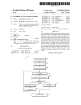
FIG. 1 is a perspective view of the portable demon
strator apparatus illustrating a preferred embodiment of
of, the electronic equipment to be demonstrated,
thereby utilizing the sense of touch.
A further object of the present invention is to incor
porate a visual display to simulate operation of the elec
tronic equipment, thereby utilizing the sense of sight.
the present invention;
FIG. 2 is an enlarged planar view of the control panel
of FIG. 1 in accordance with the present invention;
Still another object of the present invention is to
FIG. 3 is an enlarged representation of the six control
incorporate audio voice instruction in demonstrating
the operation of the electronic equipment, thereby uti
lizing the sense of hearing.
A particular objective of the present invention is to
provide an instructional “program” to sequentially
present operational procedures and information
heads of the portable demonstrator unit of FIG. 1 show
ing the location of the operator controls;
FIG. 4 is an enlarged planar view of the display panel
of FIG. 1 illustrating the format of the LED display;
FIG. 5 is a simpli?ed electrical block diagram of the
embodiment of the present invention as shown in FIG.
1;
through audio-visual means.
The present invention provides a portable audio
FIG. 6 is a detailed block diagram of the lower half of
the portable demonstrator unit of the preferred embodi
ment of the present invention; and
FIG. 7 is a detailedblock diagram of the upper half of
the portable demonstrator unit of the preferred embodi
ment of the present invention.
visual demonstration apparatus for simulating the oper
ation of particularized electronic equipment, which
includes one or more functional units, or representative
portions thereof, duplicating the specific piece of elec
tronic equipment to be demonstrated. This apparatus
comprises the combination of: an audio reproduction
device, such as a tape deck, to play pre-recorded voice
DETAILED DESCRIPTION OF THE
INVENTION
instruction; a display panel, providing' visual demonstra
The preferred embodiment of the present invention is
tion of the simulated operation in response of the elec~
directed to the application of the portable audio-visual
tronic equipment; and a portable housing, such as a 25 demonstration apparatus to communications equipment.
suitcase, containing the above elements. An instruc
In particular, the invention may be advantageously
tional “program” is provided for teaching the operation
of the electronic equipment by directing manipulations
utilized to train salesmen and customers in the features,
options, and ordering procedures of a mobile trans
ceiver unit, such as, for example the Motorola
of equipment controls through voice instruction which
cause corresponding operational responses in the visual
“MCXlOO” synthesized, microcomputer-controlled
display.
FM two-way radio. It will be appreciated, however,
that the inventive concept of the portable demonstra
The particular embodiment of the present invention is
the application of the portable demonstration apparatus
to communications equipment, speci?cally, FM two
tion apparatus is in no way limited to the mobile com
munications equipment ?eld, as other applications
way mobile radios. Six functional radio control heads, 35 could include portables, pagers, telephones, electronic
instruments, stereos, computers, or any sophisticated
representing different optional con?gurations, are pro
electronic device that warrants such demonstration.
vided along with the appropriate hand-held micro
Since the control head of the remote-mount version
phone and radio speaker. All operator controls are fully
radio contains all of the operator controls, there was no
functional to simulate a customer’s actual mobile radio
need to include the entire trunk-mounted unit in each
installation. A cassette tape player is mounted next to
portable demonstrator. Thus, six actual “MCXlOO”
the control heads to facilitate audio voice instruction.
radio control heads, of different option con?gurations,
The pre-recorded cassette tape provided with each unit
are mounted in the central portion of the lower half of
contains not only voice instruction, but inaudible tones
the demonstrator. In this particular instance, six radio
to control the display. The visual display panel is lo
cated in the upper half of the unit. A translucent plastic
sheet is placed over the display panel to format the
control heads could be con?gured to contain a majority
of all available options offered—but the actual number
of equipment units would generally depend upon the
individual application requirements. These six control
LED (Light Emitting Diode) indicators according to
the speci?c order form. All of the above elements are
contained in a medium-sized suitcase to facilitate the
portability requirement. The operational “program” is
implemented by simply following the pre-recorded
cassette tape verbal instructions describing the function
of each individual control in a logical progression. As
the operator performs the instructed control manipula
tions, the radio responds by illuminating LED’s in the
visual display; thus correlating control manipulations to
radio operation in an ordering procedure format.
50
heads are totally functional when individually selected
by the user, and they demonstrate basic radio functions
(receive, transmit, volume, squelch, channel selection,
etc.), as well as speci?c options (tone-coded squelch,
time-out-timer, channel scanning, etc.). The user physi
cally removes the microphone from the hang-up clip to
transmit, and can actually hear receiver noise in the
speaker. A tape deck is also mounted in the lower half
of the unit to play a pre-recorded cassette tape of a
BRIEF DESCRIPTION OF THE DRAWINGS
given length which instructs the user in the operation
and ordering procedures of the radio models and op
tions. The stereo cassette provided has audible voice
The features of the present invention which are be
lieved to be novel are set forth with particularity in the
and music on track one, and inaudible control tones on
track two which controls the visual display and tape
appended claims. The invention, together with the fur
counter. The tape counter is used to locate any desired
ther objects and advantages thereof, may best be under
section of the tape, and to inform the user which control
stood by reference to the following description taken in 65 head is being discussed. The upper half of the portable
connection with the accompanying drawings, in the
demonstrator contains the visual display panel, com
several ?gures of which like referenced numerals iden
tify like elements, and in which:
prised of a clear plastic window which holds one of a
plurality (in this case, six) enlarged translucent overlays
5
4,604,064
6
the scanning by pressing an active channel switch to
simulate carrier presence. In‘ either the tape deck “pro
gram” mode, or the manual mode, the control heads
appear to be fully functional—as observed by receiver
(each corresponding to a particular control head) to the
LED background. Channel selection (slaved to radio),
scan display (controlled by scan microcomputer), and
signalling options (controlled by the signalling option
noise, channel display, time-out-timer, volume control,
squelch control, microphone operation, signalling side
circuitry) are all represented by vertical columns of red
LED’s. Speci?c ordering information on each translu
cent order form is backlit by yellow LED’s, which are
controlled by the inaudible tones on the cassette tape.
Green LED’s are used to represent channel activity,
tones, and optional channel scan functions. Further
more, each portable demonstrator apparatus may be
“customized” to a particular customer’s application by
replacing PROMs, substituting different control heads,
which can be automatically controlled by the cassette
tape, or manually controlled by the active channel
switches located at the left edge of the order form.
These twelve switches allow the user to manually simu
late carrier activity on any of the radio channels to
demonstrate the channel scan options. The entire porta
ble demonstrator is housed in a medium-sized suitcase
which includes an internal power supply. The instruc
tional “program,” which is contained on the pre
recorded cassette tape, is an important feature of the
supplying new order forms, or by providing a special
cassette tape.
Some of the numerous advantages of the portable
demonstrator of the present invention are to provide:
(a) a “hands-on” training approach utilizing audio in
struction with visual feedback to simulate actual equip
ment performance; (b) a comprehensive “personalized”
instruction presented in a logical, step-by-step format;
(c) a completely self-contained portable demonstration
portable demonstrator device. The cassette “program” 20 unit being independent of a customer’s actual RF sys
tem traffic; (d) the capability to include a description of
numerous optional features on a plurality of equipment
tion presented by providing a continuous learning pro
cedure through the use of step-by-step instructions.
models; (e) a substantial amount of information in a
minimal amount of time through the use of concise
This audio instruction is organized in a logical progres
sion to explain all six control heads, starting with the 25 audio instruction; (f) a visual display of the equipment’s
internal operation to facilitate a complete understanding
easiest, i.e. carrier squelch model (control head no. 1)
of system details; (g) a basis for explaining complex
through to the most complex tone-coded squelch prior
ordering procedures through the use of a speci?c dis
ity channel scanner (control head no. 6). For example,
serves to correlate the audio, visual and tactile informa
the audio voice could instruct the user to change to
channel 12 on head no. 4, press the scan control switch,
play format; (h) a ?exible training approach through
provisions for “customizing” each individual demon
and observe the appropriate channel scanning sequence
in the display. Additionally, the cassette “program”
and demonstrating equipment capabilities.
strator; and (i) a device capable of both training a user
Referring now to the drawings, FIG. 1 is a perspec
may direct the user’s attention to a particular order
tive view of the preferred embodiment of the portable
form location, when verbally explaining the details of
that option, by illuminating the corresponding option
35
Thus, instructional information is presented to three of
the user’s senses in such a manner as to facilitate a com
plete understanding of all radio operations and ordering
procedures.
To operate the portable demonstration unit, the user
simply opens the unit, attaches the AC power cord,
switches on the AC power, plays the pre-recorded
cassette tape, and follows the speci?c “hands-on" in
structions of changing order forms and radio control
manipulations. Since each of the six translucent order
forms correlates to a particular control head, the audio
instructions will prompt the user to remove the previ
ous order form and attach the current order form before
instruction proceeds. The user is free to utilize the cas
sette deck’s fast-forward, rewind, play, stop, or pause
demonstrator apparatus 10, illustrating the application
of the present invention to a Motorola “MCXlOO” FM
two-way mobile radio. All of the elements of the dem
onstrator 10 are housed in a medium-sized suitcase 11,
number through the use of an inaudible control tone.
40
with carrying handle 12 to facilitate the hand-carried,
portability requirement. Preferably, there is an internal
AC-to-DC power supply located in the lower half of
the suitcase, with the AC power cord 17 providing the
required input voltage. If circumstances prevent the use
of an external AC line input, such as at outdoor demon
strations, then an external l2-volt DC power supply
may be connected via internal terminal posts (not
shown) furnished for such purposes. Storage compart
ment 15 accommodates the AC power cord, radio mi
crophone, and cassette tapes when the portable demon
strator 10 is not being used. Radio microphone 14 is
normally placed in the hang-up clip mounted on the
storage compartment door as shown for easy operator
access. Radio speaker 16, mounted in the lower half of
the demonstrator 10, provides an audio output for both
contains six red tape counter LED’s, one of which illu
minates whenever the tape is played, indicating which 55 the cassette tape deck and the radio audio itself. Six
totally-functional radio control heads 13 are mounted in
control head is presently being discussed. The cassette
the central portion of the lower half to allow easy ac
tape also controls the simulated carrier activity of the
cess for operator interface. A cassette tape deck 23 is
twelve channels in the visual display when demonstrat
?ush-mounted in the upper left portion of the lower half
ing speci?c channel scanning features. Additionally, the
of the suitcase 11 to facilitate the audio reproduction
portable demonstrator may be used in a manual mode to
means of operator instruction. The standard play, stop,
display radio functions for product shows, conventions,
fast forward, and rewind buttons of the cassette deck
etc. In the manual mode, the tape deck is disabled such
allow the user total control of the cassette tape. The
that the user (a salesman) may demonstrate a (custom
pre-recorded cassette tape 24 supplies verbal instruc
er’s) particular model or option. Even in the manual
mode, the display panel shows the actual radio opera 65 tions to direct the operator in each particular radio
control manipulation task, which in turn, creates the
tion by illuminating LED’s through the appropriate
desired radio response. In addition to voice instruction,
transluscent order form. The user can visualize the
the cassette tape 24 contains musical segments during
radio scanning the chosen channels, and he can control
controls to review a previously discussed option, or to
locate a speci?c section of the tape. The control panel
7
4,604,064
8
the intermission of selecting control heads and changing
order forms. Control panel 25 provides the operator
to adjust unsquelched receiver noise and signalling side
tones. Rotating the volume control completely ‘counter
with the necessary demonstrator control functions
which will subsequently be described in conjunction
clockwise turns control head no. 1 off. The channel
selector switch 48 is used to change to a desired channel
with FIG. 2. Interconnect cables 26 serve to link the
lower half of the demonstrator 10 to the upper half.
as indicated by the LED channel display 49. Transmit
indicator light 51 is illuminated whenever the micro
The display panel 18 is located in the upper half of the
suitcase to facilitate an upright display of radio func
tional operation. An enlarged translucent order form 21
microphone is out of its hand-up clip). Squelch disable
phone push-to-talk (PTT) switch is pressed (when the
is placed over the display to provide a format to assist in
switch 52 controls the radio carrier squelch operation
by muting unquieted receiver noise (when the button is
the understanding of radio ordering procedures. Nu
merous display LED’s 19, controlled by both the radio
out) or by disabling the carrier squelch mute (when the
button is depressed). The aforementioned operator con
itself and the cassette tape “program”, illuminate the
trols represent the basic radio functions common to all
display by backlighting a particular location of the
six control heads. The singletone option provides con
order form. These LED’s serve to simulate radio opera
tion, as well as orient the user to a speci?c option loca
trol head no. 1 with the singletone call button 53. When
this button is momentarily depressed, the transmit indi
tion of the order form as explained by the voice instruc
cator LED illuminates and a sidetone is heard in the
speaker.
'
tion. Active channel switches 22 allow the user the
Control head no. 2 represents the basic continuous
opportunity to simulate an active RF channel during a
channel scan demonstration. (A more detailed descrip 20 tone controlled squelch system (CTCSS) model, intro
tion of the display panel follows in conjunction with
FIG. 4.)
ducing the channel busy LED 57, the CTCSS monitor
switch 54, the selectable vCTCSS display 55, and the
selectable CTCSS button 56. These elements comprise
FIG. 2 is an enlarged planar view of the control panel
the tone-coded squelch signalling controls that are fully
25 of FIG. 1 illustrating the function of the control
panel switches. AC power switch 250 is used to turn the 25 functional.
Control head no. 3 introduces the basic six-mode
portable demonstrator off or on. The tape deck pause
switch 25b allows the user to momentarily stop the
channel scan controls andindicators which allow the
operator to simulate channel scanning operation. When
cassette tape during any part of the audio instruction
the scan-on switch 58 is depressed, the scan indicator
“program.” Tape deck volume control 25c provides an
independent volume adjustment for the cassette tape 30 LED 61 is illuminated, and the channel indicator dis
play blanks to signify channel scanning operation. Scan
audio, as distinguished from the radio receiver audio
off switch 62 returns the radio to the non-scanning
and the signalling sidetone audio. Headphone jack 25d
mode. The auxiliary control switch 59 performs addi
may be used for private instruction as required. When
tional channel increment and channel delete functions.
headphones are used, the speaker audio is muted. Scan
Control head no. 4 illustrates the six-mode channel
speed switch 25e provides an opportunity for the user to 35
scan option on a CTCSS radio model, and is primarily
slow the sequential channel scanning rate of the display
used to introduce the user to the concept of priority
LED’s such that a more comprehensive understanding
channel scanning. A variation of the channel scan op
of channel scanning features (i.e., two-level priority)
six-position rotary switch, permits the user to select one
of the-six radio control heads. When the cassette tape is
used, the pre-recorded voice will tell the user precisely
when to change to a speci?c control head, thereby
tion is shown on control head no. 5. This user-modi?a
ble option allows the user to program individual chan
nels to be scanned by means of the scan modify switch
63.
Control head no. 6 represents an extremely complex
correlating the pre-recorded instruction to each radio
combination of features and options including user
can be achieved. Control head selector switch 25}? a
model. One of the six tape counter LED’s 25g will 45 modi?able scan with two-level priority in a tone-coded
squelch radio model. The priority control switch 64
normally be illuminated whenever the cassette tape is
permits the user to alter his priority channels in addition
playing. This “electronic tape counter” informs the user
to modifying his non-priority channel scanning se
as to which radio control head is being discussed, thus
quence. Priority indicator LED’s 65 assist the user in
preventing operator confusion. During the manual
mode, whereby the cassette tape is not being played, the
priority channel scanning operation.
tape counter LED’s will not be lit. The user of the
portable demonstrator then has the freedom to select
These six control heads 13 are con?gured to repre
sent a majority of the CTCSS and channel scanning
any of the six control heads to demonstrate a particular
options offered, although additional internal features
radio model or speci?c option.
FIG. 3 identi?es the speci?c operator controls on
model being at the top. Although the six control heads
and options have not been discussed herein. It should
now be appreciated, by those skilled in the art and oth
ers, that there is an signi?cant amount of information
that must be effectively conveyed to the salesman or
customer with respect to radio operation, features, op
13 appear to be similar, each one embodies a different
tions, and ordering procedures.
model or option con?guration which must be rigor
FIG. 4 shows the display panel 18 which is mounted
in the upper portion of the suitcase 11 and connected to
the lower portion via interconnect cables 26. A thin
each of the six control heads 13. The heads are arranged
in increasing order of complexity, with the simplest
ously described to furnish the salesman with a compre
hensive understanding of radio ?exibility. All radio
controls appear totally functional to the user, through
the use of actual radio circuitry or digital logic simula
transparent plastic window 74, mounted on hinges 75,
serves to hold the translucent order form 21 to the
tion. Control head no. 1 represents a basic carrier 65
display panel. The pre-recorded voice (previously de
squelch model of the radio transceiver to be demon
strated. When this unit is selected by the control head
selector switch 25f the radio volume control 47 is used
scribed) instructs the user to turn knobs 76 and tilt the
plastic window away from the display panel to replace
order forms. A plurality of order forms are provided
4,604,064
10
This RF circuitry is not required in the portable demon
with the portable demonstrator 10 to correspond to the
six models of the control heads. Preferably, the order
form itself is an enlarged version of the actual order
strator since these functions are simulated by digital
form a salesman ?lls out when ordering a customer’s
located in the lower half, interfaces with the display via
radio. The left-most portion of the order form contains
channel frequency information and CTCSS code infor~
mation for twelve channels. (Only twelve of the thirty
two available channels are displayed.) The central por
tion of the order form contains channel scanning infor
mation, i.e., user-modi?able and six-mode channel scan
interconnect cables 26. Display control 89 serves to
decode display logic tones from the tape deck and to
interface the display to the user via the active channel
logic circuitry. Electronic equipment under display 86,
switches 22. Display logic 91 interprets the signals re
ceived from electronic equipment 86 and display con
trol 89 to provide information to display 18 in a format
that can be readily understood by the user. In the pres
assignments. The right-most portion contains ordering
ent embodiment, the display 18 consists of the red,
green, and yellow LED’s which backlight the translu
information for the channel scan, CTCSS, and time-out
timer options. This area is illuminated by yellow option
display LED’s 79 to direct the user’s attention to a
cent order form.
FIG. 6 is a detailed block diagram of the lower por
speci?c option location as determined by the cassette
tape “program.” The central portion is backlit with red
tion 82 of the preferred embodiment of the portable
scan display LED’s 78 to represent which of the twelve
demonstrator apparatus 10, and FIG. 7 is the corre
channels is presently being received, in addition to
sponding detailed block diagram of the upper portion
green mode display LED’s 73 to indicate which of the
81. In combination, FIG. 6 and FIG. 7 represent the
six scan modes is presently being utilized. Thus, a chan 20 entire detailed block diagram information of the simpli
?ed block diagram 80 of FIG. 5. Referring to the de
nel scan radio, when scanning, will typically have a
vertical row of these scan display LED’s 78 sequentially
tailed lower block diagram 100, voltage is applied to
?ashing to simulate scanning the received channels of
AC input 17 through AC switch 250 to DC power
the chosen mode. When the scan speed switch 25e
supply 84 which, in turn, supplies + 12 volts DC to the
(FIG. 2) is in the “normal” position, these flashing scan 25 radio circuitry, as well as to the interconnect and logic
circuitry. Radio 104 contains actual radio circuit
display LED’s appear to be continuously on; hence, the
“slow” scan speed position is available to reduce this
boards, such as audio 105, receiver 106, scan 107, and
signalling 108, housed in a standard radio chassis. Sche
sequential ?ashing rate for a more complete understand
matics and circuit description of these circuit boards are
ing of the scan process. If a user desires to stop the scan
available in the appropriate radio service manual. (Ra
sequence on a particular channel, he simply presses a
momentary active channel switch 22, whereby the cor
dio, Audio, Receiver, and Signalling in Motorola
responding channel display LED 72 illuminates. This
“MCXlOO” Radio Service Manual No. 68P81045E20;
and Sean in Motorola “MCXlOO” Channel Scan Sup
simulates the presence of an RF carrier on a particular
channel, which stops the channel scanner and unmutes
plement No. 68P81047E45). Accordingly, only a brief
the radio. During the automatic or “program” mode,
35
functional description is deemed necessary.
Audio circuitry 105, contained on the radio main
inaudible tones on the pre-recorded cassette also con
trol this channel activity, thus allowing a very effective
board, provides the necessary audio ampli?cation for
means of automatically demonstrating the complex
two-level priority scan option. Signalling display
LED’s 77, controlled by the radio signalling option
the tape deck, as well as for unsquelched receiver noise
and signalling sidetones. Receiver circuitry 106 con
tains actual IF and squelch circuitry to generate re
ceiver noise and interface to the scan circuitry for realis
tic channel scan simulation. Receiver quieting is simu
lated by logic control of the receiver audio gain. The
majority of scan circuitry 107 is comprised of the scan
45 microcomputer which has total control of the radio
circuitry, indicate which selectable CTCSS code has
been chosen by the user. Hence, the display panel pro—
vides the user with the unique opportunity to visualize
the intricate scanning process executed by the scan
microcomputer, as well as to be informed of the speci?c
signalling option ordering format.
channel selection process when in the scan mode. Sig
nalling circuitry 108 essentially consists of a signalling
FIG. 5 represents a simpli?ed block diagram 80 of the
board which provides CTCSS coded squelch, single
present invention as embodied by the portable demon
tone signalling, and time-out-tirner functions. PROM
strator apparatus 10 of FIG. 1. The block diagram con
circuitry 109 contains six individually-programmed
sists of an upper portion 81 representing the visual dis
scan PROM’s (such as, Motorola Part No. 51
play and a lower portion 82 containing the remaining
8007OCO1), multiplexed to the scan microcomputer and
demonstrator components. An AC power input 17 is
selected by control head switch 25f to facilitate demon
applied to the control panel 25 which supplies switched
stration of different scan options and scan mode config
AC voltage to the DC power supply 84 and the tape
deck 23. The DC power supply creates a low voltage 55 urations. Headphone jack 25d interrupts the portable
demonstrator audio to speaker 16, thereby accommo
source for the portable demonstrator components. The
dating private listening. A standard radio microphone
tape deck 23 provides audio voice instruction, tape
counter tones, as well as display logic tones. Control
14, with functioning PTT and hang-up switches, is also
panel 25 permits user interface with the portable dem
connected to the radio chassis.
onstrator, speci?cally, electronic equipment selection
and tape deck control features. Electronic equipment
60
Tape deck 23 provides voice and music through
audio circuitry 105 to speaker 16. The tape deck also
under display 86 represents one or more functional units
provides display control tones to the display logic cir
of the equipment to be demonstrated, or representative
cuitry in the upper half, as well as tape counter tones to
tape decoder 117 as displayed by tape counter LED’s
portions thereof. For example, in the present embodi
ment, the equipment consists of six radio control heads 65 25g. Display control tones may be of any appropriate
type which permit control of the required number of
13 multiplexed by the control head selector switch 25f
display indicators, and tape counter tones may be of any
to one functional radio unit from which the transmitter,
appropriate type which permit display of the desired
synthesizer, and receiver front end have been removed.
11
4,604,064
number of cassette tape sections. In the present embodi
12
?ip-?ops (such as Motorola type MCl40l3B) which
latch the active channel output. The binary coded chan
ment, the tone format on cassette tape track two is
comprised of momentary bursts of three simultaneous
“Touch-Tone” frequencies (for display control) over a
fourth continuous tone (for tape counter control). The
nel address lines from the scan microcomputer are de
coded by address decoder 138 (i.e. Motorola type
MCl45l4B four-bit latch/4-to-l6 line decoder), to facil
itate channel scanning simulation by the red scan dis
play LEDs 78. The scan detect gate 137 (for example,
three-tone burst is decoded in the upper half of the
portable demonstrator to perform thirty-two different
display control functions. The continuous tape counter
Motorola type MCl40llB NAND gates with outputs
tones are decoded in tape decoder 117, consisting of six
diode “OR’d”) accepts this decoded address informa
general purpose tone decoders, such as Signetics type 0 tion, as well as active channel information, to provide a
NE567, operating in parallel to control the tape counter
signal to the scan microcomputer to stop scanning when
LED’s 25g. One of these six tape counter tones is pres
an active channel is reached.
ent on track two of the cassette tape whenever one of
Mode latch 144 (such as Motorola type MCl4042B
the six heads is being discussed by the audio voice in
quad latch), which controls the green mode display
struction (previously described). The function of tape
LEDs 73, presents the user with a supplementary un
deck pause switch 25b and tape deck volume control
25c, which are located on the control panel 25, have
derstanding of the particular mode arrangement of the
six-mode channel scan option. Signalling decoder 146
previously been explained.
(i.e. Motorola type MCl4028B BCD~to~Decimal De
Motherboard 121 furnishes the necessary intercon
nections to multiplex the six control heads (head No. 1 20 coder) provides information to the red signalling dis
play LEDs 77 by decoding the signalling address lines
through head No. 6), via control head selector switch
from the signalling options circuitry 108. Signalling
25f to radio 104. The control head selector switch 25f
mute
gate 145 (a 12 channel><6 "control head diode
a four-pole six-position rotary switch, applies A+ and
matrix) simultaneously monitors the decoded channel
ground to each control head individually, as well as to
one of the six scan PROM’s 109. Motherboard 121, 25 address lines and the decoded signalling address lines to
create a simulated signalling mute signal to control the
primarily consists of a multitude of connectors, which
receiver audio; thereby duplicating the function of RF _
serve to distribute the appropriate voltages and signals
channel reception with valid signalling code detection.
throughout the portable demonstrator 10. It will be
Thus, even though the radio is not actually receiving an
appreciated, by those skilled in the art, that these moth
RF signal, all receiver functions (receiver quieting,
erboard interconnections are speci?c to the actual type
of electronic equipment being displayed (a radio control
tone-coded signalling detection, channel scan activity,
head in this instance). Therefore, a further detailed
etc.) appear to be fully operational to the user.
It is well known to those skilled in the art that the
explanation of the speci?c motherboard circuitry is not
deemed pertinent since the present embodiment is only
one of many alternatives.
particular implementation of the digital logic hardware,
35 electronic equipment interconnections, or other compo
nent-level circuitry is specific to this particular radio
Referring now to the detailed upper block diagram
130 of FIG. 7, interconnect cables 26 link the upper half
of the demonstrator to the lower half. Interconnect
matrix 132 serves two functions: ?rst, it contains six
mode PROM’s (i.e., Signetics type 828123) to decode
channel address information (binary) into scan display
mode information (one of six scan modes) for each of
the six control heads; secondly, it provides a wire
jumper matrix for various option con?gurations which
increase the versatility of the portable demonstrator.
transceiver embodiment of the present invention, and
hence, a further detailed description of the particular
ized component-level circuitry is not deemed necessary.
In summary, a portable audio-visual demonstration
apparatus has been disclosed for providing operational
instruction and functional simulation of particularized
electronic equipment for training and exhibition pur
45
Again, it is well known to those skilled in the art that
this scan mode display information is inherently speci?c
to the Motorola “MCXlOO” six-mode channel scan
model. Accordingly, a further detailed description is
not deemed necessary because the actual circuitry
would be different in another radio-type application.
Tone decoder 135 interfaces the inaudible display
control tone information to the display 18. In the pres
ent embodiment, the three-tone burst of display control
tones, pre-recorded on track two of the cassette tape, is
decoded and demultiplexed by tone decoder 135 using
the standard “Touch-Tone decoder” application of a
poses. The preferred embodiment of the present inven
tion is the application of the device to communications
equipment such as an FM two-way mobile radio, but it
will be apparent that the invention is not inherently
limited to the communications environment. Accord
ingly, the appended claims are intended to cover all
modi?cations and alternative variations that fall within
the true scope and spirit of the invention.
What is claimed is:
1. A portable hand-carried audio-visual demonstra
tion apparatus for simulating the operation of particu
larized radio communications equipment, said demon
stration apparatus comprising in combination:
general purpose tone decoder (such as, Signetics type
NE567) to provide one of thirty-two outputs for the
yellow option display LEDs 79 and active channel
means for controlling at least one representative por
latches 134. These active channel latches 134 illuminate
the green channel display LEDs 72 in response to either
a manual user-controlled signal from one of the twelve
visual display means, coupled to said communications
equipment control means, and including selected
active channel switches 22 or an automatic pre
recorded tape-controlled signal from tone decoder 135. 65
The active channel latches 134 consist of twelve
NAND gates (for example, Motorola type MCl40l 1B),
which “OR” these two input signals, and twelve D-type
tion of said radio communications equipment to be
demonstrated;
indicators for displaying the simulated operation of
said communications equipment in response to the
manipulation of said control means;
portable housing means for containing said communi
cations equipment control means with said display
means; and
13
4,604,064
14
further contains a cassette tape deck with a power sup
audio reproduction means for providing pre
ply requiring an AC voltage input.
recorded voice instruction in the simulated opera
12. A portable hand-carried audio-visual demonstra
tion of said communications equipment,
tion apparatus for simulating the operation of particu
whereby said voice instruction directs operator ma
nipulation of said control means which, in turn, 5 larized radio communications equipment, said demon
stration apparatus comprising in combination:
effects a corresponding operational and visual re
means for controlling at least one representative por
sponse in said display means.
tion of said radio communications equipment to be
2. The portable demonstration apparatus as described
in claim 1 wherein said radio communications equip
demonstrated;
a visual display panel, including light emitting diode
ment control means includes a plurality of representa
tive portions of said radio communications equipment
indicators coupled to said radio communications
equipment control means, for displaying the simu
lated operation of said radio communications
equipment in response to the manipulation of said
capable of demonstrating various optional con?gura
tions of said radio communications equipment.
3. The portable demonstration apparatus as described
in claim 2 wherein said optional con?gurations of said
radio communications equipment includes channel
15
scanning means.
4. The portable demonstration apparatus as described
in claim 3, wherein said visual display means includes
communications equipment; and
operator display switches for permitting manual control 20
of the visual display simulation of said channel scanning
means.
5. The portable demonstration apparatus as described
in claim 1, wherein said visual display means further
comprises:
control means;
a cassette tape deck for providing pre-recorded voice
instruction in the simulated operation of said radio
25
a display panel for providing support for said visual
display means;
light emitting diodes as selected indicators affixed to
said display panel for displaying the simulated op
eration of said radio communications equipment;
and
an overlying translucent sheet af?xed to said display
a portable suitcase for containing said radio commu
nications equipment control means with said visual
display panel with said cassette tape deck;
whereby said voice instruction directs operator ma
nipulation of said control means which, in turn,
effects a corresponding operational and visual re
sponse in said visual display panel thereby demon
strating functional capability and operational char
acteristics of said radio communications equip
ment.
13. The portable demonstration apparatus as de
scribed in claim 12, wherein said radio communications
equipment includes channel scanning means of which
the simulated operation is displayed by said light emit
panel, through which said light emitting diode
ting diode indicators coupled to said radio communica
tions equipment control means.
indicators illuminate, for providing a speci?c dis
14. The portable demonstration apparatus as de
35
play format for said visual display means.
scribed in claim 12, wherein said visual display panel
6. The portable demonstration apparatus as described
includes a plurality of overlying translucent sheets,
in claim 5, wherein said visual display means includes a
through which said light emitting diode indicators illu
plurality of said overlying translucent sheets, each of
minate, for providing a speci?c display format for said
which corresponds to a particular optional con?gura
visual display panel.
tion of said radio communication equipment.
15. A portable hand-carried, audio-visual demonstra
7. The portable demonstration apparatus as described
in claim 1, wherein said audio reproduction means fur
tion apparatus for simulating the operation of particu
ther comprises:
larized radio communications equipment, said demon
stration apparatus comprising in combination:
a plurality of representative portions of said radio
a cassette tape deck for providing audio reproduc
tion; and
a cassette tape in which voice instruction has been
pre-recorded thereon.
8. The portable demonstration apparatus as described
in claim 7 wherein said audio reproduction means fur
ther includes electronic tape counter means for decod
ing and displaying tape counter information which is
pre-recorded on said cassette tape, thereby permitting
operator to locate a speci?c portion of said cassette
tape.
9. The portable demonstration apparatus as described 55
in claim 7, wherein said audio reproduction means in
cludes display control means for decoding and display
ing display control information which has been pre
recorded on said cassette tape, thereby permitting cas
sette tape control of said visual display means.
10. The portable demonstration apparatus as de
scribed in claim 1, wherein said portable housing means
communications equipment including control
means for demonstrating function and capability of
said equipment;
control panel means for permitting operator selection
of one of said plurality of equipment control means;
power supply means for providing low voltage DC
to said equipment control means;
audio reproduction means for providing pre
recorded voice instruction in the simulated opera
tion of said equipment;
visual display means, including light emitting diode
indicators coupled to said equipment control
means, for displaying the simulated operation of
said equipment in response to the manipulation of
said control means as directed by said pre-recorded
voice instruction; and
portable housing means for containing above-stated
is a suitcase.
elements of said demonstration apparatus into a
11. The portable demonstration apparatus as de
scribed in claim 1, wherein said portable housing means 65
portable hand-carried unit.
*
1k
*
II‘
*