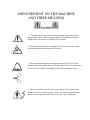
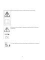
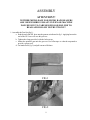
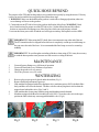
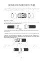
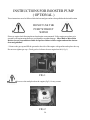
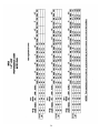
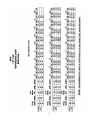
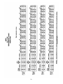
1
INTRODUCTION
Thank you for buying a Micro Rain traveling sprinkler. Please read this manual carefully before
assembling and operation, to become familiar with it’s many functions. Your safety is our first priority, and failure to follow these instructions may cause serious injury or death. Micro Rain is not
responsible for machine failure if these procedures and operation instructions are not followed.
CAUTION
z
Do not operate your Micro Rain traveler without a serious overview of this manual
z
Keep children and unauthorized people away from traveler
z
Never allow children access to use the traveler
z
Use caution when disconnecting couplings
When the traveler is equipped with shut-off valve, the supply hose remains pressurized at the end of the run.
First, relieve the pressure, then disconnect the supply hose.
z
Use caution with the sprinkler heads ( Guns )
Pressurized water from the sprinkler head could cause serious damage to people or objects.
z
Use caution during transport
Travelers are not made for public transit. Do not exceed 7mph on flat roads, or 2 mph on steep inclines.
z
Never service the traveler when it is in operation
Before servicing, stop the traveler and disconnect the supply line. All safety guards and shields must be in
place while operating the traveler.
z
Beware of power lines
Irrigation water should never contact power lines or any other power source. Never let any part of the
traveler or any irrigation pipe get in contact with power source.
1
TABLE OF CONTENTS
Signs and their meaning.....................................................3 - 4
Identification data.....................................................................5
Machine Controls.....................................................................6
Weight and Dimensions............................................................7
Transport and Assembly....................................................8 - 9
Start-Up Maintenance Procedures..................................10 - 12
Standard Hose Rewind...........................................................13
Quick Hose Rewind/Maintenance/Winterization...................14
Care and Repair of P.E. Tube.........................................15 - 16
Troubleshooting......................................................................17
Warnings.................................................................................18
Shut-Off Valve........................................................................19
Booster Pump.................................................................20 - 25
Performance Charts........................................................26 - 27
2
SIGNS PRESENT ON THE MACHINE
AND THEIR MEANING
1. This sign indicates the operations and parts that may be risky for the
safety of the operator. When seeing this sign read carefully the message
which follows, and beware of possible risk of accident.
2. This sign indicates pressurized supply lines. Do not release the clamps
before making sure that the pressure is released.
3. This sign indicates dangerous equipment in operation. Never use this
machine with safety guards removed. When using a PTO to rewind the hose,
use only protected shafts, conforming with the safety standards in force.
4. This sign indicates a risk of electric power danger. Never position the
sprinkler cart close to power supplies. Make sure that the sprinkled water
does not contact any power lines, houses, roads or any working sites.
3
5. Before operating the machine, read the instruction manual carefully.
6. Before servicing or making any adjustments stop the machine and disconnect
the supply line.
7. Do not stand between the hose reel and gun cart while machine is in operation.
4
CONDITIONS FOR MACHINE OPERATION
•
The Micro Rain machine is designed to be used with clean water suitable for irrigation. This
machine is not designed for dirty water or slurry/waste water conditions.
IDENTIFICATION DATA
The KID ID Plate includes a model number ie. MR-43, MR 58BP, and a serial number. The ID plate is
located on the left side of the machine (cover side) on the frame plate just above the rear tire.
5
MACHINE CONTROLS
1. Gearbox engage and disengage
handle.
4. Inlet shut-off valve.
2. Mechanical anchor feet
5. Speed is regulated by adjusting
the by-pass valve.
3. Automatic disengage rod.
6. Electric motor regulates by-pass
when using the optional computer
system
6
WEIGHT AND DIMENSIONS
Note: For unloading and assembly operations of the machine, use lift winches and equipment with
dimensions and capacities proportioned to the weight of the machine to be lifted. ( see tables )
DIMENSIONS (INCHES)
MR 50
MR 58
MR63
A
106
106
106
B
75
75
75
C
51
51
51
WEIGHT (LBS)
MR 50
MR58
MR63
DRY
878
875
880
WITH WATER
1396
1492
1433
7
D
64
64
64
TRANSPORT AND DELIVERY
Due to freight height and space limitations, some assembly may be required with your newly purchased
Micro Rain traveler. Be sure to follow proper procedures when unloading and assembling the machine to
avoid any danger or injury.
ATTENTION!!!
NEITHER MICRO RAIN NOR MICRO RAIN DEALERS ARE RESPONSIBLE
FOR ANY INJURY OR MACHINE FAILURE DUE TO LACK OF PROPER
SAFETY PROCEDURES OR FAILURE TO READ AND FOLLOW
INSTRUCTIONS.
1)
Micro Rain travelers are either shipped on a special skid (partially disassembled) which can be un
loaded with a fork lift, or they are shipped in a fully assembled state by blocking on the shipping floor.
2)
The proper procedure to unload the skid shipment is with a fork lift or equivalent.
Standard packaging and pallet shipping for Micro Rain travelers.
8
ASSEMBLY
ATTENTION!!!
NEITHER MICRO RAIN NOR MICRO RAIN DEALERS
ARE RESPONSIBLE FOR ANY INJURY OR MACHINE
FAILURE DUE TO CARELESSNESS OR FAILURE TO
READ AND FOLLOW INSTRUCTIONS!!!
1. Assemble the Gun Cart (fig 1 ).
a. Push the end of the P.E. hose onto the guncart as indicated in fig 1. Applying heat to the
end of the P.E. hose will ease this process.
b. Tighten the clamp provided, with the bolts on top.
c. Mount the sprinkler gun onto the gun cart. Use teflon tape or a thread compound to
provide a proper seal.
d. Use hand wheel ( fig 2 ) and pull cart on to lift frame.
FIG 1
FIG 2
9
CHECKING MACHINE
BEFORE START UP
( CHECK-LIST )
1. Check the oil level of the gearbox and if necessary add SAE 80W/90. Keep oil level above the side
plugs in the gearbox in order to bathe the shift fork in oil.
2. Grease the machine thoroughly (all grease fittings) and thereafter, grease every 100 hours.
( see fig 1 ). Pay close attention to the two grease fittings on the drum inlet. One grease fitting is located
on the bottom side and lubricates the drum inlet seals. Grease must be spread on the drum gear teeth
and at the drive shaft where the drum gear and drive gear mesh. The scroll bar must also be kept well
greased, and the scroll knife must be lubricated (grease fitting) in order to function correctly.
3. Check the tire pressure and if necessary, inflate to pressure recommended on the tire (generally 35psi).
FIG 1
LUBRICANT TABLE
Gearbox
Reel Supports
Grease Fittings
SAE 80W/90
Grease NLGI No. 2
Grease NLGI No. 2
10
START UP PROCEDURE
1. Tow the machine to the working site (off-road only). Maximum speed is 7 MPH. WARNING!!
Before towing machine, make sure the gun cart is racked.
2. Face the gun cart side of the reel towards the area needing to be irrigated. The machine direction
should be as straight as possible.
FIG 1
FIG 2
FIG 3
3.
4.
5.
6.
Set the front stabilizer ( fig 1 ).
Release the backstop (anti-reverse) lever.(Fig 2) Pull straight back and down.
Lower cart by lifting on cart lever and slightly lifting on cart to release from the latch mechanism. (fig 3)
Connect the water supply hose to the water inlet connection on the machine ( fig 4 ).
NOTE: Before connecting the supply hose to the machine, flush out hose or check to be sure
there is no foreign matter which will block the turbine.
.
7. Important!
Make sure the gearbox lever is in the disengaged or idle position before unwinding
tube ( fig 5 ).
FIG 4
FIG 5
11
FIG 5
FIG 6
8. Pull the gun cart out straight ( fig 5 ), and at a consistent speed ( about the pace of a walk ), and
slow down when approaching the stop or end position. NOTE: Always leave at least one wrap of
hose on the reel.
9. Remove assist handle from holder and use to pull shut-off valve into the open position (fig 6)
10.Re-engage anti-reverse handle (fig 3) and start water flow. Adjust speed control valve to the fast setting
(slide adjustment rod to the left) (fig 7) and engage gearbox. Move the speed control rod back to
the right to slow reel to the desired speed. If computer speed control system see page 15 for specific
instructions on operation.
11.When you have pulled out the hose make sure that the wraps remaining on the reel are close
together. If necessary push them in place by hand. ( fig 8 ). This adjustment must be done
when machine is not in operation.
IMPORTANT! The first time using the machine it is very important to pull out all but 1 or 2
wraps of hose in order to check the level wind setting, and remove any loose wraps that may
have been created in shipping. If level wind setting needs adjusting, contact your Micro Rain
dealer for instructions.
FIG 7
12
FIG 8
STANDARD HOSE REWIND
(Ready to rewind hose for irrigation)
1. Engage the back stop ( anti-reverse ) ( fig 1 ) into the operating position by gently lifting handle until it
releases from the lock position. Note: On older units the anti-reverse is located under the hood. To
actuate, the chain is pulled down torelease.
FIG 1
FIG 2
2. Turn the water supply on and increase the machine pressure until it reaches the desired operating
pressure. Make sure shut-off valve is in the open position (Page 12 fig 6).
3. Engage the gearbox with the gearbox handle (fig 2 ), to put the reel into rewind motion.
IMPORTANT!!! Never force this lever into gear. Forcing into gear will irrrevocably damage the
gearbox and void the warranty. Lever should be pushed gently into gear, allowing the gears to
mesh. This process is best completed with water running through the turbine.
4. Adjust hose retraction speed. On a manual speed control machine, this is completed by adjusting the
position of the bypass valve (fig 3). Full reel speed is achieved with the speed control rod moved
completely to the left. To slow the retraction speed, slowly slide the speed control rod back to the right
until the desired retraction speed is obtained. On computer speed control machines, speed is adjusted
by entering the desired retraction rate (in ft/hour) on the computer key pad.(fig 4) The speed can be
adjusted any time during operation by using the + or - buttons on the key pad. See the Golden Rain
manual for specific instructions concerning the computer setting/operation.
FIG 3
FIG 4
13
QUICK HOSE REWIND
The purpose of the PTO shaft on the gearbox is to rewind the hose quickly by using the tractor. If for any
reason you need to wind the hose up quickly then follow these steps.
1. WARNING! Make sure the handle on the gearbox is in the idle or disengaged position, otherwise
severe damage will occur to the gearbox.
2. Connect the tractor PTO drive line to the gearbox shaft on the Micro Rain. WARNING! Read
drive-line directions for proper use of the PTO drive-line. Neither Micro Rain nor Micro Rain
dealers are responsible for improper use of the drive line which can result in injury or death.
3. Activate the tractor power take off and the reel will begin to wind up. Roll up hose at a slow RPM
IMPORTANT!! When using the PTO shaft, there is no automatic stop at the end of the run.
The PTO must therefore be stopped before the hose is completely wound up to avoid damage to
the gun cart or the end of the hose. It is recommended the final wrap or two to be wound up
manually.
IMPORTANT!! To avoid irregular rewinding of the hose when using a PTO, it may be necessary
to wind the hose up under water pressure to avoid excessive ovaling of the hose.
MAINTENANCE
1.
2.
3.
4.
Grease all grease fittings every 100 hours of operation.
Grease all wheel hubs every 100 hours of operation.
Change the gearbox oil every season.
Check tire pressure every 4-6 weeks.
WINTERIZING
1.
2.
3.
4.
5.
Remove plug or open petcock placed under the turbine ( Fig 1 ).
Remove drain plug on bottom of gun cart.
If the machine is equipped with a blue diaphram valve ( machines prior to 2003), the black filter
body, and blue valve must be drained. The blue valve has a brass plug that is used to drain the
trapped water behind the valve.( Figs 2 and 3)
If the machine has a boost pump, then the pump and plumbing must be drained.
Machines equipped with the new inlet shut-off valve (2003 - ) must leave the valve in the open
position in order to drain any water trapped behind the valve.( Fig 4)
Fig 1
Fig 2
Fig 3
14
Fig 4
CARE OF THE POLYETHYLENE TUBE
The polyethylene tube ( P. E. Tube ) is a very durable and will serve your irrigation needs for many
years with proper care and handling. Observe these simple precautions when using your Micro Rain
traveler to prevent damaging or shortening the life of your tube.
1. The first time you unwind the tube, pull off all but a couple of wraps. This will allow you to check
the level-wind position, and make sure there are no loose wraps left from shipping.
2. Always transport your machine with the anti-reverse lever engaged, and the cart racked.
3. Do not attempt to operate the machine with loose or misplaced wraps of tube. Tighten the tube
on the drum before starting the machine. WARNING!! Starting the machine without tightening the
tube wraps will result in miswrapping and could permanently damage your tube.
4. Do not attempt to move or relocate the machine with tube unwound. All the tube must be wound
on the machine drum before moving.
5. While the tube is unwound make certain never to drive anything across the tube.
6. Be careful when operating other equipment near the unwound tube.
7. Never sharply bend or kink the tube. It will not flex back, and it will be permanently damaged.
15
REPAIR COUPLER FOR P.E. TUBE
Screw-in menders are the best way to repair damaged P. E. tube in the field. These metal menders
will allow you to repair damaged tube without replacing the entire length of tube. These tube menders can be obtained from your Micro Rain dealer.
INSTALLATION
1. Cut the tube with a hack-saw on either side of the damaged area. Make sure your cuts are straight.
Place expansion collar over each end of tube ( fig 1 ).
FIG 1
2. Chamfer the inside and outside of the tube with a knife or file, so that the threads of the metal mender
will enter the tube.
3. NOTE!! The threads on the metal mender are lefthand threads on one end and righthand threads
on the other. Screw the mender in one end about 2/3 of the way using a wrench. Then unscrew it.
Repeat the procedure on the other end. Remember one end is left-hand thread. Do not apply heat to
the tube during this procedure ( fig 2 ).
FIG 2
4. Complete the procedure by starting the threads in both ends at the same time, turning the mender
with a wrench. Screw the mender all the way into the tube until the two ends meet and are snug
(fig 3).
FIG 3
16
TROUBLESHOOTING
HOSE DOES NOT WIND UP
* The impeller of the turbine is blocked by foreign matter. Solution- Remove the turbine cover and clean
the housing.
* The gun is partly clogged and only a small amount of Solution- Proceed to clean out gun nozzle.
water comes out.
* The injection nozzle in the turbine is clogged.
Solution- Disassemble the hose at the turbine
entry and clean out.
* The gun nozzle is too small, compared to the machine . Solution- Replace with a larger gun nozzle or a
model.
smaller injection nozzle.
* Not enough water volume or pressure at the machine Solution- Increase volume and/or pressure.
inlet.
* The gearbox has been damaged.
Solution- Repair the gearbox.
MACHINE WON’T STAY ANCHORED OR SLIDES
* The machine legs are improperly placed.
Solution- Reposition leg to create more friction.
* The hose is on damp soil or grass which produces too Solution- Wait until the soil has dried or pick up
much drag.
hose and place blocks of wood under
in order to reduce friction.
RECOMMENDATIONS
* When moving the machine never exceed the maximum speed of 7 MPH.
* If the hose is wound up using the PTO, be certain the gearbox is in the idle or disengaged position, or the
gearbox will be seriously damaged.
* At the beginning of each season, completely unwind the hose, leaving only two wraps on the reel.
* ANY MODIFICATION MADE TO ANY PART OF THE MACHINE WILL VOID THE
WARRANTY.
* If the hose remains unwound on the ground for an extended period of time ( several hours ), it may stick
to the ground. Prior to starting the machine, take a rope and drag underneath the tube from one end to
the other, avoiding any damage due to too much friction.
* If the machine is being used on several short fields, the hose may miswrap, or not continue to roll up
correctly. If this happens, unwind the hose with only two wraps remaining on the drum, allowing the
machine to rewind properly.
* THE MACHINE MUST NOT BE OPERATED WITH OUT THE PROTECTION GUARDS
* IMPORTANT!! Failure to observe these instructions, the use of non original spare parts, or
unauthorized changes to the machine will void the warranty.
17
WARNINGS AND RISKS
MICRO RAIN AND MICRO RAIN DEALERS ARE NOT
RESPONSIBLE FOR ANY INJURY OR DAMAGE DONE
DUE TO FAILURE TO FOLLOW SAFETY GUIDELINES
Despite Micro Rain’s attempt to a make a safe and secure machine, some risks still remain un
avoidable in the operation of the machine. Failure to heed these warnings can cause serious
injury or death.
When pulling out the hose no one should be standing on or around the machine unless authorized to
do so.
No part of the body should ever be between the hose and the reel when the machine is in use. This
applies especially to unauthorized people.
When the machine is being transported on a grade of 6 degrees or greater, there is a risk of the
machine overturning. Take every precaution to avoid transporting on steep grades.
Make sure that in the rain gun ( sprinkler head ) path of irrigation there are no electrical wires or
power lines.
Tremendous water pressure comes through the hose to the gun. Avoid standing by or near the
direction of the sprinkler gun.
Never remove the quick connect couplings on the machine while water pressure is being supplied to
the machine.
Be very careful when transporting the machine. Use safety measures when towing. When irrigating
be sure sprinkler head is not pointing toward objects or individuals unaware of the powerful jetstream.
18
SHUT-OFF VALVE
1. In order for water to enter the machine, the shut-off valve must be manually opened prior to irrigating.
Remove the assist handle from the holder and place in the valve arm (fig 1).
2. Pull valve open using the assist handle. The valve will latch and hold in the open position (fig 2) Note: The
latching mechanism occurs automatically when the tube rider is below the first wrap.
3. The adjustment for the valve latch is located between the gear shift rod and the speed control rod (fig 3)
Loosen the set screws in the stop block, and adjust rod position in order to time shut-off with cart loading. The
shut-off valve should actuate just prior to the gearbox being shifted to the neutral position at the transit position.
(fig 4)
FIG 1
FIG 2
FIG 3
4) The shut-off action takes place as the cart is loaded on the cart frame and locked into transit position.(fig 4)
This is the position in which the cart is re-lowered in order to complete another irrigation run. Prior to pulling
out the cart for another run, it is extremely important the gearbox is in the idle or neutral position.
Once the cart is loaded in the transit position, the gearbox should be automatically shifted in the
neutral position (Shift handle to the far left position). (fig 5) If the cart is pulled out with the gearbox
engaged, it will severely damage the gearbox.
FIG 4
FIG 5
19
INSTRUCTIONS FOR BOOSTER PUMP
( OPTIONAL )
These instructions are to be followed after the hose and gun cart have been pulled to the desired location.
DO NOT USE THE
PUMP WITHOUT
WATER
Please see engine check list using the enclosed engine owners manual. Follow engine procedures as instructed by the engine manufacturer to avoid pump or machine damage. Micro Rain or Micro Rain
Dealers are not responsible nor liable for operator failure to follow engine and machine instructions and guidelines.
* Remove the gas cap and fill the gas tank to the side of the engine with gasoline and replace the cap.
Do not over-tighten gas cap. Check gas level often to be sure engine has fuel ( fig 1 ).
FIG 1
Never use the tank placed on the engine (fig 2 ) for any reason.
FIG 2
20
* Connect the water supply hose to the quick connect fitting ( fig 3 ) on the machine.
FIG 3
* If your machine has a shut-off valve ( fig 4 ), make sure the valve is in the open position.
FIG 4
* Turn on the water source and pressure to the machine.
21
ENGINE START-UP
NOTE: The engine will not start without water flowing through the machine!
* Turn on the gas switch as indicated in fig 5.
FIG 5
* If the engine is cold, “choke” the engine by pushing the switch to the left ( fig 6 ).
FIG 6
* Start the engine by pulling on starter rope (Fig 7), or by turning ignition key clockwise (Fig 8)
FIG 8
FIG 7
22
* Set the choke to a smooth working position by moving the lever to the right.
* Increase engine speed until the desired working pressure is obtained.
WARNING!! Do not exceed the maximum working pressure of 120 psi, at the gauge on
the cross pipe (boost pump models).
* STOPPING AT THE END OF RUN: When the gun cart arrives at the machine at the end of the run,
it activates the shut-off valve. When the valve is closed, the flow switch mounted on the water inlet ( fig 8 )
senses the loss of water flow and automatically kills the engine.
Note: Water should always be running through the pump prior to starting boost pump, but if for some reason
the pump must be started without water flow (for short duration), the by-pass button can be pressed to override the flow switch located on the engine mount bracket. (Fig 9) Again, the pump must not be run for more
that 5 seconds without water to lubricate the mechanical seal.
FIG 8
FIG 9
23
FORBIDDEN USES
WARNING
DO NOT USE THIS MACHINE IN
A NON-VENTILATED AREA
1. Do not use this machine with solids, waste, etc. This machine is designed only for use in clean water
applications.
2. Do not use in high risk areas for explosives.
3. Do not use in enclosed areas.
OPERATION AND MAINTENANCE
1. Check oil level prior to each operation, and change oil as recommended (Refer to Honda Owners
Manual).
2. Follow environmental regulations when disposing of old parts or oil.
3. Regular maintenance and repairs must be performed by a trained professional operator.
4. Any and all repairs and maintenance must be performed when the engine is turned off and cooled down.
FIRE EMERGENCY
1. In case of fire use a powder fire extinguisher.
BATTERY INSTRUCTIONS AND USE
1. The electrolyte is a diluted sulfuric acid solution. In case of contact with skin, wash immediately!!
Contact medical help immediately if solution gets in your eyes. WARNING!! When recharging any
battery, a flammable gas is produced which could cause battery to explode.
2. Avoid sparks when attaching or charging battery. Verify correct cable placement. Verify that battery
cables are placed correctly when recharging the battery ( + with +, - with - ). Keep away from
matches, cigarettes or any flammable objects. Do not rest metal tools on the battery.
3. Keep children away from the battery! Periodically verify the battery charge. During the off season,
remove the battery and keep it in a warm, dry location and recharge as necessary.
24
WARNINGS FOR POTENTIAL RISKS
1. WARNING!! Never exceed the maximum operating pressure of 120 psi. Monitor the pressure gauge
on the machine inlet. Extreme high pressure may cause product failure and result in serious injury.
2. WARNING!! During operation of machine, stay away from parts which experience high temperature
such as the muffler, manifold, etc., which may burn or cause serious injury.
3. WARNING!! Do not get close to moving parts nor high temperature parts to avoid danger or serious
injury.
TROUBLESHOOTING ENGINE and BOOSTER PUMP
THE ENGINE DOES NOT START
* The machine does not have water pressure. The flow safety switch will not allow the engine to start with
water running through the machine.
* A closed shut-off valve.
Solution- Make sure the handle is in the open for operation (Fig 1)
* Flow switch is malfunctioning.
Solution- Remove switch and check contacts and wiring. Replace
if necessary. (Fig 2)
FIG 1
FIG 2
* Check oil level. If oil level is below required level, the engine will not start.
* Check to be sure fuel is getting to the engine. Open the carbuerator drain to check for fuel.
PUMP IS LEAKING
* Replace the mechanical seal inside the pump.
PUMP IS NOT BUILDING PRESSURE
* Check the impeller in the pump. It could be clogged or broken.
25
26
27
28
29