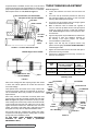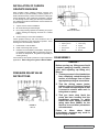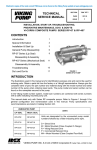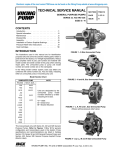
1
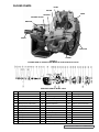
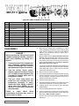
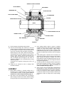
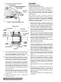
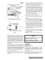
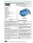
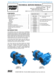
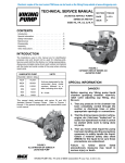
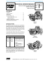
Place pair of half round rings on shaft and slide inner
bearing spacer collar over half round rings to lock them
in place. There is no pair of half round rings on Q, QS
and M size pumps. Refer to Figure 7, page 8.
right side
of pump
seal access hole (for setscrews)
spring adapter
mechanical seal (Rotary member)
seal seat gasket
seal holder
seal
holder
plate
set collar
seal
seat
FIGURE 8 - standard mechanical seal
spring
mechanical seal
(rotary member)
9. Press lip seal, lip facing end of shaft, in inner end cap
and insert end cap through shaft end of bracket. Turn
end cap clockwise, looking at shaft end, until it engages
threads. End cap spanner wrench holes must be facing
rotor. Turn end cap with spanner wrench until it projects
slightly from opening on side of bracket. End cap must
not be turned so far that lip seal drops off end of spacer
collar on shaft or end cap becomes disengaged from
threads. Refer to Figure 7, page 8.
If this happens, remove inner spacer collar, half round
rings and end cap and start over at Step 8.
10.Pack ball bearing with multi-purpose grease, NLGI
#2. Place on shaft and push or gently drive in place in
bracket.
11. Press lip seal, lip facing end of shaft, in outer end cap
and insert end cap in bracket. Turn end cap in bracket
until it is tight against bearing. Refer to Figure 7, page 8.
12. Put lockwasher and locknut on shaft. Insert length of
hardwood or brass through port opening between rotor
teeth to keep shaft from turning. Tighten locknut to 120150 ft.– lbs. Torque (LS) or 170-190 ft. – lbs. Torque (Q,
QS, M). Bend one tang of lockwasher into slot of locknut.
If tang does not line up with slot, tighten locknut until it
does. Failure to tighten locknut or engage lockwasher
tang could result in early bearing failure and cause
damage to rest of pump.
tapered sleeve
coat with light oil before assembly
FIGURE 9
7. Install rotating member of seal. Slide spring over shaft
into seal chamber and onto set collar pilot. Center spring
adapter (Q, QS and M size only) against back of metal
retainer so spring will push against adapter and not work
itself over back of mechanical seal. Place tapered sleeve
on shaft. Refer to Figure 9. Apply a liberal coating of
SAE-30 non-detergent oil to large diameter portion of
shaft, tapered sleeve and to inside diameter of seal
rubber parts. Start rotary member, carbon face out,
onto shaft and push along shaft until spring is centered
against adapter.
Install Stationary Seal Seat. Lubricate outside diameter
of seal o-ring seat gasket and flush lapped face with lube
oil. Press stationary seat into bore until lapped face is
just inside bore. Position stationary seat by installing seal
holder and secure to machined face of bracket with seal
holder plate. Tighten nuts securing seal holder evenly so
seal holder will not be distorted. Refer to Figure 8.
Remove tapered installation sleeve.
8. Slide inner spacer collar over shaft with recessed end
facing rotor. Q, QS and M size bearing spacer collars are
not recessed.
Remove length of hardwood or brass from port opening.
13. Adjust pump end clearance. Refer to Thrust Bearing
Adjustment, page 10.
14. Lubricate all grease fittings with multi-purpose grease,
NLGI #2.
DANGER !
Before starting pump, be sure all drive
equipment guards are in place.
Failure to properly mount guards may
result in serious injury or death.
ASSEMBLY
Optional Mechanical Seal
(PTFE Fitted Type)
The seal type shown in Figure 10, page 10 can be installed
as an alternate to the standard mechanical seal (synthetic
rubber bellows type). This seal is setscrew driven, is simple
to install and good performance will result if care is taken
during installation.
Clean rotor shaft and seal housing bore. Make sure they are
free of dirt, grit and scratches. Gently radius leading edge of
shaft diameter over which seal is to be placed.
SECTION TSM 141.2
ISSUE
F
PAGE 9 OF 12