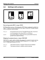
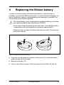
1
System Board D2559
for TX150 S6
Technical Manual
Edition June 2009
Comments… Suggestions… Corrections…
The User Documentation Department would like to
know your opinion of this manual. Your feedback helps
us optimize our documentation to suit your individual
needs.
Feel free to send us your comments by e-mail to
[email protected].
Certified documentation
according to DIN EN ISO 9001:2000
To ensure a consistently high quality standard and
user-friendliness, this documentation was created to
meet the regulations of a quality management system
which complies with the requirements of the standard
DIN EN ISO 9001:2000.
cognitas. Gesellschaft für Technik-Dokumentation mbH
www.cognitas.de
Copyright and Trademarks
Copyright © 2009 Fujitsu Technology Solutions GmbH.
All rights reserved.
Delivery subject to availability; right of technical modifications reserved.
All hardware and software names used are trademarks of their respective manufacturers.
Contents
1
Introduction . . . . . . . . . . . . . . . . . . . . . . . . . . . . 5
2
Important notes . . . . . . . . . . . . . . . . . . . . . . . . . . 7
2.1
Notes on safety . . . . . . . . . . . . . . . . . . . . . . . . . . 7
2.2
CE Certificate . . . . . . . . . . . . . . . . . . . . . . . . . . 10
2.3
Environmental Protection . . . . . . . . . . . . . . . . . . . 11
3
Features . . . . . . . . . . . . . . . . . . . . . . . . . . . . . 13
3.1
Overview . . . . . . . . . . . . . . . . . . . . . . . . . . . . 13
3.2
Main memory . . . . . . . . . . . . . . . . . . . . . . . . . . 16
3.3
PCI bus . . . . . . . . . . . . . . . . . . . . . . . . . . . . . 18
3.4
Screen resolution
3.5
Temperature / system monitoring . . . . . . . . . . . . . . . 20
3.6
LEDs . . . . . . . . . . . . . . . . . . . . . . . . . . . . . . . 22
3.7
3.7.1
Interfaces and connectors . . . . . . . . . . . . . . . . . . . 24
External ports . . . . . . . . . . . . . . . . . . . . . . . . . . 25
3.8
Settings with jumpers . . . . . . . . . . . . . . . . . . . . . 28
4
Replacing the lithium battery . . . . . . . . . . . . . . . . . 29
. . . . . . . . . . . . . . . . . . . . . . . 20
Abbreviations . . . . . . . . . . . . . . . . . . . . . . . . . . . . . . . 31
D2559 (TX150 S6)
Technical Manual
1
Introduction
This technical manual describes the system board D2559, which is equipped
with one Intel® processor.
Further information about drivers is provided in the readme files on the hard
disk, on the supplied “ServerStart“ or “Update“ CDs.
You will find further information in the BIOS description.
Notational conventions
The meanings of the symbols and fonts used in this manual are as follows:
italics
indicates commands, menu items, file and path
names or software programs
fixed font
indicate system output on the monitor
semi-bold fixed
font
indicates values to be entered through the keyboard
[Key symbol]
indicates keys according to their representation on the
keyboard
If capital letters are to be entered explicitly, then the
Shift key is shown, e.g. [SHIFT] - [A] for A.
If two keys need to be pressed at the same time, then
this is shown by placing a hyphen between the two key
symbols.
“quotation marks”
indicates names and terms that are being emphasized.
Ê
indicates an operation that to be performed
V CAUTION!
I
indicates warnings, which, if ignored, will endanger
your health, destroy the system or lead to the loss of
data.
indicates additional information, notes and tips
Table 1: Notational conventions
D2559 (TX150 S6)
Technical Manual
5
2
Important notes
In this chapter you will find essential information regarding safety when working
with your server.
V CAUTION!
With the system board installed you must open the system to access the
system board. How to access the system board of your system is
described in the appropriate service supplement.
When handling the system board, refer to the specific notes on safety in
the operating manual and/or service supplement for the respective
server.
2.1
Notes on safety
V CAUTION!
●
The actions described in these instructions should only be performed
by authorized, qualified personnel. Equipment repairs should only be
performed by qualified staff. Any failure to observe the guidelines in
this manual, and any unauthorized openings and improper repairs
could expose the user to risks (electric shock, fire hazards) and could
also damage the equipment. Please note that any unauthorized
openings of the device will result in the invalidation of the warranty
and exclusion from all liability.
●
Transport the device only in the antistatic original packaging or in
packaging that protects it from knocks and jolts.
●
Only install expansions that are allowed for the system board. If you
install other expansions, you may damage the requirements and rules
governing safety and electromagnetic compatibility or your system.
Information on which system expansions are suitable can be
obtained from the customer service centre or your sales outlet.
●
The warranty expires if the device is damaged during the installation
or replacement of system expansions.
D2559 (TX150 S6)
Technical Manual
7
Notes on safety
V
Important notes
●
Components can become very hot during operation. Ensure you do
not touch components when making extensions to the system board.
There is a danger of burns!.
●
Transmission lines to peripheral devices must be adequately
shielded.
●
To the LAN wiring the requirements apply in accordance with the
standards EN 50173 and EN 50174-1/2. As minimum requirement
the use of a protected LAN line of category 5 for 10/100 MBps
Ethernet, and/or of category 5e for Gigabit Ethernet is considered.
The requirements of the specification ISO/IEC 11801 are to be
considered.
●
Never connect or disconnect data transmission lines during a storm
(lightning hazard).
Batteries
V CAUTION!
●
Incorrect replacement of lithium battery may lead to a risk of
explosion. The batteries may only be replaced with identical batteries
or with a type recommended by the manufacturer.
It is essential to observe the instructions in chapter “Replacing the
lithium battery”.
8
Technical Manual
D2559 (TX150 S6)
Important notes
Notes on safety
Modules with electrostatic-sensitive components
Systems and components that might be damaged by electrostatic discharge
(ESD) are marked with the following label:
Figure 1: ESD label
When you handle components fitted with ESDs, you must observe the following
points under all circumstances:
●
You must always discharge yourself of static charges (e.g. by touching a
grounded object) before working.
●
The equipment and tools you use must be free of static charges.
●
Remove the power plug from the power socket before inserting or removing
boards containing ESDs.
●
Always hold boards with ESDs by their edges.
●
Never touch pins or conductors on boards fitted with ESDs.
●
Use a grounding cable designed for this purpose to connect yourself to the
system unit as you install/deinstall the board.
●
Place all components on a static-safe base.
I You will find a detailed description for handling ESD components in the
relevant European or international standards (EN 61340-5-1,
ANSI/ESD S20.20).
D2559 (TX150 S6)
Technical Manual
9
CE Certificate
Important notes
Notes about boards
●
During installation/deinstallation of the system board, observe the specific
instructions described in the service manual for the server.
●
Remove the plug from the mains outlet so that system and system board are
totally disconnected from the mains voltage.
●
To prevent damage to the system board, the components and conductors on
it, please take great care when you insert or remove boards. Take great care
to ensure that extension boards are slotted in straight, without damaging
components or conductors on the system board, or any other components,
for example EMI spring contacts
●
Be careful with the locking mechanisms (catches, centring pins etc.) when
you replace the system board or components on it, for example memory
modules or processors.
●
Never use sharp objects (screwdrivers) for leverage.
2.2
CE Certificate
The shipped version of this board complies with the requirements
of the EEC directive 89/336/EEC "Electromagnetic compatibility".
Compliance was tested in a typical PRIMERGY configuration.
10
Technical Manual
D2559 (TX150 S6)
Important notes
2.3
Environmental Protection
Environmental Protection
Environmentally friendly product design and development
This product has been designed in accordance with standards for ”environmentally friendly product design and development“. This means that the designers
have taken into account important criteria such as durability, selection of
materials and coding, emissions, packaging, the ease with which the product
can be dismantled and the extent to which it can be recycled.
This saves resources and thus reduces the harm done to the environment.
Notes on saving energy
Devices that do not have to be on permanently should not be switched on until
they need to be used and should be switched off during long breaks and on
completion of work.
Notes on packaging
Please do not throw away the packaging. We recommend that you do not throw
away the original packaging in case you need it later for transporting.
Notes on dealing with consumables
Please dispose batteries in accordance with local government regulations.
Do not throw batteries and accumulators into the household waste. They must
be disposed of in accordance with local regulations concerning special waste.
All batteries containing pollutants are marked with a symbol (a crossed-out
rubbish bin on wheels). In addition, the marking is provided with the chemical
symbol of the heavy metal decisive for the classification as a pollutant:
Cd Cadmium
Hg Mercury
Pb Lead
Notes on labeling plastic housing parts
Please avoid attaching your own labels to plastic housing parts wherever
possible, since this makes it difficult to recycle them.
D2559 (TX150 S6)
Technical Manual
11
Environmental Protection
Important notes
Returning, recycling and disposal
The device may not be disposed of with household rubbish. This
appliance is labelled in accordance with European Directive
2002/96/EC concerning used electrical and electronic appliances
(waste electrical and electronic equipment - WEEE).
The guideline determines the framework for the return and recycling
of used appliances as applicable throughout the EU. To return your
used device, please use the return and collection systems available
to you. You will find further information on this at
http://ts.fujitsu.com/recycling.
For details on returning and reuse of devices and consumables within Europe,
refer to the “Returning used devices” manual, or contact your Fujitsu Technology
Solutions branch office/subsidiary or our recycling centre in Paderborn:
Fujitsu Technology Solution
Recycling Center
D-33106 Paderborn
Tel.
+49 5251 8 18010
Fax
+49 5251 8 18015
12
Technical Manual
D2559 (TX150 S6)
3
Features
3.1
Overview
Processor
– one Intel® Xeon™ processor
– processor socket LGA775 for Intel® Xeon™ processor with 800, 1066 or
1333 MHz Front Side Bus
Main memory
– four slots for main memory DDR2 667/800 MHz (unbuffered),
SDRAM memory modules with 256 MB up to 4 Gbyte
– maximum 16 Gbyte of memory
– minimum 256 MB
– ECC multiple bit error detection and single bit error correction
Chips on the system board
Intel® 3210 MCH north bridge
Intel® ICH9R south bridge
GBit LAN controller (Broadcom BCM5755T)
Super-I/O controller (SMSC SCH5027)
Flash EPROM for:
– local BIOS update via bootable USB device or optional floppy disk
– remote BIOS update via LAN
– iRMC chipset with integrated VGA graphic controller
– ADM7462 thermal system management controller
–
–
–
–
–
External connectors
–
–
–
–
–
–
–
–
4x UHCI USB 2.0
serial port (COM1)
serial port (COM2) (optional)
parallel port (optional)
2x PS/2 ports for keyboard and mouse
VGA
RJ45 LAN
RJ45 Service LAN
D2559 (TX150 S6)
Technical Manual
13
Overview
Features
Internal connectors
– dual USB 2.0
– SATA (1-4) multilane
– 2x SATA
– floppy disk
– SAS/SATA/HD Activity LED
– front panel
– CPU fan 4 pins
– system fan 4 pins
– 4x system fans 5 pins
– PC98
– power (12V, -12V, 5V, 3.3V and 5V auxiliary)
– 12V (CPU) power
– intrusion detection
– SMB
PCI slots
– 3 x PCI (32 Bit / 33 MHz)
– 2 x PCI Express x8
– 1 x PCI Express x4
BIOS features
–
–
–
–
–
–
–
–
Phoenix System BIOS V 6.00
SMBIOS 2.34 (DMI)
MultiProcessor specification 1.4
Server Hardware Design Guide 3.0
WfM 2.0
ACPI 1.0b support with extensions from ACPI 2.0/3.0
USB keyboard/mouse
boot possible from:
– 120 MB floppy disk drive or USB floppy disk drive
– CD-ROM
– USB 2.0 devices
– LAN
– no Alert on LAN
– console redirection support
– OEM logo
– memory disable
14
Technical Manual
D2559 (TX150 S6)
Features
Overview
Environmental protection
Battery in holder for recycling
Form factor, slot compatibility list
– ATX dimension: 305 mm x 244 mm
– ACPI 1.0b, OnNow, PCI 2.3, PCI Express 1.0a, WfM 2.0, SHDG 3.0,
MPS 1.4, IPMI 2.0, PCI SHPC 1.0, USB2.0
CSS (Customer Self Service)
This system board supports the CSS functionality. You will find a description of
CSS functionality in the operating manual of your server.
TPM (option)
The system board is optional equipped with a TPM (Trusted Platform Module)
by the manufacturer. This module enables programs from third party manufacturers to store key information (e.g. drive encryption using Windows Bitlocker
Drive Encryption).
The TPM is activated via the BIOS system (for more information, refer to the
Fujitsu Technology Solution BIOS manual).
V CAUTION!
– When using the TPM, note the program descriptions provided by the
third party manufacturers.
– You must also create a backup of the TPM content. To do this, follow
the third party manufacturer's instructions. Without this backup, if the
TPM or the system board is faulty you will not be able to access your
data.
– If a failure occurs, please inform your service about the TPM
activation before it takes any action, and be prepared to provide them
with your backup copies of the TPM content.
D2559 (TX150 S6)
Technical Manual
15
Main memory
3.2
Features
Main memory
The system board supports up to 16 Gbyte ECC main memory. 4 slots
(2 memory banks with 2 modules) are available for the main memory. Each
memory bank can be populated with 256 Mbyte, 512 Mbyte, 1 Gbyte, 2 Gbyte
or 4 Gbyte unbuffered DDR2 memory modules.
ECC memory modules are supported only.
I You will find the descriptions how to install memory modules in the
Options Guide of your server.
Module population
DIMM 1A
DIMM 2A
DIMM 1B
DIMM 2B
Figure 2: Main memory
– If the memory modules are populated in pairs, each pair must consist of
identical memory modules (2-way interleaved mode).
– The module capacity between pairs can differ: pair 2A/2B can be populated
with two 512 Mbyte memory modules and pair 1A/1B with two 1 Gbyte
memory modules.
16
Technical Manual
D2559 (TX150 S6)
Features
Main memory
Following table shows examples for configurations
Mode
DIMM 1A
(black)
DIMM 2A
(blue)
DIMM 1B
(black)
DIMM 2B
(blue)
singlechannel
populated
-
-
-
single/dualchannel 1
populated
populated
populated
-
populated
-
populated
-
populated
populated
populated
populated
dual-channel
1
The dual-channel mode is only activated, if the size of the memory module in socket
DIMM 2A is equal to the summary of the sizes of the memory modules in the sockets
DIMM 1A and DIMM 1B.
Example: DIMM 1A = 512 MB, DIMM 1B = 512 MB, DIMM 2A = 1 GB
D2559 (TX150 S6)
Technical Manual
17
PCI bus
3.3
Features
PCI bus
Slot 6
PCIe x8
6
Slot 5
PCIe x8
5
Slot 4
PCIe x4
4
Slot 3
PCI 32 Bit / 33 MHz
3
Slot 2
PCI 32 Bit / 33 MHz
2
Slot 1
1
PCI 32 Bit / 33 MHz
Figure 3: PCI slots
PCI slots
The following table shows an overview of the PCI slots:
PCI slot
32bit
Frequency Description
in MHz
1
32 bit
33
32 bit PCI slot
2
32 bit
33
32 bit PCI slot
3
32 bit
33
32 bit PCI slot
4
PCI e x4 slot
5
PCI e x8 slot
6
PCI e x8 slot
PCI, PCI Express interrupts
Each device connected to a PCI bus or PCI Express can use up to four interrupt
signals depending on the functionality.
18
Technical Manual
D2559 (TX150 S6)
Features
PCI bus
PCI and PCI-X buses use four lines named INTA to INTD, typically connected
to all devices on the bus in order to periodically balance interrupt load. An
interrupt signal may thereby be used simultaneously by multiple devices
(interrupt sharing).
PCI Express devices send their interrupts through messages. This avoids
restrictions in wiring.
The following interrupt signals are used in the system:
Slot/device
Property
Interrupt signal
VGA
iRMC graphic
Int B
LAN
BCM5755T
Int A
Slot 6
PCIe x8
Int A, B, C, D
Slot 5
PCIe x8
Int A, B, C, D
Slot 4
PCIe x4
Int A, B, C, D
Slot 3
PCI (33 MHz)
Int C, D, F, G
Slot 2
PCI (33 MHz)
Int F, G, C, D
Slot 1
PCI (33 MHz)
Int G, F, D, C
Assignment of the PCI interrupts
If you select Auto in the BIOS setup, the interrupts are assigned automatically
and no further settings are required.
D2559 (TX150 S6)
Technical Manual
19
Screen resolution
3.4
Features
Screen resolution
Depending on the operating system used the screen resolutions in the following
table refer to the graphic controller on the system board. The MATROX G200
graphic controller is integrated in the iRMC (integrated Remote Management
Controller).
Screen resolution
Max. color depth
Max. frequency
640 x 480 Hz
32 Bit
85 Hz
800 x 600 Hz
32 Bit
85 Hz
1024 x 768 Hz
32 Bit
75 Hz
1152 x 864 Hz
24 Bit
60 Hz
1280 x 1024 Hz
24 Bit
60 Hz
1600 x 1200 Hz
16 Bit
60 Hz
If you are using an external graphic controller, you will find details of supported
screen resolutions in the operating manual or technical manual supplied with
the graphic controller.
3.5
Temperature / system monitoring
Temperature and system monitoring aim to reliably protect the computer
hardware against damage caused by overheating. In addition, any unnecessary
noise is also prevented by reducing the fan speed, and information is provided
about the system status.
The temperature and system monitoring are controlled by an onboard controller.
The following functions are supported:
Temperature monitoring
Measurement of the processor and the system internal temperature by an
onboard temperature sensor, measurement of the ambient temperature by a
I2C temperature sensor.
20
Technical Manual
D2559 (TX150 S6)
Features
Temperature / system monitoring
Fan monitoring
The CPU, power supply unit and system fans are monitored. Fans that are no
longer available, blocked or sticky fans are detected.
Fan control
The fans are regulated according to temperature.
Sensor monitoring
The removal of, or a fault in, a temperature sensor is detected. Should this
happen all fans monitored by this sensor run at maximum speed, to achieve the
greatest possible protection of the hardware.
Voltage monitoring
When voltage exceeds warning level high or falls below warning level low an
alert will be generated.
Cover monitoring
Unauthorized opening of the cover is detected, even when the system is
switched off. However, this will only be indicated when the system is switched
on again.
System Event Log (SEL)
All monitored events of the system board are signalized via the Global Error
LED and recorded in the System Event Log. They could be retrieved in the BIOS
Setup or via ServerView.
D2559 (TX150 S6)
Technical Manual
21
LEDs
3.6
Features
LEDs
C
D
E
B
A
Super
I/O
Slot 6
F
Slot 5
F
PCIe x8
PCIe x8
Slot 4
RAID
key
E
E
MCH
E
LAN
DIMM1B
DIMM2B
DIMM1A
DIMM2A
CPU
PCIe x4
Battery
CSS
button
F
Slot 3
PCI 32 Bit / 33 MHz
F
Slot 2
F
Slot 1
F
PCI 32 Bit / 33 MHz
PCI 32 Bit / 33 MHz
E
iRMC
G
E
Figure 4: LEDs
LED s A, B and C are visible from outside on the rear of the server. All the other
LEDs are only visible, if the cover of the server has been opened.
22
Technical Manual
D2559 (TX150 S6)
Features
LEDs
The LEDs have the following meaning:
LED
Indicator
Meaning
A - GEL
(Global Error
LED)
amber
indicates a prefailure
B - CSS
(Customer Self
Service)
yellow
indicates a prefailure
yellow flashing
indicates a failure
amber flashing indicates a failure. Reasons for a failure
may be:
- overheating of one of the sensors
- sensor defect
- fan defect
- CPU error
- Software detected an error
C - Identification blue
server is identified via ServerView
D - memory
memory module failure
amber
E - CPU/system amber
fans
fan failure
F - controller
controller failure
amber
G - iRMC healthy green blinking
iRMC (integrated Remote Management
Controller) is okay
If the server has been powered off (power-plugs must be disconnected) it is
possible to indicate the faulty component by pressing the CSS button.
D2559 (TX150 S6)
Technical Manual
23
Interfaces and connectors
3.7
Features
Interfaces and connectors
1
2
3
45
Super
I/O
CPU
DIMM1A
DIMM2A
28
DIMM1B
DIMM2B
6
9
MCH
27
10
11
Battery
LAN
CSS
button
Slot 6
PCIe x8
Slot 5
PCIe x8
24
26
25
Slot 4
RAID
key
PCIe x4
Slot 3
PCI 32 Bit / 33 MHz
Slot 2
iRMC
PCI 32 Bit / 33 MHz
Slot 1
PCI 32 Bit / 33 MHz
23
7
8
22
12
13
14
15
16
17
18
19
21 20
Figure 5: Schematic view of the system board D2559
1 = parallel port (optional)
15 = SATA 6
2 = CPU fan
16 = USB DAT
3 = slots for main memory modules 17 = USB intern
4 = PC98
18 = system fan 3
5 = front panel
19 = system fan 2
6 = floppy disk drive
20 = SMB1
7 = power supply ATX PWR1
21 = intrusion
8 = system fan 5
22 = jumpers (see page 28)
9 = system fan 4
23 = HDD activity
24
Technical Manual
D2559 (TX150 S6)
Features
Interfaces and connectors
10 = USB
24 = PCI slots
11 = power supply ATX 12V
25 = RAID key
12 = CSS button
26 = serial interface 2
13 = Mini SAS
27 = system fan 1
14 = SATA 5
28 = external ports
RAID key
The SATA SW RAID 5 functionality will be activated by installing a license key
(RAID key).
3.7.1
External ports
2
3
4
5
9 8
7 6
1
12
11
10
Figure 6: External ports of the system board D2559
1 = CSS LED (yellow)/
Global Error LED (amber)/
Identification LED (blue)
7
= USB port 2
2 = PS/2 mouse connector
8
= USB port 3
3 = parallel interface (optional)
9
= USB port 4
4 = service LAN connector
10 = VGA port
5 = system LAN connector
11 = serial interface COM1
6 = USB port 1
12 = PS/2 keyboard connector
The serial interface COM1 can be used as default interface or to communicate
with the iRMC.
D2559 (TX150 S6)
Technical Manual
25
Interfaces and connectors
Features
LAN connectors
On this system board you will find two LAN controllers: a Gigabit LAN controller
(Broadcom BCM5755T) and a service LAN controller.
The Gigabit LAN controller BCM5755T supports the transfer rates of
10 Mbit/s, 100 Mbit/s and 1 Gbit/s. The Service LAN controller supports the
transfer rates of 10 Mbit/s and 100 Mbit/s.
The LAN controllers support WOL function through Magic Packet™.
It is also possible to boot a device without its own boot hard disk via LAN. Here
Intel PXE is supported.
The service LAN port serves as management interface and is prepared for
RemoteView.
The LAN connectors are equipped each with two LEDs (light emitting diode)
indicating the transfer rate and the activity.
2
1
Figure 7: LAN connector system LAN controller
1 LAN transfer rate green +
yellow
2 LAN link/activity
26
off
transfer rate 10 Mbit/s
green
on
transfer rate 100 Mbit/s
yellow
on
transfer rate 1000 Mbit/s
green
on
LAN connection
off
no LAN connection
flashing
LAN transfer
Technical Manual
D2559 (TX150 S6)
Features
Interfaces and connectors
2
1
Figure 8: LAN connector service LAN controller
1 LAN transfer rate green
off
transfer rate 10 Mbit/s
green
on
transfer rate 100 Mbit/s
green
on
LAN connection
off
no LAN connection
flashing
LAN transfer
2 LAN link/activity
D2559 (TX150 S6)
Technical Manual
27
Settings with jumpers
3.8
Features
Settings with jumpers
default
RCVR
PWD SKIP
Figure 9: Jumpers
Recovering system BIOS - jumper RCVR
RCVR enables recovery of the old system BIOS after an attempt to update has
failed. To restore the old system BIOS you need a Flash BIOS Diskette (please
call our customer service centre).
being set
The system boots from the “Flash BIOS floppy disk“ from drive
A and reprograms the system BIOS on the board.
default
The System BIOS is started with the system BIOS from the
system board (default setting).
Skipping the password query - jumper PWD SKIP
PWD SKIP is used to define whether the password is queried at system startup,
if the password protection is enabled in BIOS Setup (in Security menu, the
Password field must be set to Enabled).
being set
The password query is skipped. Passwords are deleted.
default
The password query is effective (default setting).
28
Technical Manual
D2559 (TX150 S6)
4
Replacing the lithium battery
In order to save the system information permanently, a lithium battery is
installed to provide the CMOS-memory with a current. When the charge is too
low or the battery is empty, a corresponding error message is provided. The
lithium battery must then be replaced.
V The lithium battery must be replaced with an identical battery or a battery
type recommended by the manufacturer (CR2032).
Do not throw lithium batteries into the trash can. It must be disposed of
in accordance with local regulations concerning special waste.
Make sure that you insert the battery the right way round. The plus pole
must be on the top!
4
2
3
1
Figure 10: Replacing the lithium battery
Ê Press the locking spring into direction of the arrow (1), so that the lithium
battery jumps out of its socket.
Ê Remove the battery (2).
Ê Insert a new lithium battery of the same type into the socket (3) and (4).
D2559 (TX150 S6)
Technical Manual
29
Abbreviations
The technical terms and abbreviations given below represent only a selection of
the full list of common technical terms and abbreviations.
Not all technical terms and abbreviations listed here are valid for the described
system board.
ACPI
Advanced Configuration and Power Interface
ASR&R
Automatic Server Recovery and Restart
ATA
Advanced Technology Attachment
BBU
Battery Backup Unit
BIOS
Basic Input Output System
BMC
Baseboard Management Controller
CMOS
Complementary Metal Oxide Semiconductor
COM
COMmunication port
CPU
Central Processing Unit
DDR
Double Data Rate
DIMM
Dual In-line Memory Module
D2559 (TX150 S6)
Technical Manual
31
Abbreviations
DIP
Dual In-line Package
DMI
Desktop Management Interface
DRAM
Dynamic Random Access Memory
ECC
Error Correction Code
EEPROM
Electrical Erasable Programmable Read Only Memory
EPROM
Erasable Programmable Read Only Memory
EMRL
Embedded RAID Logic
EVRD
Enterprise VRD
HPC
Hot-plug Controller
ICE
In Circuit Emulation
IDE
Integrated (intelligent) Drive Electronics
IME
Integrated Mirror Enhanced
IOOP
Intelligent Organization Of PCI
IPMB
Intelligent Platform Management Bus
32
Technical Manual
D2559 (TX150 S6)
Abbreviations
IPMI
Intelligent Platform Management Interface
iRMC
integrated Remote Management Controller
LAN
Local Area Network
LED
Light Emitting Diode
MPS
Multi Processor Specification
NMI
Non Maskable Interrupt
OEM
Original Equipment Manufacturer
OHCI
Open Host Controller Interface
OS
Operating System
PCI
Peripheral Components Interconnect
PDA
Prefailure Detection and Analyzing
PIO
Programmed Input Output
PLD
Programmable Logic Device
PS(U)
Power Supply (Unit)
D2559 (TX150 S6)
Technical Manual
33
Abbreviations
PWM
Puls Wide Modulation
PXE
Preboot eXecution Environment
RAID
Redundant Array of Inexpensive Disks
RSB
Remote Service Board
RST
ReSeT
RTC
Real Time Clock
SAS
Serial Attached SCSI
SATA
Serial ATA
SCSI
Small Computer Systems Interface
SDDC
Single Device Data Correction
SDRAM
Synchronous Dynamic Random Access Memory
SHDG
Server Hardware Design Guide
SMB
System Management Bus
SMM
Server Management Mode
34
Technical Manual
D2559 (TX150 S6)
Abbreviations
SMP
Symmetrically Multi Processing
UHCI
Unified Host Controller Interface
USB
Universal Serial Bus
VGA
Video Graphics Adapter
VRD
Voltage Regulator Down
VRM
Voltage Regulator Module
WfM
Wired for Management
WOL
Wake up On LAN
D2559 (TX150 S6)
Technical Manual
35