1
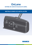
Maintenance Manual MM-1291
OnLane™ Lane Departure Warning (LDW)
System
Revised 05-14
Service Notes
About This Manual
This manual provides installation procedures as well as the
diagnostic procedures required to troubleshoot the OnLane™ lane
departure warning (LDW) system installed in a vehicle.
Before You Begin
1.
Read and understand all instructions and procedures before
you begin to service components.
2.
Read and observe all Warning and Caution hazard alert
messages in this publication. They provide information that can
help prevent serious personal injury, damage to components,
or both.
3.
Follow your company’s maintenance and service, installation,
and diagnostics guidelines.
4.
Use special tools when required to help avoid serious personal
injury and damage to components.
Hazard Alert Messages and Torque
Symbols
WARNING
A Warning alerts you to an instruction or procedure that you
must follow exactly to avoid serious personal injury and
damage to components.
CAUTION
A Caution alerts you to an instruction or procedure that you
must follow exactly to avoid damage to components.
How to Obtain Additional Maintenance,
Service and Product Information
Visit Literature on Demand at meritor.com to access and order
additional information.
Contact the Meritor OnTrac™ Customer Call Center at
866-668-7221 (United States and Canada); 001-800-889-1834
(Mexico); or email [email protected].
How to Obtain Replacement
Components
To order replacement components for the OnLane™ LDW System,
call Meritor’s Commercial Vehicle Aftermarket at 888-725-9355.
Please have the following information available:
앫 Truck make
앫 Truck model
앫 Truck model year
앫 LDW part number and serial number from the flag label located
on the LDW wiring pigtail
앫 Number of LDW system speakers
If Tools and Supplies are Specified in
This Manual
Contact Meritor’s Commercial Vehicle Aftermarket at
888-725-9355.
@
This symbol alerts you to tighten fasteners to a specified torque
value.
Information contained in this publication was in effect at the time the publication
was approved for printing and is subject to change without notice or liability.
Meritor WABCO reserves the right to revise the information presented or to
discontinue the production of parts described at any time.
Meritor WABCO Maintenance Manual MM-1291 (Revised 05-14)
Contents
pg. 1
2
3
Section 1: Introduction
Description
System Components
LDW Camera Module with Mounting Screws
LDW Windshield Mounting Bracket
LDW Mounting Bracket
Section 2: Diagnostics, Troubleshooting and
Testing
14
15
Inspection and Tests
Visual Inspection
Power On Self Test
Functional Check
LDW System Test
TOOLBOX™ 11.1 Software
OnLane™ LDW Diagnostic Trouble Code Table
Retrieving Video Capture Files
Circuit Descriptions and Diagnostics
Green LDW Enabled Indicator
Amber LDW Not Available Indicator
LDW Switch Input
Left Turn Signal Input
Right Turn Signal Input
Left Audio Warning Output
Right Audio Warning Output
Brake Switch Input
16
Section 3: Component Replacement
4
5
7
9
10
11
12
17
18
20
22
23
Procedures
New Installation of the LDW System
Replacing a New LDW Module on an Existing Bracket
Replacing a Complete LDW Module and Bracket
Wiring Harness Installation OnLane™
Connecting Wiring Harness to Vehicle Wiring
Verifying Correct System Operation
OnLane™ Circuit Mode Test
OnLane™ Test Mode Faults
1 Introduction
Description
1 Introduction
WARNING
The OnLane™ Lane Departure Warning (LDW) System employs a
camera mounted near the upper center of the windshield that
observes the vehicle’s position in its lane. In the event of a
unintentional lane change, the system alerts the operator of the
possible unintended event by sounding audible warnings through a
set of speakers. Figure 1.1.
Figure 1.1
The OnLane™ system was designed, manufactured and
installed as an operator assistant. This system is not intended
to replace good attentive driving behaviors and practices
which may change based upon traffic and road conditions.
Please refer to the OnLane™ Lane Departure Warning (LDW)
Drivers Guide for information on the correct operation and
understanding of the situations in which the system may not
provide assistance.
System Components
LDW Camera Module with Mounting Screws
This component has the following features. Figure 1.2.
앫 Dimensions (not including bracket) 5.39 x 2.2 x 1.39”
(136 x 56 x 34 mm) (W x H x D)
4010095a
Figure 1.1
The system operates automatically when the vehicle is moving on a
roadway with painted lane markings. It identifies intentional lane
changes by monitoring the turn signals, brake switch and vehicle
speed. The optional alertness and warning feature also assists the
operator by providing an audible warning when a predetermined
amount of lane drift or speed fluctuation has been exceeded.
앫 Weight: 0.86 lb (390 g) (including wiring pigtail)
앫 Cast aluminum with matte black finish
앫 Light shield feature protects lens, reduces reflections and
prevents tampering
앫 Attaches to bracket using two T-15 torx head screws.
Figure 1.2
System performance may be degraded or completely disabled under
these conditions.
앫 Dirty or damaged windshield
앫 Poor lighting conditions caused by inoperable headlamp(s) or
severe road glare
앫 Poor weather conditions such as snow, ice, heavy fog or heavy
rain
앫 Poor pavement conditions such as broken road surface, ice,
snow, sand, dirt or gravel covering the road surface
앫 Missing, worn, faded, damaged or covered lane markers
When the system cannot provide assistance, the vehicle’s amber
LDW Not Available indicator is turned ON. Resolution of these
factors should enable the system to automatically return to normal
operation, as indicated by the amber LDW Not Available indicator
being turned OFF.
4010097a
Figure 1.2
Meritor WABCO Maintenance Manual MM-1291 (Revised 05-14)
1
1 Introduction
LDW Windshield Mounting Bracket
This component has the following features. Figure 1.3.
앫 Dimensions: 3.15 x 1.69 x 0.28” (80 x 43 x 7 mm) (W x H x D)
앫 Weight: 0.66 lb (30 g)
앫 Cast aluminum with matte black finish
앫 Attaches to windshield using pressure-sensitive adhesive
앫 Optional low-profile bracket design allows application of bracket
at windshield supplier.
Figure 1.3
4010098a
Figure 1.3
LDW Mounting Bracket
A copy of the OnLane™ LDW Driver’s Guide can be downloaded at
Meritor.com. Figure 1.4.
Figure 1.4
System Startup
Lane Departure
Warning System
The system powers up when vehicle ignition is turned
on. The system performs a series of self tests during
startup. During the self test, the vehicle indicators
and vehicle speakers will operate briefly. After
successful completion, the vehicle’s GREEN enabled
indicator will be ON showing the system is ready for
use. Lane Departure Warning alerts become active
after vehicle reaches 42 MPH.
Vehicle Light Indicator Table
This Driver Tips Guide applies to trucks and tractors
equipped with the OnLane™ Lane Departure Warning
System with SafeTraK technology by Takata. OnLane
is a Camera-based warning system that observes
and calculates the truck’s position within the lane. In
the event of an unintentional lane change, the system
provides audible warnings to inform the driver of this
unintended event, alerting the driver to make
appropriate steering adjustments.
The system utilizes a camera mounted near the top
center of the vehicle windshield. Vehicle speakers
provide audible warnings. Included with the system
is the DAW (Driver Alertness Warning). This system
assists the driver by providing an audible warning
when the calculated alertness, based on the
vehicle’s stability within the lane, falls below an
alertness threshold.
Warning: The OnLane system was designed,
manufactured and installed as a driver assistant.
This system is not intended to replace good
attentive driving behaviors, which may change
based on traffic and road conditions. Please read
the following information to properly operate the
system and understand the situations in which
this system may not provide assistance.
Ready to Assist
GREEN ON / AMBER OFF
Not Ready to Assist
GREEN ON / AMBER ON
Driver has Disabled
(System Off / Power Off)
Fault Condition
GREEN OFF / AMBER OFF
GREEN OFF / AMBER ON
(refer to Flashing Code Operation)
Intentional Lane Changes
When a lane change is intentional the assistance
warnings are disabled. The system identifies
intentional lane changes by reacting to turn signal
use, brake switch and vehicle speed.
Brake = ON
All warnings are disabled
Left Turn = ON
Left departure warnings
are disabled
Right Turn = ON
Right departure warnings
are disabled
Speed Less than Minimum
All warnings are disabled
Hazard Warning Lights = ON Warnings are enabled
Note: Based on the installation method for your
vehicle, some of these signals may not be connected
and, therefore, not used in disabling warnings.
Lane Departure Warning
(Unintentional)
The system is constantly observing and calculating
the truck’s position within the lane. In the event of
an unintentional lane change, the system provides
audible warnings (rumble strip noise) to inform the
driver of this possible unintended event. This
warning is intended to alert the driver to make
appropriate steering adjustments.
Driver Alertness Warning (DAW)
The system detects erratic or degraded driving
based on weaving behavior within the driving lane.
Weaving within the lane is associated with driver
drowsiness and distraction. The DAW system
computes the drivers “Alertness Index” based upon
the degree of degraded driving. A unique warning
signal (audible beep) will be issued by the DAW
system if the drivers “Alertness Index” falls below
a predetermined threshold. After the DAW system
issues a warning, the driver should NOT continue to
operate the vehicle until the distraction is eliminated.
Temporarily Disabling the
System
Warnings are enabled when the vehicle’s GREEN
enable indicator is ON. The system warnings may
be temporarily disabled by pressing the enable
switch. This will disable warnings for approximately
10 minutes. While warnings are disabled, the
vehicle’s GREEN enable indicator will be OFF.
To enable warnings again, simply press the
enable switch.
4010792a
Figure 1.4
2
Meritor WABCO Maintenance Manual MM-1291 (Revised 05-14)
2 Diagnostics, Troubleshooting and Testing
Inspection and Tests
Power On Self Test
2 Diagnostics, Troubleshooting and Testing
Visual Inspection
Perform a visual inspection of the LDW system before proceeding
with any diagnosis.
앫 Ensure that the area of the windshield in front of the LDW is
clean and there is nothing obstructing the camera lens.
Figure 2.1.
The system performs a series of self tests on startup during which
the vehicle indicators and system speakers operate for
approximately one second. After successful completion of the
self-test, the vehicle’s green System Enabled indicator is ON,
indicating that the system is ready for use. If the Power ON Self
Tests do not complete successfully, the vehicle’s green System
Enabled indicator begins flashing to indicate which fault codes are
present. Refer to the fault code chart for further description of the
flash fault codes.
Figure 2.1
Functional Check
If the Power On Self tests are not successful, the vehicle’s green
System Enabled indicator begins to flash indicating the identified
fault(s).
The fault code is read by counting the series of green System
Enabled indicator flashes. For example, if a code 2, 3 is present, the
indicator will flash ON two times and then pause for 3 seconds and
flash ON 3 more times.
CLEAN
4010096a
Figure 2.1
앫 Ensure that the mounting bracket is firmly attached to the
windshield and that the LDW unit is firmly attached to the
mounting bracket by carefully trying to wiggle the LDW unit by
hand.
앫 Inspect for any visual damage to the mounting bracket of the
LDW unit.
앫 Ensure that there are no loose or corroded connections,
particularly where the LDW wiring may have been spliced into
the vehicle harness.
앫 Inspect the wiring for cut or frayed areas that could cause an
open circuit or a short to the vehicle body, which results in a
short-to-ground condition.
When the system has completed flashing out a fault code, it will turn
off the green System Enabled indicator for 6 seconds. If more than
one fault code is present, the system will flash out a new fault code
after the 6 second indicator off period. The system continues to
flash out new codes after each 6 second indicator off period is
completed until all codes have been flashed out.
To repeat the fault code flash sequence, push and release the LDW
Enable Switch.
LDW System Test
The LDW System test is intended to be used after the system is
installed in a vehicle to help verify the system is wired properly. It is
recommended that this procedure be performed whenever the
system has been newly installed in a vehicle or when repairs have
been made to the system wiring.
To enter the System test.
1.
Turn ignition key to power up cab. During start up, the green
and yellow indicators in the OnLane™ rocker switch are turned
on.
2.
Wait for the audible start-up tones to complete. If the indicators
do not light or there are no start-up tones, check the
OnLane™ power and ground connections, the switch
connections and the speaker connections.
Meritor WABCO Maintenance Manual MM-1291 (Revised 05-14)
3
2 Diagnostics, Troubleshooting and Testing
3.
Enter test mode by depressing the OnLane™ rocker switch at
least seven times within ten seconds after the audible start-up
tones are complete. The system indicates that it is in test mode
by giving a short tone through the left speaker followed by one
through the right speaker. In a single speaker system, both
tones will come through that speaker. While in test mode, the
green LDW Enabled indicator is turned off and the amber LDW
Not Available indicator flashes.
From the message box that appears, click on the OnLane™ LDW
Diagnostics button. Figure 2.3.
Figure 2.3
This test mode times out in 10 minutes. Turning off the vehicle
also causes the test mode to close.
If the amber LDW Not Available indicator is ON and green LDW
Enabled indicator is OFF, a system fault is present. The system
identifies the fault by flashing the green LDW Enabled indicator.
4010739a
If the left turn signal is activated while in test mode, the system
gives an audible tone through the left speaker.
If the right turn signal is activated while in test mode, systems
equipped with two speakers give an audible tone through the
right speaker.
Systems equipped with a single speaker give an audible tone
through the single speaker for both left and right turn signal
activation.
Figure 2.3
Retrieving Diagnostic Trouble Codes
1.
Once the OnLane™ Diagnostics button is selected, the active
Diagnostic Trouble Codes (DTCs) will be displayed. Figure 2.4.
Figure 2.4
If the brake pedal is pressed, the system will activate the green
LDW Enabled indicator.
If the green LDW Enabled indicator flashes, the system is
identifying a fault listed in Table A.
TOOLBOX™ 11.1 Software
NOTE: You must use TOOLBOX™ 11.1 Software or higher. To
download TOOLBOX™ 11.1 Software, visit meritorwabco.com.
To access the Meritor WABCO TOOLBOX™ 11.1 Software from the
desktop screen, double-click on the Meritor WABCO TOOLBOX™
icon. Figure 2.2.
Figure 2.2
4010594a
Figure 2.2
4
Meritor WABCO Maintenance Manual MM-1291 (Revised 05-14)
4010740a
Figure 2.4
2.
A description of the DTC, the number of times the DTC
occurred, the suspect parameter number (SPN) and the failure
mode identifier (FMI) are all displayed in the Diagnostic Trouble
Codes window. After making the necessary repairs, OnLane™
LDW will clear the DTCs.
2 Diagnostics, Troubleshooting and Testing
OnLane™ LDW Diagnostic Trouble Code
Table
The following table provides repair instructions and the
corresponding Troubleshooting Sections in this manual for SPN/FMI
DTCs that are readable using TOOLBOX™ 11.1 Software. If the
display shows a code not listed in the table, contact the Meritor
OnTrac™ Customer Call Center at 866-OnTrac1 (668-7221) for
assistance.
Table A: OnLane™ LDW Diagnostic Trouble Codes
SPN
Blink Code (dec)
FMI (dec) Description
Detection Method
Action
1
1705
7
Dirty windshield
If the system detects a dirty or blocked window
Clean
windshield,
remove visual
obstructions
2
1705
31
LDW Malfunction
Any non-recoverable, internal LDW failure. This fault can be set Call OnTrac™ at
by any of the following: - DSP memory access and memory write 866-668-7221.
failures on power up. - Imager communication fault received from
the DSP. - Detection of VIOP VBATT voltage < 9 or > 32. - DSP
1.8 voltage supply > 1.91 or < 1.7- DSP 1.2 voltage supply >
1.28 or < 1.12 - VIOP to DSP initialization problems after 10
retries. - Imager over temperature
3
1705
15
ECU Over
Temperature
If temperature at image sensor is > 85°C
Provide cooling
to the OnLane™
unit and retest
after the unit is
cooled to touch.
3, 1
3564
4
LDW Switch input
stuck Low
If (LDW Enable/Disable Source = discrete) and (LDW Enable/
Disable Switch Type = momentary) and LDW switch input is
stuck low for 1 +/-10% minute
Service LDW
switch circuit
3, 2
2368
2
Left turn signal input If (Turn Signal Source = J1939) AND the J1939 OEL message Service Left turn
stuck high
indicates left turn signal error or not available, OR if OEL message signal circuit
is not received.
If (Turn Signal Source = VP37) AND the VP37 message indicates
left turn signal error or not available, OR if VP37 message is not
received.
3, 3
2370
2
Right turn signal
input stuck high
If (Turn Signal Source = J1939) AND the J1939 OEL message
indicates right turn signal error or not available, OR if OEL
message is not received.
Service Right
turn signal
circuit
If (Turn Signal Source = VP37) AND the VP37 message indicates
right turn signal error or not available, OR if VP37 message is not
received.
Meritor WABCO Maintenance Manual MM-1291 (Revised 05-14)
5
2 Diagnostics, Troubleshooting and Testing
SPN
Blink Code (dec)
FMI (dec) Description
Detection Method
3, 4
597
2
Brake input stuck
high
If (Brake Source = J1939)AND brake status equals error value as Service Brake
defined in J1939. This is checked whenever the J1939 message input circuit
is received.
4, 1
1702
3
Enabled indicator
short to battery
Low-side driver chip diagnostics. Tested on power on and when Service Enabled
LDW enable indicator transition from off to on.
indicator short to
battery
4, 3
1702
5
Low-side driver chip diagnostics. Tested on power on and when Service Enabled
Enabled indicator
indicator circuit
output open or short LDW enable indicator transition from on to off
open or short to
to ground
ground
5, 1
1710
3
Not Available
Low-side driver chip diagnostics. Tested on power on and when Service Not
indicator output short Not Available indicator transition from on to off
Available
to battery
indicator circuit
short to battery
5, 3
1710
5
Low-side driver chip diagnostics. Tested on power on and when Service Not
Not Available
Available
indicator output open Not Available indicator transition from on to off
indicator circuit
or short to ground
open or short to
ground
6, 1
1704
31
Left audio warning
ouput problem
6, 2
1703
31
Right audio warning Any detectable problem with the DAC or audio amplifier. Reported Service right
output problem
if SPI communications to the DAC fails.
audio speaker
and/or circuit
7, 1
639
31
J1939 network
problem
If vehicle speed message is not received
8, 1
628
2
OnLane™ ECU
internal failure
If memory check fails. EEPROM crc does not match the crc that is Call OnTrac™ at
stored for the used EEPROM range, set this fault. Tested
866-668-7221.
periodically
8, 2
630
2
OnLane™ ECU
internal failure
If calibration file is missing or corrupt. Reported whenever DSP
reports a corruption.
6
Action
Any detectable problem with the DAC or audio amplifier. Reported Service left
if SPI communications to the DAC fails.
audio speaker
and/or circuit
Meritor WABCO Maintenance Manual MM-1291 (Revised 05-14)
Verify J1939
data is on the
vehicle
communications
bus using the
standard vehicle
diagnostic tool.
If normal vehicle
communications
exist, service the
vehicle wiring to
the LDW
connector.
Call OnTrac™ at
866-668-7221.
2 Diagnostics, Troubleshooting and Testing
Retrieving Video Capture Files
1.
Figure 2.6
If the OnLane™ module has video and data capture enabled,
the download can be retrieved by clicking on the Video menu.
This will open a new window. Figure 2.5.
Figure 2.5
4011168a
Figure 2.6
4011167a
Figure 2.5
2.
From the VDR tab in the new window, select the ‘Read VDR
Log’. This will load the logs from the module into the file list.
3.
Select a file from the file list to download or preview.
4.
Clicking the ‘View Preview’ button will display the image at the
moment the event occurred.
5.
Clicking the ‘Read Selected Clips’ button will initiate the video
download.
The video file will be downloaded in .mov file format. The video
will show the recording along with the frame numbers. When
the frame number turns red, this indicates when the event
recording was triggered.
6.
Clicking the ‘Read Data From Selected’ button will initiate the
data download. Figure 2.6.
The data file will be downloaded in a .csv file format. The data
will show the reason why the event was recorded along with
several other pieces of vehicle data. Refer toTable B and Table
C to analyze this data.
Meritor WABCO Maintenance Manual MM-1291 (Revised 05-14)
7
2 Diagnostics, Troubleshooting and Testing
Table B: Trigger Definition
Trigger Number Trigger Mask Trigger Name
Details
2
0x0004
Hard Brake
Vehicle speed decreases by 7 mph in 1 second
16
0x10000
ABS
If ABS is active (PGN 61441 SPN 563) for 1 second and speed > 20 mph
17
0x20000
ATC
If brake control (SPN 562) active for 1 second or engine control (SPN 561) active for
1 second
18
0x40000
RSC
If speed > 20 mph and [If brake control (SPN 1818) active at all or engine control
(SPN1816) active for 1 second]
19
0x80000
ESC
If speed > 20 mph and [If brake control (SPN 1819) active at all or engine control
(SPN1817) active for 1 second]
20
0x100000
External FCW Audible If ACC1 SPN 5022 from src 0x2A and XBR (pgn 1024 SPN 2920) is 0
21
0x200000
External FCW Haptic
If ACC1 SPN 5022 from src 0x2A and XBR (pgn 1024 SPN 2920) is -2.5 m/s^2
22
0x400000
External FCW CMB
If ACC1 SPN 5022 from src 0x2A and XBR (pgn 1024 SPN 2920) is -3.5 m/s^2
Table C: EDR Column Definitions
Column Name
Description
frame_num
Image frame number (Increments 30 times per second). This can be useful for matching EDR data to VDR
frames.
odometer (m)
Vehicle odometer
trigger_reason
The reason the VDR/EDR event was recorded.
trigger_mask
Trigger events that occurred during (but not necessarily have caused) the recording.
LDW_mute
0 = LDW system enabled, 1 = LDW system manually disabled by the driver
wipers
0 = wipers off or not connected to OnLane™, 1 = wipers on
left_turn
0 = left turn signal off, 1 = left turn signal on
right_turn
0 = right turn signal off, 1 = right turn signal on
brake
0 = brake off, 1 = brake on
speed (cm/s)
Speed of the OnLane™ equipped vehicle.
yaw_rate (rad/s)
Yaw rate of the OnLane™ equipped vehicle.
yaw_rate_valid
0 = OnLane™ is not receiving a valid yaw rate signal, 1 = yaw rate signal is being received
system_error
0 = no error present, 1 = OnLane™ is in a fault condition
FCW_mute
0 = the vision-based FCW is neither disabled by the driver nor by a radar-based FCW system. 1 = The
vision-based FCW is disabled by the driver or by a radar-based FCW system.
silence
0 = No vehicle system has disabled OnLane™, 1 = an external vehicle system is disabling OnLane™
AI_alertness_index
Driver Alertness Index. Range 0-100. Numbers greater than 60 indicate the driver seems to be alert.
LDAT_lateral_offset
Distance between vehicle center and center of the lane in cm (right is positive).
FCW_ttc (ms)
The visually estimated time to collision.
FCW_range (cm)
The visually estimated range to the target.
HWW_headway (ms)
The visually estimated time gap between the OnLane™ equipped vehicle and the lead vehicle.
8
Meritor WABCO Maintenance Manual MM-1291 (Revised 05-14)
2 Diagnostics, Troubleshooting and Testing
Circuit Descriptions and Diagnostics
2.
Green LDW Enabled Indicator
앫 If 12 +/- 3 volts are present: This condition should have
set a code 4, 1 during LDW key-on self test. There is a
short in the power between the LDW Enabled indicator
circuit between the LDW connector and the Enabled
connector. Repair this short.
Mounting locations for the LDW Enabled indicator vary with vehicle
application. Please consult the system user’s manual for the location
in your vehicle.
The following simplified diagram represents the green LDW
indicator circuit. Although they may not be shown here, additional
in-line connectors and splices may be present in the circuit
depending upon the particular vehicle installation. Figure 2.7.
앫 If there is no voltage: Go to Step 3.
3.
B7
IGNITION
SWITCH
앫 If there is no continuity: Go to Step 4.
FUSE
OnLane™
BATTERY
A7
Use an ohmmeter to check for continuity between terminal B7
and the ground terminal B9.
앫 If there is continuity: This condition should have set a
code 4, 3 during LDW key-on self test. Service the short to
ground in LDW Enabled indicator circuit.
Figure 2.7
LDW ENABLED
INDICATOR
(GREEN)
Remove the fuse powering the LDW Enabled indicator.
Measure the voltage between terminal B7 and the ground
terminal B9.
+
–
4.
NOT AVAILABLE
INDICATOR
(GREEN)
If there is no continuity: This condition should have set a
code 4, 3 during LDW key-on self test. Service open in the
LDW Enabled indicator circuit between the LDW connector and
the LDW indicator fuse.
If there is continuity: Service or replace LDW Enabled
indicator.
4010099a
Figure 2.7
Amber LDW Not Available Indicator
Circuit Diagnosis
1.
Disconnect the vehicle side of the LDW connector and measure
for voltage from B7 to the ground terminal B9. Figure 2.8.
Figure 2.8
A1
Mounting locations for the LDW Not Available indicator varies with
vehicle application. Please consult the system’s user manual for the
location in your vehicle.
The following simplified diagram represents the amber LDW Not
Available indicator circuit. Although they may not be shown here,
additional in-line connectors and splices may be present in the
circuit, depending upon the particular vehicle installation.
Figure 2.9.
Figure 2.9
LDW ENABLED
INDICATOR
(GREEN)
B9
B7
B1
4010100a
Figure 2.8
B7
IGNITION
SWITCH
FUSE
OnLane™
BATTERY
A7
앫 If 12 +/- 3 volts are present: Continue to Step 2.
앫 If there is no voltage on B7: Go to Step 3.
+
–
NOT AVAILABLE
INDICATOR
(GREEN)
4010099a
Figure 2.9
Meritor WABCO Maintenance Manual MM-1291 (Revised 05-14)
9
2 Diagnostics, Troubleshooting and Testing
앫 If there is no continuity: This condition should have set a
code 5, 3 during LDW key-on self test. Service open in the
LDW Enabled indicator circuit between the LDW connector
and the LDW indicator fuse.
Circuit Diagnosis
1.
Disconnect the vehicle side of the LDW connector and measure
for voltage from terminal A7 to the ground terminal B9.
Figure 2.10.
앫 If there is continuity: Service or replace LDW Not Available
indicator.
Figure 2.10
A7
A1
LDW Switch Input
Mounting locations for the LDW switch vary with vehicle application.
Please consult the system’s user manual for the location in your
vehicle.
B9
B1
4010102a
The following simplified diagram represents the LDW switch
indicator circuit. Although they may not be shown here, additional
in-line connectors and splices may be present in the circuit,
depending upon the particular vehicle installation. Figure 2.11.
Figure 2.10
Figure 2.11
앫 If the measured voltage is in the range of 12 +/- 3
volts: Continue to Step 2.
앫 If there is no voltage on A7: Go to Step 3.
2.
LDW ENABLE/
DISABLE
SWITCH
Remove the fuse powering the LDW Not Available indicator.
Measure the voltage between terminal A7 and the ground
terminal B9.
앫 If the measured voltage is in the range of 12 +/- 3
volts: This condition should have set a code 5, 1 during
LDW key-on self test. There is a short in the power in the
LDW Not Available indicator circuit between the LDW Not
Available connector and the LDW connector. Repair this
short.
Use an ohmmeter to check for continuity between terminal A7
and the ground terminal B9.
OnLane™
4010115a
Figure 2.11
Circuit Diagnosis
1.
앫 If there is no voltage present: Go to Step 3.
3.
B8
Disconnect the vehicle side of the LDW connector and measure
for voltage from terminal B8 to the ground terminal B9.
Figure 2.12.
Figure 2.12
앫 If there is continuity: This condition should have set a
code 5, 3 during LDW key-on self test. Service the short to
ground in LDW Not Available indicator circuit.
A1
앫 If there is no continuity: Go to Step 4.
4.
Remove the fuse from the output side of the LDW indicator
fuse holder. Measure continuity between this fuse holder and
terminal A7.
B9 B8
Figure 2.12
10
Meritor WABCO Maintenance Manual MM-1291 (Revised 05-14)
B1
4010116a
2 Diagnostics, Troubleshooting and Testing
2.
앫 If there is no voltage on B8: Continue to Step 2.
Circuit Diagnosis
앫 If voltage is present: Repair short to power on LDW
enable switch circuit.
1.
Disconnect the LDW connector and hold the LDW enable/
disable switch closed. Measure for continuity between terminal
B8 and the ground terminal B9.
Turn on the left turn signal and measure the voltage from
terminal A4 to the ground terminal B9. Figure 2.14.
앫 If there is continuity: Continue to Step 3.
앫 If there is no continuity to the ground terminal B9:
Service open in the in switch circuit between LDW
connector and switch.
3.
Verify correct vehicle turn signal operation to make sure turn
signal switch and relay(s) are functioning properly. Proceed
with the following steps only if vehicle turn signals operate
properly.
Figure 2.14
A4
A1
While NOT holding the LDW enable/disable switch closed,
measure for continuity between terminal B8 and the ground
terminal B9.
앫 If there is continuity: This condition should have set a
code 3, 1 during LDW key-on self test. Service the short to
ground in LDW switch input circuit.
앫 If there is no continuity between terminal B8 and the
ground terminal B9: Perform LDW System test.
B9
B1
4010114a
Figure 2.14
Left Turn Signal Input
The voltage should be switching between 12 +/-3 and 0 volts.
The following simplified diagram represents the left turn signal input
circuit. The LDW receives left turn signal information directly from
the vehicle’s turn signal circuit without any relays or additional
switches. Verify that the vehicle turn signals are operating properly
before beginning any testing of the LDW turn signal inputs.
앫 If there is no voltage on A4: Continue to Step 2.
앫 If voltage is present, but does not switch: This condition
should have set a code 3, 2 during LDW key-on self test.
Service short to power on turn signal circuit.
앫 If voltage switches between 12 +/- 3 and 0 volts and
code 3, 2 was set during LDW key-on self test: Rerun
the key-on self test and contact Customer Support if code
still occurs.
Although they are not shown here, additional in-line connectors and
splices may be present in the circuit, depending upon the particular
vehicle installation. Figure 2.13.
2.
Figure 2.13
LEFT TURN
FLASHER CONTACT
A4
LEFT
RIGHT TURN TURN LAMP
FLASHER
CONTACT
B4
+
BATTERY –
RIGHT
TURN LAMP
OnLane™
Turn off the turn signal and disconnect the LDW connector.
Measure for continuity between terminal A4 and the ground
terminal B9.
앫 If there is continuity between terminal A4 and the
ground terminal B9: Service short to the ground terminal
B9 in the left turn signal input circuit.
앫 If there is no continuity to ground: Service open in the
left turn signal circuit to LDW.
4010113a
Figure 2.13
Meritor WABCO Maintenance Manual MM-1291 (Revised 05-14)
11
2 Diagnostics, Troubleshooting and Testing
Right Turn Signal Input
The voltage should be switching between 12 +/-3 and 0 volts.
The following simplified diagram represents the right turn signal
input circuit. The LDW receives right turn signal information directly
from the vehicle’s turn signal circuit without any relays or additional
switches. Verify that the vehicle turn signals are operating properly
before beginning any testing of the LDW turn signal inputs.
앫 If there is no voltage on B4: Continue to Step 2.
앫 If voltage is present, but does not switch: This condition
should have set a code 3, 3 during LDW key-on self test.
Service short to power on turn signal circuit.
앫 If voltage switches between 12 +/- 3 and 0 volts and
code 3, 3 was set during LDW key-on self test: Rerun
the key-on self test and contact Customer Support if code
still occurs.
Although they are not shown here, additional in-line connectors and
splices may be present in the circuit, depending upon the particular
vehicle installation. Figure 2.15.
2.
Figure 2.15
LEFT TURN
FLASHER CONTACT
A4
LEFT
RIGHT TURN TURN LAMP
FLASHER
CONTACT
B4
+
BATTERY –
RIGHT
TURN LAMP
앫 If there is continuity between terminal B4 and the
ground terminal B9: Service short to the ground terminal
B9 in the right turn signal input circuit.
OnLane™
앫 If there is no continuity to ground: Service open in the
right turn signal circuit to LDW.
4010113a
Figure 2.15
Circuit Diagnosis
1.
Turn off the turn signal and disconnect the LDW connector.
Measure for continuity between terminal B4 and the ground
terminal B9.
Verify correct vehicle turn signal operation to make sure turn
signal switch and relay(s) are functioning properly. Proceed
with the following steps only if vehicle turn signals operate
correctly.
Left Audio Warning Output
The following simplified diagram represents the left speaker circuit.
Although they are not shown here, additional in-line connectors and
splices may be present in the circuit, depending upon the particular
vehicle installation. The LDW speaker outputs are compatible with
both 4 ohm and 8 ohm speakers. Figure 2.17.
Figure 2.17
Turn on the right turn signal and measure the voltage from
terminal B4 to the ground terminal B9. Figure 2.16.
A1
LEFT
SPEAKER
+
–
OnLane™
Figure 2.16
B1
A2
+
–
A1
B2
RIGHT
SPEAKER
(IF EQUIPPED)
4010107a
Figure 2.17
B9
B4
B1
4010112a
Figure 2.16
12
Meritor WABCO Maintenance Manual MM-1291 (Revised 05-14)
2 Diagnostics, Troubleshooting and Testing
앫 If there is continuity between the B1 terminal and
ground: Service the short to ground in the left speaker out
negative circuit.
Circuit Diagnosis
1.
Disconnect the LDW connector and measure from terminal A1
to the ground terminal B9 on the vehicle harness side for short
to 12 volts. Figure 2.18.
앫 If there is no continuity to ground: Continue to Step 6.
6.
Figure 2.18
A1
Disconnect the left front speaker and measure resistance
between terminal A1 and left speaker positive terminal at the
speaker connector.
앫 If resistance is less than one ohm between terminal A1
at the LDW connector and the left speaker positive
terminal: Continue to Step 7.
앫 If resistance is greater than one ohm between terminal
A1 at the LDW connector and the left speaker positive
terminal: Service open in left speaker positive wiring.
B9
4010108a
7.
Figure 2.18
앫 If the measured voltage is in the range of 12 +/- 3
volts: Repair short to battery in left audio warning output.
앫 If resistance is less than one ohm between terminal B1
at the LDW connector and left speaker positive
terminal: Continue to Step 8.
앫 If there is no voltage: Continue to Step 2.
2.
앫 If there is no voltage: Continue to Step 3.
3.
앫 If resistance is greater than 1 ohm: Service open in left
speaker negative wiring.
Measure from terminal B1 to the ground terminal B9 for a short
to 12 volts on the vehicle harness side.
앫 If the measured voltage is in the range of 12 +/- 3
volts: Repair short to battery in left audio warning output.
Disconnect the left front speaker and measure resistance
between terminal B1 and left speaker negative terminal at the
speaker connector.
8.
Connect a known good speaker to the left speaker connector
and rerun the system diagnostic test.
앫 If the system diagnostic tests pass the left speaker
testing: Replace the original speaker with a new one.
Measure from terminal A1 to terminal B1 on the vehicle
harness side for left speaker resistance.
앫 If resistance is less than 3 ohms: Service the short
between speaker wires.
앫 If resistance is approximately 4 ohms or approximately
8 ohms: Continue to Step 4.
앫 If resistance is greater than 9 ohms: Continue to Step 6.
4.
Measure the resistance between terminal A1 and ground.
앫 If there is continuity between the A1 terminal and
ground: Service the short to ground in the left speaker out
positive circuit.
앫 If there is no continuity to ground: Continue to Step 5.
5.
Measure the resistance between terminal B1 and ground.
Meritor WABCO Maintenance Manual MM-1291 (Revised 05-14)
13
2 Diagnostics, Troubleshooting and Testing
Right Audio Warning Output
Figure 2.21
The following simplified diagram represents the right speaker
circuit. Although they are not shown here, additional in-line
connectors and splices may be present in the circuit, depending
upon the particular vehicle installation. The LDW speaker outputs
are compatible with both 4 ohm and 8 ohm speakers. Figure 2.19.
Figure 2.19
A1
LEFT
SPEAKER
B9
4010105a
+
–
OnLane™
Figure 2.21
B1
A2
앫 If the measured voltage is in the range of 12 +/- 3
volts: Repair short to battery in the right audio warning
output.
+
–
B2
RIGHT
SPEAKER
(IF EQUIPPED)
앫 If there is no voltage: Continue to Step 3.
4010103a
3.
Figure 2.19
Circuit Diagnosis
1.
B2
Measure from terminal A2 to terminal B2 on the vehicle
harness side for right speaker resistance. Figure 2.22.
Figure 2.22
Disconnect the LDW connector and measure from terminal A2
to the ground terminal B9 on the vehicle harness side for short
to 12 volts. Figure 2.20.
A2 A1
Figure 2.20
A2
B2 B1
4010106a
Figure 2.22
앫 If resistance is less than 3 ohms: Service the short
between speaker wires.
B9
4010104a
앫 If resistance is approximately 4 ohms or approximately
8 ohms: Continue to Step 4.
Figure 2.20
앫 If the measured voltage is in the range of 12 +/- 3
volts: Repair short to battery in right audio warning output.
앫 If there is no voltage: Continue to Step 2.
2.
Measure from terminal B2 to the ground terminal B9 on the
vehicle harness side for short to 12 volts. Figure 2.21.
앫 If resistance is greater than 9 ohms: Continue to Step 6.
4.
Measure resistance between terminal A2 and ground.
앫 If there is continuity between the A2 terminal and
ground: Service the short to ground in the right speaker out
positive circuit.
앫 If there is no continuity to ground: Continue to Step 5.
14
Meritor WABCO Maintenance Manual MM-1291 (Revised 05-14)
2 Diagnostics, Troubleshooting and Testing
5.
Measure resistance between terminal B2 and ground.
Figure 2.23
앫 If there is continuity between the B2 terminal and
ground: Service the short to ground in the left speaker out
negative circuit.
BRAKE
SWITCH
앫 If there is no continuity to ground: Continue to Step 6.
6.
Disconnect the right speaker and measure resistance between
terminal A2 and the right speaker positive terminal at the
speaker connector.
앫 If resistance is less than one ohm between terminal A2
and the right speaker positive terminal: Continue to
Step 7.
앫 If resistance is greater than one ohm between terminal
A2 and the right speaker positive terminal: Service open
in right speaker positive wiring.
7.
OnLane™
BRAKE
LAMP
4010117a
Figure 2.23
Circuit Diagnosis
1.
Disconnect the right front speaker and measure resistance
between terminal B2 and the right speaker negative terminal at
the speaker connector.
Verify correct vehicle brake light operation to make sure brake
switch is not out of adjustment or stuck closed. Proceed with
the following steps only if vehicle brake lights operate correctly.
Disconnect the LDW connector and measure for voltage
between terminal A8 and the ground terminal B9 on the vehicle
harness side of the connector. Do not press the brake pedal at
this time.
앫 If resistance is less than one ohm between terminal B2
and the right speaker negative terminal: Continue to
Step 8.
8.
A8
+
BATTERY –
앫 If resistance is greater than one ohm between terminal
B2 and the right speaker negative terminal: Service
open in right speaker positive wiring.
앫 If the measured voltage on A8 is in the range of
12 +/- 3 volts: This condition should set a LDW self test
fault code of 3, 4. Service short to power in circuit between
LDW connector and vehicle harness.
Connect a known good speaker to the right speaker connector
and rerun the system diagnostic test.
앫 If there is no voltage: Continue to Step 2.
앫 If the system diagnostic tests pass the right speaker
testing, replace the original speaker with a new one.
Brake Switch Input
The following simplified diagram represents the brake switch signal
input circuit. The LDW receives brake signal information directly
from the vehicle’s brake light circuit without any additional relays or
switches. Verify that the vehicle brake signals are operating
correctly before beginning any testing of the LDW brake signal input.
Although they may not be shown here, in-line connectors and
splices may be present in the circuit depending upon the particular
vehicle installation.
2.
Press and hold the brake pedal while back probing the LDW
connector and measure for voltage between terminal A8 and
the ground terminal B9. There should be 12 +/-3 volts on
terminal A8 only when the brake switch is held down.
앫 If there is no voltage: Service open in circuit between
LDW connector and brake light switch.
앫 If the voltage is present only when the brake switch is
held down and LDW self test code 3, 4 is present:
Replace the LDW unit.
In some vehicles, the brake signal is received by the J1939 bus
instead of by a discrete input on Terminal A8. Figure 2.23.
Meritor WABCO Maintenance Manual MM-1291 (Revised 05-14)
15
3 Component Replacement
Hazard Alert Messages
3 Component Replacement
Hazard Alert Messages
Read and observe all Warning and Caution hazard alert messages in
this publication. They provide information that can help prevent
serious personal injury, damage to components, or both.
WARNING
To prevent serious eye injury, always wear safety eye
protection when you perform vehicle maintenance or service.
WARNING
Before securing the bracket to the windshield, note that the
locations of the mounting screws on the bracket are not tapped. We
recommend that you install the bracket to the LDW module before
installing it in the vehicle. Use the self-tapping mounting screws of
the LDW module to start the threads for the mounting screws on the
bracket. This action will allow for easier installation of the LDW
module to the bracket, once the bracket is installed to the
windshield.
The LDW system should only be installed on a windshield when the
glass temperature is within the recommended range between 70–
100°F (21– 37°C). Do not apply the bracket if the windshield
temperature is below 60°F (15°C).
Park the vehicle on a level surface. Block the wheels to
prevent the vehicle from moving. Support the vehicle with
safety stands. Do not work under a vehicle supported only by
jacks. Jacks can slip and fall over. Serious personal injury and
damage to components can result.
1.
Loosen the headliner and A-pillar trim panels as outlined in the
vehicle service manual to allow room to route the wiring behind
the header panel and down the A-pillar.
2.
Clean the windshield mounting surface with IPA wipe (50/50
mix of isopropyl alcohol and water) or equivalent cleaner.
Procedures
3.
New Installation of the LDW System
Allow the mounting surface to dry completely before
proceeding to the next step. The windshield surface must be
free of all oil, moisture and dirt for correct mounting bracket
adhesion.
The procedure for installing a new LDW system will vary depending
on the vehicle in which the unit is being installed. Each vehicle may
have slightly different routing and wiring requirements.
NOTE: To download mounting bracket installation templates,
visit the OnLane™ literature web page at meritorwabco.com.
4.
Align the template so that the markings on the template are
square to the centerline markings and the frit/trim line
markings at the top of the windshield. Figure 3.1. The template
shown is an example only.
Figure 3.1
WINDSHIELD
CENTERLINE
MARKER
Black trim at top of windshield.
NOTE: This line may not be straight or level.
(EXAMPLE
TEMPLATE ONLY)
35 MM ± 5 MM
OnLane™ Bracket:
P/N 400 873 101 0
216 MM ± 5 MM
Install bracket so the bottom
surface of camera is level ±1.5"
when truck is parked on level surface.
Figure 3.1
16
Meritor WABCO Maintenance Manual MM-1291 (Revised 05-14)
4011169a
3 Component Replacement
5.
Remove the liners from the adhesive pads on the bracket.
Figure 3.2.
10. Connect the LDW connector to the vehicle wiring harness and
tuck the connector behind the headliner.
11. Perform the power-on self test and verify that there are no fault
codes present in the LDW module.
Figure 3.2
12. Perform the LDW system test.
13. Install the headliner as described in the vehicle service manual
procedures.
Replacing a New LDW Module on an Existing
Bracket
4010120a
Figure 3.2
6.
Hold the bottom of the bracket slightly away from the glass and
align the top of the bracket to the top of the template cutout.
7.
Bring the bottom of the bracket adhesive pads into contact with
the glass and press the bracket firmly against the glass.
Maintain a minimum of 45 pounds of force for 30 seconds.
Wait 15–30 minutes for the mounting bracket adhesive to set.
8.
Remove the yellow lens cap from the new LDW unit and
position the LDW unit onto the mounting bracket in a slightly
swung up position to align the upper tab. Align the two lower
tabs on the LDW unit by rotating the unit downward with the
lower tabs on the mounting bracket. Figure 3.3.
You can replace a damaged or faulty LDW unit on the existing
bracket provided that the mounting screw holes in the bracket are
not damaged or worn.
1.
Disconnect the vehicle battery.
2.
Loosen the forward portion of the headliner as outlined in the
vehicle service manual to gain access to the LDW connector.
3.
Disconnect the LDW connector from the vehicle wiring
harness.
4.
Back out the two T15 torx head screws far enough to
disengage the screws from the windshield mounting bracket.
5.
Rotate the LDW unit upward and back slightly to disengage
from the bracket. Figure 3.4.
Figure 3.4
Figure 3.3
4010122a
Figure 3.4
4010121a
6.
Figure 3.3
9.
Install the two T15 torx head screws holding the LDW to the
mounting bracket. Tighten the screws to 2.5 +/- 0.4 N폷m (22
+/- 3.5 ft-lb). DO NOT OVERTIGHTEN.
Remove the yellow lens cap from the new LDW unit. Position
the new LDW unit onto the mounting bracket in a slightly
swung up position to align the upper tab and rotate the unit
downward to align the two lower tabs on the LDW unit with the
lower tabs on the mounting bracket.
Follow the instructions on the template. Figure 3.5.
Meritor WABCO Maintenance Manual MM-1291 (Revised 05-14)
17
3 Component Replacement
Before securing the bracket to the windshield, note that the
locations of the mounting screws on the bracket are not tapped. We
recommend that you install the bracket to the LDW module before
installing it in the vehicle. Use the self-tapping mounting screws of
the LDW module to start the threads for the mounting screws on the
bracket. This action will allow for easier installation of the LDW
module to the bracket, once the bracket is installed to the
windshield.
Figure 3.5
4010121a
Figure 3.5
7.
8.
9.
Install the two T15 torx head screws holding the LDW to the
mounting bracket. Tighten the screws to 1.7 +/- 0.2 N폷m
(13.2 +/- 1.5 ft-lb). Re-installation of the mounting screws into
an existing bracket requires less torque than the original
installation of the screws. DO NOT OVERTIGHTEN.
Connect the LDW connector to the vehicle wiring harness and
tuck the connector back into its original position behind the
headliner.
The LDW system should only be installed on a windshield when the
glass temperature is within the recommended range between
70–100°F (21– 37°C). Do not apply the bracket if the windshield
temperature is below 60°F (15°C).
1.
If necessary, remove the LDW unit from the bracket, back out
the two T15 torx head screws far enough to disengage the
screws from the windshield mounting bracket.
2.
If necessary, rotate the LDW unit upward and back slightly to
disengage from the bracket, and secure the unit to the sun
visor. Do not let the unit hang by the wiring harness.
Figure 3.6.
Figure 3.6
Perform the power-on self test and verify that there are no fault
codes present in the LDW module.
10. Install the headliner per the vehicles service manual
procedures.
Replacing a Complete LDW Module and
Bracket
4010122a
Install a new LDW mounting bracket if any of the following
conditions occur.
Figure 3.6
앫 If a new system is being installed.
앫 If the windshield has been replaced and the new windshield does
not contain a LDW mounting bracket.
앫 If the mounting bracket has become loose or has fallen off the
windshield.
앫 If the mounting bracket screw holes have become stripped or
damaged.
앫 If the mounting bracket has been removed.
18
Meritor WABCO Maintenance Manual MM-1291 (Revised 05-14)
3.
If necessary, remove bracket using a putty knife, razor blade or
similar tool. Scrape bracket at edges and pry loose. Figure 3.7.
3 Component Replacement
Figure 3.7
4010125a
Figure 3.7
4.
If necessary, remove all adhesive and other contaminants from
the windshield. Failure to remove all material from glass may
result in inadequate adhesion of new bracket. Clean the
windshield mounting surface with IPA wipe (50/50 mix of
isopropyl alcohol and water) or equivalent cleaner.
5.
Allow the mounting surface to dry completely before
proceeding to the next step. The windshield surface must be
free of all oil, moisture and dirt for correct mounting bracket
adhesion.
NOTE: To download mounting bracket installation templates,
visit the OnLane™ literature web page at meritorwabco.com.
6.
Align the template so that the markings on the template are
square to the centerline markings and the frit/trim line
markings at the top of the windshield. Figure 3.8. The template
shown is an example only.
Figure 3.8
WINDSHIELD
CENTERLINE
MARKER
Black trim at top of windshield.
NOTE: This line may not be straight or level.
(EXAMPLE
TEMPLATE ONLY)
35 MM ± 5 MM
OnLane™ Bracket:
P/N 400 873 101 0
216 MM ± 5 MM
Install bracket so the bottom
surface of camera is level ±1.5"
when truck is parked on level surface.
4011169a
Figure 3.8
Meritor WABCO Maintenance Manual MM-1291 (Revised 05-14)
19
3 Component Replacement
7.
Remove the liners from the adhesive pads on the bracket.
Figure 3.9.
Figure 3.9
Wiring Harness Installation OnLane™
1.
Install the system wiring harness as shown. Make sure that you
do not pinch or cut the cables or wiring during installation of
the harness and trim panel or trim panel attaching screws.
Figure 3.11.
Use zip ties or straps as necessary to secure the harness to
prevent movement that may cause vibrations or compromise
harness integrity. Be careful to ensure that the wiring harness
is clear of all screw locations, including headliner and visor
locations. This prevents intrusions that may affect the integrity
of the wiring harness.
4010120a
Figure 3.9
8.
Hold the bottom of the bracket slightly away from the glass and
align the top of the bracket to the top of the template cutout.
9.
Bring the bottom of the bracket adhesive pads into contact with
the glass and press the bracket firmly against the glass.
Maintain a minimum of 45 pounds of force for 30 seconds.
Wait 15–30 minutes for the mounting bracket adhesive to set.
Figure 3.10.
Figure 3.10
4010121a
Figure 3.10
10. Remove the yellow lens cap from the new LDW unit and
position the LDW unit onto the mounting bracket in a slightly
swung up position to align the upper tab. Align the two lower
tabs on the LDW unit by rotating the unit downward with the
lower tabs on the mounting bracket. Figure 3.10.
11. Install the two T15 torx head screws holding the LDW to the
mounting bracket. Tighten the screws to 2.5 +/- 0.4 N폷m
(22 +/- 3.5 ft-lb). DO NOT OVERTIGHTEN.
20
Meritor WABCO Maintenance Manual MM-1291 (Revised 05-14)
Most connections to the vehicle wiring are made on the
passenger side of the vehicle, so routing the wiring harness to
the passenger side A-pillar is recommended. However, wiring
can be routed to either side.
3 Component Replacement
Figure 3.11
+
–
+
–
1
4
2
4010130a
Figure 3.11
2.
Route the camera harness up the A-pillar and along the vehicle
headliner as shown Figure 3.11. Make sure that enough
harness is present to allow connect/disconnect of the camera
connector without stressing the harness or the connector.
Install the OnLane™ Warning Speakers and Grills
1.
앫 Tuck the camera harness inside the headliner to mate with
the wiring harness connector from the A-pillar.
앫 Green (+) and green/black stripe (-) twisted pair = left
speaker.
앫 Route wires to be connected to the warning speakers to the
location where the speakers will be mounted.
앫 Route the mute button connector behind the dash to the
desired location for the mute button. If there is no opening
on the dash panel that can accommodate the mute button,
one should be made.
앫 The remaining wires can be routed under the instrument
panel for connection to the vehicle wiring.
Identify the location in the truck where the OnLane™ warning
speakers will be mounted. Crimp female slide on terminals to
the harness you routed to the speakers mounting location.
앫 Purple (+) and purple/black stripe (-) twisted pair = right
speaker.
2.
Use the machine screws, washers and lock nuts supplied with
the system to install the speakers and grills. It may be
necessary to cut holes into the headliner or trim to
accommodate the speakers and grills.
For ease of installation, be sure to connect the female slide-on
terminals to the speakers prior to bolting the speakers and
grills in place.
Meritor WABCO Maintenance Manual MM-1291 (Revised 05-14)
21
3 Component Replacement
Install Operator Mute Button Rocker Switch
1.
2.
The seven flying leads listed below may not all be required.
Consult the installation information for your particular vehicle
application, or contact Customer Service.
Locate a blank opening in the dashboard to accommodate the
mute button, which is a rocker switch. If one is not available,
make an opening in the dash to accommodate the button.
앫 Red – 12VDC Ignition power
앫 Black – Vehicle ground
Pull the mute button connector to the back of the opening and
connect to the button as shown. Figure 3.12.
앫 Gray – Left turn signal
앫 Brown – Right turn signal
Figure 3.12
앫 Pink – Brake
앫 Green – J1939 CAN low
앫 Yellow – J1939 CAN high
5.
4010128a
Figure 3.12
Connecting Wiring Harness to Vehicle Wiring
CAUTION
Disconnect vehicle battery before proceeding.
After wiring is complete, cut and tape off any of the unused
flying leads of the OnLane™ wiring harness.
Replace the headliner and any trim that may have been
removed during installation.
Verifying Correct System Operation
Confirm that the OnLane™ System is installed and operating
correctly by verifying the following.
앫 When the vehicle ignition is turned on, the system issues a trial
warning tone from each speaker and illuminates the green and
yellow lights on the mute button.
The installation package includes a wiring harness that must be
connected to the vehicle wiring. Brake and turn signal inputs must
provide a transition from 0V to +12VDC when the turn signal and
brake lights are activated.
앫 When the vehicle has reached approximately 42 mph (67.6 kph)
on a well-marked road, the amber LDW Not Available indicator
goes out, indicating the system is tracking and ready to issue
warnings.
1.
앫 The system does not issue warnings when the brakes are
applied or either turn signal is activated.
2.
Assemble the OEM truck wiring diagrams and the OEM truck
service/repair manual information necessary to correctly route
the wire harness into the headliner and behind the dashboard
and to locate and identify all circuits involved.
Connect +12VDC to a switched ignition power source that is
only powered when vehicle ignition is on to avoid draining the
vehicle battery.
3.
Securely connect the wire harness connector to the OnLane™
module and mute button. BE CAREFUL NOT TO PINCH OR
DAMAGE WIRES DURING ROUTING.
4.
Splice the flying leads from the harness to the various circuits
of the vehicle harness. Always follow the correct circuit splicing
procedures as outlined in the OEM truck service/repair manual.
22
Meritor WABCO Maintenance Manual MM-1291 (Revised 05-14)
앫 The operator can silence any alerts for 10 minutes by pressing
the operator mute button. Pressing the mute button again should
clear the mute mode and allow warning alerts to sound.
앫 Verify continuity and correct circuit function by performing the
Circuit Mode test.
3 Component Replacement
OnLane™ Circuit Mode Test
OnLane™ Test Mode Faults
1.
Turn ignition key to power-up cab. During start up, the amber
LDW Not Available indicator and green LDW Enabled indicator
on the OnLane™ rocker switch are turned on.
2.
Wait for the audible start-up tones to complete. If the indicators
do not light or there are no start-up tones, check the
OnLane™ power and ground connections, the switch
connections and the speaker connections.
Read the fault code by counting the series of green LDW Enabled
indicator flashes. For example, if the fault code is 2, 3, the system
will flash ON two times for the first digit 2, pause for 3 seconds and
then flash ON 3 more times for the second digit 3, to indicate a 2, 3
fault code. Figure 3.13.
3.
Figure 3.13
Enter test mode by depressing the OnLane™ rocker switch at
least seven times within ten seconds after the audible start-up
tones are complete. The system indicates that it is in test mode
by giving a short tone through the left speaker followed by one
through the right speaker. In a single speaker system, both
tones come through that speaker. While in test mode, the
green LDW Enabled indicator is turned off and the amber LDW
Not Available indicator flashes.
4010128a
This test mode times out in 10 minutes. Turning off the vehicle
also causes the test mode to close.
If the amber LDW Not Available indicator is ON and green LDW
Enabled indicator is OFF, this indicates that a system fault is
present. The system identifies the fault by flashing the green
LDW Enabled indicator.
If the green LDW Enabled indicator flashes, the system is either
running one of the tests described below or identifying a fault.
4.
Briefly activate the left turn signal and verify that a tone is
heard through the left speaker and the green LDW Enabled
indicator flashes. If a warning tone is not heard, check the left
turn signal connection.
5.
Briefly activate the right turn signal and verify that a tone is
heard through the right speaker and the green LDW Enabled
indicator flashes. If a warning tone is not heard, check the right
turn signal connection.
6.
Activate the brake and verify that the green LDW Enabled
indicator is turned on. If it is not turned on, check the brake
connection.
7.
Turn the ignition key off to power down and exit the test mode.
Figure 3.13
When the code display is complete, the green LDW Enabled
indicator switches OFF.
Redisplay the fault code by pressing and releasing the OnLane™
switch one time or connecting with TOOLBOX™ 11.1 Software.
Refer to the fault codes on page 5.
If the self tests have not completed successfully, the vehicle’s
green indicator begins to flash to identify the fault.
Meritor WABCO Maintenance Manual MM-1291 (Revised 05-14)
23
Meritor WABCO Vehicle Control Systems
2135 West Maple Road
Troy, MI 48084-7121
866-OnTrac1 (668-7221)
Copyright 2014
meritorwabco.com
Meritor, Inc.
Printed in USA
Revised 05-14
Maintenance Manual MM-1291 (16579)