1
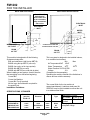
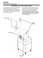
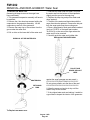
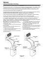
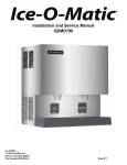
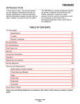
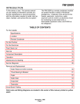
FM1202
INTRODUCTION
To the owner or user: The service manual you are
reading is intended to provide you, and the
maintenance or service technician, with the
information needed to install, start up, clean,
maintain, and service this ice system.
This machine is a modular ice system that fits a
variety of Scotsman ice storage bins.
It features: front service for the freezer, gearmotor,
control box, water reservoir, and bin control; an
electronic circuit for monitoring ice and water level;
a thermostatic expansion valve; and R-22 as the
refrigerant.
This manual covers both the "A" and the "B"
models, as designated by the last letter in the
model number.
TABLE OF CONTENTS
Installation
For the Installer
Specifications . . . . . . . . . . . . . . . . . . . . . . . . . . . . . . . 2
Location . . . . . . . . . . . . . . . . . . . . . . . . . . . . . . . . . . 3
Two units on one bin
. . . . . . . . . . . . . . . . . . . . . . . . . . . 4
For the Plumber . . . . . . . . . . . . . . . . . . . . . . . . . . . . . . . . . . 5
For the Electrician . . . . . . . . . . . . . . . . . . . . . . . . . . . . . . . . . 6
Final Check List . . . . . . . . . . . . . . . . . . . . . . . . . . . . . . . . . . 7
Start Up
. . . . . . . . . . . . . . . . . . . . . . . . . . . . . . . . . . . . . . . 8
Component Description . . . . . . . . . . . . . . . . . . . . . . . . . . . . . . . . . 9
Electrical Sequence . . . . . . . . . . . . . . . . . . . . . . . . . . . . . . . . . . . 12
Operation
. . . . . . . . . . . . . . . . . . . . . . . . . . . . . . . . . . . . . . . 13
Maintenance and Cleaning . . . . . . . . . . . . . . . . . . . . . . . . . . . . . . . . 15
Service Diagnosis
. . . . . . . . . . . . . . . . . . . . . . . . . . . . . . . . . . . 19
Removal and Replacement
Reservoir and Bin Controls . . . . . . . . . . . . . . . . . . . . . . . . . . . . 23
Bearing and Breaker . . . . . . . . . . . . . . . . . . . . . . . . . . . . . . . 24
Auger . . . . . . . . . . . . . . . . . . . . . . . . . . . . . . . . . . . . . . . 25
Water Seal
. . . . . . . . . . . . . . . . . . . . . . . . . . . . . . . . . . . 26
Evaporator
. . . . . . . . . . . . . . . . . . . . . . . . . . . . . . . . . . . 27
Fan Motor . . . . . . . . . . . . . . . . . . . . . . . . . . . . . . . . . . . . . 28
Refrigeration System . . . . . . . . . . . . . . . . . . . . . . . . . . . . . . . 29
Electronic Tester . . . . . . . . . . . . . . . . . . . . . . . . . . . . . . . . . . . . . 30
Parts lists and wiring diagrams are in the center of this manual, printed on yellow paper.
This manual was printed on recycled paper.
August 1993
Page 1
FM1202
FOR THE INSTALLER
BACK VIEW: AIR COOLED
BACK VIEW: WATER COOLED
Note: Allow 6"
behind and 6"
above either unit
for air circulation,
utility connections,
and service.
ELECTRICAL
INLET
ELECTRICAL
INLET
WATER
INLET
9.5"
5.25"
5.25"
7.3"
3"
3"
Condenser Inlet 3/8" FPT
WATER INLET
3/8" FLARE
2.9"
2.1"
Condenser Drain 1/2" FPT
3.4"
5.7"
DRAIN
3/4" FPT
DRAIN
3/4" FPT
4.9"
7.46"
This machine is designed to fit the following
Scotsman storage bins:
B90 and extensions (with bin top KBT18)
BH800 using bin top KBT15 (one unit).
BH800 (two units, no bin top required).
BH900 with KBT24 (one unit)
BH900 with KBT25 (two units side by side)
When installing a new system, check to be sure
that everything is on site before beginning:
Correct Bin
Correct Ice Machine
Correct Bin Top (if required)
All kits, legs, and information required for
the specific job.
Installation Limitations:
SPECIFICATIONS: ICE MAKER
This ice system is designed to be installed indoors,
in a controlled environment:
Min
Max
Air Temperature500F 1000F
1000F
Water Temperature
400F
Water Pressure 20 PSI 80 PSI
Voltage
-5%
+10%
(Compared to the nameplate)
Operating the machine outside of the limitations is
misuse and can void the warranty.
The normal finish for the ice machine is
enamel-sandalwood. A stainless steel panel kit,
SPKFM21 may be field installed to convert the unit
to a stainless steel finish.
Model Number
Dimensions
(w/o bin)
WxDxH
Basic
Electrical
Ice Type
Condenser
Type
FM1202AE-3A
FM1202WE-3A
FM1202AE-32A
FM1202WE-32A
21" x 24" x 27"
same
same
same
208-230/60/3
same
208-230/60/1
same
FLAKE
same
same
same
Air
Water
Air
Water
August 1993
Page 2
Refrigerant Charge*
Air Cooled 32 oz. R-22
Water
28 oz. R-22
Cooled
* Always go by the
nameplate charge.
9.43"
FM1202
FOR THE INSTALLER
Typical Storage Bin with Extension and Bin Top
Location:
After uncrating and inspection, the unit is ready for
installation. It is important that the machine be
installed in a location where it has enough space
around it to be accessible for service, and
minimum of 6" be allowed at the back for air
circulation on air cooled models. Try to avoid hot,
dirty and crowded locations. Be sure that the
location for the machine is within the
environmental limitations.
Storage Bin:
Tip the storage bin on its back, using parts of the
carton to protect the exterior finish. Install the legs
into the threaded holes in the bottom of the bin.
Turn the leg levelers all the way in preparation for
leveling later. Return the bin to the upright
position, remove paper covering the bin gasket.
Note: Do not push bin into position, but lift it there.
Pushing a bin, especially one with ice in it, can
cause damage to the legs and the leg mounts.
Install the appropriate bin top on the bin, according
to the instructions for the bin top.
Ice Maker:
The machine is heavy, so the use of a mechanical
lift is recommended for lifting the machine high
enough to install on top of the bin. After the unit is
placed on the bin, line it up so it is even with the
back side. Secure the machine to the bin with the
hardware provided with the machine.
Remove the front panel and remove any shipping
blocks.
Scotsman Ice Systems are designed and
manufactured with the highest regard for safety
and performance. They meet or exceed the
standards of UL, NSF and CSA.
Scotsman assumes no liability or responsibility of
any kind for products manufactured by Scotsman
that have been altered in any way, including the
use of any part and/or other components not
specifically approved by Scotsman.
Scotsman reserves the right to make design
changes and/or improvements at any time.
Specifications and design are subject to change
without notice.
August 1993
Page 3
FM1202
FOR THE INSTALLER: Location
DO NOT STACK ANYTHING IN
FRONT OF THE MACHINE(S)
TWO UNITS ON ONE BIN
ALLOW ROOM
FOR AIR
CIRCULATION
AND SERVICE
ACCESS
August 1993
Page 4
FM1202
FOR THE PLUMBER
CONFORM TO ALL APPLICABLE CODES
Water Inlet
Drains
Air Cooled Models: The recommended water
supply is clean, cold water. Use 3/8" O.D. copper
tubing, connect to the 3/8" male flare at the back of
the cabinet. Install a hand valve near the machine
to control the water supply.
Water Treatment: In most areas, a water filter of
some type will be useful. In areas where the water
is highly concentrated with minerals the water
should be tested by a water treatment specialist,
and the recommendations of the specialist
regarding filtration and/or treatment should be
followed.
Water Cooled Models: A separate 3/8" O.D.
copper line is recommended, with a separate hand
valve to control it. It is connected to a 3/8" FPT
condenser inlet at the back of the cabinet. The
water pressure to all lines must always be above
20 psig, and below 80 psig.
Air Cooled Models: There is one 3/4" FPT drain
at the back of the cabinet, the drain line is of the
gravity type, and 1/4 inch per foot fall is an
acceptable pitch for the drain tubing. There should
be a vent at the highest point of the drain line, and
the ideal drain receptacle would be a trapped and
vented floor drain. Use only 3/4" rigid tubing.
Water Cooled Models: In addition to the above
mentioned drain, a separate condenser drain must
be installed. Connect it to the 1/2" condenser
drain connection at the back of the cabinet.
Storage Bin: A separate gravity type drain needs
to be run, similar to the air cooled drain. Insulation
of this drain line is recommended.
AIR COOLED
MODELS
WATER
COOLED
FIELD
SUPPLIED
FILTER
CONDENSER
INLET
VENTED
DRAIN
HAND
VALVE
HAND
VALVE
WATER
FILTER
CONDENSER
DRAIN
VENTED
DRAIN
WATER
INLET
August 1993
Page 5
FM1202
FOR THE ELECTRICIAN
CONFORM TO ALL APPLICABLE CODES
The electrical power to the unit is supplied through
the junction box at the rear of the machine.
Check the nameplate (located on the back panel)
for the voltage requirements, and for the minimum
circuit ampacity. The machine requires a solid
chassis to earth ground wire.
The ice maker should be connected to its own
electrical circuit so it would be individually fused.
Voltage variation must remain within design
limitations, even under starting conditions.
All external wiring must conform to national,
state, and local electrical codes. The use of a
licensed electrician is required to perform the
electrical installation.
WATER COOLED
POWER
SUPPLY
AIR COOLED
August 1993
Page 6
FM1202
FOR THE INSTALLER
Final Check List
1. Is the ice system installed indoors in a location
where the air and water temperatures are
controlled, and where they do not exceed the
design limitations?
5. Is there a minimum of 6" clearance at the back
of the machine for proper service access and air
circulation?
6. Is the water pressure a minimum of 20 psig?
2. Is there an electrical service disconnect within
sight of the installed machine? Has the voltage
been checked, and compared to nameplate
requirements?
3. Have all the plumbing connections been made
and checked for leaks?
4. Has the machine and bin been leveled?
7. Has the machine been secured to the bin?
8. Is there clearance over the top of the machine
for service access?
9. Is there a water shut off valve installed near the
machine?
10. Have all of the shipping blocks been removed?
August 1993
Page 7
FM1202
START UP
Pre-Start Inspection
1. Remove the front and side service panels.
2. Check that the styrofoam shipping blocks have
been removed.
3. Inspect the interior of the machine for loose
screws or wires. Check that no refrigerant lines
are rubbing each other. Check that the fan blade
turns freely (air cooled).
4. Check that the unit is installed correctly
according to the final check list (page 7).
Start Up
1. Go through the prestart inspection.
2. Open the hand valve, observe that water enters
the water reservoir, fills the tube from the reservoir
to the evaporator, and then shuts off. Check for
leaks.
3. Switch the master switch on.
The electrical start up sequence is now on
automatic.
A. There should be a short (15 second) delay
before the gearmotor starts.
B. After the gearmotor starts, the compressor will
start.
4. On air cooled models, the condenser will begin
to discharge warm air, on water cooled models,
the water regulating valve will open, and warm
water will be discharged into the drain.
5. The unit should soon be making ice, if desired,
the low side pressure may be checked: it should
be 25 psig + or - 2 psig.
The suction line temperature at the compressor is
normally very cold, nearly to the point of frost up to
the compressor body, but not on it.
The air cooled discharge pressure will depend
upon air and water temperatures, but should be
between 200 psig and 280 psig.
The water cooled discharge pressure should be
constant at about 220 psig.
The above numbers are for new, clean machines,
you can expect to see some values higher, and
some lower between different units.
6. THERE ARE NO ADJUSTMENTS TO MAKE,
so replace the panels.
7. Clean and/or sanitize the storage bin interior,
wipe off the exterior with a clean, damp cloth.
8. Give the owner/user the service manual, instruct
him/her in the operation of the unit, and make sure
they know who to call for service.
9. Fill out the manufacturers registration card, and
mail it to the Scotsman Factory.
10. Fill out the field quality audit form, and mail it to
the Scotsman factory.
August 1993
Page 8
FM1202
COMPONENT DESCRIPTION
Control Box: Contains the electrical controls that
operate the machine.
High Pressure Cut Out Switch: A manual reset
switch sensing the high side refrigeration pressure.
It is set to shut the machine off if the discharge
pressure should ever exceed 400 psig.
Evaporator: A vertical stainless steel tube,
refrigerated, and water filled. In it there is a
stainless steel auger.
Compressor: The refrigerant vapor pump.
Reservoir: Float operated, it maintains the water
level in the evaporator at a constant level, it also
contains the water level sensor.
Water Level Sensor: Senses if there is water in
the reservoir to make ice out of. Will shut the
machine off it there is none.
Ice Discharge Chute: Directs the ice produced
by the evaporator into the storage bin.
Ice Level Sensor: An electronic "eye", it senses
the presence of ice in the bottom of the ice
discharge chute. Operates to turn the ice machine
on and off automatically as the level of ice in the
bin changes.
Gear Motor: An oil filled, speed reduction
gearbox, driving the auger.
Drain Tube: When uncapped and lowered, drains
the evaporator.
Condenser: Air or water cooled, where the heat
removed in ice making is discharged.
Expansion valve: The refrigerant metering
device.
AIR COOLED
WATER COOLED
CONTROL BOX
CONTROL BOX
RESERVOIR
CONDENSER
CONDENSER
EXPANSION
VALVE
EXPANSION
VALVE
DRAIN
TUBE
RESERVOIR
ICE CHUTE
ICE CHUTE
COMPRESSOR
ICE LEVEL
SENSORS
August 1993
Page 9
HIGH
PRESSURE
CUT OUT
ICE LEVEL
SENSORS
FM1202
COMPONENT DESCRIPTION: Control Box
Contactor: A definite purpose contactor
connecting the compressor and the fan motor to
the power supply.
Circuit Board, "B" Model: The circuit board
receives input signals from several electronic
sensors and translates them to control the
electrical power supply to various loads.
The sensors include:
• Electric eye to check the ice level in the bin.
• A thermistor to check the water level in the
reservoir.
The loads include:
• Compressor contactor
• Fan motor
• Auger drive motor.
Transformer: "A" Models Only. Supplies low
voltage to the circuit board.
Low Pressure Cut Out Switch: A manual reset
control that shuts off the ice machine when the low
side pressure drops below a preset point, 0-4 psig.
Potential Relay: The compressor start relay.
On/Off Switch: Manual control for the machine.
ON/OFF SWITCH
LOW
PRESSURE
CUT OUT
SWITCH
POTENTIAL
RELAY
CONTACTOR
TRANSFORMER
CIRCUIT
BOARD
• Amp draw of the gear motor.
August 1993
Page 10
FM1202
COMPONENT DESCRIPTION
Evaporator: A refrigerated vertical tube filled with
water and containing a water seal and auger.
Auger: A solid stainless steel double spiral auger,
it pushes the ice crystals up to the top of the
evaporator.
Water Seal: A two part "face" seal, the top half
rotating with the auger, the bottom half stationary,
the sealing action being where the two seal "faces"
meet.
Ice Sweep: A plastic cap with "fingers". It revolves
with the auger to "sweep" the ice into the ice chute.
Breaker (Divider): Where the ice is compressed
and much of the extra water is squeezed out of it
before it is discharged into the bin.
Motor: A split phase motor that drives the gear
reducer.
Thrust Bearing: As the ice is pushed up the
evaporator, the auger is thrust down, and pressure
from the auger thrust is taken up by this bearing.
ICE SWEEP
BEARING
BREAKER/DIVIDER
AUGER
EVAPORATOR
WATER
SEAL
MOTOR
August 1993
Page 11
FM1202
ELECTRICAL SEQUENCE: "A" Models
Refer the wiring diagram as needed.
If the machine is switched off at the master switch,
but is otherwise ready to go, switching the master
switch to on does the following:
• The bin empty light on the circuit board goes on
• There is a 15 second delay
• If there is enough water in the reservoir, the
more minutes, clearing out ice in the
evaporator, and then
• The auger motor relay opens, and the auger
circuit board will allow the machine to start up.
Start up consists of:
• The compressor relay and auger motor relay
become energized, connecting power to the
windings of the auger motor.
• The auger motor starts, and the centrifugal
switch closes, connecting power to the
compressor contactor coil.
• The contactor is energized, connecting power
to the compressor, and the compressor starts.
• As ice goes past the ice level sensors, the bin
empty light will stay on, and the machine will
continue to run, unless the ice stays between
the sensors for more than 15 seconds (bin full).
At that point, the bin empty light goes out, and
the machine shuts down.
Shut Down consists of:
• The compressor relay opens.
• The compressor contactor opens
• The compressor stops
• The auger motor is run by the circuit board for 2
motor stops.
If the ice level sensor is clear (bin empty) for more
than 15 seconds, the machine will start up again.
Another purpose of the circuit board is to turn the
machine off if there is not enough water in the
machine.
• When the water level in the reservoir falls
below the water level sensor, the machine will
"shut down"
• When the water refills the reservoir, the
machine will start up again.
Separate from the circuit board:
• If the high pressure control (cut out switch)
opens, the machine will stop immediately
(through the relays on the circuit board). it is a
manual reset.
• If the low pressure control (cut out switch)
opens, the machine will stop immediately
(through the relays on the circuit board). It is a
manual reset.
• If the spout switch opens,
the machine will stop
immediately, it must be manually reset.
• The master switch is the manual control for the
complete machine, but it is not a service
disconnect.
August 1993
Page 12
FM1202
OPERATION: Water
Water enters the machine through the 3/8" male
flare at the rear of the cabinet, goes to a strainer
and then to the water reservoir which it enters
through the float valve. The water then goes out
the bottom of the reservoir tank to the bottom of
the evaporator.
Reservoir overflow or evaporator condensation is
routed to the drain. Water cooled models have a
separate water circuit for the cooling water: it
enters the fitting at the rear, goes to the water
regulating valve, then to the water cooled
condenser and down the drain.
ADJUSTMENT OF WATER LEVEL
EVAPORATOR
DRAIN
SPOUT
SWITCH
RESERVOIR
WATER LEVEL
EVAPORATOR
ICE
CHUTE
STRAINER
DRAIN
WATER SCHEMATIC
August 1993
Page 13
FM1202
OPERATION: Refrigeration
Beginning at the compressor, the refrigerant is
compressed into a high temperature gas. The
discharge line directs this gas to the condenser.
At the condenser (air or water cooled) the gas is
cooled by either air or water and it then condenses
into a liquid. This high pressure liquid then goes
through the liquid line to the expansion valve.
The thermostatic expansion valve meters liquid
refrigerant into the evaporator, the volume of liquid
refrigerant depending upon the temperature of the
evaporator; warmer evaporators get more
refrigerant and colder evaporators get less.
At the evaporator, the refrigerant enters an area of
relatively low pressure, where it can easily "boil
off" or evaporate. As it evaporates, it absorbs heat
from the evaporator and whatever is in contact
with it (such as the water inside it). After the
evaporator, the refrigerant, now a low pressure
vapor, goes through the suction line back to
compressor, where the cycle is repeated.
Refrigeration Schematic
SUCTION LINE
CONDENSER
LIQUID
LINE
FAN
MOTOR
DISCHARGE
LINE
EVAPORATOR
THERMOSTATIC
EXPANSION
VALVE
GEAR
MOTOR
HIGH PRESSURE
CUT OUT SWITCH
COMPRESSOR
August 1993
Page 14
FM1202
SANITIZING AND CLEANING
//////////////////////////////////////////////////////////////////////////////////////////////////////////////////////////////////////////////////////////
A Scotsman Ice System represents a sizable investment of time and money in any company’s
business. In order to receive the best return for that investment, it MUST receive periodic
maintenance.
It is the USER’S RESPONSIBILITY to see that the unit is properly maintained. It is always
preferable, and less costly in the long run, to avoid possible down time by keeping it clean;
adjusting it as needed; and by replacing worn parts before they can cause failure. The following
is a list of recommended maintenance that will help keep the machine running with a minimum of
problems.
Maintenance and Cleaning should be scheduled at a minimum of twice per year.
///////////////////////////////////////////////////////////////////////////////////////////////////////////////////////////////////////////////////////////
Electrical shock hazard.
Electrical shock can
cause personal injury.
Disconnect power before
beginning to service
components.
ICE MAKING SYSTEM: In place cleaning
1. Check and clean any water treatment devices,
if any are installed.
2. Remove screws, and the front and top panels.
3. Move the ON-OFF switch to OFF.
4. Remove all the ice from the storage bin.
5. Remove the cover to the water reservoir and
block the float up.
6. Drain the water reservoir and freezer assembly
using the drain tube attached to the freezer water
inlet. Return the drain tube to its normal upright
position and replace the end cap.
7. Prepare the cleaning solution: Mix eight
ounces of Scotsman Ice Machine Cleaner with
three quarts of hot water. The water should be
between 90-115 degrees F.
8. Slowly pour the cleaning solution into the water
reservoir until it is full. Wait 15 minutes, then
switch the master switch to ON.
9. As the ice maker begins to use water from the
reservoir, continue to add more cleaning solution
to maintain a full reservoir.
10. After all of the cleaning solution has been
added to the reservoir, and the reservoir is nearly
empty, switch the master switch to OFF.
11. After draining the reservoir, as in step 6, wash
and rinse the water reservoir.
12. Remove the block from the float in the water
reservoir.
13. Switch the master switch to ON
14. Continue ice making for at least 15 minutes, to
flush out any cleaning solution. Check ice for acid
taste - continue ice making until ice tastes sweet.
DO NOT USE any ice produced from the
cleaning solution.
Be sure no ice remains in the bin.
15. Remove all ice from the storage bin.
16. Add warm water to the ice storage bin and
thoroughly wash and rinse all surfaces within the
bin.
17. Sanitize the bin interior with an approved
sanitizer using the directions for that sanitizer.
18. Replace the panels.
August 1993
Page 15
FM1202
MAINTENANCE AND CLEANING
A. Check the bearing by:
• removing the ice chute cover
Electrical shock hazard.
Electrical shock can
cause personal injury.
Disconnect power before
beginning to service
components.
1. The bin control uses devices that sense light,
therefore they must be kept clean enough so that
they can “see”. At least twice a year, remove the
bin control sensors from the base of the ice chute,
and wipe the inside clean, as illustrated.
2. The ice machine senses water level by a probe
• unscrewing the ice sweep
• removing the water shed
• unscrewing the breaker cover.
• unscrewing the auger stud
Inspect the assembly, looking for wear.
ICE LEVEL SENSORS:
SLIDE TO REMOVE
PULL UP TO
REMOVE PROBE
RESERVOIR
CLEAN THE
LIGHT SENSORS
CLEAN THE
WATER LEVEL
PROBE
See Removal and Replacement to replace
bearing or seals. Reverse to reassemble.
4. Check and tighten all bolts and screws.
ICE SWEEP
///////////////////////////////////////////
CAUTION: THE TIP IS
MADE OF GLASS
//////////////////////////////////////////
located in the water reservoir. At least twice a
year, the probe should be removed from the
reservoir, and the tip wiped clean of mineral
build-up.
3. The bearing in the breaker should also be
checked at least two times per year.
BREAKER
COVER
August 1993
Page 16
FM1202
MAINTENANCE: Air Cooled
Electrical shock hazard.
Electrical shock can
cause personal injury.
Disconnect power before
beginning to service
components.
5. Clean the air cooled condenser.
The air flow on this model is from front to back, so
the inside of the machine will have to be available
to clean the air cooled condenser. Use a vacuum
cleaner or coil cleaner if needed. Do NOT use a
wire brush.
A. Disconnect electrical power, and remove the
filter. The filter may be cleaned or replaced.
B. Clean the condenser: the condenser may
appear to be clean on the surface, but it can still
be clogged internally. Check with a flash light from
the front to see if light can be seen though the
condenser fins. Reverse to reassemble.
TO GAIN ACCESS TO CONDENSER SURFACE:
3. PULL FAN MOTOR ASSEMBLY UP AND OUT
1. REMOVE TOP PANEL
2. REMOVE TWO SCREWS & UNPLUG FAN MOTORS.
August 1993
Page 17
4. CLEAN CONDENSER FINS.
FM1202
MAINTENANCE AND CLEANING: Auger
In some areas, the water supply to the ice maker
will contain a high concentration of minerals, and
that will result in an evaporator and auger
ALLEN
becoming coated with these minerals, requiring a
SCREWS
more frequent removal than twice per year. If in
////////////WARNING////////////
doubt about the condition of the evaporator and
auger, the auger can be removed so the parts can The auger has sharp
edges, handle with care.
be inspected.
///////////////////////////////////////////
Note: Water filters can filter out suspended solids,
but not dissolved solids. “Soft” water may not be
the complete answer. Check with a water
BREAKER &
treatment specialist regarding water treatment.
BEARING &
AUGER
For more information on removal of these
ASSEMBLY
parts, see REMOVAL AND REPLACEMENT.
//////////////////////////////WARNING////////////////////////////
Switch off electrical power, and turn off the
water supply.
//////////////////////////////////////////////////////////////////////////
6. Drain the evaporator by lowering and uncapping
1. To remove the auger, remove the front and top
the evaporator drain hose.
panels.
7. Pull up to remove auger.
2. Remove 3 hex studs holding ice chute cover to
After the auger has been removed, allow the auger
ice chute, and remove cover.
to dry: if the auger is not bright and shiny, it must
3. Unscrew and remove ice sweep.
be cleaned.
4. Loosen band clamp under ice chute, and
Clean the auger and evaporator as required. DO
remove ice chute from evaporator.
NOT HONE THE EVAPORATOR.
5. Remove 4 allen screws holding breaker to
8. Replace the water seal.
evaporator.
9. Reverse to reassemble.
August 1993
Page 18
FM1202
SERVICE DIAGNOSIS: Condition - No Ice Being Produced
STATUS: NOTHING OPERATES
A. Check: Voltage to the unit, restore it if there is none. Compare to the nameplate.
B. Check: The master switch, switch ON if off.
C. Check: The 3 reset switches, (spout switch, high and low pressure): depress and release each
switch. If the still does not start, check: the spout switch; the high and the low side pressures.
D. Check the low pressure cut out, if closed, go to E; if it is open, it could be due to:
• Low refrigerant charge
• The auger not turning
• Restricted system
• TXV not opening
1. Check the low side pressure, the low pressure cut out opens at pressure below 4 psig.
If open, reset and:
a. Check if the auger is turning, if it is not, remove the gearbox and:
Check for internal damage, repair and replace in the machine.
b. Check for low charge, add some refrigerant, if the unit will operate,(normal
low side pressure being about 25 psig) stop and look for a leak, repair, replace the
drier, recover, evacuate, and weigh in the nameplate charge. If, with added charge, the unit
does not operate:
Check for a restricted system, replace the drier, recover, evacuate, and weigh in a
nameplate charge.
Check for a Thermostatic Expansion Valve that does not open, if defective,
replace it. Replace the drier, recover, evacuate, and weigh in the nameplate charge.
E. Check the high pressure cut out, if closed go to F, if open check
1. The pressure control opens at 400 psig. Check the high side pressure, reset the control,
and observe: on water cooled, that water soon begins to flow from the condenser drain;
or, on air cooled, that the fan is forcing air through the condenser. If the unit trips out on
pressures below 400 psig, replace the control. If the pressures rise above the trip out
point, and the unit shuts down:
a. Check for adequate water flow on water cooled, if adequate, clean the interior
of the condenser. If the pressures are still too high replace the water regulating valve.
b. Check for adequate air flow on air cooled. Clean the condenser and (if used) the
filter. If the air flow is poor because of the installation, advise the user that the unit
should be moved, or the air around it kept cooler.
Check the fan motor for tight bearings and proper rotation.
Check that the fan blades are clean, and the fan secure to the fan motor shaft.
F. Check the spout switch (a manual reset). It opens from excess pressure of ice inside the ice
chute: this should only happen when the machine does not shut off when the ice storage bin is full.
G. Check the water level in the reservoir. The machine will not run if there is not enough water in the
reservoir.
1. Restore/adjust water level. See the next step.
August 1993
Page 19
FM1202
SERVICE DIAGNOSIS: Condition - No Ice Being Produced
STATUS: NOTHING OPERATES
H. Check: The gear motor, if it will not run, the compressor will not run. If no power to it:
Check: The indicator lights on the circuit board, the bin empty light should be ON, the no water light
should be OFF .
1. If the bin empty and no water lights are off, check the transformer.
a. Transformer “load” side should have 12 to 15 volts. If not, check the “line” side. The line
side should have between 208-230 volts. If the line side has the correct voltage and the
load side does not, replace the transformer.
2. If the transformer is good, and the bin empty light is OFF, check the ice level sensors.
a. Remove sensors by sliding them sideways out of the ice chute. Visually inspect them,
clean if needed.
b. Look through the ice chute “eye” hole for something blocking the ice chute.
c. If the unit still does not run, replace the ice level sensors.
d. If the bin empty light is still OFF, check the circuit board.
1. Unplug “opto trans” and “LED” connectors from the circuit board.
2. Plug “opto trans” and “LED” connectors from the Scotsman Electronic Control
Tester Model NM1 into the circuit board.
a. Move the “bin full” switch on the tester to the full position. The bin full light
on the tester should be ON, if not, replace the circuit board.
If the bin full light on the tester is ON, move the tester switch to “bin empty”
the light on the tester should go OFF and the bin empty light on the circuit
board should go ON. If not, replace the circuit board. If it does as above,
and the machine still does not run, replace the ice level sensors.
3. If the transformer is fine, and the “no water” light is ON, check the water level sensor.
a. Check the water level in the reservoir, restore if low. If the water level is ok:
b. Remove the water level sensor from the reservoir and clean the tip if dirty.
CAUTION: THE TIP IS MADE OF GLASS
c. Replace the water level sensor. If the no water light is still on, check that the
"water sen" plug is firmly plugged into the circuit board.
d. If the no water light is still on,
1. Unplug the “water sen” connector from the circuit board.
2. Plug “water sen” connector from the Scotsman Electronic Control tester into
the circuit board.
a. Move the water switch on the tester to “no water” and the no water light
on the circuit board should go on. If not, replace the board.
b. Move the water switch to the “water” position, the no water light should
go off, if not, replace the circuit board.
c. If after the above, the machine still will not run, replace the water level
sensor
MORE INFORMATION ON THE TESTER MAY BE FOUND ON THE LAST PAGES OF THE MANUAL.
August 1993
Page 20
FM1202
SERVICE DIAGNOSIS: Condition - No Ice Produced
STATUS: GEARMOTOR OPERATES, COMPRESSOR DOES NOT
A. Check the compressor relay.
The relay is on the circuit board, if it does not supply power to the contactor coil, the
compressor will not run.
1. Check for power at the contactor coil, if none:
a. Check for power at the compressor relay at the circuit board.
If there is power at the relay, but none at the contactor coil,
Check for an open wire between the relay and the contactor.
2. Check the contactor coil. If the coil is open, replace the contactor.
3. Check the auger drive motor centrifugal switch. If, when the drive motor is running,
contact 4 (black wire removed) has no power, and all of the above switches have been
checked, replace the centrifugal switch, or the drive motor.
4. If the compressor relay on the circuit board has power on the NO contact, but not on the COM
replace the circuit board.
B. Check the compressor
1. Check the compressor start relay.
2. Check the start capacitor.
3. Check the windings of the compressor for open windings or shorts to ground.
Replace those items found defective.
August 1993
Page 21
contact,
FM1202
SERVICE DIAGNOSIS: Condition - Low Ice Production
STATUS: EVERYTHING IS OPERATING
A. Check the air cooled condenser for dirt. Clean as required. Check the head pressure on water
cooled. Adjust as required. If the head pressure is very high:
1. Air cooled. Check for high air temperatures, or restrictive air flow. Correct as needed.
2. Water cooled. Check for high water temperatures, or low water pressure.
Correct as needed.
3. The refrigerant may contain non condensable gases, recover, evacuate, and recharge per
nameplate.
B. Check the evaporator
1. Clean the evaporator, the mineral build up will adversely affect the ice machines production.
2. Check the evaporator for water leaks, replace the water seal if found to be leaking.
3. Check the low side pressure; normal is about 25 psig. If low, assume a refrigerant leak,
locate, repair and recharge.
If no leak, the TXV may be restricted, defective or not adjusted properly. If needed,
replace the TXV, recover, evacuate, and recharge per nameplate.
4. Check the insulation on the evaporator. It should be dry, with no wet spots or frost.
If the insulation has failed: replace the evaporator or add extra insulation in the form
of foam tape to the evaporator.
C. Check the compressor.
1. The compressor may be inefficient.
a. Check the amp draw, if low change the compressor.
b. if the amp draw is normal, pinch off the suction line to check the pull down capability
of the compressor. The compressor should pull down to 25 inches of vacuum and hold
there for three to five minutes.
.
August 1993
Page 22
FM1202
REMOVAL AND REPLACEMENT: Water Reservoir & Bin Controls
WATER RESERVOIR
1. Shut off the water supply to the ice maker.
2. Remove front panel and reservoir cover.
3. To remove float only, pry the mounting flanges
apart enough to lift one float pivot pin out of the
flange hole, and pull float up and out of the
reservoir.
4. To remove reservoir, disconnect water inlet
compression fitting at reservoir inlet.
5. Remove drain hose from reservoir.
6. Remove evaporator inlet hose from reservoir.
7. Remove mounting screws from reservoir
bracket, and remove reservoir from ice maker.
8. Reverse to reassemble.
ICE
CHUTE
FLOAT
ASSEMBLY
FLOAT
MOUNTING
FLANGES
SLIDE BIN
CONTROLS IN
AND OUT
BIN CONTROLS (Ice Level Sensors)
1. Disconnect electrical power.
2. Remove front panel.
3. Remove control box cover.
4. Locate ice chute, at the base of the chute, in
front of and behind it are two plastic bin control
mounts.
5. Slide each bin control to the left, and in the
control box, disconnect the electrical leads
connecting the bin control to the circuit board.
6. Reverse to reassemble, be certain that the bin
controls are aligned so that the ice level sensors
are visible (centered) through the holes in the ice
chute.
August 1993
Page 23
FM1202
REMOVAL AND REPLACEMENT: Bearing And Breaker
Note: Removal of the auger, water seal,
evaporator and gearmotor must begin at the top of
the assembly.
1. Remove panels and disconnect electrical
power.
Electrical shock hazard.
Electrical shock can
cause personal injury.
Disconnect power before
beginning to service
components.
2. Unscrew three studs and remove ice chute
cover.
3. Unscrew and remove ice sweep.
4. Remove insulation halves from outside of ice
chute, loosen band clamp under ice chute, lift up
and remove ice chute.
5. The breaker may be removed from the auger
and evaporator without disturbing the auger.
a. Unscrew breaker cover from breaker (left hand
threads)
b. Unscrew auger stud from top of auger.
Step 5-a
c. Unscrew 4 allen head cap screws holding
breaker to evaporator.
d. Lift up, and remove breaker/bearing assembly
from auger & evaporator.
6. Service the bearing. Check for rust, rough spots
and damage.
a. The bearing is pressed into the breaker, to
remove the bearing and replace it an arbor press
is needed.
b. Replace lower seals before installing new
bearing in breaker.
Note: seals must be pressed in with a tool pushing
against the outer edge only, they will not install by
hand.
Replace parts as required. Re-grease bearing with
Scotsman part no. 19-0609-01 bearing grease.
Replace top seal, and check the o-rings, replace if
cut or torn.
7. Reverse to reassemble: specific tools and
materials are required to install properly.
a. Add food grade grease such as Scotsman part
number 19-0569-01 to the seal area before
installing on the auger.
b. Check the seal to shaft areas for cuts, or rough
spots: none are permitted.
Step 5-b
Step 5-c and Step 6
BEARING
ICE
SWEEP
SEALS
AUGER
STUD
BREAKER
COVER
August 1993
Page 24
SLOTTED
COLLAR
FM1202
REMOVAL AND REPLACEMENT: Auger
To Remove the Auger:
Turn off the water to the machine, and unclip the
evaporator drain hose, pull it down and drain the
evaporator into the bin or a container.
1. The top panel must be removed.
Electrical shock hazard.
Electrical shock can
cause personal injury.
Disconnect power before
beginning to service
components.
2. Remove ice chute cover.
3. Unscrew ice sweep.
4. Loosen band clamp and remove ice chute body.
5. The auger and breaker/bearing may now be
removed as an assembly.
a. Unscrew 4 allen head cap screws holding
BREAKER
AND AUGER
ASSEMBLY
a. Unscrew breaker cover from breaker (left hand
threads)
b. Unscrew auger stud from top of auger.
c. Unscrew 4 allen head cap screws holding
breaker to evaporator.
d. Lift up & remove breaker from evaporator.
e. If the auger is stuck use a slide hammer type
puller to pull on the auger at the threaded hole.
The size of that hole is 5/8"-18.
Inspect the auger, the critical areas of the auger
are:
1. The auger body. It should be clean and
shining. Sometimes an auger will appear clean
when wet, but after it is dry it will be seen to be
stained. Scrub the auger with ice machine cleaner
and hot water.
///////////////////////////WARNING//////////////////////////////
Ice machine cleaner is an acid. Handle it with
extreme care, keep out of the reach of children.
//////////////////////////////////////////////////////////////////////////
2. The water seal area. Because the auger has
been removed, the water seal will have to be
replaced. Remove the water seal top half from the
auger, and inspect the auger for minerals, clean as
required.
/////////////WARNING///////////////
The auger has sharp
edges, handle with care.
////////////////////////////////////////////
SLIDE HAMMER
PULLER
THREAD INTO THE
AUGER HERE
breaker to evaporator.
b. Lift up on breaker and remove auger from
evaporator.
Note: If the auger is stuck, the breaker must
be removed from the auger.
The breaker may be removed from the auger and
evaporator without disturbing the auger.
August 1993
Page 25
FM1202
REMOVAL AND REPLACEMENT: Water Seal
To Remove the Water Seal:
(Assuming all steps to remove the auger have
been performed.)
1. The gearmotor/evaporator assembly will have to
be exposed.
2. Remove the 4 hex head cap screws holding the
evaporator to the gearmotor assembly. Lift the
evaporator up and off of the gearmotor.
3. Remove the snap ring or wire retainer from the
grove under the water seal.
4. Pull or drive out the lower half of the water seal.
1. Lubricate the water seal with water, and push
the water seal into the bottom of the evaporator
slightly past the grove for the snap ring.
2. Replace the snap ring and pull the water seal
down against it.
3. The part of the water seal that rotates with the
auger must also be replaced. Remove the old part
from the auger and clean the mounting area.
4. Place a small bead of food grade silastic sealant
(such as 732 RTV or Scotsman part number
19-0529-01) on the area of the auger where the
water seal is to be mounted.
5. Carefully push the water seal (rubber side
REPLACING THE WATER SEAL
REMOVAL OF THE WATER SEAL
PLACE FOOD
GRADE SEALANT
HERE
WATER SEAL
RETAINING
RING
against the auger shoulder and the silastic.)
/////////////////////////////CAUTION///////////////////////////
Do not get any silastic onto the face of the seal.
/////////////////////////////////////////////////////////////////////////
6. Allow the auger and seal to air dry until the
silastic is dry on the surface.
7. If the original water seal was leaking, it would be
a good idea to inspect the interior of the gearmotor.
To Replace the Water Seal:
August 1993
Page 26
FM1202
REMOVAL AND REPLACEMENT: Evaporator
Electrical shock hazard.
Electrical shock can cause
personal injury.
Disconnect power before
beginning to service
components.
To Reassemble the Evaporator and Auger
1. After the gearmotor has been inspected, fasten
the evaporator to the gear motor. Torque the bolts
to 110 inch pounds.
2. Lower the auger into the evaporator barrel,
slightly turning it to match up with the drive end.
Do Not Drop Into the Evaporator.
3. Complete the reassembly by reversing the
disassembly for the breaker & thrust bearing
assembly.
To Replace the Evaporator:
(Assuming all the steps for removal of the thrust
bearing, breaker, auger, and water seal have been
performed.)
1. Discharge the refrigerant from the ice maker.
2. Unsweat the refrigerant connections:
a) At the thermostatic expansion valve outlet.
///////////////////CAUTION/////////////////////
Heat sink the TXV body when
unsweating or resweating the
adjacent tubing.
////////////////////////////////////////////////////////
b) At the suction line at the joint
about 3" from the evaporator.
3. Remove the evaporator.
4. Unsweat the drier from the liquid
line.
5. After installing a new water seal
in the new evaporator (see "To
ICE CHUTE
Replace the Water Seal") sweat in
the new evaporator at the old tubing
connections.
6. Install an new drier in the liquid
line.
7. Evacuate the system until
dehydrated, then weigh in the
nameplate charge. Check for leaks.
8. Install auger, breaker, breaker
bearing assembly, and ice
discharge chute in reverse order of
disassembly.
ICE SWEEP
AUGER
EVAPORATOR
BEARING
BREAKER/DIVIDER
August 1993
Page 27
FM1202
REMOVAL AND REPLACEMENT
Electrical shock hazard.
Electrical shock can cause
personal injury.
Disconnect power before
beginning to service
components.
To Remove the Condenser Fan Motor Assembly
1. Remove top panel.
2. Unplug the two fan motor wire leads from the fan
motors.
3. Remove the two hex head bolts from the top end
of the fan motor assembly.
4. Lift up and pull out the fan motor assembly.
To Remove and Repair the Gearmotor
Assembly:
(Assuming that the procedures through removal of
the water seal have been performed.)
1. Remove the electrical wires from the gear drive
motor.
2. Unscrew the 4 cap screws holding the
gearmotor to the base of the machine.
3. Remove the gearmotor from the ice maker.
Bench test the gearmotor, check for oil leaks,
noise, and amp draw.
5. Repair as needed.
6. To reassemble: Place the fan motor assembly
lower flange holes over the two allen head cap
screws in the base, and reinstall the hex head bolts
at the top of the assembly. Plug the fan motors
back in, and replace the top panel.
August 1993
Page 28
FM1202
REMOVAL AND REPLACEMENT: Refrigeration System
General:
• Scotsman recommends that any work on the
refrigeration system only be done when it is
certain that the system needs repair.
• The access valves are at the front of the
cabinet. To use them, remove the cap from the
valve ports and the cap from the top of the valve
body. Attach gauge manifold and then use a
3/16" allen wrench to loosen the valve. Although
pressure readings may be taken with the valve
cracked open, several turns are required to
completely open the valve. Close valve and
replace caps when the job is finished.
• Refrigerant should not be added except as a
ALLEN
WRENCH
Torque to
6-8 ft. lbs.
Specifically:
Recover, reclaim or recycle refrigerant. Although
the method chosen is up to the service
company, Scotsman recommends reclaim.
There are various mechanical devices that may
be used to recycle refrigerant at the field level,
however, Scotsman requires that any refrigerant
placed into a Scotsman ice machine meet ARI
spec 700-88. Reclaim programs are available
thru most refrigerant wholesalers.
Use conservation minded service procedures:
• Refrain from checking refrigeration pressures
without reason. There are many ways to
determine the proper operation of a Scotsman
ice machine without using refrigerant gauges.
Visual inspection of the water system, amp
draw, voltage, and other techniques will lead
to proper diagnosis.
• If gauges must be used, do not always check
Cap, Torque
to 8-12 ft. lbs.
ACCESS VALVE
Cap, Torque
to 7-11 ft. lbs.
the high side pressure. If the condenser is
clean and seems to be operating correctly, it
most likely is. The low side pressure is much
more important on an ice machine than is the
high side.
• If gauges must be used, use very short
hoses. Minimal refrigerant discharged into the
hoses equals minimal refrigerant discharged
into the air.
• If using recycled refrigerant, it must meet ARI
way to determine the proper operation of the
product. If the system was low on refrigerant,
there is a leak, and it must be found and
repaired.
spec 700-88 or have been cleaned by a
machine capable of attaining ARI spec
700-88.
• Although this system uses R-22, it must not
be vented to the atmosphere.
• This system has a critical charge, it must be
recharged with the correct amount of
refrigerant as listed on the nameplate of the
ice machine, or performance will suffer.
• Anytime the refrigeration system has been
opened, the dryer should be replaced.
• When brazing the tubing connections to the
thermostatic expansion valve, the component
must be protected by heat sink material.
August 1993
Page 29
FM1202
CIRCUIT BOARD TESTING
///////////////////////////////////////////////////////////////////////WARNING//////////////////////////////////////////////////////////////////
These procedures require the machine to be connected to the power supply. The voltages of the
electronic circuit are very low, but HIGHER VOLTAGES ARE PRESENT IN THE UNIT. Do not
touch anything but the tester while the unit is being checked out. Make all connections to the
circuit board with the ELECTRICAL POWER OFF.
///////////////////////////////////////////////////////////////////////////////////////////////////////////////////////////////////////////////////////////
INSTRUCTIONS FOR USING TESTER (Optional, order part no. A33942-001)
(These instructions assume that the unit will not run, and prior investigation of electric power,
controls, and mechanical parts indicates that the electronic circuit may be at fault.)
If the "Reset" indicator (located in the "reset" switch) is off and the "NO WATER" indicator is lit,
but inspection shows that the water level in the reservoir is above the top of the water level
sensor, OR the "BIN EMPTY" indicator is off while inspection shows that the ice level sensors are
properly aligned, clean and not obstructed, use the tester as follows:
Bin Control Note: All testing is done with the
electrical power on, the master switch on, and all
reset switches “reset”.
1. Unplug “photo trans” and “LED” connectors from
the circuit board.
2. Plug “photo trans” and “LED” connectors from
the tester into the circuit board.
a. Move the “bin full” switch on the tester to Full.
The light on the tester should be ON.
If the light on the tester is not on, the circuit board
should be replaced.
b. If the light on the tester IS on, move the “bin
full” switch to Bin Empty. The light on the tester
should go OFF, and the Bin Empty light on the
circuit board should go ON.
If the Bin Empty light is ON, wait 10-20 seconds for
the machine to start, if the machine starts, replace
the ice level sensors.
If the Bin Empty light does not come ON, the
circuit board should be replaced.
PHOTO TRANS
LIGHT GOES
ON
LED
LIGHT
GOES OFF
LIGHT GOES
ON
SWITCH TO
“FULL”
SWITCH TO
“BIN EMPTY”
August 1993
Page 30
FM1202
CIRCUIT BOARD TESTING
Water Level
1. Unplug “water sen” connector from control
board.
2. Plug “water sen” connector from Scotsman
tester into circuit board.
a. Move “water” switch on tester to No Water
position. The No Water light on the circuit board
should go ON. If not, replace the circuit board.
b. Move the “water” switch on the tester to the
Water position. The No Water light on the board
should go OFF. If not replace the circuit board. If
the light does go off, replace the water level sensor.
If the Bin Empty light is ON, wait 10-20 seconds for
the machine to start. The machine should start.
LIGHT OFF
LIGHT ON
WATER SENS
SWITCH TO
“WATER”
SWITCH TO
“NO WATER”
August 1993
Page 31