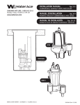
1
FM2402RH
TO THE OWNER OR USER:
The service manual you are reading is intended to
provide you, and the maintenance or service
technician, with the information needed to install,
start up, clean, maintain and service this ice
system.
The FM2402RH (remote high side) is the freezer
portion of a commercial ice machine. It is designed
to be connected to the condensing section of a
refrigeration system, specifically a supermarket
R-22 system. It consists of two evaporators, two
gearmotors, two liquid line valves, two control
boxes, two thermostatic expansion valves, and an
EPR valve.
For the Installer . . . . . . . . . . . . . . . . . . . . . . . . . . . . . . . . . . . . . . Page 2
For the Electrician
. . . . . . . . . . . . . . . . . . . . . . . . . . . . . . . . . . . Page 4
For the Plumber . . . . . . . . . . . . . . . . . . . . . . . . . . . . . . . . . . . . . Page 5
Final Check List . . . . . . . . . . . . . . . . . . . . . . . . . . . . . . . . . . . . . Page 6
Initial Start Up . . . . . . . . . . . . . . . . . . . . . . . . . . . . . . . . . . . . . . Page 7
Component Identification . . . . . . . . . . . . . . . . . . . . . . . . . . . . . . . . . Page 8
Electrical Sequence . . . . . . . . . . . . . . . . . . . . . . . . . . . . . . . . . . . Page 11
Operation
. . . . . . . . . . . . . . . . . . . . . . . . . . . . . . . . . . . . . . . Page 12
Maintenance and Cleaning . . . . . . . . . . . . . . . . . . . . . . . . . . . . . . . . Page 14
Service Diagnosis
. . . . . . . . . . . . . . . . . . . . . . . . . . . . . . . . . . . Page 17
Removal and Replacement
Bin Controls and Reservoir . . . . . . . . . . . . . . . . . . . . . . . . . . . . Page 20
Bearing and Breaker . . . . . . . . . . . . . . . . . . . . . . . . . . . . . . . Page 21
Auger . . . . . . . . . . . . . . . . . . . . . . . . . . . . . . . . . . . . . . . Page 22
Water Seal
. . . . . . . . . . . . . . . . . . . . . . . . . . . . . . . . . . . Page 23
Evaporator
. . . . . . . . . . . . . . . . . . . . . . . . . . . . . . . . . . . Page 24
Gearmotor . . . . . . . . . . . . . . . . . . . . . . . . . . . . . . . . . . . . . Page 25
Circuit Board Tester . . . . . . . . . . . . . . . . . . . . . . . . . . . . . . . . . . . Page 26
Parts lists and wiring diagrams are in the center of this manual, printed on yellow paper.
August 1992
Page 1
FM2402RH
FOR THE INSTALLER: Specifications
The FM2402RH is designed to fit several
Scotsman storage bins. In some cases a bin top
kit will be required.
Installation Limitations: The FM2402RH is
and performance. They meet or exceed the
standards of U.L., N.S.F., and C.S.A.
Scotsman assumes no liability or responsibility of
any kind for products manufactured by Scotsman
that have been altered in any way, including the
use of any parts and/or other components not
BACK VIEW
15.53"
3.1"
SUCTION LINE CONNECTION 7⁄8"
LIQUID LINE CONNECTI0N 1⁄2"
20.84"
9.43"
5.25"
3"
17.8"
18.8"
ELECTRICAL INLET
21.66"
POTABLE WATER INLET 3/8" FLARE
DRAIN 3/4" FPT
designed for indoor installations only. The machine
must also be in a controlled environment where
the air temperature does not fall below 500F., or
go above 1000F.
The water temperature must be between 400F.
and 1000F.
The electrical power supply must not drop below
-5% of the lowest nameplate voltage or go above
10% of the highest nameplate voltage.
SPECIFICATIONS:
Scotsman Ice Systems are designed and
manufactured with the highest regard for safety
specifically approved by Scotsman.
Scotsman reserves the right to make design
changes and/or improvements at any time.
Specifications and designs are subject to change
without notice.
Model Number
Dimensions (w/o Bin)
H" x W" D"
Ice
Type
Basic
Electrical
Minimum
Circuit
Ampacity
Maximum
Fuse
Size
BTU’s
Required
FM2402RH-32A
27" X 42" X 24"
Flake
208-230/60/1
2.7
15
16,000
August 1992
Page 2
FM2402RH
FOR THE INSTALLER
Select the Location:
The unit can only be installed indoors
within the limitations described on
TYPICAL INSTALLATION: ALLOW ROOM FOR SERVICE ACCESS
page 2.
The ice machine will have to be
connected to the buildings R-22
refrigeration system, check to be
FM2402RH
sure that the system has enough
extra capacity to handle a minimum
of additional 16,000 BTU’s per hour
@ 1100F. liquid line temperature.
Assume a 00F. evaporator
temperature.
Storage Bin:
Scotsman’s B90 will be the
presumed bin of choice. If using the
bin extension, install heavy duty leg
kit KLP4 and place the bin into
position.
Remove the paper tape from the bin
edge gasket, and install the bin
extension onto the B90.
Remove the paper tape from the bin
extension top edge, and using a
mechanical lift, install the FM2402RH
onto the top of the storage bin
BIN
assembly.
EXTENSION
Fasten the ice machine to the bin
using (4) 5/15-18 2.5" cap screws.
Level the assembly by:
B90 STORAGE
BIN
a. Turning the leg levelers in or out
on the standard legs.
b. Use shims under the heavy duty
legs of the KLP4.
Locate the Nameplate: The
nameplate is located on the back
panel of the machine, and contains
the electrical characteristics
particular to the unit being installed.
Refrigeration Installation:
//////////////////////////////Caution/////////////////////////////
The skills of a refrigeration technician are required
Connect to a R-22 system only.
to connect the ice machine to the buildings
refrigeration system.
////////////////////////////////////////////////////////////////////////
Local Codes must be observed.
A P-trap should be installed where there will be
more than 10’ of vertical rise in the suction line.
August 1992
Page 3
FM2402RH
FOR THE ELECTRICIAN
CONFORM TO ALL APPLICABLE CODES
Electrical Connections:
Locate the nameplate for the current
requirements, and then determine the
wire size and type per the National
Electric Code. The machine requires a
solid chassis to earth ground wire.
Refer to the wiring diagram. The ice
machine should be connected to its
own electrical circuit, and be
individually fused.
Voltage, when the unit is under full
load, must remain within the limitations
listed on page 2.
LOW VOLTAGE CAN CAUSE
EQUIPMENT MALFUNCTION
AND/OR DAMAGE
All external wiring should conform to
the National, State, and local electrical
codes. Usually the services of a
licensed electrician will be required.
DETAIL OF
JUNCTION BOX
JUNCTION
BOX
POWER SUPPLY
August 1992
Page 4
FM2402RH
FOR THE PLUMBER
CONFORM TO ALL APPLICABLE CODES
Water Supply:
The recommended water supply line is 3/8" O.D.
copper tubing, with a minimum operation pressure
of 20 PSIG, and a maximum of 120 PSIG.
Connect to cold water using the male flare
connection at the back of the machine. Install a
shut off valve in an accessible space between the
ice maker and the water supply.
All drains are of the gravity type, and must have a
minimum of 1/4" fall per foot of horizontal run. The
drains must be installed to conform to local
plumbing codes. The use of a vent at the machine
and at the bin will allow the system to drain
properly. Use only rigid tubing for drains; insulation
of the bin drain is recommended.
Drain System:
3/8" MALE FLARE
3/4" FPT
SHUT OFF
VALVE
VENT THIS DRAIN
FIELD
SUPPLIED
WATER FILTER
WATER INLET
BIN DRAIN
FLOOR DRAIN
August 1992
Page 5
FM2402RH
FOR THE INSTALLER: Final Check List
1. Is the unit installed where the air and water
temperatures are within and will remain within the
limitations for the unit?
2. Is there 6" clearance at the rear of the machine
for utility connections?
3. Has the water supply line be checked for
pressures between 20 and 120?
4. Has the unit been leveled?
5. Has the shipping material been removed from
inside the cabinet?
6. Have the electrical connections been made?
7. Have the drains been installed and checked for
leaks?
8. Has the refrigeration supply been installed and
checked for leaks?
9. Has the bin and cabinet been wiped clean or
sanitized?
10. Has the warranty registration card been
properly filled out and mailed to Scotsman?
11. Has the owner been given the service manual
and been instructed on how to maintain the
icemaker?
13. Has the owner been given the name and
telephone number of the local Scotsman service
agency?
August 1992
Page 6
FM2402RH
INITIAL START UP
1. Remove the top and front panels.
2. Open the water valve, and observe that the two
float reservoirs fill up with water and shut off.
3. Switch on the electrical power.
7. Switch on the other master switch, observe that:
The liquid line valve opens
The gearmotor runs
Within a short time, that side of the machine
begins to make ice.
Water flows from the water reservoir, and the float
drops, letting in more water.
4. Open the hand valves (in the liquid lines).
5. Open the ball valves (in the suction lines).
6. Switch on one master switch, and observe:
The liquid line valve opens
The gearmotor runs
Within a short time, that side of the machine
begins to make ice.
Water flows from the water reservoir, and the float
drops, letting in more water.
8. With both sides operating, the sight glass
should remain full, and the low side pressure will
be about 24 psig, + or - 2 psig. Gearmotor amp
draw should not exceed the nameplate rating.
9. Check the system very carefully for any
refrigerant leaks, repair as needed.
August 1992
Page 7
FM2402RH
COMPONENT IDENTIFICATION
Liquid line valve(s)
These valves operate to turn the ice making
process on and off.
When the ice level drops in the ice chute, the ice
level sensor will cause the circuit board to close
the liquid line relay, which energizes the liquid line
valve for that side of the system. The liquid line
valve opens, and liquid refrigerant flows to the
thermostatic expansion valve.
Thermostatic Expansion Valve
The metering device of each system, the valve(s)
sense the temperature of the suction line and vary
the amount of liquid refrigerant that passes
through the valve into the evaporator, thus
maintaining a constant level of refrigeration. TXV’s
are factory set. Do not adjust unnecessarily.
DO NOT ADJUST THE TXV UNTIL THE EPR
HAS BEEN SET.
The superheat setting is 4-80F. Measure the
temperature of the evaporator outlet at the TXV
bulb, and check the low side pressure at the EPR
valve (about 24 PSIG). Convert the pressure to
temperature (using a temperature pressure chart)
and subtract the amount from the outlet
temperature. The result is the superheat. Use an
electronic thermometer.
EPR: Evaporator Pressure Regulator Valve
This valve maintains a constant pressure on it’s
inlet (evaporators) side regardless of the pressure
on the outlet (suction) side. The EPR is factory set,
adjust only if needed. After adjusting check TXV
superheat.
Evaporators:
Where the water is frozen into ice crystals. As the
water cools, it begins to turn into ice, and the
slowly turning auger lifts the ice, as it is being
made, and forces it up and out of the "breaker" or
spout where the extra water is compressed out of
the ice. The ice then drops through the chute, into
the storage bin.
EPR VALVE
THERMO VALVE
LIQUID LINE
VALVE
THERMO
VALVE
EVAPORATOR
August 1992
Page 8
FM2402RH
COMPONENT DESCRIPTION: Control Box
Circuit Board: Controlling the ice machine
through sensors and relays. The sensors are: ice
level, and water level. The relays are for the gear
motor (with a built in time delay to clear the
evaporator of ice when the unit turns off) and for
the liquid line valve.
Transformer: Supplies low voltage to the circuit
board.
On/Off Switch: Manual control for that side of the
machine.
ON/OFF SWITCH
TERMINAL STRIP
TRANSFORMER
CIRCUIT
BOARD
August 1992
Page 9
FM2402RH
COMPONENT DESCRIPTION: Evaporator
Evaporator: A refrigerated vertical tube filled
water and containing a water seal and auger.
Auger: A solid stainless steel double spiral auger,
it pushes the ice crystals up to the top of the
evaporator.
Water Seal: A two part "face" seal, the top half
rotating with the auger, the bottom half stationary,
the sealing action being where the two seal "faces"
meet.
Ice Sweep: A plastic cap with "fingers". It revolves
with the auger to "sweep" the ice into the ice chute.
Divider: Where the ice is compressed and much
of the extra water is squeezed out of it before it is
Motor: A motor that drives the gear reducer.
Bearing: As the ice is pushed up the evaporator,
the auger is thrust down, and pressure from the
auger thrust is taken up by this bearing.
ICE SWEEP
BEARING
DIVIDER
EVAPORATOR
AUGER
WATER
SEAL
MOTOR
discharged into the bin.
August 1992
Page 10
FM2402RH
ELECTRICAL SEQUENCE
Refer the wiring diagram as needed.
Each system is separate
If the machine is switched off at the master switch,
but is otherwise ready to go, switching the master
switch to on and pressing the start reset switch
does the following:
• The bin empty light on the circuit board goes on
• There is a 15 second delay
• If there is enough water in the reservoir, the
Shut Down consists of:
• The liquid line relay opens.
• The liquid line valve closes
• Ice making stops
• The auger motor is run by the circuit board for
2.5 more minutes, clearing out ice in the
evaporator, and then
• The auger motor relay opens, and the auger
circuit board will allow the machine to start up.
Start up consists of:
• The liquid line relay and auger motor relay
become energized, connecting power to the
windings of the auger motor.
• The auger motor starts, and the centrifugal
switch closes, connecting power to the liquid
line valve coil.
• The
liquid line valve opens, and the refrigerant
flows to the thermostatic expansion valve and
into the evpaorator.
• As ice goes past the ice level sensors, the bin
empty light will stay on, and the machine will
continue to run, unless the ice stays between
the sensors for more than 15 seconds (bin full).
At that point, the bin empty light goes out, and
the machine shuts down.
motor stops.
If the ice level sensor is clear (bin empty) for more
than 15 seconds, the machine will start up again.
Another purpose of the circuit board is to turn the
machine off if there is not enough water in the
machine.
• When the water level in the reservoir falls
below the water level sensor, the machine will
"shut down"
• When the water refills the reservoir, the
machine will start up again.
Separate from the circuit board:
• If the spout switch opens, the machine will stop
immediately (through the relays on the circuit
board). It must be manually reset at the reset
switch.
• The master switch is the manual control for
each system, but it is not a service disconnect.
August 1992
Page 11
FM2402RH
OPERATION
Water
Water enters the machine through the 3/8" male
flare at the rear of the cabinet, goes to the water
reservoir which it enters through the float valve.
The water then goes out the bottom of the
reservoir tank to the bottom of the evaporator.
Reservoir overflow or evaporator condensation is
routed to the drain.
ADJUSTMENT OF THE WATER
RESERVOIR
WATER SCHEMATIC
WATER INLET
WATER
LEVEL
DRAIN
RESERVOIR
EVAPORATOR
WATER INLET
DRIP PAN DRAIN
August 1992
Page 12
FM2402RH
OPERATION: Refrigeration
The remote high side
supplies high pressure
liquid R-22 to the liquid
line connection on the
ice machine. After the
sight glass, there are
two separate liquid lines,
each leading to a liquid
line valve. When the
individual ice level
sensor causes the circuit
board to energize the
liquid line valve, the
valve opens, allowing
the liquid refrigerant to
enter that expansion
valve. The thermostatic
expansion valve meters
the liquid refrigerant into
LIQUID
LINE
SIGHT GLASS
HAND VALVE
LIQUID LINE
VALVE
THERMO VALVE
EVAPORATORS
BALL VALVES
SUCTION LINE
EPR VALVE
August 1992
Page 13
the evaporator, where it
boils off (evaporates)
and absorbs heat. It
then moves through the
ball valve and into the
evaporator pressure
regulator valve, or EPR.
The EPR keeps the
evaporator pressure
above a predetermined
point, even though the
suction line pressure of
the remote high side
system may vary. The
refrigerant, now a low
pressure gas, moves
into the suction line of
the remote high side
system.
FM2402RH
MAINTENANCE AND CLEANING
///////////////////////////////////////////////////////////////////////////////////////////////////////////////////////////////////////////////////////////
A Scotsman Ice System represents a sizable investment of time and money in any company’s
business. In order to receive the best return for that investment, it MUST receive periodic
maintenance.
It is the USER’S RESPONSIBILITY to see that the unit is properly maintained. It is always
preferable, and less costly in the long run, to avoid possible down time by keeping it clean;
adjusting it as needed; and by replacing worn parts before they can cause failure. The following
is a list of recommended maintenance that will help keep the machine running with a minimum of
problems.
Maintenance and Cleaning should be scheduled at a minimum of twice per year.
///////////////////////////////////////////////////////////////////////////////////////////////////////////////////////////////////////////////////////////
//////////////////////////WARNING/////////////////////////////
Electrical power will be ON when doing in
place cleaning. Switch it OFF before
completing the cleaning procedures.
/////////////////////////////////////////////////////////////////////////
ICEMAKING SYSTEM: In place cleaning
1. Check and clean any water treatment devices,
if any are installed.
2. Pull out and remove the front panel.
3. Move the ON-OFF switch to OFF.
4. Remove all the ice from the storage bin.
5. Remove the cover to the water reservoir and
block the float up.
6. Drain the water reservoir and freezer assembly
using the drain tube attached to the freezer water
inlet. Return the drain tube to its normal upright
position and replace the end cap.
//////////////////////////WARNING//////////////////////////////
Scotsman Ice Machine Cleaner contains
Phosphoric and Hydroxyacetic acids. These
compounds are corrosive and may cause
burns. If swallowed, DO NOT induce vomiting.
Give large amounts of water or milk. Call
Physician immediately. In case of external
contact, flush with water. KEEP OUT OF THE
REACH OF CHILDREN.
//////////////////////////////////////////////////////////////////////////
7. Prepare the cleaning solution: Mix eight
ounces of Scotsman Ice Machine Cleaner with
three quarts of hot water. The water should be
between 90-115 degrees F.
8. Slowly pour the cleaning solution into the water
reservoir until it is full. Wait 15 minutes, then
switch the master switch to ON.
9. As the ice maker begins to use water from the
reservoir, continue to add more cleaning solution
to maintain a full reservoir.
10. After all of the cleaning solution has been
added to the reservoir, and the reservoir is nearly
empty, switch the master switch to OFF.
11. After draining the reservoir, as in step 6, wash
and rinse the water reservoir.
12. Remove the block from the float in the water
reservoir.
13. Switch the master switch to ON
14. Continue ice making for at least 15 minutes, to
flush out any cleaning solution. Check ice for acid
taste - continue icemaking until ice tastes sweet.
///////////////////////////////WARNING/////////////////////////
DO NOT USE any ice produced from the
cleaning solution.
Be sure no ice remains in the bin.
//////////////////////////////////////////////////////////////////////////
15. Remove all ice from the storage bin.
16. Add warm water to the ice storage bin and
thoroughly wash and rinse all surfaces within the
bin.
17. Sanitize the bin interior with an approved
sanitizer using the directions for that sanitizer.
18. Replace the front panel.
August 1992
Page 14
FM2402RH
MAINTENANCE
////////////////////////////WARNING////////////////////////////
Disconnect electrical power before beginning.
/////////////////////////////////////////////////////////////////////////
1. The bin control uses devices that sense light,
therefore they must be kept clean enough so that
they can "see". At least twice a year, remove the
bin control sensors from the base of the ice chute,
and wipe the inside clean, as illustrated.
2. The ice machine senses water level by a probe
located in the water reservoir. At least twice a
year, the probe should be removed from the
SLIDE ICE
LEVEL
CONTROLS OUT
OF CHUTE
CLEAN THE ICE
LEVEL CONTROL
SENSORS
RESERVOIR
4. Check and tighten all bolts and screws.
CLEAN THE
WATER LEVEL
SENSOR
/////////////////////////////
CAUTION: THE
TIMP IS MADE OF
GLASS
///////////////////////////////
reservoir, and the tip wiped clean of mineral
buildup.
3. The bearing in the breaker should also be
checked at least two times per year.
Check the bearing by:
• removing the ice chute cover
• unscrewing the ice sweep
• removing the water shed
• unscrewing the breaker cover
• unscrewing the auger stud
Inspect the assembly, looking for wear.
See Removal and Replacement to replace bearing
or seals. Reverse to reassemble.
August 1992
Page 15
FM2402RH
CLEANING
In some installations the water supply to the
icemaker will be so concentrated with dissolved
minerals, (such as calcium carbonate) that as ice
is made, the evaporator and auger become
coated with the minerals, requiring a more frequent
cleaning than twice per year. If in doubt about the
condition of the evaporator and auger, the auger
can be removed so the parts can be inspected.
Note: Water filters can filter out suspended solids,
but not dissolved solids. "Soft" water may not be
the complete answer. Check with a water
treatment specialist regarding water treatment.
DIVIDER, AUGER
AND SLOTED
COLLAR
ALLEN HEAD
SCREWS
Switch off electrical power, and shut off the
water suplly.
For more information on removal of these
parts, see REMOVAL AND REPLACEMENT.
1. To remove the auger, remove front and top
panel. If top panel cannot be removed, or if there is
less than 6" clearance over the top of the machine,
the gearmotor/evaporator may be slid out for
service access. See Removal And Replacement.
2. Remove 3 hex studs holding ice chute cover to
ice chute, and remove cover.
3. Unscrew and remove ice sweep.
4. Loosen band clamp under ice chute, and
remove ice chute from evaporator.
5. Remove 4 allen head screws holding breaker to
evaporator.
6. Pull up on breaker to remove auger.
Allow the auger to dry, the stainless steel of the
auger and evaporator must be clean and bright.
Clean the auger and evaporator as required. DO
NOT HONE THE EVAPORATOR.
7. Replace the water seal.
8. Reverse to reassemble.
August 1992
Page 16
FM2402RH
SERVICE DIAGNOSIS: Condition - No Ice Being Produced
STATUS: NOTHING OPERATES
A. Check: Voltage to the unit, restore it if there is none. Compare to the nameplate.
B. Check: The master switch, switch ON if off.
C. Check the spout switch. It opens from excess pressure of ice inside the ice chute: this should only
happen when the machine does not shut off when the ice storage bin is full. This switch must be
manually reset.
D. Check the water level in the reservoir. The machine will not run if there is not enough water in the
reservoir.
1. Restore/adjust water level. See the next step.
August 1992
Page 17
FM2402RH
SERVICE DIAGNOSIS: Condition - No Ice Being Produced
STATUS: NOTHING OPERATES
F. Check: The gear motor, if it will not run, the liquid line valve will not open. If no power to it:
Check: The indicator lights on the circuit board, the bin empty light should be ON, the no water light
should be OFF .
1. If the bin empty and no water lights are off, check the
transformer.
a. Transformer "load" side should have 12 to 15 volts. If not, check the "line" side. The line
side should have between 208-230 volts. If the line side has the correct voltage and the
load side does not, replace the transformer.
2. If the transformer is good, and the bin empty light is OFF, check the ice level sensors.
a. Remove sensors by sliding them sideways out of the ice chute. Visually inspect them,
clean if needed.
b. Look through the ice chute "eye" hole for something blocking the ice chute.
c. If the unit still does not run, replace the ice level sensors.
d. If the bin empty light is still OFF, check the circuit board.
1. Unplug "opto trans" and "LED" connectors from the circuit board.
2. Plug "opto trans" and "LED" connectors from the Scotsman Electronic Control
Testor Model NM1 into the circiut board.
a.Move the "bin full" switch on the tester to the full position. The bin full light
on the tester should be ON, if not, replace the circuit board.
If the bin full light on the tester is ON, move the tester switch to "bin empty"
the light on the tester should go OFF and the bin empty light on the circuit
board should go ON. If not, replace the circuit board. If it does as above,
and the machine still does not run, replace the ice level sensors.
3. If the transformer is fine, and the "no water" light is ON, check the water level sensor.
a. Check the water level in the reservoir, restore if low. If the water level is ok:
b. Remove the water level sensor from the reservoir and clean the tip if dirty.
CAUTION: THE TIP IS MADE OF GLASS
c. Replace the water level sensor. If the no water light is still on, check that the
"water sen" plug is firmly plugged into the circuit board.
d. If the no water light is still on,
1. Unplug the "water sen" connector from the circuit board.
2. Plug "water sen" connector from the Scotsman Electronic Control tester into
the circuit board.
a. Move the water switch on the tester to "no water" and the no water light
on the circuit board should go on. If not, replace the board.
b. Move the water switch to the "water" position, the no water light should
go off, if not, replace the circuit board.
c. If after the above, the machine still will not run, replace the water level
sensor
August 1992
Page 18
FM2402RH
SERVICE DIAGNOSIS:
STATUS: GEARMOTOR OPERATES, BUT NO ICE IS MADE
A. Check the liquid line valve relay.
The relay is on the circuit board, if it does not supply power to the liquid line valve, the
valve will not open.
1. Check for power at the valve coil, if none:
a. Check for power at the liquid line valve relay at the circuit board.
If there is power at the relay, but none at the liquid line valve coil,
Check for an open wire between the relay and the valve.
2. Check the valve coil. If the coil is open, replace the liquid line valve.
3. Check the auger drive motor centrifugal switch. If, when the drive motor is running,
contact 4 (black wire removed) has no power, and all of the above switches have been
checked, replace the centrifugal switch, or the drive motor.
4. If the liquid line valve relay on the circuit board has power on the NO contact, but not on the COM
contact, replace the circuit board.
August 1992
Page 19
FM2402RH
REMOVAL AND REPLACEMENT
WATER RESERVOIR
1. Shut off the water supply to the icemaker.
2. Remove front panel and reservoir cover.
3. To remove float only, pry the mounting flanges
apart enough to lift one float pivot pin out of the
flange hole, and pull float up and out of the
reservoir.
4. To remove reservoir, disconnect water inlet
compression fitting at reservoir inlet.
5. Remove drain hose from reservoir.
6. Remove evaporator inlet hose from reservoir.
7. Remove mounting screws from reservoir
bracket, and remove reservoir from icemaker.
8. Reverse to reassemble.
BIN CONTROLS (Ice Level Sensors)
1. Disconnect electrical power.
2. Remove front panel.
3. Remove control box cover.
4. Locate ice chute, at the base of the chute, in
front of and behind it are two plastic bin control
mounts.
5. Slide each bin control to the left, and in the
control box, disconnect the electrical leads
connecting the bin control to the circuit board.
6. Reverse to reassemble, be certain that the bin
controls are aligned so that the ice level sensors
are visible (centered) through the holes in the cube
chute.
CHUTE
SLIDE BIN
CONTROLS
IN AND OUT
FLOAT
ASSEMBLY
FLOAT
MOUNTING
FLANGES
August 1992
Page 20
FM2402RH
REMOVAL AND REPLACEMENT: Bearing And Breaker
Note: Removal of the auger, water seal,
evaporator and gearmotor must begin at the top of
the assembly.
To Remove the Breaker Bearing Assembly:
//////////////////////////////WARNING//////////////////////////
Disconnect the electrical power to the machine
at the building source BEFORE proceeding
with any repair.
//////////////////////////////////////////////////////////////////////////
1. Remove panels and disconnect electrical power.
2. Unscrew three studs and remove ice chute
cover.
3. Unscrew and remove ice sweep.
4. Remove insulation halves from outside of ice
chute, loosen band clamp under ice chute, lift up
and remove ice chute.
5. The breaker may be removed from the auger
and evaporator without disturbing the auger.
a. Unscrew breaker cover from breaker (left hand
threads)
b. Unscrew auger stud from top of auger.
c. Unscrew 4 allen head cap screws holding
breaker to evaporator.
d. Lift up, and remove breaker/bearing assembly
from auger & evaporator.
6. Service the bearing. Check for rust, rough spots
and damage.
a. The bearing is pressed into the breaker, to
remove the bearing and replace it an arbor press
is needed.
b. Replace lower seals before installing new
bearing in breaker.
Note: seals must be pressed in with a tool pushing
against the outer edge only, they will not install by
hand.
Replace parts as required. Re-grease bearing with
Scotsman part no. 19-0609-01 bearing grease.
Replace top seal, and check the o-rings, replace if
cut or torn.
7. Reverse to reassemble: specific tools and
materials are required to install properly.
a. Add food grade grease such as Scotsman part
number 19-0569-01 to the seal area before
installing on the auger.
b. Check the seal to shaft areas for cuts, or rough
spots: none are permitted.
Step 5-b
Step 5-c and Step 6
BEARING
SEALS
SLOTTED
COLLAR
AUGER
STUD
DIVIDER
August 1992
Page 21
FM2402RH
REMOVAL AND REPLACEMENT
///////////////////////////WARNING/////////////////////////////
Disconnect electrical power. Handle the auger
with care: it has sharp edges.
//////////////////////////////////////////////////////////////////////////
To Remove the Auger:
Turn off the water to the machine, and unclip the
evaporator drain hose, pull it down and drain the
evaporator into the bin or a container.
1. The top panel must be removed.
2. Remove ice chute cover.
3. Unscrew ice sweep.
4. Loosen band clamp and remove ice chute body.
5. The auger and breaker/bearing may now be
removed as an assembly.
a. Unscrew 4 allen head cap screws holding
breaker to evaporator.
b. Lift up on breaker and remove auger from
evaporator.
Note: If the auger is stuck, the breaker must be
removed from the auger.
The breaker may be removed from the auger and
Inspect the auger, the critical areas of the auger
are:
1. The auger body. It should be clean and
shining. Sometimes an auger will appear clean
when wet, but after it is dry it will be seen to be
stained. Scrub the auger with ice machine cleaner
and hot water.
///////////////////////////WARNING//////////////////////////////
Ice machine cleaner is an acid. Handle it with
extreme care, keep out of the reach of children.
//////////////////////////////////////////////////////////////////////////
2. The water seal area. Because the auger has
been removed, the water seal will have to be
replaced. Remove the water seal top half from the
auger, and inspect the auger for minerals clean as
required.
DIVIDER
AND
AUGER
ASSEMBLY
SLIDE HAMMER
PULLER
THREAD INTO THE
AUGER HERE
evaporator without disturbing the auger.
a. Unscrew breaker cover from breaker (left hand
threads)
b. Unscrew auger stud from top of auger.
c. Unscrew 4 allen head cap screws holding
breaker to evaporator.
d. Lift up and remove breaker from evaporator.
e. If the auger is stuck use a slide hammer type
puller to pull on the auger at the threaded hole.
The size of that hole is 5/8"-18.
August 1992
Page 22
FM2402RH
REMOVAL AND REPLACEMENT
/////////////////////////////WARNING///////////////////////////
Disconnect the electrical power to the machine
at the building source BEFORE proceeding
with any repair.
//////////////////////////////////////////////////////////////////////////
To Remove the Water Seal:
(Assuming all steps to remove the auger have
been performed.)
1. The gearmotor/evaporator assembly will have to
be exposed.
2. Remove the 4 hex head cap screws holding the
evaporator to the gearmotor assembly. Lift the
evaporator up and off of the gearmotor.
3. Remove the snap ring or wire retainer from the
grove under the water seal.
4. Pull or drive out the lower half of the water seal.
To Replace the Water Seal:
1. Lubricate the water seal with water, and push
the water seal into the bottom of the evaporator
4. Place a small bead of food grade silastic sealant
(such as 732 RTV or Scotsman part number
19-0529-01) on the area of the auger where the
water seal is to be mounted.
5. Carefully push the water seal (rubber side
against the auger shoulder and the silastic.)
/////////////////////////////CAUTION///////////////////////////
Do not get any silastic onto the face of the seal.
/////////////////////////////////////////////////////////////////////////
6. Allow the auger and seal to air dry until the
silastic is dry on the surface.
7. If the original water seal was leaking, it
would be a good idea to inspect the interior of
the gearmotor.
WATER
SEAL
RETAINING
RING
slightly past the grove for the snap ring.
2. Replace the snap ring and pull the water seal
down against it.
3. The part of the water seal that rotates with the
auger must also be replaced. Remove the old part
from the auger and clean the mounting area.
August 1992
Page 23
PLACE FOOD
GRADE SEALANT
HERE
FM2402RH
REMOVAL AND REPLACEMENT: Evaporator
To Reassemble the Evaporator and Auger
To Replace the Evaporator:
1. After the gearmotor has been inspected, fasten
(Assuming all the steps for removal of the thrust
the evaporator to the gear motor, be sure that the
bearing, breaker, auger, and water seal have been
number of shims indicated on the gear case cover
performed.)
is in place between the gearcase cover and the
1. Shut the hand valves in the liquid and suction
drip pan gasket. Torque the bolts to 110 inch
lines to the evaporator being serviced; then
pounds.
discharge the refrigerant.
2. Lower the auger into the evaporator barrel,
2. Unsweat the refrigerant connections:
slightly turning it to match up with the drive end.
a) At the thermostatic expansion valve outlet.
Do Not Drop Into the Evaporator.
//////////////////////////////CAUTION///////////////////////////
3. Complete the reassembly by reversing the
Heat sink the TXV body when unsweating or
disassembly for the breaker & thrust bearing
resweating the adjacent tubing.
assembly.
//////////////////////////////////////////////////////////////////////////
b) At the suction line at the joint about 3" from the
evaporator.
3. Remove the
evaporator.
ICE SWEEP
4. Unsweat the drier
from the liquid line.
5. After installing a new
AUGER
water seal in the new
evaporator (see "To
Replace the Water
Seal") sweat in the new
evaporator at the old
connections.
6. Install an new drier in
the liquid line.
7. Evacuate the system
EVAPORATOR
until dehydrated, then
weigh in the nameplate
charge. Check for
BEARING
leaks.
8. Install auger,
breaker, breaker
bearing assembly, and
ice discharge chute in
reverse order of
DRIP PAN
disassembly. See "To
Reassemble
Evaporator and Auger"
DIVDER/BREAKER
August 1992
Page 24
FM2402RH
REMOVAL AND REPLACEMENT: Gearmotor
To Remove and Repair the Gearmotor
Assembly:
(Assuming that the procedures through removal of
the water seal have been performed.)
1. Remove the electrical wires from the gear drive
motor.
2. Unscrew the 4 cap screws holding the
gearmotor to the gearmotor plate.
3. Remove the gearmotor from the icemaker.
August 1992
Page 25
FM2402RH
CIRCUIT BOARD TESTING
///////////////////////////////////////////////////////////////////////WARNING//////////////////////////////////////////////////////////////////
These procedures require the machine to be connected to the power supply. The voltages of the
electronic circuit are very low, but HIGHER VOLTAGES ARE PRESENT IN THE UNIT. Do not
touch anything but the tester while the unit is being checked out. Make all connections to the
circuit board with the ELECTRICAL POWER OFF.
///////////////////////////////////////////////////////////////////////////////////////////////////////////////////////////////////////////////////////////
INSTRUCTIONS FOR USING TESTER, model FC1 (Optional, order part no. A33942-001)
(These instructions assume that the unit will not run, and prior investigation of electric power,
controls, and mechanical parts indicates that the electronic circuit may be at fault.)
If the "NO WATER" indicator is lit, but inspection shows that the water level in the reservoir is
above the top of the water level sensor, OR the "BIN EMPTY" indicator is off while inspection
shows that the ice level sensors are properly aligned, clean and not obstructed, use the tester as
follows:
Bin Control Note: All testing is done with the
electrical power on, the master switch on, and all
reset switches “reset”.
1. Unplug “photo trans” and “LED” connectors from
the circuit board.
2. Plug “photo trans” and “LED” connectors from
the tester into the circuit board.
a. Move the “bin full” switch on the tester to Full.
The light on the tester should be ON.
If the light on the tester is not on, the circuit board
should be replaced.
b. If the light on the tester IS on, move the “bin
full” switch to Bin Empty. The light on the tester
should go OFF, and the Bin Empty light on the
circuit board should go ON.
If the Bin Empty light is ON, wait 10-20 seconds for
the machine to start, if the machine starts, replace
the ice level sensors.
If the Bin Empty light does not come ON, the
circuit board should be replaced.
LIGHT GOES ON
PHOTO TRANS
LED
SWITCH TO
"FULL"
LIGHT GOES
ON
LIGHT GOES
OFF
SWITCH TO
"BIN EMPTY"
August 1992
Page 26
FM2402RH
CIRCUIT BOARD TESTING
Water Level
1. Unplug “water sen” connector from control
board.
2. Plug “water sen” connector from Scotsman
tester into circuit board.
a. Move “water” switch on tester to No Water
position. The No Water light on the circuit board
should go ON. If not, replace the circuit board.
b. Move the “water” switch on the tester to the
Water position. The No Water light on the board
should go OFF. If not replace the circuit board. If
the light does go off, replace the water level sensor.
If the Bin Empty light is ON, wait 10-20 seconds for
the machine to start. The machine should start.
LIGHT ON
LIGHT OFF
WATER SENS
SWITCH TO
"NO WATER"
SWITCH TO
"WATER"
August 1992
Page 27