1
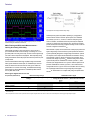
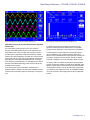
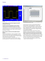
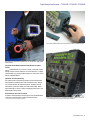
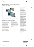
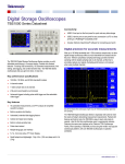
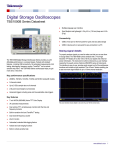
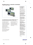
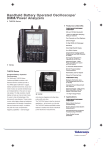
Digital Storage Oscilloscopes
TPS2012B • TPS2014B • TPS2024B Datasheet
Traditional, Analog-style Knobs and Multilanguage User Interface for
Easy Operation
Quick Setup and Operation with Autoset Menu, Autorange, Waveform
and Setup Memories, and Built-in, Context-sensitive Help
Backlit Menu Buttons for High Visibility
11 of the Most Critical Automatic Waveform Measurements
Applications
Industrial Power Design, Troubleshooting, Installation, and Maintenance
Features & Benefits
Advanced Electronics Design, Troubleshooting, Installation, and
Maintenance
100 MHz and 200 MHz Bandwidths
Automotive Design and Test
Sample Rates up to 2 GS/s Real Time
Education
2 or 4 Fully Isolated and Floating Channels, plus Isolated External
Trigger
8 Hours of Continuous Battery Operation with Two Batteries Installed,
Hot Swappable for Virtually Unlimited Freedom from AC Line Power
Optional Power Application Software offers the Broadest Range of
Power Measurements at its Price Point
Quickly Document and Analyze Measurement Results with
OpenChoice® Software or Integrated CompactFlash® Mass Storage
FFT Standard on All Models
Advanced Triggers to Quickly Capture the Event of Interest
TPS2000B Series Oscilloscopes for Powerful
Productivity from Bench to Field
The TPS2000B Series offers a distinctive range of capabilities in an
oscilloscope with controls and menus you will find familiar and easy to
use. Available in 2- or 4-channel versions, the TPS2000B Series with
IsolatedChannel™ technology provides isolation from ground and isolation
between channels allowing you to take measurements with less worry
about damaging circuitry. Battery power comes standard, making it a
natural choice for field applications. For work on power electronics, optional
software integrates commonly needed power system measurements into
the instrument, speeding up power analysis and troubleshooting.
Datasheet
Input signal and float voltage maximum safety ratings.
Four IsolatedChannel™ inputs and isolated external trigger input for quick, accurate,
affordable floating and differential measurements.
Make Floating and Differential Measurements –
Quickly, Accurately, Affordably
Unintentionally grounding a circuit under test is a common cause of
poor measurement results and circuit damage. Connecting two or more
grounded probes can cause ground loops, and if the current is high enough
can result in ruined components and equipment. Most importantly, taking
floating measurements without the proper instruments and probes can pose
a safety hazard.
Tektronix IsolatedChannel technology simplifies floating measurements.
Unlike ground-referenced oscilloscopes, the TPS2000B input connector
shells are isolated from each other and from earth ground. Within the
specified 600 VRMS maximum float voltage, IsolatedChannel technology
keeps current from flowing between the TPS2000B input BNC shells or
from any BNC shell to earth.
Different passive probes are available, depending on your application.
With the included TPP0101/TPP0201 passive probes, the TPS2000B
can measure up to 400 Vp-p. However, to meet the safety rating of the
TPP0101/TPP0201, the reference lead of the probe must be maintained
within 30 VRMS relative to ground. Because of this, the TPP0101/TPP0201
probes are well suited for working on digital and analog circuits in which the
maximum voltage never exceeds 30 VRMS.
Measurements on power conversion electronics usually require probes with
higher voltage ratings. Tektronix offers two passive probes with insulation
systems specifically designed for making floating measurements. Optional
P5122 probes, when coupled with the TPS2000B, are suitable for making
measurements on 480 VRMS devices in Category II environments, with a
maximum float voltage of up to 600 VRMS relative to earth ground. With the
optional P5120 probe the TPS2000B can measure up to 800 Vp-p, with a
maximum float voltage within 600 VRMS of ground. With the optional P5120
probe the TPS2000B can measure up to 800 Vp-p with a maximum float
voltage within 600 VRMS of ground. The P5120 is the best choice for making
AC-coupled ripple measurements on high-voltage DC power supplies.
Please see “Characteristics” for complete safety ratings and specifications.
Selecting the Right Probes for the Job
Scope/Probe (Attenuation)
TPS2000B Input (1X)
TPP0101 (100 MHz)
TPP0201 (200 MHz)
P5120 (20X)
P5122*2 (100X)
Maximum Safety Ratings
TPS2000B Viewable Signal
Reference Float Safety
Rating*1
Input Signal Safety Rating
On-screen Peak-Peak
Voltage (Sinusoid centered
at 0 V)
On-screen RMS Voltage
(Sinusoid centered at 0 V)
600 VRMS CAT II
30 VRMS
300 VRMS CAT II
300 VRMS CAT II
40 Vp-p
400 Vp-p
14.1 VRMS
141 VRMS
600 VRMS CAT II
600 VRMS CAT II
1000 VRMS CAT II
1000 VRMS CAT II
800 Vp-p
2828 Vp-p
282 VRMS
1000 VRMS
*1 Passive probe reference leads have no attenuation so any working voltage or over-voltage transients pass straight through to the scope reference. Thus, a passive probe reference float rating can never exceed the scope
reference float rating.
*2 The P5122 probe should not be used for AC-coupled measurements on signals with greater than 300 V DC offset. The P5120 is the recommended probe for measuring ripple on high-voltage DC supplies.
2
www.tektronix.com
Digital Storage Oscilloscopes — TPS2012B • TPS2014B • TPS2024B
Perform three-phase power measurements of variable frequency drives.
Speed the Design and Test of Industrial Power Systems
and Circuits
From mobile phones to industrial motor drives, power conversion
technology has enabled significant advances in size, performance, and
energy efficiency. But even the most basic task of viewing a converter’s
input and output is complicated by multiple voltage references. Multiple
references also make it challenging to view signals from control circuits and
power circuits at the same time. Using ground-referenced oscilloscopes in
these applications, without appropriate differential probes, can damage
circuits and produce bad measurements. For debugging power conversion
electronics, IsolatedChannel technology reduces the risk of damage and
unintended circuit interactions.
For performing power system measurements, TPS2PWR1 power
application software is available as an option for the TPS2000B. It provides
advanced power measurements right on the oscilloscope, at an entry-level
price.
Conduct harmonic distortion measurements with TPS2PWR1 software.
For dialing in the performance of switching components, the power
application software adds important measurements to the TPS2000B,
including automatic switching loss, dv/dt, and di/dt cursor measurements.
For measurements on AC line voltage and for checking the impact on
the power distribution system, the power application software shows
harmonic content to the 50th harmonic, and provides phase, reactive power
consumption, and power factor measurements. With the four-channel
TPS2014B or TPS2024B, you can view three-phase voltages or currents.
Two power “bundles” are available, combining probes and measurement
software. Each package combines four probes with the TPS2PWR1 power
application software, at prices that are lower than if purchased separately.
The TPS2PBND combines four P5120 20X passive, high-voltage probes
with TPS2PWR1 power application software. The TPS2PBND2 combines
four P5122 100X passive, high-voltage probes with the power application
software.
www.tektronix.com
3
Datasheet
Capture elusive glitches – the first time – with Digital Real-Time (DRT) sampling
technology.
Quickly Debug and Characterize Signals with DRT
Sampling Technology
Characterize a wide range of signal types on up to four channels
simultaneously with the TPS2000B Series Digital Real-Time (DRT)
sampling technology. This acquisition technology makes it possible to
capture high-frequency events, such as glitches and edge anomalies, that
eludes other oscilloscopes in its class, so that you can be sure to get an
accurate view of your signal.
Easily Analyze and Document Your Measurement
Results
Quickly reveal signal interference, crosstalk, and the effects of vibration
with frequency domain analysis using the TPS2000B Series Fast Fourier
Transform (FFT) feature. Then, easily document your measurement results
with the integrated CompactFlash® mass storage.
To capture, save, and analyze your measurement results on your PC,
the included OpenChoice® PC software can be used. Every TPS2000B
4
www.tektronix.com
Speed documentation and analysis of measurements results with OpenChoice® software
and integrated CompactFlash® mass storage.
Series also ships with a free copy of the special Tektronix Edition of
National Instrument’s LabVIEW SignalExpress™ software for basic
instrument control, data logging, and analysis. The optional Professional
Edition of SignalExpress offers over 200 built-in functions that provide
additional signal processing, advanced analysis, sweeping, limit testing,
and user-defined step capabilities.
SignalExpress supports the range of Tektronix bench instruments*3,
enabling you to connect your entire test bench. You can then access the
feature-rich tools packed into each instrument from one intuitive software
interface. This allows you to automate complex measurements requiring
multiple instruments, log data for an extended period of time, time-correlate
data from multiple instruments, and easily capture and analyze your results,
all from your PC. Only Tektronix offers a connected test bench of intelligent
instruments to simplify and speed debug of your complex design.
*3 To see the full range of Tektronix instruments supported by the Tektronix Edition of NI LabVIEW
SignalExpress, visit www.tektronix.com/signalexpress.
Digital Storage Oscilloscopes — TPS2012B • TPS2014B • TPS2024B
Enjoy virtually unlimited freedom from an AC power source with hot-swappable batteries.
Easily correlate your measurements between bench, lab, and field with the highly portable
TPS2000B Series.
Correlate Your Measurements from Bench to Lab to
Field*4
Use the TPS2000B Series on your bench, in the lab, or in the field, with the
industry’s longest continuous battery life – 8 hours and beyond – in a highly
mobile package. Enjoy virtually unlimited freedom from an AC power source
with hot-swappable batteries.
Optimize Your Productivity
The oscilloscope has a front-panel layout that most users will find familiar.
Each channel has a dedicated set of scale and position controls. Reduce
your measurement time with features like autoset, autorange, automatic
measurements, probe check wizard, and context-sensitive help. Backlit
menu buttons help you work in a variety of challenging environments – from
bright daylight to dimly lit areas.
Performance You Can Count On
In addition to industry-leading service and support, every TPS2000B Series
oscilloscope comes backed with a three-year standard warranty.
*4 Please refer to Environmental and Safety specifications.
Easily use the oscilloscope even in environments that challenge operation, with features
such as analog-style knobs per channel and backlit menu buttons.
www.tektronix.com
5
Datasheet
Characteristics
TPS2000B Series Electrical Characteristics
Feature
Isolated Channels
Bandwidth*5 (MHz)
Sample Rate (GS/s) per Channel
Record Length
Display (1/4 VGA LCD)
Battery Operation
Automatic Measurements
Isolated External Trigger Input (Impedance
isolated)
Vertical Resolution
Vertical Sensitivity
DC Vertical Accuracy
Vertical Zoom
Max Input Voltage (1 MΩ)
Float Voltage
Position Range
Bandwidth Limit
Linear Dynamic Range
Time Base Range
Time Base Accuracy
Input Impedance
Input Coupling
Horizontal Zoom
FFT
RS-232, Centronics-Parallel Ports
PC Connectivity
Integrated CompactFlash® Mass Storage
Power Measurements
TPS2012B
2
100
1.0
TPS2014B
TPS2024B
4
100
1.0
2.5k points
Color
Capacity for two hot-swappable battery packs
One standard battery pack offers 4 hours of battery operation
Optional second battery pack extends battery operation to 8 hours
Continuous battery operation is possible by hot-swapping charged batteries
11
Yes
4
200
2.0
8 bits (normal or with averaging)
2 mV to 5 V/div on all models with calibrated fine adjustment
±3%
Vertically expand or compress a live or stopped waveform
300 VRMS CAT II from BNC signal to BNC shell
600 VRMS CAT II from BNC shell to earth ground
2 mV to 200 mV/div ±1.8 V
>200 mV to 5 V/div ±45 V
20 MHz
±5 div
5 ns to 50 s/div
5 ns to 50 s/div
2.5 ns to 50 s/div
50 ppm
1 MΩ ±2% in parallel with 20 pF
AC, DC, GND
Horizontally expand or compress a live or stopped waveform
Standard
Standard
Standard
Standard
Optional package that offers instantaneous power waveform analysis, waveform analysis, harmonics
analysis, switching loss, phase angles, dv/dt and di/dt cursors
*5 Bandwidth is 20 MHz at 2 mV/div, all models. For TPS2024B, 200 MHz bandwidth is typical at 5 mV/div. Bandwidth is 200 MHz at 10 mV/div and above, for operating temperatures from 0 °C to 40 °C. Bandwidth is 180 MHz for all
V/div settings 10 mV/div and above, for operating temperatures from 0 °C to 50 °C.
6
www.tektronix.com
Digital Storage Oscilloscopes — TPS2012B • TPS2014B • TPS2024B
Acquisition Modes
Measurement System
Mode
Description
Characteristic
Description
Peak Detect
High-frequency and random glitch capture. Captures
glitches as narrow as 12 ns typical using acquisition
hardware at all time/div settings from 5 μs/div to 50 s/div
Sample data only
Waveform averaged, selectable: 4, 16, 64, 128
Use the Single Sequence button to capture a single
triggered acquisition sequence at a time
At acquisition time-base settings of ≥100 ms/div
Automatic Waveform
Measurements
Period, Frequency, +Width, –Width, Rise Time, Fall Time,
Max, Min, Peak-to-Peak, Mean, Cycle RMS
Sample
Average
Single Sequence
Scan/Roll Mode
Trigger System (Main Only)
Characteristic
Description
Trigger Modes
Auto, Normal, Single Sequence
Characteristic
Description
Operators
FFT
Add, Subtract, Multiply, FFT
Windows: Hanning, Flat Top, Rectangular; 2048 sample
points
Sources
2-channel Models
4-channel Models
Autoset Menu
Autorange
Trigger Types
Trigger
Waveform Processing
CH1 – CH2, CH2 – CH1, CH1 + CH2, CH1 × CH2
CH1 – CH2, CH2 – CH1, CH3 – CH4, CH4 – CH3, CH1 +
CH2, CH3 + CH4, CH1 × CH2, CH3 × CH4
Single-button, automatic setup of all channels for vertical,
horizontal, and trigger systems, with undo autoset
Allows the user to change test points without resetting the
oscilloscope
Description
Edge (Rising or falling) Conventional level-driven trigger. Positive or negative
slope on any input.
Coupling Selections: AC, DC, Noise Reject, HF Reject,
LF Reject
Video
Trigger on all lines or individual line, odd/even or all fields
from composite video, or broadcast standards (NTSC,
PAL, SECAM)
Pulse Width (or glitch) Trigger on a pulse width less than, greater than, equal
to, or not equal to a selectable time limit ranging from
33 ns to 10 s
Trigger Source
Characteristic
Description
2-channel Models
4-channel Models
CH1, CH2, Ext, Ext/5, Ext/10
CH1, CH2, CH3, CH4, Ext, Ext/5, Ext/10
Trigger View
Displays trigger signal while trigger view button is depressed.
Trigger Signal Frequency Readout
Provides a frequency readout of the trigger source with 6-digit resolution.
Cursors
Characteristic
Description
Types
Measurements
Voltage, Time
ΔT, 1/ΔT (frequency), ΔV, dv/dt*6, di/dt*6
Autoset Menu for Multiple Signal Types
Signal Type
Autoset Menu Choices
Square Wave
Sine Wave
Video (NTSC, PAL,
SECAM)
Single Cycle, Multicycle, Rising or Falling Edge
Single Cycle, Multicycle, FFT Spectrum
Video (NTSC, PAL, SECAM)
Field:
All, Odd, or Even Line: All or Selectable Line Number
Nonvolatile Storage
Characteristic
Description
Nonvolatile Storage
Reference Waveform
Display
Waveform Storage
Setups
Screen Images
CompactFlash® up to 2 GB
Two 2500 point reference waveforms
Save All
96 or more reference waveforms per 8 MB
4000 or more front-panel setups per 8 MB
128 or more screen images per 8 MB (the number of
images depends on file format selected)
12 or more Save All operations per 8 MB. A single Save
All operation creates 2 to 9 files (setup, image, plus one
file for each displayed waveform)
Display Characteristics
Characteristic
Description
Display
Interpolation
Display Types
Persistence
Format
1/4 VGA Active TFT Color LCD display
Sin (x)/x
Dots, vectors
Off, 1 sec, 2 sec, 5 sec, Infinite
YT and XY
www.tektronix.com
7
Datasheet
CAT Ratings
I/O Interface
Characteristic
Description
RS-232 Port (Standard)
RS-232
Programmability
Mass Storage
CompactFlash®
Memory
9-pin DTE
Full talk/listen modes. Control of all modes, settings, and
measurements. Baud rate up to 19,200
Accepts any Type 1 CompactFlash® card, up to and
including 2 GB (card not included)
Overvoltage Categories
Category
Examples of Products in this Category
CAT III
CAT II
CAT I
Distribution-level mains, fixed installation
Local-level mains, appliances, portable equipment
Signal levels in special equipment or parts of equipment,
telecommunications, electronics
Built-in Clock/Calendar
Seamless connection from oscilloscope to PC through
RS-232.
Transfer and save settings, waveforms, measurements,
and screen images.
Includes a Windows desktop data transfer application in
addition to convenient Microsoft Word and Excel toolbar
add-ins
Printer Port (Standard) Centronics-type Parallel
Graphics File
TIFF, PCX (PC Paint Brush), BMP (Microsoft Windows),
Formats
EPS (Encapsulated Postscript), and RLE
Printer Formats
Bubble Jet, DPU-411, DPU-412, DPU-3445, Thinkjet,
Deskjet, Laser Jet, Epson Dot (9- or 24-pin), Epson C60,
Epson C80
Layout
Landscape and Portrait
OpenChoice PC
Communications
Software
*6 Requires TPS2PWR1 power application package.
Environmental and Safety
Characteristic
Temperature
Operating
Nonoperating
Humidity
Operating
Nonoperating
Altitude
Operating
Nonoperating
Pollution Degree 2
Enclosure Rating
IP30
Electromagnetic
Compatibility
Safety
8
Description
0 °C to +50 °C
–40 °C to +71 °C
TPS2000B Series oscilloscopes are not intended for use
in wet or damp conditions
High: 50 °C / 60% RH
Low: 30 °C / 90% RH
High: 55 °C to 71 °C / 60% RH max wet bulb
Low: 30 °C to 0 °C / <90% RH max wet bulb
Up to 3,000 m
15,000 m
Do not operate in an environment where
conductive pollutants may be present (as defined
in IEC61010-1:2001)
When the CompactFlash® card and power analysis
software are installed (as defined in IEC60529:2001)
Meets the intent of Directive 89/336/EEC.
Meets or Exceeds: Australian EMC Framework,
demonstrated per Emission Standard AS/NZS 2064.1/2
UL61010-1: 2004. CAN/CSA22.2 No. 1010.1: 2004.
EN61010-1: 2001.
Do not float the TPP0101/TPP0201 probe common lead
to >30 VRMS. Use the P5122, P5120 (floatable to 600 VRMS
CAT II) or similarly rated passive, high-voltage probe, or
an appropriately rated high-voltage, differential probe
when floating the common lead above 30 VRMS
www.tektronix.com
Materials – TPSBAT battery contains less than 8 grams equivalent Lithium.
Physical Characteristics
INSTRUMENT
Dimensions
mm
in.
Width
Height
Depth
336.0
161.0
130.0
13.24
6.33
5.10
Weight
kg
lb.
Instrument Only
with 1 battery
with 2 batteries
2.7
3.2
3.7
6.0
7.0
8.0
INSTRUMENT SHIPPING
Package Dimensions
mm
in.
Width
Height
Depth
476.2
266.7
228.6
18.75
10.50
9.00
Digital Storage Oscilloscopes — TPS2012B • TPS2014B • TPS2024B
Ordering Information
Recommended Probes
TPS2012B, TPS2014B, TPS2024B
Accessory
Description
A621
A622
P5122*2
P5205
2000 A, 5-50 kHz AC current probe/BNC
100 A, 100 kHz AC/DC current probe/BNC
200 MHz passive 100X high-voltage probe
High-voltage active differential probe (1300 Vp-p, 100 MHz)
(1103 power supply required)
High-voltage active differential probe (5600 Vp-p, 50 MHz)
(1103 power supply required)
2.5 A, 200 MHz AC current probe
15 A, 50 MHz AC/DC current probe (1103 power supply
required)
150 A, 15 MHz AC/DC current probe/amplifier
50 A, 50 MHz AC/DC current probe/amplifier
30 A, 100 MHz, DC/AC current probe/amplifier
500 A, 2 MHz AC/DC current probe/amplifier
Digital Storage Oscilloscopes.
Standard Accessories
Accessory
Description
Probes
TPP0101 100 MHz, 10X passive probe for TPS2012B and
TPS2014B; TPP0201 200 MHz, 10X passive probe for
TPS2024B; one probe per channel standard
Battery (1)
Lithium-ion battery with fuel gauge for 4-hour battery life.
Two batteries required for 8 hours of continuous battery
operation
USB to RS-232 Cable A cable to connect to a PC USB port through the RS-232
port on the backside of the scope
OpenChoice® PC
A collection of programs that enable fast and easy
Connectivity Software communication between MS Windows PCs and
TPS2000B Series oscilloscopes
NI SignalExpress™ Tek A program that enables easy communication between
PC-based NI SignalExpress software and TPS2000B
Edition Software
Series oscilloscopes
Documentation
User Manual (please see below for available language
options)
AC Adapter with Power
Cord
NIM/NIST-Traceable
Certificate of
Calibration
Front Protective Cover
Recommended Accessories
Accessory
Description
TPS2PBND2
Power bundle for TPS2000B oscilloscopes. Includes
(4) P5122 passive, 100X high-voltage probes and
TPS2PWR1 power measurement and analysis software
Power measurements application package.
Instantaneous power waveform analysis, waveform
analysis, harmonics analysis, switching loss, phase
angles, dv/dt and di/dt cursors
WaveStar software; Microsoft Windows application
for waveform capture, analysis, documentation, and
control from your PC. Provides enhanced oscilloscope
data measurement, analysis, remote setup and charting
features
Additional battery
Battery charger
Soft case for carrying instrument
Hard case for carrying instrument (requires AC2100)
Service Manual – English only
Programmer Manual – English only
TPS2PWR1
WSTRO
TPSBAT
TPSCHG
AC2100
HCTEK4321
077-0447-xx
077-0444-xx
P5210
CT2
TCP202
TCP303/TCPA300
TCP305/TCPA300
TCP312/TCPA300
TCP404XL/TCPA400
*2 The P5122 probe should not be used for AC-coupled measurements on signals with greater than 300 V DC
offset. The P5120 is the recommended probe for measuring ripple on high-voltage DC supplies.
International Power Plugs
Option
Description
Opt.
Opt.
Opt.
Opt.
Opt.
Opt.
Opt.
Opt.
Opt.
Opt.
North America power
Universal Euro power
United Kingdom power
Australia power
Switzerland power
Japan power
China power
India power
Brazil power
No power cord or AC adapter
A0
A1
A2
A3
A5
A6
A10
A11
A12
A99
Accessory Cables
Cable
Description
012-1241-xx
RS-232, 9-Pin Female to 25-Pin Male, 4.6 m (15 ft.), for
modems
RS-232, 9-Pin Female to 9-Pin Female, null modem, for
computers
RS-232, 9-Pin Female to 25-Pin Female, null modem, for
computers
Centronics, 25-Pin Male to 36-Pin Centronics,
2.4 m (8 ft.), for parallel printer interfaces
012-1651-xx
012-1380-xx
012-1214-xx
International User Manual Language Options
Translated front-panel overlay included with its respective user manual.
Option
Description
Opt.
Opt.
Opt.
Opt.
Opt.
Opt.
Opt.
Opt.
Opt.
Opt.
Opt.
English (071-1441-xx)
French (071-1442-xx)
Italian (071-1443-xx)
German (071-1444-xx)
Spanish (071-1445-xx)
Japanese (071-1446-xx)
Portuguese (071-1447-xx)
Simplified Chinese (071-1448-xx)
Traditional Chinese (071-1449-xx)
Korean (071-1450-xx)
Russian (071-1451-xx)
L0
L1
L2
L3
L4
L5
L6
L7
L8
L9
L10
www.tektronix.com
9
Datasheet
Service Options
Option
Description
Opt. SILV200
Standard Warranty Extended to 5 Years
Warranty Information
Tektronix Support Completes the Solution
Anytime you need support, anywhere in the world, depend on Tektronix Support
to give you the lowest possible exposure to inconvenience, delay, or disruption of
operations. www.tektronix.com/support
Three-year warranty covering all labor and parts, excluding probes and accessories.
Unsurpassed technical expertise and experience with 24-hour response
to technical questions
Speed Product Development with Best-in-Class
Price/Performance
Industry-leading turnaround service time
The extensive Tektronix portfolio of proven, state-of-the-art stimulus, probing,
acquisition, and analysis tools simplify and speed each phase of product design –
from power-on and verification, through debug and validation, to characterization
and test – to enable you to race products to your customers when they need them,
if not before.
10
www.tektronix.com
90-day unconditional service warranty
No fine print, no exclusions, no surprises
Global support in more than 50 countries
Digital Storage Oscilloscopes — TPS2012B • TPS2014B • TPS2024B
www.tektronix.com
11
Datasheet
Contact Tektronix:
ASEAN / Australasia (65) 6356 3900
Austria 00800 2255 4835*
Balkans, Israel, South Africa and other ISE Countries +41 52 675 3777
Belgium 00800 2255 4835*
Brazil +55 (11) 3759 7627
Canada 1 800 833 9200
Central East Europe and the Baltics +41 52 675 3777
Central Europe & Greece +41 52 675 3777
Denmark +45 80 88 1401
Finland +41 52 675 3777
France 00800 2255 4835*
Germany 00800 2255 4835*
Hong Kong 400 820 5835
India 000 800 650 1835
Italy 00800 2255 4835*
Japan 81 (3) 6714 3010
Luxembourg +41 52 675 3777
Mexico, Central/South America & Caribbean 52 (55) 56 04 50 90
Middle East, Asia, and North Africa +41 52 675 3777
The Netherlands 00800 2255 4835*
Norway 800 16098
People’s Republic of China 400 820 5835
Poland +41 52 675 3777
Portugal 80 08 12370
Republic of Korea 001 800 8255 2835
Russia & CIS +7 (495) 7484900
South Africa +41 52 675 3777
Spain 00800 2255 4835*
Sweden 00800 2255 4835*
Switzerland 00800 2255 4835*
Taiwan 886 (2) 2722 9622
United Kingdom & Ireland 00800 2255 4835*
USA 1 800 833 9200
* European toll-free number. If not accessible, call: +41 52 675 3777
Updated 10 February 2011
For Further Information. Tektronix maintains a comprehensive, constantly expanding
collection of application notes, technical briefs and other resources to help engineers working
on the cutting edge of technology. Please visit www.tektronix.com
Copyright © Tektronix, Inc. All rights reserved. Tektronix products are covered by U.S. and foreign patents,
issued and pending. Information in this publication supersedes that in all previously published material.
Specification and price change privileges reserved. TEKTRONIX and TEK are registered trademarks of
Tektronix, Inc. All other trade names referenced are the service marks, trademarks, or registered trademarks
of their respective companies.
25 Jul 2012
www.tektronix.com
3MW-17750-10