1
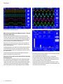
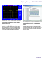
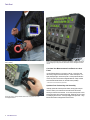
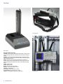
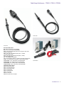
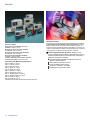
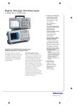
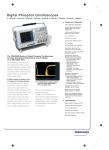
Digital Storage Oscilloscopes
TPS2012 • TPS2014 • TPS2024 Data Sheet
Easily Operate the Oscilloscope with Traditional, Analog-style Knobs
and Multilanguage User Interface
Simplify Setup and Operation with Autoset Menu, Autorange, Waveform
and Setup Memories, and Built-in, Context-sensitive Help
Adjust the Oscilloscope to Your Operating Environment with Backlit
Menu Buttons/Display and Brightness/Contrast Controls
11 Automatic Measurements
Applications
Industrial Power Design, Troubleshooting, Installation, and Maintenance
Advanced Electronics Design, Troubleshooting, Installation, and
Maintenance
Automotive Design and Test
Features & Benefits
100 MHz and 200 MHz Bandwidths
Sample Rates up to 2 GS/s Real Time
2 or 4 Fully Isolated and Floating Channels, plus Isolated External
Trigger
8 Hours of Continuous Battery Operation with Two Batteries Installed,
Hot-swappable for Virtually Unlimited Freedom from an AC Power
Source
Optional Power Application Software Offers the Broadest Range of
Power Measurements at its Price Point
Quickly Document and Analyze Measurement Results with
OpenChoice® Software or Integrated CompactFlash® Mass Storage
FFT Standard on all Models
Advanced Triggers to Quickly Capture the Event of Interest
Education
TPS2000 Series Oscilloscopes Deliver
Powerful Productivity from Bench to Field
As an engineer or technician, you must often make floating, or differential,
measurements. You face faster edges and clocks due to the migration of
higher performance technologies to widely implemented electronic systems
and subsystems, with the pressure to conform to customer specifications or
industry requirements.
And you may need to develop and test designs in a variety of challenging
environments that demand versatility.
You can quickly tackle these tough challenges to speed the design,
troubleshooting, installation, and maintenance of components and systems
with the world’s first 4-isolated-channel, full featured, battery-powered
oscilloscope – the TPS2000 Series.
Data Sheet
Four IsolatedChannel™ inputs and isolated external trigger input for quick, accurate,
affordable floating and differential measurements.
Perform three-phase power measurements of variable frequency drives.
Make Floating and Differential Measurements – Quickly,
Accurately, Affordably
Make floating and differential measurements much more quickly and
accurately, and speed verification of power supply performance, complex
control circuits, and the effects of neutral current for differential voltages, up
to 30 VRMS floating on four channels simultaneously, when the TPS2000
Series is paired with its standard P2220 passive probe.
Easily perform these measurements up to 600 VRMS CAT II (or 300 VRMS
CAT III) floating when the oscilloscope is coupled with its optional P5120
passive, high-voltage probe.
Accurately characterize rise and fall times and other waveform parameters
in circuits with different low levels or ground references, while removing
ground loop interference, with just 37 pf capacitance to chassis on each of
four isolated channels.
Innovative IsolatedChannel™ technology makes these measurements
possible - all designed with your safety in mind.
Speed the Design and Test of Industrial Power Systems
and Subsystems
The TPS2000 Series easily addresses the unique challenges that plague
industrial power designers and technicians. You regularly confront high
voltages and currents, and must often make potentially hazardous floating
measurements. With the TPS2000 Series’ power bundle (TPS2PBND),
which includes the P5120 passive, high-voltage probes and TPS2PWR1
2
www.tektronix.com
Conduct harmonic distortion measurements with TPS2PWR1 software.
power measurement and analysis software, you can use a single instrument
to make a broad range of measurements.
Easily evaluate these high voltages and currents, or debug power
electronics control circuits, with differential voltages up to 600 VRMS CAT II
(or 300 VRMS CAT III) floating. Accurately measure three-phase power and
circuits with different low levels or ground references.
Quickly perform a broad range of power-specific measurements, such as
switching loss, harmonic distortion measurements to the 50th harmonic, and
dv/dt and di/dt cursor measurements.
Digital Storage Oscilloscopes — TPS2012 • TPS2014 • TPS2024
Capture elusive glitches - the first time - with digital real-time (DRT) sampling technology.
Quickly Debug and Characterize Signals with DRT
Sampling Technology
Characterize a wide range of signal types on four channels simultaneously
with the TPS2000 Series’ unique digital real-time (DRT) sampling
technology. This acquisition technology makes it possible to capture
high-frequency information, such as glitches and edge anomalies, that
eludes other oscilloscopes in its class, so that you can be sure to get a
complete view of your signal to speed debug and characterization.
Speed documentation and analysis of measurements results with OpenChoice® software
and integrated CompactFlash® mass storage.
Easily Analyze and Document Your Measurement
Results
Quickly reveal signal interference, crosstalk and the effects of vibration
with frequency domain analysis using the TPS2000 Series’ standard
Fast Fourier Transform (FFT) feature. Easily analyze and document your
measurement results with integrated CompactFlash® mass storage or
OpenChoice® software.
www.tektronix.com
3
Data Sheet
Easily correlate your measurements between bench, lab, and field with the TPS2000
Series’ portability.
Easily use the oscilloscope even in environments that challenge operation, with features
such as analog-style knobs per channel, backlit menu buttons, and brightness/contrast
controls.
Correlate Your Measurements from Bench to Lab to
Field*1
Use the TPS2000 Series on your bench, in the lab, or in the field, with
the industry’s longest continuous battery life – 8 hours and beyond – in a
highly mobile package. Harness the power of virtually unlimited freedom
from an AC power source with hot-swappable batteries. Easily correlate
measurements between bench, lab, and field with its portability.
*1 Please refer to Environmental and Safety specifications.
Optimize Your Productivity with Versatility
Harness the power of virtually unlimited freedom from an AC power source with
hot-swappable batteries.
4
www.tektronix.com
Intuitively operate the oscilloscope with familiar, analog-style knobs per
channel. Reduce your measurement time with features like autoset,
autorange, automatic measurements, 10x to 1000x vertical position control,
probe check wizard, and context-sensitive help. Effectively work in a variety
of challenging environments – from bright daylight to dimly lit areas – using
backlit menu buttons and brightness/contrast controls.
Digital Storage Oscilloscopes — TPS2012 • TPS2014 • TPS2024
Characteristics
TPS2000 Series Electrical Characteristics
Feature
Isolated Channels
Bandwidth*2 (MHz)
Sample Rate (GS/s) per Channel
Record Length
Display (1/4 VGA LCD)
Battery Operation
Automatic Measurements
Isolated External Trigger Input (Impedance
isolated)
Vertical Resolution
Vertical Sensitivity
DC Vertical Accuracy
Vertical Zoom
Max Input Voltage (1 MΩ)*1
Float Voltage*1
Position Range
Bandwidth Limit
Linear Dynamic Range
Time Base Range
Time Base Accuracy
Input Impedance
Input Coupling
Horizontal Zoom
FFT
RS-232, Centronics-Parallel Ports
PC Connectivity
Integrated CompactFlash® Mass Storage
Power Measurements
TPS2012
TPS2014
TPS2024
2
100
1.0
4
100
1.0
2.5 K points
Color
Capacity for two hot-swappable battery packs
One standard battery pack offers 4 hours of battery operation
Optional second battery pack extends battery operation to 8 hours
Continuous battery operation is possible by hot-swapping charged batteries
11
Yes
4
200
2.0
8 bits (normal or with averaging)
2 mV to 5 V/div on all models with calibrated fine adjustment
±3%
Vertically expand or compress a live or stopped waveform
300 VRMS CAT II at BNC signal to BNC shell, 1000 VRMS CAT II at probe tip to earth ground with
optional P5120 passive, high-voltage probe
600 VRMS CAT II or 300 VRMS CAT III BNC shell to earth ground, 1200 VRMS CAT II between any two channel commons
with each of the channel commons not being more than ±600 VRMS from earth ground
2 mV to 200 mV/div ±2 V
>200 mV to 5 V/div ±50 V
20 MHz
±5 div
5 ns to 50 s/div
5 ns to 50 s/div
2.5 ns to 50 s/div
50 ppm
1 MΩ ±2% in parallel with 20 pF
AC, DC, GND
Horizontally expand or compress a live or stopped waveform
Standard
Standard
Standard
Standard
Optional package that offers instantaneous power waveform analysis, waveform analysis, harmonics
analysis, switching loss, phase angles, dv/dt and di/dt cursors
*1 Please refer to Environmental and Safety specifications.
*2 Bandwidth is 20 MHz at 2 mV/div, all models. Bandwidth is 200 MHz typical at 5 mV/div, 200 MHz models only. Bandwidth is 200 MHz typical between 40 °C and 50 °C, 200 MHz models only.
Acquisition Modes
Peak Detect – High-frequency and random glitch capture. Captures glitches as
narrow as 12 ns typical using acquisition hardware at all time/div settings from
5 μs/div to 50 s/div.
Sample – Sample data only.
Average – Waveform averaged, selectable: 4, 16, 64, 128.
Single Sequence – Use the Single Sequence button to capture a single triggered
acquisition sequence at a time.
Scan/Roll Mode – At acquisition time base settings of ≥100 ms/div.
www.tektronix.com
5
Data Sheet
Trigger System (Main Only)
Nonvolatile Storage
Trigger Modes – Auto, Normal, Single Sequence.
Characteristic
Description
Nonvolatile Storage
Reference Waveform
Display
Waveform Storage
Setups
Screen Images
Standard (with CompactFlash® mass storage)
Two 2500 point reference waveforms
Trigger Types
Edge (rising or falling) – Conventional level-driven trigger. Positive or negative slope
on any input. Coupling selections: AC, DC, Noise Reject, HF Reject, LF Reject.
Video – Trigger on all lines or individual line, odd/even or all fields from composite
video, or broadcast standards (NTSC, PAL, SECAM).
Pulse Width (or glitch) – Trigger on a pulse width less than, greater than, equal to, or
not equal to a selectable time limit ranging from 33 ns to 10 s.
Trigger Source
2-channel Models – CH1, CH2, Ext, Ext/5, Ext/10.
4-channel Models – CH1, CH2, CH3, CH4, Ext, Ext/5, Ext/10.
Trigger View
Displays trigger signal while trigger view button is depressed.
Trigger Signal Frequency Readout
Provides a frequency readout of the trigger source with 6-digit resolution.
Cursors
Types – Voltage, Time.
Measurements – ΔT, 1/ΔT (frequency), ΔV, dv/dt*3, di/dt*3.
*3 Requires TPS2PWR1 power application package.
Measurement System
Automatic Waveform Measurements – Period, Frequency, +Width, -Width, Rise time,
Fall time, Max, Min, Peak-to-Peak, Mean, Cycle RMS.
Waveform Processing
Operators – Add, Subtract, Multiply, FFT.
FFT – Windows: Hanning, Flat Top, Rectangular; 2048 sample points.
Sources –
2-channel Models: CH1 - CH2, CH2 - CH1, CH1 + CH2, CH1 × CH2.
4-channel Models: CH1 - CH2, CH2 - CH1, CH3 - CH4, CH4 - CH3, CH1 + CH2,
CH3 + CH4, CH1 × CH2, CH3 × CH4.
Autoset Menu – Single-button, automatic setup of all channels for vertical, horizontal,
and trigger systems, with undo autoset.
Autorange – Allows the user to change test points without resetting the oscilloscope.
Autoset Menu for Multiple Signal Types
Signal Type
Autoset Menu Choices
Square wave
Sine Wave
Video (NTSC, PAL,
SECAM)
Single-cycle, Multicycle, Rising or Falling Edge
Single-cycle, Multicycle, FFT Spectrum
Video (NTSC, PAL, SECAM)
Field:
All, Odd, or Even Line: All or Selectable Line Number
6
www.tektronix.com
Save All
96 or more reference waveforms per 8 MB
4000 or more front-panel setups per 8 MB
128 or more screen images per 8 MB (the number of
images depends on file format selected)
12 or more Save All operations per 8 MB. A single Save
All operation creates 2 to 9 files (setup, image, plus one
file for each displayed waveform)
Display Characteristics
Display – 1/4 VGA, passive color LCD with color on black background with adjustable
multilevel contrast and brightness controls.
Interpolation – Sin(x)/x.
Display Types – Dots, vectors.
Persistence – Off, 1 sec, 2 sec, 5 sec, infinite.
Format – YT and XY.
I/O Interface
Printer Port (standard) – Centronics-type Parallel.
Graphics File Formats – TIFF, PCX (PC Paint Brush), BMP (Microsoft
Windows), EPS (Encapsulated Postscript), and RLE.
Printer Formats – Bubble Jet, DPU-411, DPU-412, DPU-3445, Thinkjet,
Deskjet, Laser Jet, Epson Dot (9- or 24-pin), Epson C60, Epson C80.
Layout – Landscape and Portrait.
RS-232 Port (standard) – 9-pin DTE.
RS-232 Programmability – Full talk/listen modes. Control of all modes, settings, and
measurements. Baud rate up to 19,200.
Mass Storage CompactFlash® Memory –
• Accepts any Type 1 CompactFlash® card, up to and including 1 GB (card not
included).
Built-in Clock/Calendar
OpenChoice PC Communications Software –
Seamless connection from oscilloscope to PC through RS-232.
Transfer and save settings, waveforms, measurements, and screen images.
Includes a Windows desktop data transfer application in addition to convenient
Microsoft Word and Excel Toolbar Add-ins.
Digital Storage Oscilloscopes — TPS2012 • TPS2014 • TPS2024
Environmental and Safety
Materials – TPSBAT battery contains less than 8 grams equivalent Lithium.
Temperature –
Operating: 0 °C to +50 °C.
Nonoperating: -40 °C to +71 °C.
Humidity – TPS2000 Series oscilloscopes are not intended for use in wet or damp
conditions.
Operating:
High: 50 °C / 60% RH.
Low: 30 °C / 90% RH.
Nonoperating:
High: 55 °C to 71 °C / 60% RH max wet bulb.
Low: 30 °C to 0 °C / < 90% RH max wet bulb.
Altitude –
Operating: Up to 3,000 m.
Nonoperating: 15,000 m.
Pollution Degree 2 – Do not operate in an environment where conductive pollutants
may be present (as defined in IEC61010-1:2001).
Enclosure Rating –
IP30: When the CompactFlash® card and power analysis software are installed
(as defined in IEC60529:2001).
Physical Characteristics
INSTRUMENT
Dimensions
mm
in.
Width
Height
Depth
336.0
161.0
130.0
13.24
6.33
5.10
Weight
kg
lb.
Instrument only
with 1 battery
with 2 batteries
2.7
3.2
3.7
6.0
7.0
8.0
INSTRUMENT SHIPPING
Package Dimensions
mm
in.
Width
Height
Depth
476.2
266.7
228.6
18.75
10.50
9.00
Electromagnetic Compatibility –
Meets the intent of Directive 89/336/EEC.
Meets or Exceeds: Australian EMC Framework, demonstrated per Emission
Standard AS/NZS 2064.1/2.
General Certifications – Russian GOST EMC regulations.
Safety – UL61010-1: 2004. CAN/CSA22.2 No. 1010.1: 2004. EN61010-1: 2001.
Do not float the P2220 probe common lead to >30 VRMS. Use the P5120 (floatable to
600 VRMS CAT II or 300 VRMS CAT III) or similarly rated passive, high-voltage probe or
an appropriately rated high-voltage, differential probe when floating the common lead
above 30 VRMS, subject to the ratings of such high-voltage probe.
CAT Ratings
Overvoltage Categories
Category
Examples of Products in this Category
CAT III
CAT II
CAT I
Distribution-level mains, fixed installation
Local-level mains, appliances, portable equipment
Signal levels in special equipment or parts of equipment,
telecommunications, electronics
Ordering Information
TPS2012, TPS2014, TPS2024
Digital Storage Oscilloscopes
Standard Accessories
Probes – P2220 200 MHz, 1x/10x switchable passive probe (one per channel).
Battery (1) – Lithium-ion battery with fuel gauge for 4-hour battery life. Two batteries
required for 8 hours continuous battery operation.
TDSPCS1 OpenChoice PC Connectivity Software – A collection of programs that
enable fast and easy communication between MS Windows PCs and TPS2000
Series oscilloscopes.
Documentation – 1-each set of instruction manuals (see below for the appropriate
language manual part number).
AC Adapter with Power Cord.
NIM/NIST-Traceable Certificate of Calibration.
Front Protective Cover.
www.tektronix.com
7
Data Sheet
Soft carrying case.
Battery/charger.
Recommended Accessories
TPS2PBND – Power bundle for TPS2000 Series oscilloscopes. Includes (4) P5120
passive, high-voltage probes and TPS2PWR1 power measurement and analysis
software.
TPS2PWR1 – Power measurements application package. Instantaneous power
waveform analysis, waveform analysis, harmonics analysis, switching loss, phase
angles, dv/dt and di/dt cursors.
WSTRO – WaveStar software; Windows 98/2000/ME/NT 4.0 application for
waveform capture, analysis, documentation, and control from your PC. Provides
enhanced oscilloscope data measurement, analysis, remote setup and charting
features.
TPSBAT – Additional battery.
TPSCHG – Battery charger.
AC2100 – Soft case for carrying instrument.
HCTEK321 – Hard case for carrying instrument.
343-1689-xx – Versatile hanger.
Service Manual – English only (P/N 071-1465-xx).
Programmer Manual – English only (P/N 071-1075-xx).
156-9413-xx – CompactFlash® memory card, 32 MB or more.
8
www.tektronix.com
Versatile hanger.
Digital Storage Oscilloscopes — TPS2012 • TPS2014 • TPS2024
P2220 Probe.
P5120 Probe.
Recommended Probes
A621 – 2000 A, 5-50 kHz AC current probe/BNC.
A622 – 100 A, 100 kHz AC/DC current probe/BNC.
P5120 – Passive high-voltage probe (1000 V CAT II tip to ground; 600 V CAT II
reference to earth ground).
P5205 – High-voltage active differential probe (1300 Vp-p, 100 MHz).
(1103 power supply required).
P5210 – High-voltage active differential probe (5600 Vp-p, 50 MHz).
(1103 power supply required).
CT2 – 2.5 A, 200 MHz AC current probe.
CT4 – AC current probe up to 2000 Ap-p. (TCP202 and 1103 power supply required).
TCP202 – 15 A, 50 MHz AC/DC current probe. (1103 power supply required).
TCP303/TCPA300 – 150 A, 15 MHz AC/DC current probe/amplifier.
TCP305/TCPA300 – 50 A, 50 MHz AC/DC current probe/amplifier.
TCP312/TCPA300 – 30 A, 100 MHz, DC/AC current probe/amplifier.
TCP404XL/TCPA400 – 500 A, 2 MHz AC/DC current probe/amplifier.
Current Probes.
International Power Plugs
Opt. A0 – North America power.
Opt. A1 – Universal EURO power.
Opt. A2 – United Kingdom power.
Opt. A3 – Australia power.
Opt. A5 – Switzerland power.
Opt. A6 – Japan power.
Opt. A10 – China power.
Opt. A99 – No power cord or AC adapter.
www.tektronix.com
9
Data Sheet
Accessory Cables
RS-232, 9-Pin Female to 25-Pin Male, 4.6 m (15 ft.),
for Modems – Order 012-1241-xx.
RS-232, 9-Pin Female to 9-Pin Female, Null Modem,
for Computers – Order 012-1651-xx.
RS-232, 9-Pin Female to 25-Pin Female, Null Modem,
for Computers – Order 012-1380-xx.
RS-232, 9-Pin Female to 25-Pin Male, Null Modem,
for Printers – Order 012-1298-xx.
Centronics, 25-Pin Male to 36-Pin Centronics, 2.4 m (8 ft.),
for Parallel Printer Interfaces – Order 012-1214-xx.
International User Manual Language Options
Opt. L0 – English (071-1441-xx).
Opt. L1 – French (071-1442-xx).
Opt. L2 – Italian (071-1443-xx).
Opt. L3 – German (071-1444-xx).
Opt. L4 – Spanish (071-1445-xx).
Opt. L5 – Japanese (071-1446-xx).
Opt. L6 – Portuguese (071-1447-xx).
Opt. L7 – Simplified Chinese (071-1448-xx).
Opt. L8 – Traditional Chinese (071-1449-xx).
Opt. L9 – Korean (071-1450-xx).
Opt. 10 – Russian (071-1451-xx)
Translated front-panel overlay included with its respective user manual.
10
www.tektronix.com
Warranty Information
Three-year warranty covering all labor and parts, excluding probes and accessories.
Speed Product Development with Best-in-Class Price/Performance. Tektronix’
extensive portfolio of proven, state-of-the-art stimulus, probing, acquisition, and
analysis tools simplify and speed each phase of product design - from power-on and
verification, through debug and validation, to characterization and test - to enable you
to race products to your customers when they need them, if not before.
Tektronix Support Completes the Solution. Anytime you need
support, anywhere in the world, depend on Tektronix Support to give you
the lowest possible exposure to inconvenience, delay, or disruption of
operations. www.tektronix.com/support
Unsurpassed technical expertise and experience with 24-hour
response to technical questions
Industry-leading, turnaround service time
90-day unconditional service warranty
No fine print, no exclusions, no surprises
Global support in more than 50 countries
Digital Storage Oscilloscopes — TPS2012 • TPS2014 • TPS2024
www.tektronix.com
11
Data Sheet
Contact Tektronix:
ASEAN / Australasia (65) 6356 3900
Austria +41 52 675 3777
Balkans, Israel, South Africa and other ISE Countries +41 52 675 3777
Belgium 07 81 60166
Brazil +55 (11) 40669400
Canada 1 (800) 661-5625
Central East Europe, Ukraine, and the Baltics +41 52 675 3777
Central Europe & Greece +41 52 675 3777
Denmark +45 80 88 1401
Finland +41 52 675 3777
France +33 (0) 1 69 86 81 81
Germany +49 (221) 94 77 400
Hong Kong (852) 2585-6688
India (91) 80-42922600
Italy +39 (02) 25086 1
Japan 81 (3) 6714-3010
Luxembourg +44 (0) 1344 392400
Mexico, Central/South America & Caribbean 52 (55) 54247900
Middle East, Asia, and North Africa +41 52 675 3777
The Netherlands 090 02 021797
Norway 800 16098
People’s Republic of China 86 (10) 6235 1230
Poland +41 52 675 3777
Portugal 80 08 12370
Republic of Korea 82 (2) 6917-5000
Russia & CIS +7 (495) 7484900
South Africa +27 11 206 8360
Spain (+34) 901 988 054
Sweden 020 08 80371
Switzerland +41 52 675 3777
Taiwan 886 (2) 2722-9622
United Kingdom & Ireland +44 (0) 1344 392400
USA 1 (800) 426-2200
For other areas contact Tektronix, Inc at: 1 (503) 627-7111
Updated 30 October 2008
For Further Information. Tektronix maintains a comprehensive, constantly expanding
collection of application notes, technical briefs and other resources to help engineers working
on the cutting edge of technology. Please visit www.tektronix.com
Copyright © Tektronix, Inc. All rights reserved. Tektronix products are covered by U.S. and foreign patents,
issued and pending. Information in this publication supersedes that in all previously published material.
Specification and price change privileges reserved. TEKTRONIX and TEK are registered trademarks of
Tektronix, Inc. All other trade names referenced are the service marks, trademarks, or registered trademarks
of their respective companies.
22 Jul 2009
www.tektronix.com
3MW-17750-4