1
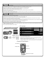
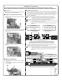
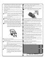
Instruction Manual for FI Controller
For Monkey (FI), Super Cub (FI), Little Cub (FI)
CO
Item No. 03−05−0013
Fits & Frame Nos
Monkey (FI) AB27-1900001〜
Super cub (FI) AA01-1700001〜
Little cub (FI) AA01-4000001〜
・Thank you for purchasing one of our TAKEGAWA’s products. You are requested to follow the below-mentioned instructions in installing this product.
・You are requested to follow the below-mentioned instructions in installing this kit. Should you have any questions about the products, please kindly contact
your local dealer.
◎ Please note that, in some cases, the illustrations and photos may vary from the actual hardware.
〜 Features 〜
○This is a subcomputer whose wires, supplied in this kit, can be connected to those of the genuine ECU just by cutting off the ECU’s wires. Thus, this kit is user-friendly
and can increase the amount of fuel injection.
○ If our S-Stage is incorporated into an FI motorcycle, the air-fuel ratio gets out of order on account of the increase in the engine displacement. But with the installation
of this kit, judging from the engine condition, a 16-bit microcomputer inside the FI controller computes in real time based on the signal sent from the genuine computer,
optimizing the air-fuel ratio by correcting the amount of fuel injection to meet our S-Stage.
○ The amount of increase of fuel injection can be adjusted in 15 steps with a rotary switch so that this kit can meet the changes in the intake and exhaust system.
○This kit makes possible the fuel injection in larger amount than the maximum amount to be injected by the genuine computer.
Please read the following instructions before installation.
PY
◎ We do not take any responsibility for any accident or damage whatsoever arising from the use of this product not in conformity with the instructions in this Manual.
◎ We shall be held free from any responsibility or compensation whatsoever for any glitch in the parts other than ours if the glitch takes place after the installation and
use of this product.
◎ You are kindly requested not to contact us about the combination of our products with other manufacturers’.
◎ Please note that this product is designed for exclusive use in the above-mentioned fitting models and that it cannot be mounted on any other models.
◎When ordering repair parts, please quote above Item No. or reference Nos in the figures in this Manual. Should you have any questions about the repair parts, please
contact your local motorcycle dealer.
◎ This product is designed to extend the fuel injection time through the incorporation of this product to the injection power from the genuine ECU.
◎ In the case of a technical trouble like the breakdown of this product or faulty wiring, it is structurally likely that the fuel injection may stop.
◎ There is no function to cancel the rotation limiter.
◎ The data, described in this Manual, on the increase in the fuel injection is based upon the test on the motorcycles owned by us and equipped with our products.
However, when this product is installed on altered motorcycles other than those motorcycles tested by us or on motorcycles using other manufacturers’ parts as well,
you may not be able to get the optimum settings for the air-fuel ratio.
◎However, even if your motorcycle is equipped with our products, in some cases, you cannot get the intended settings because of the individual part difference, or such
foreign elements as temperatures, height above sea level, or rider’s physical constitution.
◎ This product is a subcomputer which makes the general driving possible by increasing the amount of fuel injection in a simple way when our S-Stage is installed.
◎ Since this product is just a subcomputer, we do not warrant that this subcomputer always produces perfect settings with engines of any specifications. Moreover,
we shall not be liable for the breakdown of the engine.
◎ Before driving, be sure to always check whether the air-fuel ratio, or the setting, meets your engine.
◎ It is hoped that you will use this kit with all above in your mind.
Precautions in using this kit
◎ About those parts which cannot be used together with this kit.
Please never use any HID kits manufactured outside our factory, whose ballast and inverter (voltage converter) in most cases produce high-voltage
noise, giving adverse effect to the digital circuit and causing the breakdown of the FI controller.
Please never use such ignition devices as an ignition coil or a plug cord which are manufactured outside our factory, because the increase in radiation
noise caused by the increased ignition voltage may cause this product to malfunction or break down.
Please never use a generating equipment, manufactured outside our factory, which is likely to cause the breakdown of this product because of decrease
in voltage or unstable control voltage caused by the equipment's insufficient recharging capacity.
◎ This product is not structurally water- or drip-proof.
As this product is not structurally water- or drip-proof and if it gets wet with rain or water, the water may get inside the product, causing this product to
break down.
By the same token, please take precautions against water in washing your motorcycle. Immediately stop using the FI controller once water gets into it.
When the transparent panel is fit into the opening on the supplied switch and if it is humid or there is a sudden change in the temperatures, the transparent
panel may absorb moisture and get misted up in some cases.
◎ The body of this product is made of resin.
If you are going to keep a motorcycle outside for a long time, please put a cover on it to prevent this product from weathering. If this product is kept under
severe conditions like the scorching sun for a long period, there is a possibility that the resin or the rubber parts may deteriorate or deform.
◎ Never take this product apart.
Never disassemble or alter this product yourself, as it poses a danger to do so. And please be informed that in case you yourself have disassembled or
altered this product, we will not be in a position to comply with your request for the inspection or repair.
◎ Never make an impact on this product.
Please refrain from doing such things as off-road driving or jumping which may make a severe impact on this product.
Because of the impact, the inner parts may come off or the wires may be disconnected, possibly leading to the irreparable damage of the product or
breakage of the housing.
◎ About the maintenance.
In order to remove the greasy dirt, dissolve a small amount of mild detergent in water and rub the dirt slowly and carefully with the liquid.
Portions made of resin may deteriorate or a panel may mist up when they are rubbed with a volatile substance like thinner or alcohol, or with an abrasive compound.
‑1‑
Feb./18/ 09
CAUTION
The following show the envisioned possibility of injuries to human bodies or property damage as a result of disregarding the
following cautions.
・Always try to drive your motorcycle at legal speeds on the public road, abiding by the laws.
・Do the following work only when the engine and the muffler are cool. (Otherwise, you will burn yourself.)
・Prepare tools suitable for the work. (Otherwise, parts will be damaged or you will suffer injuries.)
・Always use a torque wrench to screw bolts and nuts tight and securely to the specified torque.
(Improper torque could cause these parts to get damaged or fall off.)
・As some products and frames have sharp-pointed or protruding portions, please work with your hands protected.
(Otherwise, you will suffer injuries.)
・Before riding, always check every hardware for slack in parts like screws. If you find slack ones, screw them securely up to the specified torque.
(Or, improper torque may cause parts to come off.)
CO
The following show the envisioned possibility of human death or serious injuries to human bodies as a result of disregarding the
WARNING following cautions.
・When you notice something unusual with your motorcycle while riding, stop riding immediately and park your motorcycle in a safe place.
(Otherwise, the continued ride could lead to accidents.)
・Before starting the work, secure your motorcycle firmly on level ground for safety’s sake.
(Otherwise, your motorcycle could overturn and injure you while you are working.)
・Please conduct checkups and maintenance correctly referring to the instructions and methods described in the instruction or service manual.
(Improper checkups and maintenance could lead to accidents.)
・If you find damaged parts when checking or performing maintenance of your motorcycle, do not use these parts any longer, and replace them with
new ones. (The continued use of these damaged parts as they are could lead to accidents.)
・Keep plastic bags for packing the products out of children’s reach, or discard them.
(If children get them on, there will be a danger of their suffocating.)
PY
◎ Please be informed that, mainly because of improvement in performance, design changes, or cost increase, the product specifications and prices are
subject to change without prior notice.
◎ This manual should be retained for future reference.
〜 Kit includes 〜
10
1、2
3
9
5
6
7
8
4
No.
1
2
3
4
5
6
7
8
9
10
Part Name
FI Controller Assembly
FI Controller panel (bored switch)
FI Controller panel (transparent switch)
Rubber cap
Plug
Plug receptacle
Plug cap(Plug cover)
Plug receptacle cap (Plug receptacle cover)
Velcro set
Insulation lock, 150 mm
Qty
1
1※
1
1
3
3
3
3
1
2
Repair Part Item No.
In packs of
38775-FC1-T00
1
91615-FC1-T00
1
00-00-0150
00-00-0135
1
10
※The FI Controller panel of Item No. 2 above with a bored switch is factory-installed onto
the FI Controller assembly of Item No.1.
Please note that in ordering repair parts, be sure to quote the Repair Part Item No.
Otherwise, we may not be able to accept your orders.
There are some parts, however, for which we are not in a position to accept your order
in just the quantity to be used. In this case, please take them in the quantity packed.
〜 Product & Parts Names 〜
FI controller
Red LED
Rotary switch
Green LED
Harness for FI controller
‑2‑
Feb./18/ 09
〜 Installation Procedures 〜
We have prepared this Instruction Manual on the assumption that our S-Stage had already been installed.
Please install this FI Controller in reference to this Instruction Manual but only after the installation of S-Stage Kit.
●Introduction:
Make sure your motorcycle is secure on a maintenance
stand or the like on level and safe ground.
CO
■Installation onto Cub (FI) and Little Cub (FI)
1.Referring to the genuine service manual, remove the
right side cover.
●Installation of FI Controller:
1.Cut off a total of 3 pieces of a pink / green, a black / blue and a green wires, at about
50 mm from the root of the coupler of the ECU. You may choose whichever green
wire out of three in the bundled green harness. Referring to the fig. below, attach and
process the supplied terminal, being careful of the kinds of the terminal, whether a
plug or a receptacle plug.
CAUTION : If you cut the harness too close to the ECU coupler, you will find it
impossible to install the terminal, because the plug receptacle cover is
long. Therefore, please be careful about where to cut the harness.
CAUTION : Install the terminal securely, using a proper tool like a plier.
CAUTION : In this Instruction Manual, the wire colors are shown in the order of whole
wire color and the line color on the wire.
The description of “pink / green” wire indicates a pink wire with a green
line on it.
! IMPORTANT !
Connect the plug receptacle to
the pink /green wire of the cutoff
harness on the vehicle side.
! IMPORTANT !
Connect the plug to the pink /
green wire of the cutoff harness
on the ECU side.
2.From the main harness, remove the coupler connected
to a genuine ECU. And unfasten the screw holding a
PY
On the side of the
vehicle harness
On the side of ECU
battery cover.
←About 50 mm→
ECU
P/G
P/G
B/L
B/L
G
G
※ The above wiring is based on our verification as of July 1, 2008.
3877 5-F C1-T00
MADE IN JAPAN
0123456789ABCDEF
SW. Pos.
POWER
.
D
ST
2.Referring to the illustration below, connect the terminal from the harness on the FI
controller to the terminal on the harness on the vehicle side.
CAUTION : Please note beforehand that, as a matter of convenience on our side, the
colors of the wires on the FI controller and those on the harness on the
vehicle differ. Therefore, please carefully connect wires with this in
mind.
.
E xt ct
je
In
e
T im
3.Disconnect the cable from the (-) terminal on the
battery.
ADD FUEL
! IMPORTANT !
Be sure to connect the plug of the
brown harness to the harness
side.
! IMPORTANT !
Be sure to connect the plug receptacle
of the brown harness to the ECU side.
■Installation onto Monkey (FI)
1.Referring to the genuine service manual, remove the
left side cover.
2.Demount the seat and detach the battery connector
from the battery.
On the ECU side
P/G
Br
B/L
G
G
Br
P/G
R
B/L
On the vehicle
harness side
G
ECU
※ The above wiring is based on our verification as of July 1, 2008.
B ・・・ BLACK
G ・・・ GREEN
L ・・・ BLUE
P ・・・ PINK
R ・・・ RED
Br ・・・ BROWN
‑3‑
Feb./18/ 09
3.Tie the harnesses of the FI controller and the vehicles in a bundle with
a supplied Insulation lock, and place the FI controller in the place
where rain or water does not get into it like inside the side cover.
In installing the controller as above, please use a supplied Velcro.
4.Review whether or not the wiring is correct. After confirming that the
ignition switch is turned off, re-connect the cables back to the (-)
terminal on the battery.
5.While looking at the switch opening on the FI controller, turn on the
ignition switch.
Please check that after turning on the switch, the green and red LEDs
on the switch opening light up and that the red LED goes out in about
one second.
CAUTION : As we switch on all the controllers before shipment from
our factory, in case the LEDs do not light up as mentioned
above, the wrong wiring can be the cause.
Immediately turn off the ignition switch, and check if there
is no wrong wiring.
6.And reinstall back the removed battery cover and side cover in the
reverse order of removal.
CAUTION :Please check at this point whether or not an FI controller
harness is stuck by the battery cover or side cover.
7.Referring to the “List of Settings by Engine Specifications” at the end
of this Manual on the last page, set the FI controller switch at the
designated setting No. which matches your engine specifications.
Then, fit the supplied rubber cap onto the opening on the switch.
CAUTION : Fit the rubber cap securely. If the rubber is wrongly fit onto
the switch as well, there will be an opening between the
rubber cap and the panel of the FI controller. This may
cause the rubber cap to fall off or let the dust or water
get into the FI controller through the opening, which may
ultimately lead to the breakdown of the FI controller.
CO
●About the rubber cap and panel:
●How to use the FI controller and about the setting:
1.The setting of the FI controller can be adjusted by turning the yellow
portion in the middle of the rotary switch.
Please turn the switch carefully so as not to deform the grooves with
a flat extra-fine tip screwdriver.
You can change the settings even when the engine is running idle.
WARNING : NEVER change the settings when running. Otherwise,
this may cause the consequential accidents.
2.The arrowed figure or letter shows the setting value. If the arrowed
figure is at “0”, this means that the amount of fuel to be injected is the
same as the genuine ECU, in other words, there is no change in the
amount of injected fuel. As you turn the rotary switch from “1” to “F”
clockwise, the fuel is to be injected in all the larger amount than the
genuine ECU.
3.The adjustment is not an infinitely variable type, but a 16-step
adjustment type starting from 0. Be sure to set at a figure or letter
precisely until it clicks into place. If the setting is set halfway, the
controller does not work properly.
4.When the green LED is on, this indicates that FI controller is powered.
Usually, when the ignition switch is turned on and the FI controller is
operating properly, the green LED lights up.
5.When the ignition switch is turned on, the self-diagnosis function
starts operating and the red LED lights up for one second.
However, if the red LED does not light up at all or, on the contrary,
remains on, turn off the ignition switch. And about ten seconds later,
turn on the ignition switch again.
6.Moreover, the red LED is designed to light up as a warning light when
too much load is placed on the fuel injector at the time the engine is
running.
If you open the throttle at a rapid rate when the engine is still cool,
there is a possibility that the fuel injector may keep on injecting fuel.
This is because the FI controller works to further extend the fuel
injection time, which is originally long.
This kind of symptom may cause the breakdown of the fuel injector.
Thus, the red LED lights up as a warning light.
Please drive your motorcycle carefully so the red LED does not light
up when the engine is running.
PY
・In setting the FI controller, remove the rubber cap only when you are going
to turn the rotary switch.
● List of Settings by Engine Specifications
CAUTION : If you drive your motorcycle without the rubber cap on, the
・Both of the settings in the list below are subject to installation of our
dust or water may get into FI controller, causing it to break
S-Stage Kit and hyper camshaft.
down.
When driving, never fail to either put on the rubber cap or the
■Installation onto Cub (FI) and Little Cub (FI)
panel to be described at a later stage.
Engine Specifications
Setting
・When no more setting is needed, peel off the panel stuck on the switch at
the time of shipment from factory, and replace the panel with the
Genuine air cleaner box + stock muffler
7
transparent one. And this change of panels increases the dust-proof and
Genuine air cleaner box + our muffler
C
drip-proof quality of the product, leading to the prevention of the needless
troubles.
■Installation onto Monkey (FI)
CAUTION : When attaching the panel, please paste it right on the
Engine Specifications
Setting
octagonal recessed surface on the FI controller.
8
If the panel is fit onto the edge, not on the recessed surface Genuine air cleaner box + stock muffler
or the groove, then the dust or water will get into the
Genuine air cleaner box + Our Z-Style Muffler
9
controller through the opening, leading to the breakdown of Genuine air cleaner box + Our Basic Muffler
8
the FI controller.
Co.,Ltd.
3-5-16 Nishikiorihigashi Tondabayashi Osaka Japan
TEL : 81-721-25-1357 FAX : 81-721-24-5059 URL : http://www.takegawa.co.jp
‑4‑
Feb./18/ 09