1
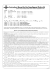
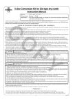
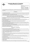
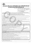
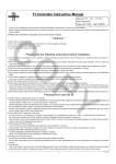
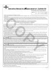
 Instruction Manual for Dry-Type Clutch Kit
Item Nos: 02−02−0121 For motorcycles with standard transmission
02−02−0141 For motorcyles with TAKEGAWA’S 6-speed transmission
Applicable Models & Frame Nos:
DREAM50 : AC15-1000001∼
CO
・Thank you for purchasing one of our TAKEGAWA's products. Please strictly follow the following instructions in installing and using the kit.
・Before fitting the kit, please be sure to check the kit contents. Should you have any questions about the products, please kindly contact your local motorcycle dealer.
Please read the following before starting the installation
◎ We do not take any responsibility for any accident or damage whatsoever arising from the use of the products not in conformity with the instructions in
the manual.
◎ We shall be held free from any responsibility or compensation whatsoever for any glitch in the parts other than ours if the glitch takes place after the installation and use of the products.
◎ If you make modifications to the products, we shall be held free from any guarantee of the products.
◎ You are kindly requested not to contact us about the combination of our products with other manufacturers'.
◎This kit is designed for exclusive use in the above-mentioned applicable models and frame numbers only. Please take note that this kit cannot be mounted
on other models. ◎ This kit cannot be installed along with a transmission of other manufacturers’ like HRC.
◎Installation of this kit requires engine removal and mounting, crankcase disassembly, and other work. Please prepare and strictly follow a HONDA genuine
parts service manual for your vehicle. In addtion, you need to prepare gaskets and packings suitable for the specifications of your vehicle.
◎ If the friction discs get covered with water, for example when running in the rain, clutch slipping may occur causing the clutch to be nonfunctional.
If possible, avoid running in the rain as much as possible, or when the driving in the rain is unavoidable, try to skirt puddles as much as possible to prevent
the friction discs from getting wet.
◎ Water adhering to friction discs, etc. will corrode these parts, rendering the clutch non-functional. Always wipe the water off the friction discs, a clutch
plate and other parts and dry them sufficiently after riding in the rain, or washing the motorcycle. In the humid or rainy seasons, store your vehicle with
the clutch disengaged to prevent the friction discs, the clutch plate and other parts from sticking to each other. ◎ When our TAKEGAWA’s oil cooler kit is used, the oil cooler outlet is usable as it is.
◎ Please be informed that, mainly because of improvement in performance, design changes, and cost increase, the product specifications and prices are
subject to change without prior notice.
◎ This Instruction Manual should be retained for future reference.
PY
∼ Features ∼
・As the clutch is located outside, the cooling effect is excellent. Moreover, since there is no oil resistance, it improves the clutch disengagement. In addition,
this dry-type clutch prevents oil from deteriorating caused by the wear of the clutch discs or the generated heat, and reduces adverse effect on the engine.
・We have designed the friction discs to be five in the number to be able to respond to a high-powered engine. In addition, by casting cast iron on the contact
surfaces of both the clutch center and the clutch pressure plate with the discs, we succeeded in doing without a clutch plate which has traditionally been
regarded as necessary, leading to reduction in the weight.
In addition, by compounding Kevlar fiber in the clutch friction discs, we have made the discs more durable than the conventional ones.
The increased friction factor leads to the decrease in the slipping, judders and noises generated when the clutch is engaged.
・We have incorporated a damper into the primary driven gear with an aim to reduce the shock felt at the time of clutch engagement.
・We have used a paper-type oil filter to improve the engine oil filterability. And we have created an oil pot to check the amount of oil left.
The following show the envisioned possibility of injuries to human bodies and property damage as a result of disregarding the
CAUTION following cautions.
・Please try to ride a motorcycle at legal speed on the public road, abiding by the law.
・Work only when the engine and muffler are cool. (Otherwise, you will burn yourself.)
・Prepare right tools for the work. (Otherwise, the installation with improper tools could cause breakage of parts or injuries to yourself.)
・Always use a torque wrench to screw bolts and nuts tight and securely to the specified torque.
(Improper torque could cause these parts to get damaged or fall off, resulting in accidents.)
・As some products and frames have sharp edges or protruding portions, please work with your hands protected.
(Otherwise, you will suffer injuries.)
・Before riding, always check every section for slack in parts like screws. If you find slack ones, screw them securely up to the specified torque.
(Otherwise, improper tightening may cause parts to come off.)
・Always use new gaskets, and packings. And check those parts to be reused for wear and damage. If you find worn or damaged parts, replace
them with new ones.
The following show the envisioned possibility of human death or serious injuries to human bodies as a result of disregarding the
WARNING following cautions.
・Those who are technically unskilled or inexperienced are required not to do the work.
(Improper installation because of insufficient skill and knowledge could lead to parts breakage and subsequently to accidents.)
・Rotating parts in the dry-type clutch, such as a clutch outer, are touchable through an opening in a cover. Please never look into or touch them when the engine is running. Moreover, be dressed to protect your legs when riding so you do not get your clothes caught in the rotating parts of
the clutch. (Otherwise, falling accidents, human injuries, or suffering of burns may occur.)
・Always start the engine in a well-ventilated place, and do not turn the engine on in an airtight place.
(Otherwise, you will suffer from carbon monoxide poisoning.)
・When you notice something abnormal with your motorcycle while riding, stop riding immediately and park your motorcyle in a safe place.
(Otherwise, the abnormality could lead to accidents.) ・Before doing work, make sure your bike is secure on level ground for safety's sake.
(Otherwise, your motorcycle could overturn and injure you while you are working.)
・Check or carry out maintenance of your motorcycle correctly according to the procedures in the Service Manual or service manual.
(Improper checking or maintenance could lead to accidents.)
・If you find damaged parts when checking and performing maintenance, do not use these parts any longer, and replace them with new ones.
(The continued use of these damaged parts could lead to accidents.)
-1-
Jun./02/’
07
∼ Kit Contents ∼
4
CO
5
6
39
30
3
1
40
32
43
31
42
7
22
STD
10
11
12
9
8
PY
23
24
25
20
34
35
33
14
16
17
13
41
18
20 21
15
19
44
45
45
45
46
45
45
No.
1
2
3
4
5
6
7
8
9
10
11
12
13
14
15
16
45
29 28
27 26
37
2
38
36
20
44
Part Name
Right crank case cover COMP.
Clutch cover COMP.
Right crank case cover gasket
Crank case gasket
Main shaft 13T
Primary driven gear COMP., 71T
Dowel pins, 8 x 14
Clutch outer
Flat head screws, 6 x 15
Set ring, 17 mm
Clutch pressure plate
Clutch plates
Kevlar clutch friction discs
Clutch center
External circlip
Clutch springs
Qty
1
1
1
1
1
1
2
1
6
1
1
4
5
1
1
4
No.
17
18
19
20
21
22
23
24
25
26
27
28
29
30
31
32
Part Name
Clutch lifter plate COMP.
Flange hex bolts, 6 x 22
Clutch release rack
Socket cap screws, 6 x 15
Clutch cable receiver
Oil filter spring
Oil filter
O-ring
Oil filter cover
Plain washer, 10 mm
Arm spring
Flange hex bolt, 6 x 18
Clutch release arm
Clutch cable COMP.
O-ring
Hole cap
-2-
Qty
1
4
1
6
1
1
1
1
1
1
1
1
1
1
1
1
No.
33
34
35
36
37
38
39
40
41
42
43
44
45
46
Tool
Part Name
Oil pot COMP.
Oil seal, 60 x 80 x 8
Oil seal, 18 x 29 x 7
Clutch release pinion
Oil seal, 10 x 17 x 5
Flat head screw, 4 x 10
Radial ball bearing, 17 x 30 x 7
Oil seal, 17 x 32 x 7
Sealed bearing
Oil seal, 12 x 20 x 5
Internal circlip, 22 mm
Socket cap screws, 6 x 40
Socket cap screws, 6 x 80 Socket cap screws, 6 x 100
Hex wrench, 5 mm
Qty
1
1
1
1
1
1
1
1
1
1
1
2
6
1
1
Jun./02/’
07
∼ Installation Procedures ∼
○ Check the kit contents.
(Clutch Installation)
○ Make sure the bike is secure on the sidestand during
installation.
1.Put a clutch outer into the main shaft and temporarily tighten it with 6x15 flat head screws. And screw them up diagonally to the specified
torque.
Torque=10 N・m (1.0 kgf・m)
(Transmission)
CO
1.According to the Honda’s genuine service manual (hereinafter,
Service Manual), demount the engine.
2.Attach a standard spline washer B to the main shaft first, and then a
kit's 17mm set ring.
2.Place the demounted engine on a secure stand or the like.
Disassemble the crankcases referring to the Service Manual, and take out the transmission.
3.To prevent axial direction from getting out of place, punch with a center punch about six points on the circumference surrounding the
bearings on the main shaft of the right crankcase. (Punch diagonally
six places about 2 mm from the outer circumference of the bearings.)
4.Change the standard transmission main shaft with the dry-type main
shaft of the kit.
※ Beware of the direction in which each gear is installed.
PY
like.
6.Fix the clutch spring to the boss of the clutch pressure plate.
6.Referring to the procedures described in the Service Manual, reinstall
the parts detached at the time of crankcase disassembly.
At this stage, leave the transmission main shaft bare of parts.
Apply engine oil to the tooth flank and ball bearing, and grease to the oil
seal, of the primary driven gear COMP, which please insert to the main shaft.
※Take off the masking tape on the primary driven gear COMP., wipe off the tape mark with thinner or the like, and then apply grease to the tape
mark lightly.
4.Holding the boss of a clutch pressure plate, align the protruding
portion of the clutch friction disk with the recessed portion of the clutch outer. At the same time, align the clutch center with the spline of
the main shaft, and insert the main shaft.
5.
Attach a kit's external circlip to the groove in the main shaft. Make sure
to place the circlip with the square side facing out.
※ Do not expand the external circlip more than necessary.
※ If the external circlip does not easily fit into the groove in the main shaft, fit it while pulling the main shaft with a needle nose plier or the
5.Install the transmission into the crankcases, replace the crankcase gasket with a new one, and assemble the crankcases.
(Installation of Primary Driven Gear)
3.Attach a clutch friction disc to the clutch center, and then a clutch plate alternately in this order, and a clutch pressure plate.
※Degrease the oil on the clutch plate thoroughly, since remaining oil on
the clutch plate will cause slipping.
※ Make sure that the clutch center and the clutch pressure plate are meshing with each other.
7.Fix the clutch lifter plate with 6x22 flange hex bolts with its bearings
facing outside, and screw them as tight as possible by hand.
Pull the clutch lifter plate toward you, and if there is a clearance between the friction disks, this shows that the clutch center and the
clutch pressure plate are not fitting together. Therefore, turn the clutch
lifter plate to the right or left a little until they fit each other. After making
sure they fit rightly, fix and gradually tighten the hex bolts diagonally
while pulling the clutch lifter plate toward you. Finally, tighten them to
the specified torque.
Torque: 12 N・m (1.2 kgf・m)
※In working, see to it that the clutch spring does not get out of position.
(Clutch Cable Installation)
1.Referring to the procedures in the Service Manual, reinstall the parts
which were were detached at the time of crankcase disassembly. Then mount the engine to the frame.
(Installation of Right Crank Case Cover)
1.Degrease the mating surfaces of the crankcase, and install two dowel
pins and a right crankcase cover gasket of the kit to the crankcase.
2.Attach the clutch cable receiver to the clutch cover COMP. with 6x15
2.Apply grease to the lip of each oil seal in the crankcase cover COMP.,
3.After making sure that the clutch release rack is inside the clutch cover COMP., fit the clutch cover COMP. firmly into the right crankcase
cover, and fix it by tightening 6x15 socket cap screws temporarily. Then, tighten up the screws to the specified torque. Torque=10 N・m (1.0 kgf・m)
※ Apply grease to the clutch release rack.
and put in the case cover straight along the main shaft with care not
to damage the oil seals. Then, temporarily fix it onto the crankcase with cap screws from the center to the outside diagonally to the
specified torque.
Torque: 10 N・m (1.0 kgf・m)
※ Fit the case with enough care since the oil seals of the right
crankcase cover COMP. sometimes get turned up.
socket cap screws, and tighten the screws to the specified torque.
4.Attach the clutch cable end to the clutch lever.
-3-
Jun./02/’
07
5.Route the clutch cable to the the receiver without pulling it forcibly.
(Final Checking after Installation)
6.Apply a little grease to the clutch cable end, and put the clutch
release arm into it.
※Fix the arm so its notch faces the back of the vehicle. Set the arm so
its notch faces the back of the vehicle.
1.With the engine turned off, shift the transmission to the first gear, and
hold the clutch lever. Then, check that the rear wheel rotates when you move the mahine, and that the rear wheel does not rotate when
you have released the clutch lever.
CO
7.Screw the adjuster of the clutch cable into the cable receiver to
the end.
8.Fix the release arm to the release pinion with the clutch arm
spring and the clutch cable inner stretched. Then fasten it by
tightening a 6x18 flange bolt to the specified torque.
2.
Shift the transmission into NEUTRAL, and start the engine. Then check
each section for oil leak. If nothing is wrong, do a test run at slow speed in a safe place to check the clutch operation.
Torque=10 N・m (1.0 kgf・m)
※ Install the release arm by aligning the serrations with each other.
If the arm is pressed inside forcibly without the serrations being aligned
with each other, then the release arm will get broken and unusable.
9.Adjust the free play at the clutch with the adjuster on the clutch
cable receiver, then install and tighten the locking nuts to the specified
torque. And cover the clutch cable adjusters at both ends with rubber
caps. Adjust the free play at the clutch lever end to be 10 to 20 mm.
(Oil Filter Installation)
PY
1.Put the oil filter spring inside the right crankcase cover.
Please see to it that it fits in the crankcase boss. Also attach the oil filter, and then fix the oil filter cover by tightening 6x15 cap screws to
the specified torque.
Torque=10 N・m (1.0 kgf・m)
※Place the oil filter so that it sticks in the protrusion on the oil filter cover.
※Unless the oil filter spring is set inside the protrusion on the oil filter, there will be a gap between the oil filter cover and the right crankcase
cover COMP. ※When replacing the oil filter, wipe off the oil on the surface of the right
crankcase cover COMP. which contacts the O-ring and the oil on the
oil filter cover, and then apply grease to the O-ring thinly.
2.Reinstall the parts which were detached at the time of engine
dismount, following the instructions in the Service Manual.
3.After checking that the drain bolt is tightened to the specified torque
[torque: 21.5 N・m (2.2 kgf・m)], add 1,100cc of engine oil, attach
the O-ring to the hole cap, and tighten it to the specified torque.
Torque=12 N・m (1.2 kgf・m)
※ Apply engine oil slightly to the O-ring of the hole cap.
※Inject 900 cc of engine oil when the crankcase is not disassembled or
at the time of oil change, and 1,000 cc of engine oil when the oil filter
is to be exchanged.
4.Detach the spark plug, and push down the kick-starter a few times
so the engine oil gets circulated all around the engine. And then, put back the spark plug where it was.
3-5-16 Nishikiorihigashi Tondabayashi
Osaka Japan
TEL : 81-721-25-1357
FAX : 81-721-24-5059
URL : http://www.takegawa.co.jp
Appropriate level of engine oil
seen through the oil pot.
-4-
Jun./02/’
07