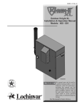
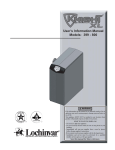
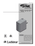
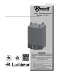
1
Installation & Operation Manual 6 Hydronic piping (continued) Figure 46 Multiple Boilers Zoned with Valves Model 80 105 150 210 285 399 500 2 Number of Units 3 4 5 6 Required Pipe Sizes 1-1/4" 1-1/2" 2" 2-1/2" 2-1/2" 1-1/2" 2" 2" 2-1/2" 2-1/2" 2" 2" 2-1/2" 2-1/2" 2-1/2" 2" 2-1/2" 2-1/2" 3" 3" 2-1/2" 2-1/2" 3" 3" 3-1/2" 2-1/2" 3" 3-1/2" 4" 4" 2-1/2" 3" 3-1/2" 4" 5" 35 Installation & Operation Manual 6 Hydronic piping Figure 47 Single Boiler - Non-Zoned Primary/Secondary Piping 36 Installation & Operation Manual 6 Hydronic piping (continued) Figure 48 Multiple Boilers - Non-Zoned Primary/Secondary Piping Model 80 105 150 210 285 399 500 2 Number of Units 3 4 5 6 Required Pipe Sizes 1-1/4" 1-1/2" 2" 2-1/2" 2-1/2" 1-1/2" 2" 2" 2-1/2" 2-1/2" 2" 2" 2-1/2" 2-1/2" 2-1/2" 2" 2-1/2" 2-1/2" 3" 3" 2-1/2" 2-1/2" 3" 3" 3-1/2" 2-1/2" 3" 3-1/2" 4" 4" 2-1/2" 3" 3-1/2" 4" 5" 37 Installation & Operation Manual 7 Gas connections Connecting gas supply piping Figure 50 Gas Supply Piping - Models 285 - 500 1. Remove the top access panel and refer to FIG.’s 49 and 50 to pipe gas to the boiler. a. Install ground joint union for servicing, when required. b. Install manual shutoff valve in gas supply piping outside boiler jacket when required by local codes or utility requirements. c. In Canada – When using manual main shutoff valves, it must be identified by the installer. Figure 49 Gas Supply Piping - Models 80 - 210 2. Support piping with hangers, not by the boiler or its accessories. WARNING The gas valve and blower will not support the weight of the piping. Do not attempt to support the weight of the piping with the boiler or its accessories. Failure to comply could result in severe personal injury, death, or substantial property damage. 3. Purge all air from the gas supply piping. 4. Before placing the boiler in operation, check the boiler and its gas connection for leaks. a. Close manual main shutoff valve during any pressure testing at less than 13 inches w.c. b. Disconnect the boiler and gas valve from the gas supply piping during any pressure testing greater than 13 inches w.c. WARNING Do not check for gas leaks with an open flame – use the bubble test. Failure to use the bubble test or check for gas leaks can cause severe personal injury, death, or substantial property damage. 5. Use pipe sealing compound compatible with propane gases. Apply sparingly only to male threads of the pipe joints so that pipe dope does not block gas flow. 38 Installation & Operation Manual 7 Gas connections (continued) WARNING Failure to apply pipe sealing compound as detailed in this manual can result in severe personal injury, death, or substantial property damage. WARNING Knight boilers are typically shipped ready to fire on natural gas. Check boiler rating plate to determine which fuel the boiler is set for. If set to natural gas, it may be converted to LP by installing an orifice (see page 12). In order to operate on LP gas, an orifice MUST BE installed. Failure to comply could result in severe personal injury, death, or substantial property damage. WARNING Use two wrenches when tightening gas piping at boiler (FIG. 51), using one wrench to prevent the boiler gas line connection from turning. Failure to support the boiler gas connection pipe to prevent it from turning could damage gas line components. Natural gas: Pipe sizing for natural gas 1. Refer to Table 7 for pipe length and diameter. Based on rated boiler input (divide by 1,000 to obtain cubic feet per hour). a. Table 7 is only for natural gas with specific gravity 0.60 inches, with a pressure drop through the gas piping of 0.5 inches w.c. b. For additional gas pipe sizing information, refer to ANSI Z223.1 (or B149.1 or B149.2 for Canadian installations). Natural gas supply pressure requirements 1. Pressure required at the gas valve inlet pressure port: • Maximum 10.5 inches w.c. with no flow (lockup) or with boiler on. • Minimum 4 inches w.c. with gas flowing (verify during boiler startup). 2. Install 100% lockup gas pressure regulator in supply line if inlet pressure can exceed 10.5 inches w.c. at any time. Adjust lockup regulator for 10.5 inches w.c. maximum. Figure 51 Inlet Pipe with Backup Wrench Propane Gas: WARNING Knight boilers are typically shipped ready to fire on natural gas. Check boiler rating plate to determine which fuel the boiler is set for. If set to natural gas, it may be converted to LP by installing an orifice (see page 12). In order to operate on LP gas, an orifice MUST BE installed. Failure to comply could result in severe personal injury, death, or substantial property damage. Pipe sizing for propane gas 1. Contact gas supplier to size pipes, tanks, and 100% lockup gas pressure regulator. Propane Supply Pressure Requirements 1. Adjust propane supply regulator provided by the gas supplier for 13 inches w.c. maximum pressure. 2. Pressure required at gas valve inlet pressure port: • Maximum 13 inches w.c. with no flow (lockup) or with boiler on. • Minimum 8 inches w.c. with gas flowing (verify during boiler startup). NOTICE Maximum inlet gas pressure must not exceed the value specified. Minimum value listed is for the purposes of input adjustment. 39 Installation & Operation Manual 7 Gas connections Table 7 Natural Gas Pipe Size Chart Single Unit Natural Gas Pipe Capacity Chart Length of Pipe in Straight Feet Nominal Iron Pipe Size (Inches) 10 20 30 40 50 60 70 80 90 100 125 150 175 200 1/2 175 120 97 82 N/A N/A N/A N/A N/A N/A N/A N/A N/A N/A 3/4 369 256 205 174 155 141 128 121 113 106 95 86 79 74 1 697 477 384 328 292 267 246 236 210 200 179 164 149 138 1-1/4 1400 974 789 677 595 543 502 472 441 410 369 333 308 287 1-1/2 2150 1500 1210 1020 923 830 769 707 666 636 564 513 472 441 2 4100 2820 2260 1950 1720 1560 1440 1330 1250 1180 1100 974 871 820 2-1/2 6460 4460 3610 3100 2720 2460 2310 2100 2000 1900 1700 1540 1400 1300 3 11200 7900 6400 5400 4870 4410 4000 3800 3540 3330 3000 2720 2500 2340 4 23500 16100 13100 11100 10000 9000 8300 7690 7380 6870 6150 5640 5130 4720 WARNING Knight boilers are typically shipped ready to fire on natural gas. Check boiler rating plate to determine which fuel the boiler is set for. If set to natural gas, it may be converted to LP by installing an orifice (see page 12). In order to operate on LP gas, an orifice MUST BE installed. Failure to comply could result in severe personal injury, death, or substantial property damage. Check inlet gas supply NOTICE WARNING CSA or UL listed flexible gas connections are acceptable, but you must exercise caution to ensure that the line has adequate capacity to allow your boiler to fire at full rate. Consult with local codes for proper installation or service procedures. DO NOT adjust or attempt to measure gas valve outlet pressure. The gas valve is factory-set for the correct outlet pressure. This setting is suitable for natural gas and propane, requiring no field adjustment. Attempting to alter or measure the gas valve outlet pressure could result in damage to the valve, causing potential severe personal injury, death, or substantial property damage. 3. 4. 5. 6. 7. 8. 9. The gas piping must be sized for the proper flow and length of pipe, to avoid excessive pressure drop. Both the gas meter and the gas regulator must be properly sized for the total gas load. 10. If you experience a pressure drop greater than 1 inch w.c., the meter, regulator, or gas line is undersized or in need of service. Perform the steps below when checking inlet gas supply: 11. 12. 1. 2. Turn the main power switch to the “OFF” position. Shut off gas supply at the manual gas valve in the gas piping to the appliance. 40 13. Loosen the set screw one (1) full turn from inside the pressure tap on top of the gas valve. Place the tubing of the manometer over the tap once the set screw is loosened as shown in FIG.’s 52 - 54. Slowly turn on the gas supply at the field installed manual gas valve. Turn the power switch to the “ON” position. Adjust the temperature set point on the control panel of the SMART SYSTEM control module to call for heat. Observe the gas supply pressure as the burner fires at 100% of rated input. Percent of burner input will be displayed on the control panel. Ensure inlet pressure is within specified range. Minimum and maximum gas supply pressures are specified in this section of the manual. If gas supply pressure is within normal range and no adjustments are needed, proceed on to Step 11. If the gas pressure is out of range, contact the gas utility, gas supplier, qualified installer or service agency to determine the necessary steps to provide proper gas pressure to the control. Turn the power switch to the “OFF” position. Shut off the gas supply at the manual gas valve in the gas piping to the appliance. Remove the manometer from the pressure tap on top of the gas valve. Re-tighten the set screw inside the pressure tap. Installation & Operation Manual 7 Gas connections WARNING (continued) When re-tightening the set screw, be sure to tighten securely to prevent gas leaks. Figure 54 Inlet Gas Supply Check - Model 500 Do not check for gas leaks with an open flame -- use the bubble test. Failure to use the bubble test or check for gas leaks can cause severe personal injury, death, or substantial property damage. 14. Turn on the gas supply at the manual gas valve. 15. Turn the power switch to the “ON” position. 16. Adjust the temperature set point on the control panel of the SMART SYSTEM control module to the desired water temperature so the appliance will call for heat. 17. Check burner performance by cycling the system while you observe burner response. The burner should ignite promptly. Flame pattern should be stable. Turn system off and allow burner to cool, then cycle burner again to ensure proper ignition and flame characteristics. Figure 52 Inlet Gas Supply Check - Models 80 - 285 Gas Pressure The gas pressure must remain between 4 inches w.c. (natural), 8 inches w.c (LP) minimum and 10.5 inches w.c. (natural), 13 inches w.c. (LP) maximum during stand-by (static) mode and while in operating (dynamic) mode. If an in-line regulator is used, it must be a minimum of 10 feet from the Knight boiler. It is very important that the gas line is properly purged by the gas supplier or utility company. Failure to properly purge the lines or improper line sizing, will result in ignition failure. The problem is especially noticeable in NEW LP installations and also in empty tank situations. This can also occur when a utility company shuts off service to an area to provide maintenance to their lines. Figure 53 Inlet Gas Supply Check - Model 399 Gas valve replacement The gas valve MUST NOT be replaced with a conventional gas valve under any circumstances. As an additional safety feature, this gas valve has a flanged connection to the venturi and blower. WARNING Failure to follow all precautions could result in fire, explosion, or death! WARNING DO NOT adjust or attempt to measure gas valve outlet pressure. The gas valve is factory-set for the correct outlet pressure. This setting is suitable for natural gas and propane, requiring no field adjustment. Attempting to alter or measure the gas valve outlet pressure could result in damage to the valve, causing potential severe personal injury, death, or substantial property damage. 41 Installation & Operation Manual 8 Field wiring WARNING NOTICE CAUTION ELECTRICAL SHOCK HAZARD – For your safety, turn off electrical power supply before making any electrical connections to avoid possible electric shock hazard. Failure to do so can cause severe personal injury or death. Wiring must be N.E.C. Class 1. Installation must comply with: 1. National Electrical Code and any other national, state, provincial, or local codes, or regulations. 2. In Canada, CSA C22.1 Canadian Electrical Code Part 1, and any local codes. Line voltage connections If original wiring as supplied with boiler must be replaced, use only type 105°C wire or equivalent. 1. Connect 120 vac power wiring to the line voltage terminal strip in the junction box, as shown in FIG. 55. Boiler must be electrically grounded as required by National Electrical Code ANSI/NFPA 70 – latest edition. 2. Provide and install a fused disconnect or service switch (15 amp recommended) as required by the code (see FIG. 55). Label all wires prior to disconnection when servicing controls. Wiring errors can cause improper and dangerous operation. 3. On Models 80 - 285 the boiler pump is shipped loose. Wire the boiler pump as shown in FIG. 55. 4. When connecting a domestic hot water (DHW) pump, connect the wiring to the line voltage terminal strip as shown in FIG. 55. 5. To activate a system pump, wire as shown in FIG. 55. If the motor is larger than 1/3 HP, you must install a relay. Figure 55 Line Voltage Field Wiring Connections 42 Installation & Operation Manual 8 Field wiring (continued) Low voltage connections DHW thermostat 1. Route all low voltage wires through the knockouts in the rear of the boiler, as shown in FIG. 56. 1. Connect storage indirect water heater (DHW) thermostat (FIG. 57) to the DHW thermostat terminals on the connection board. 2. Connect low voltage wiring to low voltage connection board as shown in FIG. 57 on page 45 of this manual and the boiler wiring diagram. Auxiliary device relay Figure 56 Routing Field Wiring 1. If an auxiliary device (e.g., louvers) needs to operate when the boiler fires, it can be controlled by this output. Connect these terminals to a 24 vac relay coil, which is wired to operate the auxiliary device (FIG. 57). Auxiliary device proving switch 1. When the operation of an auxiliary device needs to be verified before the boiler fires, remove the jumper wire from these terminals and connect them to the normally open contacts on its proving switch (FIG. 57). High gas pressure switch Thermostat 1. Connect the room thermostat or end switch (isolated contact only) to terminals R and W, as shown in FIG. 57. 2. Install the thermostat on the inside wall away from influences of drafts, hot or cold water pipes, lighting fixtures, television, sunlight, or fireplaces. 3. Thermostat anticipator (if applicable): a. If connected directly to boiler, set for 0.1 amps. b. If connected to relays or other devices, set to match total electrical power requirements of connected devices. See device manufacturers’ specifications and thermostat instructions for details. 1. If a switch is provided to detect excessive gas pressure, remove the jumper wire from the terminals on the connection board, and then connect them to its normally closed contacts (FIG. 57). Low gas pressure switch 1. If a switch is provided to detect low gas pressure, remove the jumper wire from the terminals on the connection board and connect them to its normally open contacts (FIG. 57). 2. If both a high and low gas pressure switch are used, connect their respective contacts in series, and connect them to the terminals on the connection board (FIG. 57). Flow switch Outdoor temperature sensor 1. Connect outdoor temperature sensor (FIG. 57) to the outdoor sensor terminals on the connection board to enable outdoor reset operation of the Knight boiler. If fixed temperature operation is required, do not install outdoor sensor. 1. A flow switch is used to guarantee flow through the boiler before allowing it to fire. The flow switch must be installed in line with the boiler 2. Connect these terminals to the normally open contacts on the flow switch (FIG. 57). 2. Mount the sensor on an exterior wall, shielded from direct sunlight or flow of heat or cooling from other sources. 3. Route sensor wires through a knockout at the rear of the boiler (see FIG. 56). 43 Installation & Operation Manual 8 Field wiring (continued) System supply sensor 1. By installing an optional system supply sensor into the supply of the primary loop, the temperature of the primary supply can be controlled. The SMART SYSTEM control automatically detects the presence of this sensor, and controls the boiler firing rate to maintain the system supply temperature to the set point (if the outlet sensor control is currently selected). 2. Connect these terminals to the system supply sensor (FIG. 57). Boiler management system 1. An external control may be connected to control either the firing rate or the set point of the boiler. Connect the Room Thermostat / Zone Control terminals to the enable output of the external control and connect the 0 - 10 vdc terminals to the 0 - 10 vdc output of the external control. 2. Make sure the ground terminal is connected to the ground output terminal of the external control, and the 0 - 10 vdc terminal is connected to the 0 - 10 vdc terminal of the external control. Runtime contacts The SMART SYSTEM control closes a set of dry contacts whenever the burner is running. This is typically used by Building Management Systems to verify that the boiler is responding to a call for heat. Alarm contacts The SMART SYSTEM control closes another set of contacts whenever the boiler is locked out or the power is turned off. This can be used to turn on an alarm, or signal a Building Management System that the boiler is down. 44 Installation & Operation Manual 8 Field wiring (continued) Figure 57 Low Voltage Field Wiring Connections 45 Installation & Operation Manual 9 Condensate disposal Condensate drain NOTICE 1. This boiler is a high efficiency appliance that produces condensate. 2. The side of the boiler has a 1/2 inch PVC union for connection of a 1/2 inch PVC pipe (FIG. 58). 3. Slope condensate tubing down and away from the boiler into a drain or condensate neutralizing filter. Condensate from the Knight boiler will be slightly acidic (typically with a pH from 3 to 5). Install a neutralizing filter if required by local codes. A Neutralizer Kit is available from the factory (Kit #4004). 4. Install the 1/2 inch PVC tee assembly (shipped with the unit) as shown in FIG. 58. 5. Leave the top of the 1/2 inch tee OPEN. This is needed as a vacuum break. 6. Do not expose condensate line to freezing temperatures. 7. Use only plastic tubing or piping as a condensate drain line (FIG. 58). Figure 58 Condensate Disposal 46 NOTICE Use materials approved by the authority having jurisdiction. In the absence of other authority, PVC and CPVC pipe must comply with ASTM D1785 or D2845. Cement and primer must comply with ASME D2564 or F493. For Canada use CSA or ULC certified PVC or CPVC pipe, fittings, and cement. To allow for proper drainage on large horizontal runs, a second line vent may be required and tubing size may need to increase to 1 inch. The condensate line must remain unobstructed, allowing free flow of condensate. If condensate is allowed to freeze in the line or if the line is obstructed in any other manner, condensate can exit from the boiler tee, resulting in potential water damage to property. 8. A condensate removal pump is required if boiler is below drain. When installing a condensate pump, select one approved for use with condensing boilers and furnaces. The pump should have an overflow switch to prevent property damage from condensate spillage. The switch should be wired to the auxiliary device proving switch terminals on the low voltage connection board. Installation & Operation Manual 10 Start-up Check/control water chemistry Do not use petroleum-based cleaning or sealing compounds in the boiler system. Damage to elastomer seals and gaskets in the system could occur, resulting in substantial property damage. Hardness less than 7 grains CAUTION 1. Consult local water treatment companies for hard water areas (above 7 grains hardness). Chlorine concentration less than 200 ppm 1. Do not fill boiler or operate with water containing chlorine in excess of 200 ppm. 2. Filling with chlorinated fresh water should be acceptable since drinking water chlorine levels are much lower. 3. Do not use the boiler to directly heat swimming pool or spa water. Test/replace freeze protection fluid 1. For systems using freeze protection fluids, follow fluid manufacturer’s instructions. 2. Freeze protection fluid must be replaced periodically due to degradation of inhibitors over time. Follow all fluid manufacturer’s instructions. Freeze protection (when used) 1. Determine freeze protection fluid quantity using system water content, following fluid manufacturer’s instructions. Boiler water content is listed on page 7. Remember to include expansion tank water content. 2. Local codes may require a backflow preventer or actual disconnect from city water supply. 3. When using freeze protection fluid with automatic fill, install a water meter to monitor water makeup. Freeze protection fluid may leak before the water begins to leak, causing concentration to drop, reducing the freeze protection level. Fill and test water system 4. At initial fill and during boiler startup and testing, check system thoroughly for any leaks. Repair all leaks before proceeding further. WARNING Eliminate all system leaks. Continual fresh makeup water will reduce boiler life. Minerals can build up in the heat exchanger, reducing heat transfer, overheating the heat exchanger, and causing heat exchanger failure. Purge air from water system 1. Purge air from system: a. Connect a hose to the purge valve (see purge/drain valves, in piping diagrams on pages 32 through 37). Route the hose to an area where water can drain and be seen. b. Close the boiler or system isolation valve between the purge valve and fill connection to the system. c. Close zone isolation valves. d. Open quick-fill valve on cold water makeup line. e. Open purge valve. f. One zone at a time, open the isolation valves. Allow water to run through the zone, pushing out the air. Run until no noticeable air flow is present. Close the zone isolation valves and proceed with the next zone. Follow this procedure until all zones are purged. g. Close the quick-fill water valve and purge valve and remove the hose. Open all isolation valves. Watch that system pressure rises to correct cold-fill pressure. h. After the system has operated for a while, eliminate any residual air by using the manual air vents located throughout the system. i. If purge valves are not installed in the system, open the manual air vents in the system one at a time, beginning with the lowest floor. Close the vent when water squirts out. Repeat with remaining vents. 2. Open automatic air vent (diaphragm-type or bladdertype expansion tank systems only) one turn. 1. Fill system only after ensuring the water meets the requirements of this manual. 3. Open other vents: a. Starting on the lowest floor, open air vents one at a time until water squirts out. b. Repeat with remaining vents. 2. Close manual and automatic air vents and boiler drain valve. 4. Refill to correct pressure. 3. Fill to correct system pressure. Correct pressure will vary with each application. a. The minimum cold water fill pressure for a residential system is 12 psi. b. Pressure will rise when boiler is turned on and system water temperature increases. 47 Installation & Operation Manual 10 Start-up (continued) Check for gas leaks WARNING Before starting the boiler, and during initial operation, smell near the floor and around the boiler for gas odorant or any unusual odor. Remove the top access panel and smell the interior of the boiler enclosure. Do not proceed with startup if there is any indication of a gas leak. Use an approved leak detection solution. Repair any leaks at once. WARNING DO NOT adjust or attempt to measure gas valve outlet pressure. The gas valve is factory set for the correct outlet pressure. This setting is suitable for natural gas and propane, requiring no field adjustment. Attempting to alter or measure the gas valve outlet pressure could result in damage to the valve, causing potential severe personal injury, death, or substantial property damage. Figure 59 Condensate Trap WARNING Propane boilers only – Your propane supplier mixes an odorant with the propane to make its presence detectable. In some instances, the odorant can fade, and the gas may no longer have an odor. Before startup (and periodically thereafter), have the propane supplier verify the correct odorant level in the gas. Check thermostat circuit(s) 1. Disconnect the two external wires connected to the room thermostat terminals on the connection board. 2. Connect a voltmeter across these two incoming wires. Close each thermostat, zone valve, and relay in the external circuit one at a time and check the voltmeter reading across the incoming wires. 3. There should NEVER be a voltage reading. 4. If a voltage does occur under any condition, check and correct the external wiring. (This is a common problem when using 3-wire zone valves.) 5. Once the external thermostat circuit wiring is checked and corrected if necessary, reconnect the external thermostat circuit wires to the connection board. Allow the boiler to cycle. Inspect/fill condensate system Inspect/check condensate lines and fittings 1. Inspect the condensate drain line, condensate PVC fittings and condensate trap. Fill condensate trap with water 1. Remove the PVC cap retaining screw from the PVC cap (FIG. 59). 2. Remove the 2 inch PVC cap with the switch located at the top of the trap (FIG. 59). 3. Fill with fresh water until the water begins to pour out of the drain. 4. Replace the cap. Press the cap onto the trap until the cap makes contact with the drain. 5. Replace the retaining screw. WARNING 48 The condensate trap (FIG. 59) must be filled with water during all times of boiler operation to avoid flue gas emission from the condensate drain line. Failure to fill the trap could result in severe personal injury or death. Installation & Operation Manual 10 Start-up (continued) Final checks before starting the boiler Check vent piping and air piping Read the Knight Boiler Service Manual to familiarize yourself with SMART SYSTEM control module operation. Read this manual, pages 50 and 51 for proper steps to start boiler. 1. Check for gastight seal at every connection, seam of air piping, and vent piping. WARNING Verify the boiler and system are full of water and all system components are correctly set for operation. Verify the preparation procedures of Section 10, pages 47 and 48 have been completed. Fill the vent condensate trap with water (removing the retaining screw in order to remove the 2 inch PVC cap with the switch located at the top of the trap). Replace the cap. Press the cap onto the trap until the cap makes contact with the drain. Replace the retaining screw. Check gas piping 1. Check around the boiler for gas odor following the procedure on page 38 of this manual (connecting gas supply piping). WARNING Verify electrical connections are correct and securely attached. Inspect vent piping and air piping for signs of deterioration from corrosion, physical damage or sagging. Verify air piping and vent piping are intact and correctly installed per this manual. Start the boiler 1. Read and follow the Operating instructions in FIG.’s 60 and 61, pages 50 and 51. If boiler does not start correctly 1. Check for loose connections, blown fuse or service switch off? 2. Is external limit control (if used) open? Is boiler water temperature above 200°F? 3. Is thermostat set below room temperature? 4. Is gas turned on at meter or boiler? 5. Is incoming gas pressure less than 4 inches w.c.? If none of the above corrects the problem, refer to the Troubleshooting Section of the Knight Boiler Service Manual. Check system and boiler Check water piping 1. Check system piping for leaks. If found, shut down the boiler and repair immediately. (See WARNINGS on pages 47 and 48 (startup) regarding failure to repair leaks.) 2. Vent any remaining air from the system using manual vents. Air in the system will interfere with circulation and cause heat distribution problems and noise. Venting system must be sealed gastight to prevent flue gas spillage and carbon monoxide emissions, which will result in severe personal injury or death. If you discover evidence of any gas leak, shut down the boiler at once. Find the leak source with a bubble test and repair immediately. Do not start the boiler again until corrected. Failure to comply could result in severe personal injury, death, or substantial property damage. Propane boilers – verify conversion 1. Verify propane conversion has been completed per the Propane Conversion instructions. WARNING DO NOT adjust or attempt to measure gas valve outlet pressure. The gas valve is factory-set for the correct outlet pressure. This setting is suitable for natural gas and propane, requiring no field adjustment. Attempting to alter or measure the gas valve outlet pressure could result in damage to the valve, causing potential severe personal injury, death, or substantial property damage. WARNING Knight boilers are typically shipped ready to fire on natural gas. Check boiler rating plate to determine which fuel the boiler is set for. If set to natural gas, it may be converted to LP by installing an orifice (see page 12). In order to operate on LP gas, an orifice MUST BE installed. Failure to comply could result in severe personal injury, death, or substantial property damage. Check flame and combustion 1. Turn the main power off to the boiler by placing the “On/Off ” switch in the OFF position. 2. Remove the flue temperature sensor from the flue pipe connection. Note: Combustion measurements will be made at this point. 3. Turn the main power on to the boiler by placing the “On/Off ” switch in the ON position. 49 Installation & Operation Manual 10 Start-up Figure 60 Operating Instructions - Models 80 - 285 50 Installation & Operation Manual 10 Start-up (continued) Figure 61 Operating Instructions - Models 399 - 500 51 Installation & Operation Manual 10 Start-up Check flame and combustion (continued) Set space heating operation 4. Place the boiler into the active position by pressing the SHUTDOWN button on the display board (FIG. 62, page 59) until BOILER:Standby appears in the display window. Determine controlling sensor 5. Locate the pinhole button above the “T” in the Knight logo on the display board (FIG. 62). Press the button once and hold for 5 seconds to place the boiler into Service Mode. In Service Mode the boiler will fire at ignition speed and will then modulate up to full fire. 6. Insert the probe from a combustion analyzer into the hole left by the removal of the flue temperature sensor. 7. Once the boiler has modulated up to full fire, measure the combustion. The values should be in the range listed in Table 8 below. The CO levels should be less than 150 ppm for a properly installed unit. If the combustion is not within the specified range, reference the Troubleshooting Section of the Knight Boiler Service Manual for possible causes and corrective actions. Table 8 Flue Products Chart Natural Gas Propane CO2 min. CO2 max. O2 min. O2 max. CO2 min. CO2 max. O2 min. O2 max. 8.0% 10.0% 3.0% 6.5% 8.0% 11.0% 4.0% 8.5% 8. Once the combustion analysis is complete, press the SHUTDOWN button on the display board (FIG. 62) to take the boiler out of Service Mode. The boiler will go to shutdown and the display will show BOILER:OFF. 9. Turn the main power off to the boiler and replace the flue temperature sensor into the flue pipe connection. 10. Place the boiler back into normal operation. WARNING 52 You must replace the flue gas temperature sensor to prevent flue gas spillage into the room. Failure to comply could result in severe personal injury, death, or substantial property damage. For space heating systems, the temperature control can be based on one of three sensors; the inlet, outlet, or (optional) system sensor. The SMART SYSTEM control is programmed at the factory to control the temperature of the outlet sensor. The control will automatically switch to the system sensor once it is connected. If it is desired to base the temperature control on the inlet sensor, the appropriate parameter must be changed in the control. See the Knight Boiler Service Manual for a detailed explanation of this procedure. Verify space heat circulator mode The Space Heating Mode controls both the system (primary) pump (if connected), and the boiler (secondary) pump. When the SMART SYSTEM control receives a space heating call for heat, it turns on the system pump. If the boiler is not heating an indirect DHW (Domestic Hot Water) tank, it also turns on the boiler pump. After the space heating call for heat ends, the system pump continues to run for a short period of time. If the boiler pump was running, it continues to run for a short period of time as well. These pump delays are factory set to 30 seconds. If different delays are desired, the appropriate parameters in the control must be changed. See the Knight Boiler Service Manual for a detailed explanation of this procedure. Set space heating set point temperature The UP and DOWN keys may be used during normal operation to adjust the space heating set point temperature. Once the desired temperature is displayed, press the ENTER/RESET key to save the new setting. If the ENTER/RESET key is not pressed, the new setting will be used for the current heating cycle only. The old setting will become active after the current heating cycle ends. Installation & Operation Manual 10 Start-up (continued) Set domestic hot water (DHW) operation Verify DHW circulator mode The DHW Mode is programmed to heat an indirect domestic hot water tank. When the tank thermostat calls for heat, the SMART SYSTEM control will turn on the DHW pump and turn off the boiler pump (if running). If the system pump is running, it will remain on. When the DHW call for heat ends, and there is no space heating call for heat, the DHW pump will continue to run for a period of time. This pump delay is set at the factory to 30 seconds. If a shorter or longer delay is desired, the appropriate parameter in the control must be changed. See the Knight Boiler Service Manual for a detailed explanation of this procedure. If there is an active space heating call for heat, then the boiler pump will be turned on and the DHW pump will be turned off. Set DHW target temperature 9. The date and time are displayed as “YY:MM:DD W hh:mm”, where: mm: minutes hh: hour (24 hour time; e.g., 2:00 PM = 14:00) W: day of the week (1 = Sunday, 2 = Monday, 3 = Tuesday, etc.,) DD: date MM: month YY: year Use the UP and DOWN keys to increment or decrement the flashing number, and the NEXT and PREVIOUS keys to select which number flashes. 10. Press the ENTER key to save the setting. 11. Press the MENU key twice to exit the Programming Mode. When in the DHW Mode, the control will modulate to maintain the outlet temperature to a set point. This set point is set at the factory to 180°F. If a different set point is desired, the appropriate parameter in the control must be changed. See the Knight Boiler Service Manual for a detailed explanation of this procedure. Set clock The SMART SYSTEM control has a built-in clock that it uses for its night setback feature and for logging events. This clock must be set when the boiler is installed, and anytime the boiler has been powered off for more than one month. Use the following procedure to set the clock: 1. Press and hold the MENU key for a least 5 seconds. 2. The display changes to ready “ENTER MENU CODE”, with four (4) zeros below it. 3. Change the zeros to match the user code (factory set at “0704”). Use the UP and DOWN keys to increment or decrement the flashing digit, and the NEXT and PREVIOUS keys to select which digit flashes. 4. Press the ENTER key. 5. The display changes to read USER CODE for a few seconds, then displays a menu. 6. Press the ENTER key. 7. Press the UP key twice to display “A3 DATE AND TIME”. 8. Press the ENTER key once. 53 Installation & Operation Manual 11 Operating information General How the boiler operates The Knight boiler uses an advanced stainless steel heat exchanger and electronic control module that allows fully condensing operation. The blower pulls in air and pushes flue products out of the boiler through the heat exchanger and flue piping. The control module regulates blower speed to control the boiler firing rate. The gas valve senses the amount of air flowing into the boiler and allows only the right amount of gas to flow. How the control module operates The SMART SYSTEM control module receives input from boiler sensors and external inputs. The control module activates and controls the blower and gas valve to regulate heat input and switches the boiler, Domestic Hot Water (DHW), and system pumps on and off as needed. The user programs the module to meet system needs by adjusting control parameters. These parameters set operating temperatures and boiler operating modes. Boiler operation can be based on boiler outlet water temperature, boiler inlet water temperature, or system temperature, depending on the parameter setting. Control inputs and outputs Room thermostat / zone control This input tells the boiler to provide water for space heating. Domestic Hot Water (DHW) tank thermostat This input tells the boiler to provide water for heating an indirect DHW tank. 0 - 10V input (set point or power) The Knight boiler can be controlled by a Building Management System (BMS) using a 0 - 10 vdc signal. The control can be configured by the installer to use this signal to either control set point or firing rate. DHW priority The SMART SYSTEM control module allows connection of a DHW thermostat to the low voltage connection board. When the DHW thermostat calls for heat, the module activates the DHW pump, shuts down the boiler pump, and immediately sets the target outlet water temperature to 180°F. This provides automatic priority heat allocation to the` indirect water heater for maximum response and recovery. The DHW pump continues for 30 seconds after the heating cycle to deliver the most possible heat. 54 DHW / space heating (SH) cycling If a DHW call for heat is received while a space heating call is in progress, the control will start the DHW pump and shut the boiler pump off. The system pump will remain on. If the space heating call is still active while the DHW call is in operation, the control will wait for 30 minutes (time adjustable by installer) then it will switch back to the space heating demand. The control will switch back and forth until one of the heat demands end. Programmable controlling sensor The control module is programmed to use the outlet sensor as the control sensor by default. If a system sensor is connected, the control automatically uses it as the control sensor. The control sensor can be changed by the installer to the inlet sensor. Anti-cycling After a space heating demand has been satisfied, the control will delay the next space heating call for a set time period (time is adjustable by the installer). The time delay will be bypassed if the inlet water temperature drops too far during the delay. Boiler, system, and DHW pump control When a space heating call for heat starts and no DHW call is on, the system and boiler pumps are turned on. As long as the space heating call for heat is on, the system pump will remain on. If a DHW call for heat is on, the boiler pump will wait to turn on until just before the DHW pump turns off. After the space heating call for heat ends, both pumps will run for an additional period of time. When a DHW call for heat starts, the DHW pump is turned on. If a space heating call for heat was on, the boiler pump will turn off a few seconds after the DHW pump turns on. Temperature control Modulation The Knight boiler is capable of modulating its firing rate from a minimum of 20% to a maximum of 100%. The firing rate is dictated by the call for heat (i.e., space heating or domestic hot water), the heating load, ramp delay (if enabled), and various other temperature limitations. Installation & Operation Manual 11 Operating information Ramp delay For systems with lower flow, the SMART SYSTEM can limit the firing rate (when enabled) when a space heating call for heat starts, or when switching from a DHW call for heat to a space heating call for heat. There are six (6) limits that can be programmed, as well as six (6) time intervals corresponding to each limit. The sixth limit will also limit the firing rate for the rest of the call for heat. Gradient limiting If during operation of the boiler the outlet water temperature is rising too quickly, the control will reduce the firing rate to its lowest setting. Outdoor air reset With the outdoor air sensor connected, the control module will calculate the set point based on the programmed reset curve. The installer can change the slope of the reset curve by several adjustable parameters. The user can limit the maximum set point for the system using the space heating set point. Boost function If outdoor air reset is active, and a space heating demand has been active continuously for a set period of time (time adjustable by installer) and there has been no DHW demands, the control will increase the set point by a fixed number of degrees (adjustable by installer). This process will continue until the space heating demand ends, the set point reaches the programmed set point, or a maximum of 20 increases has occurred. Once the system heat demand is satisfied, the set point will revert to the value determined by the reset curve. (continued) Protection features Outlet temperature, flue temperature rise limiting The control module monitors the flue temperature by a sensor located in the flue exhaust. If the flue temperature exceeds 215°F the control will reduce the maximum fan speed. If the flue temperature exceeds 240°F the control will shut the unit down. The unit will restart automatically once the flue temperature drops 25°F and the minimum off time has expired. The control monitors the temperature difference between the inlet and the outlet sensor. If this difference exceeds 55°F the control will reduce the fan speed. If the temperature difference exceeds 60°F the control will shut the unit down. The unit will restart automatically once the temperature difference has dropped below 55°F and the minimum off time has expired. Freeze protection DO NOT install the boiler in a room likely to freeze. The following integral feature of the SMART SYSTEM control module provides some protection for the boiler only -- not for the system. • • The controller may be programmed to reduce the space heating set point during a certain time each day. A start and stop time can be programmed for each day of the week. • • To prevent nuisance shutdowns when the boiler is firing at minimum rates, the control will increase fan speed when the flame signal drops too low. and The outlet temperature is monitored by the boiler outlet temperature sensor. When the outlet temperature exceeds 190°F, the unit will reduce the fan speed. If the outlet water temperature exceeds 193°F the control will shut the unit down until it cools off. Night setback Flame current support temperature, The SMART SYSTEM control module provides freeze-up protection as follows when the boiler water temperature drops below 45°F: Below 45°F, the boiler and system pumps operate constantly. Below 37°F, the boiler turns on. Boiler and pumps turn off if boiler water temperature rises above 45°F. CAUTION This feature of the SMART SYSTEM control module does not eliminate the possibility of freezing. The installation must still use recognized design, installation and maintenance practice to prevent freeze potential for the boiler and system. 55 Installation & Operation Manual 11 Operating information Monitor external limits Boiler temperature regulation Connections are provided on the connection board for external limits such as flow switch, low water cutoff, gas pressure switches, and an auxiliary device proving switch. The SMART SYSTEM will shut off the burner and inhibit relighting whenever any of these external limits open. Operating temperature (target) The SMART SYSTEM control module senses water temperature and regulates boiler firing and firing rate to achieve a target temperature. The target temperature can be set between 70°F and 190°F. Run-time and alarm outputs The boiler provides dry contacts for indicating when the boiler is running, and when it is unable to operate. Run-time and cycle counting The control uses two timers to monitor the total hours of burner operation. One timer monitors the time the boiler is firing under 50% of rate. The other timer monitors the time the boiler is firing over 50% rate. The control uses four (4) ignition counters to monitor the amount of boiler cycles. The first counter counts all ignitions of the control. The second counter counts only ignition attempts that have failed. The third and fourth counters are the same as the first and second respectively, but can be reset by the installer. • Target temperature is fixed when the outdoor sensor is not installed. • Target temperature is calculated as described below under “Outdoor Reset Operation” and “Target Temperature Boost” when the outdoor sensor is connected. High limit operations When outlet temperature exceeds 200°F, high limit action occurs. The boiler shuts down until the outlet water cools down. If local codes require manual reset, an Adjustable Manual Reset High Limit Kit is available. Low water cutoff protection Service reminder The control can be programmed for service reminder notification. This notification will become active when either a set time frame has expired, or a set amount of running hours or cycles has expired (all adjustable by the installer). The display will alternate the standard text on the display screen with Service Due every 5 seconds. The service reminder notification can be reset by the installer. Error logging The control will hold in memory the last 10 error codes as well as the last 10 turn-off functions. The date and time of the occurrence will be recorded as well. Only the 10 most current occurrences will be held in memory. 1. The SMART SYSTEM control module uses temperature sensing of both supply and return areas of the heat exchanger. If the flow rate is too low or either temperature too high, the control module modulates and shuts the boiler down. This ensures boiler shutdown in the event of low water or low flow conditions. 2. Some codes and jurisdiction may accept these integral features of the control in lieu of requiring an additional limit control or low water cutoff. Consult local jurisdiction to determine. A low water cutoff kit(s) is available (Kit #3057). Outdoor reset operation, if used Target temperature with outdoor reset This feature improves the system’s efficiency as the outdoor temperature warms up. See Knight Boiler Service Manual to change the settings. Reset curve The reset curve looks at outdoor air temperature and adjusts the set point. 56 Installation & Operation Manual 11 Operating information (continued) Sequence of operation OPERATION 1. Upon a call for heat, the control turns on the appropriate pumps (system and boiler pumps for space heating call; DHW pump for DHW call). 2. The control connects 120 vac to the blower. The blower does not run at this time. • If the unit is equipped with a flow switch or low water cutoff, it must close before the control powers up the blower. • If the unit is equipped with a manual reset high limit it must be closed before the control powers up the blower. • If the unit is equipped with a solenoid valve and/or a vent valve, they will be energized along with the blower. • If the unit is equipped with a gas pressure switch, it must close at this time. • If there is an auxiliary device connected to the unit, the unit will then provide 24 vac to its enable relay. If the auxiliary device has a proving switch, it must close before the sequence continues. DISPLAY BLR: Standby OUT: 123.8F(129) BLR: Standby OUT: 123.8F(129) 3. The control then starts a 10 second prepurge cycle. BLR: PREPURGE OUT: 123.9F(129) 4. Once the prepurge cycle is complete, and the blocked drain and auto-reset high limit are closed, the control starts the 5 second trial for ignition by sending spark voltage to the spark electrode and opening the gas valve. BLR: IGNITION OUT: 123.9F(129) 5. If the control does not detect flame by the end of the trial for ignition, the control performs a 10 second postpurge, another prepurge and tries to light the burner again. If the burner does not light after 4 trials (1 trial on the 500 model), the control locks out for 1 hour and then tries another set of 4 trials, except on the 500 model which is 100% lockout. 6. If the control detects a flame before the trial for ignition ends, it begins to modulate the burner in order to maintain the set point. If the boiler lights due to a space heating call for heat, and the ramp delay function is active (default is active), the modulation will be held to a series of increasing limits after the burner has lit. 7. If the space heating call for heat is active, and the DHW thermostat closes, the control will turn on the DHW pump, wait 2 seconds, and then turn off the boiler pump. This will divert the hot water away from the heating zone(s) and send it to the DHW tank instead. The control will then modulate to maintain the outlet temperature to the DHW boiler set point. BLR: POSTPURGE, PREPURGE OUT: 123.9F(129) BLR: SH 20% RATE OUT: 124.8F(129) BLR: DHW 85% RATE OUT: 177.8(180) 57 Installation & Operation Manual 11 Operating information Sequence of operation (continued) OPERATION DISPLAY 8. If the DHW thermostat remains on for more than 30 minutes, and the space heating call for heat is also on, then the control will turn on the boiler pump, turn off the DHW pump after 2 seconds, and resume modulating based on the space heating set point. As long as both the space heating and DHW calls for heat remain active, the control will switch back and forth between the two modes until one of them is satisfied. BLR: SH 41% RATE OUT: 123.0F(129) 9. Once both calls for heat are satisfied, the control will turn off the burner. The blower will remain on for the 10 second postpurge cycle. Any pumps that are running will continue to run for their respective pump delay times, then turn off. BLR: POSTPURGE OUT: 127.4F(129) 10.Boiler pump off, system pump continues its delay if longer. BLR: Standby OUT: 124.7F(129) 11. System pump off. BLR: Standby OUT: 122.9F(129) 58 Installation & Operation Manual 11 Operating information (continued) Knight boiler control module Use the control panel (FIG. 62) to set temperatures, operating conditions, and monitor boiler operation. Figure 62 Control Panel 59 Installation & Operation Manual 11 Operating information Access modes User The user can adjust space heating target temperature by using the UP and DOWN buttons (FIG. 62) at any time during normal operation. By entering the USER code (0704), the user can also change temperature units, time and date, and night setback settings. In User Mode, the following parameters can be viewed but not changed: • Boiler outlet water target temperature in DHW Mode • Boiler model number • Software version • Total operating hours • Total cycles Installer Most parameters are available only to the installer, accessible only by entering the installer access code, see the Knight Boiler Service Manual. Saving parameters (reference the Parameter Table in the Knight Boiler Service Manual) To save parameters and exit programming: Press the ENTER/RESET button. To keep parameter settings only for a current operating cycle: Press the MENU/EXIT button 3 times after making all desired parameter changes. To enter a parameter and continue programming: Press the MENU/EXIT button 1 time to return to the parameter listings; press again to return to the menu listings. Remember to press the ENTER/RESET button when finished programming in order to save the changes made. See the Knight Boiler Service Manual for a detailed description of parameters and access modes. 60 Installation & Operation Manual 11 Operating information (continued) Status Display Screens By using the Previous/Next (, ) arrow keys on the SMART SYSTEM display panel, you can navigate through the eight (8) display screens. Each screen will contain two (2) viewable items. The following is a description of the individual items and what they can display: Screen Display shows: Description BLR: OFF The unit has been turned OFF by the Enter/Reset button on the SMART SYSTEM display panel. Standby The unit has not received a call for heat from a remote thermostat nor has it received a call for heat from a DHW thermostat. Set Point Met The unit has met the water temperature set point, but is still receiving a call for heat from either a remote thermostat or a DHW thermostat. Prepurge The unit has initiated a 10 second purge period on a call for heat. Ignition The unit has begun a 5 second spark period to ignite the main burner. SH***% Rate The unit has fired and is running at the displayed percentage. Postpurge The call for heat has been satisfied and the unit runs the fan for an additional 10 seconds to clear the combustion chamber and vent system of residual flue products. Service The unit has been placed in a temporary mode that will allow the unit to fire at 100% of rate for the purpose of combustion analysis. OUT: ***.*F(***) When the outlet sensor has been selected as the control sensor (default), the control will display the outlet temperature as well as the set point in parenthesis. ***.*F If the outlet sensor has not been selected as the control sensor, only the outlet temperature will be displayed. Open The control does not detect the outlet sensor. Shorted The outlet sensor wires or the sensor itself has become grounded. #1 Press the Next arrow key on the SMART SYSTEM display to access Screen #2. IN: ***.*F If the inlet sensor has not been selected as the control sensor, only the inlet temperature will be displayed. ***.*F (***) When the inlet sensor has been selected as the control sensor, the control will display the inlet temperature as well as the set point in parenthesis. Open The control does not detect the inlet sensor. Shorted The inlet sensor wires or the sensor itself has become grounded. RISE: ***.*F The difference between the inlet temperature and the outlet temperature. #2 Press the Next arrow key on the SMART SYSTEM display to access Screen #3. 61 Installation & Operation Manual 11 Operating information Status Display Screens (cont’d) By using the Previous/Next (, ) arrow keys on the SMART SYSTEM display panel, you can navigate through the eight (8) display screens. Each screen will contain two (2) viewable items. The following is a description of the individual items and what they can display: Screen #3 Display shows: Description SYS: ***.*F If the system sensor has not been selected as the control sensor, only the system temperature will be displayed. ***.*F (***) When the system sensor has been selected as the control sensor, the control will display the system temperature as well as the set point in parenthesis. Open The control does not detect the system sensor. Shorted The system sensor wires or the sensor itself has become grounded. OUTDOOR: ***.*F The control will display the outdoor air temperature as sensed by the outdoor air sensor. Open The control does not detect the outdoor air sensor. Shorted The outdoor air sensor wires or the sensor itself has become grounded. Press the Next arrow key on the SMART SYSTEM display to access Screen #4. #4 FLUE: ***.*F The control will display the flue temperature. Open The control does not detect the flue sensor. Shorted The flue sensor wires or the sensor itself has become grounded. AUX: ***.*F The control will display the temperature. Open The control does not detect the auxiliary sensor. Shorted The auxiliary sensor wires or the sensor itself has become grounded. Press the Next arrow key on the SMART SYSTEM display to access Screen #5. #5 FAN SPD: ****RPM The control will display the actual fan motor RPM. FLAME SIG: **.*uA The control will display the flame signal in dc microamps. Press the Next arrow key on the SMART SYSTEM display to access Screen #6. SH CFH: OFF The control has not received a call for heat from a remote thermostat. ON The control has received a call for heat from a remote thermostat. DHW CFH: OFF The control has not received a call for heat from a SH remote thermostat. ON The control has received a call for heat from a DHW thermostat. #6 Press the Next arrow key on the SMART SYSTEM display to access Screen #7. 62 Installation & Operation Manual 11 Operating information (continued) Status Display Screens (cont’d) By using the Previous/Next (, ) arrow keys on the SMART SYSTEM display panel, you can navigate through the eight (8) display screens. Each screen will contain two (2) viewable items. The following is a description of the individual items and what they can display: Screen Display shows: Description DHW PUMP: OFF The control has not received a DHW call for heat and has not powered the DHW pump. ON The control has received a DHW call for heat and has powered the DHW pump. Delay The DHW call for heat has been satisfied and the DHW pump is running for a fixed time to remove any residual heat. 0-10V IN: **.Vdc The control will display a 0-10Vdc signal received from a Building Management System (BMS) connected to the unit. #7 Press the Next arrow key on the SMART SYSTEM display to access Screen #8. #8 SYS PUMP: OFF The control has not received a call for heat from a remote thermostat and has not powered the system pump. ON The control has received a call for heat from a remote thermostat and has powered the system pump. Delay The system call for heat has been satisfied and the system pump is running for a fixed time to remove any residual heat. BLR PUMP: OFF The control has either not received a call for heat from a remote thermostat, a remote thermostat is not connected to the unit and the water temperature has not dropped below the temperature set point of the control to initiate a call for heat, or the control has received a DHW call for heat from a DHW thermostat. ON The control has received a call for heat from a remote thermostat or a remote thermostat is not connected and the water temperature has dropped below the temperature set point of the control to initiate a call for heat. Delay The call for heat has been satisfied and the boiler pump is running for a fixed time to remove any residual heat. Press the Next arrow key on the SMART SYSTEM display to roll back to Screen #1. At any point if you wish to access an earlier screen, press the Previous arrow key on the SMART SYSTEM display. 63 Installation & Operation Manual 11 Operating information Figure 63 Wiring Diagram 64 Installation & Operation Manual 11 Operating information (continued) Figure 64 Ladder Diagram 65 Installation & Operation Manual 12 66 Notes Installation & Operation Manual 12 Notes 67 KB-i&o-01 CP-3M-09/05