1
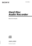
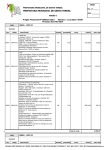
TC-EX66 SERVICE MANUAL AEP Model UK Model E Model This set is the cassette deck section in MHC-EX66. Dolby noise reduction manufactured under license from Dolby Laboratories Licensing Corporation. “DOLBY” and the double-D symbol a are trademarks of Dolby Laboratories Licensing Corporation. Model Name Using Similar Mechanism Tape Transport Mechanism Type NEW TCM-ACLM578 SPECIFICATIONS STEREO CASSETTE DECK MICROFILM SERVICING NOTES TABLE OF CONTENTS How to operate with a single unit. Servicing Notes ............................................................... 2 1. GENERAL Playing a Tape ................................................................ Recording on a Tape Manually ....................................... Recording the favorite CD Tracks on a Tape .................. 3 4 5 2. DISASSEMBLY ........................................................ 6 3. MECHANICAL ADJUSTMENTS ...................... 10 4. ELECTRICAL ADJUSTMENTS ........................ 10 5. DIAGRAMS Normally, this set is not operated with its own. The exclusive jig (J-2501-078-A) and service box (PFJ-1) are necessary to operate the set with a single unit. Turn the power set of the service box ON. Then press the ENTER/NEXT button and SLEEP button at the same time to turn the power on. Connection: SERVICE BOX (PFJ-1) POWER SW 5-1. Printed Wiring Boards .................................................... 15 5-2. Schematic Diagram ........................................................ 19 5-3. IC Pin Function .............................................................. 25 6. EXPLODED VIEWS ............................................... 27 7. ELECTRICAL PARTS LIST ............................... 32 FH-E939, 838,937 CDP/TC JIG (J-2501-078-A) CN904 17P CN902 7P SET CN101 7P SYSTEM CONTROL CORD WITH CONNECTOR 17P CORD WITH CONNECTOR 7P (attached to PFJ-1) (attached to set) • KEY/FL tube/LED check mode. To enter KEY/FL tube/LED check mode, press the ENTER/NEXT and REC buttons at the same time. Under mode, every time when press any key or turn MULTI CONTROLLER knob, change to next situation. 1 2 3 4 5 All LED indicators light on All FL tube indicators light on A part of FL tube light on mode 1. (Indicated ST-SEG) A part of FL tube light on mode 2. (Indicated RDS-SEG) KEY check mode Note: 1) All LED light on mode is kept, when buttons which is pressed to enter all LED light on mode, release same time. When release them separate timing, it is moved to next All LED light on mode. 2) After all LED light on mode, light on point remove one by one, when any button pressed or MULTI CONTROLLER knob turned. 3) Under KEY check mode, every time buttons pressed numerical value of “KEY” in FL tube increase. And that time, numerical value of “ECDR” increase when MULTI CONTROLLER button turn to + direction, and it decrease turn to – direction. When you want to finish this mode, unplug the power of amplifier or turn off PFJ-1 of POWER switch. –2– SECTION 1 GENERAL –3– This section is extracted from instruction manual. –4– –5– SECTION 2 DISASSEMBLY • This set can be disassembled in the order shown below. CASE, FRONT PANEL (Page 6) MECHANISM DECK (Page 7) MECHANISM CHASSIS SECTION (Page 8) MAIN BOARD (Page 7) TRY ASS’Y (Page 8) CAPSTAN MOTOR (Page 9) Note: Follow the disassembly procedure in the numerical order given. CASE, FRONT PANEL 2 case 1 two screws (case 3 TP 2) 8 lid (R-TC) 1 two screws (case TP2) 4 flat cable (27 core) (CN802) 3 flat cable (5 core) (CN301) 7 front panel 6 three claws 5 two screws (BVTP 3 × 8) 5 screw (BVTP3 × 8) –6– MECHANISM DECK 2 four screws (BVTP3 × 8) 1 two connectors (CN803, 804) 3 mechanism deck 1 connector (CN351) 2 three connectors (CN351, 803, 804) MAIN BOARD 3 two screws (BVTP3 × 8) 6 main board 1 Slide the tray to deviation of the arrow A. 4 two screws (BVTP3 × 10) A 5 two PCB holders –7– TRAY ASS’Y 1 screw (M1.7 × 8.2) 4 arm 576 5 tray ass’y 2 tension spring 3 boss MECHANISM CHASSIS SECTION 3 mechanism chassis section 1 four screws (BK3 × 6) 2 screw (P3 × 8) –8– CAPSTAN MOTOTR 7 capstan motor 2 two claws 5 Hang the belt. 2 two claws 6 three motor screws. 3 control board 4 Remove the solder of motor lead wire. 1 step screw –9– SECTION 3 MECHANICAL ADJUSTMENTS SECTION 4 ELECTRICAL ADJUSTMENTS PRECAUTION 1. Clean the following parts with a denatured-alcohol-moistened swab: record/playback/earth head pinch roller rubber belts capstan idlers 2. Demagnetize the record/playback head with a head demagnetizer. (Do not bring the head demagnetizer close to the erase head.) 3. Do not use a magnetized screwdriver for the adjustments. 4. After the adjustments, apply suitable locking compound to the parts adjusted. 5. The adjustments should be performed with the rated power supply voltage unless otherwise noted. PRECAUTION 1. The adjustment should be performed in the publication. (Be sure to male playback adjustment at first.) 2. The adjustments and measurement should be performed for both L-CH and R-CH. • Switch position DOLBY NR switch : OFF DIRECTION switch :A • Standard record position Deliver the standard input signal level to input jack and set the REC LEVEL (RV301) control to obtain the standard output signal level as follows. Torque Measurement Mode Torque Meter FWD FWD Back tension CQ-102C REV REV Back tension FF, REW CQ-102RC CQ-201B – Record Mode – AF OSC Meter Reading attenuator 30-65 g•cm (0.42-0.90 oz•inch) level meter 10 k Ω 47 k Ω 600 Ω LINE IN 1.5-6 g•cm (0.021-0.083 oz•inch) + – set LINE OUT 30-65 g•cm (0.42-0.90 oz•inch) 1.5-6 g•cm (0.021-0.083 oz•inch) Standard Input Level Input terminal 70-130 g•cm (0.98-1.80 oz•inch) LINE IN source impedance 10 kΩ input signal level 0.5 V (– 3.8 dB) Standard Output Level Output terminal LINE OUT (L-CH) load impedance 47 kΩ output signal level 0.5 V (– 3.8 dB) Test Tape Type Signal P-4-A100 10 kHz, – 10 dB Azimuth Adjustment Used for P-4-L300 315 Hz, 0 dB PB Level Adjustment WS-48B 3 kHz, 0 dB Tape Speed Adjustment 0 dB = 0.775 V Test Mode With the POWER turned OFF, short the test point CN801 (2P) on the MAIN board (making IC801 pin &¢ “L”) and turn the POWER ON. Thus, the TEST mode will be activated. If a recording is done in the TEST mode, the REC MEMORY mode becomes active where the tape is rewound by the amount of recording when a rewinding is executed after recording. After adjustment, make the CN801 (2P) open to release the TEST mode. – 10 – Tape Speed Adjustment Procedure: Mode: FWD playback Record/Playback Head Azimuth Adjustment Procedure: 1. Mode: REV playback test tape P-4-A100 (10 kHz, – 10 dB) test tape WS-48B (3 kHz, 0 dB) level meter 47 k Ω 47 k Ω + – set LINE OUT 2. Turn the adjustment screw for the maximum output levels. If these levels do not match, turn the adjustment screw until both of output levels match together within 1 dB. within 1dB R-CH peak 1. Set to FWD playback mode. 2. Adjust Variable resistor on the motor (M902) so that the frequency counter reading becomes 3,000 ± 90 Hz. 3. Confirm that the deviation between tape top and tape end is within 3%. Adjustment Location: CAPSTAN/REEL motor (M902) within 1dB output level Screw position + – set LINE OUT L-CH peak frequency counter angle L-CH peak R-CH peak 3. Phase Check Mode: REV playback test tape P-4-A100 (10 kHz, –10 dB) M902 oscilloscope L-CH 47 k Ω set 47 k Ω V + – + – H R-CH LINE OUT Screen pattern in phase 45° 90° 135° Good adjustable resistor Sample Value of Wow and flutter: 0.3% or less W. RMS (WS-48B) 180° Wrong 4. Set in the FWD mode and repeat the step 1 to 3. 5. After the adjustment, lock the screw with locking compound. Adjustment Location: Record/Playback head FWD side REV side Adjustment screw – 11 – Playback Level Adjustment Procedure: Mode: FWD playback Record Level Adjustment Setting: REC LEVEL control: Standard record position (See page 10) set to the TEST mode (REC MEMRY mode) (See page 10) test tape P-4-L300 (315 Hz, 0 dB) level meter Procedure: 1. Mode :Record 47 k Ω + – set AF OSC LINE OUT attenuator Adjust RV151 (L-CH) and RV251 (R-CH) so that the reading on level meter meets the adjustment limits below. 600 Ω Adjustment Limits: LINE OUT level: – 7.7 ± 0.5 dB (0.301 to 0.338 V) Level difference between channels: within 2 dB Check that the LINE OUT level does not change even if Playback and Stop operation is repeated several times. blank tape CS-123 10 k Ω set LINE IN 315 Hz, 50 mV (– 23.8 dB) 2. Mode: Playback level meter recorded portion 47 k Ω Adjustment Location: MAIN board (See page 13) AF OSC attenuator 600 Ω LINE OUT blank tape CS-123 10 k Ω 3. Confirm playback the signal recorded in step 1 become adjustment level as follows. 4. If these levels do not adjustment level, adjust RV153 (L-CH) and RV253 (R-CH) to repeat step 1 and 2. Adjustment Level: – 23.8 ± 0.5 dB (47 to 53 mV) Adjustment Location: MAIN board (See page 13) set LINE IN 1) 315 Hz 50 mV (– 23.8 dB) 2) 10 kHz 2. Mode: Playback level meter recorded portion 47 k Ω + – set + – set Record BIAS Adjustment Setting: REC LEVEL control: Standard record position (See page 10) Set to the TEST mode (REC MEMRY mode) (See page 10) Procedure: 1. Mode: Record LINE OUT 3. Confirm playback the signal recorded in step 1 become adjustment level as follows. 4. If these levels do not adjustment level, adjust the RV152 (LCH) and RV252 (R-CH) to repeat step 1 and 2. Adjustment Level: Playback output of 10 kHz to playback output of 315 Hz: ± 0.5 dB. Adjustment Location: MAIN board (See page 13) – 12 – • Adjustment Parts Location RV251 Playback Level (R-CH) RV151 Playback Level (L-CH) [MAIN BOARD] (Component Side) CN11 CN801 TEST Mode J301 RV152 Record BIAS (L-CH) RV252 Record BIAS (R-CH) – 13 – RV153 Record Level (L-CH) RV253 Record Level (R-CH) SECTION 5 DIAGRAMS • IC Block Diagrams IC304 CXA1198AP GP GL GH I REF VCC IN (R) 16 15 14 13 12 11 GND (R) OUT (R) 10 9 EQ CONTROL EQ 1 2 3 4 5 6 7 8 f/Q fQ fM REF GND VEE IN (L) GND (L) OUT (L) IC804 LB1641 T.S.D O.C.P MOTOR DRIVE MOTOR DRIVE 8 9 10 VCC 2 NOISE FILTER MOTOR DRIVE 6 7 VCC 1 5 REV.IN 4 FWD.IN MOTOR DRIVE LA5617 ON/OFF CURRENT LIMITER CURRENT LIMITER VMUTE VCC VREF VCC ERROR AMP ON/OFF ~_140uA COMPARATER IC805 3 CLAMP 2 NOISE FILTER 1 GND FWD/REV/STOP CONTROL LOGIC START CIRCUIT VREF OVER HEAT PROTECT VREF _1.8V ~ 1 2 3 4 5 6 7 8 9 10 VO1 VCC CN1 EN EN DISPLAY GND NC CN2 VEE VO2 ERROR AMP – 14 – 5-3. IC PIN FUNCTION DESCRIPTION • MAIN BOARD IC801 HD6433724E66F (SYSTEM CONTROL) Pin No. Pin Name I/O 1 PULSE I Pulse signal input Function 2 NO-USE – Not used (Fixed at “L”) 3 METER-L I Digital peak level meter signal input (L-ch) 4 METER-R I Digital peak level meter signal input (R-ch) 5 AD-GND – Ground for A/D converter 6 TEST I Not used (Fixed at “L”) 7 NO-USE – Not-used (Open) 8 NO-USE – Not-used (Fixed at “L”) 9 SYS-GND – Ground for system 10 OSC-OUT O System clock output (4 MHz) 11 OSC-IN I System clock input (4 MHz) 12 RESET I Reset signal input 13 AUB-IN I Audio bus input 14 AUB-OUT O Audio bus output 15 NO-USE – Not used (Fixed at “L”) 16 NO-USE – Not used (Fixed at “L”) 17 NO-USE – Not used (Fixed at “L”) 18 NO-USE – Not used (Fixed at “L”) 19 NO-USE – Not used (Fixed at “L”) 20 DOLBY C/B O DOLBY B/C select signal output “L”: DOLBY B, “H”: DOLBY C 21 DOLBY ON/OFF O DOLBY on/off select signal output “L”: DOLBY off, “H”: DOLBY on 22 CDSYNC-LED O Control output to CD SYNC LED (D851) 23 SEG17 O Segment signal output to fluorescent indicator tube (FLT851) 24 SEG16 O Segment signal output to fluorescent indicator tube (FLT851) 25 SEG15 O Segment signal output to fluorescent indicator tube (FLT851) 26 SEG14 O Segment signal output to fluorescent indicator tube (FLT851) 27 SEG13 O Segment signal output to fluorescent indicator tube (FLT851) 28 SEG12 O Segment signal output to fluorescent indicator tube (FLT851) 29 SEG11 O Segment signal output to fluorescent indicator tube (FLT851) 30 SEG10 O Segment signal output to fluorescent indicator tube (FLT851) 31 SEG9 O Segment signal output to fluorescent indicator tube (FLT851) 32 SEG8 O Segment signal output to fluorescent indicator tube (FLT851) 33 SEG7 O Segment signal output to fluorescent indicator tube (FLT851) 34 SEG6 O Segment signal output to fluorescent indicator tube (FLT851) 35 SEG5 O Segment signal output to fluorescent indicator tube (FLT851) 36 SEG4 O Segment signal output to fluorescent indicator tube (FLT851) 37 SEG3 O Segment signal output to fluorescent indicator tube (FLT851) 38 SEG2 O Segment signal output to fluorescent indicator tube (FLT851) 39 SEG1 O Segment signal output to fluorescent indicator tube (FLT851) 40 FL-GND I Ground for fluorescent indicator tube (Fixed at “L” (–20 V)) 41 GRID 1 O Grid signal output to fluorescent indicator tube (FLT851) 42 GRID 2 O Grid signal output to fluorescent indicator tube (FLT851) 43 GRID 3 O Grid signal output to fluorescent indicator tube (FLT851) 44 GRID 4 O Grid signal output to fluorescent indicator tube (FLT851) 45 GRID 5 O Grid signal output to fluorescent indicator tube (FLT851) – 25 – Pin No. Pin Name I/O Function 46 NO-USE – Not used (Open) 47 NO-USE – Not used (Open) 48 NO-USE – Not used (Open) 49 TYPE IV O Tape type output “H”: Metal Position 50 TYPE II O Tape type output “H”: High position 51 TYPE I O Tape type output “H”: Normal position 52 REC MUTE O Recording mute on/off control output “H”: Mute on 53 RELAY O Relay drive output “H”: On 54 NC – Not used (Open) 55 REC/PB O Mode control output to DOLBY NR amplifier (IC301) “L”: Record 56 PB MUTE O Playback mute on/off control output “H”: Mute on 57 SYS-VCC I Power supply for system 58 OPTION O Not used (Fixed at “L”) 59 NO-USE – Not used (Fixed at “L”) 60 POWER-OUT O Audio and mechanism power on/off output “H”: On 61 BIAS O Control output to recording bias switch (Q352) “L”: On 62 POW-IN I Primary power on/off input “H”: On 63 CLOSE SW I Close detection input from S901 “L”: Close 64 OPEN-SW I Open detection input from S902 “L”: Open 65 SOLENOIDE O Plunger (PMxxx) drive output “H”: On 66 LINE-MUTE O Line mute on/off control output “L”: Mute on 67 CHORM-SW I Tape type detection input from Sxxx “L”: Type I 68 METAL-SW I Tape type detection input from Sxxx “L”: Type IV 69 REC-REV-SW I Record proof detection input from Sxxx (REV side) “H”: Not nail 70 REC-FW-SW I Record proof detection input from Sxxx (FWD side) “H”: Not nail 71 CAPSTAN O Capstan/reel motor (M902) drive output “H”: On 72 CLOSE O Loading motor (M901) drive output *1 73 OPEN O Loading motor (M901) drive output *1 74 TEST I Test mode terminal 75 MODE-SW I Head sensor input from Sxxx 76 AD-VCC I Power supply for A/D converter 77 KEY 1 I Key input (A/D convert input)*2 78 KEY 2 I Key input (A/D convert input)*2 79 HALF-SW I Cassette half detection input from Sxxx 80 AMS-IN I AMS input *1 Loading Motor (M901) IN OUT BRAKE CLOSE &™ H L H OPEN &£ L H H Voltage Input port 0V 0.45 V 1.19 V 2.19 V 3.2 V 3.98 V 4.48 V 5.0 V Pin &•, KEY 2 Open/Close § STOP p PAUSE P FWD · REV ª CD SYNC — Not key input Pin &¶, KEY 1 POWER ON/OFF REW 0 FF ) REC r RESET *2 Key Input – 26 – DIRECTION DOLBY NR Not key input SECTION 6 EXPLODED VIEWS NOTE: • -XX and -X mean standardized parts, so they may have some difference from the original one. • Color Indication of Appearance Parts Example: KNOB, BALANCE (WHITE) . . . (RED) ↑ ↑ Parts Color Cabinet's Color • Items marked “*” are not stocked since they are seldom required for routine service. Some delay should be anticipated when ordering these items. • The mechanical parts with no reference number in the exploded views are not supplied. • Hardware (# mark) list is given in the last of the electrical parts list. (1) CASE, FRONT PANEL SECTION 16 14 15 13 6 7 5 15 not supplied not supplied not supplied 12 7 4 3 11 10 8 9 #1 2 #1 1 Ref. No. Ref. No. Part No. Description KNOB PANEL ASSY, FRONT EMBLEM (4-A), SONY WINDOW (TC) BUTTON (REC) (CD SYNC, r REC) 9 10 * 11 12 13 3-939-642-01 3-939-643-01 A-2007-722-A 1-782-490-11 1-773-257-11 BUTTON (PLAY) (ª, ·, p) BUTTON (FF) (0, )) PANEL BOARD, COMPLETE WIRE (FLAT TYPE) (5 CORE) WIRE (FLAT TYPE) (27 CORE) 3-939-647-01 INDICATOR (TC) 4-951-620-01 SCREW (2.6X8), +BVTP 3-012-560-01 BUTTON (EJECT) (§ OPEN/CLOSE) 14 15 * 16 3-012-561-01 LID (R-TC) 3-363-099-01 SCREW (CASE 3 TP2) 3-939-652-11 CASE Part No. Description 1 2 3 4 5 4-985-926-01 X-3373-604-1 4-962-708-01 3-939-648-01 3-939-646-01 6 7 8 Remark – 27 – Remark (2) CHASSIS SECTION #1 TCM-ACLM578 55 #1 #2 #2 #2 not supplied 53 54 #2 52 51 not supplied Ref. No. Part No. Description 51 52 * 53 4-977-699-11 LEG (F) 4-965-822-01 FOOT 3-350-847-31 HOLDER, PCB Remark Ref. No. Part No. * 54 * 55 A-2007-721-A MAIN BOARD, COMPLETE 3-012-563-02 PANEL, BACK – 28 – Description Remark (3) MECHANISM DECK SECTION-1 (TCM-ACLM578) 109 108 110 111 106 #5 107 119 118 120 122 #4 118 105 M901 121 #6 S901 #7 112 117 #6 S902 116 116 #3 104 115 #3 113 114 103 102 #8 #9 101 Ref. No. Part No. Description 101 102 103 104 105 3-017-214-01 3-017-215-01 3-017-233-01 3-017-216-01 3-017-213-01 HOLDER ARM (A) RACK, GEAR ARM (C) CHASSIS 106 107 108 109 110 3-017-212-01 3-017-235-01 3-017-244-01 3-017-217-01 3-017-218-01 TRAY SPRING (A) SCREW (1.7X8.2), SPECIAL ARM (576) RETAINER 111 112 113 3-017-219-01 PLATE 3-017-211-01 FRAME 3-017-236-01 SPRING (B) Remark Ref. No. Part No. Description 114 115 116 117 118 3-017-234-01 3-017-243-01 3-017-242-01 3-017-232-01 3-017-241-01 GROUND, PLATE NUT BUFFER GEAR (B) WASHER (1.6X4X0.5) 119 120 121 122 M901 3-017-237-01 3-017-231-01 3-017-220-01 3-017-240-01 3-017-239-01 BELT (49.2) PULLEY (C) ARM WASHER (2.1X4X0.5) PULLEY (MOTOR) (LOADING) S901 S902 3-017-238-01 LIMITTER (SW MSS-8B) (OPEN) 3-017-238-01 LIMITTER (SW MSS-8B) (CLOSE) – 29 – Remark (4) MECHANISM DECK SECTION-2 (TCM-ACLM578) 155 158 157 HRPE901 M902 155 161 not supplied 156 159 155 154 155 162 not supplied 153 A 160 not supplied A 163 165 164 155 152 166 not supplied 151 Ref. No. Part No. 151 * 152 153 154 155 3-017-294-01 SCREW (S), SPECIAL CONTROL BOARD 3-017-273-01 LEVER AC, SPRING 3-017-270-01 AC, LEVER 3-017-279-01 SCREW (M2), SPECIAL 160 161 162 163 164 3-017-274-01 3-017-254-01 3-017-253-01 3-017-277-01 165 3-017-280-01 166 3-017-285-01 HRPE901 M902 3-017-259-01 156 157 158 159 Description HEAD, SPRING BASE PINCH ROLLER (F) CHASSIS (HEAD) PINCH (F), SPRING Remark Ref. No. – 30 – Part No. Description 3-017-278-01 3-017-300-01 3-017-255-01 3-017-296-01 3-017-297-01 PINCH (R), SPRING WASHER, FLAT PINCH ROLLER (R) CUTION (MOTOR) SCREW (MOTOR) Remark SCREW (M2 TAPPING), SPECIAL BELT (MAIN) HEAD ASSY (RECORD/PLAYBACK/ERASE) PULLEY (MOTOR) (CAPSTAN/REEL) (5) MECHANISM DECK SECTION-3 (TCM-ACLM578) 216 214 217 214 213 218 213 212 219 221 215 211 211 220 222 223 210 224 209 225 224 208 209 203 208 207 226 204 205 227 206 202 201 Ref. No. Part No. Description 215 216 217 218 219 3-017-272-01 3-017-281-01 3-017-256-01 3-017-275-01 3-017-267-01 SPRING (BT) (R) WASHER, FLAT ARM (PLAY) LOCK, SPRING CAM LOCK, ARM CAM 3-017-283-01 WASHER, FLAT CLUTCH ASSY 3-017-263-01 REEL, BASE 3-017-295-01 WASHER, FLAT 3-017-252-01 CHASSIS (OS) 220 221 222 223 224 3-017-282-01 3-017-264-01 3-017-266-01 3-017-268-01 3-017-269-01 WASHER, FLAT CAM, GEAR BASE, LEVER ARM (RF) GEAR (RF) 3-017-298-01 3-017-299-01 3-017-288-01 3-017-262-01 225 226 227 3-017-276-01 ARM (RF), SPRING 3-017-293-01 MAGNET, PLATE 3-017-271-01 CAP (MG) Part No. Description 201 202 203 204 205 3-017-258-01 3-017-257-01 3-017-284-01 3-017-265-01 FLYWHEEL (R) FLYWHEEL (F) BELT (SUB) IDLER, GEAR GEAR P ASSY 206 207 208 209 210 211 212 213 214 WASHER (B/T) SPRING (B/T) (F) REEL, CAP REEL, BUSHING Remark Ref. No. – 31 – Remark CONTROL SECTION 7 ELECTRICAL PARTS LIST MAIN NOTE: • Due to standardization, replacements in the parts list may be different from the parts specified in the diagrams or the components used on the set. • -XX and -X mean standardized parts, so they may have some difference from the original one. • RESISTORS All resistors are in ohms. METAL: Metal-film resistor. METAL OXIDE: Metal oxide-film resistor. F: nonflammable Ref. No. Part No. • Items marked “*” are not stocked since they are seldom required for routine service. Some delay should be anticipated when ordering these items. • SEMICONDUCTORS In each case, u: µ, for example: uA. . : µA. . uPA. . : µPA. . uPB. . : µPB. . uPC. . : µPC. . uPD. . : µPD. . • CAPACITORS uF: µF • COILS uH: µH Description Remark Description Remark 1-162-306-11 CERAMIC 1-162-306-11 CERAMIC 0.01uF 0.01uF 20% 16V 20% 16V C131 C132 C151 C152 C153 1-162-290-31 1-162-282-31 1-130-467-00 1-137-372-11 1-107-714-11 CERAMIC CERAMIC MYLAR FILM ELECT 470PF 100PF 470PF 0.022uF 10uF 10% 10% 5% 5% 20% 50V 50V 50V 50V 16V C154 C155 C156 C157 C158 1-107-610-11 1-107-609-11 1-102-820-00 1-126-964-11 1-126-960-11 CERAMIC CERAMIC CERAMIC ELECT ELECT 82PF 75PF 330PF 10uF 1uF 5% 5% 5% 20% 20% 500V 500V 50V 50V 50V C159 C160 C161 C162 C163 1-126-964-11 1-162-282-31 1-128-563-11 1-128-563-11 1-126-935-11 ELECT CERAMIC ELECT ELECT ELECT 10uF 100PF 100uF 100uF 470uF 20% 10% 20% 20% 20% 50V 50V 100V 100V 16V < SWITCH > C164 C191 C201 C202 C203 1-126-935-11 1-162-282-31 1-126-963-11 1-137-372-11 1-126-964-11 ELECT CERAMIC ELECT FILM ELECT 470uF 100PF 4.7uF 0.022uF 10uF 20% 10% 20% 5% 20% 16V 50V 50V 50V 50V SWITCH, DETECT (FWD REC DET) SWITCH, DETECT (HALF DET) SWITCH, DETECT (Cr02 DET) SWITCH, DETECT (METAL DET) SWITCH, DETECT (REV REC DET) C204 C205 C206 C207 C211 1-136-165-00 1-136-163-00 1-126-964-11 1-126-961-11 1-126-960-11 FILM FILM ELECT ELECT ELECT 0.1uF 0.068uF 10uF 2.2uF 1uF 5% 5% 20% 20% 20% 50V 50V 50V 50V 50V C231 C232 C251 C252 C253 1-162-290-31 1-162-282-31 1-130-467-00 1-137-372-11 1-107-714-11 CERAMIC CERAMIC MYLAR FILM ELECT 470PF 100PF 470PF 0.022uF 10uF 10% 10% 5% 5% 20% 50V 50V 50V 50V 16V C254 C255 C256 C257 C258 1-107-610-11 1-107-609-11 1-102-820-00 1-126-964-11 1-126-960-11 CERAMIC CERAMIC CERAMIC ELECT ELECT 82PF 75PF 330PF 10uF 1uF 5% 5% 5% 20% 20% 500V 500V 50V 50V 50V C259 C260 C291 C301 C302 1-126-964-11 1-162-282-31 1-162-282-31 1-126-964-11 1-126-964-11 ELECT CERAMIC CERAMIC ELECT ELECT 10uF 100PF 100PF 10uF 10uF 20% 10% 10% 20% 20% 50V 50V 50V 50V 50V C303 C304 1-162-282-31 CERAMIC 1-161-494-00 CERAMIC 100PF 0.022uF 10% 50V 25V < CONNECTOR > CN Part No. C121 C122 CONTROL BOARD *************** * Ref. No. When indicating parts by reference number, please include the board. 3-017-287-01 TERMINAL (RP) < DIODE > D D 8-719-987-63 DIODE 1N418M 8-719-987-63 DIODE 1N418M < IC > IC 3-017-289-01 PLATE, ROTARY DETECTION < PLUNGER SOLENOID > PM 3-017-292-01 SOLENOID < RESISTOR > R S S S S S 1-247-682-11 CARBBBON 3-017-290-01 3-017-290-01 3-017-290-01 3-017-290-01 3-017-290-01 S 3-017-291-01 SWITCH, MODE (MODE) ************************************************************* * A-2007-721-A MAIN BOARD, COMPLETE ******************** * 3-309-144-21 HEAT SINK 7-685-871-01 SCREW +BVTT 3X6 (S) < CAPACITOR > C101 C102 C103 C104 C105 1-126-963-11 1-137-372-11 1-126-964-11 1-136-165-00 1-136-163-00 ELECT FILM ELECT FILM FILM C106 C107 C111 1-126-964-11 ELECT 1-126-961-11 ELECT 1-126-960-11 ELECT 4.7uF 0.022uF 10uF 0.1uF 0.068uF 20% 5% 20% 5% 5% 50V 50V 50V 50V 50V 10uF 2.2uF 1uF 20% 50V 20% 50V 20% 50V – 32 – MAIN Ref. No. Part No. Description Remark Part No. Description 1-564-715-11 PIN, CONNECTOR (SMALL TYPE)13P C305 C306 C307 1-162-217-31 CERAMIC 1-126-961-11 ELECT 1-126-961-11 ELECT 56PF 2.2uF 2.2uF 5% 50V 20% 50V 20% 50V * CN804 C310 C311 C312 C313 C314 1-162-306-11 1-162-306-11 1-164-159-11 1-164-159-11 1-162-294-31 CERAMIC CERAMIC CERAMIC CERAMIC CERAMIC 0.01uF 0.01uF 0.1uF 0.1uF 0.001uF 20% 16V 20% 16V 50V 50V 10% 50V D101 D102 D201 D202 D301 8-719-987-63 8-719-987-63 8-719-987-63 8-719-987-63 8-719-987-63 DIODE DIODE DIODE DIODE DIODE 1N4148M 1N4148M 1N4148M 1N4148M 1N4148M C315 C351 C352 C353 C354 1-162-294-31 1-126-925-11 1-126-925-11 1-126-961-11 1-126-933-11 CERAMIC ELECT ELECT ELECT ELECT 0.001uF 470uF 470uF 2.2uF 100uF 10% 20% 20% 20% 20% 50V 10V 10V 50V 16V D302 D303 D351 D352 D353 8-719-987-63 8-719-987-63 8-719-987-63 8-719-987-63 8-719-987-63 DIODE DIODE DIODE DIODE DIODE 1N4148M 1N4148M 1N4148M 1N4148M 1N4148M C355 C356 C357 C358 C360 1-126-960-11 1-137-370-11 1-137-436-11 1-137-436-11 1-126-961-11 ELECT FILM FILM FILM ELECT 1uF 0.01uF 0.0039uF 0.0039uF 2.2uF 20% 5% 5% 5% 20% 50V 50V 50V 50V 50V D354 D355 D356 D702 D704 8-719-987-63 8-719-200-82 8-719-200-82 8-719-200-82 8-719-200-82 DIODE DIODE DIODE DIODE DIODE 1N4148M 11ES2 11ES2 11ES2 11ES2 C361 C701 C702 C703 C705 1-136-562-11 1-126-943-11 1-126-943-11 1-126-960-11 1-126-943-11 FILM ELECT ELECT ELECT ELECT 0.0082uF 2200uF 2200uF 1uF 2200uF 5% 20% 20% 20% 20% 630V 25V 25V 50V 25V D705 D706 D715 D716 D717 8-719-987-63 8-719-987-63 8-719-933-33 8-719-200-82 8-719-200-82 DIODE DIODE DIODE DIODE DIODE 1N4148M 1N4148M HZS6A1L 11ES2 11ES2 C719 C721 C722 C801 C802 1-126-916-11 1-104-664-11 1-164-159-11 1-126-964-11 1-161-494-00 ELECT ELECT CERAMIC ELECT CERAMIC 1000uF 47uF 0.1uF 10uF 0.022uF 20% 6.3V 20% 25V 50V 20% 50V 25V D718 D719 D801 D802 D803 8-719-200-82 8-719-200-82 8-719-933-33 8-719-933-33 8-719-987-63 DIODE DIODE DIODE DIODE DIODE 11ES2 11ES2 HZS6A1L HZS6A1L 1N4148M C803 C804 C805 C806 C807 1-161-494-00 1-162-294-31 1-126-916-11 1-126-963-11 1-162-306-11 CERAMIC CERAMIC ELECT ELECT CERAMIC 0.022uF 0.001uF 1000uF 4.7uF 0.01uF 10% 20% 20% 20% 25V 50V 6.3V 50V 16V D804 D805 D806 D807 D808 8-719-987-63 8-719-987-63 8-719-933-33 8-719-987-63 8-719-933-48 DIODE DIODE DIODE DIODE DIODE 1N4148M 1N4148M HZS6A1L 1N4148M HZS7B3L C808 C809 C810 C811 C812 1-126-935-11 1-164-159-11 1-164-159-11 1-162-282-31 1-126-964-11 ELECT CERAMIC CERAMIC CERAMIC ELECT 470uF 0.1uF 0.1uF 100PF 10uF 20% 16V 50V 50V 10% 50V 20% 50V D809 D810 D811 D812 D813 8-719-987-63 8-719-987-63 8-719-210-21 8-719-200-82 8-719-200-82 DIODE DIODE DIODE DIODE DIODE 1N4148M 1N4148M 11EQS04 11ES2 11ES2 C813 C814 C815 C816 C817 1-164-159-11 1-162-306-11 1-126-933-11 1-126-933-11 1-164-159-11 CERAMIC CERAMIC ELECT ELECT CERAMIC 0.1uF 0.01uF 100uF 100uF 0.1uF 50V 20% 16V 20% 10V 20% 10V 50V D814 D815 D816 D817 D818 8-719-200-82 8-719-200-82 8-719-200-82 8-719-200-82 8-719-200-82 DIODE DIODE DIODE DIODE DIODE 11ES2 11ES2 11ES2 11ES2 11ES2 C819 C820 C821 C822 C823 1-126-969-11 1-126-969-11 1-126-969-11 1-126-969-11 1-162-306-11 ELECT ELECT ELECT ELECT CERAMIC 220uF 220uF 220uF 220uF 0.01uF 20% 20% 20% 20% 20% D820 8-719-002-09 DIODE UZL-18M C824 1-162-306-11 CERAMIC 0.01uF 20% 16V < DIODE > 50V 50V 50V 50V 16V < GROUND TERMINAL > EPT01 CN11 CN301 CN351 CN801 CN802 * CN803 1-770-158-21 HOUSING, CONNECTOR 7P (SYSTEM CONTROL) 1-568-824-11 SOCKET, CONNECTOR 5P 1-564-707-11 PIN, CONNECTOR (SMALL TYPE) 5P 1-564-704-11 PIN, CONNECTOR (SMALL TYPE) 2P 1-568-842-11 SOCKET, CONNECTOR 27P 1-564-708-11 PIN, CONNECTOR (SMALL TYPE) 6P 1-537-770-21 TERMINAL BOARD, GROUND < IC > < CONNECTOR > * * * * Ref. No. IC301 IC302 IC303 IC304 IC305 8-752-060-46 8-759-634-51 8-759-634-51 8-752-060-64 8-759-710-59 IC IC IC IC IC CXA1561S M5218AP M5218AP CXA1198AP NJM4580D-D IC306 IC703 IC801 IC802 8-759-634-51 8-759-604-35 8-759-479-87 8-759-165-85 IC IC IC IC M5218AP M5F78M05L HD6433724E66F PST600H-T – 33 – Remark MAIN Ref. No. Part No. Description IC804 8-759-822-09 IC LB1641 IC805 8-759-288-53 IC LA5617 Remark Ref. No. Part No. Description Remark R21 R22 R23 R24 1-247-870-11 1-249-438-11 1-247-884-11 1-247-872-11 CARBON CARBON CARBON CARBON 43K 56K 160K 51K 5% 5% 5% 5% 1/4W 1/4W 1/4W 1/4W R25 R26 R41 R42 R43 1-247-883-00 1-247-887-00 1-249-438-11 1-247-876-11 1-249-439-11 CARBON CARBON CARBON CARBON CARBON 150K 220K 56K 75K 68K 5% 5% 5% 5% 5% 1/4W 1/4W 1/4W 1/4W 1/4W R44 R45 R46 R101 R102 1-247-876-11 1-247-876-11 1-249-441-11 1-249-441-11 1-249-441-11 CARBON CARBON CARBON CARBON CARBON 75K 75K 100K 100K 100K 5% 5% 5% 5% 5% 1/4W 1/4W 1/4W 1/4W 1/4W R103 R104 R105 R106 R107 1-249-429-11 1-249-421-11 1-247-843-11 1-247-843-11 1-249-428-11 CARBON CARBON CARBON CARBON CARBON 10K 2.2K 3.3K 3.3K 8.2K 5% 5% 5% 5% 5% 1/4W 1/4W 1/4W 1/4W 1/4W R108 R109 R110 R111 R112 1-249-417-11 1-249-418-11 1-249-433-11 1-249-417-11 1-247-866-11 CARBON CARBON CARBON CARBON CARBON 1K 1.2K 22K 1K 30K 5% 5% 5% 5% 5% 1/4W 1/4W 1/4W 1/4W 1/4W R113 R114 R115 R117 R118 1-249-439-11 1-249-410-11 1-249-429-11 1-249-441-11 1-249-441-11 CARBON CARBON CARBON CARBON CARBON 68K 270 10K 100K 100K 5% 5% 5% 5% 5% 1/4W 1/4W 1/4W 1/4W 1/4W R121 R133 R134 R135 R151 1-249-429-11 1-249-429-11 1-249-429-11 1-249-429-11 1-247-881-00 CARBON CARBON CARBON CARBON CARBON 10K 10K 10K 10K 120K 5% 5% 5% 5% 5% 1/4W 1/4W 1/4W 1/4W 1/4W R152 R153 R154 R155 R156 1-249-404-00 1-247-882-11 1-247-850-11 1-249-430-11 1-249-426-11 CARBON CARBON CARBON CARBON CARBON 82 130K 6.2K 12K 5.6K 5% 5% 5% 5% 5% 1/4W 1/4W 1/4W 1/4W 1/4W R157 R158 R159 R160 R162 1-249-421-11 1-247-843-11 1-249-429-11 1-249-421-11 1-249-413-11 CARBON CARBON CARBON CARBON CARBON 2.2K 3.3K 10K 2.2K 470 5% 5% 5% 5% 5% 1/4W 1/4W 1/4W 1/4W 1/4W R163 R201 R202 R203 R204 1-249-413-11 1-249-441-11 1-249-441-11 1-249-429-11 1-249-421-11 CARBON CARBON CARBON CARBON CARBON 470 100K 100K 10K 2.2K 5% 5% 5% 5% 5% 1/4W 1/4W 1/4W 1/4W 1/4W R205 R206 R207 R208 R209 1-247-843-11 1-247-843-11 1-249-428-11 1-249-417-11 1-249-418-11 CARBON CARBON CARBON CARBON CARBON 3.3K 3.3K 8.2K 1K 1.2K 5% 5% 5% 5% 5% 1/4W 1/4W 1/4W 1/4W 1/4W R210 R211 R212 R213 R214 1-249-433-11 1-249-417-11 1-247-866-11 1-249-439-11 1-249-410-11 CARBON CARBON CARBON CARBON CARBON 22K 1K 30K 68K 270 5% 5% 5% 5% 5% 1/4W 1/4W 1/4W 1/4W 1/4W < JACK > J301 1-770-720-11 JACK, PIN 4P (TAPE (IN/OUT)) < COIL > L151 L251 L351 L352 1-410-780-11 1-410-780-11 1-414-223-11 1-414-223-11 INDUCTOR INDUCTOR INDUCTOR INDUCTOR 27mH 27mH 470uH 470uH < FILTER > LPF101 1-236-087-11 FILTER, LOW PASS LPF201 1-236-087-11 FILTER, LOW PASS < TRANSISTOR > Q101 Q102 Q103 Q104 Q151 8-729-900-80 8-729-620-05 8-729-620-05 8-729-620-05 8-729-142-25 TRANSISTOR TRANSISTOR TRANSISTOR TRANSISTOR TRANSISTOR DTC114ES 2SC2603-EF 2SC2603-EF 2SC2603-EF 2SD1020-HFE Q201 Q202 Q203 Q204 Q251 8-729-900-80 8-729-620-05 8-729-620-05 8-729-620-05 8-729-142-25 TRANSISTOR TRANSISTOR TRANSISTOR TRANSISTOR TRANSISTOR DTC114ES 2SC2603-EF 2SC2603-EF 2SC2603-EF 2SD1020-HFE Q301 Q310 Q351 Q352 Q353 8-729-119-76 8-729-119-76 8-729-900-80 8-729-422-57 8-729-281-53 TRANSISTOR TRANSISTOR TRANSISTOR TRANSISTOR TRANSISTOR 2SA1175-HFE 2SA1175-HFE DTC114ES UN4111 2SC1815-GR Q354 Q355 Q356 Q357 Q358 8-729-194-57 8-729-194-57 8-729-900-80 8-729-900-80 8-729-900-80 TRANSISTOR TRANSISTOR TRANSISTOR TRANSISTOR TRANSISTOR 2SC945-P 2SC945-P DTC114ES DTC114ES DTC114ES Q359 Q360 Q801 Q803 Q806 8-729-900-80 8-729-900-80 8-729-620-05 8-729-422-57 8-729-900-89 TRANSISTOR TRANSISTOR TRANSISTOR TRANSISTOR TRANSISTOR DTC114ES DTC114ES 2SC2603-EF UN4111 DTC144ES Q809 Q810 Q811 Q812 Q813 8-729-140-97 8-729-140-97 8-729-140-97 8-729-900-80 8-729-900-80 TRANSISTOR TRANSISTOR TRANSISTOR TRANSISTOR TRANSISTOR 2SB734-34 2SB734-34 2SB734-34 DTC114ES DTC114ES Q814 Q815 8-729-119-76 TRANSISTOR 2SA1175-HFE 8-729-119-76 TRANSISTOR 2SA1175-HFE < RESISTOR > R11 R12 R13 R14 R15 1-249-435-11 1-249-435-11 1-247-874-11 1-249-439-11 1-247-880-11 CARBON CARBON CARBON CARBON CARBON R16 1-247-878-00 CARBON 33K 33K 62K 68K 110K 5% 5% 5% 5% 5% 1/4W 1/4W 1/4W 1/4W 1/4W 91K 5% 1/4W – 34 – MAIN Ref. No. Part No. Description Remark R215 R221 R233 R234 R235 1-249-429-11 1-249-429-11 1-249-429-11 1-249-429-11 1-249-429-11 CARBON CARBON CARBON CARBON CARBON 10K 10K 10K 10K 10K 5% 5% 5% 5% 5% 1/4W 1/4W 1/4W 1/4W 1/4W R251 R252 R253 R254 R255 1-247-881-00 1-249-404-00 1-247-882-11 1-247-850-11 1-249-430-11 CARBON CARBON CARBON CARBON CARBON 120K 82 130K 6.2K 12K 5% 5% 5% 5% 5% 1/4W 1/4W 1/4W 1/4W 1/4W R256 R257 R258 R259 R260 1-249-426-11 1-249-421-11 1-247-843-11 1-249-429-11 1-249-421-11 CARBON CARBON CARBON CARBON CARBON 5.6K 2.2K 3.3K 10K 2.2K 5% 5% 5% 5% 5% 1/4W 1/4W 1/4W 1/4W 1/4W R301 R302 R303 R304 R305 1-215-452-00 1-249-429-11 1-249-429-11 1-249-437-11 1-249-427-11 METAL CARBON CARBON CARBON CARBON 20K 10K 10K 47K 6.8K 1% 5% 5% 5% 5% 1/4W 1/4W 1/4W 1/4W 1/4W R306 R307 R308 R309 R310 1-247-843-11 1-249-441-11 1-249-429-11 1-249-441-11 1-249-417-11 CARBON CARBON CARBON CARBON CARBON 3.3K 100K 10K 100K 1K 5% 5% 5% 5% 5% 1/4W 1/4W 1/4W 1/4W 1/4W R311 R312 R333 R351 R352 1-249-432-11 1-249-436-11 1-249-397-11 1-249-413-11 1-249-413-11 CARBON CARBON CARBON CARBON CARBON 18K 39K 22 470 470 5% 5% 5% 5% 5% 1/4W 1/4W 1/4W 1/4W 1/4W R353 R354 R355 R356 R357 1-249-425-11 1-247-838-00 1-249-432-11 1-249-432-11 1-249-432-11 CARBON CARBON CARBON CARBON CARBON 4.7K 2K 18K 18K 18K 5% 5% 5% 5% 5% 1/4W 1/4W 1/4W 1/4W 1/4W R358 R359 R360 R361 R362 1-249-390-11 1-249-390-11 1-249-427-11 1-247-838-00 1-215-454-00 CARBON CARBON CARBON CARBON METAL 5.6 5.6 6.8K 2K 24K 5% 5% 5% 5% 1% 1/4W 1/4W 1/4W 1/4W 1/4W R363 R364 R701 R702 R720 1-249-441-11 1-249-417-11 1-249-417-11 1-249-429-11 1-249-437-11 CARBON CARBON CARBON CARBON CARBON 100K 1K 1K 10K 47K 5% 5% 5% 5% 5% 1/4W 1/4W 1/4W 1/4W 1/4W R801 R802 R803 R804 R805 1-247-807-31 1-247-807-31 1-249-417-11 1-249-429-11 1-249-441-11 CARBON CARBON CARBON CARBON CARBON 100 100 1K 10K 100K 5% 5% 5% 5% 5% 1/4W 1/4W 1/4W 1/4W 1/4W R806 R807 R808 R809 R810 1-247-843-11 1-249-441-11 1-249-441-11 1-249-417-11 1-249-429-11 CARBON CARBON CARBON CARBON CARBON 3.3K 100K 100K 1K 10K 5% 5% 5% 5% 5% 1/4W 1/4W 1/4W 1/4W 1/4W R811 R812 R813 1-249-429-11 CARBON 1-249-417-11 CARBON 1-249-429-11 CARBON 10K 1K 10K 5% 5% 5% 1/4W 1/4W 1/4W Ref. No. Part No. Description Remark R815 R816 1-249-393-11 CARBON 1-249-429-11 CARBON 10 10K 5% 5% 1/4W 1/4W R817 R818 R819 R820 R821 1-249-429-11 1-249-429-11 1-249-417-11 1-249-441-11 1-247-807-31 CARBON CARBON CARBON CARBON CARBON 10K 10K 1K 100K 100 5% 5% 5% 5% 5% 1/4W 1/4W 1/4W 1/4W 1/4W R822 R823 R824 R827 R828 1-247-807-31 1-249-429-11 1-249-425-11 1-249-413-11 1-249-429-11 CARBON CARBON CARBON CARBON CARBON 100 10K 4.7K 470 10K 5% 5% 5% 5% 5% 1/4W 1/4W 1/4W 1/4W 1/4W R829 R830 R832 R835 R836 1-249-429-11 1-249-429-11 1-249-417-11 1-249-429-11 1-249-429-11 CARBON CARBON CARBON CARBON CARBON 10K 10K 1K 10K 10K 5% 5% 5% 5% 5% 1/4W 1/4W 1/4W 1/4W 1/4W R837 R838 R839 R840 R841 1-249-429-11 1-249-429-11 1-249-429-11 1-249-429-11 1-249-429-11 CARBON CARBON CARBON CARBON CARBON 10K 10K 10K 10K 10K 5% 5% 5% 5% 5% 1/4W 1/4W 1/4W 1/4W 1/4W R842 R845 R846 R849 R850 1-249-429-11 1-249-429-11 1-249-417-11 1-249-427-11 1-249-427-11 CARBON CARBON CARBON CARBON CARBON 10K 10K 1K 6.8K 6.8K 5% 5% 5% 5% 5% 1/4W 1/4W 1/4W 1/4W 1/4W R863 R864 R865 R870 R871 1-247-807-31 1-247-807-31 1-247-807-31 1-247-807-31 1-249-440-11 CARBON CARBON CARBON CARBON CARBON 100 100 100 100 82K 5% 5% 5% 5% 5% 1/4W 1/4W 1/4W 1/4W 1/4W R872 R873 R874 R875 1-249-417-11 1-247-807-31 1-247-807-31 1-249-430-11 CARBON CARBON CARBON CARBON 1K 100 100 12K 5% 5% 5% 5% 1/4W 1/4W 1/4W 1/4W < VARIABLE RESISTOR > RV151 RV152 RV153 RV251 RV252 1-238-598-11 1-238-603-11 1-238-599-11 1-238-598-11 1-238-603-11 RES, ADJ, CARBON 2.2K RES, ADJ, CARBON 100K RES, ADJ, CARBON 4.7K RES, ADJ, CARBON 2.2K RES, ADJ, CARBON 100K RV253 1-238-599-11 RES, ADJ, CARBON 4.7K < RELAY > RY351 1-515-614-11 RELAY < TRANSFORMER > T351 1-429-316-11 TRANSFORMER, BIAS OSCILLATION < VIBRATOR > X801 1-577-358-21 VIBRATOR, CERAMIC (4MHz) ************************************************************ – 35 – TC-EX66 PANEL Ref. No. Part No. Description Remark * A-2007-722-A PANEL BOARD, COMPLETE ********************* 12 1-782-490-11 13 1-773-257-11 HRPE901 M901 3-017-239-01 M902 3-017-259-01 < CAPACITOR > C1 C2 1-162-282-31 CERAMIC 1-162-282-31 CERAMIC 100PF 100PF 10% 50V 10% 50V 1-568-848-11 SOCKET, CONNECTOR 5P 1-568-869-11 SOCKET, CONNECTOR 27P Remark WIRE (FLAT TYPE) (5 CORE) WIRE (FLAT TYPE) (27 CORE) HEAD ASSY (RECORD/PLAYBACK/ERASE) PULLEY (MOTOR) (LOADING) PULLEY (MOTOR) (CAPSTAN/REEL) ************* HARDWARE LIST ************* < DIODE > D851 Description S901 3-017-238-01 LIMITTER (SW MSS-8B) (OPEN) S902 3-017-238-01 LIMITTER (SW MSS-8B) (CLOSE) ************************************************************ < CONNECTOR > * CN302 * CN852 Part No. MISCELLANEOUS ************* 4-932-810-01 CUSHION (FL) 4-946-899-01 HOLDER (FL) * * Ref. No. 8-719-057-09 DIODE LNJ801LPDJA (CD SYNC) < FLUORESCENT INDICATOR TUBE > FLT851 1-517-317-21 INDICATOR TUBE, FLUORESCENT < RESISTOR > R851 R852 R853 R854 R855 1-249-415-11 1-249-417-11 1-249-419-11 1-247-843-11 1-249-425-11 CARBON CARBON CARBON CARBON CARBON 680 1K 1.5K 3.3K 4.7K 5% 5% 5% 5% 5% 1/4W 1/4W 1/4W 1/4W 1/4W R856 R857 R858 R859 R860 1-249-415-11 1-249-417-11 1-249-419-11 1-247-843-11 1-249-425-11 CARBON CARBON CARBON CARBON CARBON 680 1K 1.5K 3.3K 4.7K 5% 5% 5% 5% 5% 1/4W 1/4W 1/4W 1/4W 1/4W R861 R862 1-249-429-11 CARBON 1-249-412-11 CARBON 10K 390 5% 5% 1/4W 1/4W #1 #2 #3 #4 #5 7-685-646-79 7-685-647-79 7-685-132-19 7-671-157-01 7-627-551-18 SCREW +BVTP 3X8 TYPE2 N-S SCREW +BVTP 3X10 TYPE2 N-S SCREW +P2.6X5 TYPE2 NON-SLIT SCREW, PRECISION +P1.4X2 SCREW, PRECISION +P1.4X2 #6 #7 #8 #9 7-685-105-19 7-621-255-20 7-685-645-79 7-685-146-11 SCREW +P2X8 TYPE2 NON-SLIT SCREW +P2X4 SCREW +BVTP 3X6 TYPE2 IT-3 SCREW +P3X8 TYPE2 NON-SLIT < VARIABLE RESISTOR > RV301 1-225-383-11 RES, VAR, CARBON 50K/50K (REC LEVEL) < SWITCH > S851 S852 S853 S854 S855 1-762-196-21 1-762-196-21 1-762-196-21 1-762-196-21 1-762-196-21 SWITCH, TACT (§ OPEN/CLOSE) SWITCH, TACT (p) SWITCH, TACT (P) SWITCH, TACT (·) SWITCH, TACT (ª) S856 S858 S859 S860 S861 1-762-196-21 1-762-196-21 1-762-196-21 1-762-196-21 1-762-196-21 SWITCH, TACT (CD SYNC) SWITCH, TACT (0) SWITCH, TACT ()) SWITCH, TACT (r REC) SWITCH, TACT (RESET) S862 1-762-196-21 SWITCH, TACT (DIRECTION) S863 1-762-196-21 SWITCH, TACT (DOLBY NR) ************************************************************ Sony Corporation 9-960-930-11 Home A&V Products Company – 36 – 97D0573-1 Printed in Japan © 1997. 4 Published by General Engineering Dept. (Shibaura) TC-EX66 AEP Model UK Model E Model SERVICE MANUAL SUPPLEMENT-1 File this supplement with the service manual. Subject: Additton of service parts on CONTROL board (SPM-98013) PARTS LIST(CONTROL BOARD) • Items marked “*” are not stocked since they are seldom required for routine service. Some delay should be anticipated when ordering these items. Ref. No. * Part No. Description Remark 1-672-011-11 CONTROL BOARD *************** 3-017-287-01 CONNECTOR,TERMINAL (RP) < DIODE > D001 D002 8-719-987-63 8-719-987-63 DIODE 1N4148M DIODE 1N4148M <IC > ICOO1 3-017-289-01 IC, HOLE, ROTARY DETECTION < SOLENOID > PM001 3-017-292-01 SOLENOID < RESISTOR > R001 1-247-862-11 CARBON 20K 5% 1/4W < SWITCH > S001 S002 S003 S004 S005 3-017-290-01 3-017-290-01 3-017-290-01 3-017-290-01 3-017-290-01 SWITCH, DETECT (FWD REC DET) SWITCH, DETECT (HALF DET) SWITCH, DETECT (CrO2 DET) SWITCH, DETECT (METAL DET) SWITCH, DETECT (REV REC DET) S006 3-017-291-01 SWITCH, MODE (MODE) Sony Corporation 9-960-930-81 Home A&V Products Company 98G001669-1 Printed in Japan ©1998.7 Published by Quality Assurance Dept. (Shibaura)